Embed Size (px)
Citation preview

Available online at www.sciencedirect.com Mechanism
Mechanism and Machine Theory 43 (2008) 347–363
www.elsevier.com/locate/mechmt
andMachine Theory
The effect of the accuracies of flexure hinge equations onthe output compliances of planar micro-motion stages
Yuen Kuan Yong *, Tien-Fu Lu
School of Mechanical Engineering, The University of Adelaide, SA 5005, Australia
Received 23 May 2006; received in revised form 20 February 2007; accepted 22 March 2007Available online 28 June 2007
Abstract
This paper presents the effect of the accuracies of flexure hinge compliance equations (the accuracies vary with a geo-metrical ratio, t/R of a hinge) on the output compliances of RRR and 3-RRR micro-motion stages. Closed-form outputcompliance models of the stages are derived (with flexure hinge compliances as one of the variables) to investigate theaforementioned effect. The output compliances, calculated using various flexure hinge equations, are compared to thatof the finite element analysis (FEA) and the results are discussed.Crown Copyright � 2007 Published by Elsevier Ltd. All rights reserved.
Keywords: Micro-motion stage; Output compliance; Flexure hinge equation
1. Introduction
Compliant micro-motion stages have emerged as an important technological advancement due to its grow-ing applications in the field of micro-machining, scanning electron microscopy, assembly of micro-systems, thealignments of fibre-optic and laser, micro-lithography and biological cell manipulation. Compliant stages,which consist of flexure hinges, are capable of providing smooth motions through structural deformations.
Kinematic, static and dynamic models are needed to analyse and to synthesise the behaviour of a particularcompliant stage design. In order to improve the accuracy of these models, the modelling of flexure hinge defor-mations and compliances (inverse of stiffness) are required to be accurate. Various flexure hinge complianceequations were derived to predict the deformation and stiffness of a flexure hinge. Methods such as the inverseconformal mapping [1], finite element analysis [2–4], the Castigliano’s second theorem [5,6] or the integrationof linear differential equations of beams [5,7] have been used to derive an accurate flexure hinge model. How-ever, depending on the geometrical ratio of flexure hinges, t/R (see Fig. 1 for hinge geometries), some of thesemethods are more accurate than others. To support this statement, comparisons of flexure hinge complianceswere carried out as shown in Figs. 2–4. The compliance of a flexure hinge modelled using FEA (ANSYS) was
0094-114X/$ - see front matter Crown Copyright � 2007 Published by Elsevier Ltd. All rights reserved.
doi:10.1016/j.mechmachtheory.2007.03.007
* Corresponding author. Tel.: +61 883036385; fax: +61 883034367.E-mail addresses: [email protected], [email protected] (Y.K. Yong).
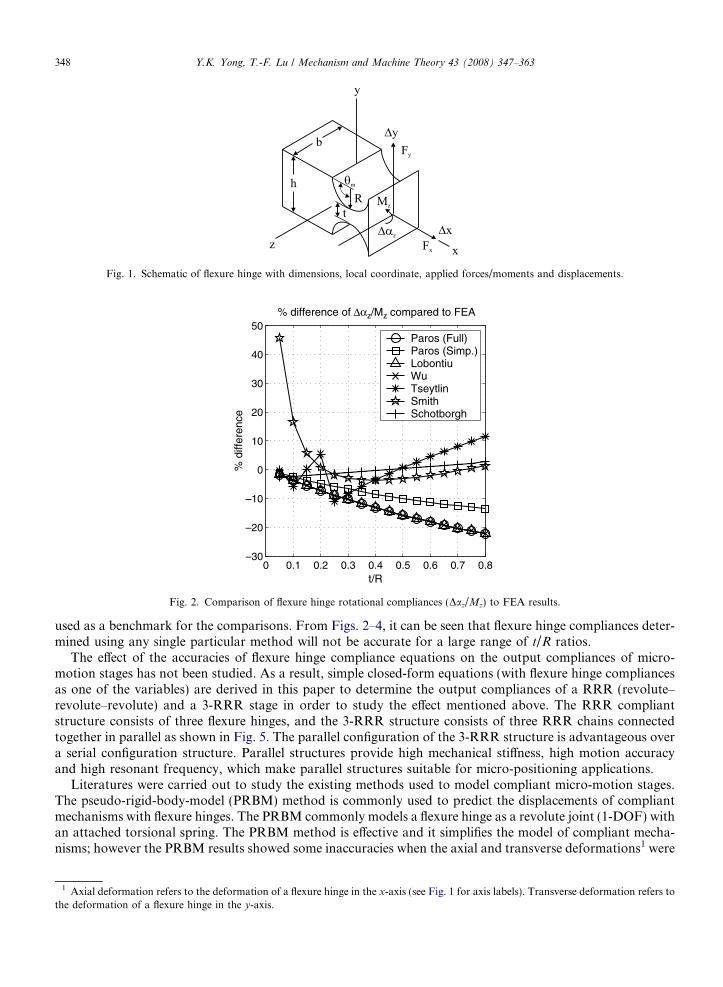
Fig. 1. Schematic of flexure hinge with dimensions, local coordinate, applied forces/moments and displacements.
0 0.1 0.2 0.3 0.4 0.5 0.6 0.7 0.8–30
–20
–10
0
10
20
30
40
50% difference of Δαz/Mz compared to FEA
t/R
% d
iffer
ence
Paros (Full)Paros (Simp.)LobontiuWuTseytlinSmithSchotborgh
Fig. 2. Comparison of flexure hinge rotational compliances (Daz/Mz) to FEA results.
348 Y.K. Yong, T.-F. Lu / Mechanism and Machine Theory 43 (2008) 347–363
used as a benchmark for the comparisons. From Figs. 2–4, it can be seen that flexure hinge compliances deter-mined using any single particular method will not be accurate for a large range of t/R ratios.
The effect of the accuracies of flexure hinge compliance equations on the output compliances of micro-motion stages has not been studied. As a result, simple closed-form equations (with flexure hinge compliancesas one of the variables) are derived in this paper to determine the output compliances of a RRR (revolute–revolute–revolute) and a 3-RRR stage in order to study the effect mentioned above. The RRR compliantstructure consists of three flexure hinges, and the 3-RRR structure consists of three RRR chains connectedtogether in parallel as shown in Fig. 5. The parallel configuration of the 3-RRR structure is advantageous overa serial configuration structure. Parallel structures provide high mechanical stiffness, high motion accuracyand high resonant frequency, which make parallel structures suitable for micro-positioning applications.
Literatures were carried out to study the existing methods used to model compliant micro-motion stages.The pseudo-rigid-body-model (PRBM) method is commonly used to predict the displacements of compliantmechanisms with flexure hinges. The PRBM commonly models a flexure hinge as a revolute joint (1-DOF) withan attached torsional spring. The PRBM method is effective and it simplifies the model of compliant mecha-nisms; however the PRBM results showed some inaccuracies when the axial and transverse deformations1 were
1 Axial deformation refers to the deformation of a flexure hinge in the x-axis (see Fig. 1 for axis labels). Transverse deformation refers tothe deformation of a flexure hinge in the y-axis.

0 0.1 0.2 0.3 0.4 0.5 0.6 0.7 0.8–100
–90
–80
–70
–60
–50
–40
–30
–20
–10
0
t/R
% d
iffer
ence
% difference of Δy/Fy compared to FEA
Paros (Full)Paros (Simp.)LobontiuWuSchotborgh
Fig. 3. Comparison of flexure hinge transverse compliances (Dy/Fy) to FEA results.
0 0.1 0.2 0.3 0.4 0.5 0.6 0.7 0.8–50
0
50
100% difference of Δx/Fx compared to FEA
t/R
% d
iffer
ence
Paros (Full)Paros (Simp.)LobontiuWuSchotborgh
Fig. 4. Comparison of flexure hinge axial compliances (Dx/Fx) to FEA results.
Y.K. Yong, T.-F. Lu / Mechanism and Machine Theory 43 (2008) 347–363 349
not incorporated into the model [2,8–11]. Pham et al. [12] derived a kinematic model of a flexure parallel mech-anism using an extended PRBM method, named the PRB-D method. The PRB-D method models flexurehinges to have all 6-DOF. They applied the PRBM and the PRB-D kinematic results to control the mechanismand the PRB-D results produced only 1/3 the error of the PRBM results. The output compliance modeling ofthe mechanism is not derived. The effect of the accuracies of flexure hinge equations on the output compliancesis not presented.
Jouaneh and Yang [13] developed a mathematical model to predict the displacement and stiffness of a ver-tical motion compliant stage. Axial and transverse deformations of hinge are considered in the analyticalmodel. Lobontiu and Garcia [14] formulated an analytical method for displacement and stiffness calculationsof planar compliant mechanisms with flexure hinges. The closed-form formulations were based on strain

a
b
Fig. 5. Compliant micro-motion stages. (a) RRR and (b) 3-RRR.
350 Y.K. Yong, T.-F. Lu / Mechanism and Machine Theory 43 (2008) 347–363
energy and Castigliano’s displacement theorem. However, the methods developed by Jouaneh & Yang andLobontiu & Garcia were only applied to 1-DOF compliant mechanisms and it is not clear if these methodswould be applicable to multi-DOF compliant mechanisms. The influence of the flexure hinge modelling accu-racies on the output compliances of the stages are not discussed.
Gao et al. [15] derived a static model for a 2-DOF compliant stage. Axial deformations of flexure hingeswere considered in these models. Paros and Weisbord’s simplified equations [7] were used to calculate boththe rotational and axial compliances of flexure hinges. Hsiao and Lin [5] derived a static model for a RRRcompliant structure with three flexure hinges. They derived the relationship between external applied loadsand deflections at the loading point. This method was not used to model a 3-RRR compliant mechanismand it was not clear if this method would be applicable to those type of mechanisms. The effect of the accu-racies of flexure hinge equations on the output compliances is not presented.
Pham and Chen [16] derived analytical models to estimate the output stiffness of a 3-DOF translationalflexure parallel mechanism (FPM). The FPM consists of three double compound linear structures, and three3-RRR compliant mechanisms. They modelled flexure hinges to have all 6-DOF. Ryu et al. [17] developed aXYh compliant stage which was driven by three piezoelectric actuators. The topology of this stage is similar toa 3-RRR mechanism except it consists of a double compound lever at each of the three input linkages. Theyformulated a mathematical model to describe the relationship between input and output displacements of thestage, by considering compliances of flexure hinges in all six axes. However, the modeling methods of Pham& Chen and Ryu et al. involve an intensive number of coordinate transformations and the methods may becomplicated. The influence of the flexure hinge modelling accuracies on the output compliances of the stagesare not presented.
Although there are various analytical models developed to calculate displacements and compliances ofmicro-motion stages, only a few research groups derived output compliance models for RRR and 3-RRRmicro-motion stages. Accuracies of these developed models are partly influenced by the accuracies of the flex-ure hinge equations used in the models; however this issue has not been investigated. Flexure hinge complianceequations were previously derived using methods such as the Castigliano’s second theorem [5,6], finite elementanalysis [2–4] and the integration of linear differential equations of beams [5,7]. As shown in Figs. 2–4, some ofthese flexure hinge compliance equations however provide better accuracies than the others depending on thet/R ratio of a hinge. There is a lack of literatures up to this date reporting the effect of the accuracies of flexurehinge equations on the output compliances of micro-motion stages.

Y.K. Yong, T.-F. Lu / Mechanism and Machine Theory 43 (2008) 347–363 351
This paper presents the effect of the accuracies of flexure hinge equations on the output compliances ofRRR and 3-RRR micro-motion stages. Simple closed-form equations are derived to determine the outputcompliances of the stages. The closed-form output compliance equations are expressed in terms of flexurehinge compliances, material properties and geometrical parameters. Since flexure hinge compliances are oneof the variables in the equations, previously derived flexure hinge compliances equations [3,6,7,18], which havedifferent modelling accuracies depending on different t/R ratios of flexure hinges (see Figs. 2–4) are used tocalculate the output compliances of the micro-motion stages. The results of the output compliances are com-pared to the FEA results to verify their accuracies.
2. The derivation of the output compliance matrix of the RRR compliant micro-motion stage
A RRR compliant stage is shown in Fig. 6 together with its dimensions, displacements, local coordinates offlexure hinges and the applied forces/moments. The compliances at point o 0 contributed by each flexure hingein the structure are firstly calculated. The overall compliances of the RRR compliant stage at point o 0 are thenobtained by summing all compliances (in the corresponding directions) contributed by each individual flexure
b
a
Fig. 6. RRR compliant mechanism with dimensions, local coordinates of flexure hinges, hinge and point labels. (a) Applied forces/moments at output point o 0. (b) Applied forces/moments at output point o.
352 Y.K. Yong, T.-F. Lu / Mechanism and Machine Theory 43 (2008) 347–363
hinges. Da, Dy and Dx are the rotational motions about the z-axis and the translational motions in the y- andx-axis, respectively. Similarly, CDa, CDy and CDx are the rotational and translational compliances along thecorresponding axes. The subscripts ‘‘o0i; F o0x’’, ‘‘o0i; F o0y ’’ and ‘‘o0i;Mo0z’’ indicate the displacements/compli-ances at point o 0 due to compliances of hinge i (i = 1,2,3) when output forces/moments, F o0x, F o0y and Mo0z
are applied. [Daz/Mz]i, [Dy/Fy]i and [Dx/Fx]i are compliances of Hinge i which can be calculated using previ-ously derived equations [1,3,4,6,7,18,19]. The effect of the accuracies of these flexure hinge equations on theoutput compliance results of the micro-motion stages are studied.
Noted that all flexure hinges are modelled to have 3-DOF (rotational compliance about the z-axis, axial andtransverse compliances in the x- and the y-axis). Flexure hinges are modelled as having 3-DOF instead of6-DOF due to the fact that both the RRR and 3-RRR compliant stages studied in this paper are planar.Out-of-plane compliances are very small for thick hinges (b is large), and therefore the out-of-plane compli-ances are neglected in order to simplify the modelling equations.
2.1. Output compliances due to Hinge 1
2.1.1. Rotational compliances about the z-direction of a RRR compliant stage
When output force, F o0x is applied,
Dao01;F o0x ¼ �Daz
Mz
� �1
F o0x � l4ð Þ ð1Þ
CDao01;F o0x ¼Dao01;F o0x
F o0x¼ � Daz
Mz
� �1
� l4 ð2Þ
When output force, F o0y is applied,
Dao01;F o0y ¼Daz
Mz
� �1
F o0yðl1 þ R1Þ ð3Þ
CDao01;F o0y ¼Daz
Mz
� �1
ðl1 þ R1Þ ð4Þ
When output moment, Mo0z is applied,
CDao01;Mo0z ¼Daz
Mz
� �1
ð5Þ
2.1.2. Translational compliances in the y-direction of a RRR compliant stage
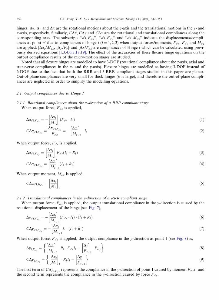
When output force, F o0x is applied, the output translational compliance in the y-direction is caused by therotational displacement of the hinge (see Fig. 7),
Dyo01;F o0x¼ � Daz
Mz
� �1
F o0x � l4ð Þ � ðl1 þ R1Þ ð6Þ
CDyo01;F o0x¼ � Daz
Mz
� �1
l4 � ðl1 þ R1Þ ð7Þ
When output force, F o0y is applied, the output compliance in the y-direction at point 1 (see Fig. 8) is,
Dy1;F o0y¼ Daz
Mz
� �1
� R1 � F o0yl1 þDyF y
� �1
� F o0y
� �ð8Þ
CDy1;F o0y¼ Daz
Mz
� �1
� R1l1 þDyF y
� �1
� �ð9Þ
The first term of CDy1;F o0yrepresents the compliance in the y-direction of point 1 caused by moment F o0yl1 and
the second term represents the compliance in the y-direction caused by force F o0y .
Fig. 8. Calculation of Dyo01;F o0 y. Dashed lines represent initial position of the RRR structure. Flexure hinge is drawn as a solid line and
rigid link is drawn as a block.
Fig. 7. Calculation of Dyo01;F o0x. Dashed lines represent initial position of the RRR structure. Flexure hinge is drawn as a solid line and
rigid link is drawn as a block.
Y.K. Yong, T.-F. Lu / Mechanism and Machine Theory 43 (2008) 347–363 353
Thus, from Eqs. (4) and (9), CDyo01;F o0ycan be calculated (see Fig. 8),
CDyo01;F o0y¼
Dao01;F o0y � l1 þ Dy1;F o0y
F o0y¼ CDao01;F o0y � l1 þ CDy1;F o0y
¼ Daz
Mz
� �1
R1l1 þ l1ðl1 þ R1Þf g þ DyF y
� �1
ð10Þ
When output moment, Mo0z is applied,
Dyo01;Mo0z¼ Daz
Mz
� �1
Mo0z � ðl1 þ R1Þ ð11Þ
CDyo01;Mo0z¼ Daz
Mz
� �1
ðl1 þ R1Þ ð12Þ
2.1.3. Translational compliances in the x-direction of a RRR compliant stage
When output force, F o0x is applied,
Dxo01;F o0x ¼DxF x
� �1
F o0x � Dao01;F o0x � l4 ð13Þ

354 Y.K. Yong, T.-F. Lu / Mechanism and Machine Theory 43 (2008) 347–363
where the first term of Dxo01;F o0x represents the x-displacement of point o 0 caused by the compliance in thex-direction of Hinge 1. The second term represents the x-displacement caused by the amplification of links(with distance of l4).
From Eq. (13),
CDxo01;F o0x ¼Dxo01;F o0x
F o0x¼ Dx
F x
� �1
� CDao01;F o0x � l4 ¼DxF x
� �1
þ Daz
Mz
� �1
l24 ð14Þ
where CDao01;F o0x is obtained from Eq. (2).When output force, F o0y is applied,
Dxo01;F o0y ¼ �Dao01;F o0y � l4 ð15Þ
CDxo01;F o0y ¼ �CDao01;F o0y � l4 ¼ �Daz
Mz
� �1
ðl1 þ R1Þl4 ð16Þ
where CDao01;F o0y is obtained from Eq. (4).When output moment, Mo0z is applied,
CDxo01;Mo0z ¼ �Daz
Mz
� �1
l4 ð17Þ
where CDao01;Mo0z is obtained from Eq. (5).Thus, the output compliance matrix of RRR mechanism at point o 0 due to compliances of Hinge 1 is,
C1 ¼CDxo01;F o0x CDxo01;F o0y CDxo01;Mo0z
CDyo01;F o0xCDyo01;F o0y
CDyo01;Mo0z
CDao01;F o0x CDao01;F o0y CDao01;Mo0z
264
375 ð18Þ
Displacements of RRR mechanism at point o 0 due to compliances of Hinge 1 when output forces/moments areapplied are,
½DX o01 DY o01 Dco01 �T ¼ C1 � F o0 ð19Þ
where F o0 ¼ ½ F o0x F o0y Mo0z �T.
2.2. Output compliances due to Hinge 2
The compliances of RRR mechanism due to Hinge 2 are calculated in the local coordinate (x2,y2) of Hinge2 (see Fig. 6). This compliance matrix will be rotated by 90� when the summation of all the three compliancematrices (C1,C2,C3) of flexure hinges are conducted to obtain the overall output compliance matrix of theRRR mechanism. Similar procedures are carried out as presented in Section 2.1 and the following compliancesare obtained.
2.2.1. Rotational compliances about the z-direction of a RRR compliant stageWhen output force, F o0x is applied,
CDao02;F o0x ¼ �Daz
Mz
� �2
ðl2 þ l3 þ R2 þ 2R3Þ ð20Þ
When output force, F o0y is applied,
CDao02;F o0y ¼ 0 ð21Þ
When output force, Mo0z is applied,
CDao02;Mo0z ¼Daz
Mz
� �2
ð22Þ

Y.K. Yong, T.-F. Lu / Mechanism and Machine Theory 43 (2008) 347–363 355
2.2.2. Translational compliances in the y-direction of a RRR compliant stage
When output force, F o0x is applied, the compliance in the y-direction (local coordinate) at point 2 is,
CDy2;F o0x¼ � Daz
Mz
� �2
� R2 l2 þ l3 þ 2R3ð Þ þ DyF y
� �2
� �ð23Þ
The procedure of calculating CDyo02;F o0xis similar to CDyo01;F o0x
. The first term of CDy2;F o0xrepresents the com-
pliance in the y-direction of point 2 caused by moment, F o0xðl2 þ l3 þ 2R3Þ and the second term represents thecompliance in the y-direction caused by force, F o0x.
Thus,
CDyo02;F o0x¼
Dao02;F o0x � ðl2 þ l3 þ 2R3Þ þ Dy2;F o0x
F o0x¼ CDao02;F o0x � ðl2 þ l3 þ 2R3Þ þ CDy2;F o0x
¼ � Daz
Mz
� �2
ðl2 þ l3 þ 2R3Þðl2 þ l3 þ 2R2 þ 2R3Þ �DyF y
� �2
ð24Þ
where CDao02;F o0x is obtained from Eq. (20) and CDy2;F o0xis obtained from Eq. (23).
When output force, F o0y is applied,
CDyo02;F o0y¼ 0 ð25Þ
When output force, Mo0z is applied,
CDyo02;Mo0z¼ Daz
Mz
� �2
ðl2 þ l3 þ R2 þ 2R3Þ ð26Þ
2.2.3. Translational compliances in the x-direction of a RRR compliant stage
When output force, F o0x is applied,
CDxo02;F o0x ¼ 0 ð27Þ
When output force, F o0y is applied,
CDxo02;F o0y ¼DxF x
� �2
ð28Þ
When output force, Mo0z is applied,
CDao02;Mo0z ¼ 0 ð29Þ
Thus, the output compliance matrix of RRR mechanism at point o 0 due to compliances of Hinge 2 is,
C2 ¼CDxo02;F o0x CDxo02;F o0y CDxo02;Mo0z
CDyo02;F o0xCDyo02;F o0y
CDyo02;Mo0z
CDao02;F o0x CDao02;F o0y CDao02;Mo0z
264
375 ð30Þ
Displacements of RRR mechanism at o 0 due to compliances of Hinge 2, when output forces/moments are ap-plied are,
½DX o02 DY o02 Dco02 �T ¼ C2 � F o0 ð31Þ
2.3. Output compliances due to Hinge 3
Similar to Section 2.2, compliances of RRR mechanism due to Hinge 3 are calculated in the local coordi-nate (x3,y3) of Hinge 3. This compliance matrix will be rotated by 90� when the summation of all the threecompliance matrices (C1,C2,C3) of flexure hinges are conducted to obtain the overall output compliancematrix of the RRR stage.

356 Y.K. Yong, T.-F. Lu / Mechanism and Machine Theory 43 (2008) 347–363
2.3.1. Rotational compliances about the z-direction of a RRR compliant stage
When output force, F o0x is applied,
CDao03;F o0x ¼ �Daz
Mz
� �3
� ðl3 þ R3Þ ð32Þ
When output force, F o0y is applied,
CDao03;F o0y ¼ 0 ð33Þ
When output force, Mo0z is applied,
CDao03;Mo0z ¼Daz
Mz
� �3
ð34Þ
2.3.2. Translational compliances in the y-direction of a RRR compliant stage
When output force, F o0x is applied, the compliance in the y-direction (local coordinate) at point 3 is,
CDy3;F o0x¼ � Daz
Mz
� �3
� R3 � l3 þDyF y
� �3
� �ð35Þ
Thus, from Eqs. (32) and (35),
CDyo03;F o0x¼ CDao03;F o0x � l3 þ CDy3;F o0x
¼ � Daz
Mz
� �3
ðl3 þ 2R3Þl3 �DyF y
� �3
ð36Þ
When output force, F o0y is applied,
CDyo03;F o0y¼ 0 ð37Þ
When output force, Mo0z is applied,
CDyo03;Mo0z¼ Daz
Mz
� �3
ðl3 þ R3Þ ð38Þ
2.3.3. Translational compliances in the x-direction of a RRR compliant stage
When output force, F o0x is applied,
CDxo03;F o0x ¼ 0 ð39Þ
When output force, F o0y is applied,
CDxo03;F o0y ¼DxF x
� �3
ð40Þ
When output moment, Mo0z is applied,
CDxo03;Mo0z ¼ 0 ð41Þ
Thus, the output compliance matrix of RRR mechanism at point o 0 due to compliances of Hinge 3 is,
C3 ¼CDxo03;F o0x CDxo03;F o0y CDxo03;Mo0z
CDyo03;F o0xCDyo03;F o0y
CDyo03;Mo0z
CDao03;F o0x CDao03;F o0y CDao03;Mo0z
264
375 ð42Þ
Displacements of RRR mechanism at point o 0 due to compliances of Hinge 3 when output forces/moments areapplied,
DX o03 DY o03 Dco03½ �T ¼ C3 � F o0 ð43Þ
Y.K. Yong, T.-F. Lu / Mechanism and Machine Theory 43 (2008) 347–363 357
2.4. Output compliances of RRR compliant mechanism
The output compliance matrix of the RRR mechanism at point o 0 is equal to the sum of all the three com-pliance matrices, C1, C2 and C3. C2 and C3 are derived in their local coordinates (x2–y2 and x3–y3) which areorientated 90� from x1–y1. Therefore, C2 and C3 matrices are rotated by 90� before the summation.
Fig. 9.solid li
CRRR;o0 ¼ C1 þ T p=2 � C2 þ T p=2 � C3 ð44Þ
where,
T p=2 ¼cosðp=2Þ � sinðp=2Þ 0
sinðp=2Þ cosðp=2Þ 0
0 0 1
264
375 ð45Þ
The output displacements at point o 0 of the RRR mechanism is,
DxRRR DyRRR DcRRR½ �To0 ¼ CRRR;o0 � F o0 ð46Þ
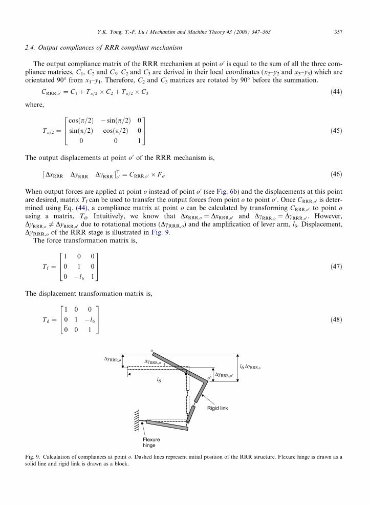
When output forces are applied at point o instead of point o 0 (see Fig. 6b) and the displacements at this pointare desired, matrix Tf can be used to transfer the output forces from point o to point o 0. Once CRRR;o0 is deter-mined using Eq. (44), a compliance matrix at point o can be calculated by transforming CRRR;o0 to point o
using a matrix, Td. Intuitively, we know that DxRRR;o ¼ DxRRR;o0 and DcRRR;o ¼ DcRRR;o0 . However,DyRRR;o 6¼ DyRRR;o0 due to rotational motions (DcRRR,o) and the amplification of lever arm, l6. Displacement,DyRRR,o of the RRR stage is illustrated in Fig. 9.
The force transformation matrix is,
T f ¼1 0 0
0 1 0
0 �l6 1
264
375 ð47Þ
The displacement transformation matrix is,
T d ¼1 0 0
0 1 �l6
0 0 1
264
375 ð48Þ
Calculation of compliances at point o. Dashed lines represent initial position of the RRR structure. Flexure hinge is drawn as ane and rigid link is drawn as a block.
358 Y.K. Yong, T.-F. Lu / Mechanism and Machine Theory 43 (2008) 347–363
Therefore, the output displacements at o of the RRR mechanism is,
DxRRR
DyRRR
DcRRR
264
375
o
¼ T d � CRRR;o0 � ðT f � F oÞ ð49Þ
Thus, the output compliances at point o is,
CRRR;o ¼ T d � CRRR;o0 � T f ð50Þ
where F o ¼ ½ F ox F oy Moz �T.
3. Output compliance matrix of 3-RRR compliant micro-motion stage
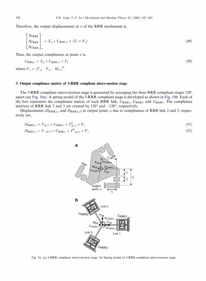
The 3-RRR compliant micro-motion stage is generated by arranging the three RRR compliant stages 120�apart (see Fig. 10a). A spring model of the 3-RRR compliant stage is developed as shown in Fig. 10b. Each ofthe box represents the compliance matrix of each RRR link, CRRR1, CRRR2 and CRRR3. The compliancematrices of RRR link 2 and 3 are rotated by 120� and �120�, respectively.
Displacements (DRRR2,o and DRRR3,o) at output point, o due to compliances of RRR link 2 and 3, respec-tively are,
DRRR2;o ¼ T 2p=3 � CRRR;o � T T2p=3 � F o ð51Þ
DRRR3;o ¼ T�2p=3 � CRRR;o � T T�2p=3 � F o ð52Þ
a
b
Fig. 10. (a) 3-RRR compliant micro-motion stage. (b) Spring model of 3-RRR compliant micro-motion stage.

Y.K. Yong, T.-F. Lu / Mechanism and Machine Theory 43 (2008) 347–363 359
where,
TableGeome
Geome
YoungPoissol1 (mml2 (mml3 (mml4 (mml6 (mmt1, t2, t
R1, R2
b (mm
T 2p=3 ¼cosð2p=3Þ � sinð2p=3Þ 0
sinð2p=3Þ cosð2p=3Þ 0
0 0 1
264
375 ð53Þ
T�2p=3 ¼cosð�2p=3Þ � sinð�2p=3Þ 0
sinð�2p=3Þ cosð�2p=3Þ 0
0 0 1
264
375 ð54Þ
T T2p=3and T T
�2p=3 are the transpose of T2p/3 and T�2p/3, respectively. CRRR,o is obtained from Eq. (50).From Eqs. (51) and (52), compliance matrices of link 2 and 3 can be expressed as,
CRRR2;o ¼ T 2p=3 � CRRR;o � T T2p=3 ð55Þ
CRRR3;o ¼ T�2p=3 � CRRR;o � T T�2p=3 ð56Þ
Since springs are arranged parallel to each other, the compliance matrix of the 3-RRR compliant micro-mo-tion stage can be found using the rule for calculating the equivalent compliances for parallel connections ofsprings,
C3RRR ¼ ðC�1RRR1 þ C�1
RRR2 þ C�1RRR3Þ
�1 ð57Þ
where CRRR1 = CRRR,o.The output displacements due to applied forces/moments can be expressed as,
½Dx Dy Dc �T3RRR ¼ C3RRR � F o ð58Þ
4. Case studies and comparison of results with FEA
Table 1 shows the geometries and material properties of a RRR and 3-RRR compliant micro-motionstages. All flexure hinges in these micro-motion stages have the same geometries and material properties.Therefore, all flexure hinges have the same compliances of [Daz/Mz]i, [Dy/Fy]i and [Dx/Fx]i (i = 1,2,3), respec-tively. The t/R ratio of all the flexure hinges is 0.63. Four cases were studied where flexure hinge equationsdeveloped by [3,7,6,18] and the FEA determined flexure hinge results obtained in this paper were used to esti-mate the compliances of flexure hinges. Since the flexure hinge compliance results of Paros & Weisbord (fullequations) [7], Lobontiu [6] and Wu & Zhou [18] are the same (see Figs. 2–4), the results of this group will berepresented by the results of Lobontiu. Table 2 shows the flexure hinge compliances calculated from the cho-sen hinge equations in each case.
For Daz/Mz, it can be seen in Fig. 2 that at t/R = 0.63, the results of Schotborgh’s equation are the closestto the FEA results, followed by Paros and Weisbord’s simplified equation and Loboutiu’s equation. For Dy/Fy
1tries and material properties of the compliant micro-motion stages
tries/material properties Value
’s modulus, E (GPa) 71.7n’s ratio, m 0.33) 15.5) 8) 10.5) 28) 27
3 (mm) 0.94, R3 (mm) 1.5) 12.7

Table 2Flexure hinge compliances calculated using various equations
Case Chosen flexure hinge equation Flexure hinge compliance
Daz/Mz (rad/Nm) Dy/Fy (m/N) Dx/Fx (m/N) Daz/Mz (rad/Nm) Dy/Fy (m/N) Dx/Fx (m/N)
Case 1 Sch [3] Sch [3] Sch [3] 0.0254 1.561 · 10�8 4.143 · 10�9
Case 2 PW (simplified) [7] PW (simplified) [7] PW (simplified) [7] 0.0222 4.994 · 10�8 1.534 · 10�9
Case 3 Lob [6] Lob [6] Lob [6] 0.0204 5.155 · 10�8 2.402 · 10�9
Case 4 Sch [3] FEA determined FEA determined 0.0254 7.190 · 10�8 2.415 · 10�9
Sch: Schotborgh et al., PW: Paros and Weisboard and Lob: Lobontiu.
360 Y.K. Yong, T.-F. Lu / Mechanism and Machine Theory 43 (2008) 347–363
and Dx/Fx, it can be seen in Figs. 3 and 4 that the results of Loboutiu’s equations are the closest to the FEAresults, followed by Paros & Weisbord’s (simplified) and Schotborgh’s equations. The results of Schotborgh’sequations for Dy/Fy and Dx/Fx have large differences when compared to the FEA and the analytical results ofParos & Weisbord (simplified) and Lobontiu. This is because Schotborgh’s equations consider differentaspects of the hinge compared to the others. Nevertheless, the discussion of Schotborgh et al.’s modellingmethod is beyond the scope of this paper.
The output compliances of the RRR and 3-RRR micro-motion stages are calculated using the flexure hingeequations aforementioned to study the effect of the accuracy of these hinge equations on the output compli-ances. The results of the analytical output compliances of the stages are shown in Tables 3–5. These analyticalcompliances are compared to the FEA results.
Table 3Comparison between analytical and FEA results for the RRR micro-motion stage
Flexure hinge compliance equation Analytical output compliance matrix (m/N, m/Nm, rad/N, rad/Nm) % difference
Case 1: Sch [3] 3.669 · 10�5 3.117 · 10�5 �1.603 · 10�3 �0.6 �0.9 �0.33.117 · 10�5 3.958 · 10�5 �1.628 · 10�3 �0.9 �1.3 �0.9�1.603 · 10�3 �1.628 · 10�3 7.634 · 10�2 �0.3 �0.9 �0.3
Case 2: PW (simplified) [7] 3.234 · 10�5 2.719 · 10�5 �1.398 · 10�3 �13.1 �13.6 �13.02.719 · 10�5 3.449 · 10�5 �1.421 · 10�3 �13.6 �14.0 �13.6�1.398 · 10�3 �1.421 · 10�3 6.659 · 10�2 �13.0 �13.6 �13.0
Case 3: Lob [6] 2.978 · 10�5 2.503 · 10�5 �1.287 · 10�3 �19.9 �20.5 �19.92.503 · 10�5 3.174 · 10�5 �1.308 · 10�3 �20.5 �20.8 �20.4�1.287 · 10�3 �1.308 · 10�3 6.130 · 10�2 �19.9 �20.4 �19.9
Sch: Schotborgh, PW: Paros and Weisboard and Lob: Lobontiu.
Table 4Comparison between analytical and FEA results for the 3-RRR micro-motion stage
Flexure hinge design equation Analytical output compliance matrix (m/N, m/Nm, rad/N, rad/Nm) % difference
Case 1: Sch [3] 5.676 · 10�7 0 0 �11.4 – –0 5.676 · 10�7 0 – �11.4 –0 0 3.593 · 10�4 – – �13.1
Case 2: PW (simplified) [7] 5.091 · 10�7 0 0 �20.5 – –0 5.091 · 10�7 0 – �20.5 –0 0 3.226 · 10�4 – – �22.0
Case 3: Lob [6] 4.720 · 10�7 0 0 �26.3 – –0 4.720 · 10�7 0 – �26.3 –0 0 2.992 · 10�4 – – �27.6
Sch: Schotborgh et al., PW: Paros and Weisboard and Lob: Lobontiu.

Table 5Case 4 – Comparison between analytical and FEA results for the two micro-motion stages
Case 4 Analytical output compliance matrix (m/N, m/Nm, rad/N, rad/Nm) % difference
RRR 3.711 · 10�5 3.117 · 10�5 �1.603 · 10�3 �0.3 �0.9 �0.33.117 · 10�5 3.966 · 10�5 �1.628 · 10�3 �0.9 �1.1 �0.9�1.603 · 10�3 �1.628 · 10�3 7.633 · 10�2 �0.3 �0.9 �0.3
3-RRR 6.193 · 10�7 0 0 �3.3 – –0 6.193 · 10�7 0 – �3.3 –0 0 3.953 · 10�4 – – �4.4
Y.K. Yong, T.-F. Lu / Mechanism and Machine Theory 43 (2008) 347–363 361
4.1. Finite element analysis (ANSYS)
A FEA model was generated using ANSYS. The stage was generated using 8-node, two-dimensional, planeelements (PLANE82) with two DOFs on each node, which are translations in the nodal x- and y-directions.Meshes, constraints and applied forces/moments of the FEA model are shown in Fig. 11. Unit forces/moments are applied at output point o and the corresponding nodal deformations at the point were read.The output compliance matrix of the RRR and 3-RRR micro-motion stages determined using FEA are shownin Eqs. (59) and (60), respectively.
CRRR½FEA� ¼3:720� 10�5 3:146� 10�5 �1:608� 10�3
3:15� 10�5 4:010� 10�5 �1:644� 10�3
�1:608� 10�3 �1:644� 10�3 7:653� 10�2
264
375 ð59Þ
C3RRR½FEA� ¼6:405� 10�7 0 0
0 6:405� 10�7 0
0 0 4:134� 10�4
264
375 ð60Þ
The off-diagonal compliances of C3RRR½FEA� in Eq. (60) are very small and insignificant compared to the diag-onal terms. Therefore, the off-diagonal compliances are assumed to be zero. This is expected as the 3-RRRcompliant stage has a RCC (remote-centre-of-compliance) configuration and deformations occur only alongthe direction of the applied force/moment [20].
Analytical output compliances calculated from Eqs. (50) and (57) using the chosen flexure hinge equations(see Table 2) were compared with FEA results. The differences between the analytical and the FEA results areshown in Tables 3–5.
Fig. 11. FEA model of 3-RRR compliant micro-motion stage.
362 Y.K. Yong, T.-F. Lu / Mechanism and Machine Theory 43 (2008) 347–363
4.1.1. Results and discussions
The results in Tables 3 and 4 show that the analytical output compliances of RRR and 3-RRR compliantstages calculated using Schotborgh et al.’s flexure hinge equations are the closest to the FEA results, followedby Paros & Weisbord’s (simplified) and Loboutiu’s equations. The accuracies of the output compliance resultsfollow the trend of the accuracies of the hinge equation, Daz/Mz, but not the accuracies of Dy/Fy and Dx/Fx.
The large differences of output compliances (when compared to FEA results) obtained using Paros andWeisbord’s simplified equations are expected because the t/R ratio of flexure hinges in this case is large, whichviolates the assumption of these analytical equations. The output compliances of the stages calculated usingLobontiu’s equations produce larger differences compared to that of Schotborgh’s equations. However, Lob-ontiu’s equations may produce accurate results if it would be used to calculate compliances of flexure hingeswith t/R ratio other than 0.63.
The Dy/Fy and Dx/Fx equations of Schotborgh et al. have large differences compared to the FEA deter-mined compliances for t/R = 0.63 as shown in Figs. 3 and 4. The large differences (approximately 80%) inthe Dy/Fy and Dx/Fx results do not cause large discrepancies in the output compliance results of the micro-motion stages. In order to study the degree of discrepancies of the output compliances due to Schotborghet al.’s Dy/Fy and Dx/Fx equations, these two flexure hinge equations in case 1 are replaced by the FEA deter-mined Dy/Fy and Dx/Fx and this new case is referred to as case 4. The calculated output compliances for case 4are shown in Table 5.
From Table 5, it can be seen that the output compliance results of case 4 for the RRR stage are similar tothat of case 1. This suggests that, for this particular geometry of the RRR stage, the accuracies of the Dy/Fy
and Dx/Fx have insignificant effects on the output compliances of the stage. The axial and transverse defor-mations of the flexure hinges are very small and insignificant to influence the results of the output compliancesof the RRR stage. Meanwhile, the output compliances of case 4 for the 3-RRR stage are closer to the FEAresults compared to that of case 1. The maximum difference of the output compliance results in case 4 is 4.4%compared to 13% in case 1. This suggests that for this particular 3-RRR stage, the accuracies of the Dy/Fy andDx/Fx have some effects on the output compliances of the stage (but not up to the extend of 80%). The axialand transverse deformations of flexure hinges are small but are significant enough to have small influences tothe results of the output compliances of the 3-RRR stage. As a conclusion, accurate output compliances of the3-RRR micro-motion stage can be obtained when the suitable flexure hinge equations are used.
Results in Tables 3–5 also show the advantage of the closed-form output compliance equations of themicro-motion stages presented in this paper. The flexure hinge equations, Daz/Mz, Dy/Fy and Dx/Fx are vari-ables in the output compliance equations. Therefore, researchers can choose the most suitable flexure hingecompliance equation by referring to Figs. 2–4 (based on the t/R ratio of the flexure hinges) in order to accu-rately calculate the output compliances of the micro-motion stages.
5. Conclusions
The effect of the accuracies of flexure hinge equations on the output compliances of micro-motion stages arestudied. Simple closed-form equations are derived in this paper to determine the output compliances of a RRRand a 3-RRR micro-motion stage. The flexure hinge equations, Daz/Mz, Dy/Fy and Dx/Fx are variables in theoutput compliance equations of the stages; therefore flexure hinge compliance equations with different accu-racies (which vary with the t/R ratios of hinges) can be used to calculate the output compliances. It was foundthat the accuracy of the output compliances mainly influenced by the accuracies of the Daz/Mz equations. Itwas also found that the accuracies of the Dy/Fy and D x/Fx equations have insignificant effects on the accu-racies of the output compliances of the RRR stage. However, the accuracies of these equations influencethe accuracies of the output compliances of the 3-RRR stage. As a conclusion, accurate output compliancesof the 3-RRR micro-motion stage can be obtained when the most suitable flexure hinge equation are used. Thesuitable flexure hinge equations can be chosen (based on the t/R ratio of the flexure hinges) by referring toFigs. 2–4.
Experiments will be conducted in the near future to further justify the accuracies of the presented outputcompliance results. Closed-form equations of calculating the input compliances of the stages are derived. The

Y.K. Yong, T.-F. Lu / Mechanism and Machine Theory 43 (2008) 347–363 363
effect of the accuracies of flexure hinge equations on the input compliances of micro-motion stages will be pre-sented in near future.
Acknowledgements
The authors greatly acknowledge the support of the Adelaide Robotics Research Group at the Universityof Adelaide and the use of its facilities. The authors also acknowledge the instrumentation and workshop staffat the School of Mechanical Engineering for all their help. Also, a special thanks to George Osborne for hisinnovative ideas and excellent craftsmanship.
References
[1] Y.M. Tseytlin, Notch flexure hinges: an effective theory, Review of Scientific Instruments 73 (9) (2002) 3363–3368.[2] I. Her, J.C. Chang, A linear scheme for the displacement analysis of micropositioning stages with flexure hinges, Journal of
Mechanical Design Transactions of the ASME 116 (1994) 770–776.[3] W.O. Schotborgh, F.G. Kokkeler, H. Tragter, F.J. van Houten, Dimensionless design graphs for flexure elements and a comparison
between three flexure elements, Precision Engineering 29 (2005) 41–47.[4] S. Smith, D. Chetwynd, D. Bowen, Design and assessment of monolithic high precision translation mechanisms, Journal of Physics E:
Scientific Instruments 20 (1987) 977–983.[5] F.-Z. Hsiao, T.-W. Lin, Analysis of a novel flexure hinge with three degrees of freedom, Review of Scientific Instruments 72 (2) (2001)
1565–1573.[6] N. Lobontiu, Compliant Mechanisms: Design of Flexure Hinges, CRC Press, 2003.[7] J.M. Paros, L. Weisbord, How to design flexure hinges, Machine Design 37 (1965) 151–156.[8] F. Scire, E. Teague, Piezodriven 50-lm range stage with subnanometer resolution, Review of Scientific Instruments 49 (12) (1978)
1735–1740.[9] E. Furukawa, M. Mizuno, T. Doi, Development of a flexure-hinged translation mechanism driven by two piezoelectric stacks, JSME
International Journal, Series C: Dynamics, Control, Robotics, Design and Manufacturing 34 (4) (1995) 743–748.[10] R. Yang, M. Jouaneh, R. Schweizer, Design and characterisation of a low-profile micropositioning stage, Precision Engineering 18
(1996) 20–29.[11] W. Zhang, J. Zou, L. Watson, W. Zhao, The constant-jacobian method for kinematics of a three-DOF planar micro-motion stage,
Journal of Robotic Systems 19 (2) (2002) 63–72.[12] H.-H. Pham, I.-M. Chen, H.-C. Yeh, Micro-motion selective-actuation XYZ flexure parallel mechanism: design and modeling,
Journal of Micromechatronics 3 (1) (2005) 51–73.[13] M. Jouaneh, R. Yang, Modeling of flexure-hinge type lever mechanisms, Precision Engineering 27 (2003) 407–418.[14] N. Lobontiu, E. Garcia, Analytical model of displacement amplification and stiffness optimization for a class of flexure-based
compliant mechanisms, Computers and Structures 81 (2003) 2797–2810.[15] P. Gao, S. Swei, Z. Yuan, A new piezodriven precision micropositioning stage utilizing flexure hinges, Nanotechnology 10 (1999) 394–
398.[16] H.-H. Pham, I.-M. Chen, Stiffness modeling of flexure parallel mechanism, Precision Engineering 29 (2005) 467–478.[17] J.W. Ryu, D. Gweon, K.S. Moon, Optimal design of a flexure hinge based xyh wafer stage, Precision Engineering 21 (1997) 18–28.[18] Y. Wu, Z. Zhou, Design calculations for flexure hinges, Review of Scientific Instruments 73 (8) (2002) 3101–3106.[19] S.T. Smith, V.G. Badami, J.S. Dale, Y. Xu, Elliptical flexure hinges, Review of Scientific Instruments 68 (3) (1997) 1474–1483.[20] W.-K. Kim, B.-J. Yi, W. Cho, RCC characteristics of planar/spherical three degree-of-freedom parallel mechanisms with joint
compliances, Journal of Mechanical Design 122 (2000) 10–16.