Embed Size (px)
Citation preview
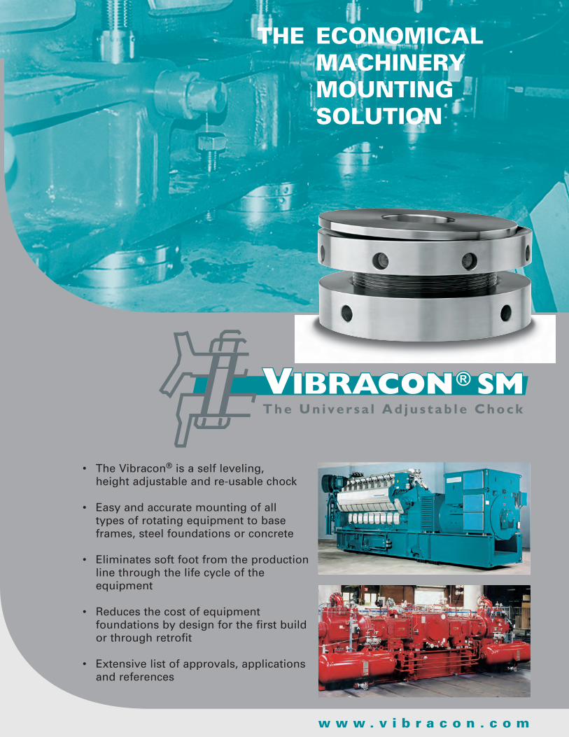
w w w . v i b r a c o n . c o m
• TheVibracon®isaselfleveling, heightadjustableandre-usablechock
• Easyandaccuratemountingofall typesofrotatingequipmenttobase
frames,steelfoundationsorconcrete
• Eliminatessoftfootfromtheproductionlinethroughthelifecycleoftheequipment
• Reducesthecostofequipmentfoundationsbydesignforthefirstbuildorthroughretrofit
• Extensivelistofapprovals,applicationsandreferences
The economical machinery mounTing soluTion
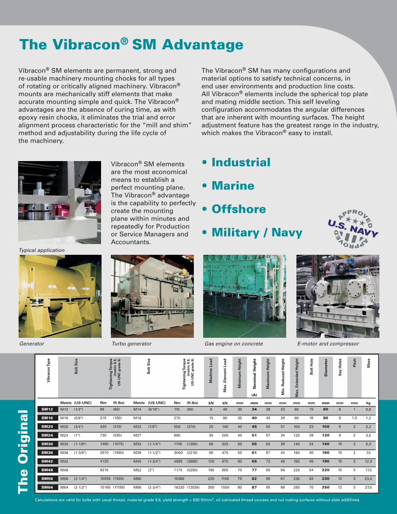
The Vibracon® SM Advantage
Vibracon® SM elements are permanent, strong and re-usable machinery mounting chocks for all types of rotating or critically aligned machinery. Vibracon® mounts are mechanically stiff elements that make accurate mounting simple and quick. The Vibracon® advantages are the absence of curing time, as with epoxy resin chocks, it eliminates the trial and error alignment process characteristic for the “mill and shim” method and adjustability during the life cycle of the machinery.
Vibracon® SM elements are the most economical means to establish a perfect mounting plane. The Vibracon® advantage is the capability to perfectly create the mounting plane within minutes and repeatedly for Production or Service Managers and Accountants.
The Vibracon® SM has many configurations and material options to satisfy technical concerns, in end user environments and production line costs. All Vibracon® elements include the spherical top plate and mating middle section. This self leveling configuration accommodates the angular differences that are inherent with mounting surfaces. The height adjustment feature has the greatest range in the industry, which makes the Vibracon® easy to install.
• Industrial
• Marine
• Offshore
• Military / Navy
Th
e O
rig
inal
Generator Turbo generator Gas engine on concrete E-motor and compressor
Calculations are valid for bolts with usual thread, material grade 8.8, yield strength > 630 N/mm2, oil lubricated thread courses and nut mating surfaces without slide additives.
Typical application
SM12
SM16
SM20
SM24
SM30
SM36
SM42
SM48
SM56
SM64
Tigh
teni
ng To
rque
(met
ric
8.8,
US
-UN
C g
rade
8)
Metric (US-UNC)
M12 (1/2")
M16 (5/8")
M20 (3/4")
M24 (1")
M30 (1-1/8")
M36 (1-3/8")
M42
M48
M56 (2-1/4")
M64 (2-1/2")
Metric (US-UNC)
M14 (9/16")
M18
M22 (7/8")
M27
M33 (1-1/4")
M39 (1-1/2")
M45 (1-3/4")
M52 (2")
M60
M68 (2-3/4")
110 (80)
270
500 (370)
890
1745 (1285)
3000 (2210)
4995 (3680)
7175 (5290)
10360
16320 (12035)
8
15
25
35
60
90
120
160
225
300
48
90
140
200
325
475
675
850
1150
1500
30
35
40
45
50
55
60
70
75
80
34
40
45
51
56
61
66
77
82
87
38
45
50
57
62
67
72
85
90
95
23
26
31
34
39
44
49
56
61
66
15
19
23
28
34
40
46
54
62
70
60
80
100
120
140
160
190
220
230
250
6
6
8
8
10
10
10
10
12
12
1
1,5
2
2
2
2
2
3
3
3
Tigh
teni
ng To
rque
(met
ric
8.8,
US
-UN
C g
rade
8)
85 (60)
215 (160)
420 (310)
730 (535)
1460 (1075)
2570 (1890)
4125
6210
10035 (7400)
15165 (11185)
Nm (ft.lbs) Nm (ft.lbs)
Mac
hine
Loa
d
Max
. Ele
men
t Lo
ad
Min
. Red
uced
Hei
ght
kN kN mm mm mm mm mmmm mmmm
Vib
raco
n Ty
pe
Bol
t S
ize
Bol
t S
ize
Min
imum
Hei
ght
No
min
al H
eig
ht
Max
imum
Hei
ght
Bol
t H
ole
Dia
met
er
Key
Hol
es
0,6
1,2
2,2
3,5
5,3
7,5
12,0
17,0
23,0
27,0
kg
Mas
s
Pitc
h
(A)
60
80
100
120
140
160
190
220
230
250
Max
. Ext
ende
d H
eigh
t
mm
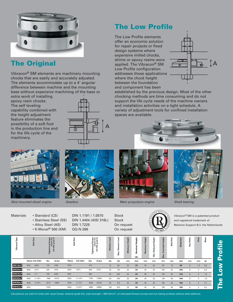
Materials • Standard (CS) DIN 1.1191 / 1.0570 Stock • Stainless Steel (SS) DIN 1.4404 (AISI 316L) Stock • Alloy Steel (AS) DIN 1.7225 On request • K-Monel® 500 (KM) QQ-N-286 On request
Th
e Lo
w P
rofi
le
Skid mounted diesel engine Gearbox Main propulsion engine Shaft bearing
Calculations are valid for bolts with usual thread, material grade 8.8, yield strength > 630 N/mm2, oil lubricated thread courses and nut mating surfaces without slide additives.
Vibracon® SM is a patented product
and registered trademark of
Machine Support B.V. the Netherlands
SM16LP
SM20LP
SM24LP
SM30LP
SM36LP
SM42LP
Vib
raco
n Ty
pe
Tigh
teni
ng To
rque
(met
ric
8.8,
US
-UN
C g
rade
8)
215 (160)
420 (310)
730 (535)
1460 (1075)
2570 (1890)
4125
Nm (ft.lbs)
M16 (5/8")
M20 (3/4")
M24 (1")
M30 (1-1/8")
M36 (1-3/8")
M42
Bol
t S
ize
Metric (US-UNC)
M18
M22 (7/8")
M27
M33 (1-1/4")
M39 (1-1/2")
M45 (1-3/4")
Bol
t S
ize
Metric (US-UNC)
Tigh
teni
ng To
rque
(met
ric
8.8,
US
-UN
C g
rade
8)
270
500 (370)
890
1745 (1285)
3000 (2210)
4995 (3680)
Nm (ft.lbs)
90
140
200
325
475
675
Max
. Ele
men
t Lo
ad
kN
Mac
hine
Loa
d
15
25
35
60
90
120
kN
Min
imum
Hei
ght
20
20
20
20
30
35
mm
Min
. Red
uced
Hei
ght
20
20
20
20
30
35
mm
30
30
30
30
40
45
Max
imum
Hei
ght
mm
19
23
29
35
40
46
Bol
t H
ole
mm
80
100
120
140
160
190
Max
. Ext
ende
d H
eigh
t
mm
0,6
0,9
1,3
1,8
3,7
6,2
Mas
s
kg
6
6
6
6
6
6
Key
Hol
es
mm
1,5
2
2
2
2
2
Pitc
h
mm
80
100
120
140
160
190
Dia
mete
r
mm
25
25
25
25
35
40
No
min
al H
eig
ht
mm
(A)
The Original Vibracon® SM elements are machinery mounting chocks that are easily and accurately adjusted. The elements accommodate up to a 4˚ angular difference between machine and the mounting base without expensive machining of the base or extra work of installing epoxy resin chocks. The self leveling capability combined with the height adjustment feature eliminates the possibility of a soft foot in the production line and for the life cycle of the machinery.
The Low Profile The Low Profile elements offer an economic solution for repair projects or fixed design systems where expensive milled chocks, shims or epoxy resins were applied. The Vibracon® SM Low Profile configuration addresses those applications where the chock height between the foundation and component has been established by the previous design. Most of the other chocking methods are time consuming and do not support the life cycle needs of the machine owners and installation activities on a tight schedule. A variety of adjustment tools for confined installation spaces are available.

Additional Vibracon® SM Applications
For mounting instructions, references and comprehensive information check:
w w w . v i b r a c o n . c o mThe Vibracon® mount has been rigorously tested in the laboratory and the field. In all types of environments and applications under the scrutiny of Designers, Production Managers, OEM Commissioning Engineers, Operators and Owners. The Vibracon® works technically and economically for many of the world’s best. Contact us for your application and trial examination, because; you need to save money.
MS FOL-VIBUS Rev. 09 d.d. 04-2010
The configurations and materials of the Vibracon® mounts are not limited to the tables illustrated in the previous sections. Many options are available and routinely deployed to solve mounting problems. Typical solutions include:
• Concrete Mounting Kit Vibracon® SM and a sole plate are matched to suit components mounted on concrete.
• Slotted Elements Industrial repair applications where the anchor bolt and the machine cannot be moved. This applies typically for shore based
engines and motors where the elements have to be installed as a traditional shim.
• Shock Hardened Elements for the Grade A Shock (MIL-STD-901) environments.
• Additional Bottom Ring For installations with larger gaps between machine foot and foundation.
• Spherical Washer Compensating angular deviations between bolt and foundation. Saves costly spot facing of mating areas.
• Stopper To avoid costly and time consuming installation of fitted bolts.
Machine Support USA Inc. Houston, TX Houma, LAToll Free: (877) 621-1777Phone: (281) 925-2849 (985) 851-5100Fax: (281) 447-0668 (985) 851-0061E-mail: [email protected]: www.machinesupport.com