Embed Size (px)
Citation preview
E
The Easiest
And Best Way
To Troubleshoot
OBD2 and OBD1
Vehicles!
Table of Contents
i CanOBD2&1
E
Title Page No.
INTRODUCTIONWhat is OBD? . . . . . . . . . . . . . . . . . . . . . . . . . . . . . . . . . . . . . . . . . . . . . . . . . . . . . 1
YOU CAN DO IT! . . . . . . . . . . . . . . . . . . . . . . . . . . . . . . . . . . . . . . . . . . . . . . . . . . . . . . . . 2SAFETY PRECAUTIONS
Safety First! . . . . . . . . . . . . . . . . . . . . . . . . . . . . . . . . . . . . . . . . . . . . . . . . . . . . . . . 3ABOUT THE CANOBD2&1 SCAN TOOL
Battery Installation / Replacement . . . . . . . . . . . . . . . . . . . . . . . . . . . . . . . . . . . . . . 5Adjustments/Settings and DTC Library . . . . . . . . . . . . . . . . . . . . . . . . . . . . . . . . . . . 5
CANOBD2&1 SCAN TOOL CONTROLSControls and Indicators . . . . . . . . . . . . . . . . . . . . . . . . . . . . . . . . . . . . . . . . . . . . . . 10Display Functions . . . . . . . . . . . . . . . . . . . . . . . . . . . . . . . . . . . . . . . . . . . . . . . . . . . 12Viewing DTC’s in the CanOBD2&1 Scan Tool’s Memory . . . . . . . . . . . . . . . . . . . . . . 14Preliminary Vehicle Diagnosis Worksheet . . . . . . . . . . . . . . . . . . . . . . . . . . . . . . . . 15
PREPARATION FOR TESTINGBefore You Begin . . . . . . . . . . . . . . . . . . . . . . . . . . . . . . . . . . . . . . . . . . . . . . . . . . . 18Vehicle Service Manuals . . . . . . . . . . . . . . . . . . . . . . . . . . . . . . . . . . . . . . . . . . . . . 19
GENERAL CODE RETRIEVAL PROCEDURESOBD1 Systems . . . . . . . . . . . . . . . . . . . . . . . . . . . . . . . . . . . . . . . . . . . . . . . . . . . . 20OBD2 Systems . . . . . . . . . . . . . . . . . . . . . . . . . . . . . . . . . . . . . . . . . . . . . . . . . . . . 20
OBD2 SystemsVehicles Covered . . . . . . . . . . . . . . . . . . . . . . . . . . . . . . . . . . . . . . . . . . . . . . . . . . 21Diagnostic Trouble Codes (DTCs) . . . . . . . . . . . . . . . . . . . . . . . . . . . . . . . . . . . . . . . 22Code Retrieval Procedure . . . . . . . . . . . . . . . . . . . . . . . . . . . . . . . . . . . . . . . . . . . . 24Erasing Diagnostic Trouble Codes (DTC’s) . . . . . . . . . . . . . . . . . . . . . . . . . . . . . . . . 30I/M Readiness Testing . . . . . . . . . . . . . . . . . . . . . . . . . . . . . . . . . . . . . . . . . . . . . . . 31
OBD2 Live Data ModeViewing Live Data . . . . . . . . . . . . . . . . . . . . . . . . . . . . . . . . . . . . . . . . . . . . . . . . . . 37Customizing Live Data (PIDs) . . . . . . . . . . . . . . . . . . . . . . . . . . . . . . . . . . . . . . . . . . 38Recording (Capturing) Live Data . . . . . . . . . . . . . . . . . . . . . . . . . . . . . . . . . . . . . . . . 39Live Data Playback . . . . . . . . . . . . . . . . . . . . . . . . . . . . . . . . . . . . . . . . . . . . . . . . . . 44Generic (Global) OBD2 PID List . . . . . . . . . . . . . . . . . . . . . . . . . . . . . . . . . . . . . . . . 46
Additional OBD2 TestsO2 Sensor Test . . . . . . . . . . . . . . . . . . . . . . . . . . . . . . . . . . . . . . . . . . . . . . . . . . . . 51Non-Continuous Test . . . . . . . . . . . . . . . . . . . . . . . . . . . . . . . . . . . . . . . . . . . . . . . . 53System Test . . . . . . . . . . . . . . . . . . . . . . . . . . . . . . . . . . . . . . . . . . . . . . . . . . . . . . . 54Vehicle ID . . . . . . . . . . . . . . . . . . . . . . . . . . . . . . . . . . . . . . . . . . . . . . . . . . . . . . . . 55
Chrysler/Jeep OBD1 SystemsChrysler/Jeep OBD1 Systems . . . . . . . . . . . . . . . . . . . . . . . . . . . . . . . . . . . . . . . . . 58Vehicles Covered . . . . . . . . . . . . . . . . . . . . . . . . . . . . . . . . . . . . . . . . . . . . . . . . . . . 59Instrument Panel Indicator Lights . . . . . . . . . . . . . . . . . . . . . . . . . . . . . . . . . . . . . . . 59Data Link Connector (DLC) . . . . . . . . . . . . . . . . . . . . . . . . . . . . . . . . . . . . . . . . . . . 59Code Retrieval Procedure . . . . . . . . . . . . . . . . . . . . . . . . . . . . . . . . . . . . . . . . . . . . 60
Ford OBD1 SystemsFord Computer System Overview . . . . . . . . . . . . . . . . . . . . . . . . . . . . . . . . . . . . . . . 64Vehicles Covered . . . . . . . . . . . . . . . . . . . . . . . . . . . . . . . . . . . . . . . . . . . . . . . . . . 64Test Connectors . . . . . . . . . . . . . . . . . . . . . . . . . . . . . . . . . . . . . . . . . . . . . . . . . . . . 68Connecting the CanOBD2&1 Scan Tool . . . . . . . . . . . . . . . . . . . . . . . . . . . . . . . . . . 68Diagnostic Trouble Codes (DTCs) . . . . . . . . . . . . . . . . . . . . . . . . . . . . . . . . . . . . . . . 69Code Retrieval Procedures . . . . . . . . . . . . . . . . . . . . . . . . . . . . . . . . . . . . . . . . . . . . 69Additional Tests for EEC-IV Systems . . . . . . . . . . . . . . . . . . . . . . . . . . . . . . . . . . . . 78
GM OBD1 SystemsYour Vehicle’s Computer System . . . . . . . . . . . . . . . . . . . . . . . . . . . . . . . . . . . . . . . 87Vehicles Covered . . . . . . . . . . . . . . . . . . . . . . . . . . . . . . . . . . . . . . . . . . . . . . . . . . 87About the CanOBD2&1 Scan Tool . . . . . . . . . . . . . . . . . . . . . . . . . . . . . . . . . . . . . . 88Data Link Connector (DLC) . . . . . . . . . . . . . . . . . . . . . . . . . . . . . . . . . . . . . . . . . . . 88Malfunction Indicator Light (MIL) . . . . . . . . . . . . . . . . . . . . . . . . . . . . . . . . . . . . . . . . 88Diagnostic Trouble Codes (DTCs) . . . . . . . . . . . . . . . . . . . . . . . . . . . . . . . . . . . . . . . 89Code Retrieval Procedure . . . . . . . . . . . . . . . . . . . . . . . . . . . . . . . . . . . . . . . . . . . . 89
Toyota/Lexus OBD1 SystemsOn-Board Vehicle Diagnostics (OBD1) . . . . . . . . . . . . . . . . . . . . . . . . . . . . . . . . . . . 93Vehicles Covered . . . . . . . . . . . . . . . . . . . . . . . . . . . . . . . . . . . . . . . . . . . . . . . . . . . 93Data Link Connector (DLC) . . . . . . . . . . . . . . . . . . . . . . . . . . . . . . . . . . . . . . . . . . . 96Instrument Panel Malfunction Indicator Lights . . . . . . . . . . . . . . . . . . . . . . . . . . . . . . 96Diagnostic Trouble Codes (DTCs) . . . . . . . . . . . . . . . . . . . . . . . . . . . . . . . . . . . . . . . 97Code Retrieval Procedure . . . . . . . . . . . . . . . . . . . . . . . . . . . . . . . . . . . . . . . . . . . . 97
Servicing DTCsServicing DTCs - OBD I . . . . . . . . . . . . . . . . . . . . . . . . . . . . . . . . . . . . . . . . . . . . . . 100Erasing DTCs (OBD I Systems) . . . . . . . . . . . . . . . . . . . . . . . . . . . . . . . . . . . . . . . . 102
GlossaryGlossary of Terms and Abbreviations . . . . . . . . . . . . . . . . . . . . . . . . . . . . . . . . . . . . 104
Warranty and ServicingLimited One Year Warranty . . . . . . . . . . . . . . . . . . . . . . . . . . . . . . . . . . . . . . . . . . . . 109Service Procedures . . . . . . . . . . . . . . . . . . . . . . . . . . . . . . . . . . . . . . . . . . . . . . . . . 109
IntroductionWHAT IS OBD?
CanOBD2&1 1
E
WHAT IS OBD?
The CanOBD2&1 Scan Tool is designed to work on mostChrysler, Ford, GM and Toyota OBD1 systems and all
OBD2 compliant vehicles.
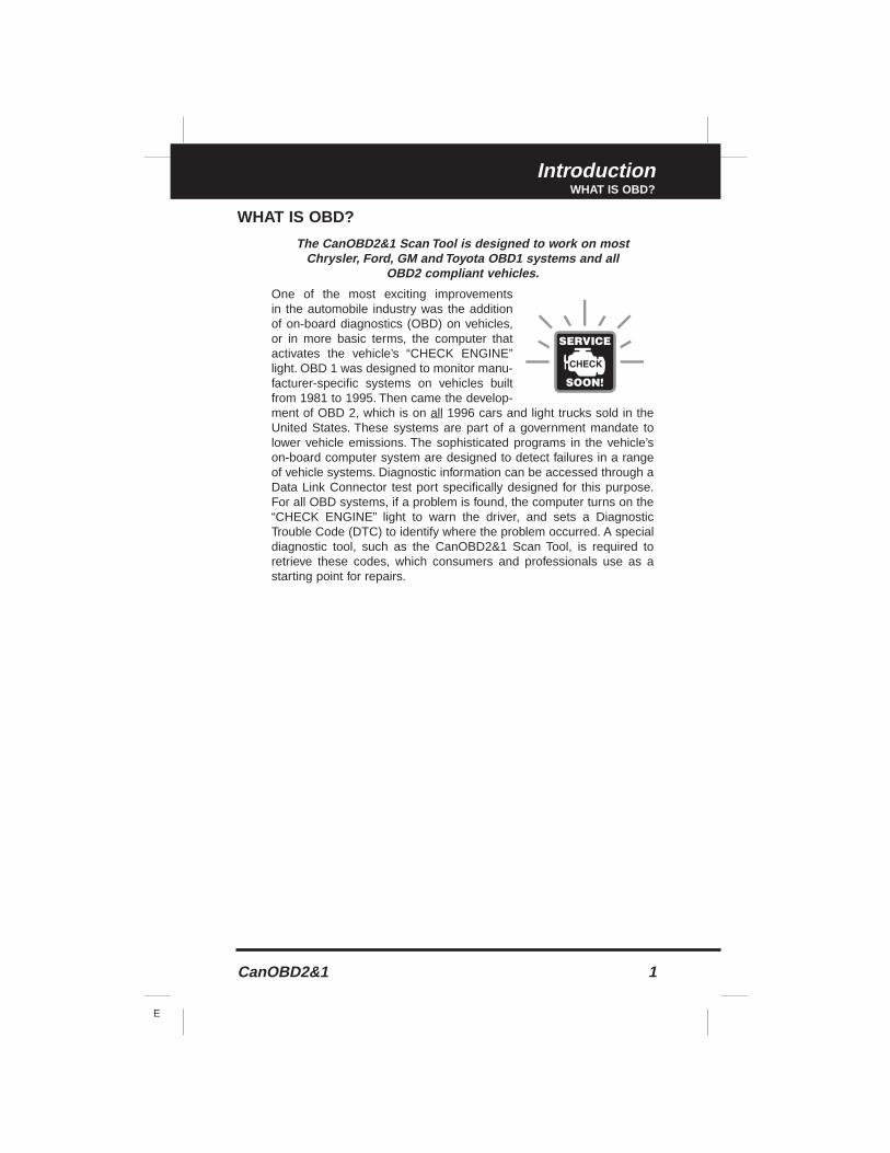
One of the most exciting improvements in the automobile industry was the additionof on-board diagnostics (OBD) on vehicles,or in more basic terms, the computer thatactivates the vehicle’s “CHECK ENGINE”light. OBD 1 was designed to monitor manu-facturer-specific systems on vehicles builtfrom 1981 to 1995. Then came the develop-ment of OBD 2, which is on all 1996 cars and light trucks sold in theUnited States. These systems are part of a government mandate tolower vehicle emissions. The sophisticated programs in the vehicle’son-board computer system are designed to detect failures in a rangeof vehicle systems. Diagnostic information can be accessed through aData Link Connector test port specifically designed for this purpose.For all OBD systems, if a problem is found, the computer turns on the“CHECK ENGINE” light to warn the driver, and sets a DiagnosticTrouble Code (DTC) to identify where the problem occurred. A specialdiagnostic tool, such as the CanOBD2&1 Scan Tool, is required toretrieve these codes, which consumers and professionals use as astarting point for repairs.
You Can Do It!EASY TO USE - EASY TO VIEW - EASY TO DEFINE
2 CanOBD2&1
E
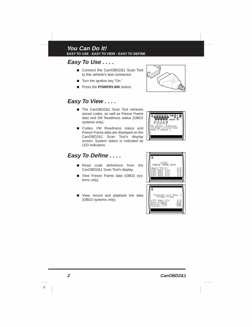
Easy To Use . . . .■ Connect the CanOBD2&1 Scan Tool
to the vehicle’s test connector.
■ Turn the ignition key "On.”
■ Press the POWER/LINK button.
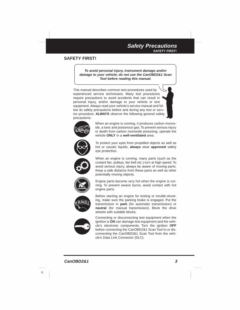
Easy To View . . . .■ The CanOBD2&1 Scan Tool retrieves
stored codes, as well as Freeze Framedata and I/M Readiness status (OBD2systems only).
■ Codes, I/M Readiness status andFreeze Frame data are displayed on theCanOBD2&1 Scan Tool’s displayscreen. System status is indicated byLED indicators.
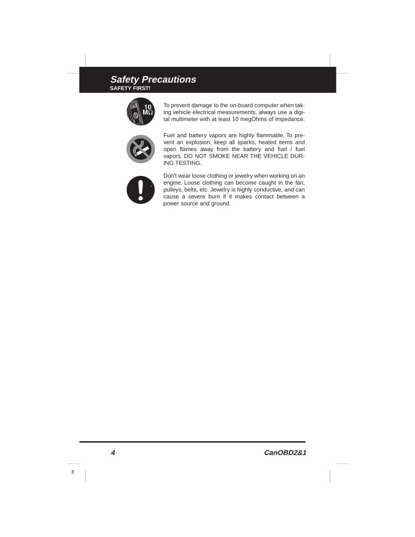
Easy To Define . . . .
■ Read code definitions from theCanOBD2&1 Scan Tool’s display.
■ View Freeze Frame data (OBD2 sys-tems only).
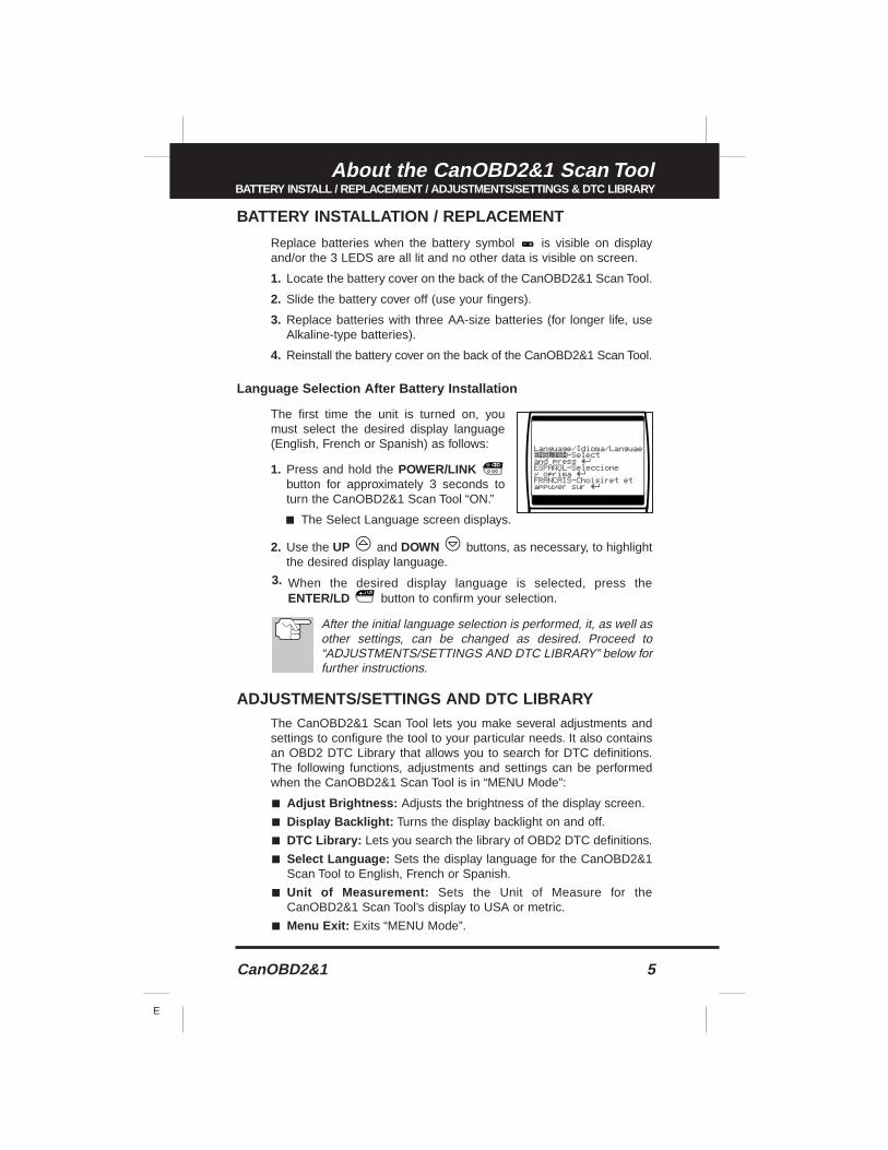
■ View, record and playback live data(OBD2 systems only).
CanOBD2&1 3
E
Safety PrecautionsSAFETY FIRST!
SAFETY FIRST!
This manual describes common test procedures used byexperienced service technicians. Many test proceduresrequire precautions to avoid accidents that can result inpersonal injury, and/or damage to your vehicle or testequipment. Always read your vehicle's service manual and fol-low its safety precautions before and during any test or serv-ice procedure. ALWAYS observe the following general safetyprecautions:
When an engine is running, it produces carbon monox-ide, a toxic and poisonous gas.To prevent serious injuryor death from carbon monoxide poisoning, operate thevehicle ONLY in a well-ventilated area.
To protect your eyes from propelled objects as well ashot or caustic liquids, always wear approved safetyeye protection.
When an engine is running, many parts (such as thecoolant fan, pulleys, fan belt etc.) turn at high speed. Toavoid serious injury, always be aware of moving parts.Keep a safe distance from these parts as well as otherpotentially moving objects.
Engine parts become very hot when the engine is run-ning. To prevent severe burns, avoid contact with hotengine parts.
Before starting an engine for testing or trouble-shoot-ing, make sure the parking brake is engaged. Put thetransmission in park (for automatic transmission) orneutral (for manual transmission). Block the drivewheels with suitable blocks.
Connecting or disconnecting test equipment when theignition is ON can damage test equipment and the vehi-cle's electronic components. Turn the ignition OFFbefore connecting the CanOBD2&1 Scan Tool to or dis-connecting the CanOBD2&1 Scan Tool from the vehi-cle’s Data Link Connector (DLC).
To avoid personal injury, instrument damage and/ordamage to your vehicle; do not use the CanOBD2&1 Scan
Tool before reading this manual.
N LDRP
4 CanOBD2&1
E
Safety PrecautionsSAFETY FIRST!
To prevent damage to the on-board computer when tak-ing vehicle electrical measurements, always use a digi-tal multimeter with at least 10 megOhms of impedance.
Fuel and battery vapors are highly flammable. To pre-vent an explosion, keep all sparks, heated items andopen flames away from the battery and fuel / fuelvapors. DO NOT SMOKE NEAR THE VEHICLE DUR-ING TESTING.
Don't wear loose clothing or jewelry when working on anengine. Loose clothing can become caught in the fan,pulleys, belts, etc. Jewelry is highly conductive, and cancause a severe burn if it makes contact between apower source and ground.
CanOBD2&1 5
E
About the CanOBD2&1 Scan ToolBATTERY INSTALL / REPLACEMENT / ADJUSTMENTS/SETTINGS & DTC LIBRARY
BATTERY INSTALLATION / REPLACEMENT
Replace batteries when the battery symbol is visible on displayand/or the 3 LEDS are all lit and no other data is visible on screen.
1. Locate the battery cover on the back of the CanOBD2&1 Scan Tool.
2. Slide the battery cover off (use your fingers).
3. Replace batteries with three AA-size batteries (for longer life, useAlkaline-type batteries).
4. Reinstall the battery cover on the back of the CanOBD2&1 Scan Tool.
Language Selection After Battery Installation
The first time the unit is turned on, youmust select the desired display language(English, French or Spanish) as follows:
1. Press and hold the POWER/LINKbutton for approximately 3 seconds toturn the CanOBD2&1 Scan Tool “ON.”
■ The Select Language screen displays.
2. Use the UP and DOWN buttons, as necessary, to highlightthe desired display language.
3. When the desired display language is selected, press theENTER/LD button to confirm your selection.
After the initial language selection is performed, it, as well asother settings, can be changed as desired. Proceed to“ADJUSTMENTS/SETTINGS AND DTC LIBRARY” below forfurther instructions.
ADJUSTMENTS/SETTINGS AND DTC LIBRARYThe CanOBD2&1 Scan Tool lets you make several adjustments andsettings to configure the tool to your particular needs. It also containsan OBD2 DTC Library that allows you to search for DTC definitions.The following functions, adjustments and settings can be performedwhen the CanOBD2&1 Scan Tool is in “MENU Mode”:
■ Adjust Brightness: Adjusts the brightness of the display screen.
■ Display Backlight: Turns the display backlight on and off.
■ DTC Library: Lets you search the library of OBD2 DTC definitions.
■ Select Language: Sets the display language for the CanOBD2&1Scan Tool to English, French or Spanish.
■ Unit of Measurement: Sets the Unit of Measure for theCanOBD2&1 Scan Tool’s display to USA or metric.
■ Menu Exit: Exits “MENU Mode”.
6 CanOBD2&1
E
About the CanOBD2&1 Scan ToolADJUSTMENTS/SETTINGS AND DTC LIBRARY
Adjustments and settings can be made only when theCanOBD2&1 Scan Tool is NOT connected to a vehicle.
To enter the MENU Mode:
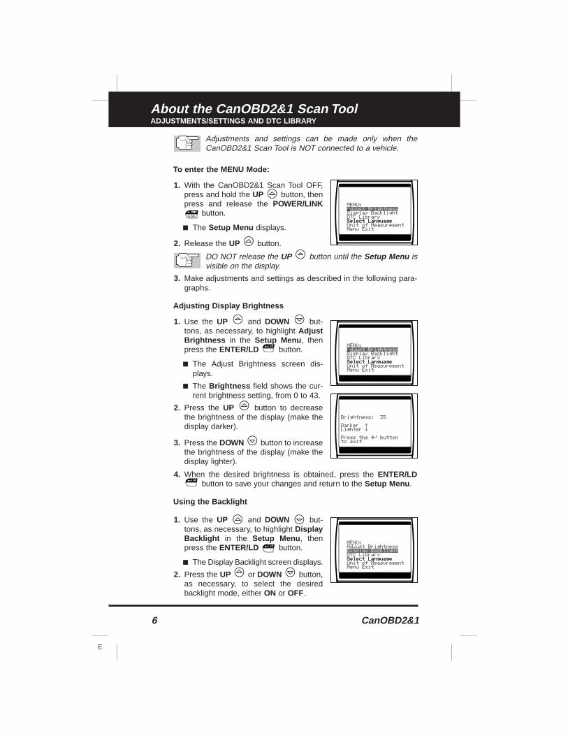
1. With the CanOBD2&1 Scan Tool OFF,press and hold the UP button, thenpress and release the POWER/LINK
button.
■ The Setup Menu displays.
2. Release the UP button.
DO NOT release the UP button until the Setup Menu isvisible on the display.
3. Make adjustments and settings as described in the following para-graphs.
Adjusting Display Brightness
1. Use the UP and DOWN but-tons, as necessary, to highlight AdjustBrightness in the Setup Menu , thenpress the ENTER/LD button.
■ The Adjust Brightness screen dis-plays.
■ The Brightness field shows the cur-rent brightness setting, from 0 to 43.
2. Press the UP button to decreasethe brightness of the display (make thedisplay darker).
3. Press the DOWN button to increasethe brightness of the display (make thedisplay lighter).
4. When the desired brightness is obtained, press the ENTER/LDbutton to save your changes and return to the Setup Menu .
Using the Backlight
1. Use the UP and DOWN but-tons, as necessary, to highlight DisplayBacklight in the Setup Menu , thenpress the ENTER/LD button.
■ The Display Backlight screen displays.
2. Press the UP or DOWN button,as necessary, to select the desiredbacklight mode, either ON or OFF.
CanOBD2&1 7
E
About the CanOBD2&1 Scan ToolADJUSTMENTS/SETTINGS AND DTC LIBRARY
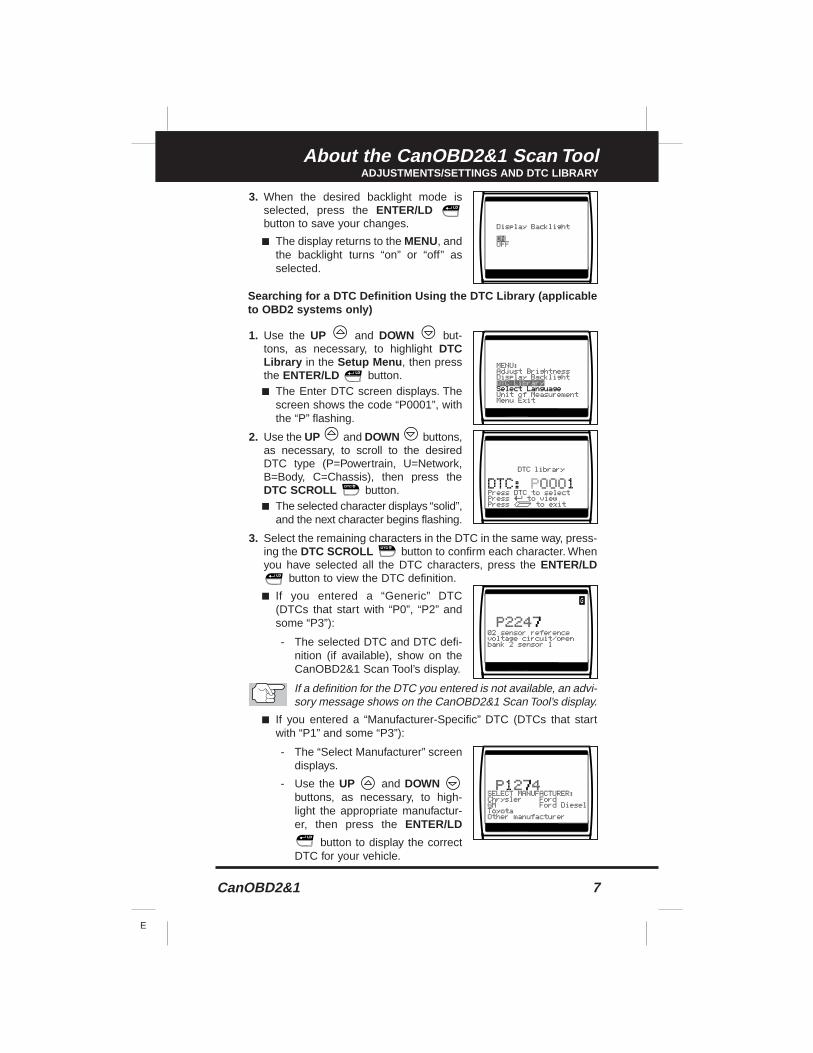
3. When the desired backlight mode isselected, press the ENTER/LDbutton to save your changes.
■ The display returns to the MENU, andthe backlight turns “on” or “off” asselected.
Searching for a DTC Definition Using the DTC Library (applicableto OBD2 systems only)
1. Use the UP and DOWN but-tons, as necessary, to highlight DTCLibrary in the Setup Menu , then pressthe ENTER/LD button.■ The Enter DTC screen displays. The
screen shows the code “P0001”, withthe “P” flashing.
2. Use the UP and DOWN buttons,as necessary, to scroll to the desiredDTC type (P=Powertrain, U=Network,B=Body, C=Chassis), then press theDTC SCROLL button.■ The selected character displays “solid”,
and the next character begins flashing.
3. Select the remaining characters in the DTC in the same way, press-ing the DTC SCROLL button to confirm each character. Whenyou have selected all the DTC characters, press the ENTER/LD
button to view the DTC definition.
■ If you entered a “Generic” DTC(DTCs that start with “P0”, “P2” andsome “P3”):
- The selected DTC and DTC defi-nition (if available), show on theCanOBD2&1 Scan Tool’s display.
If a definition for the DTC you entered is not available, an advi-sory message shows on the CanOBD2&1 Scan Tool’s display.
■ If you entered a “Manufacturer-Specific” DTC (DTCs that startwith “P1” and some “P3”):
- The “Select Manufacturer” screendisplays.
- Use the UP and DOWNbuttons, as necessary, to high-light the appropriate manufactur-er, then press the ENTER/LD
button to display the correctDTC for your vehicle.
About the CanOBD2&1 Scan ToolADJUSTMENTS/SETTINGS AND DTC LIBRARY
8 CanOBD2&1
E
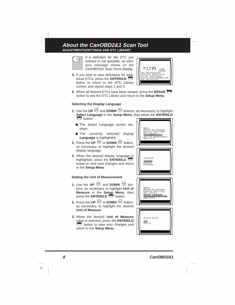
If a definition for the DTC youentered is not available, an advi-sory message shows on theCanOBD2&1 Scan Tool’s display.
4. If you wish to view definitions for addi-tional DTCs, press the ENTER/LDbutton to return to the DTC Libraryscreen, and repeat steps 2 and 3.
5. When all desired DTCs have been viewed, press the ERASEbutton to exit the DTC Library and return to the Setup Menu .
Selecting the Display Language
1. Use the UP and DOWN buttons, as necessary, to highlightSelect Language in the Setup Menu , then press the ENTER/LD
button.
■ The Select Language screen dis-plays.
■ The currently selected displayLanguage is highlighted.
2. Press the UP or DOWN button,as necessary, to highlight the desireddisplay language.
3. When the desired display language ishighlighted, press the ENTER/LDbutton to save your changes and returnto the Setup Menu .
Setting the Unit of Measurement
1. Use the UP and DOWN but-tons, as necessary, to highlight Unit ofMeasure in the Setup Menu , thenpress the ENTER/LD button.
2. Press the UP or DOWN button,as necessary, to highlight the desiredUnit of Measure .
3. When the desired Unit of Measurevalue is selected, press the ENTER/LD
button to save your changes andreturn to the Setup Menu .
About the CanOBD2&1 Scan ToolADJUSTMENTS/SETTINGS AND DTC LIBRARY
CanOBD2&1 9
E
Exiting the MENU Mode
1. Use the UP and DOWN buttons, as necessary, to highlightMenu Exit in the Setup Menu , then press the ENTER/LD but-ton.
■ If diagnostic data IS currently stored in the CanOBD2&1 ScanTool’s memory, the stored data is shown on the display.
■ If diagnostic data IS NOT currently stored in the CanOBD2&1Scan Tool’s memory, the “Linking Instructions” screen is shownon the display.
10 CanOBD2&1
E
CanOBD2&1 Scan Tool ControlsCONTROLS AND INDICATORS
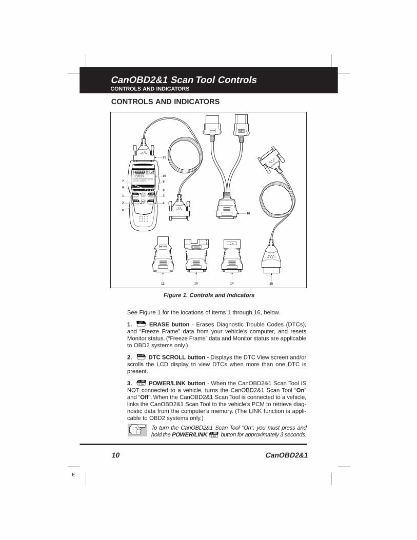
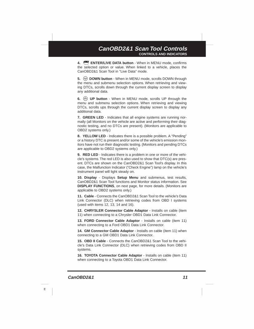
CONTROLS AND INDICATORS
See Figure 1 for the locations of items 1 through 16, below.
1. ERASE button - Erases Diagnostic Trouble Codes (DTCs),and “Freeze Frame” data from your vehicle’s computer, and resetsMonitor status. (“Freeze Frame” data and Monitor status are applicableto OBD2 systems only.)
2. DTC SCROLL button - Displays the DTC View screen and/orscrolls the LCD display to view DTCs when more than one DTC ispresent.
3. POWER/LINK button - When the CanOBD2&1 Scan Tool ISNOT connected to a vehicle, turns the CanOBD2&1 Scan Tool “On”and “Off ”. When the CanOBD2&1 Scan Tool is connected to a vehicle,links the CanOBD2&1 Scan Tool to the vehicle’s PCM to retrieve diag-nostic data from the computer’s memory. (The LINK function is appli-cable to OBD2 systems only.)
To turn the CanOBD2&1 Scan Tool "On", you must press andhold the POWER/LINK button for approximately 3 seconds.
1
2
5
3
9
4
16
11
12 13 14 15
6
7 8
10
Figure 1. Controls and Indicators
CanOBD2&1 11
E
CanOBD2&1 Scan Tool ControlsCONTROLS AND INDICATORS
4. ENTER/LIVE DATA button - When in MENU mode, confirmsthe selected option or value. When linked to a vehicle, places theCanOBD2&1 Scan Tool in "Live Data" mode.
5. DOWN button - When in MENU mode, scrolls DOWN throughthe menu and submenu selection options. When retrieving and view-ing DTCs, scrolls down through the current display screen to displayany additional data.
6. UP button - When in MENU mode, scrolls UP through themenu and submenu selection options. When retrieving and viewingDTCs, scrolls ups through the current display screen to display anyadditional data.
7. GREEN LED - Indicates that all engine systems are running nor-mally (all Monitors on the vehicle are active and performing their diag-nostic testing, and no DTCs are present). (Monitors are applicable toOBD2 systems only.)
8. YELLOW LED - Indicates there is a possible problem. A “Pending”or a history DTC is present and/or some of the vehicle’s emission mon-itors have not run their diagnostic testing. (Monitors and pending DTCsare applicable to OBD2 systems only.)
9. RED LED - Indicates there is a problem in one or more of the vehi-cle’s systems. The red LED is also used to show that DTC(s) are pres-ent. DTCs are shown on the CanOBD2&1 Scan Tool’s display. In thiscase, the Malfunction Indicator (“Check Engine”) lamp on the vehicle’sinstrument panel will light steady on.
10. Display - Displays Setup Menu and submenus, test results,CanOBD2&1 Scan Tool functions and Monitor status information. SeeDISPLAY FUNCTIONS , on next page, for more details. (Monitors areapplicable to OBD2 systems only.)
11. Cable - Connects the CanOBD2&1 Scan Tool to the vehicle’s DataLink Connector (DLC) when retrieving codes from OBD I systems(used with items 12, 13, 14 and 16).
12. CHRYSLER Connector Cable Adaptor - Installs on cable (item11) when connecting to a Chrysler OBD1 Data Link Connector.
13. FORD Connector Cable Adaptor - Installs on cable (item 11)when connecting to a Ford OBD1 Data Link Connector.
14. GM Connector Cable Adaptor - Installs on cable (item 11) whenconnecting to a GM OBD1 Data Link Connector.
15. OBD II Cable - Connects the CanOBD2&1 Scan Tool to the vehi-cle's Data Link Connector (DLC) when retrieving codes from OBD IIsystems.
16. TOYOTA Connector Cable Adaptor - Installs on cable (item 11)when connecting to a Toyota OBD1 Data Link Connector.
12 CanOBD2&1
E
CanOBD2&1 Scan Tool ControlsDISPLAY FUNCTIONS
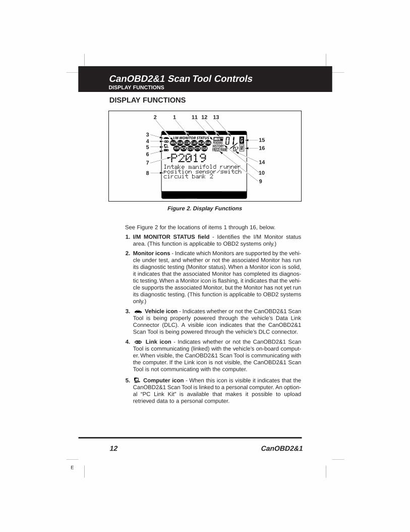
DISPLAY FUNCTIONS
See Figure 2 for the locations of items 1 through 16, below.
1. I/M MONITOR STATUS field - Identifies the I/M Monitor statusarea. (This function is applicable to OBD2 systems only.)
2. Monitor icons - Indicate which Monitors are supported by the vehi-cle under test, and whether or not the associated Monitor has runits diagnostic testing (Monitor status). When a Monitor icon is solid,it indicates that the associated Monitor has completed its diagnos-tic testing. When a Monitor icon is flashing, it indicates that the vehi-cle supports the associated Monitor, but the Monitor has not yet runits diagnostic testing. (This function is applicable to OBD2 systemsonly.)
3. Vehicle icon - Indicates whether or not the CanOBD2&1 ScanTool is being properly powered through the vehicle’s Data LinkConnector (DLC). A visible icon indicates that the CanOBD2&1Scan Tool is being powered through the vehicle’s DLC connector.
4. Link icon - Indicates whether or not the CanOBD2&1 ScanTool is communicating (linked) with the vehicle’s on-board comput-er. When visible, the CanOBD2&1 Scan Tool is communicating withthe computer. If the Link icon is not visible, the CanOBD2&1 ScanTool is not communicating with the computer.
5. Computer icon - When this icon is visible it indicates that theCanOBD2&1 Scan Tool is linked to a personal computer. An option-al “PC Link Kit” is available that makes it possible to uploadretrieved data to a personal computer.
43
2 1 11 12 13
5
8
9
10
14
1615
6
7
Figure 2. Display Functions
CanOBD2&1 13
E
CanOBD2&1 Scan Tool ControlsDISPLAY FUNCTIONS
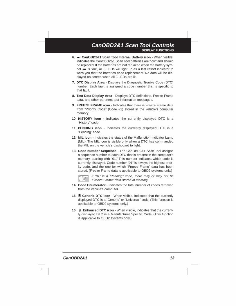
6. CanOBD2&1 Scan Tool Internal Battery icon - When visible,indicates the CanOBD2&1 Scan Tool batteries are “low” and shouldbe replaced. If the batteries are not replaced when the battery sym-bol is "on", all 3 LEDs will light up as a last resort indicator towarn you that the batteries need replacement. No data will be dis-played on screen when all 3 LEDs are lit.
7. DTC Display Area - Displays the Diagnostic Trouble Code (DTC)number. Each fault is assigned a code number that is specific tothat fault.
8. Test Data Display Area - Displays DTC definitions, Freeze Framedata, and other pertinent test information messages.
9. FREEZE FRAME icon - Indicates that there is Freeze Frame datafrom “Priority Code” (Code #1) stored in the vehicle’s computermemory.
10. HISTORY icon - Indicates the currently displayed DTC is a“History” code.
11. PENDING icon - Indicates the currently displayed DTC is a“Pending” code.
12. MIL icon - Indicates the status of the Malfunction Indicator Lamp(MIL). The MIL icon is visible only when a DTC has commandedthe MIL on the vehicle’s dashboard to light.
13. Code Number Sequence - The CanOBD2&1 Scan Tool assignsa sequence number to each DTC that is present in the computer’smemory, starting with “01.” This number indicates which code iscurrently displayed. Code number “01” is always the highest prior-ity code, and the one for which “Freeze Frame” data has beenstored. (Freeze Frame data is applicable to OBD2 systems only.)
If “01” is a “Pending” code, there may or may not be“Freeze Frame” data stored in memory.
14. Code Enumerator - Indicates the total number of codes retrievedfrom the vehicle’s computer.
15. Generic DTC icon - When visible, indicates that the currentlydisplayed DTC is a “Generic” or “Universal” code. (This function isapplicable to OBD2 systems only.)
16. Enhanced DTC icon - When visible, indicates that the current-ly displayed DTC is a Manufacturer Specific Code. (This functionis applicable to OBD2 systems only.)
14 CanOBD2&1
E
CanOBD2&1 Scan Tool ControlsVIEWING DTCs IN THE CANOBD2&1 SCAN TOOL’S MEMORY
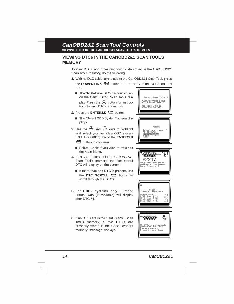
VIEWING DTCs IN THE CANOBD2&1 SCAN TOOL’SMEMORY
To view DTC’s and other diagnostic data stored in the CanOBD2&1Scan Tool’s memory, do the following:
1. With no DLC cable connected to the CanOBD2&1 Scan Tool, press
the POWER/LINK button to turn the CanOBD2&1 Scan Tool“on”.
■ The “To Retrieve DTCs” screen showson the CanOBD2&1 Scan Tool’s dis-
play. Press the button for instruc-tions to view DTC’s in memory.
2. Press the ENTER/LD button.
■ The “Select OBD System” screen dis-plays.
3. Use the and keys to highlightand select your vehicle’s OBD system(OBD1 or OBD2). Press the ENTER/LD
button to continue.
■ Select “Back” if you wish to return tothe Main Menu.
4. If DTCs are present in the CanOBD2&1Scan Tool’s memory, the first storedDTC will display on the screen.
■ If more than one DTC is present, usethe DTC SCROLL button toscroll through the DTC’s.
5. For OBD2 systems only - FreezeFrame Data (if available) will displayafter DTC #1.
6. If no DTCs are in the CanOBD2&1 ScanTool’s memory, a “No DTC’s arepresently stored in the Code Readersmemory” message displays.
CanOBD2&1 15
E
Preparation for TestingPRELIMINARY VEHICLE DIAGNOSIS WORKSHEET
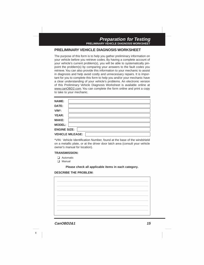
PRELIMINARY VEHICLE DIAGNOSIS WORKSHEET
The purpose of this form is to help you gather preliminary information onyour vehicle before you retrieve codes. By having a complete account ofyour vehicle's current problem(s), you will be able to systematically pin-point the problem(s) by comparing your answers to the fault codes youretrieve.You can also provide this information to your mechanic to assistin diagnosis and help avoid costly and unnecessary repairs. It is impor-tant for you to complete this form to help you and/or your mechanic havea clear understanding of your vehicle's problems. An electronic versionof this Preliminary Vehicle Diagnosis Worksheet is available online atwww.canOBD2.com. You can complete the form online and print a copyto take to your mechanic.
NAME:
DATE:
VIN*:
YEAR:
MAKE:
MODEL:
ENGINE SIZE:
VEHICLE MILEAGE:
*VIN: Vehicle Identification Number, found at the base of the windshieldon a metallic plate, or at the driver door latch area (consult your vehicleowner's manual for location).
TRANSMISSION:
❑ Automatic❑ Manual
Please check all applicable items in each category.
DESCRIBE THE PROBLEM:
16 CanOBD2&1
E
Preparation for TestingPRELIMINARY VEHICLE DIAGNOSIS WORKSHEET
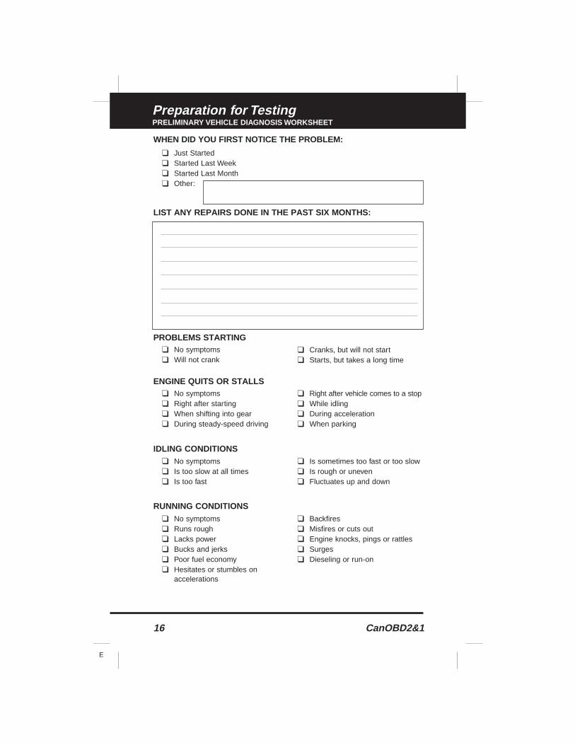
WHEN DID YOU FIRST NOTICE THE PROBLEM:
❑ Just Started❑ Started Last Week❑ Started Last Month❑ Other:
LIST ANY REPAIRS DONE IN THE PAST SIX MONTHS:
PROBLEMS STARTING
ENGINE QUITS OR STALLS
IDLING CONDITIONS
RUNNING CONDITIONS
❑ No symptoms❑ Will not crank
❑ Cranks, but will not start❑ Starts, but takes a long time
❑ No symptoms❑ Right after starting❑ When shifting into gear❑ During steady-speed driving
❑ Right after vehicle comes to a stop❑ While idling❑ During acceleration❑ When parking
❑ No symptoms❑ Is too slow at all times❑ Is too fast
❑ Is sometimes too fast or too slow❑ Is rough or uneven❑ Fluctuates up and down
❑ No symptoms❑ Runs rough❑ Lacks power❑ Bucks and jerks❑ Poor fuel economy❑ Hesitates or stumbles on
accelerations
❑ Backfires❑ Misfires or cuts out❑ Engine knocks, pings or rattles❑ Surges❑ Dieseling or run-on
CanOBD2&1 17
E
Preparation for TestingPRELIMINARY VEHICLE DIAGNOSIS WORKSHEET
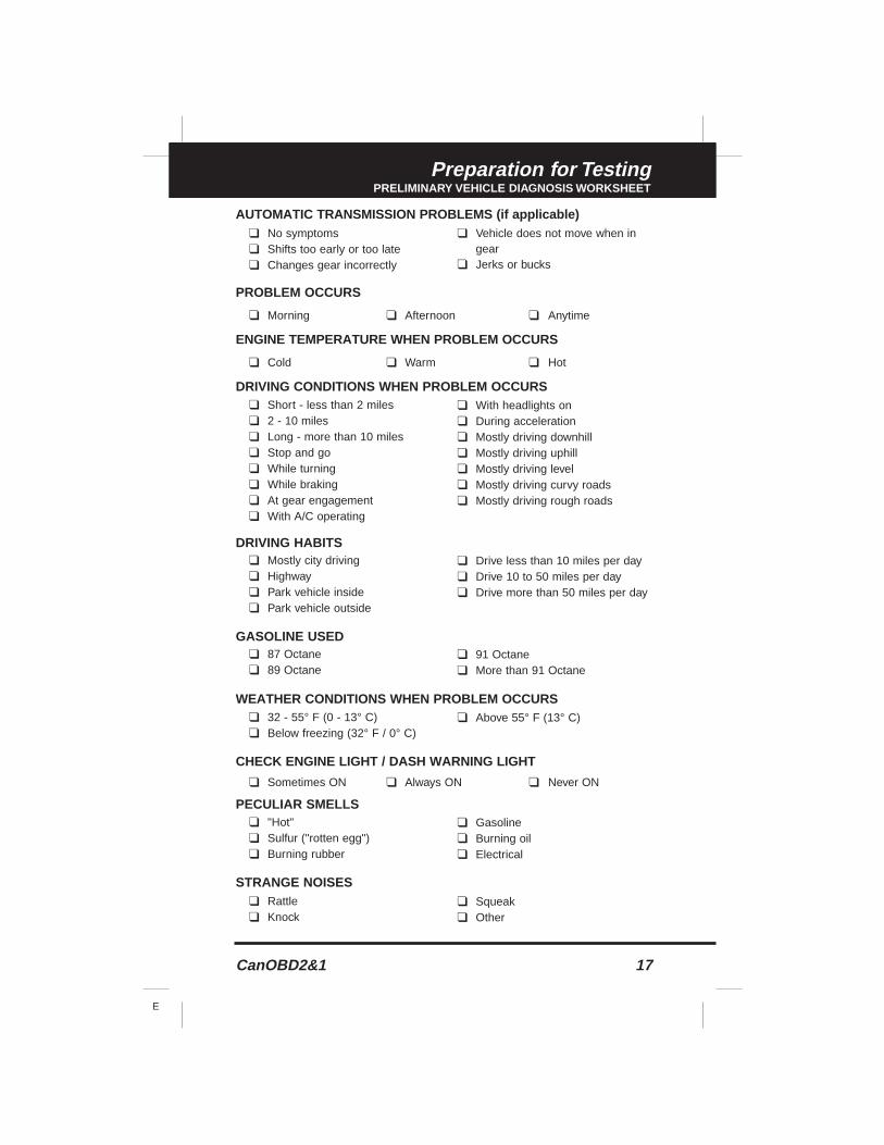
AUTOMATIC TRANSMISSION PROBLEMS (if applicable)
PROBLEM OCCURS
❑ Morning ❑ Afternoon ❑ Anytime
ENGINE TEMPERATURE WHEN PROBLEM OCCURS
❑ Cold ❑ Warm ❑ Hot
DRIVING CONDITIONS WHEN PROBLEM OCCURS
DRIVING HABITS
GASOLINE USED
WEATHER CONDITIONS WHEN PROBLEM OCCURS
CHECK ENGINE LIGHT / DASH WARNING LIGHT
❑ Sometimes ON ❑ Always ON ❑ Never ON
PECULIAR SMELLS
STRANGE NOISES
❑ Short - less than 2 miles❑ 2 - 10 miles❑ Long - more than 10 miles❑ Stop and go❑ While turning❑ While braking❑ At gear engagement❑ With A/C operating
❑ With headlights on❑ During acceleration❑ Mostly driving downhill❑ Mostly driving uphill❑ Mostly driving level❑ Mostly driving curvy roads❑ Mostly driving rough roads
❑ Mostly city driving❑ Highway❑ Park vehicle inside❑ Park vehicle outside
❑ Drive less than 10 miles per day❑ Drive 10 to 50 miles per day❑ Drive more than 50 miles per day
❑ 87 Octane❑ 89 Octane
❑ 91 Octane❑ More than 91 Octane
❑ 32 - 55° F (0 - 13° C)❑ Below freezing (32° F / 0° C)
❑ Above 55° F (13° C)
❑ "Hot"❑ Sulfur ("rotten egg")❑ Burning rubber
❑ Gasoline❑ Burning oil❑ Electrical
❑ Rattle❑ Knock
❑ Squeak❑ Other
❑ No symptoms❑ Shifts too early or too late❑ Changes gear incorrectly
❑ Vehicle does not move when in gear
❑ Jerks or bucks
18 CanOBD2&1
E
Preparation for TestingBEFORE YOU BEGIN
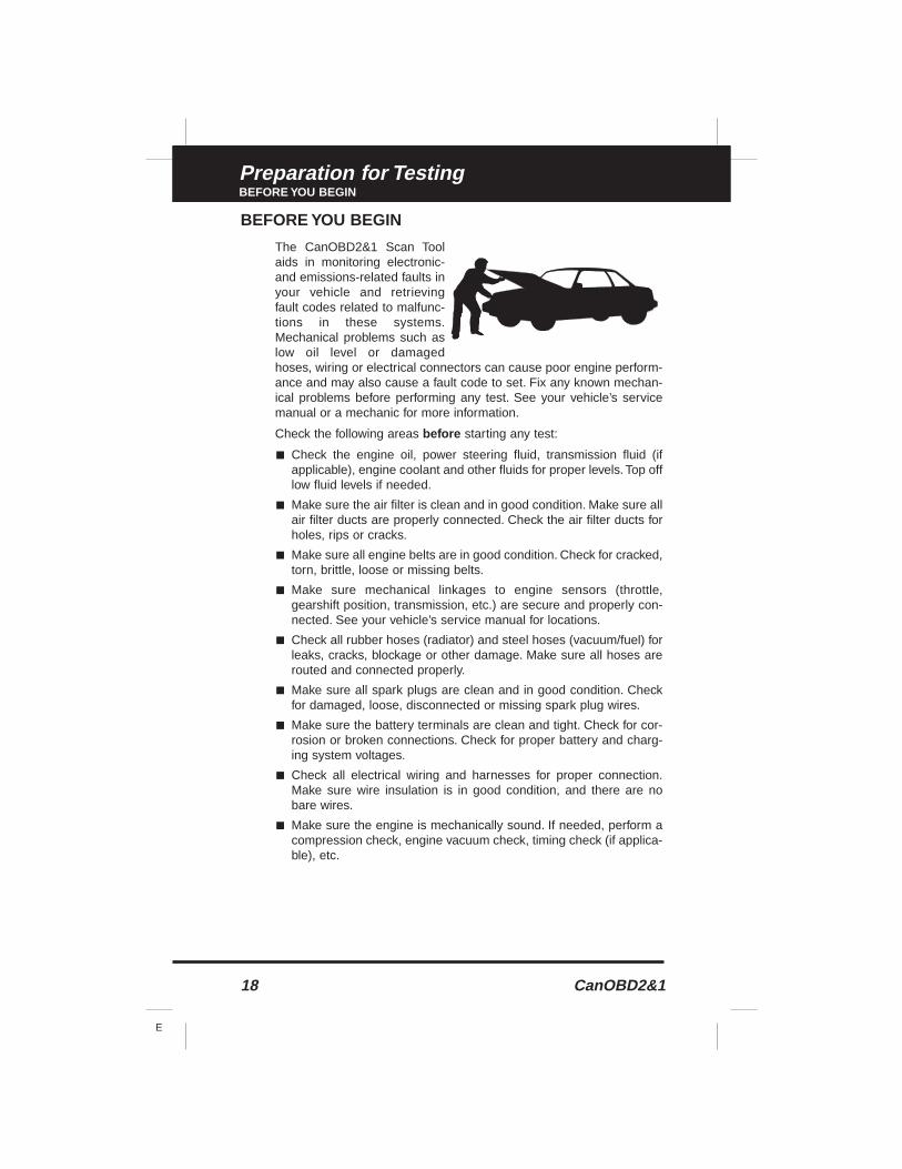
BEFORE YOU BEGIN
The CanOBD2&1 Scan Toolaids in monitoring electronic-and emissions-related faults inyour vehicle and retrievingfault codes related to malfunc-tions in these systems.Mechanical problems such aslow oil level or damagedhoses, wiring or electrical connectors can cause poor engine perform-ance and may also cause a fault code to set. Fix any known mechan-ical problems before performing any test. See your vehicle’s servicemanual or a mechanic for more information.
Check the following areas before starting any test:
■ Check the engine oil, power steering fluid, transmission fluid (ifapplicable), engine coolant and other fluids for proper levels. Top offlow fluid levels if needed.
■ Make sure the air filter is clean and in good condition. Make sure allair filter ducts are properly connected. Check the air filter ducts forholes, rips or cracks.
■ Make sure all engine belts are in good condition. Check for cracked,torn, brittle, loose or missing belts.
■ Make sure mechanical linkages to engine sensors (throttle,gearshift position, transmission, etc.) are secure and properly con-nected. See your vehicle’s service manual for locations.
■ Check all rubber hoses (radiator) and steel hoses (vacuum/fuel) forleaks, cracks, blockage or other damage. Make sure all hoses arerouted and connected properly.
■ Make sure all spark plugs are clean and in good condition. Checkfor damaged, loose, disconnected or missing spark plug wires.
■ Make sure the battery terminals are clean and tight. Check for cor-rosion or broken connections. Check for proper battery and charg-ing system voltages.
■ Check all electrical wiring and harnesses for proper connection.Make sure wire insulation is in good condition, and there are nobare wires.
■ Make sure the engine is mechanically sound. If needed, perform acompression check, engine vacuum check, timing check (if applica-ble), etc.
CanOBD2&1 19
E
Preparation for TestingVEHICLE SERVICE MANUALS
VEHICLE SERVICE MANUALS
Always refer to the manufacturer’s service manual for your vehiclebefore performing any test or repair procedures. Contact your local cardealership, auto parts store or bookstore for availability of these man-uals. The following companies publish valuable repair manuals:
■ Haynes Publications861 Lawrence DriveNewbury Park, California 91320Phone: 800-442-9637
■ Mitchell International14145 Danielson StreetPoway, California 92064Phone: 888-724-6742
■ Motor Publications5600 Crooks Road, Suite 200Troy, Michigan 48098Phone: 800-426-6867
FACTORY SOURCES
Ford, GM, Chrysler, Honda, Isuzu, Hyundai and Subaru ServiceManuals
■ Helm Inc.14310 Hamilton AvenueHighland Park, Michigan 48203Phone: 800-782-4356
20 CanOBD2&1
E
General Code Retrieval ProceduresOBD1 SYSTEMS / OBD2 SYSTEMS
Procedures for Retrieving Diagnostic Trouble Codes from OBD1 sys-tems are vehicle manufacturer specific. Each manufacturer uses theirown procedure.
Procedures for retrieving Diagnostic Trouble Codes from OBD2 systems are generic, and apply to all vehicles equipped with OBD2systems.
From the following list, select the procedure that applies to your vehi-cle’s OBD system, and proceed to appropriate section for detailedcode retrieval procedures.
OBD1 SYSTEMS
Most cars and light trucks (under 8500 GW) sold in the U.S. from early1980’s to 1995 are equipped with what is known as the first generationof On-Board Diagnostics or “OBD1”.
■ If your Chrysler/Jeep, Ford, GM or Toyota vehicle, (1995 and older)is equipped with an ‘OBD1 System”, proceed to the proper sectionas indicated below, for a detailed application list and code retrievalprocedures:
■ CHRYSLER/JEEP . . . . . . . . . . . . . . . .page 58
■ FORD . . . . . . . . . . . . . . . . . . . . . . . . .page 64
■ GM . . . . . . . . . . . . . . . . . . . . . . . . . . .page 87
■ TOYOTA . . . . . . . . . . . . . . . . . . . . . . . .page 93
OBD2 SYSTEMS
ALL 1996 and newer cars and light trucks (under 8500 GW) sold in theU.S. are equipped with what is known as the second generation of On-Board Diagnostics or “OBD2”.
■ If your vehicle (1996 and newer) is equipped with an “OBD2System”, proceed to the “OBD2 SYSTEMS” section on page 21 fora detailed application list, code retrieval procedures, Monitor status,and Freeze Frame data information.
CanOBD2&1 21
E
OBD2 SystemsVEHICLES COVERED
VEHICLES COVERED
The CanOBD2&1 Scan Tool is designed to work on all OBD 2 compli-ant vehicles. All 1996 and newer vehicles (cars and light trucks) sold inthe United States are OBD 2 compliant.
Federal law requires that all 1996 and newer cars and lighttrucks sold in the United States must be OBD 2 compliant;this includes all Domestic, Asian and European vehicles.
Some 1994 and 1995 vehicles are OBD 2 compliant. To find out if a1994 or 1995 vehicle is OBD 2 compliant, check the following:
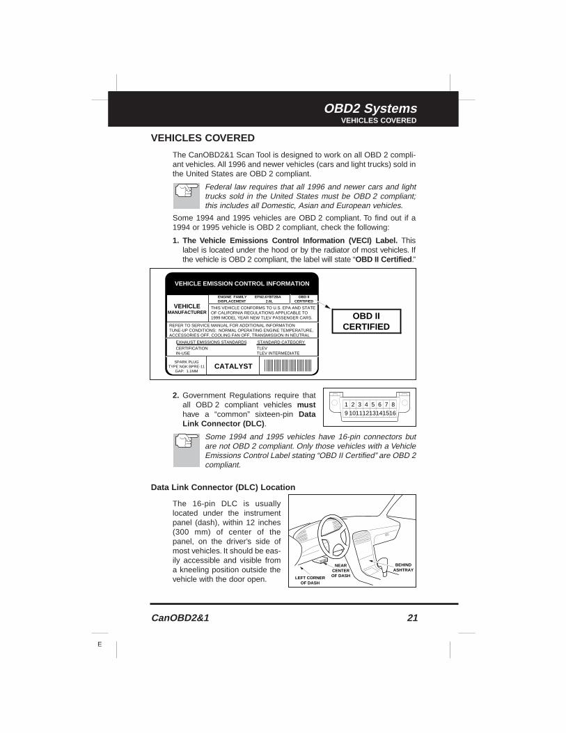
1. The Vehicle Emissions Control Information (VECI) Label. Thislabel is located under the hood or by the radiator of most vehicles. Ifthe vehicle is OBD 2 compliant, the label will state “OBD II Certified .”
2. Government Regulations require thatall OBD 2 compliant vehicles musthave a “common” sixteen-pin DataLink Connector (DLC) .
Some 1994 and 1995 vehicles have 16-pin connectors butare not OBD 2 compliant. Only those vehicles with a VehicleEmissions Control Label stating “OBD II Certified” are OBD 2compliant.
Data Link Connector (DLC) Location
The 16-pin DLC is usuallylocated under the instrumentpanel (dash), within 12 inches(300 mm) of center of thepanel, on the driver’s side ofmost vehicles. It should be eas-ily accessible and visible froma kneeling position outside thevehicle with the door open.
VEHICLE EMISSION CONTROL INFORMATION
VEHICLEMANUFACTURER
OBD IICERTIFIED
ENGINE FAMILY EFN2.6YBT2BADISPLACEMENT 2.6L
THIS VEHICLE CONFORMS TO U.S. EPA AND STATEOF CALIFORNIA REGULATIONS APPLICABLE TO1999 MODEL YEAR NEW TLEV PASSENGER CARS.
REFER TO SERVICE MANUAL FOR ADDITIONAL INFORMATIONTUNE-UP CONDITIONS: NORMAL OPERATING ENGINE TEMPERATURE,ACCESSORIES OFF, COOLING FAN OFF, TRANSMISSION IN NEUTRAL
SPARK PLUGTYPE NGK BPRE-11
GAP: 1.1MMCATALYST
EXHAUST EMISSIONS STANDARDS STANDARD CATEGORY
CERTIFICATIONIN-USE
TLEVTLEV INTERMEDIATE
OBD IICERTIFIED
1 2 3 4 5 6 7 8
9 10111213141516
NEARCENTEROF DASH
BEHINDASHTRAY
LEFT CORNEROF DASH
22 CanOBD2&1
E
OBD2 SystemsDIAGNOSTIC TROUBLE CODES (DTCs)
On some Asian and European vehicles the DLC is locatedbehind the “ashtray” (the ashtray must be removed to accessit) or on the far left corner of the dash. If the DLC cannot belocated, consult the vehicle’s service manual for the location.
DIAGNOSTIC TROUBLE CODES (DTCs)
Diagnostic Trouble Codes (DTCs) aremeant to guide you to the proper serv-ice procedure in the vehicle’s servicemanual. DO NOT replace parts basedonly on DTCs without first consultingthe vehicle’s service manual for prop-er testing procedures for that particularsystem, circuit or component.
DTCs are alphanumeric codes that are used to identify aproblem that is present in any of the systems that are mon-itored by the on-board computer (PCM). Each trouble codehas an assigned message that identifies the circuit, compo-nent or system area where the problem was found.
OBD 2 diagnostic trouble codes are made up of five charac-ters:
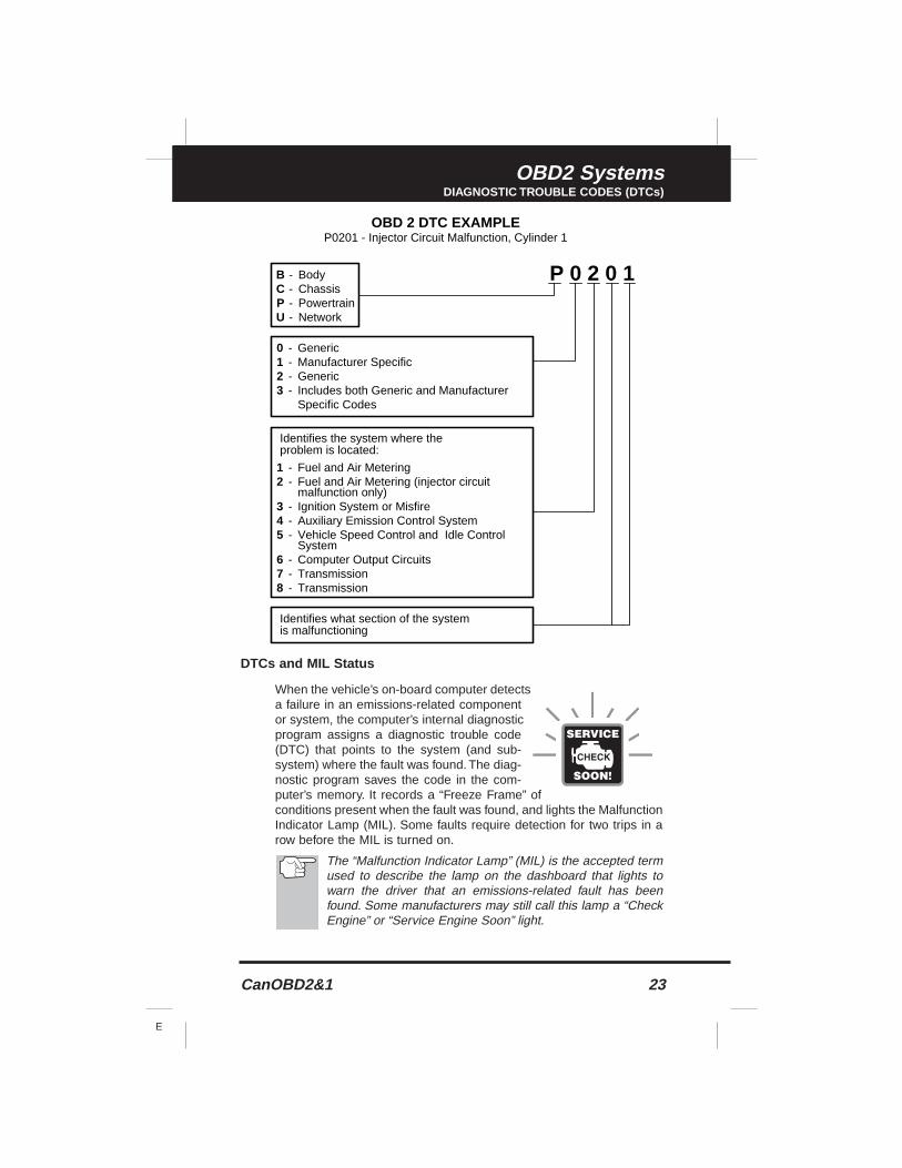
■ The 1st character is a letter . It identifies the “main system” wherethe fault occurred (Body, Chassis, Powertrain, or Network).
■ The 2nd character is a numeric digit . It identifies the “type” of code(Generic or Manufacturer-Specific).
Generic DTCs are codes that are used by all vehicle manu-facturers. The standards for generic DTCs, as well as theirdefinitions, are set by the Society of Automotive Engineers(SAE).
Manufacturer-Specific DTCs are codes that are controlledby the vehicle manufacturers. The Federal Government doesnot require vehicle manufacturers to go beyond the stan-dardized generic DTCs in order to comply with the newOBD2 emissions standards. However, manufacturers are freeto expand beyond the standardized codes to make their sys-tems easier to diagnose.
■ The 3rd character is a numeric digit . It identifies the specific sys-tem or sub-system where the problem is located.
■ The 4th and 5th characters are numeric digits . They identify thesection of the system that is malfunctioning.
Diagnostic TroubleCodes (DTCs) are
codes that identify aspecific problem area.
CanOBD2&1 23
E
OBD2 SystemsDIAGNOSTIC TROUBLE CODES (DTCs)
DTCs and MIL Status
When the vehicle’s on-board computer detectsa failure in an emissions-related componentor system, the computer’s internal diagnosticprogram assigns a diagnostic trouble code(DTC) that points to the system (and sub-system) where the fault was found. The diag-nostic program saves the code in the com-puter’s memory. It records a “Freeze Frame” ofconditions present when the fault was found, and lights the MalfunctionIndicator Lamp (MIL). Some faults require detection for two trips in arow before the MIL is turned on.
The “Malfunction Indicator Lamp” (MIL) is the accepted termused to describe the lamp on the dashboard that lights towarn the driver that an emissions-related fault has beenfound. Some manufacturers may still call this lamp a “CheckEngine” or “Service Engine Soon” light.
P 0 2 0 1BCPU
----
BodyChassisPowertrainNetwork
----
GenericManufacturer SpecificGenericIncludes both Generic and ManufacturerSpecific Codes
0123
Identifies what section of the systemis malfunctioning
Identifies the system where theproblem is located:
12 345 678
--
---
---
Fuel and Air MeteringFuel and Air Metering (injector circuitmalfunction only)Ignition System or MisfireAuxiliary Emission Control SystemVehicle Speed Control and Idle ControlSystemComputer Output CircuitsTransmissionTransmission
OBD 2 DTC EXAMPLEP0201 - Injector Circuit Malfunction, Cylinder 1
24 CanOBD2&1
E
OBD2 SystemsCODE RETRIEVAL PROCEDURE
CODE RETRIEVAL PROCEDURE
Never replace a part based only on the DTC definition.Each DTC has a set of testing procedures, instructionsand flow charts that must be followed to confirm the loca-tion of the problem. This information is found in the vehicle'sservice manual. Always refer to the vehicle's service manualfor detailed testing instructions.
Check your vehicle thoroughly before performingany test. See Before You Begin on page 18 fordetails.
ALWAYS observe safety precautions whenever working on avehicle. See Safety Precautions on page 3 for more infor-mation.
1. Turn the ignition OFF.
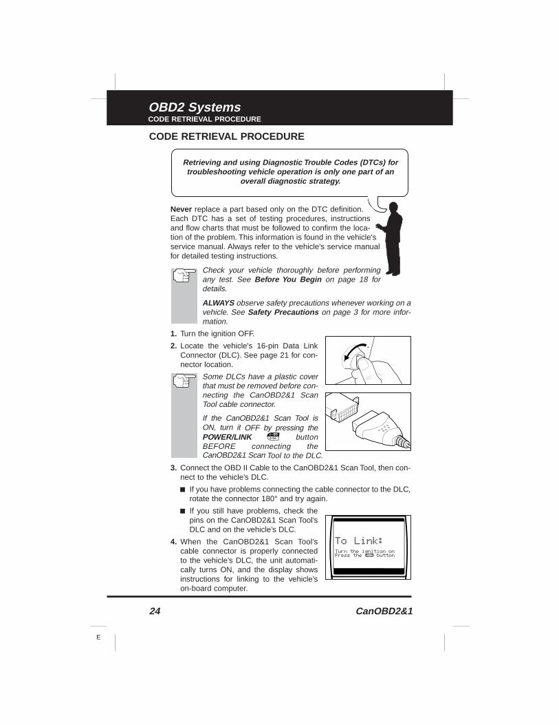
2. Locate the vehicle's 16-pin Data LinkConnector (DLC). See page 21 for con-nector location.
Some DLCs have a plastic coverthat must be removed before con-necting the CanOBD2&1 ScanTool cable connector.
If the CanOBD2&1 Scan Tool isON, turn it OFF by pressing thePOWER/LINK buttonBEFORE connecting theCanOBD2&1 Scan Tool to the DLC.
3. Connect the OBD II Cable to the CanOBD2&1 Scan Tool, then con-nect to the vehicle’s DLC.
■ If you have problems connecting the cable connector to the DLC,rotate the connector 180° and try again.
■ If you still have problems, check thepins on the CanOBD2&1 Scan Tool’sDLC and on the vehicle’s DLC.
4. When the CanOBD2&1 Scan Tool’scable connector is properly connectedto the vehicle’s DLC, the unit automati-cally turns ON, and the display showsinstructions for linking to the vehicle’son-board computer.
Retrieving and using Diagnostic Trouble Codes (DTCs) fortroubleshooting vehicle operation is only one part of an
overall diagnostic strategy.
CanOBD2&1 25
E
OBD2 SystemsCODE RETRIEVAL PROCEDURE
■ If the unit does not power on automatically when connected tothe vehicle’s DLC connector, it usually indicates there is nopower present at the vehicle’s DLC connector. Check your fusepanel and replace any burned-out fuses.
■ If replacing the fuse(s) does not correct the problem, consult yourvehicle’s repair manual to identify the proper computer (PCM) fuse/circuit, and perform any necessary repairs before proceeding.
5. Turn the ignition on. DO NOT start the engine.
6. Press and release the CanOBD2&1 Scan Tool’s POWER/LINKbutton.
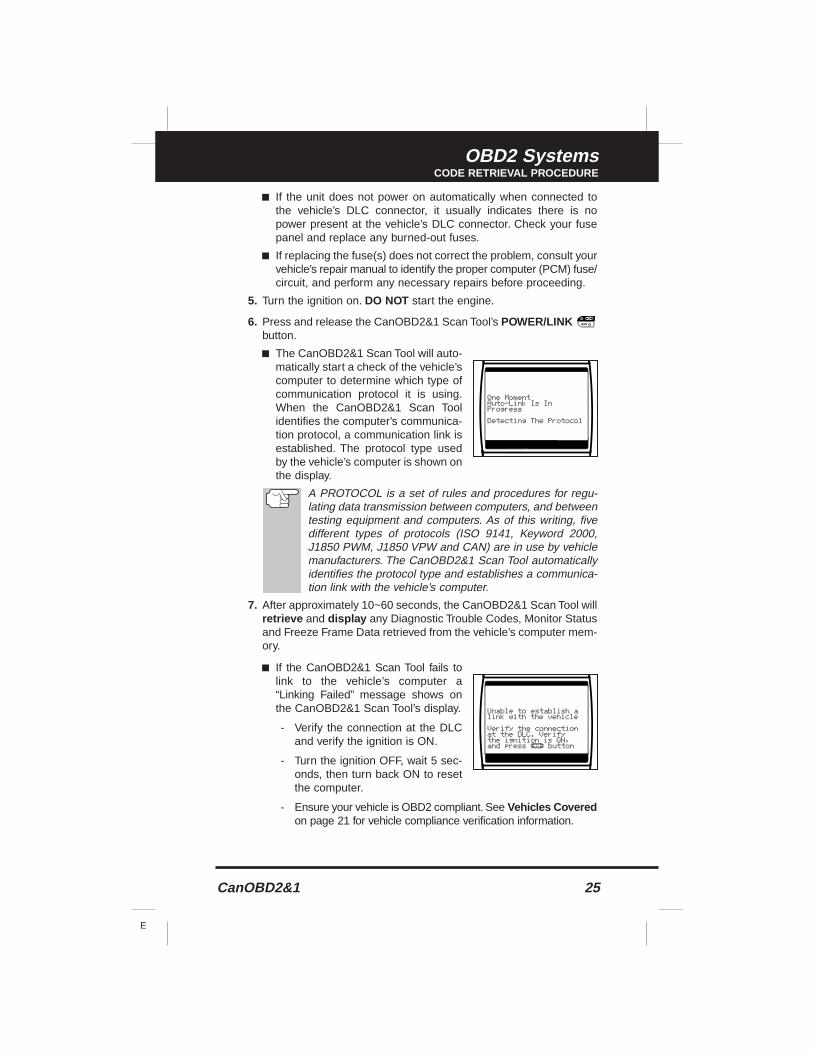
■ The CanOBD2&1 Scan Tool will auto-matically start a check of the vehicle’scomputer to determine which type ofcommunication protocol it is using.When the CanOBD2&1 Scan Toolidentifies the computer’s communica-tion protocol, a communication link isestablished. The protocol type usedby the vehicle’s computer is shown onthe display.
A PROTOCOL is a set of rules and procedures for regu-lating data transmission between computers, and betweentesting equipment and computers. As of this writing, fivedifferent types of protocols (ISO 9141, Keyword 2000,J1850 PWM, J1850 VPW and CAN) are in use by vehiclemanufacturers. The CanOBD2&1 Scan Tool automaticallyidentifies the protocol type and establishes a communica-tion link with the vehicle’s computer.
7. After approximately 10~60 seconds, the CanOBD2&1 Scan Tool willretrieve and display any Diagnostic Trouble Codes, Monitor Statusand Freeze Frame Data retrieved from the vehicle’s computer mem-ory.
■ If the CanOBD2&1 Scan Tool fails tolink to the vehicle’s computer a“Linking Failed” message shows onthe CanOBD2&1 Scan Tool’s display.
- Verify the connection at the DLCand verify the ignition is ON.
- Turn the ignition OFF, wait 5 sec-onds, then turn back ON to resetthe computer.
- Ensure your vehicle is OBD2 compliant. See Vehicles Coveredon page 21 for vehicle compliance verification information.
26 CanOBD2&1
E
OBD2 SystemsCODE RETRIEVAL PROCEDURE
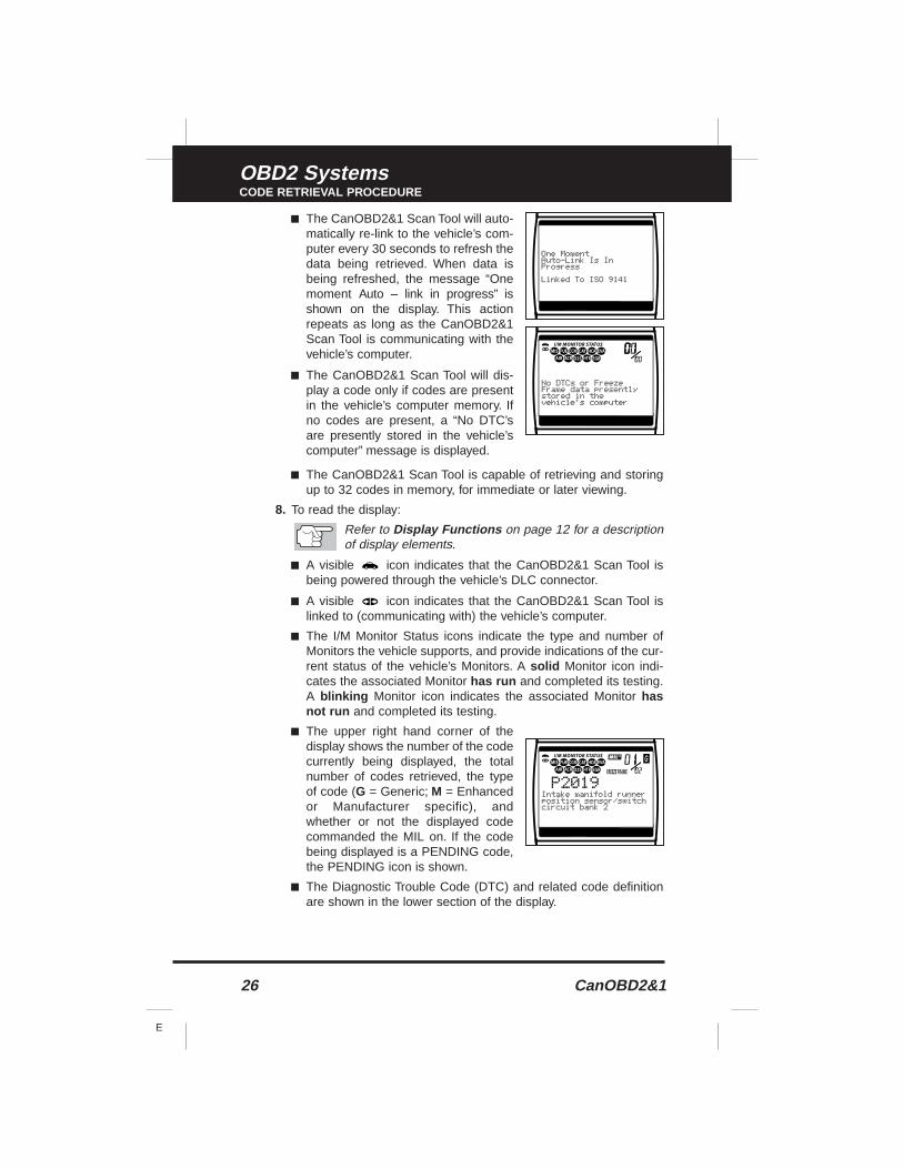
■ The CanOBD2&1 Scan Tool will auto-matically re-link to the vehicle’s com-puter every 30 seconds to refresh thedata being retrieved. When data isbeing refreshed, the message “Onemoment Auto – link in progress” isshown on the display. This actionrepeats as long as the CanOBD2&1Scan Tool is communicating with thevehicle’s computer.
■ The CanOBD2&1 Scan Tool will dis-play a code only if codes are presentin the vehicle’s computer memory. Ifno codes are present, a “No DTC’sare presently stored in the vehicle’scomputer” message is displayed.
■ The CanOBD2&1 Scan Tool is capable of retrieving and storingup to 32 codes in memory, for immediate or later viewing.
8. To read the display:
Refer to Display Functions on page 12 for a descriptionof display elements.
■ A visible icon indicates that the CanOBD2&1 Scan Tool isbeing powered through the vehicle’s DLC connector.
■ A visible icon indicates that the CanOBD2&1 Scan Tool islinked to (communicating with) the vehicle’s computer.
■ The I/M Monitor Status icons indicate the type and number ofMonitors the vehicle supports, and provide indications of the cur-rent status of the vehicle’s Monitors. A solid Monitor icon indi-cates the associated Monitor has run and completed its testing.A blinking Monitor icon indicates the associated Monitor hasnot run and completed its testing.
■ The upper right hand corner of thedisplay shows the number of the codecurrently being displayed, the totalnumber of codes retrieved, the typeof code (G = Generic; M = Enhancedor Manufacturer specific), andwhether or not the displayed codecommanded the MIL on. If the codebeing displayed is a PENDING code,the PENDING icon is shown.
■ The Diagnostic Trouble Code (DTC) and related code definitionare shown in the lower section of the display.
CanOBD2&1 27
E
OBD2 SystemsCODE RETRIEVAL PROCEDURE
In the case of long code definitions, or when viewingFreeze Frame data, a small arrow is shown in theupper/lower right-hand corner of the code display areato indicate the presence of additional information. Usethe and buttons, as necessary, to view the addi-tional information.
9. Read and interpret Diagnostic Trouble Codes/system conditionusing the display and the green, yellow and red LEDs.
The green, yellow and red LEDs are used (with the LCDdisplay) as visual aids to make it easier to determineengine system conditions.
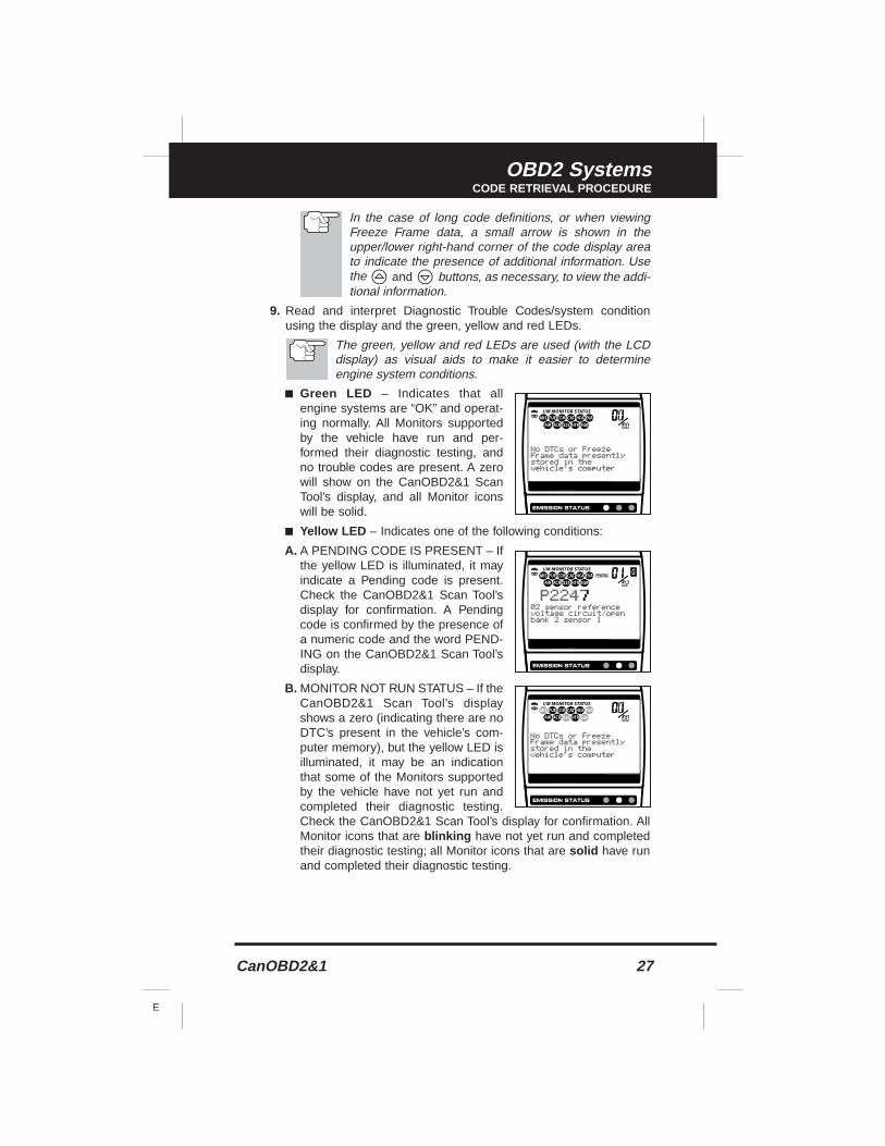
■ Green LED – Indicates that allengine systems are “OK” and operat-ing normally. All Monitors supportedby the vehicle have run and per-formed their diagnostic testing, andno trouble codes are present. A zerowill show on the CanOBD2&1 ScanTool’s display, and all Monitor iconswill be solid.
■ Yellow LED – Indicates one of the following conditions:
A. A PENDING CODE IS PRESENT – Ifthe yellow LED is illuminated, it mayindicate a Pending code is present.Check the CanOBD2&1 Scan Tool’sdisplay for confirmation. A Pendingcode is confirmed by the presence ofa numeric code and the word PEND-ING on the CanOBD2&1 Scan Tool’sdisplay.
B. MONITOR NOT RUN STATUS – If theCanOBD2&1 Scan Tool’s displayshows a zero (indicating there are noDTC’s present in the vehicle’s com-puter memory), but the yellow LED isilluminated, it may be an indicationthat some of the Monitors supportedby the vehicle have not yet run andcompleted their diagnostic testing.Check the CanOBD2&1 Scan Tool’s display for confirmation. AllMonitor icons that are blinking have not yet run and completedtheir diagnostic testing; all Monitor icons that are solid have runand completed their diagnostic testing.
28 CanOBD2&1
E
OBD2 SystemsCODE RETRIEVAL PROCEDURE
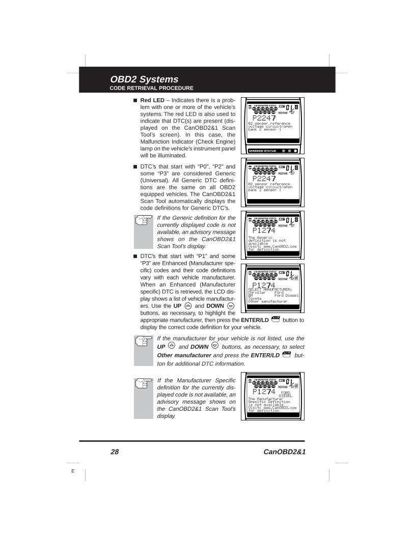
■ Red LED – Indicates there is a prob-lem with one or more of the vehicle’ssystems. The red LED is also used toindicate that DTC(s) are present (dis-played on the CanOBD2&1 ScanTool’s screen). In this case, theMalfunction Indicator (Check Engine)lamp on the vehicle’s instrument panelwill be illuminated.
■ DTC’s that start with “P0”, “P2” andsome “P3” are considered Generic(Universal). All Generic DTC defini-tions are the same on all OBD2equipped vehicles. The CanOBD2&1Scan Tool automatically displays thecode definitions for Generic DTC’s.
If the Generic definition for thecurrently displayed code is notavailable, an advisory messageshows on the CanOBD2&1Scan Tool’s display.
■ DTC’s that start with “P1” and some“P3” are Enhanced (Manufacturer spe-cific) codes and their code definitionsvary with each vehicle manufacturer.When an Enhanced (Manufacturerspecific) DTC is retrieved, the LCD dis-play shows a list of vehicle manufactur-ers. Use the UP and DOWNbuttons, as necessary, to highlight theappropriate manufacturer, then press the ENTER/LD button todisplay the correct code definition for your vehicle.
If the manufacturer for your vehicle is not listed, use theUP and DOWN buttons, as necessary, to selectOther manufacturer and press the ENTER/LD but-ton for additional DTC information.
If the Manufacturer Specificdefinition for the currently dis-played code is not available, anadvisory message shows onthe CanOBD2&1 Scan Tool’sdisplay.
CanOBD2&1 29
E
OBD2 SystemsCODE RETRIEVAL PROCEDURE
10. If more than one code was retrieved press the DTC SCROLLbutton, as necessary, to display additional codes one at a time.
■ Each time the DTC SCROLL button is pressed and released,the CanOBD2&1 Scan Tool will scroll and display the next DTC insequence until all DTCs in its memory have displayed.
■ Freeze Frame Data (if available) will display after DTC #1.
Whenever the Scroll function is used to view additionalcodes, the CanOBD2&1 Scan Tool’s communication linkwith the vehicle’s computer disconnects. To re-establishcommunication, press the POWER/LINK button again.
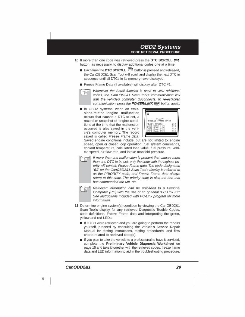
■ In OBD2 systems, when an emis-sions-related engine malfunctionoccurs that causes a DTC to set, arecord or snapshot of engine condi-tions at the time that the malfunctionoccurred is also saved in the vehi-cle’s computer memory. The recordsaved is called Freeze Frame data.Saved engine conditions include, but are not limited to: enginespeed, open or closed loop operation, fuel system commands,coolant temperature, calculated load value, fuel pressure, vehi-cle speed, air flow rate, and intake manifold pressure.
If more than one malfunction is present that causes morethan one DTC to be set, only the code with the highest pri-ority will contain Freeze Frame data. The code designated“01” on the CanOBD2&1 Scan Tool’s display is referred toas the PRIORITY code, and Freeze Frame data alwaysrefers to this code. The priority code is also the one thathas commanded the MIL on.
Retrieved information can be uploaded to a PersonalComputer (PC) with the use of an optional “PC Link Kit.”See instructions included with PC-Link program for moreinformation.
11. Determine engine system(s) condition by viewing the CanOBD2&1Scan Tool’s display for any retrieved Diagnostic Trouble Codes,code definitions, Freeze Frame data and interpreting the green,yellow and red LEDs.
■ If DTC’s were retrieved and you are going to perform the repairsyourself, proceed by consulting the Vehicle’s Service RepairManual for testing instructions, testing procedures, and flowcharts related to retrieved code(s).
■ If you plan to take the vehicle to a professional to have it serviced,complete the Preliminary Vehicle Diagnosis Worksheet onpage 15 and take it together with the retrieved codes, freeze framedata and LED information to aid in the troubleshooting procedure.
30 CanOBD2&1
E
OBD2 SystemsERASING DIAGNOSTIC TROUBLE CODES (DTCs)
■ To prolong battery life, the CanOBD2&1 Scan Tool automaticallyshuts “Off” approximately three minutes after it is disconnectedfrom the vehicle. The DTCs retrieved, Monitor Status and FreezeFrame data (if any) will remain in the CanOBD2&1 Scan Tool’smemory, and may be viewed at any time by turning the unit “On”.If the CanOBD2&1 Scan Tool’s batteries are removed, or if theCanOBD2&1 Scan Tool is re-linked to a vehicle to retrieve codes/data, any prior codes/data in its memory are automatically cleared.
ERASING DIAGNOSTIC TROUBLE CODES (DTCs)
When the CanOBD2&1 Scan Tool’s ERASE function isused to erase DTCs from the vehicle's on-board comput-er, "Freeze Frame" data and manufacturer-specificenhanced data are also erased.
If you plan to take the vehicle to a Service Center for repair, DO NOTerase the codes from the vehicle's computer. If the codes are erased,valuable information that might help the technician troubleshoot theproblem will also be erased.
Erase DTCs from the computer's memory as follows:
When DTCs are erased from the vehicle's computer memo-ry, the I/M Readiness Monitor Status program resets the sta-tus of all Monitors to a not run "flashing" condition. To set allof the Monitors to a DONE status, an OBD 2 Drive Cyclemust be performed. Refer to your vehicle's service manual forinformation on how to perform an OBD 2 Drive Cycle for thevehicle under test.
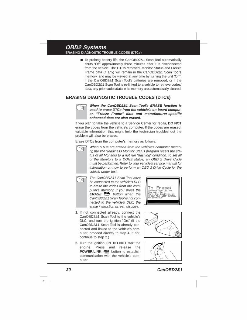
The CanOBD2&1 Scan Tool mustbe connected to the vehicle’s DLCto erase the codes from the com-puter’s memory. If you press theERASE button when theCanOBD2&1 Scan Tool is not con-nected to the vehicle’s DLC, theerase instruction screen displays.
1. If not connected already, connect theCanOBD2&1 Scan Tool to the vehicle'sDLC, and turn the ignition "On.” (If theCanOBD2&1 Scan Tool is already con-nected and linked to the vehicle's com-puter, proceed directly to step 4. If not,continue to step 2.)
2. Turn the ignition ON. DO NOT start theengine. Press and release thePOWER/LINK button to establishcommunication with the vehicle's com-puter.
CanOBD2&1 31
E
OBD2 SystemsI/M READINESS TESTING
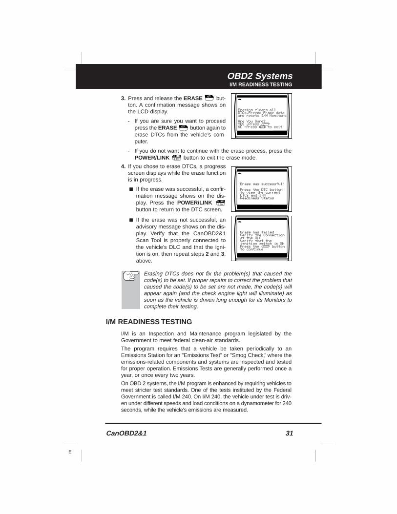
3. Press and release the ERASE but-ton. A confirmation message shows onthe LCD display.
- If you are sure you want to proceedpress the ERASE button again toerase DTCs from the vehicle’s com-puter.
- If you do not want to continue with the erase process, press thePOWER/LINK button to exit the erase mode.
4. If you chose to erase DTCs, a progressscreen displays while the erase functionis in progress.
■ If the erase was successful, a confir-mation message shows on the dis-play. Press the POWER/LINKbutton to return to the DTC screen.
■ If the erase was not successful, anadvisory message shows on the dis-play. Verify that the CanOBD2&1Scan Tool is properly connected tothe vehicle’s DLC and that the igni-tion is on, then repeat steps 2 and 3,above.
Erasing DTCs does not fix the problem(s) that caused thecode(s) to be set. If proper repairs to correct the problem thatcaused the code(s) to be set are not made, the code(s) willappear again (and the check engine light will illuminate) assoon as the vehicle is driven long enough for its Monitors tocomplete their testing.
I/M READINESS TESTING
I/M is an Inspection and Maintenance program legislated by theGovernment to meet federal clean-air standards.
The program requires that a vehicle be taken periodically to anEmissions Station for an "Emissions Test" or "Smog Check,” where theemissions-related components and systems are inspected and testedfor proper operation. Emissions Tests are generally performed once ayear, or once every two years.
On OBD 2 systems, the I/M program is enhanced by requiring vehicles tomeet stricter test standards. One of the tests instituted by the FederalGovernment is called I/M 240. On I/M 240, the vehicle under test is driv-en under different speeds and load conditions on a dynamometer for 240seconds, while the vehicle's emissions are measured.
32 CanOBD2&1
E
OBD2 SystemsI/M READINESS TESTING
Emissions tests vary depending on the geographic or region-al area in which the vehicle is registered. If the vehicle is reg-istered in a highly urbanized area, the I/M 240 is probably thetype of test required. If the vehicle is registered in a rural area,the stricter “dynamometer type” test may not be required.
I/M Readiness Monitors
I/M Readiness shows whether the various emissions-related systemson the vehicle are operating properly and are ready for Inspection andMaintenance testing.
State and Federal Governments enacted Regulations, Procedures andEmission Standards to ensure that all emissions-related componentsand systems are continuously or periodically monitored, tested anddiagnosed whenever the vehicle is in operation. It also requires vehi-cle manufacturers to automatically detect and report any problems orfaults that may increase the vehicle's emissions to an unacceptable level.
The vehicle's emissions control system consists of several compo-nents or sub-systems (Oxygen Sensor, Catalytic Converter, EGR, FuelSystem, etc.) that aid in reducing vehicle emissions.
To have an efficient Vehicle Emission Control System, all the emis-sions-related components and systems must work correctly wheneverthe vehicle is in operation.
To comply with State and Federal Government regulations, vehiclemanufacturers designed a series of special computer programs called"Monitors" that are programmed into the vehicle's computer. Each ofthese Monitors is specifically designed to run tests and diagnostics ona specific emissions-related component or system (Oxygen Sensor,Catalytic Converter, EGR Valve, Fuel System, etc.) to ensure theirproper operation. Currently, there are a maximum of eleven Monitorsavailable for use.
Each Monitor has a specific function to test and diagnoseonly its designated emissions-related component or system.The names of the Monitors (Oxygen Sensor Monitor, CatalystMonitor, EGR Monitor, Misfire Monitor, etc.) describe whichcomponent or system each Monitor is designed to test anddiagnose.
Emissions Inspection and Maintenance (I/M) Readiness
Monitor Status Inf ormation
I/M Readiness Monitor Status shows which of the vehicle's Monitorshave run and completed their diagnosis and testing, and which oneshave not yet run and completed testing and diagnosis of their desig-nated sections of the vehicle's emissions system.
CanOBD2&1 33
E
OBD2 SystemsI/M READINESS TESTING
■ If a Monitor was able to meet all the conditions required to enable itto perform the self-diagnosis and testing of its assigned engine sys-tem, it means the monitor "HAS RUN.”
■ If a Monitor has not yet met all the conditions required for it to per-form the self-diagnosis and testing of its assigned engine system; itmeans the Monitor "HAS NOT RUN.”
The Monitor Run/Not Run status does not show whetheror not a problem exists in a system. Monitor status onlyindicates whether a particular Monitor has or has not runand performed the self-diagnosis and testing of its asso-ciated system.
Performing I/M Readiness Quic k Chec k
When a vehicle first comes from the factory, all Monitors indi-cate a “HAVE RUN” status. This indicates that all Monitorshave run and completed their diagnostic testing. The “HAVERUN” status remains in the computer's memory, unless theDiagnostic Trouble Codes are erased or the vehicle's com-puter memory is cleared.
The CanOBD2&1 Scan Tool allows you to retrieve Monitor/SystemStatus Information to help you determine if the vehicle is ready for anEmissions Test (Smog Check). In addition to retrieving DiagnosticTrouble Codes, the CanOBD2&1 Scan Tool also retrieves MonitorRun/Not Run status. This information is very important since differentareas of the state/country have different emissions laws and regulationsconcerning Monitor Run/Not Run status.
Before an Emissions Test (Smog Check) can be performed, your vehi-cle must meet certain rules, requirements and procedures legislatedby the Federal and state (country) governments where you live.
1. In most areas, one of the requirements that must be met before avehicle is allowed to be Emissions Tested (Smog Checked) is thatthe vehicle does not have any Diagnostic Trouble Codes present(with the exception of PENDING Diagnostic Trouble Codes).
2. In addition to the requirement that no Diagnostic Trouble Codes bepresent, some areas also require that all the Monitors that a partic-ular vehicle supports indicate a "Has Run" status condition beforean Emissions Check may be performed.
3. Other areas may only require that some (but not all) Monitors indi-cate a "Has Run" status before an Emissions Test (Smog Check)may be performed.
34 CanOBD2&1
E
OBD2 SystemsI/M READINESS TESTING
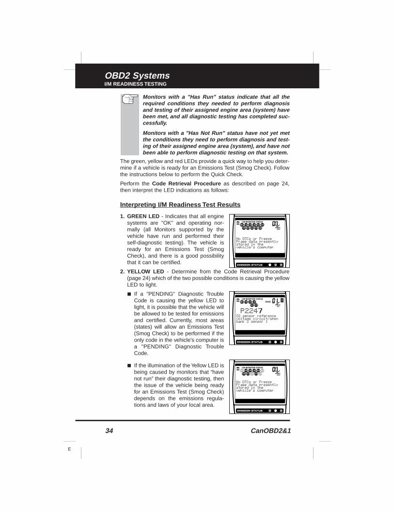
Monitors with a "Has Run" status indicate that all therequired conditions they needed to perform diagnosisand testing of their assigned engine area (system) havebeen met, and all diagnostic testing has completed suc-cessfully.
Monitors with a "Has Not Run" status have not yet metthe conditions they need to perform diagnosis and test-ing of their assigned engine area (system), and have notbeen able to perform diagnostic testing on that system.
The green, yellow and red LEDs provide a quick way to help you deter-mine if a vehicle is ready for an Emissions Test (Smog Check). Followthe instructions below to perform the Quick Check.
Perform the Code Retrieval Procedure as described on page 24,then interpret the LED indications as follows:
Interpreting I/M Readiness Test Results
1. GREEN LED - Indicates that all enginesystems are "OK" and operating nor-mally (all Monitors supported by thevehicle have run and performed theirself-diagnostic testing). The vehicle isready for an Emissions Test (SmogCheck), and there is a good possibilitythat it can be certified.
2. YELLOW LED - Determine from the Code Retrieval Procedure(page 24) which of the two possible conditions is causing the yellowLED to light.
■ If a "PENDING" Diagnostic TroubleCode is causing the yellow LED tolight, it is possible that the vehicle willbe allowed to be tested for emissionsand certified. Currently, most areas(states) will allow an Emissions Test(Smog Check) to be performed if theonly code in the vehicle's computer isa "PENDING" Diagnostic TroubleCode.
■ If the illumination of the Yellow LED isbeing caused by monitors that “havenot run” their diagnostic testing, thenthe issue of the vehicle being readyfor an Emissions Test (Smog Check)depends on the emissions regula-tions and laws of your local area.
CanOBD2&1 35
E
OBD2 SystemsI/M READINESS TESTING
- Some areas require that all Monitors indicate a "Has Run" sta-tus before they allow an Emissions Test (Smog Check) to beperformed. Other areas only require that some, but not all,Monitors have run their self-diagnostic testing before anEmissions Test (Smog Check) may be performed.
From the code retrieval procedure, determine the status ofeach Monitor (a solid Monitor icon shows Monitor "Has Run"status, a flashing Monitor icon indicates "Has Not Run" sta-tus). Take this information to an emissions professional todetermine (based on your test results) if your vehicle is readyfor an Emissions Test (Smog Check).
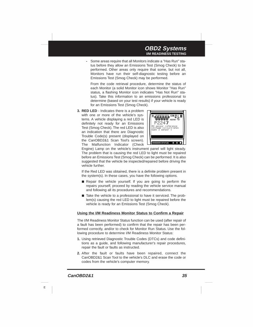
3. RED LED - Indicates there is a problemwith one or more of the vehicle's sys-tems. A vehicle displaying a red LED isdefinitely not ready for an EmissionsTest (Smog Check). The red LED is alsoan indication that there are DiagnosticTrouble Code(s) present (displayed onthe CanOBD2&1 Scan Tool's screen).The Malfunction Indicator (CheckEngine) Lamp on the vehicle's instrument panel will light steady.The problem that is causing the red LED to light must be repairedbefore an Emissions Test (Smog Check) can be performed. It is alsosuggested that the vehicle be inspected/repaired before driving thevehicle further.
If the Red LED was obtained, there is a definite problem present inthe system(s). In these cases, you have the following options.
■ Repair the vehicle yourself. If you are going to perform therepairs yourself, proceed by reading the vehicle service manualand following all its procedures and recommendations.
■ Take the vehicle to a professional to have it serviced. The prob-lem(s) causing the red LED to light must be repaired before thevehicle is ready for an Emissions Test (Smog Check).
Using the I/M Readiness Monitor Status to Confirm a Repair
The I/M Readiness Monitor Status function can be used (after repair ofa fault has been performed) to confirm that the repair has been per-formed correctly, and/or to check for Monitor Run Status. Use the fol-lowing procedure to determine I/M Readiness Monitor Status:
1. Using retrieved Diagnostic Trouble Codes (DTCs) and code defini-tions as a guide, and following manufacturer's repair procedures,repair the fault or faults as instructed.
2. After the fault or faults have been repaired, connect theCanOBD2&1 Scan Tool to the vehicle's DLC and erase the code orcodes from the vehicle's computer memory.
36 CanOBD2&1
E
OBD2 SystemsI/M READINESS TESTING
■ See page 30 for procedures to erase DTCs from the vehicle's on-board computer.
■ Write the codes down on a piece of paper for reference beforeerasing.
3. After the erase procedure is performed, most of the Monitor iconson the CanOBD2&1 Scan Tool’s display will be flashing. Leave theCanOBD2&1 Scan Tool connected to the vehicle, and perform a TripDrive Cycle for each "flashing" Monitor:
Misfire, Fuel and Comprehensive Component Monitors runcontinuously and their icons will always be on solid, evenafter the erase function is performed.
■ Each DTC is associated with a specific Monitor. Consult the vehi-cle's service manual to identify the Monitor (or Monitors) associ-ated with the faults that were repaired. Follow the manufacturer'sprocedures to perform a Trip Drive Cycle for the appropriateMonitors.
■ While observing the Monitor icons on the CanOBD2&1 ScanTool’s display, perform a Trip Drive Cycle for the appropriateMonitor or Monitors.
WARNING: If the vehicle needs to be driven in order to perform aTrip Drive Cycle, ALWAYS have a second person help you. Oneperson should drive the vehicle while the other person observesthe Monitor icons on the CanOBD2&1 Scan Tool for Monitor RUNstatus. Trying to drive and observe the CanOBD2&1 Scan Tool atthe same time is dangerous, and could cause a serious trafficaccident.
4. When a Monitor's Trip Drive Cycle is performed properly, theMonitor icon on the CanOBD2&1 Scan Tool’s display changes from"flashing" to "solid,” indicating that the Monitor has run and finishedits diagnostic testing.
■ If, after the Monitor has run, the MIL on the vehicle's dash is notlit, and no stored or pending codes associated with that particu-lar Monitor are present in the vehicle's computer, the repair wassuccessful.
■ If, after the Monitor has run, the MIL on the vehicle's dash lightsand/or a DTC associated with that Monitor is present in the vehi-cle's computer, the repair was unsuccessful. Refer to the vehi-cle's service manual and recheck repair procedures.
OBD2 Live Data ModeVIEWING LIVE DATA
CanOBD2&1 37
E
The CanOBD2&1 Scan Tool is a special diagnostic tool that communi-cates with the vehicle's computer. The CanOBD2&1 Scan Tool lets youview and/or "capture" (record) "real-time" Live Data. This informationincludes values (volts, rpm, temperature, speed etc.) and system sta-tus information (open loop, closed loop, fuel system status, etc.) gen-erated by the various vehicle sensors, switches and actuators.
In effect the CanOBD2&1 Scan Tool lets you view, in "real time", thesame signal values generated by the sensors, actuators, switches and/orvehicle system status information used by the vehicle's computer whencalculating and conducting system adjustments and corrections.
The real time (Live Data) vehicle operating information (values/status)that the computer supplies to the CanOBD2&1 Scan Tool for each sen-sor, actuator, switch, etc. is called Parameter Identification (PID) Data.
Each PID (sensor, actuator switch, status, etc.) has a set of operatingcharacteristics and features (parameters) that serve to identify it. TheCanOBD2&1 Scan Tool displays this information for each sensor, actu-ator, switch or status that is supported by the vehicle under test.
WARNING: If the vehicle must be driven in order to performa troubleshooting procedure, ALWAYS have a second per-son help you. One person should drive the vehicle while theother person observes the CanOBD2&1 Scan Tool data.Trying to drive and operate the CanOBD2&1 Scan Tool at thesame time is dangerous, and could cause a serious trafficaccident.
VIEWING LIVE DATA
1. Follow steps 1 through 7 of the Code Retrieval Procedure (page 24)to place the CanOBD2&1 Scan Tool in "Code Retrieval" mode.
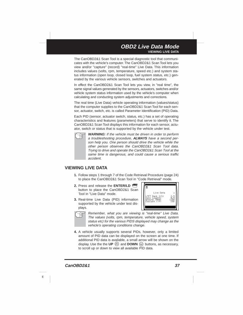
2. Press and release the ENTER/LDbutton to place the CanOBD2&1 ScanTool in "Live Data" mode.
3. Real-time Live Data (PID) informationsupported by the vehicle under test dis-plays.
Remember, what you are viewing is "real-time" Live Data.The values (volts, rpm, temperature, vehicle speed, systemstatus etc) for the various PIDS displayed may change as thevehicle's operating conditions change.
4. A vehicle usually supports several PIDs, however, only a limitedamount of PID data can be displayed on the screen at one time. Ifadditional PID data is available, a small arrow will be shown on thedisplay. Use the the UP and DOWN buttons, as necessary,to scroll up or down to view all available PID data.
OBD2 Live Data ModeCUSTOMIZING LIVE DATA (PIDs)
38 CanOBD2&1
E
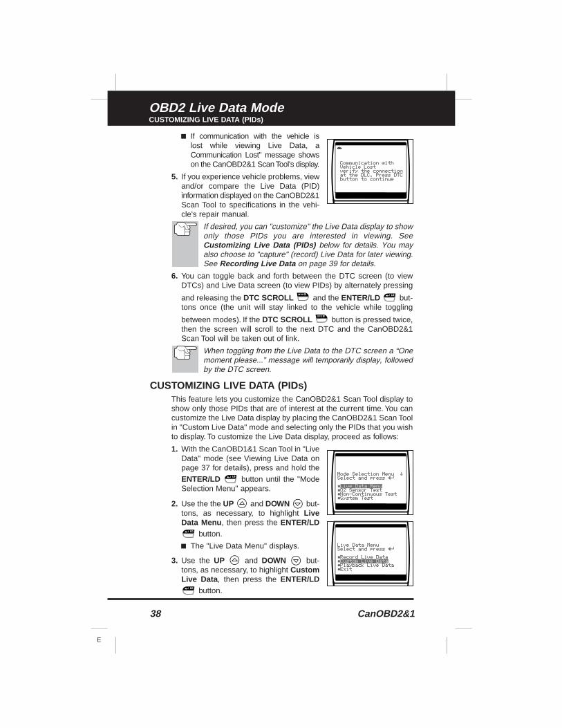
■ If communication with the vehicle is lost while viewing Live Data, aCommunication Lost" message showson the CanOBD2&1 Scan Tool's display.
5. If you experience vehicle problems, viewand/or compare the Live Data (PID)information displayed on the CanOBD2&1Scan Tool to specifications in the vehi-cle's repair manual.
If desired, you can "customize" the Live Data display to showonly those PIDs you are interested in viewing. SeeCustomizing Live Data (PIDs) below for details. You mayalso choose to "capture" (record) Live Data for later viewing.See Recording Live Data on page 39 for details.
6. You can toggle back and forth between the DTC screen (to viewDTCs) and Live Data screen (to view PIDs) by alternately pressing
and releasing the DTC SCROLL and the ENTER/LD but-tons once (the unit will stay linked to the vehicle while toggling
between modes). If the DTC SCROLL button is pressed twice,then the screen will scroll to the next DTC and the CanOBD2&1Scan Tool will be taken out of link.
When toggling from the Live Data to the DTC screen a “Onemoment please...” message will temporarily display, followedby the DTC screen.
CUSTOMIZING LIVE DATA (PIDs)This feature lets you customize the CanOBD2&1 Scan Tool display toshow only those PIDs that are of interest at the current time. You cancustomize the Live Data display by placing the CanOBD2&1 Scan Toolin "Custom Live Data" mode and selecting only the PIDs that you wishto display. To customize the Live Data display, proceed as follows:
1. With the CanOBD1&1 Scan Tool in "LiveData" mode (see Viewing Live Data onpage 37 for details), press and hold the
ENTER/LD button until the "ModeSelection Menu" appears.
2. Use the the UP and DOWN but-tons, as necessary, to highlight LiveData Menu , then press the ENTER/LD
button.
■ The "Live Data Menu" displays.
3. Use the UP and DOWN but-tons, as necessary, to highlight CustomLive Data , then press the ENTER/LD
button.
OBD2 Live Data ModeRECORDING (CAPTURING) LIVE DATA
CanOBD2&1 39
E
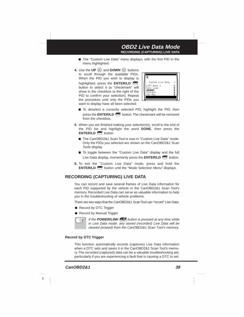
■ The "Custom Live Data" menu displays, with the first PID in themenu highlighted.
4. Use the UP and DOWN buttonsto scroll through the available PIDs.When the PID you wish to display is
highlighted, press the ENTER/LDbutton to select it (a "checkmark" willshow in the checkbox to the right of thePID to confirm your selection). Repeatthe procedure until only the PIDs youwant to display have all been selected.
■ To deselect a currently selected PID, highlight the PID, then
press the ENTER/LD button.The checkmark will be removedfrom the checkbox.
5. When you are finished making your selection(s), scroll to the end ofthe PID list and highlight the word DONE, then press theENTER/LD button.
■ The CanOBD2&1 Scan Tool is now in "Custom Live Data" mode.Only the PIDs you selected are shown on the CanOBD2&1 ScanTools display.
■ To toggle between the "Custom Live Data" display and the full
Live Data display, momentarily press the ENTER/LD button.
6. To exit the "Custom Live Data" mode, press and hold theENTER/LD button until the “Mode Selection Menu” displays.
RECORDING (CAPTURING) LIVE DATA
You can record and save several frames of Live Data information foreach PID supported by the vehicle in the CanOBD2&1 Scan Tool'smemory. Recorded Live Data can serve as valuable information to helpyou in the troubleshooting of vehicle problems.
There are two ways that the CanOBD2&1 Scan Tool can "record" Live Data:
■ Record by DTC Trigger
■ Record by Manual Trigger
If the POWER/LINK button is pressed at any time whilein Live Data mode, any stored (recorded) Live Data will becleared (erased) from the CanOBD2&1 Scan Tool’s memory.
Record by DTC Trigger
This function automatically records (captures) Live Data informationwhen a DTC sets and saves it in the CanOBD2&1 Scan Tool’s memo-ry.The recorded (captured) data can be a valuable troubleshooting aid,particularly if you are experiencing a fault that is causing a DTC to set.
OBD2 Live Data ModeRECORDING (CAPTURING) LIVE DATA
40 CanOBD2&1
E
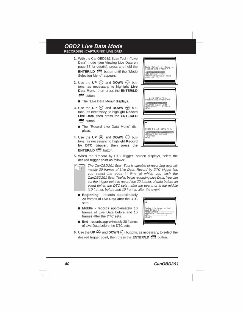
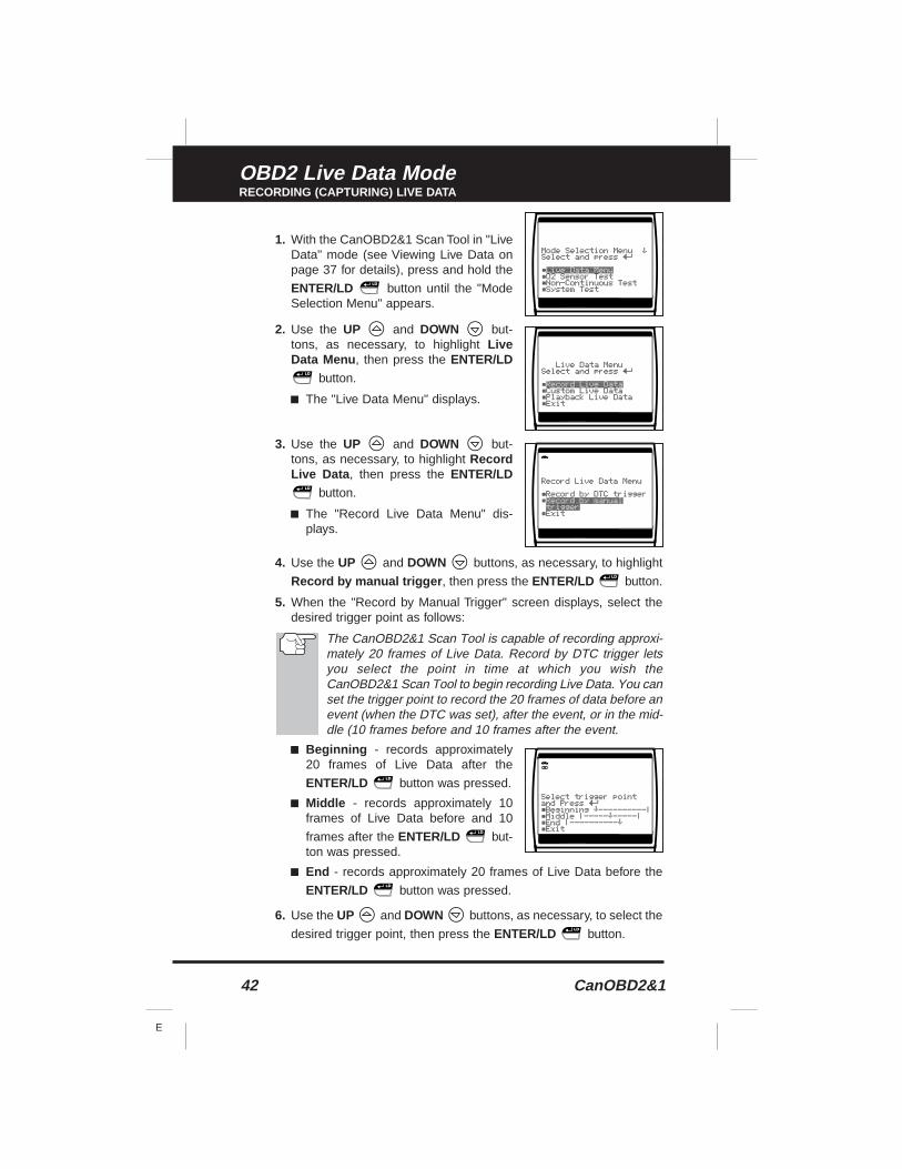
1. With the CanOBD2&1 Scan Tool in "LiveData" mode (see Viewing Live Data onpage 37 for details), press and hold the
ENTER/LD button until the "ModeSelection Menu" appears.
2. Use the UP and DOWN but-tons, as necessary, to highlight LiveData Menu , then press the ENTER/LD
button.
■ The "Live Data Menu" displays.
3. Use the UP and DOWN but-tons, as necessary, to highlight RecordLive Data , then press the ENTER/LD
button.
■ The "Record Live Data Menu" dis-plays.
4. Use the UP and DOWN but-tons, as necessary, to highlight Recordby DTC trigger , then press the
ENTER/LD button.
5. When the "Record by DTC Trigger" screen displays, select thedesired trigger point as follows:
The CanOBD2&1 Scan Tool is capable of recording approxi-mately 20 frames of Live Data. Record by DTC trigger letsyou select the point in time at which you wish theCanOBD2&1 Scan Tool to begin recording Live Data. You canset the trigger point to record the 20 frames of data before anevent (when the DTC sets), after the event, or in the middle(10 frames before and 10 frames after the event.
■ Beginning - records approximately20 frames of Live Data after the DTCsets.
■ Middle - records approximately 10frames of Live Data before and 10frames after the DTC sets.
■ End - records approximately 20 framesof Live Data before the DTC sets.
6. Use the UP and DOWN buttons, as necessary, to select the
desired trigger point, then press the ENTER/LD button.
OBD2 Live Data ModeRECORDING (CAPTURING) LIVE DATA
CanOBD2&1 41
E
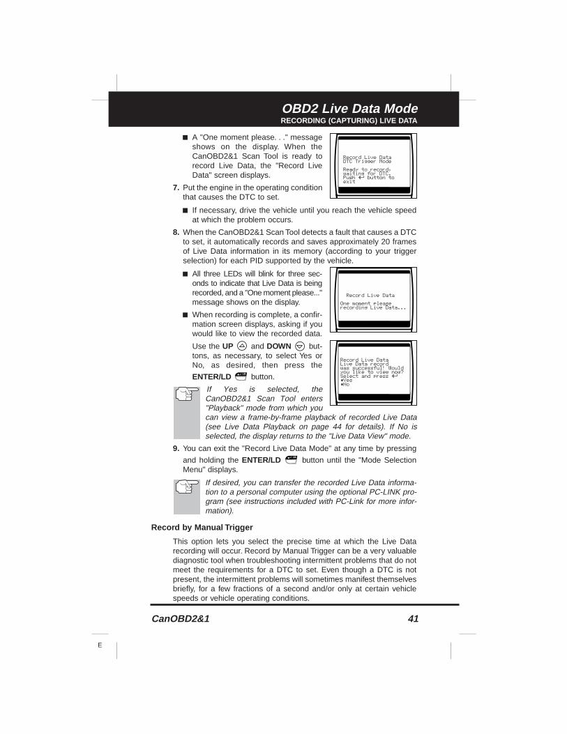
■ A "One moment please. . ." messageshows on the display. When theCanOBD2&1 Scan Tool is ready torecord Live Data, the "Record LiveData" screen displays.
7. Put the engine in the operating conditionthat causes the DTC to set.
■ If necessary, drive the vehicle until you reach the vehicle speedat which the problem occurs.
8. When the CanOBD2&1 Scan Tool detects a fault that causes a DTCto set, it automatically records and saves approximately 20 framesof Live Data information in its memory (according to your triggerselection) for each PID supported by the vehicle.
■ All three LEDs will blink for three sec-onds to indicate that Live Data is beingrecorded, and a "One moment please..."message shows on the display.
■ When recording is complete, a confir-mation screen displays, asking if youwould like to view the recorded data.
Use the UP and DOWN but-tons, as necessary, to select Yes orNo, as desired, then press the
ENTER/LD button.
If Yes is selected, theCanOBD2&1 Scan Tool enters"Playback" mode from which youcan view a frame-by-frame playback of recorded Live Data(see Live Data Playback on page 44 for details). If No isselected, the display returns to the "Live Data View" mode.
9. You can exit the "Record Live Data Mode" at any time by pressing
and holding the ENTER/LD button until the "Mode SelectionMenu" displays.
If desired, you can transfer the recorded Live Data informa-tion to a personal computer using the optional PC-LINK pro-gram (see instructions included with PC-Link for more infor-mation).
Record by Manual Trigger
This option lets you select the precise time at which the Live Datarecording will occur. Record by Manual Trigger can be a very valuablediagnostic tool when troubleshooting intermittent problems that do notmeet the requirements for a DTC to set. Even though a DTC is notpresent, the intermittent problems will sometimes manifest themselvesbriefly, for a few fractions of a second and/or only at certain vehiclespeeds or vehicle operating conditions.
OBD2 Live Data ModeRECORDING (CAPTURING) LIVE DATA
42 CanOBD2&1
E
1. With the CanOBD2&1 Scan Tool in "LiveData" mode (see Viewing Live Data onpage 37 for details), press and hold the
ENTER/LD button until the "ModeSelection Menu" appears.
2. Use the UP and DOWN but-tons, as necessary, to highlight LiveData Menu , then press the ENTER/LD
button.
■ The "Live Data Menu" displays.
3. Use the UP and DOWN but-tons, as necessary, to highlight RecordLive Data , then press the ENTER/LD
button.
■ The "Record Live Data Menu" dis-plays.
4. Use the UP and DOWN buttons, as necessary, to highlight
Record by manual trigger , then press the ENTER/LD button.
5. When the "Record by Manual Trigger" screen displays, select thedesired trigger point as follows:
The CanOBD2&1 Scan Tool is capable of recording approxi-mately 20 frames of Live Data. Record by DTC trigger letsyou select the point in time at which you wish theCanOBD2&1 Scan Tool to begin recording Live Data. You canset the trigger point to record the 20 frames of data before anevent (when the DTC was set), after the event, or in the mid-dle (10 frames before and 10 frames after the event.
■ Beginning - records approximately20 frames of Live Data after the
ENTER/LD button was pressed.
■ Middle - records approximately 10frames of Live Data before and 10
frames after the ENTER/LD but-ton was pressed.
■ End - records approximately 20 frames of Live Data before the
ENTER/LD button was pressed.
6. Use the UP and DOWN buttons, as necessary, to select the
desired trigger point, then press the ENTER/LD button.
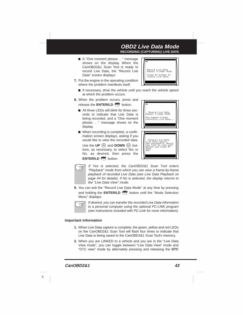
OBD2 Live Data ModeRECORDING (CAPTURING) LIVE DATA
CanOBD2&1 43
E
■ A "One moment please. . ." messageshows on the display. When theCanOBD2&1 Scan Tool is ready torecord Live Data, the "Record LiveData" screen displays.
7. Put the engine in the operating conditionwhere the problem manifests itself.
■ If necessary, drive the vehicle until you reach the vehicle speedat which the problem occurs.
8. When the problem occurs, press and
release the ENTER/LD button.
■ All three LEDs will blink for three sec-onds to indicate that Live Data isbeing recorded, and a "One momentplease. . ." message shows on thedisplay.
■ When recording is complete, a confir-mation screen displays, asking if youwould like to view the recorded data.
Use the UP and DOWN but-tons, as necessary, to select Yes orNo, as desired, then press the
ENTER/LD button.
If Yes is selected, the CanOBD2&1 Scan Tool enters"Playback" mode from which you can view a frame-by-frameplayback of recorded Live Data (see Live Data Playback onpage 44 for details). If No is selected, the display returns tothe "Live Data View" mode.
9. You can exit the "Record Live Data Mode" at any time by pressing
and holding the ENTER/LD button until the "Mode SelectionMenu" displays.
If desired, you can transfer the recorded Live Data informationto a personal computer using the optional PC-LINK program(see instructions included with PC-Link for more information).
Important Information
1. When Live Data capture is complete, the green, yellow and red LEDson the CanOBD2&1 Scan Tool will flash four times to indicate thatLive Data is being saved to the CanOBD2&1 Scan Tool's memory.
2. When you are LINKED to a vehicle and you are in the “Live DataView mode”, you can toggle between “Live Data View” mode and“DTC view” mode by alternately pressing and releasing the DTC
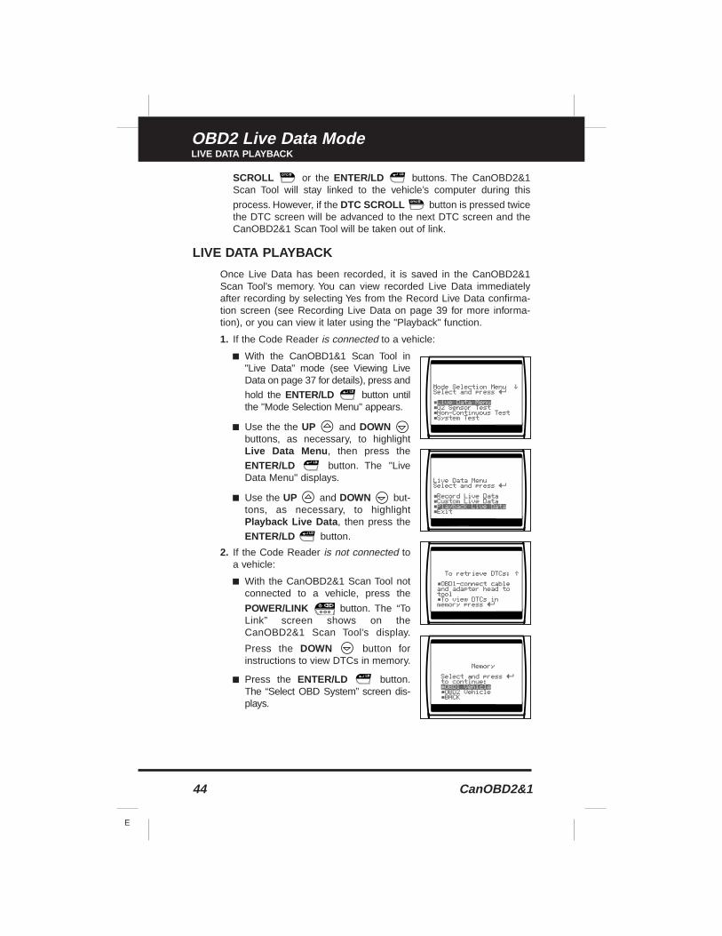
OBD2 Live Data ModeLIVE DATA PLAYBACK
44 CanOBD2&1
E
SCROLL or the ENTER/LD buttons. The CanOBD2&1Scan Tool will stay linked to the vehicle’s computer during this
process. However, if the DTC SCROLL button is pressed twicethe DTC screen will be advanced to the next DTC screen and theCanOBD2&1 Scan Tool will be taken out of link.
LIVE DATA PLAYBACK
Once Live Data has been recorded, it is saved in the CanOBD2&1Scan Tool's memory. You can view recorded Live Data immediatelyafter recording by selecting Yes from the Record Live Data confirma-tion screen (see Recording Live Data on page 39 for more informa-tion), or you can view it later using the "Playback" function.
1. If the Code Reader is connected to a vehicle:
■ With the CanOBD1&1 Scan Tool in"Live Data" mode (see Viewing LiveData on page 37 for details), press and
hold the ENTER/LD button untilthe "Mode Selection Menu" appears.
■ Use the the UP and DOWNbuttons, as necessary, to highlightLive Data Menu , then press the
ENTER/LD button. The "LiveData Menu" displays.
■ Use the UP and DOWN but-tons, as necessary, to highlightPlayback Live Data , then press the
ENTER/LD button.
2. If the Code Reader is not connected toa vehicle:
■ With the CanOBD2&1 Scan Tool notconnected to a vehicle, press the
POWER/LINK button. The “ToLink” screen shows on theCanOBD2&1 Scan Tool’s display.
Press the DOWN button forinstructions to view DTCs in memory.
■ Press the ENTER/LD button.The “Select OBD System” screen dis-plays.
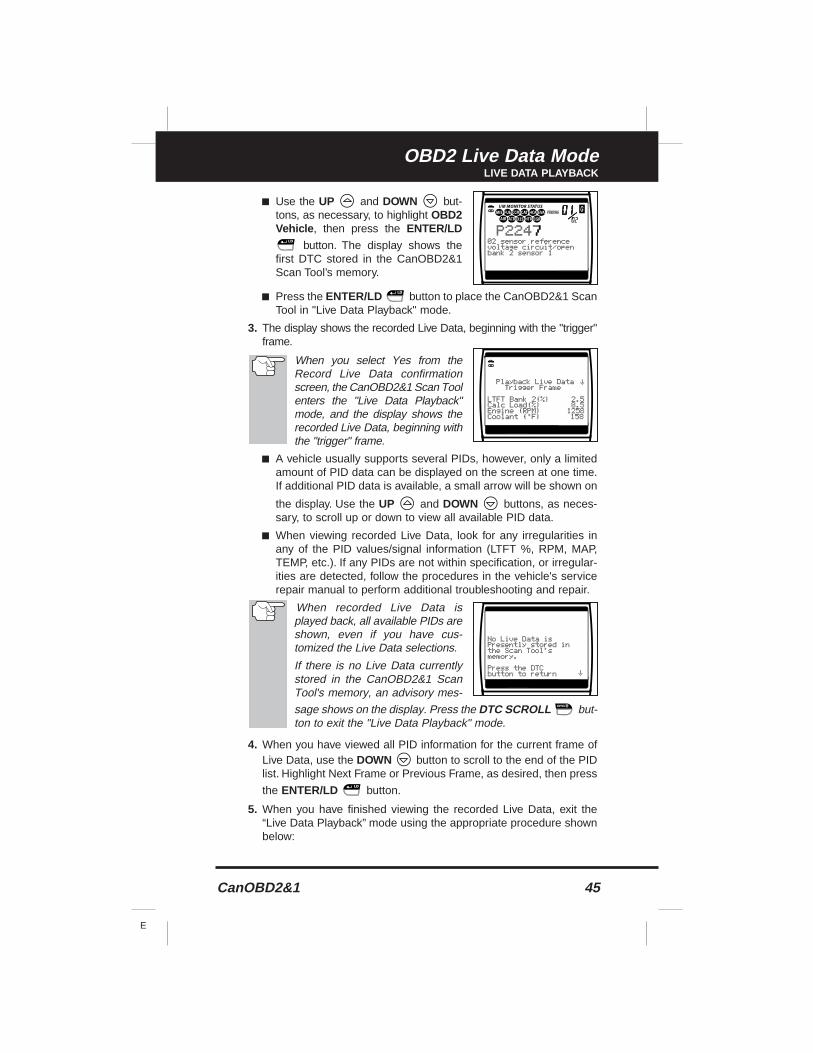
OBD2 Live Data ModeLIVE DATA PLAYBACK
CanOBD2&1 45
E
■ Use the UP and DOWN but-tons, as necessary, to highlight OBD2Vehicle , then press the ENTER/LD
button. The display shows thefirst DTC stored in the CanOBD2&1Scan Tool’s memory.
■ Press the ENTER/LD button to place the CanOBD2&1 ScanTool in "Live Data Playback" mode.
3. The display shows the recorded Live Data, beginning with the "trigger"frame.
When you select Yes from theRecord Live Data confirmationscreen, the CanOBD2&1 Scan Toolenters the "Live Data Playback"mode, and the display shows therecorded Live Data, beginning withthe "trigger" frame.
■ A vehicle usually supports several PIDs, however, only a limitedamount of PID data can be displayed on the screen at one time.If additional PID data is available, a small arrow will be shown on
the display. Use the UP and DOWN buttons, as neces-sary, to scroll up or down to view all available PID data.
■ When viewing recorded Live Data, look for any irregularities inany of the PID values/signal information (LTFT %, RPM, MAP,TEMP, etc.). If any PIDs are not within specification, or irregular-ities are detected, follow the procedures in the vehicle's servicerepair manual to perform additional troubleshooting and repair.
When recorded Live Data isplayed back, all available PIDs areshown, even if you have cus-tomized the Live Data selections.
If there is no Live Data currentlystored in the CanOBD2&1 ScanTool's memory, an advisory mes-
sage shows on the display. Press the DTC SCROLL but-ton to exit the "Live Data Playback" mode.
4. When you have viewed all PID information for the current frame ofLive Data, use the DOWN button to scroll to the end of the PIDlist. Highlight Next Frame or Previous Frame, as desired, then press
the ENTER/LD button.
5. When you have finished viewing the recorded Live Data, exit the“Live Data Playback” mode using the appropriate procedure shownbelow:
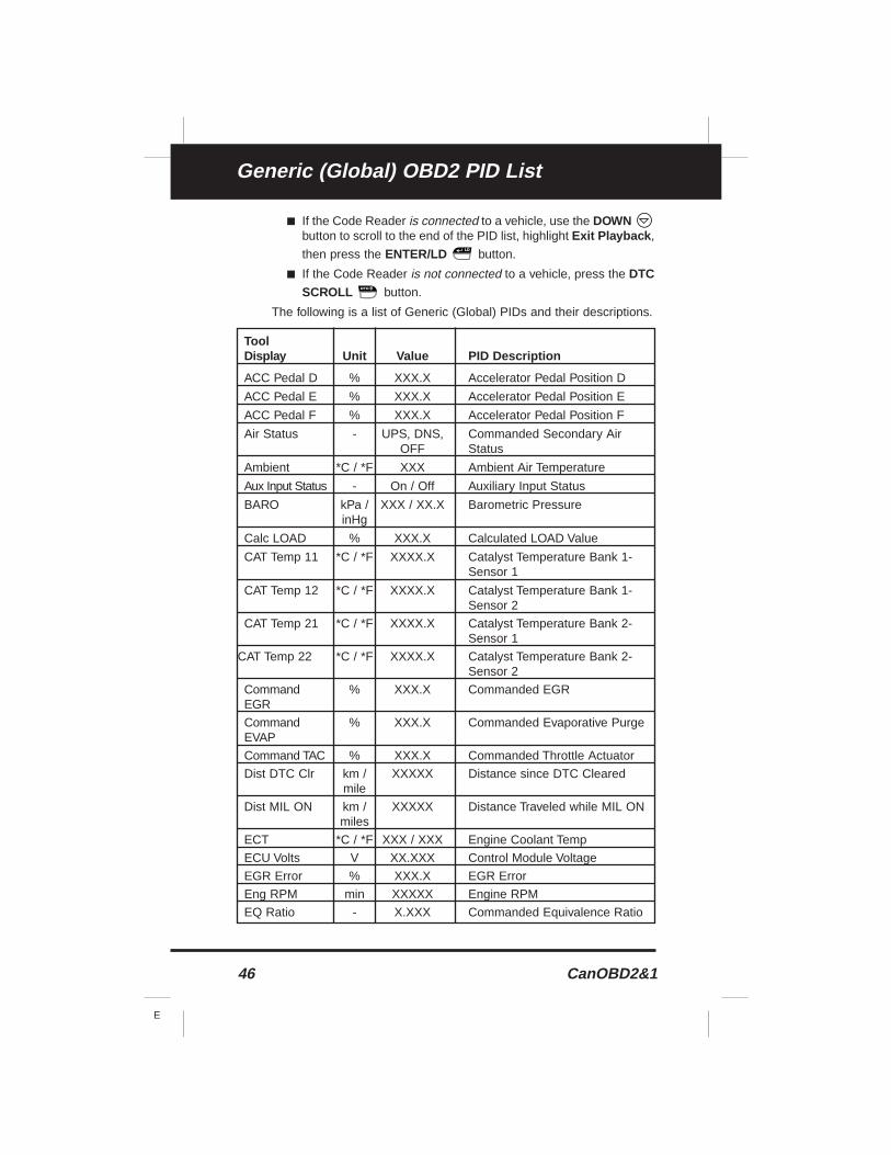
Generic (Global) OBD2 PID List
46 CanOBD2&1
E
■ If the Code Reader is connected to a vehicle, use the DOWNbutton to scroll to the end of the PID list, highlight Exit Playback ,
then press the ENTER/LD button.
■ If the Code Reader is not connected to a vehicle, press the DTCSCROLL button.
The following is a list of Generic (Global) PIDs and their descriptions.
ToolDisplay Unit Value PID Description
ACC Pedal D % XXX.X Accelerator Pedal Position D
ACC Pedal E % XXX.X Accelerator Pedal Position E
ACC Pedal F % XXX.X Accelerator Pedal Position F
Air Status - UPS, DNS, Commanded Secondary Air OFF Status
Ambient *C / *F XXX Ambient Air Temperature
Aux Input Status - On / Off Auxiliary Input Status
BARO kPa / XXX / XX.X Barometric PressureinHg
Calc LOAD % XXX.X Calculated LOAD Value
CAT Temp 11 *C / *F XXXX.X Catalyst Temperature Bank 1- Sensor 1
CAT Temp 12 *C / *F XXXX.X Catalyst Temperature Bank 1- Sensor 2
CAT Temp 21 *C / *F XXXX.X Catalyst Temperature Bank 2- Sensor 1
CAT Temp 22 *C / *F XXXX.X Catalyst Temperature Bank 2- Sensor 2
Command % XXX.X Commanded EGREGR
Command % XXX.X Commanded Evaporative PurgeEVAP
Command TAC % XXX.X Commanded Throttle Actuator
Dist DTC Clr km / XXXXX Distance since DTC Clearedmile
Dist MIL ON km / XXXXX Distance Traveled while MIL ONmiles
ECT *C / *F XXX / XXX Engine Coolant Temp
ECU Volts V XX.XXX Control Module Voltage
EGR Error % XXX.X EGR Error
Eng RPM min XXXXX Engine RPM
EQ Ratio - X.XXX Commanded Equivalence Ratio
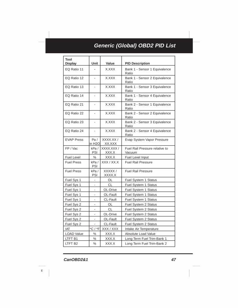
CanOBD2&1 47
E
Generic (Global) OBD2 PID List
ToolDisplay Unit Value PID Description
EQ Ratio 11 - X.XXX Bank 1 - Sensor 1 Equivalence Ratio
EQ Ratio 12 - X.XXX Bank 1 - Sensor 2 Equivalence Ratio
EQ Ratio 13 - X.XXX Bank 1 - Sensor 3 Equivalence Ratio
EQ Ratio 14 - X.XXX Bank 1 - Sensor 4 Equivalence Ratio
EQ Ratio 21 - X.XXX Bank 2 - Sensor 1 Equivalence Ratio
EQ Ratio 22 - X.XXX Bank 2 - Sensor 2 Equivalence Ratio
EQ Ratio 23 - X.XXX Bank 2 - Sensor 3 Equivalence Ratio
EQ Ratio 24 - X.XXX Bank 2 - Sensor 4 Equivalence Ratio
EVAP Press Pa / XXXX.XX / Evap System Vapor Pressurein H2O XX.XXX
FP / Vac kPa / XXXX.XXX / Fuel Rail Pressure relative toPSI XXX.X Vacuum
Fuel Level % XXX.X Fuel Level Input
Fuel Press kPa / XXX / XX.X Fuel Rail PressurePSI
Fuel Press kPa / XXXXX / Fuel Rail PressurePSI XXXX.X
Fuel Sys 1 - OL Fuel System 1 Status
Fuel Sys 1 - CL Fuel System 1 Status
Fuel Sys 1 - OL-Drive Fuel System 1 Status
Fuel Sys 1 - OL-Fault Fuel System 1 Status
Fuel Sys 1 - CL-Fault Fuel System 1 Status
Fuel Sys 2 - OL Fuel System 2 Status
Fuel Sys 2 - CL Fuel System 2 Status
Fuel Sys 2 - OL-Drive Fuel System 2 Status
Fuel Sys 2 - OL-Fault Fuel System 2 Status
Fuel Sys 2 - CL-Fault Fuel System 2 Status
IAT *C / *F XXX / XXX Intake Air Temperature
LOAD Value % XXX.X Absolute Load Value
LTFT B1 % XXX.X Long Term Fuel Trim-Bank 1
LTFT B2 % XXX.X Long Term Fuel Trim-Bank 2
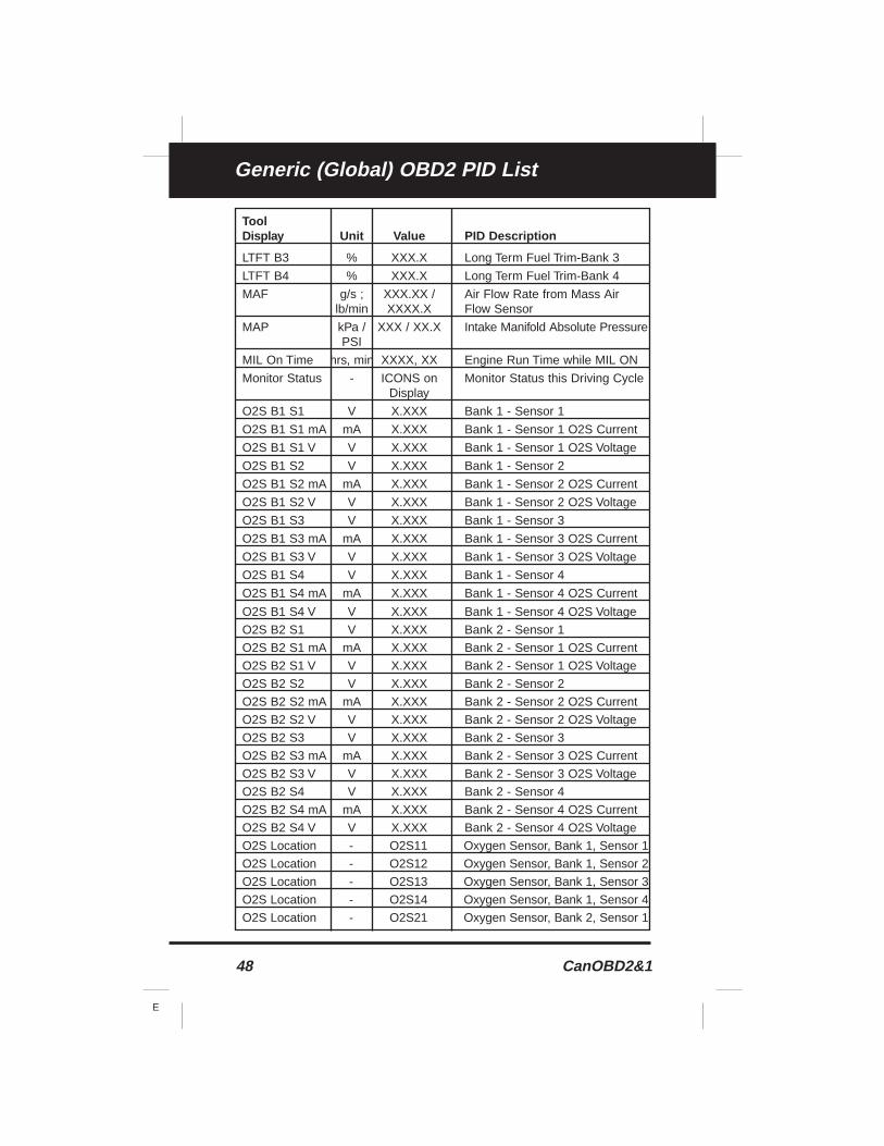
48 CanOBD2&1
E
Generic (Global) OBD2 PID List
ToolDisplay Unit Value PID Description
LTFT B3 % XXX.X Long Term Fuel Trim-Bank 3
LTFT B4 % XXX.X Long Term Fuel Trim-Bank 4
MAF g/s ; XXX.XX / Air Flow Rate from Mass Air lb/min XXXX.X Flow Sensor
MAP kPa / XXX / XX.X Intake Manifold Absolute PressurePSI
MIL On Time hrs, min XXXX, XX Engine Run Time while MIL ON
Monitor Status - ICONS on Monitor Status this Driving CycleDisplay
O2S B1 S1 V X.XXX Bank 1 - Sensor 1
O2S B1 S1 mA mA X.XXX Bank 1 - Sensor 1 O2S Current
O2S B1 S1 V V X.XXX Bank 1 - Sensor 1 O2S Voltage
O2S B1 S2 V X.XXX Bank 1 - Sensor 2
O2S B1 S2 mA mA X.XXX Bank 1 - Sensor 2 O2S Current
O2S B1 S2 V V X.XXX Bank 1 - Sensor 2 O2S Voltage
O2S B1 S3 V X.XXX Bank 1 - Sensor 3
O2S B1 S3 mA mA X.XXX Bank 1 - Sensor 3 O2S Current
O2S B1 S3 V V X.XXX Bank 1 - Sensor 3 O2S Voltage
O2S B1 S4 V X.XXX Bank 1 - Sensor 4
O2S B1 S4 mA mA X.XXX Bank 1 - Sensor 4 O2S Current
O2S B1 S4 V V X.XXX Bank 1 - Sensor 4 O2S Voltage
O2S B2 S1 V X.XXX Bank 2 - Sensor 1
O2S B2 S1 mA mA X.XXX Bank 2 - Sensor 1 O2S Current
O2S B2 S1 V V X.XXX Bank 2 - Sensor 1 O2S Voltage
O2S B2 S2 V X.XXX Bank 2 - Sensor 2
O2S B2 S2 mA mA X.XXX Bank 2 - Sensor 2 O2S Current
O2S B2 S2 V V X.XXX Bank 2 - Sensor 2 O2S Voltage
O2S B2 S3 V X.XXX Bank 2 - Sensor 3
O2S B2 S3 mA mA X.XXX Bank 2 - Sensor 3 O2S Current
O2S B2 S3 V V X.XXX Bank 2 - Sensor 3 O2S Voltage
O2S B2 S4 V X.XXX Bank 2 - Sensor 4
O2S B2 S4 mA mA X.XXX Bank 2 - Sensor 4 O2S Current
O2S B2 S4 V V X.XXX Bank 2 - Sensor 4 O2S Voltage
O2S Location - O2S11 Oxygen Sensor, Bank 1, Sensor 1
O2S Location - O2S12 Oxygen Sensor, Bank 1, Sensor 2
O2S Location - O2S13 Oxygen Sensor, Bank 1, Sensor 3
O2S Location - O2S14 Oxygen Sensor, Bank 1, Sensor 4
O2S Location - O2S21 Oxygen Sensor, Bank 2, Sensor 1
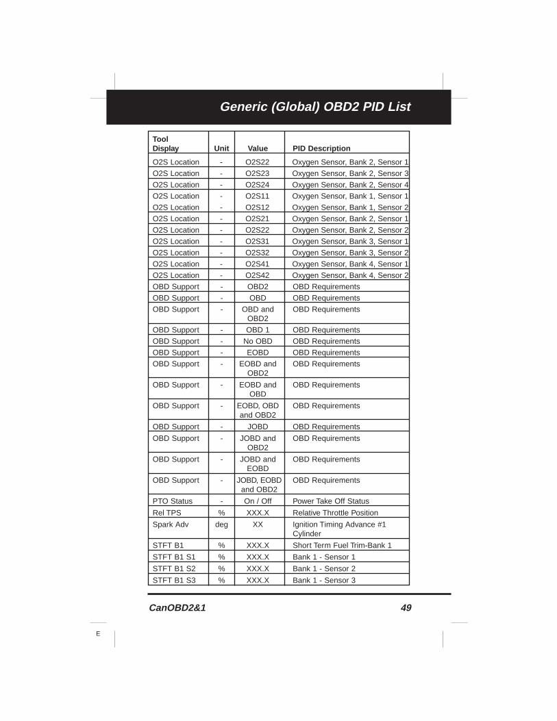
CanOBD2&1 49
E
Generic (Global) OBD2 PID List
ToolDisplay Unit Value PID Description
O2S Location - O2S22 Oxygen Sensor, Bank 2, Sensor 1
O2S Location - O2S23 Oxygen Sensor, Bank 2, Sensor 3
O2S Location - O2S24 Oxygen Sensor, Bank 2, Sensor 4
O2S Location - O2S11 Oxygen Sensor, Bank 1, Sensor 1
O2S Location - O2S12 Oxygen Sensor, Bank 1, Sensor 2
O2S Location - O2S21 Oxygen Sensor, Bank 2, Sensor 1
O2S Location - O2S22 Oxygen Sensor, Bank 2, Sensor 2
O2S Location - O2S31 Oxygen Sensor, Bank 3, Sensor 1
O2S Location - O2S32 Oxygen Sensor, Bank 3, Sensor 2
O2S Location - O2S41 Oxygen Sensor, Bank 4, Sensor 1
O2S Location - O2S42 Oxygen Sensor, Bank 4, Sensor 2
OBD Support - OBD2 OBD Requirements
OBD Support - OBD OBD Requirements
OBD Support - OBD and OBD RequirementsOBD2
OBD Support - OBD 1 OBD Requirements
OBD Support - No OBD OBD Requirements
OBD Support - EOBD OBD Requirements
OBD Support - EOBD and OBD RequirementsOBD2
OBD Support - EOBD and OBD RequirementsOBD
OBD Support - EOBD, OBD OBD Requirementsand OBD2
OBD Support - JOBD OBD Requirements
OBD Support - JOBD and OBD RequirementsOBD2
OBD Support - JOBD and OBD RequirementsEOBD
OBD Support - JOBD, EOBD OBD Requirementsand OBD2
PTO Status - On / Off Power Take Off Status
Rel TPS % XXX.X Relative Throttle Position
Spark Adv deg XX Ignition Timing Advance #1 Cylinder
STFT B1 % XXX.X Short Term Fuel Trim-Bank 1
STFT B1 S1 % XXX.X Bank 1 - Sensor 1
STFT B1 S2 % XXX.X Bank 1 - Sensor 2
STFT B1 S3 % XXX.X Bank 1 - Sensor 3
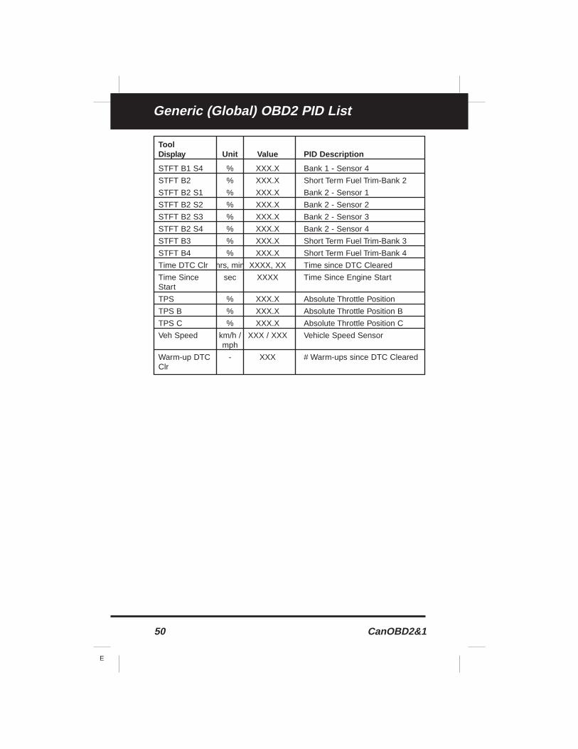
50 CanOBD2&1
E
Generic (Global) OBD2 PID List
ToolDisplay Unit Value PID Description
STFT B1 S4 % XXX.X Bank 1 - Sensor 4
STFT B2 % XXX.X Short Term Fuel Trim-Bank 2
STFT B2 S1 % XXX.X Bank 2 - Sensor 1
STFT B2 S2 % XXX.X Bank 2 - Sensor 2
STFT B2 S3 % XXX.X Bank 2 - Sensor 3
STFT B2 S4 % XXX.X Bank 2 - Sensor 4
STFT B3 % XXX.X Short Term Fuel Trim-Bank 3
STFT B4 % XXX.X Short Term Fuel Trim-Bank 4
Time DTC Clr hrs, min XXXX, XX Time since DTC Cleared
Time Since sec XXXX Time Since Engine StartStart
TPS % XXX.X Absolute Throttle Position
TPS B % XXX.X Absolute Throttle Position B
TPS C % XXX.X Absolute Throttle Position C
Veh Speed km/h / XXX / XXX Vehicle Speed Sensormph
Warm-up DTC - XXX # Warm-ups since DTC ClearedClr
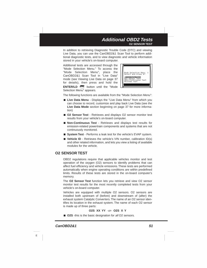
CanOBD2&1 51
E
Additional OBD2 TestsO2 SENSOR TEST
In addition to retrieving Diagnostic Trouble Code (DTC) and viewingLive Data, you can use the CanOBD2&1 Scan Tool to perform addi-tional diagnostic tests, and to view diagnostic and vehicle informationstored in your vehicle's on-board computer.
Additional tests are accessed through the"Mode Selection Menu." To access the"Mode Selection Menu", place theCanOBD2&1 Scan Tool in "Live Data"mode (see Viewing Live Data on page 37for details), then press and hold the
ENTER/LD button until the "ModeSelection Menu" appears.
The following functions are available from the "Mode Selection Menu":
■ Live Data Menu - Displays the "Live Data Menu" from which youcan choose to record, customize and play back Live Data (see theLive Data Mode section beginning on page 37 for more informa-tion)
■ O2 Sensor Test - Retrieves and displays O2 sensor monitor testresults from your vehicle's on-board computer.
■ Non-Continuous Test - Retrieves and displays test results foremission-related powertrain components and systems that are notcontinuously monitored.
■ System Test - Performs a leak test for the vehicle's EVAP system.
■ Vehicle ID - Retrieves the vehicle's VIN number, calibration ID(s)and other related information, and lets you view a listing of availablemodules for the vehicle.
O2 SENSOR TEST
OBD2 regulations require that applicable vehicles monitor and testoperation of the oxygen (O2) sensors to identify problems that canaffect fuel efficiency and vehicle emissions. These tests are performedautomatically when engine operating conditions are within predefinedlimits. Results of these tests are stored in the on-board computer'smemory.
The O2 Sensor Test function lets you retrieve and view O2 sensormonitor test results for the most recently completed tests from yourvehicle's on-board computer.
Vehicles are equipped with multiple O2 sensors. O2 sensors areinstalled both upstream of (before) and downstream of (after) theexhaust system Catalytic Converters. The name of an O2 sensor iden-tifies its location in the exhaust system. The name of each O2 sensoris made up of three parts:
O2S XX YY -or- O2S X Y
■ O2S -this is the basic designation for all O2 sensors.
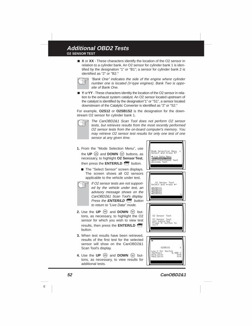
52 CanOBD2&1
E
Additional OBD2 TestsO2 SENSOR TEST
■ X or XX - These characters identify the location of the O2 sensor inrelation to a cylinder bank. An O2 sensor for cylinder bank 1 is iden-tified by the designation “1” or "B1"; a sensor for cylinder bank 2 isidentified as “2” or "B2."
”Bank One” indicates the side of the engine where cylindernumber one is located (V-type engines). Bank Two is oppo-site of Bank One.
■ Y orYY - These characters identity the location of the O2 sensor in rela-tion to the exhaust system catalyst. An O2 sensor located upstream ofthe catalyst is identified by the designation”1” or "S1", a sensor locateddownstream of the Catalytic Converter is identified as “2” or "S2."
For example, O2S12 or O2SB1S2 is the designation for the down-stream O2 sensor for cylinder bank 1.
The CanOBD2&1 Scan Tool does not perform O2 sensortests, but retrieves results from the most recently performedO2 sensor tests from the on-board computer's memory. Youmay retrieve O2 sensor test results for only one test of onesensor at any given time.
1. From the "Mode Selection Menu", use
the UP and DOWN buttons, asnecessary, to highlight O2 Sensor Test ,
then press the ENTER/LD button.
■ The "Select Sensor" screen displays.The screen shows all O2 sensorsapplicable to the vehicle under test.
If O2 sensor tests are not support-ed by the vehicle under test, anadvisory message shows on theCanOBD2&1 Scan Tool's display.Press the ENTER/LD buttonto return to "Live Data" mode.
2. Use the UP and DOWN but-tons, as necessary, to highlight the O2sensor for which you wish to view test
results, then press the ENTER/LDbutton.
3. When test results have been retrieved,results of the first test for the selectedsensor will show on the CanOBD2&1Scan Tool's display.
4. Use the UP and DOWN but-tons, as necessary, to view results foradditional tests.
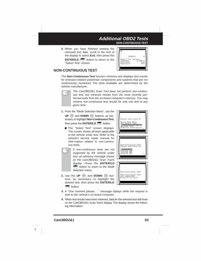
CanOBD2&1 53
E
Additional OBD2 TestsNON-CONTINUOUS TEST
5. When you have finished viewing theretrieved test data, scroll to the end ofthe display to select Exit , then press the
ENTER/LD button to return to the"Select Test" screen.
NON-CONTINUOUS TEST
The Non-Continuous Test function retrieves and displays test resultsfor emission-related powertrain components and systems that are notcontinuously monitored. The tests available are determined by thevehicle manufacturer.
The CanOBD2&1 Scan Tool does not perform non-continu-ous test, but retrieves results from the most recently per-formed tests from the on-board computer’s memory. You mayretrieve non-continuous test results for only one test at anygiven time.
1. From the "Mode Selection Menu", use the
UP and DOWN buttons, as nec-essary, to highlight Non-Continuous Test ,
then press the ENTER/LD button.
■ The “Select Test” screen displays.The screen shows all tests applicableto the vehicle under test. Refer to thevehicle’s service repair manual forinfor-mation related to non-continu-ous tests.
If non-continuous tests are notsupported by the vehicle undertest, an advisory message showson the CanOBD2&1 Scan Tool'sdisplay. Press the ENTER/LD
button to return to the ModeSelection menu.
2. Use the UP and DOWN but-tons, as necessary, to highlight thedesired test, then press the ENTER/LD
button.
3. A “One moment please. . .” message diplays while the request issent to the vehicle’s on-board computer.
4. When test results have been retrieved, data for the selected test will showon the CanOBD2&1 Scan Tool’s display. The display shows the follow-ing information:
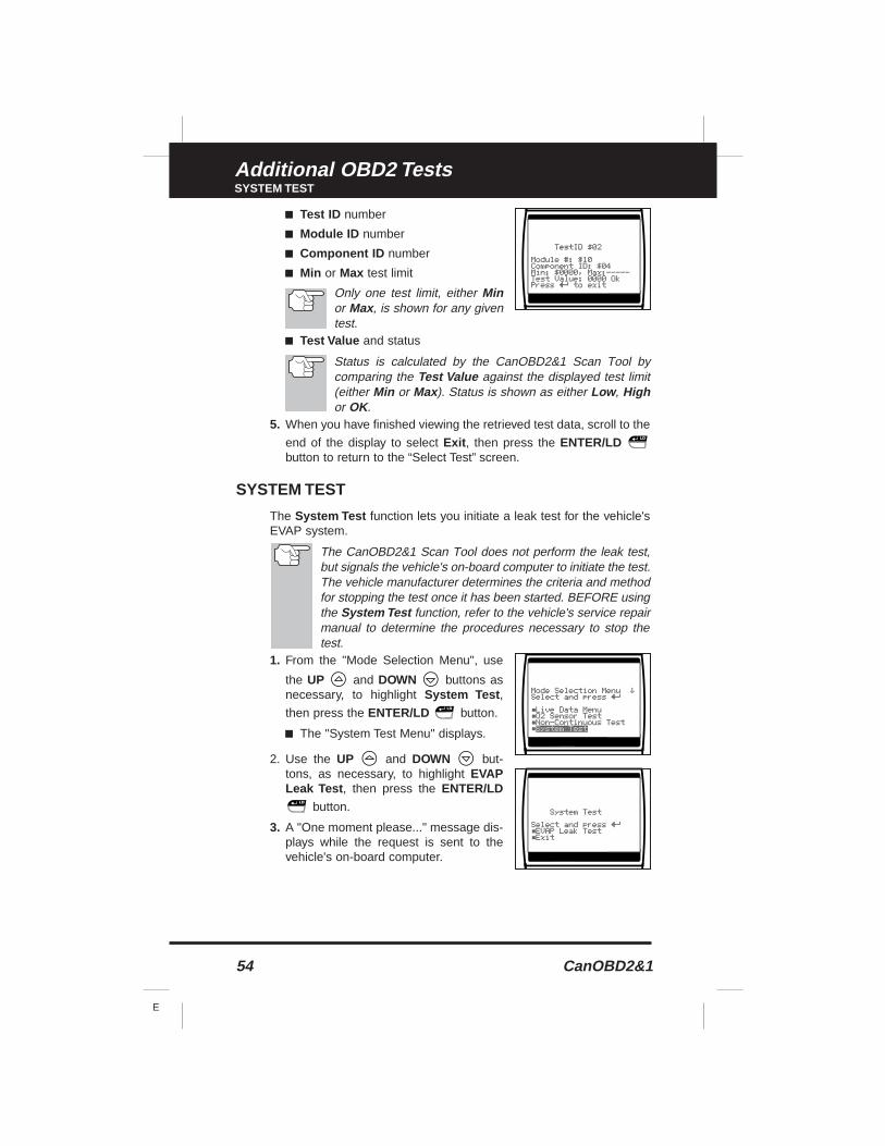
54 CanOBD2&1
E
Additional OBD2 TestsSYSTEM TEST
■ Test ID number
■ Module ID number
■ Component ID number
■ Min or Max test limit
Only one test limit, either Minor Max, is shown for any giventest.
■ Test Value and status
Status is calculated by the CanOBD2&1 Scan Tool bycomparing the Test Value against the displayed test limit(either Min or Max). Status is shown as either Low , Highor OK.
5. When you have finished viewing the retrieved test data, scroll to the
end of the display to select Exit , then press the ENTER/LDbutton to return to the “Select Test” screen.
SYSTEM TEST
The System Test function lets you initiate a leak test for the vehicle'sEVAP system.
The CanOBD2&1 Scan Tool does not perform the leak test,but signals the vehicle's on-board computer to initiate the test.The vehicle manufacturer determines the criteria and methodfor stopping the test once it has been started. BEFORE usingthe System Test function, refer to the vehicle's service repairmanual to determine the procedures necessary to stop thetest.
1. From the "Mode Selection Menu", use
the UP and DOWN buttons asnecessary, to highlight System Test ,
then press the ENTER/LD button.
■ The "System Test Menu" displays.
2. Use the UP and DOWN but-tons, as necessary, to highlight EVAPLeak Test , then press the ENTER/LD
button.
3. A "One moment please..." message dis-plays while the request is sent to thevehicle's on-board computer.
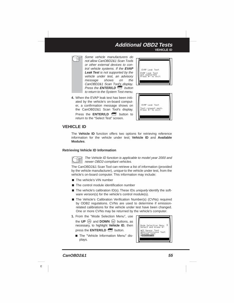
CanOBD2&1 55
E
Additional OBD2 TestsVEHICLE ID
Some vehicle manufacturers donot allow CanOBD2&1 Scan Toolsor other external devices to con-trol vehicle systems. If the EVAPLeak Test is not supported by thevehicle under test, an advisorymessage shows on theCanOBD2&1 Scan Tool's display.Press the ENTER/LD buttonto return to the System Test menu.
4. When the EVAP leak test has been initi-ated by the vehicle's on-board comput-er, a confirmation message shows onthe CanOBD2&1 Scan Tool's display.
Press the ENTER/LD button toreturn to the “Select Test” screen.
VEHICLE ID
The Vehicle ID function offers two options for retrieving referenceinformation for the vehicle under test; Vehicle ID and AvailableModules .
Retrieving Vehicle ID Information
The Vehicle ID function is applicable to model year 2000 andnewer OBD2-compliant vehicles.
The CanOBD2&1 Scan Tool can retrieve a list of information (providedby the vehicle manufacturer), unique to the vehicle under test, from thevehicle's on-board computer. This information may include:
■ The vehicle's VIN number
■ The control module identification number
■ The vehicle's calibration ID(s). These IDs uniquely identify the soft-ware version(s) for the vehicle's control module(s).
■ The Vehicle's Calibration Verification Number(s) (CVNs) requiredby ODB2 regulations. CVNs are used to determine if emission-related calibrations for the vehicle under test have been changed.One or more CVNs may be returned by the vehicle's computer.
1. From the "Mode Selection Menu", use
the UP and DOWN buttons, asnecessary, to highlight Vehicle ID , then
press the ENTER/LD button.
■ The "Vehicle Information Menu" dis-plays.
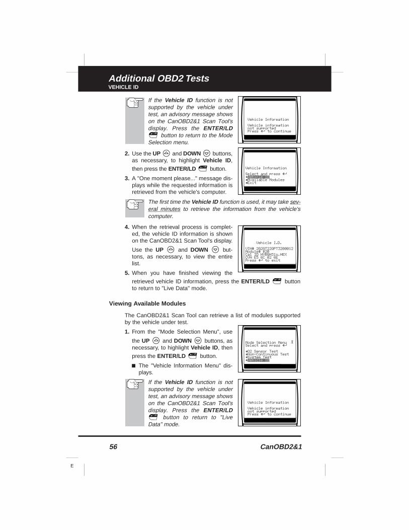
56 CanOBD2&1
E
Additional OBD2 TestsVEHICLE ID
If the Vehicle ID function is notsupported by the vehicle undertest, an advisory message showson the CanOBD2&1 Scan Tool'sdisplay. Press the ENTER/LD
button to return to the ModeSelection menu.
2. Use the UP and DOWN buttons,as necessary, to highlight Vehicle ID ,
then press the ENTER/LD button.
3. A "One moment please..." message dis-plays while the requested information isretrieved from the vehicle's computer.
The first time the Vehicle ID function is used, it may take sev-eral minutes to retrieve the information from the vehicle'scomputer.
4. When the retrieval process is complet-ed, the vehicle ID information is shownon the CanOBD2&1 Scan Tool's display.
Use the UP and DOWN but-tons, as necessary, to view the entirelist.
5. When you have finished viewing the
retrieved vehicle ID information, press the ENTER/LD buttonto return to "Live Data" mode.
Viewing Available Modules
The CanOBD2&1 Scan Tool can retrieve a list of modules supportedby the vehicle under test.
1. From the "Mode Selection Menu", use
the UP and DOWN buttons, asnecessary, to highlight Vehicle ID , then
press the ENTER/LD button.
■ The "Vehicle Information Menu" dis-plays.
If the Vehicle ID function is notsupported by the vehicle undertest, an advisory message showson the CanOBD2&1 Scan Tool'sdisplay. Press the ENTER/LD
button to return to "LiveData" mode.
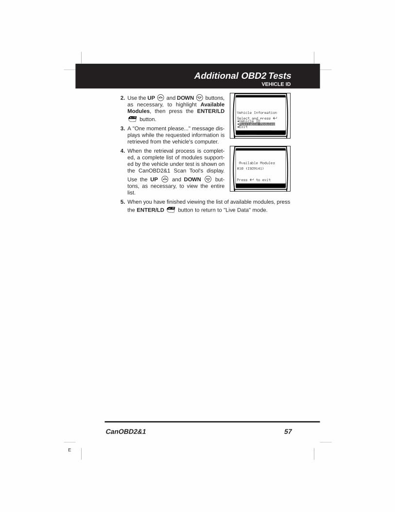
CanOBD2&1 57
E
Additional OBD2 TestsVEHICLE ID
2. Use the UP and DOWN buttons,as necessary, to highlight AvailableModules , then press the ENTER/LD
button.
3. A "One moment please..." message dis-plays while the requested information isretrieved from the vehicle's computer.
4. When the retrieval process is complet-ed, a complete list of modules support-ed by the vehicle under test is shown onthe CanOBD2&1 Scan Tool's display.
Use the UP and DOWN but-tons, as necessary, to view the entirelist.
5. When you have finished viewing the list of available modules, press
the ENTER/LD button to return to "Live Data" mode.
58 CanOBD2&1
E
Chrysler/Jeep OBD1 SystemsCHRYSLER/JEEP OBD1 SYSTEMS
CHRYSLER/JEEP OBD1 SYSTEMS
Chrysler Motors On-Board Computer Systems
Chrysler Motors introduced its first electronic fuel injected vehicle inlate 1983. The on-board computer management systems used onChrysler vehicles have evolved over the years, and their names havechanged accordingly.
1983-87: The on-board computer used in these vehicles is a split-system, composed of two separate units: the Logic Module and thePower Module. The Logic Module contains a microprocessor whichprocesses data received from sensors located throughout the vehicleand makes decisions (based on these inputs) which effect engineoperation. The Logic Module is usually located on the right-hand side,behind the kick panel. The Power Module supplies operating power tothe Logic Module, and contains the circuits which control the high-current devices. Power Module operation is controlled by the LogicModule.The Power Module is located in the engine compartment, nearthe vehicle’s battery.
1987-90: This system is called a Single Module Engine Controller(SMEC). This system still uses two separate circuit boards (LogicModule and Power Module). However, both circuit boards are locatedin a common enclosure.
1989-95: This system is called a Single Board Engine Controller(SBEC). On this system, the Logic Module and Power Module circuitboards are integrated on a single circuit board.
1993-97: Beginning in 1993, the computer was renamed thePowertrain Control Module (PCM). In addition to controlling the enginemanagement system and emission system, the computer also takes anactive role in controlling powertrain (transmission system) operation.
Unless otherwise specified, all references to “computer” withinthis manual also apply to “Logic Module/ Power Module”,“SMEC”, “SBEC” or “PCM”.
Jeep On-Board Computer Systems
1993-95: In 1993, Jeep on-board computer systems (fuel injectedvehicles only) were converted to the Chrysler on-board computer sys-tems. All 1993 through 1995 fuel injected Jeep and Chrysler vehiclesare equipped with similar on-board computer systems.
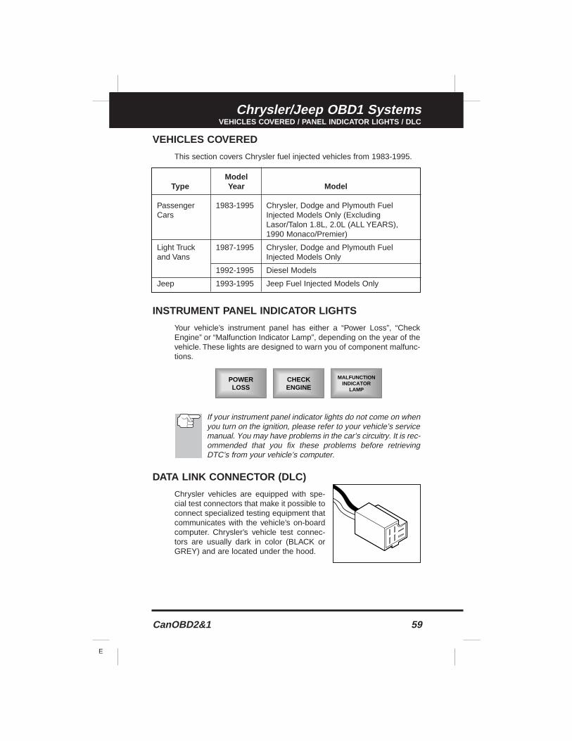
CanOBD2&1 59
E
Chrysler/Jeep OBD1 SystemsVEHICLES COVERED / PANEL INDICATOR LIGHTS / DLC
VEHICLES COVERED
This section covers Chrysler fuel injected vehicles from 1983-1995.
INSTRUMENT PANEL INDICATOR LIGHTS
Your vehicle’s instrument panel has either a “Power Loss”, “CheckEngine” or “Malfunction Indicator Lamp”, depending on the year of thevehicle. These lights are designed to warn you of component malfunc-tions.
If your instrument panel indicator lights do not come on whenyou turn on the ignition, please refer to your vehicle’s servicemanual. You may have problems in the car’s circuitry. It is rec-ommended that you fix these problems before retrievingDTC’s from your vehicle’s computer.
DATA LINK CONNECTOR (DLC)
Chrysler vehicles are equipped with spe-cial test connectors that make it possible toconnect specialized testing equipment thatcommunicates with the vehicle’s on-boardcomputer. Chrysler’s vehicle test connec-tors are usually dark in color (BLACK orGREY) and are located under the hood.
ModelType Year Model
Passenger 1983-1995 Chrysler, Dodge and Plymouth FuelCars Injected Models Only (Excluding
Lasor/Talon 1.8L, 2.0L (ALL YEARS), 1990 Monaco/Premier)
Light Truck 1987-1995 Chrysler, Dodge and Plymouth Fueland Vans Injected Models Only
1992-1995 Diesel Models
Jeep 1993-1995 Jeep Fuel Injected Models Only
POWERLOSS
CHECKENGINE
MALFUNCTIONINDICATOR
LAMP
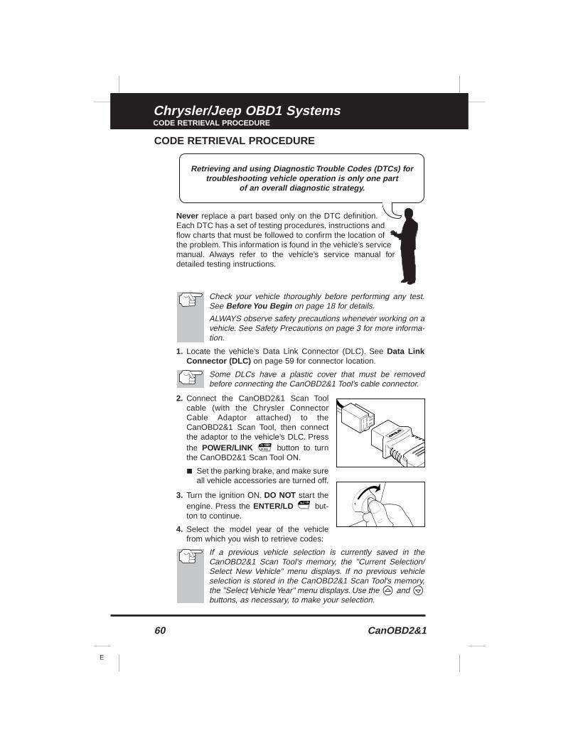
60 CanOBD2&1
E
Chrysler/Jeep OBD1 SystemsCODE RETRIEVAL PROCEDURE
CODE RETRIEVAL PROCEDURE
Never replace a part based only on the DTC definition.Each DTC has a set of testing procedures, instructions andflow charts that must be followed to confirm the location ofthe problem. This information is found in the vehicle’s servicemanual. Always refer to the vehicle’s service manual fordetailed testing instructions.
Check your vehicle thoroughly before performing any test.See Before You Begin on page 18 for details.
ALWAYS observe safety precautions whenever working on avehicle. See Safety Precautions on page 3 for more informa-tion.
1. Locate the vehicle’s Data Link Connector (DLC). See Data LinkConnector (DLC) on page 59 for connector location.
Some DLCs have a plastic cover that must be removedbefore connecting the CanOBD2&1 Tool’s cable connector.
2. Connect the CanOBD2&1 Scan Toolcable (with the Chrysler ConnectorCable Adaptor attached) to theCanOBD2&1 Scan Tool, then connectthe adaptor to the vehicle’s DLC. Pressthe POWER/LINK button to turnthe CanOBD2&1 Scan Tool ON.
■ Set the parking brake, and make sureall vehicle accessories are turned off.
3. Turn the ignition ON. DO NOT start theengine. Press the ENTER/LD but-ton to continue.
4. Select the model year of the vehiclefrom which you wish to retrieve codes:
If a previous vehicle selection is currently saved in theCanOBD2&1 Scan Tool's memory, the "Current Selection/Select New Vehicle" menu displays. If no previous vehicleselection is stored in the CanOBD2&1 Scan Tool's memory,the "Select Vehicle Year" menu displays. Use the andbuttons, as necessary, to make your selection.
Retrieving and using Diagnostic Trouble Codes (DTCs) fortroubleshooting vehicle operation is only one part
of an overall diagnostic strategy.
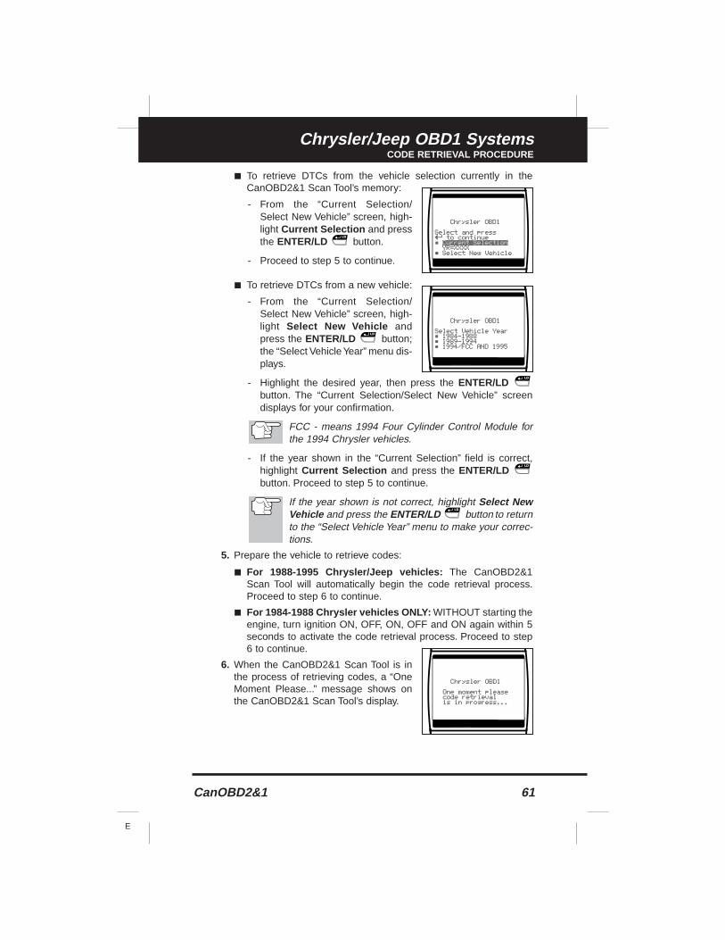
CanOBD2&1 61
E
Chrysler/Jeep OBD1 SystemsCODE RETRIEVAL PROCEDURE
■ To retrieve DTCs from the vehicle selection currently in theCanOBD2&1 Scan Tool’s memory:
- From the “Current Selection/Select New Vehicle” screen, high-light Current Selection and pressthe ENTER/LD button.
- Proceed to step 5 to continue.
■ To retrieve DTCs from a new vehicle:
- From the “Current Selection/Select New Vehicle” screen, high-light Select New Vehicle andpress the ENTER/LD button;the “Select Vehicle Year” menu dis-plays.
- Highlight the desired year, then press the ENTER/LDbutton. The “Current Selection/Select New Vehicle” screendisplays for your confirmation.
FCC - means 1994 Four Cylinder Control Module forthe 1994 Chrysler vehicles.
- If the year shown in the “Current Selection” field is correct,highlight Current Selection and press the ENTER/LDbutton. Proceed to step 5 to continue.
If the year shown is not correct, highlight Select NewVehicle and press the ENTER/LD button to returnto the “Select Vehicle Year” menu to make your correc-tions.
5. Prepare the vehicle to retrieve codes:
■ For 1988-1995 Chrysler/Jeep vehicles: The CanOBD2&1Scan Tool will automatically begin the code retrieval process.Proceed to step 6 to continue.
■ For 1984-1988 Chrysler vehicles ONLY: WITHOUT starting theengine, turn ignition ON, OFF, ON, OFF and ON again within 5seconds to activate the code retrieval process. Proceed to step6 to continue.
6. When the CanOBD2&1 Scan Tool is inthe process of retrieving codes, a “OneMoment Please...” message shows onthe CanOBD2&1 Scan Tool’s display.
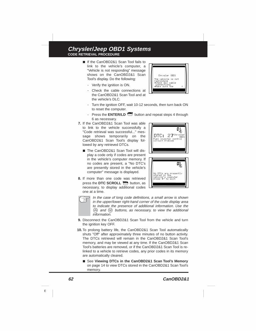
62 CanOBD2&1
E
Chrysler/Jeep OBD1 SystemsCODE RETRIEVAL PROCEDURE
■ If the CanOBD2&1 Scan Tool fails tolink to the vehicle’s computer, a“Vehicle is not responding” messageshows on the CanOBD2&1 ScanTool’s display. Do the following:
- Verify the ignition is ON.
- Check the cable connections atthe CanOBD2&1 Scan Tool and atthe vehicle’s DLC.
- Turn the ignition OFF, wait 10-12 seconds, then turn back ONto reset the computer.
- Press the ENTER/LD button and repeat steps 4 through6 as necessary.
7. If the CanOBD2&1 Scan Tool was ableto link to the vehicle successfully a"Code retrieval was successful..." mes-sage shows temporarily on theCanOBD2&1 Scan Tool’s display fol-lowed by any retrieved DTCs.
■ The CanOBD2&1 Scan Tool will dis-play a code only if codes are presentin the vehicle's computer memory. Ifno codes are present, a "No DTC'sare presently stored in the vehicle'scomputer" message is displayed.
8. If more than one code was retrievedpress the DTC SCROLL button, asnecessary, to display additional codesone at a time.
In the case of long code definitions, a small arrow is shownin the upper/lower right-hand corner of the code display areato indicate the presence of additional information. Use the
and buttons, as necessary, to view the additionalinformation.
9. Disconnect the CanOBD2&1 Scan Tool from the vehicle and turnthe ignition key OFF.
10. To prolong battery life, the CanOBD2&1 Scan Tool automaticallyshuts "Off" after approximately three minutes of no button activity.The DTCs retrieved will remain in the CanOBD2&1 Scan Tool'smemory, and may be viewed at any time. If the CanOBD2&1 ScanTool’s batteries are removed, or if the CanOBD2&1 Scan Tool is re-linked to a vehicle to retrieve codes, any prior codes in its memoryare automatically cleared.
■ See Viewing DTCs in the CanOBD2&1 Scan Tool’s Memoryon page 14 to view DTCs stored in the CanOBD2&1 Scan Tool’smemory.
CanOBD2&1 63
E
Chrysler/Jeep OBD1 SystemsCODE RETRIEVAL PROCEDURE
11. Follow the testing and repair procedures outlined in the vehicle'sservice repair manual to correct "hard" DTCs. Codes should beaddressed and eliminated in the order they were received, erasing(see Erasing DTC's on page 102) and retesting after each repair ismade to be sure the fault was eliminated.
The green, yellow and red LEDs are used (with the LCD dis-play) as visual aids to make it easier to determine engine sys-tem conditions. See Servicing Diagnostic Trouble Codeson page 100 for information on interpreting LEDs and servic-ing DTCs.
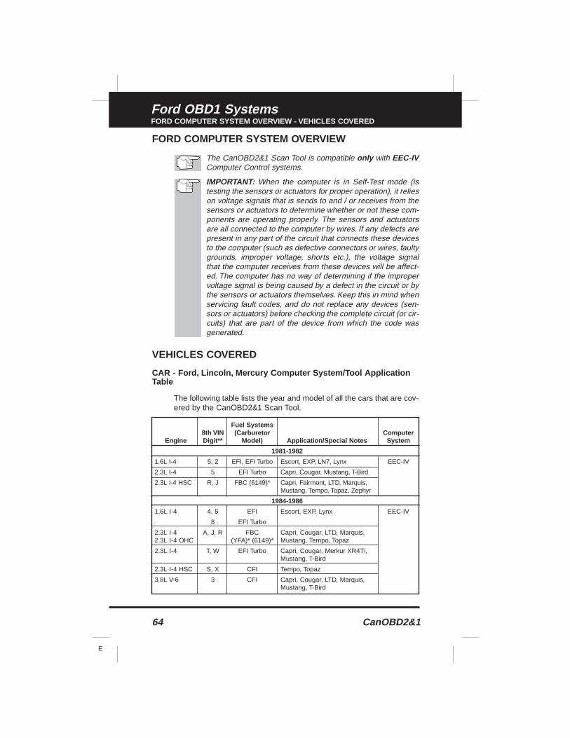
64 CanOBD2&1
E
Ford OBD1 SystemsFORD COMPUTER SYSTEM OVERVIEW - VEHICLES COVERED
FORD COMPUTER SYSTEM OVERVIEW
The CanOBD2&1 Scan Tool is compatible only with EEC-IVComputer Control systems.
IMPORTANT: When the computer is in Self-Test mode (istesting the sensors or actuators for proper operation), it relieson voltage signals that is sends to and / or receives from thesensors or actuators to determine whether or not these com-ponents are operating properly. The sensors and actuatorsare all connected to the computer by wires. If any defects arepresent in any part of the circuit that connects these devicesto the computer (such as defective connectors or wires, faultygrounds, improper voltage, shorts etc.), the voltage signalthat the computer receives from these devices will be affect-ed. The computer has no way of determining if the impropervoltage signal is being caused by a defect in the circuit or bythe sensors or actuators themselves. Keep this in mind whenservicing fault codes, and do not replace any devices (sen-sors or actuators) before checking the complete circuit (or cir-cuits) that are part of the device from which the code wasgenerated.
VEHICLES COVERED
CAR - Ford, Lincoln, Mercury Computer System/Tool ApplicationTable
The following table lists the year and model of all the cars that are cov-ered by the CanOBD2&1 Scan Tool.
Fuel Systems8th VIN (Carburetor Computer
Engine Digit** Model) Application/Special Notes System
1981-1982
1.6L I-4 5, 2 EFI, EFI Turbo Escort, EXP, LN7, Lynx EEC-IV
2.3L I-4 5 EFI Turbo Capri, Cougar, Mustang, T-Bird
2.3L I-4 HSC R, J FBC (6149)* Capri, Fairmont, LTD, Marquis,Mustang, Tempo, Topaz, Zephyr
1984-1986
1.6L I-4 4, 5 EFI Escort, EXP, Lynx EEC-IV
8 EFI Turbo
2.3L I-4 A, J, R FBC Capri, Cougar, LTD, Marquis, 2.3L I-4 OHC (YFA)* (6149)* Mustang, Tempo, Topaz
2.3L I-4 T, W EFI Turbo Capri, Cougar, Merkur XR4Ti,Mustang, T-Bird
2.3L I-4 HSC S, X CFI Tempo, Topaz
3.8L V-6 3 CFI Capri, Cougar, LTD, Marquis,Mustang, T-Bird
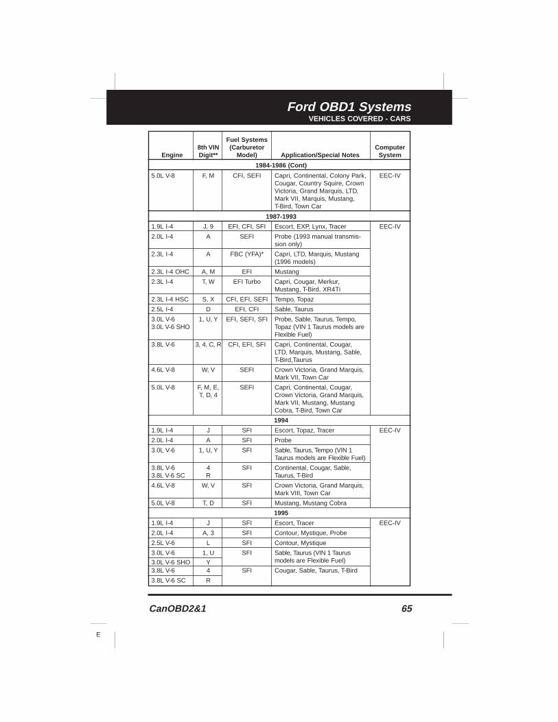
CanOBD2&1 65
E
Ford OBD1 SystemsVEHICLES COVERED - CARS
Fuel Systems8th VIN (Carburetor Computer
Engine Digit** Model) Application/Special Notes System
1984-1986 (Cont)
5.0L V-8 F, M CFI, SEFI Capri, Continental, Colony Park, EEC-IVCougar, Country Squire, CrownVictoria, Grand Marquis, LTD,Mark VII, Marquis, Mustang,T-Bird, Town Car
1987-1993
1.9L I-4 J, 9 EFI, CFI, SFI Escort, EXP, Lynx, Tracer EEC-IV
2.0L I-4 A SEFI Probe (1993 manual transmis-sion only)
2.3L I-4 A FBC (YFA)* Capri, LTD, Marquis, Mustang(1996 models)
2.3L I-4 OHC A, M EFI Mustang
2.3L I-4 T, W EFI Turbo Capri, Cougar, Merkur, Mustang, T-Bird, XR4Ti
2.3L I-4 HSC S, X CFI, EFI, SEFI Tempo, Topaz
2.5L I-4 D EFI, CFI Sable, Taurus
3.0L V-6 1, U, Y EFI, SEFI, SFI Probe, Sable, Taurus, Tempo, 3.0L V-6 SHO Topaz (VIN 1 Taurus models are
Flexible Fuel)
3.8L V-6 3, 4, C, R CFI, EFI, SFI Capri, Continental, Cougar, LTD, Marquis, Mustang, Sable, T-Bird,Taurus
4.6L V-8 W, V SEFI Crown Victoria, Grand Marquis,Mark VII, Town Car
5.0L V-8 F, M, E, SEFI Capri, Continental, Cougar, T, D, 4 Crown Victoria, Grand Marquis,
Mark VII, Mustang, Mustang Cobra, T-Bird, Town Car
1994
1.9L I-4 J SFI Escort, Topaz, Tracer EEC-IV
2.0L I-4 A SFI Probe
3.0L V-6 1, U, Y SFI Sable, Taurus, Tempo (VIN 1 Taurus models are Flexible Fuel)
3.8L V-6 4 SFI Continental, Cougar, Sable, 3.8L V-6 SC R Taurus, T-Bird
4.6L V-8 W, V SFI Crown Victoria, Grand Marquis,Mark VIII, Town Car
5.0L V-8 T, D SFI Mustang, Mustang Cobra
1995
1.9L I-4 J SFI Escort, Tracer EEC-IV
2.0L I-4 A, 3 SFI Contour, Mystique, Probe
2.5L V-6 L SFI Contour, Mystique
3.0L V-6 1, U SFI Sable, Taurus (VIN 1 Taurus
3.0L V-6 SHO Y models are Flexible Fuel)
3.8L V-6 4 SFI Cougar, Sable, Taurus, T-Bird
3.8L V-6 SC R
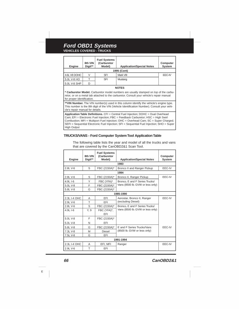
66 CanOBD2&1
E
Ford OBD1 SystemsVEHICLES COVERED - TRUCKS
TRUCKS/VANS - Ford Computer System Tool Application Table
The following table lists the year and model of all the trucks and vansthat are covered by the CanOBD2&1 Scan Tool.
Fuel Systems8th VIN (Carburetor Computer
Engine Digit** Model) Application/Special Notes System
1995 (Cont)
4.6L V8 DOHC V SFI Mark VIII EEC-IV
5.0L V-8 HO T SFI Mustang
5.0L V-8 SHP D
NOTES
* Carburetor Model. Carburetor model numbers are usually stamped on top of the carbu-retor, or on a metal tab attached to the carburetor. Consult your vehicle’s repair manualfor proper identification.
**VIN Number. The VIN number(s) used in this column identify the vehicle’s engine type.This number is the 8th digit of the VIN (Vehicle Identification Number). Consult your vehi-cle’s repair manual for details.
Application Table Definitions. CFI = Central Fuel Injection; DOHC = Dual OverheadCam; EFI = Electronic Fuel Injection; FBC = Feedback Carburetor; HSC = High SwirlCombustion; MFI = Multiport Fuel Injection; OHC = Overhead Cam; SC = Super Charged;SEFI = Sequential Electronic Fuel Injection; SFI = Sequential Fuel Injection; SHO = SuperHigh Output
Fuel Systems8th VIN (Carburetor Computer
Engine Digit** Model) Application/Special Notes System
1983
2.8L V-6 S FBC (2150A)* Bronco II and Ranger Pickup EEC-IV
1984
2.8L V-6 S FBC (2150A)* Bronco II, Ranger Pickup EEC-IV
4.9L I-6 Y FBC (YFA)* Bronco, E and F Series Trucks/
5.0L V-8 F FBC (2150A)* Vans (8500 lb. GVW or less only)
5.8L V-8 G FBC (2150A)*
1985-1990
2.3L I-4 OHC A EFI Aerostar, Bronco II, Ranger EEC-IV
2.9L V-6 T EFI (excluding Diesel)
2.8L V-6 S FBC (2150A)* Bronco, E and F Series Trucks/
4.9L I-6 Y, 9 FBC (YFA)*, Vans (8500 lb. GVW or less only)
EFI
5.0L V-8 F FBC (2150A)*
5.0L V-8 N EFI
5.8L V-8 G FBC (2150A)* E and F Series Trucks/Vans EEC-IV
7.3L V-8 M Diesel (8500 lb. GVW or less only)
7.5L V-8 G EFI
1991-1994
2.3L I-4 OHC A EFI, MFI Ranger EEC-IV
2.9L V-6 T EFI
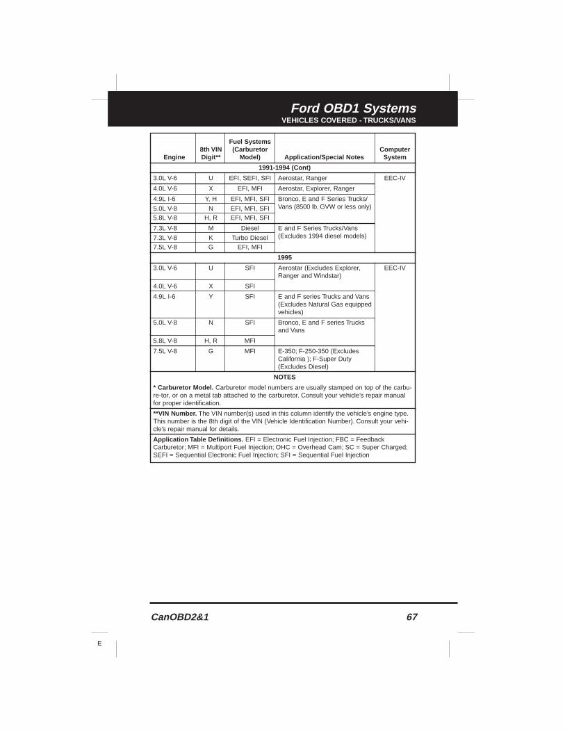
CanOBD2&1 67
E
Ford OBD1 SystemsVEHICLES COVERED - TRUCKS/VANS
Fuel Systems8th VIN (Carburetor Computer
Engine Digit** Model) Application/Special Notes System
1991-1994 (Cont)
3.0L V-6 U EFI, SEFI, SFI Aerostar, Ranger EEC-IV
4.0L V-6 X EFI, MFI Aerostar, Explorer, Ranger
4.9L I-6 Y, H EFI, MFI, SFI Bronco, E and F Series Trucks/
5.0L V-8 N EFI, MFI, SFI Vans (8500 lb. GVW or less only)
5.8L V-8 H, R EFI, MFI, SFI
7.3L V-8 M Diesel E and F Series Trucks/Vans
7.3L V-8 K Turbo Diesel (Excludes 1994 diesel models)
7.5L V-8 G EFI, MFI
1995
3.0L V-6 U SFI Aerostar (Excludes Explorer, EEC-IVRanger and Windstar)
4.0L V-6 X SFI
4.9L I-6 Y SFI E and F series Trucks and Vans (Excludes Natural Gas equippedvehicles)
5.0L V-8 N SFI Bronco, E and F series Trucks and Vans
5.8L V-8 H, R MFI
7.5L V-8 G MFI E-350; F-250-350 (Excludes California ); F-Super Duty(Excludes Diesel)
NOTES
* Carburetor Model. Carburetor model numbers are usually stamped on top of the carbu-re-tor, or on a metal tab attached to the carburetor. Consult your vehicle’s repair manualfor proper identification.
**VIN Number. The VIN number(s) used in this column identify the vehicle’s engine type.This number is the 8th digit of the VIN (Vehicle Identification Number). Consult your vehi-cle’s repair manual for details.
Application Table Definitions. EFI = Electronic Fuel Injection; FBC = FeedbackCarburetor; MFI = Multiport Fuel Injection; OHC = Overhead Cam; SC = Super Charged;SEFI = Sequential Electronic Fuel Injection; SFI = Sequential Fuel Injection
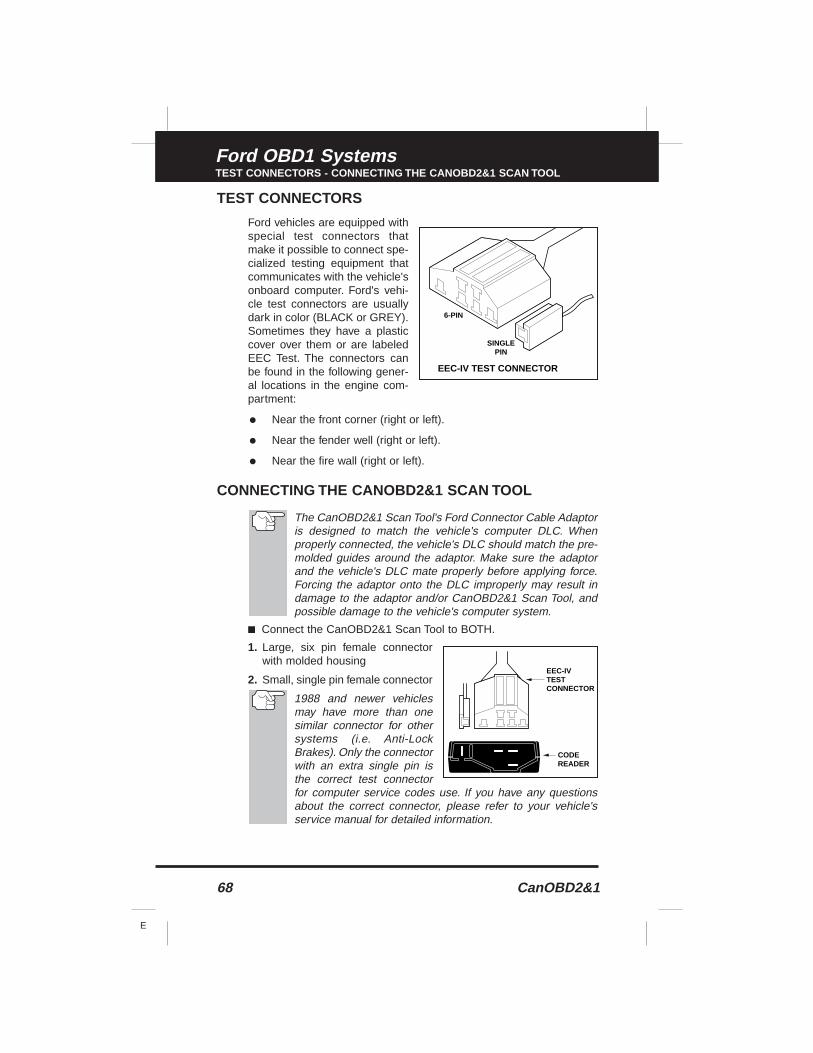
68 CanOBD2&1
E
Ford OBD1 SystemsTEST CONNECTORS - CONNECTING THE CANOBD2&1 SCAN TOOL
TEST CONNECTORS
Ford vehicles are equipped withspecial test connectors thatmake it possible to connect spe-cialized testing equipment thatcommunicates with the vehicle'sonboard computer. Ford's vehi-cle test connectors are usuallydark in color (BLACK or GREY).Sometimes they have a plasticcover over them or are labeledEEC Test. The connectors canbe found in the following gener-al locations in the engine com-partment:
• Near the front corner (right or left).
• Near the fender well (right or left).
• Near the fire wall (right or left).
CONNECTING THE CANOBD2&1 SCAN TOOL
The CanOBD2&1 Scan Tool's Ford Connector Cable Adaptoris designed to match the vehicle's computer DLC. Whenproperly connected, the vehicle's DLC should match the pre-molded guides around the adaptor. Make sure the adaptorand the vehicle's DLC mate properly before applying force.Forcing the adaptor onto the DLC improperly may result indamage to the adaptor and/or CanOBD2&1 Scan Tool, andpossible damage to the vehicle's computer system.
■ Connect the CanOBD2&1 Scan Tool to BOTH.
1. Large, six pin female connectorwith molded housing
2. Small, single pin female connector
1988 and newer vehiclesmay have more than onesimilar connector for othersystems (i.e. Anti-LockBrakes). Only the connectorwith an extra single pin isthe correct test connectorfor computer service codes use. If you have any questionsabout the correct connector, please refer to your vehicle'sservice manual for detailed information.
EEC-IV TEST CONNECTOR
6-PIN
SINGLEPIN
CODEREADER
EEC-IVTESTCONNECTOR
CanOBD2&1 69
E
Ford OBD1 SystemsDIAGNOSTIC TROUBLE CODES / CODE RETRIEVAL PROCEDURES - OVERVIEW
DIAGNOSTIC TROUBLE CODES (DTCs)
Diagnostic Trouble Codes, or Fault Codes, can be used to identifyengine systems or components that are malfunctioning. The computerrecords codes for two types of problems:
■ "Hard" Diagnostic Trouble Codes
"Hard" DTCs represent problems which are happening now andcause the instrument panel Malfunction Indicator Lamp (MIL) orCheck engine light to illuminate and remain on until the failure isrepaired. A DTC is stored in the vehicle's computer memory foreach fault detected. A Tool or Scanner can be used to retrieveDTCs that are stored in the vehicle's computer memory.
■ Intermittent/History DTCs
Intermittent/History DTCs are stored in the computer's memory forproblems that occur intermittently, or for problems that happened inthe past but are not currently present. Intermittent DTCs may causethe Malfunction Indicator light to flicker or stay on until the intermit-tent malfunction goes away. However, the corresponding fault codewill be stored in memory as a history DTC. If the malfunction thatcaused the history DTC to set does not recur within a predeter-mined length of time (usually within 40-80 ignition key start cycles),the computer will automatically erase the related fault code from itsmemory.
CODE RETRIEVAL PROCEDURES
Overview of Ford Code Retrieval Process
Ford's computer self-diagnostic system is divided into four main sec-tions:
1. "Key On Engine Off" (KOEO) Self-Test
2. "Continuous Memory" (CM) Self-Test
3. "Key On Engine Running" (KOER) Self-Test
4. Other EEC-IV System tests
These Self-Tests are specially designed to monitor and/or test the var-ious components and circuits that are controlled by the vehicle's com-puter, and to save and/or transmit diagnostic test results to theCanOBD2&1 Scan Tool in the form of numerical fault codes.
The "Continuous Memory" Self-Test is designed to run continuouslywhenever the vehicle is normal operation. If a fault is detected by the"Continuous Memory" Self-Test, a fault code is saved in the vehicle'scomputer memory for later retrieval.
Ford’s On-Board Diagnostic Self-Tests are designed in such a way thatin order to properly diagnose a problem, you must perform all the Self-Tests, in the proper sequence.
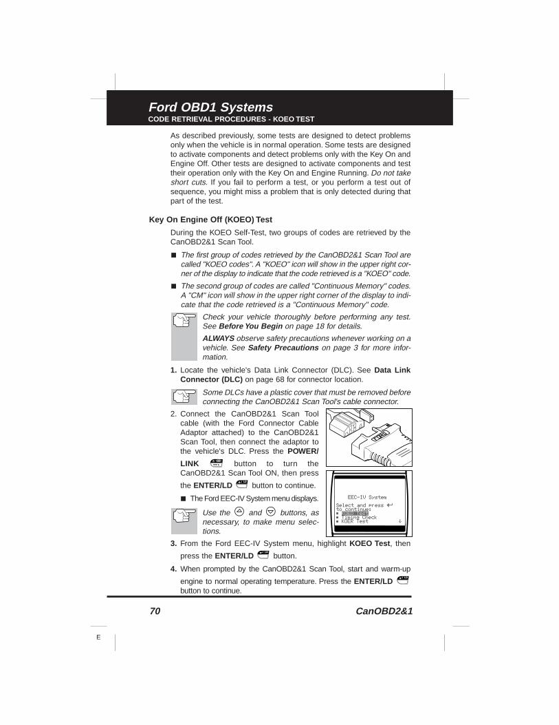
70 CanOBD2&1
E
Ford OBD1 SystemsCODE RETRIEVAL PROCEDURES - KOEO TEST
As described previously, some tests are designed to detect problemsonly when the vehicle is in normal operation. Some tests are designedto activate components and detect problems only with the Key On andEngine Off. Other tests are designed to activate components and testtheir operation only with the Key On and Engine Running. Do not takeshort cuts. If you fail to perform a test, or you perform a test out ofsequence, you might miss a problem that is only detected during thatpart of the test.
Key On Engine Off (KOEO) Test
During the KOEO Self-Test, two groups of codes are retrieved by theCanOBD2&1 Scan Tool.
■ The first group of codes retrieved by the CanOBD2&1 Scan Tool arecalled "KOEO codes". A "KOEO" icon will show in the upper right cor-ner of the display to indicate that the code retrieved is a "KOEO" code.
■ The second group of codes are called "Continuous Memory" codes.A "CM" icon will show in the upper right corner of the display to indi-cate that the code retrieved is a "Continuous Memory" code.
Check your vehicle thoroughly before performing any test.See Before You Begin on page 18 for details.
ALWAYS observe safety precautions whenever working on avehicle. See Safety Precautions on page 3 for more infor-mation.
1. Locate the vehicle's Data Link Connector (DLC). See Data LinkConnector (DLC) on page 68 for connector location.
Some DLCs have a plastic cover that must be removed beforeconnecting the CanOBD2&1 Scan Tool's cable connector.
2. Connect the CanOBD2&1 Scan Toolcable (with the Ford Connector CableAdaptor attached) to the CanOBD2&1Scan Tool, then connect the adaptor tothe vehicle's DLC. Press the POWER/
LINK button to turn theCanOBD2&1 Scan Tool ON, then press
the ENTER/LD button to continue.
■ The Ford EEC-IV System menu displays.
Use the and buttons, asnecessary, to make menu selec-tions.
3. From the Ford EEC-IV System menu, highlight KOEO Test , then
press the ENTER/LD button.
4. When prompted by the CanOBD2&1 Scan Tool, start and warm-up
engine to normal operating temperature. Press the ENTER/LDbutton to continue.
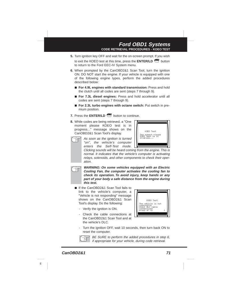
CanOBD2&1 71
E
Ford OBD1 SystemsCODE RETRIEVAL PROCEDURES - KOEO TEST
5. Turn ignition key OFF and wait for the on-screen prompt. If you wish
to exit the KOEO test at this time, press the ENTER/LD buttonto return to the Ford EEC-IV System menu.
6. When prompted by the CanOBD2&1 Scan Tool, turn the ignitionON. DO NOT start the engine. If your vehicle is equipped with oneof the following engine types, perform the added proceduresdescribed below:
■ For 4.9L engines with standard transmission: Press and holdthe clutch until all codes are sent (steps 7 through 9).
■ For 7.3L diesel engines: Press and hold accelerator until allcodes are sent (steps 7 through 9).
■ For 2.3L turbo engines with octane switch: Put switch in pre-mium position.
7. Press the ENTER/LD button to continue.
8. While codes are being retrieved, a "Onemoment please KOEO test is inprogress..." message shows on theCanOBD2&1 Scan Tool's display.
As soon as the ignition is turned"on", the vehicle's computerenters the Self-Test mode.Clicking sounds will be heard coming from the engine. This isnormal. It indicates that the vehicle's computer is activatingrelays, solenoids, and other components to check their oper-ation.
WARNING: On some vehicles equipped with an ElectricCooling Fan, the computer activates the cooling fan tocheck its operation. To avoid injury, keep hands or anypart of your body a safe distance from the engine duringthis test.
■ If the CanOBD2&1 Scan Tool fails tolink to the vehicle's computer, a"Vehicle is not responding" messageshows on the CanOBD2&1 ScanTool's display. Do the following:
- Verify the ignition is ON.
- Check the cable connections atthe CanOBD2&1 Scan Tool and atthe vehicle's DLC.
- Turn the ignition OFF, wait 10 seconds, then turn back ON toreset the computer.
BE SURE to perform the added procedures in step 6,if appropriate for your vehicle, during code retrieval.
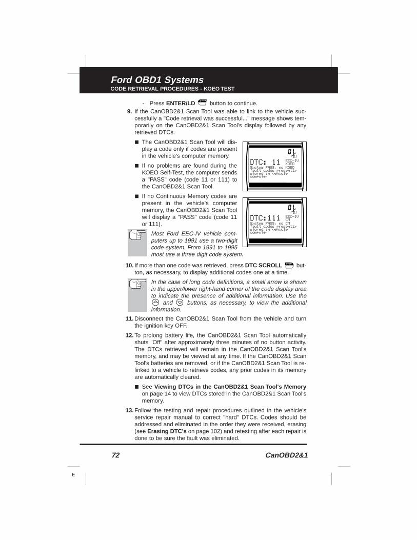
72 CanOBD2&1
E
Ford OBD1 SystemsCODE RETRIEVAL PROCEDURES - KOEO TEST
- Press ENTER/LD button to continue.9. If the CanOBD2&1 Scan Tool was able to link to the vehicle suc-
cessfully a "Code retrieval was successful..." message shows tem-porarily on the CanOBD2&1 Scan Tool's display followed by anyretrieved DTCs.
■ The CanOBD2&1 Scan Tool will dis-play a code only if codes are presentin the vehicle's computer memory.
■ If no problems are found during theKOEO Self-Test, the computer sendsa "PASS" code (code 11 or 111) tothe CanOBD2&1 Scan Tool.
■ If no Continuous Memory codes arepresent in the vehicle's computermemory, the CanOBD2&1 Scan Toolwill display a "PASS" code (code 11or 111).
Most Ford EEC-IV vehicle com-puters up to 1991 use a two-digitcode system. From 1991 to 1995most use a three digit code system.
10. If more than one code was retrieved, press DTC SCROLL but-ton, as necessary, to display additional codes one at a time.
In the case of long code definitions, a small arrow is shownin the upper/lower right-hand corner of the code display areato indicate the presence of additional information. Use the
and buttons, as necessary, to view the additionalinformation.
11. Disconnect the CanOBD2&1 Scan Tool from the vehicle and turnthe ignition key OFF.
12. To prolong battery life, the CanOBD2&1 Scan Tool automaticallyshuts "Off" after approximately three minutes of no button activity.The DTCs retrieved will remain in the CanOBD2&1 Scan Tool'smemory, and may be viewed at any time. If the CanOBD2&1 ScanTool's batteries are removed, or if the CanOBD2&1 Scan Tool is re-linked to a vehicle to retrieve codes, any prior codes in its memoryare automatically cleared.
■ See Viewing DTCs in the CanOBD2&1 Scan Tool's Memoryon page 14 to view DTCs stored in the CanOBD2&1 Scan Tool'smemory.
13. Follow the testing and repair procedures outlined in the vehicle'sservice repair manual to correct "hard" DTCs. Codes should beaddressed and eliminated in the order they were received, erasing(see Erasing DTC's on page 102) and retesting after each repair isdone to be sure the fault was eliminated.
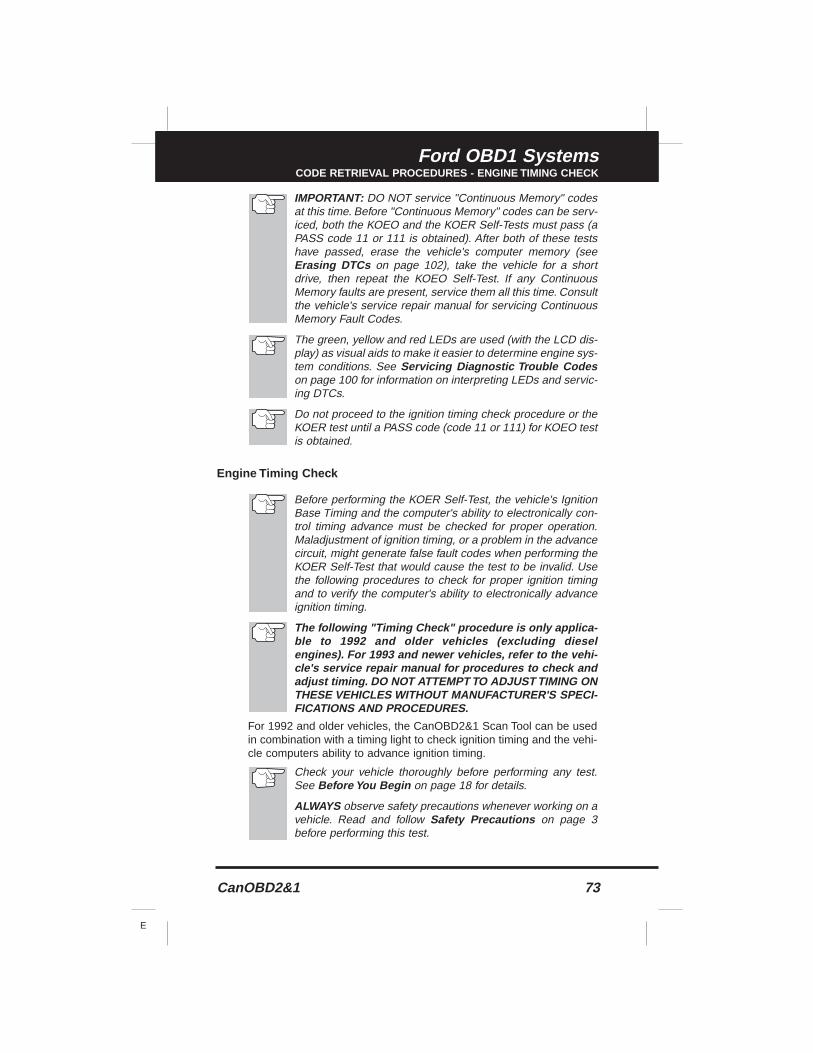
CanOBD2&1 73
E
Ford OBD1 SystemsCODE RETRIEVAL PROCEDURES - ENGINE TIMING CHECK
IMPORTANT: DO NOT service "Continuous Memory" codesat this time. Before "Continuous Memory" codes can be serv-iced, both the KOEO and the KOER Self-Tests must pass (aPASS code 11 or 111 is obtained). After both of these testshave passed, erase the vehicle's computer memory (seeErasing DTCs on page 102), take the vehicle for a shortdrive, then repeat the KOEO Self-Test. If any ContinuousMemory faults are present, service them all this time. Consultthe vehicle's service repair manual for servicing ContinuousMemory Fault Codes.
The green, yellow and red LEDs are used (with the LCD dis-play) as visual aids to make it easier to determine engine sys-tem conditions. See Servicing Diagnostic Trouble Codeson page 100 for information on interpreting LEDs and servic-ing DTCs.
Do not proceed to the ignition timing check procedure or theKOER test until a PASS code (code 11 or 111) for KOEO testis obtained.
Engine Timing Check
Before performing the KOER Self-Test, the vehicle's IgnitionBase Timing and the computer's ability to electronically con-trol timing advance must be checked for proper operation.Maladjustment of ignition timing, or a problem in the advancecircuit, might generate false fault codes when performing theKOER Self-Test that would cause the test to be invalid. Usethe following procedures to check for proper ignition timingand to verify the computer's ability to electronically advanceignition timing.
The following "Timing Check" procedure is only applica-ble to 1992 and older vehicles (excluding dieselengines). For 1993 and newer vehicles, refer to the vehi-cle's service repair manual for procedures to check andadjust timing. DO NOT ATTEMPT TO ADJUST TIMING ONTHESE VEHICLES WITHOUT MANUFACTURER'S SPECI-FICATIONS AND PROCEDURES.
For 1992 and older vehicles, the CanOBD2&1 Scan Tool can be usedin combination with a timing light to check ignition timing and the vehi-cle computers ability to advance ignition timing.
Check your vehicle thoroughly before performing any test.See Before You Begin on page 18 for details.
ALWAYS observe safety precautions whenever working on avehicle. Read and follow Safety Precautions on page 3before performing this test.
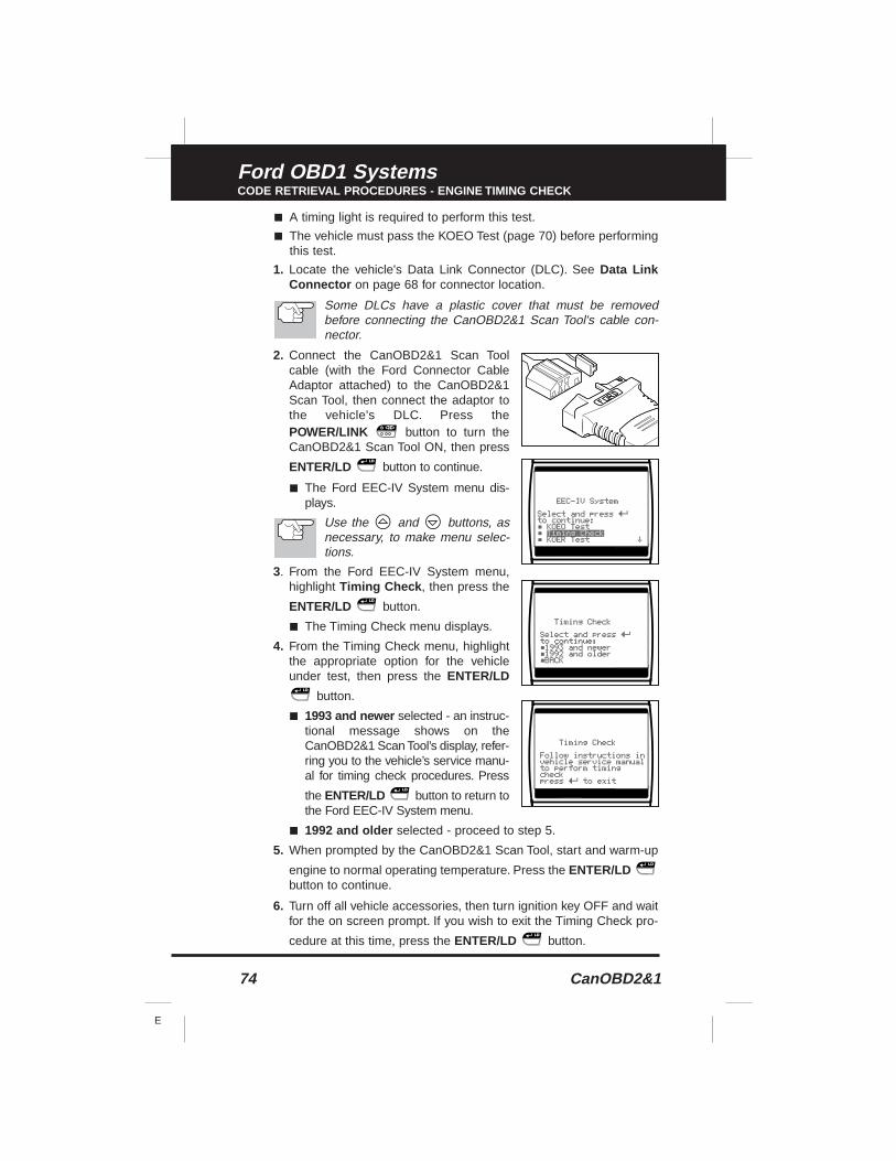
74 CanOBD2&1
E
Ford OBD1 SystemsCODE RETRIEVAL PROCEDURES - ENGINE TIMING CHECK
■ A timing light is required to perform this test.
■ The vehicle must pass the KOEO Test (page 70) before performingthis test.
1. Locate the vehicle's Data Link Connector (DLC). See Data LinkConnector on page 68 for connector location.
Some DLCs have a plastic cover that must be removedbefore connecting the CanOBD2&1 Scan Tool's cable con-nector.
2. Connect the CanOBD2&1 Scan Toolcable (with the Ford Connector CableAdaptor attached) to the CanOBD2&1Scan Tool, then connect the adaptor tothe vehicle's DLC. Press thePOWER/LINK button to turn theCanOBD2&1 Scan Tool ON, then press
ENTER/LD button to continue.
■ The Ford EEC-IV System menu dis-plays.
Use the and buttons, asnecessary, to make menu selec-tions.
3. From the Ford EEC-IV System menu,highlight Timing Check , then press the
ENTER/LD button.
■ The Timing Check menu displays.
4. From the Timing Check menu, highlightthe appropriate option for the vehicleunder test, then press the ENTER/LD
button.
■ 1993 and newer selected - an instruc-tional message shows on theCanOBD2&1 Scan Tool’s display, refer-ring you to the vehicle’s service manu-al for timing check procedures. Press
the ENTER/LD button to return tothe Ford EEC-IV System menu.
■ 1992 and older selected - proceed to step 5.
5. When prompted by the CanOBD2&1 Scan Tool, start and warm-up
engine to normal operating temperature. Press the ENTER/LDbutton to continue.
6. Turn off all vehicle accessories, then turn ignition key OFF and waitfor the on screen prompt. If you wish to exit the Timing Check pro-
cedure at this time, press the ENTER/LD button.
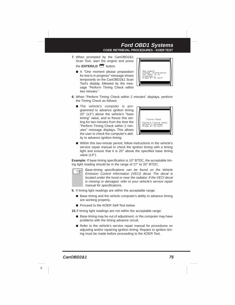
CanOBD2&1 75
E
Ford OBD1 SystemsCODE RETRIEVAL PROCEDURES - KOER TEST
7. When prompted by the CanOBD2&1Scan Tool, start the engine and press
the ENTER/LD button.
■ A "One moment please preparationfor test is in progress” message showstemporarily on the CanOBD2&1 ScanTool's display, followed by the mes-sage "Perform Timing Check withintwo minutes."
8. When "Perform Timing Check within 2 minutes" displays, performthe Timing Check as follows:
■ The vehicle's computer is pro-grammed to advance ignition timing20° (±3°) above the vehicle's "basetiming" value, and to freeze this set-ting for two minutes from the time the"Perform Timing Check within 2 min-utes" message displays. This allowsthe user to check the computer's abil-ity to advance ignition timing.
■ Within this two-minute period, follow instructions in the vehicle'sservice repair manual to check the ignition timing with a timinglight and ensure that it is 20° above the specified base timingvalue (±3°).
Example: If base timing specification is 10° BTDC, the acceptable tim-ing light reading should be in the range of 27° to 33° BTDC.
Base-timing specifications can be found on the VehicleEmission Control Information (VECI) decal. The decal islocated under the hood or near the radiator. If the VECI decalis missing or damaged, refer to your vehicle's service repairmanual for specifications.
9. If timing light readings are within the acceptable range:
■ Base timing and the vehicle computer's ability to advance timingare working properly.
■ Proceed to the KOER Self-Test below.
10. If timing light readings are not within the acceptable range:
■ Base timing may be out of adjustment, or the computer may haveproblems with the timing advance circuit.
■ Refer to the vehicle's service repair manual for procedures onadjusting and/or repairing ignition timing. Repairs to ignition tim-ing must be made before proceeding to the KOER Test.
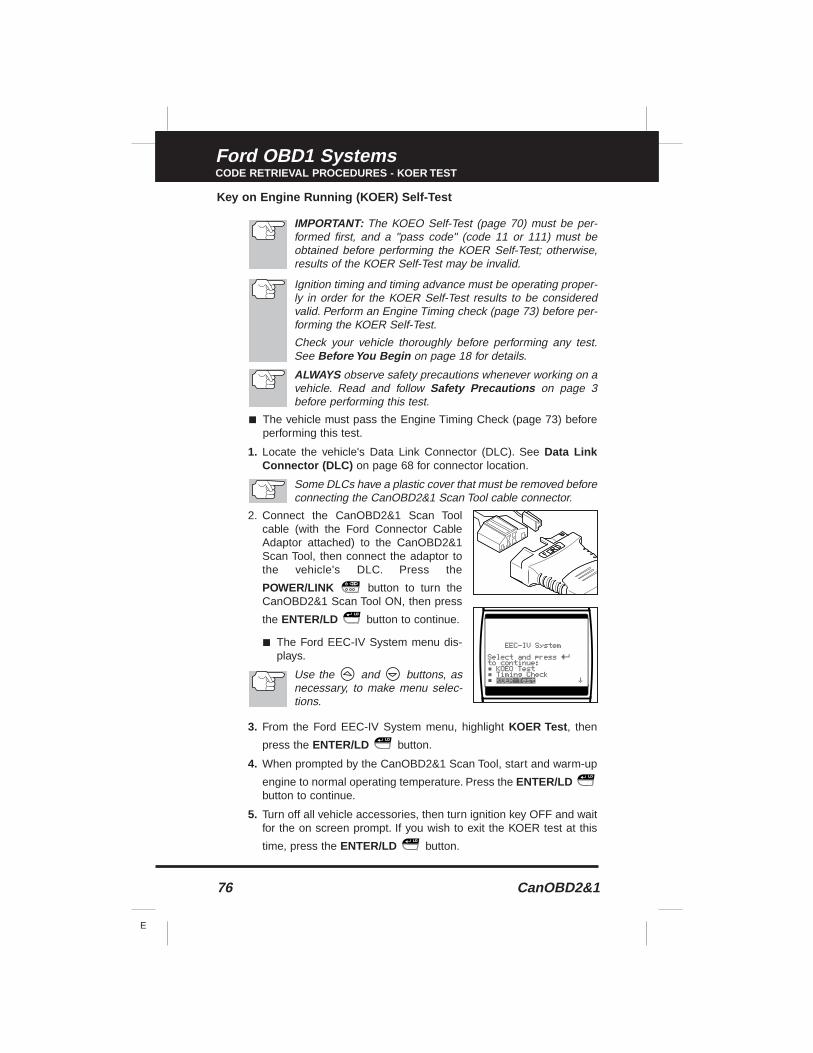
76 CanOBD2&1
E
Ford OBD1 SystemsCODE RETRIEVAL PROCEDURES - KOER TEST
Key on Engine Running (KOER) Self-Test
IMPORTANT: The KOEO Self-Test (page 70) must be per-formed first, and a "pass code" (code 11 or 111) must beobtained before performing the KOER Self-Test; otherwise,results of the KOER Self-Test may be invalid.
Ignition timing and timing advance must be operating proper-ly in order for the KOER Self-Test results to be consideredvalid. Perform an Engine Timing check (page 73) before per-forming the KOER Self-Test.
Check your vehicle thoroughly before performing any test.See Before You Begin on page 18 for details.
ALWAYS observe safety precautions whenever working on avehicle. Read and follow Safety Precautions on page 3before performing this test.
■ The vehicle must pass the Engine Timing Check (page 73) beforeperforming this test.
1. Locate the vehicle's Data Link Connector (DLC). See Data LinkConnector (DLC) on page 68 for connector location.
Some DLCs have a plastic cover that must be removed beforeconnecting the CanOBD2&1 Scan Tool cable connector.
2. Connect the CanOBD2&1 Scan Toolcable (with the Ford Connector CableAdaptor attached) to the CanOBD2&1Scan Tool, then connect the adaptor tothe vehicle's DLC. Press the
POWER/LINK button to turn theCanOBD2&1 Scan Tool ON, then press
the ENTER/LD button to continue.
■ The Ford EEC-IV System menu dis-plays.
Use the and buttons, asnecessary, to make menu selec-tions.
3. From the Ford EEC-IV System menu, highlight KOER Test , then
press the ENTER/LD button.
4. When prompted by the CanOBD2&1 Scan Tool, start and warm-up
engine to normal operating temperature. Press the ENTER/LDbutton to continue.
5. Turn off all vehicle accessories, then turn ignition key OFF and waitfor the on screen prompt. If you wish to exit the KOER test at this
time, press the ENTER/LD button.
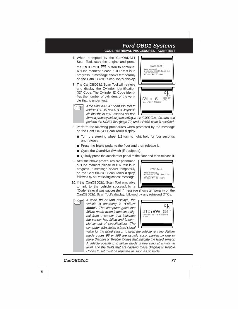
CanOBD2&1 77
E
Ford OBD1 SystemsCODE RETRIEVAL PROCEDURES - KOER TEST
6. When prompted by the CanOBD2&1Scan Tool, start the engine and press
the ENTER/LD button to continue.A "One moment please KOER test is inprogress..." message shows temporarilyon the CanOBD2&1 Scan Tool's display.
7. The CanOBD2&1 Scan Tool will retrieveand display the Cylinder Identification(ID) Code. The Cylinder ID Code identi-fies the number of cylinders of the vehi-cle that is under test.
If the CanOBD2&1 Scan Tool fails toretrieve CYL ID and DTCs, its possi-ble that the KOEO Test was not per-formed properly before proceeding to the KOER Test.Go back andperform the KOEO Test (page 70) until a PASS code is obtained.
8. Perform the following procedures when prompted by the messageon the CanOBD2&1 Scan Tool's display.
■ Turn the steering wheel 1/2 turn to right, hold for four secondsand release.
■ Press the brake pedal to the floor and then release it.
■ Cycle the Overdrive Switch (if equipped).
■ Quickly press the accelerator pedal to the floor and then release it.
9. After the above procedures are performeda "One moment please KOER test is inprogress..." message shows temporarilyon the CanOBD2&1 Scan Tool's display,followed by a "Retrieving codes" message.
10. If the CanOBD2&1 Scan Tool was ableto link to the vehicle successfully, a“Code retrieval was successful...” message shows temporarily on theCanOBD2&1 Scan Tool’s display, followed by any retrieved DTCs.
If code 98 or 998 displays, thevehicle is operating in "FailureMode". The computer goes intofailure mode when it detects a sig-nal from a sensor that indicatesthe sensor has failed and is com-pletely out of specifications. Thecomputer substitutes a fixed signalvalue for the failed sensor to keep the vehicle running. Failuremode codes 98 or 998 are usually accompanied by one ormore Diagnostic Trouble Codes that indicate the failed sensor.A vehicle operating in failure mode is operating at a minimallevel, and the faults that are causing these Diagnostic TroubleCodes to set must be repaired as soon as possible.
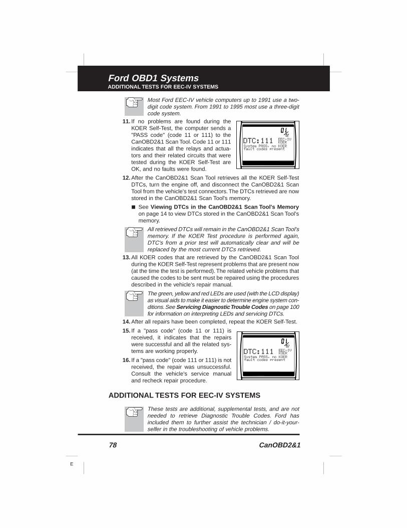
78 CanOBD2&1
E
Ford OBD1 SystemsADDITIONAL TESTS FOR EEC-IV SYSTEMS
Most Ford EEC-IV vehicle computers up to 1991 use a two-digit code system. From 1991 to 1995 most use a three-digitcode system.
11. If no problems are found during theKOER Self-Test, the computer sends a"PASS code" (code 11 or 111) to theCanOBD2&1 Scan Tool. Code 11 or 111indicates that all the relays and actua-tors and their related circuits that weretested during the KOER Self-Test areOK, and no faults were found.
12. After the CanOBD2&1 Scan Tool retrieves all the KOER Self-TestDTCs, turn the engine off, and disconnect the CanOBD2&1 ScanTool from the vehicle's test connectors. The DTCs retrieved are nowstored in the CanOBD2&1 Scan Tool's memory.
■ See Viewing DTCs in the CanOBD2&1 Scan Tool's Memoryon page 14 to view DTCs stored in the CanOBD2&1 Scan Tool'smemory.
All retrieved DTCs will remain in the CanOBD2&1 Scan Tool'smemory. If the KOER Test procedure is performed again,DTC's from a prior test will automatically clear and will bereplaced by the most current DTCs retrieved.
13. All KOER codes that are retrieved by the CanOBD2&1 Scan Toolduring the KOER Self-Test represent problems that are present now(at the time the test is performed). The related vehicle problems thatcaused the codes to be sent must be repaired using the proceduresdescribed in the vehicle's repair manual.
The green, yellow and red LEDs are used (with the LCD display)as visual aids to make it easier to determine engine system con-ditions. See Servicing Diagnostic Trouble Codes on page 100for information on interpreting LEDs and servicing DTCs.
14. After all repairs have been completed, repeat the KOER Self-Test.
15. If a "pass code" (code 11 or 111) isreceived, it indicates that the repairswere successful and all the related sys-tems are working properly.
16. If a "pass code" (code 111 or 111) is notreceived, the repair was unsuccessful.Consult the vehicle's service manualand recheck repair procedure.
ADDITIONAL TESTS FOR EEC-IV SYSTEMS
These tests are additional, supplemental tests, and are notneeded to retrieve Diagnostic Trouble Codes. Ford hasincluded them to further assist the technician / do-it-your-selfer in the troubleshooting of vehicle problems.
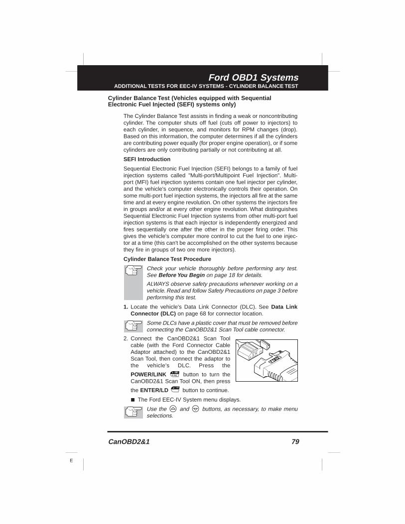
CanOBD2&1 79
E
Ford OBD1 SystemsADDITIONAL TESTS FOR EEC-IV SYSTEMS - CYLINDER BALANCE TEST
Cylinder Balance Test (Vehicles equipped with SequentialElectronic Fuel Injected (SEFI) systems only)
The Cylinder Balance Test assists in finding a weak or noncontributingcylinder. The computer shuts off fuel (cuts off power to injectors) toeach cylinder, in sequence, and monitors for RPM changes (drop).Based on this information, the computer determines if all the cylindersare contributing power equally (for proper engine operation), or if somecylinders are only contributing partially or not contributing at all.
SEFI Introduction
Sequential Electronic Fuel Injection (SEFI) belongs to a family of fuelinjection systems called "Multi-port/Multipoint Fuel Injection". Multi-port (MFI) fuel injection systems contain one fuel injector per cylinder,and the vehicle's computer electronically controls their operation. Onsome multi-port fuel injection systems, the injectors all fire at the sametime and at every engine revolution. On other systems the injectors firein groups and/or at every other engine revolution. What distinguishesSequential Electronic Fuel Injection systems from other multi-port fuelinjection systems is that each injector is independently energized andfires sequentially one after the other in the proper firing order. Thisgives the vehicle's computer more control to cut the fuel to one injec-tor at a time (this can't be accomplished on the other systems becausethey fire in groups of two ore more injectors).
Cylinder Balance Test Procedure
Check your vehicle thoroughly before performing any test.See Before You Begin on page 18 for details.
ALWAYS observe safety precautions whenever working on avehicle. Read and follow Safety Precautions on page 3 beforeperforming this test.
1. Locate the vehicle's Data Link Connector (DLC). See Data LinkConnector (DLC) on page 68 for connector location.
Some DLCs have a plastic cover that must be removed beforeconnecting the CanOBD2&1 Scan Tool cable connector.
2. Connect the CanOBD2&1 Scan Toolcable (with the Ford Connector CableAdaptor attached) to the CanOBD2&1Scan Tool, then connect the adaptor tothe vehicle's DLC. Press the
POWER/LINK button to turn theCanOBD2&1 Scan Tool ON, then press
the ENTER/LD button to continue.
■ The Ford EEC-IV System menu displays.
Use the and buttons, as necessary, to make menuselections.
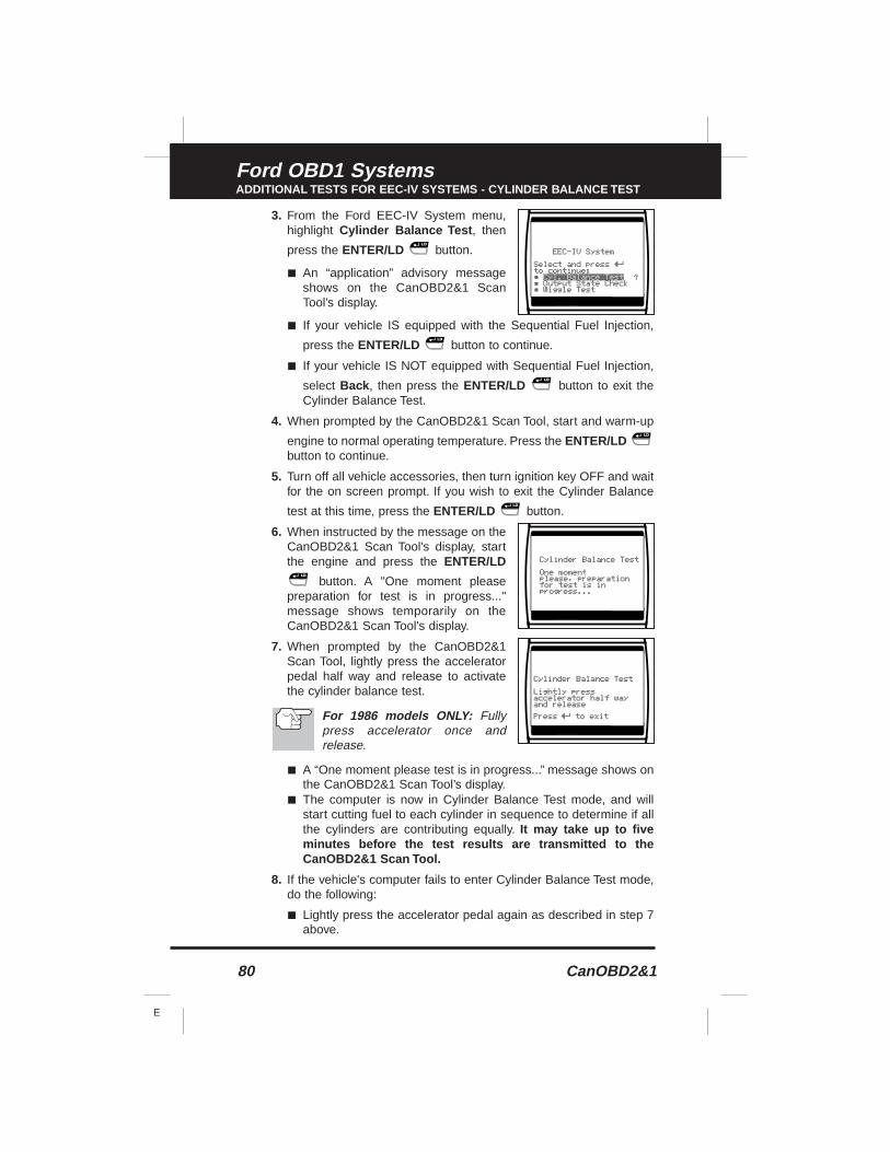
80 CanOBD2&1
E
Ford OBD1 SystemsADDITIONAL TESTS FOR EEC-IV SYSTEMS - CYLINDER BALANCE TEST
3. From the Ford EEC-IV System menu,highlight Cylinder Balance Test , then
press the ENTER/LD button.
■ An “application” advisory messageshows on the CanOBD2&1 ScanTool’s display.
■ If your vehicle IS equipped with the Sequential Fuel Injection,
press the ENTER/LD button to continue.
■ If your vehicle IS NOT equipped with Sequential Fuel Injection,
select Back , then press the ENTER/LD button to exit theCylinder Balance Test.
4. When prompted by the CanOBD2&1 Scan Tool, start and warm-up
engine to normal operating temperature. Press the ENTER/LDbutton to continue.
5. Turn off all vehicle accessories, then turn ignition key OFF and waitfor the on screen prompt. If you wish to exit the Cylinder Balance
test at this time, press the ENTER/LD button.
6. When instructed by the message on theCanOBD2&1 Scan Tool's display, startthe engine and press the ENTER/LD
button. A "One moment pleasepreparation for test is in progress..."message shows temporarily on theCanOBD2&1 Scan Tool's display.
7. When prompted by the CanOBD2&1Scan Tool, lightly press the acceleratorpedal half way and release to activatethe cylinder balance test.
For 1986 models ONLY: Fullypress accelerator once andrelease.
■ A “One moment please test is in progress...” message shows onthe CanOBD2&1 Scan Tool’s display.
■ The computer is now in Cylinder Balance Test mode, and willstart cutting fuel to each cylinder in sequence to determine if allthe cylinders are contributing equally. It may take up to fiveminutes before the test results are transmitted to theCanOBD2&1 Scan Tool.
8. If the vehicle's computer fails to enter Cylinder Balance Test mode,do the following:
■ Lightly press the accelerator pedal again as described in step 7above.
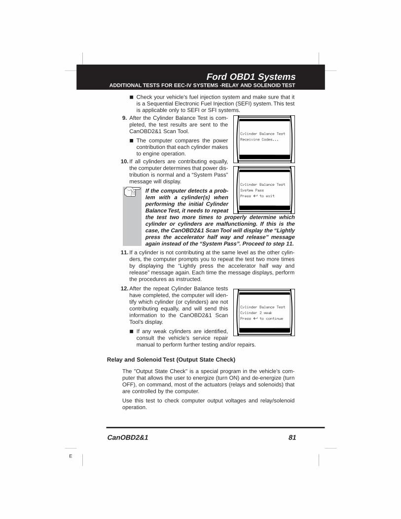
CanOBD2&1 81
E
Ford OBD1 SystemsADDITIONAL TESTS FOR EEC-IV SYSTEMS -RELAY AND SOLENOID TEST
■ Check your vehicle's fuel injection system and make sure that itis a Sequential Electronic Fuel Injection (SEFI) system. This testis applicable only to SEFI or SFI systems.
9. After the Cylinder Balance Test is com-pleted, the test results are sent to theCanOBD2&1 Scan Tool.
■ The computer compares the powercontribution that each cylinder makesto engine operation.
10. If all cylinders are contributing equally,the computer determines that power dis-tribution is normal and a “System Pass”message will display.
If the computer detects a prob-lem with a cylinder(s) whenperforming the initial CylinderBalance Test, it needs to repeatthe test two more times to properly determine whichcylinder or cylinders are malfunctioning. If this is thecase, the CanOBD2&1 Scan Tool will display the “Lightlypress the accelerator half way and release” messageagain instead of the “System Pass”. Proceed to step 11.
11. If a cylinder is not contributing at the same level as the other cylin-ders, the computer prompts you to repeat the test two more timesby displaying the “Lightly press the accelerator half way andrelease” message again. Each time the message displays, performthe procedures as instructed.
12. After the repeat Cylinder Balance testshave completed, the computer will iden-tify which cylinder (or cylinders) are notcontributing equally, and will send thisinformation to the CanOBD2&1 ScanTool’s display.
■ If any weak cylinders are identified,consult the vehicle’s service repairmanual to perform further testing and/or repairs.
Relay and Solenoid Test (Output State Check)
The "Output State Check" is a special program in the vehicle's com-puter that allows the user to energize (turn ON) and de-energize (turnOFF), on command, most of the actuators (relays and solenoids) thatare controlled by the computer.
Use this test to check computer output voltages and relay/solenoidoperation.
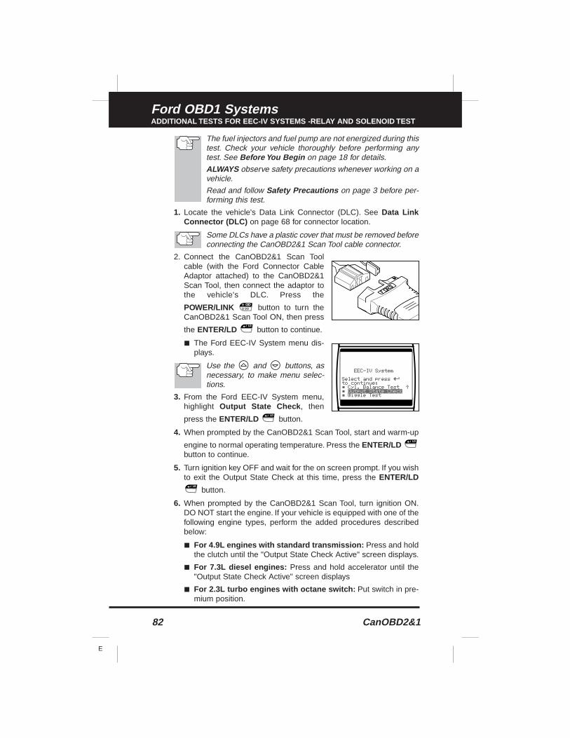
82 CanOBD2&1
E
Ford OBD1 SystemsADDITIONAL TESTS FOR EEC-IV SYSTEMS -RELAY AND SOLENOID TEST
The fuel injectors and fuel pump are not energized during thistest. Check your vehicle thoroughly before performing anytest. See Before You Begin on page 18 for details.
ALWAYS observe safety precautions whenever working on avehicle.
Read and follow Safety Precautions on page 3 before per-forming this test.
1. Locate the vehicle's Data Link Connector (DLC). See Data LinkConnector (DLC) on page 68 for connector location.
Some DLCs have a plastic cover that must be removed beforeconnecting the CanOBD2&1 Scan Tool cable connector.
2. Connect the CanOBD2&1 Scan Toolcable (with the Ford Connector CableAdaptor attached) to the CanOBD2&1Scan Tool, then connect the adaptor tothe vehicle's DLC. Press the
POWER/LINK button to turn theCanOBD2&1 Scan Tool ON, then press
the ENTER/LD button to continue.
■ The Ford EEC-IV System menu dis-plays.
Use the and buttons, asnecessary, to make menu selec-tions.
3. From the Ford EEC-IV System menu,highlight Output State Check , then
press the ENTER/LD button.
4. When prompted by the CanOBD2&1 Scan Tool, start and warm-up
engine to normal operating temperature. Press the ENTER/LDbutton to continue.
5. Turn ignition key OFF and wait for the on screen prompt. If you wishto exit the Output State Check at this time, press the ENTER/LD
button.
6. When prompted by the CanOBD2&1 Scan Tool, turn ignition ON.DO NOT start the engine. If your vehicle is equipped with one of thefollowing engine types, perform the added procedures describedbelow:
■ For 4.9L engines with standard transmission: Press and holdthe clutch until the "Output State Check Active" screen displays.
■ For 7.3L diesel engines: Press and hold accelerator until the"Output State Check Active" screen displays
■ For 2.3L turbo engines with octane switch: Put switch in pre-mium position.
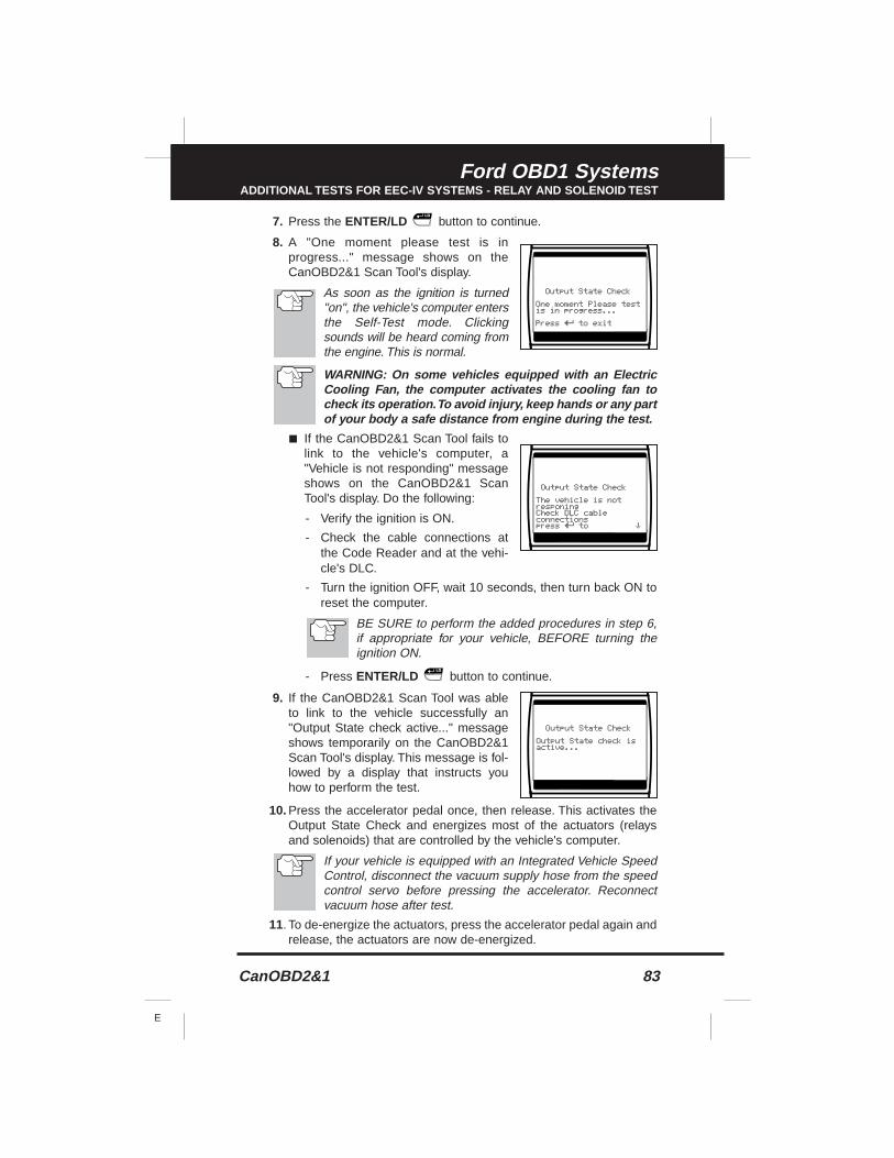
CanOBD2&1 83
E
Ford OBD1 SystemsADDITIONAL TESTS FOR EEC-IV SYSTEMS - RELAY AND SOLENOID TEST
7. Press the ENTER/LD button to continue.
8. A "One moment please test is inprogress..." message shows on theCanOBD2&1 Scan Tool's display.
As soon as the ignition is turned"on", the vehicle's computer entersthe Self-Test mode. Clickingsounds will be heard coming fromthe engine. This is normal.
WARNING: On some vehicles equipped with an ElectricCooling Fan, the computer activates the cooling fan tocheck its operation.To avoid injury, keep hands or any partof your body a safe distance from engine during the test.
■ If the CanOBD2&1 Scan Tool fails tolink to the vehicle's computer, a"Vehicle is not responding" messageshows on the CanOBD2&1 ScanTool's display. Do the following:
- Verify the ignition is ON.
- Check the cable connections atthe Code Reader and at the vehi-cle's DLC.
- Turn the ignition OFF, wait 10 seconds, then turn back ON toreset the computer.
BE SURE to perform the added procedures in step 6,if appropriate for your vehicle, BEFORE turning theignition ON.
- Press ENTER/LD button to continue.
9. If the CanOBD2&1 Scan Tool was ableto link to the vehicle successfully an"Output State check active..." messageshows temporarily on the CanOBD2&1Scan Tool's display. This message is fol-lowed by a display that instructs youhow to perform the test.
10. Press the accelerator pedal once, then release. This activates theOutput State Check and energizes most of the actuators (relaysand solenoids) that are controlled by the vehicle's computer.
If your vehicle is equipped with an Integrated Vehicle SpeedControl, disconnect the vacuum supply hose from the speedcontrol servo before pressing the accelerator. Reconnectvacuum hose after test.
11. To de-energize the actuators, press the accelerator pedal again andrelease, the actuators are now de-energized.
84 CanOBD2&1
E
Ford OBD1 SystemsADDITIONAL TESTS FOR EEC-IV SYSTEMS -WIGGLE TEST
12. The procedure can be repeated as many times as desired by press-ing and releasing the accelerator pedal to energize and de-energizethe actuators.
13. Consult the vehicle's service repair manual for a list of actuators(solenoids and relays) controlled by the computer that apply to thevehicle under test, and which actuators should energize and de-energize when performing the Output State Check. All applicableactuators should be on when energized and off when de-energized.
14. If an actuator is not responding to the Output State Check, followthe procedures described in the vehicle's service manual to checkcomputer actuator output circuit voltages and/or grounds.
15. The Output State Check will stay active as long as desired. To quitthe Output State Check, turn the ignition OFF and disconnect theCanOBD2&1 Scan Tool from the vehicle.
Wiggle Test
Since any DTC’s from Wiggle Test results are saved inContinuous Memory, it is suggested that you clear any DTC’sin Continuous Memory before performing Wiggle Test (seeErasing DTC’s on page 102 for procedures). This way youstart with a clean slate, and any faults detected during theprocedure will be related to that particular circuit tested.
Use this test to check for intermittent faults in some circuits.
Circuits Tested:
1984 & Newer - Air Charge Temp Sensor (ACT), Barometer PressureSensor (BP), Engine Coolant Temp Sensor (ECT), Exhaust GasOxygen Sensor (EGO), EGR Valve Position Sensor (EVP), ManifoldAbsolute Pressure (MAP), Throttle Position Sensor (TP), Vane AirTemp Sensor (VAT)
1985 & Newer - Vane Air Flow Sensor (VAF)
1986 & Newer - Pressure Feedback EGR Sensor (PFE)
1990 & Newer - Exhaust Gas Oxygen Sensor (EGO), IgnitionDiagnostic Monitor (IDM) (DIS or Dual Plug DIS only), Idle TrackingSwitch (ITS), Mass Air Flow Sensor (MAF)
ALWAYS observe safety precautions whenever working on avehicle. Read and follow Safety Precautions on page 3before performing this test.
1. Locate the vehicle's Data Link Connector (DLC). See Data LinkConnector (DLC) on page 68 for connector location.
Some DLCs have a plastic cover that must be removed beforeconnecting the CanOBD2&1 Scan Tool cable connector.
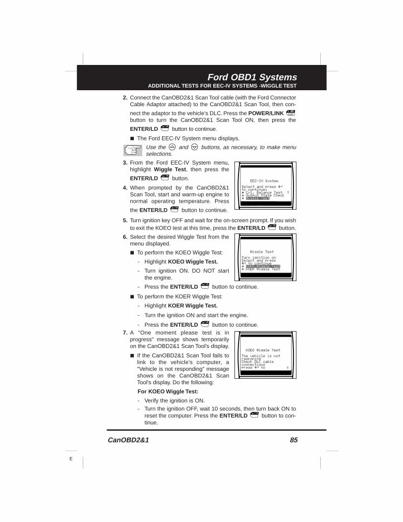
CanOBD2&1 85
E
Ford OBD1 SystemsADDITIONAL TESTS FOR EEC-IV SYSTEMS -WIGGLE TEST
2. Connect the CanOBD2&1 Scan Tool cable (with the Ford ConnectorCable Adaptor attached) to the CanOBD2&1 Scan Tool, then con-
nect the adaptor to the vehicle's DLC. Press the POWER/LINKbutton to turn the CanOBD2&1 Scan Tool ON, then press the
ENTER/LD button to continue.
■ The Ford EEC-IV System menu displays.
Use the and buttons, as necessary, to make menuselections.
3. From the Ford EEC-IV System menu,highlight Wiggle Test , then press the
ENTER/LD button.
4. When prompted by the CanOBD2&1Scan Tool, start and warm-up engine tonormal operating temperature. Press
the ENTER/LD button to continue.
5. Turn ignition key OFF and wait for the on-screen prompt. If you wishto exit the KOEO test at this time, press the ENTER/LD button.
6. Select the desired Wiggle Test from themenu displayed.
■ To perform the KOEO Wiggle Test:
- Highlight KOEO Wiggle Test.
- Turn ignition ON. DO NOT startthe engine.
- Press the ENTER/LD button to continue.
■ To perform the KOER Wiggle Test:
- Highlight KOER Wiggle Test.
- Turn the ignition ON and start the engine.
- Press the ENTER/LD button to continue.7. A "One moment please test is in
progress" message shows temporarilyon the CanOBD2&1 Scan Tool’s display.
■ If the CanOBD2&1 Scan Tool fails tolink to the vehicle's computer, a"Vehicle is not responding" messageshows on the CanOBD2&1 ScanTool's display. Do the following:
For KOEO Wiggle Test:
- Verify the ignition is ON.
- Turn the ignition OFF, wait 10 seconds, then turn back ON toreset the computer. Press the ENTER/LD button to con-tinue.
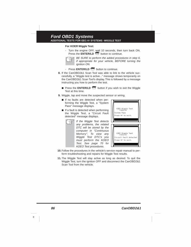
86 CanOBD2&1
E
Ford OBD1 SystemsADDITIONAL TESTS FOR EEC-IV SYSTEMS -WIGGLE TEST
For KOER Wiggle Test:
- Turn the engine OFF, wait 10 seconds, then turn back ON.Press the ENTER/LD button to continue.
BE SURE to perform the added procedures in step 6,if appropriate for your vehicle, BEFORE turning theignition ON.
- Press ENTER/LD button to continue.8. If the CanOBD2&1 Scan Tool was able to link to the vehicle suc-
cessfully, a "Wiggle test is active..." message shows temporarily onthe CanOBD2&1 Scan Tool’s display. This is followed by a messageinstructing you how to perform the test.
■ Press the ENTER/LD button if you wish to exit the WiggleTest at this time.
9. Wiggle, tap and move the suspected sensor or wiring.
■ If no faults are detected when per-forming the Wiggle Test, a "SystemPass" message displays.
■ If a fault is detected when performingthe Wiggle Test, a "Circuit Faultdetected" message displays.
If the Wiggle Test detectsany problems, the relatedDTC will be stored by thecomputer in "ContinuousMemory". To view anyWiggle Test DTC’s youmust perform the KOEOTest. See page 70 forKOEO Test procedures.
10. Follow the procedures in the vehicle's service repair manual to per-form troubleshooting and repairs for Wiggle Test results.
11. The Wiggle Test will stay active as long as desired. To quit theWiggle Test, turn the ignition OFF and disconnect the CanOBD2&1Scan Tool from the vehicle.
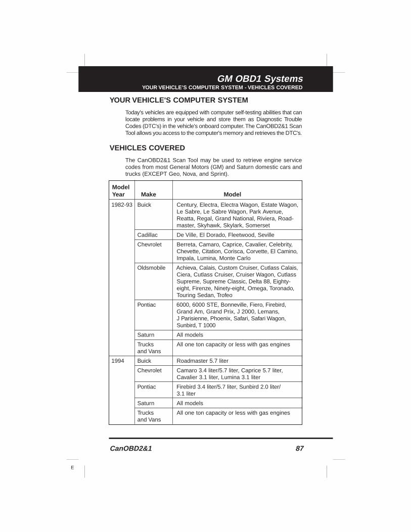
CanOBD2&1 87
E
GM OBD1 SystemsYOUR VEHICLE’S COMPUTER SYSTEM - VEHICLES COVERED
YOUR VEHICLE'S COMPUTER SYSTEM
Today's vehicles are equipped with computer self-testing abilities that canlocate problems in your vehicle and store them as Diagnostic TroubleCodes (DTC's) in the vehicle's onboard computer.The CanOBD2&1 ScanTool allows you access to the computer's memory and retrieves the DTC's.
VEHICLES COVERED
The CanOBD2&1 Scan Tool may be used to retrieve engine servicecodes from most General Motors (GM) and Saturn domestic cars andtrucks (EXCEPT Geo, Nova, and Sprint).
ModelYear Make Model
1982-93 Buick Century, Electra, Electra Wagon, Estate Wagon,Le Sabre, Le Sabre Wagon, Park Avenue,Reatta, Regal, Grand National, Riviera, Road-master, Skyhawk, Skylark, Somerset
Cadillac De Ville, El Dorado, Fleetwood, Seville
Chevrolet Berreta, Camaro, Caprice, Cavalier, Celebrity,Chevette, Citation, Corisca, Corvette, El Camino,Impala, Lumina, Monte Carlo
Oldsmobile Achieva, Calais, Custom Cruiser, Cutlass Calais,Ciera, Cutlass Cruiser, Cruiser Wagon, CutlassSupreme, Supreme Classic, Delta 88, Eighty-eight, Firenze, Ninety-eight, Omega, Toronado,Touring Sedan, Trofeo
Pontiac 6000, 6000 STE, Bonneville, Fiero, Firebird,Grand Am, Grand Prix, J 2000, Lemans,J Parisienne, Phoenix, Safari, Safari Wagon,Sunbird, T 1000
Saturn All models
Trucks All one ton capacity or less with gas enginesand Vans
1994 Buick Roadmaster 5.7 liter
Chevrolet Camaro 3.4 liter/5.7 liter, Caprice 5.7 liter,Cavalier 3.1 liter, Lumina 3.1 liter
Pontiac Firebird 3.4 liter/5.7 liter, Sunbird 2.0 liter/3.1 liter
Saturn All models
Trucks All one ton capacity or less with gas enginesand Vans
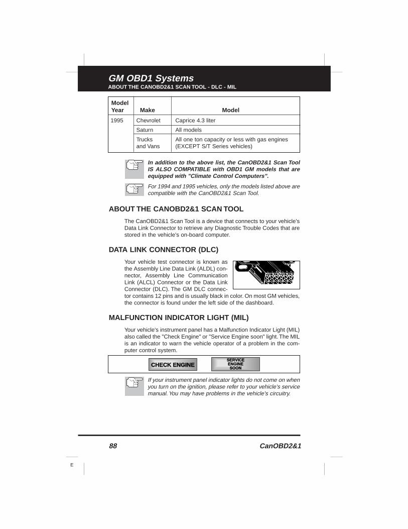
88 CanOBD2&1
E
GM OBD1 SystemsABOUT THE CANOBD2&1 SCAN TOOL - DLC - MIL
In addition to the above list, the CanOBD2&1 Scan ToolIS ALSO COMPATIBLE with OBD1 GM models that areequipped with "Climate Control Computers".
For 1994 and 1995 vehicles, only the models listed above arecompatible with the CanOBD2&1 Scan Tool.
ABOUT THE CANOBD2&1 SCAN TOOL
The CanOBD2&1 Scan Tool is a device that connects to your vehicle'sData Link Connector to retrieve any Diagnostic Trouble Codes that arestored in the vehicle's on-board computer.
DATA LINK CONNECTOR (DLC)
Your vehicle test connector is known asthe Assembly Line Data Link (ALDL) con-nector, Assembly Line CommunicationLink (ALCL) Connector or the Data LinkConnector (DLC). The GM DLC connec-tor contains 12 pins and is usually black in color. On most GM vehicles,the connector is found under the left side of the dashboard.
MALFUNCTION INDICATOR LIGHT (MIL)
Your vehicle's instrument panel has a Malfunction Indicator Light (MIL)also called the "Check Engine" or "Service Engine soon" light. The MILis an indicator to warn the vehicle operator of a problem in the com-puter control system.
If your instrument panel indicator lights do not come on whenyou turn on the ignition, please refer to your vehicle's servicemanual. You may have problems in the vehicle's circuitry.
ModelYear Make Model
1995 Chevrolet Caprice 4.3 liter
Saturn All models
Trucks All one ton capacity or less with gas enginesand Vans (EXCEPT S/T Series vehicles)
CHECK ENGINESERVICEENGINESOON
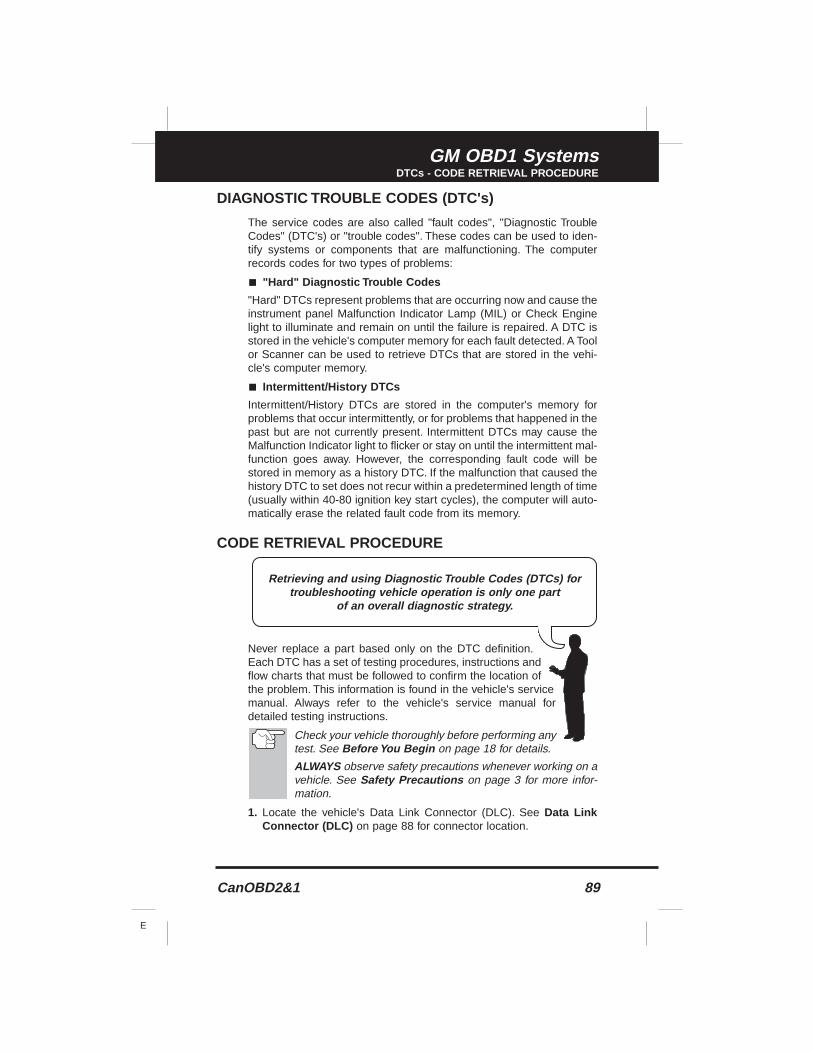
CanOBD2&1 89
E
GM OBD1 SystemsDTCs - CODE RETRIEVAL PROCEDURE
DIAGNOSTIC TROUBLE CODES (DTC's)
The service codes are also called "fault codes", "Diagnostic TroubleCodes" (DTC's) or "trouble codes". These codes can be used to iden-tify systems or components that are malfunctioning. The computerrecords codes for two types of problems:
■ "Hard" Diagnostic Trouble Codes
"Hard" DTCs represent problems that are occurring now and cause theinstrument panel Malfunction Indicator Lamp (MIL) or Check Enginelight to illuminate and remain on until the failure is repaired. A DTC isstored in the vehicle's computer memory for each fault detected. A Toolor Scanner can be used to retrieve DTCs that are stored in the vehi-cle's computer memory.
■ Intermittent/History DTCs
Intermittent/History DTCs are stored in the computer's memory forproblems that occur intermittently, or for problems that happened in thepast but are not currently present. Intermittent DTCs may cause theMalfunction Indicator light to flicker or stay on until the intermittent mal-function goes away. However, the corresponding fault code will bestored in memory as a history DTC. If the malfunction that caused thehistory DTC to set does not recur within a predetermined length of time(usually within 40-80 ignition key start cycles), the computer will auto-matically erase the related fault code from its memory.
CODE RETRIEVAL PROCEDURE
Never replace a part based only on the DTC definition.Each DTC has a set of testing procedures, instructions andflow charts that must be followed to confirm the location ofthe problem. This information is found in the vehicle's servicemanual. Always refer to the vehicle's service manual fordetailed testing instructions.
Check your vehicle thoroughly before performing anytest. See Before You Begin on page 18 for details.
ALWAYS observe safety precautions whenever working on avehicle. See Safety Precautions on page 3 for more infor-mation.
1. Locate the vehicle's Data Link Connector (DLC). See Data LinkConnector (DLC) on page 88 for connector location.
Retrieving and using Diagnostic Trouble Codes (DTCs) fortroubleshooting vehicle operation is only one part
of an overall diagnostic strategy.
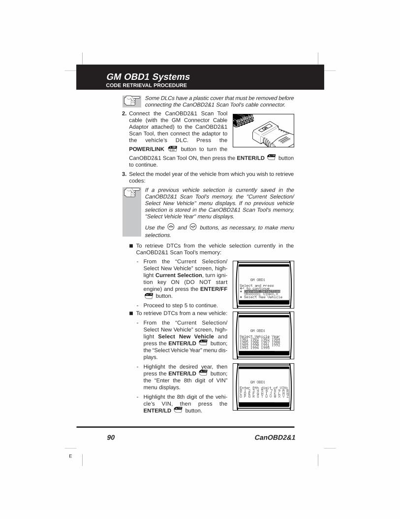
90 CanOBD2&1
E
GM OBD1 SystemsCODE RETRIEVAL PROCEDURE
Some DLCs have a plastic cover that must be removed beforeconnecting the CanOBD2&1 Scan Tool's cable connector.
2. Connect the CanOBD2&1 Scan Toolcable (with the GM Connector CableAdaptor attached) to the CanOBD2&1Scan Tool, then connect the adaptor tothe vehicle’s DLC. Press the
POWER/LINK button to turn the
CanOBD2&1 Scan Tool ON, then press the ENTER/LD buttonto continue.
3. Select the model year of the vehicle from which you wish to retrievecodes:
If a previous vehicle selection is currently saved in theCanOBD2&1 Scan Tool's memory, the "Current Selection/Select New Vehicle" menu displays. If no previous vehicleselection is stored in the CanOBD2&1 Scan Tool's memory,"Select Vehicle Year" menu displays.
Use the and buttons, as necessary, to make menuselections.
■ To retrieve DTCs from the vehicle selection currently in theCanOBD2&1 Scan Tool’s memory:
- From the “Current Selection/Select New Vehicle” screen, high-light Current Selection , turn igni-tion key ON (DO NOT startengine) and press the ENTER/FF
button.
- Proceed to step 5 to continue.■ To retrieve DTCs from a new vehicle:
- From the “Current Selection/Select New Vehicle” screen, high-light Select New Vehicle andpress the ENTER/LD button;the “Select Vehicle Year” menu dis-plays.
- Highlight the desired year, thenpress the ENTER/LD button;the “Enter the 8th digit of VIN”menu displays.
- Highlight the 8th digit of the vehi-cle’s VIN, then press theENTER/LD button.
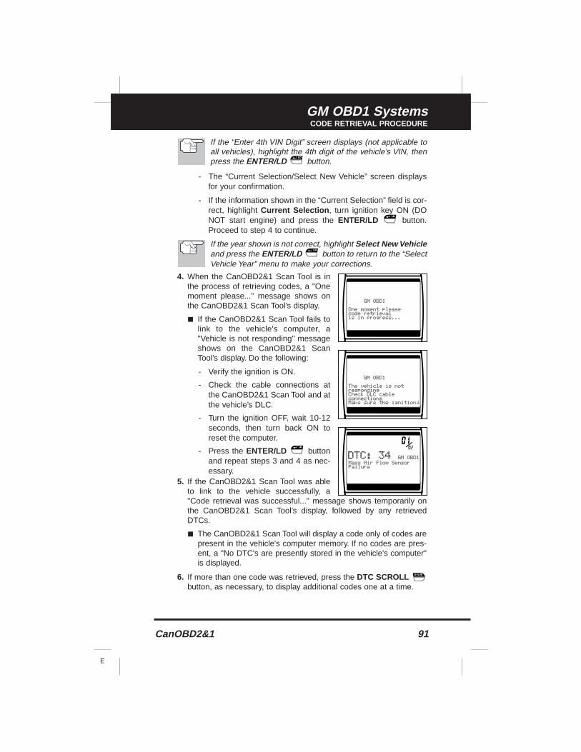
CanOBD2&1 91
E
GM OBD1 SystemsCODE RETRIEVAL PROCEDURE
If the “Enter 4th VIN Digit” screen displays (not applicable toall vehicles), highlight the 4th digit of the vehicle’s VIN, thenpress the ENTER/LD button.
- The “Current Selection/Select New Vehicle” screen displaysfor your confirmation.
- If the information shown in the “Current Selection” field is cor-rect, highlight Current Selection , turn ignition key ON (DONOT start engine) and press the ENTER/LD button.Proceed to step 4 to continue.
If the year shown is not correct, highlight Select New Vehicleand press the ENTER/LD button to return to the “SelectVehicle Year” menu to make your corrections.
4. When the CanOBD2&1 Scan Tool is inthe process of retrieving codes, a "Onemoment please..." message shows onthe CanOBD2&1 Scan Tool’s display.
■ If the CanOBD2&1 Scan Tool fails tolink to the vehicle's computer, a"Vehicle is not responding" messageshows on the CanOBD2&1 ScanTool’s display. Do the following:
- Verify the ignition is ON.
- Check the cable connections atthe CanOBD2&1 Scan Tool and atthe vehicle’s DLC.
- Turn the ignition OFF, wait 10-12seconds, then turn back ON toreset the computer.
- Press the ENTER/LD buttonand repeat steps 3 and 4 as nec-essary.
5. If the CanOBD2&1 Scan Tool was ableto link to the vehicle successfully, a"Code retrieval was successful..." message shows temporarily onthe CanOBD2&1 Scan Tool’s display, followed by any retrievedDTCs.
■ The CanOBD2&1 Scan Tool will display a code only of codes arepresent in the vehicle's computer memory. If no codes are pres-ent, a "No DTC's are presently stored in the vehicle's computer"is displayed.
6. If more than one code was retrieved, press the DTC SCROLLbutton, as necessary, to display additional codes one at a time.
92 CanOBD2&1
E
GM OBD1 SystemsCODE RETRIEVAL PROCEDURE
In the case of long code definitions, a small arrow is shownin the upper.lower right-hand corner of the code display areato indicate the presence of additional information. Use the
and buttons, as necessary, to view the additionalinformation.
Code 12 will always be present and it has one of the following mean-ings:
■ If code 12 is the only DTC retrieved and your vehicle "STARTS OK"then code 12 indicates system "PASS" and all computer controlsystems are functioning properly.
■ If code 12 is present and your vehicle "DOES NOT START", then itmay indicate a problem with the ignition control system.
7. Disconnect the CanOBD2&1 Scan Tool from the vehicle and turnthe ignition key OFF.
8. To prolong battery life, the CanOBD2&1 Scan Tool automaticallyshuts "Off" after approximately three minutes with no button activi-ty. The DTCs retrieved will remain in the CanOBD2&1 Scan Tool'smemory, and may be viewed at any time. If the CanOBD2&1 ScanTool’s batteries are removed, or if the CanOBD2&1 Scan Tool is re-linked to a vehicle to retrieve codes, any prior codes in its memoryare automatically cleared.
■ See Viewing DTCs in the CanOBD2&1 Scan Tool’s Memoryon page 14 to view DTCs stored in the CanOBD2&1 Scan Tool’smemory.
9. Follow the testing and repair procedures outlined in the vehicle'sservice repair manual to correct "hard" DTCs. Codes should beaddressed and eliminated in the order they were received, erasing(see Erasing DTC's on page 102) and retesting after each repair ismade to be sure the fault was eliminated. Code 12 will appear alonewhen no other fault codes are present.
■ It may be necessary to test drive the vehicle to reset "hard" faultcodes 13, 15, 24, 44, 45, and 55 after they have been erased.
Whenever codes 51, 52, 54, or 55 are displayed with othercodes, troubleshoot and eliminate the "50 Series" codes first,then proceed with the lower numbered codes.
The green, yellow and red LEDs are used (with the LCD dis-play) as visual aids to make it easier to determine engine sys-tem conditions. See Servicing Diagnostic Trouble Codeson page 100 for information on interpreting LEDs and servic-ing DTCs.
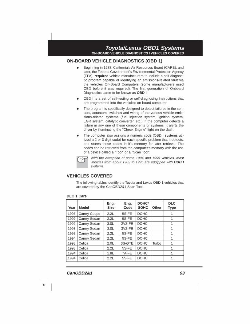
CanOBD2&1 93
E
Toyota/Lexus OBD1 SystemsON-BOARD VEHICLE DIAGNOSTICS / VEHICLES COVERED
ON-BOARD VEHICLE DIAGNOSTICS (OBD 1)
• Beginning in 1988, California's Air Resources Board (CARB), andlater, the Federal Government's Environmental Protection Agency(EPA), required vehicle manufacturers to include a self diagnos-tic program capable of identifying an emissions-related fault viathe vehicles On-Board Computers (some manufacturers usedOBD before it was required). The first generation of OnboardDiagnostics came to be known as OBD I.
• OBD I is a set of self-testing or self-diagnosing instructions thatare programmed into the vehicle's on-board computer.
• The program is specifically designed to detect failures in the sen-sors, actuators, switches and wiring of the various vehicle emis-sions-related systems (fuel injection system, ignition system,EGR system, catalytic converter, etc.). If the computer detects afailure in any one of these components or systems, it alerts thedriver by illuminating the "Check Engine" light on the dash.
• The computer also assigns a numeric code (OBD I systems uti-lized a 2 or 3 digit code) for each specific problem that it detects,and stores these codes in it's memory for later retrieval. Thecodes can be retrieved from the computer's memory with the useof a device called a "Tool" or a "Scan Tool".
With the exception of some 1994 and 1995 vehicles, mostvehicles from about 1982 to 1995 are equipped with OBD Isystems.
VEHICLES COVEREDThe following tables identify the Toyota and Lexus OBD 1 vehicles thatare covered by the CanOBD2&1 Scan Tool.
DLC 1 Cars
Eng. Eng. DOHC/ DLCYear Model Size Code SOHC Other Type
1995 Camry Coupe 2.2L 5S-FE DOHC 11992 Camry Sedan 2.2L 5S-FE DOHC 11992 Camry Sedan 3.0L 2VZ-FE DOHC 11993 Camry Sedan 3.0L 3VZ-FE DOHC 11993 Camry Sedan 2.2L 5S-FE DOHC 11994 Camry Sedan 2.2L 5S-FE DOHC 11993 Celica 2.0L 3S-GTE DOHC Turbo 11993 Celica 2.2L 5S-FE DOHC 11994 Celica 1.8L 7A-FE DOHC 11994 Celica 2.2L 5S-FE DOHC 1
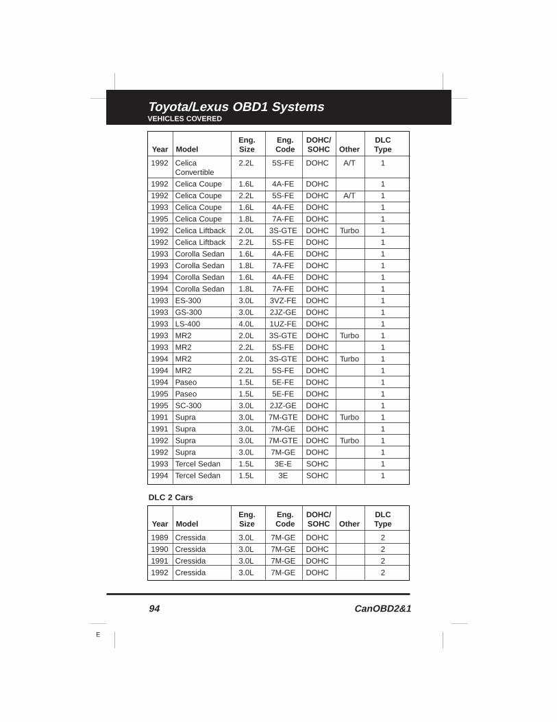
94 CanOBD2&1
E
Toyota/Lexus OBD1 SystemsVEHICLES COVERED
DLC 2 Cars
Eng. Eng. DOHC/ DLCYear Model Size Code SOHC Other Type
1992 Celica 2.2L 5S-FE DOHC A/T 1Convertible
1992 Celica Coupe 1.6L 4A-FE DOHC 1
1992 Celica Coupe 2.2L 5S-FE DOHC A/T 1
1993 Celica Coupe 1.6L 4A-FE DOHC 1
1995 Celica Coupe 1.8L 7A-FE DOHC 1
1992 Celica Liftback 2.0L 3S-GTE DOHC Turbo 1
1992 Celica Liftback 2.2L 5S-FE DOHC 1
1993 Corolla Sedan 1.6L 4A-FE DOHC 1
1993 Corolla Sedan 1.8L 7A-FE DOHC 1
1994 Corolla Sedan 1.6L 4A-FE DOHC 1
1994 Corolla Sedan 1.8L 7A-FE DOHC 1
1993 ES-300 3.0L 3VZ-FE DOHC 1
1993 GS-300 3.0L 2JZ-GE DOHC 1
1993 LS-400 4.0L 1UZ-FE DOHC 1
1993 MR2 2.0L 3S-GTE DOHC Turbo 1
1993 MR2 2.2L 5S-FE DOHC 1
1994 MR2 2.0L 3S-GTE DOHC Turbo 1
1994 MR2 2.2L 5S-FE DOHC 1
1994 Paseo 1.5L 5E-FE DOHC 1
1995 Paseo 1.5L 5E-FE DOHC 1
1995 SC-300 3.0L 2JZ-GE DOHC 1
1991 Supra 3.0L 7M-GTE DOHC Turbo 1
1991 Supra 3.0L 7M-GE DOHC 1
1992 Supra 3.0L 7M-GTE DOHC Turbo 1
1992 Supra 3.0L 7M-GE DOHC 1
1993 Tercel Sedan 1.5L 3E-E SOHC 1
1994 Tercel Sedan 1.5L 3E SOHC 1
Eng. Eng. DOHC/ DLCYear Model Size Code SOHC Other Type
1989 Cressida 3.0L 7M-GE DOHC 2
1990 Cressida 3.0L 7M-GE DOHC 2
1991 Cressida 3.0L 7M-GE DOHC 2
1992 Cressida 3.0L 7M-GE DOHC 2
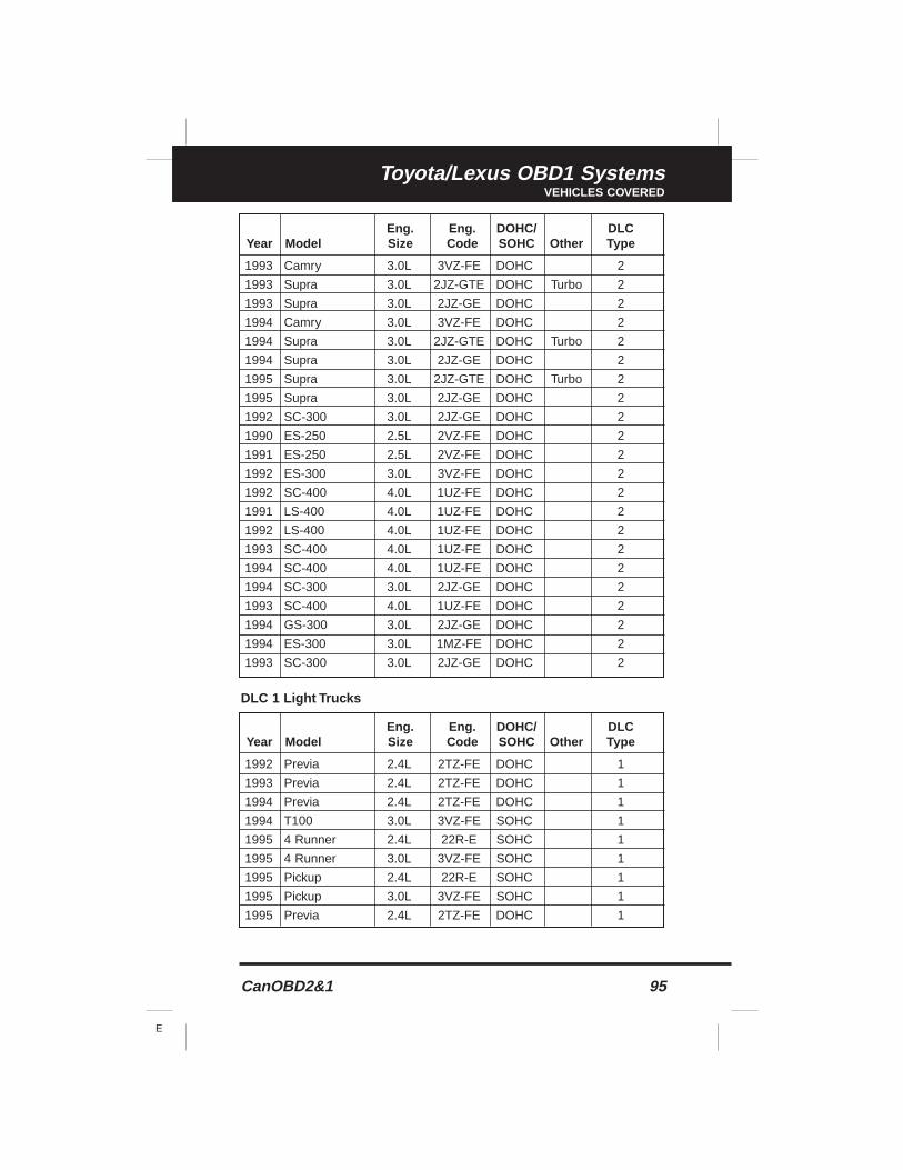
CanOBD2&1 95
E
Toyota/Lexus OBD1 SystemsVEHICLES COVERED
DLC 1 Light Trucks
Eng. Eng. DOHC/ DLCYear Model Size Code SOHC Other Type
1993 Camry 3.0L 3VZ-FE DOHC 2
1993 Supra 3.0L 2JZ-GTE DOHC Turbo 2
1993 Supra 3.0L 2JZ-GE DOHC 2
1994 Camry 3.0L 3VZ-FE DOHC 2
1994 Supra 3.0L 2JZ-GTE DOHC Turbo 2
1994 Supra 3.0L 2JZ-GE DOHC 2
1995 Supra 3.0L 2JZ-GTE DOHC Turbo 2
1995 Supra 3.0L 2JZ-GE DOHC 2
1992 SC-300 3.0L 2JZ-GE DOHC 2
1990 ES-250 2.5L 2VZ-FE DOHC 2
1991 ES-250 2.5L 2VZ-FE DOHC 2
1992 ES-300 3.0L 3VZ-FE DOHC 2
1992 SC-400 4.0L 1UZ-FE DOHC 2
1991 LS-400 4.0L 1UZ-FE DOHC 2
1992 LS-400 4.0L 1UZ-FE DOHC 2
1993 SC-400 4.0L 1UZ-FE DOHC 2
1994 SC-400 4.0L 1UZ-FE DOHC 2
1994 SC-300 3.0L 2JZ-GE DOHC 2
1993 SC-400 4.0L 1UZ-FE DOHC 2
1994 GS-300 3.0L 2JZ-GE DOHC 2
1994 ES-300 3.0L 1MZ-FE DOHC 2
1993 SC-300 3.0L 2JZ-GE DOHC 2
Eng. Eng. DOHC/ DLCYear Model Size Code SOHC Other Type
1992 Previa 2.4L 2TZ-FE DOHC 1
1993 Previa 2.4L 2TZ-FE DOHC 1
1994 Previa 2.4L 2TZ-FE DOHC 1
1994 T100 3.0L 3VZ-FE SOHC 1
1995 4 Runner 2.4L 22R-E SOHC 1
1995 4 Runner 3.0L 3VZ-FE SOHC 1
1995 Pickup 2.4L 22R-E SOHC 1
1995 Pickup 3.0L 3VZ-FE SOHC 1
1995 Previa 2.4L 2TZ-FE DOHC 1
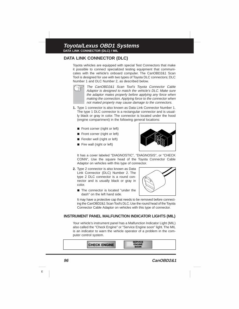
96 CanOBD2&1
E
Toyota/Lexus OBD1 SystemsDATA LINK CONNECTOR (DLC) / MIL
DATA LINK CONNECTOR (DLC)
Toyota vehicles are equipped with special Test Connectors that makeit possible to connect specialized testing equipment that communi-cates with the vehicle's onboard computer. The CanOBD2&1 ScanTool is designed for use with two types of Toyota DLC connectors; DLCNumber 1 and DLC Number 2, as described below.
The CanOBD2&1 Scan Tool's Toyota Connector CableAdaptor is designed to match the vehicle's DLC. Make surethe adaptor mates properly before applying any force whenmaking the connection. Applying force to the connector whennot mated properly may cause damage to the connectors.
1. Type 1 connector is also known as Data Link Connector Number 1.The type 1 DLC connector is a rectangular connector and is usual-ly black or gray in color. The connector is located under the hood(engine compartment) in the following general locations:
■ Front corner (right or left)
■ Front corner (right or left)
■ Fender well (right or left)
■ Fire wall (right or left)
It has a cover labeled "DIAGNOSTIC", "DIAGNOSIS", or "CHECKCONN", Use the square head of the Toyota Connector CableAdaptor on vehicles with this type of connector.
2. Type 2 connector is also known as DataLink Connector (DLC) Number 2. Thetype 2 DLC connector is a round con-nector and is usually black or gray incolor.
■ The connector is located "under thedash" on the left hand side.
It may have a protective cap that needs to be removed before connect-ing the CanOBD2&1 Scan Tool's DLC.Use the round head of the ToyotaConnector Cable Adaptor on vehicles with this type of connector.
INSTRUMENT PANEL MALFUNCTION INDICATOR LIGHTS (MIL)
Your vehicle's instrument panel has a Malfunction Indicator Light (MIL)also called the "Check Engine" or "Service Engine soon" light. The MILis an indicator to warn the vehicle operator of a problem in the com-puter control system.
CHECK ENGINESERVICEENGINESOON
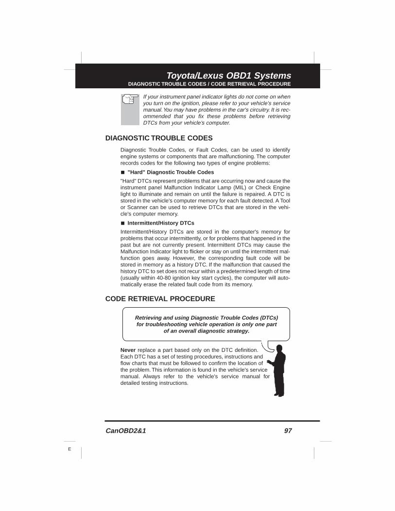
CanOBD2&1 97
E
Toyota/Lexus OBD1 SystemsDIAGNOSTIC TROUBLE CODES / CODE RETRIEVAL PROCEDURE
If your instrument panel indicator lights do not come on whenyou turn on the ignition, please refer to your vehicle's servicemanual.You may have problems in the car's circuitry. It is rec-ommended that you fix these problems before retrievingDTCs from your vehicle’s computer.
DIAGNOSTIC TROUBLE CODES
Diagnostic Trouble Codes, or Fault Codes, can be used to identifyengine systems or components that are malfunctioning. The computerrecords codes for the following two types of engine problems:
■ "Hard" Diagnostic Trouble Codes
"Hard" DTCs represent problems that are occurring now and cause theinstrument panel Malfunction Indicator Lamp (MIL) or Check Enginelight to illuminate and remain on until the failure is repaired. A DTC isstored in the vehicle's computer memory for each fault detected. A Toolor Scanner can be used to retrieve DTCs that are stored in the vehi-cle's computer memory.
■ Intermittent/History DTCs
Intermittent/History DTCs are stored in the computer's memory forproblems that occur intermittently, or for problems that happened in thepast but are not currently present. Intermittent DTCs may cause theMalfunction Indicator light to flicker or stay on until the intermittent mal-function goes away. However, the corresponding fault code will bestored in memory as a history DTC. If the malfunction that caused thehistory DTC to set does not recur within a predetermined length of time(usually within 40-80 ignition key start cycles), the computer will auto-matically erase the related fault code from its memory.
CODE RETRIEVAL PROCEDURE
Never replace a part based only on the DTC definition.Each DTC has a set of testing procedures, instructions andflow charts that must be followed to confirm the location ofthe problem. This information is found in the vehicle's servicemanual. Always refer to the vehicle's service manual fordetailed testing instructions.
Retrieving and using Diagnostic Trouble Codes (DTCs) for troubleshooting vehicle operation is only one part
of an overall diagnostic strategy.
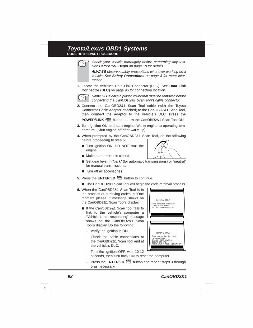
98 CanOBD2&1
E
Toyota/Lexus OBD1 SystemsCODE RETRIEVAL PROCEDURE
Check your vehicle thoroughly before performing any test.See Before You Begin on page 18 for details.
ALWAYS observe safety precautions whenever working on avehicle. See Safety Precautions on page 3 for more infor-mation.
1. Locate the vehicle's Data Link Connector (DLC). See Data LinkConnector (DLC) on page 96 for connection location.
Some DLCs have a plastic cover that must be removed beforeconnecting the CanOBD2&1 Scan Tool's cable connector.
2. Connect the CanOBD2&1 Scan Tool cable (with the ToyotaConnector Cable Adaptor attached) to the CanOBD2&1 Scan Tool,then connect the adaptor to the vehicle’s DLC. Press the
POWER/LINK button to turn the CanOBD2&1 Scan Tool ON.
3. Turn ignition ON and start engine. Warm engine to operating tem-perature. (Shut engine off after warm up).
4. When prompted by the CanOBD2&1 Scan Tool, do the followingbefore proceeding to step 5:
■ Turn ignition ON. DO NOT start theengine.
■ Make sure throttle is closed.
■ Set gear lever in "park" (for automatic transmissions) or “neutral”for manual transmissions.
■ Turn off all accessories.
5. Press the ENTER/LD button to continue.
■ The CanOBD2&1 Scan Tool will begin the code retrieval process.
6. When the CanOBD2&1 Scan Tool is inthe process of retrieving codes, a "Onemoment please..." message shows onthe CanOBD2&1 Scan Tool’s display.
■ If the CanOBD2&1 Scan Tool fails tolink to the vehicle’s computer a“Vehicle is not responding” messageshows on the CanOBD2&1 ScanTool’s display. Do the following:
- Verify the ignition is ON.
- Check the cable connections atthe CanOBD2&1 Scan Tool and atthe vehicle’s DLC.
- Turn the ignition OFF, wait 10-12seconds, then turn back ON to reset the computer.
- Press the ENTER/LD button and repeat steps 3 through5 as necessary.
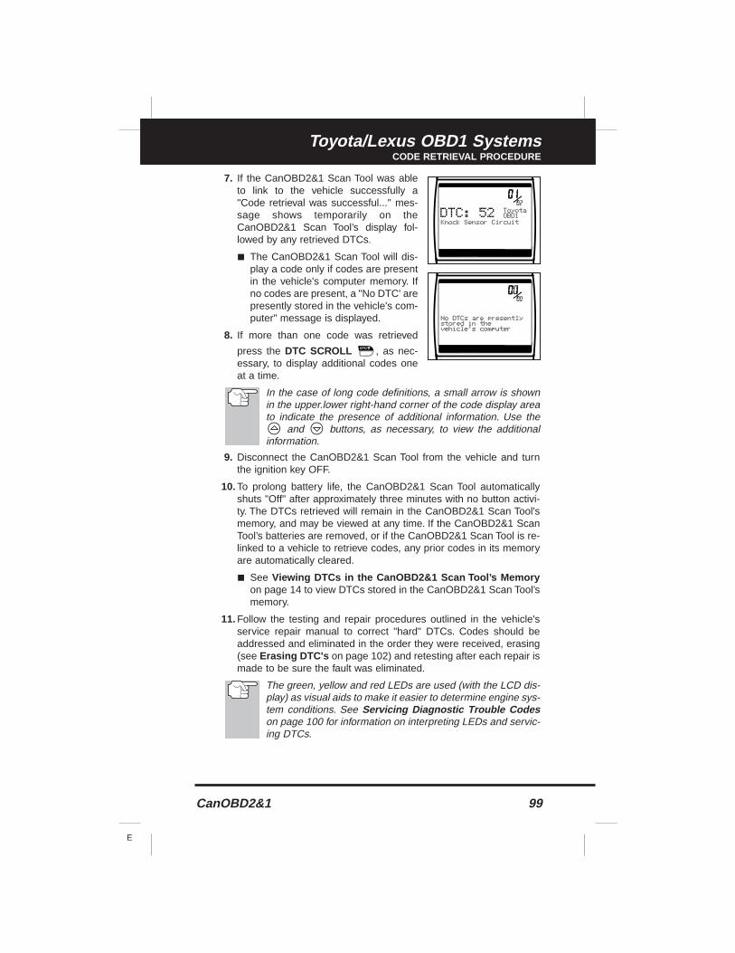
CanOBD2&1 99
E
Toyota/Lexus OBD1 SystemsCODE RETRIEVAL PROCEDURE
7. If the CanOBD2&1 Scan Tool was ableto link to the vehicle successfully a"Code retrieval was successful..." mes-sage shows temporarily on theCanOBD2&1 Scan Tool’s display fol-lowed by any retrieved DTCs.
■ The CanOBD2&1 Scan Tool will dis-play a code only if codes are presentin the vehicle's computer memory. Ifno codes are present, a "No DTC' arepresently stored in the vehicle's com-puter" message is displayed.
8. If more than one code was retrieved
press the DTC SCROLL , as nec-essary, to display additional codes oneat a time.
In the case of long code definitions, a small arrow is shownin the upper.lower right-hand corner of the code display areato indicate the presence of additional information. Use the
and buttons, as necessary, to view the additionalinformation.
9. Disconnect the CanOBD2&1 Scan Tool from the vehicle and turnthe ignition key OFF.
10. To prolong battery life, the CanOBD2&1 Scan Tool automaticallyshuts "Off" after approximately three minutes with no button activi-ty. The DTCs retrieved will remain in the CanOBD2&1 Scan Tool'smemory, and may be viewed at any time. If the CanOBD2&1 ScanTool’s batteries are removed, or if the CanOBD2&1 Scan Tool is re-linked to a vehicle to retrieve codes, any prior codes in its memoryare automatically cleared.
■ See Viewing DTCs in the CanOBD2&1 Scan Tool’s Memoryon page 14 to view DTCs stored in the CanOBD2&1 Scan Tool’smemory.
11. Follow the testing and repair procedures outlined in the vehicle'sservice repair manual to correct "hard" DTCs. Codes should beaddressed and eliminated in the order they were received, erasing(see Erasing DTC's on page 102) and retesting after each repair ismade to be sure the fault was eliminated.
The green, yellow and red LEDs are used (with the LCD dis-play) as visual aids to make it easier to determine engine sys-tem conditions. See Servicing Diagnostic Trouble Codeson page 100 for information on interpreting LEDs and servic-ing DTCs.
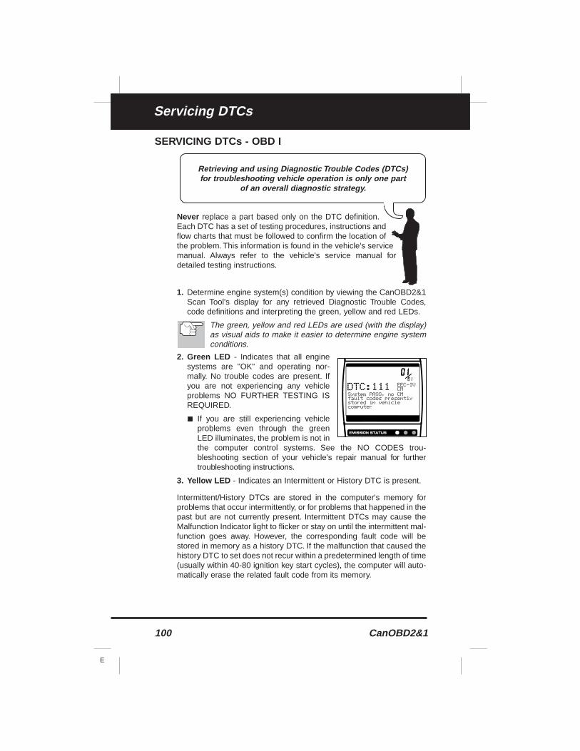
100 CanOBD2&1
E
Servicing DTCs
SERVICING DTCs - OBD I
Never replace a part based only on the DTC definition.Each DTC has a set of testing procedures, instructions andflow charts that must be followed to confirm the location ofthe problem. This information is found in the vehicle's servicemanual. Always refer to the vehicle's service manual fordetailed testing instructions.
1. Determine engine system(s) condition by viewing the CanOBD2&1Scan Tool's display for any retrieved Diagnostic Trouble Codes,code definitions and interpreting the green, yellow and red LEDs.
The green, yellow and red LEDs are used (with the display)as visual aids to make it easier to determine engine systemconditions.
2. Green LED - Indicates that all enginesystems are "OK" and operating nor-mally. No trouble codes are present. Ifyou are not experiencing any vehicleproblems NO FURTHER TESTING ISREQUIRED.
■ If you are still experiencing vehicleproblems even through the greenLED illuminates, the problem is not inthe computer control systems. See the NO CODES trou-bleshooting section of your vehicle's repair manual for furthertroubleshooting instructions.
3. Yellow LED - Indicates an Intermittent or History DTC is present.
Intermittent/History DTCs are stored in the computer's memory forproblems that occur intermittently, or for problems that happened in thepast but are not currently present. Intermittent DTCs may cause theMalfunction Indicator light to flicker or stay on until the intermittent mal-function goes away. However, the corresponding fault code will bestored in memory as a history DTC. If the malfunction that caused thehistory DTC to set does not recur within a predetermined length of time(usually within 40-80 ignition key start cycles), the computer will auto-matically erase the related fault code from its memory.
Retrieving and using Diagnostic Trouble Codes (DTCs) for troubleshooting vehicle operation is only one part
of an overall diagnostic strategy.
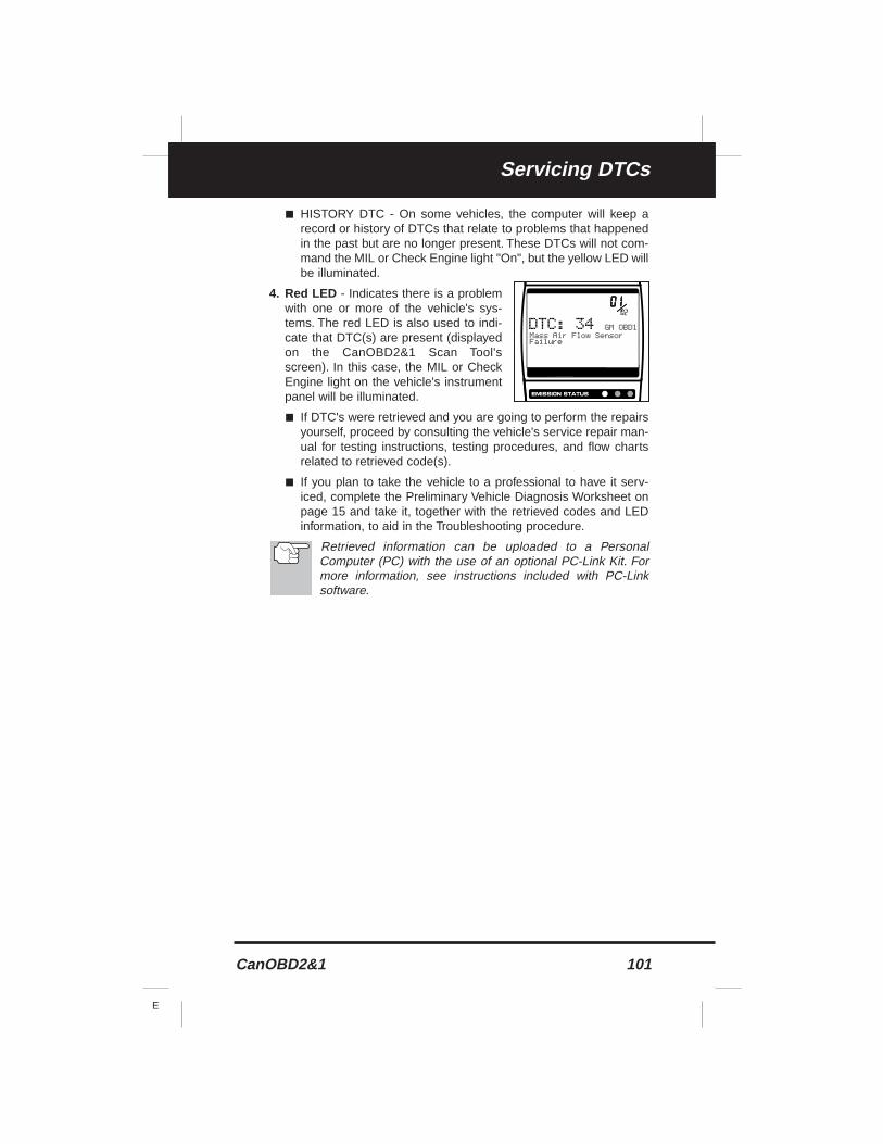
CanOBD2&1 101
E
Servicing DTCs
■ HISTORY DTC - On some vehicles, the computer will keep arecord or history of DTCs that relate to problems that happenedin the past but are no longer present. These DTCs will not com-mand the MIL or Check Engine light "On", but the yellow LED willbe illuminated.
4. Red LED - Indicates there is a problemwith one or more of the vehicle's sys-tems. The red LED is also used to indi-cate that DTC(s) are present (displayedon the CanOBD2&1 Scan Tool'sscreen). In this case, the MIL or CheckEngine light on the vehicle's instrumentpanel will be illuminated.
■ If DTC's were retrieved and you are going to perform the repairsyourself, proceed by consulting the vehicle's service repair man-ual for testing instructions, testing procedures, and flow chartsrelated to retrieved code(s).
■ If you plan to take the vehicle to a professional to have it serv-iced, complete the Preliminary Vehicle Diagnosis Worksheet onpage 15 and take it, together with the retrieved codes and LEDinformation, to aid in the Troubleshooting procedure.
Retrieved information can be uploaded to a PersonalComputer (PC) with the use of an optional PC-Link Kit. Formore information, see instructions included with PC-Linksoftware.
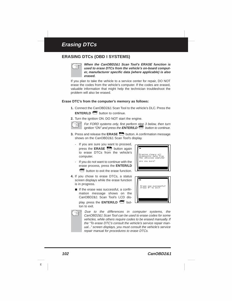
102 CanOBD2&1
E
Erasing DTCs
ERASING DTCs (OBD I SYSTEMS)
When the CanOBD2&1 Scan Tool's ERASE function isused to erase DTCs from the vehicle's on-board comput-er, manufacturer specific data (where applicable) is alsoerased.
If you plan to take the vehicle to a service center for repair, DO NOTerase the codes from the vehicle's computer. If the codes are erased,valuable information that might help the technician troubleshoot theproblem will also be erased.
Erase DTC’s from the computer’s memory as follows:
1. Connect the CanOBD2&1 Scan Tool to the vehicle’s DLC. Press the
ENTER/LD button to continue.
2. Turn the ignition ON. DO NOT start the engine.
For FORD systems only, first perform step 3 below, then turnignition “ON” and press the ENTER/LD button to continue.
3. Press and release the ERASE button. A confirmation messageshows on the CanOBD2&1 Scan Tool’s display.
- If you are sure you want to proceed,press the ERASE button againto erase DTCs from the vehicle'scomputer.
- If you do not want to continue with theerase process, press the ENTER/LD
button to exit the erase function.
4. If you chose to erase DTCs, a statusscreen displays while the erase functionis in progress.
■ If the erase was successful, a confir-mation message shows on theCanOBD2&1 Scan Tool’s LCD dis-
play. press the ENTER/LD but-ton to exit.
Due to the differences in computer systems, theCanOBD2&1 Scan Tool can be used to erase codes for somevehicles, while others require codes to be erased manually. Ifthe “To erase DTC’s consult the vehicle’s service repair man-ual...” screen displays, you must consult the vehicle’s servicerepair manual for procedures to erase DTCs.
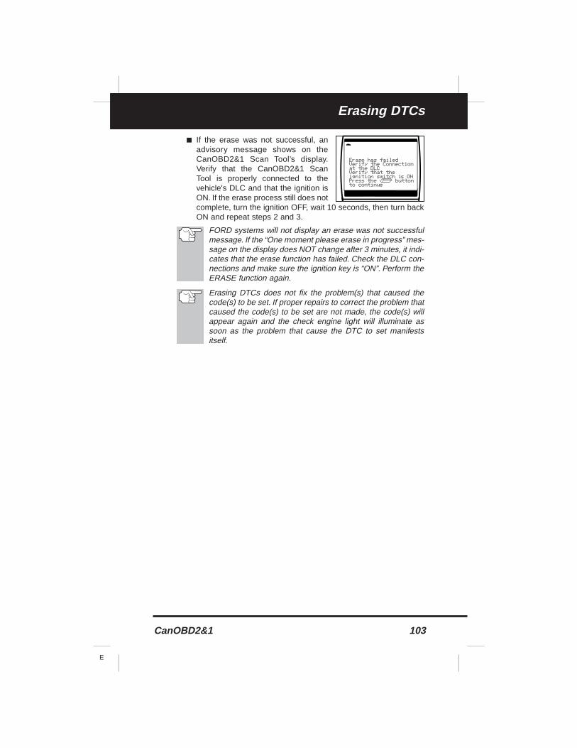
CanOBD2&1 103
E
Erasing DTCs
■ If the erase was not successful, anadvisory message shows on theCanOBD2&1 Scan Tool’s display.Verify that the CanOBD2&1 ScanTool is properly connected to thevehicle's DLC and that the ignition isON. If the erase process still does notcomplete, turn the ignition OFF, wait 10 seconds, then turn backON and repeat steps 2 and 3.
FORD systems will not display an erase was not successfulmessage. If the “One moment please erase in progress” mes-sage on the display does NOT change after 3 minutes, it indi-cates that the erase function has failed. Check the DLC con-nections and make sure the ignition key is “ON”. Perform theERASE function again.
Erasing DTCs does not fix the problem(s) that caused thecode(s) to be set. If proper repairs to correct the problem thatcaused the code(s) to be set are not made, the code(s) willappear again and the check engine light will illuminate assoon as the problem that cause the DTC to set manifestsitself.
104 CanOBD2&1
E
GlossaryGLOSSARY OF TERMS AND ABBREVIATIONS
GLOSSARY OF TERMS AND ABBREVIATIONS
CARB – California Air Resources Board
CCM – Central Control Module
Computer Control System – An electronic control system, consistingof an on-board computer and related sensors, switches and actuators,used to ensure peak performance and fuel efficiency while reducingpollutants in the vehicle’s emissions.
DIY – Do-It-Yourself
DLC – Data Link Connector
Drive Cycle – An extended set of driving procedures that takes intoconsideration the various types of driving conditions encountered inreal life.
Driving Condition – A specific environmental or operation conditionunder which a vehicle is operated; such as starting the vehicle whencold, driving at steady speed (cruising), accelerating, etc.
DTC(s) – Diagnostic Trouble Code(s)
EGR – Exhaust Gas Recirculation
EPA – Environmental Protection Agency
EVAP – Evaporative Emissions System
Fault Code – See DTCs
Freeze Frame – A digital representation of engine and/or emissionssystem conditions present when a fault code was recorded.
FTP – Fuel Tank Pressure
Generic Code – A DTC that applies to all OBD 2 compliant vehicles.
I/M Readiness – An indication of whether or not a vehicle’s emissions-related system are operating properly and are ready for Inspection andMaintenance testing.
I/M Test / Emissions Test / Smog Check – A functional test of a vehi-cle to determine if tailpipe emissions are within Federal/State/Localrequirements.
LCD – Liquid Crystal Display
LED – Light Emitting Diode
LTFT – Long Term Fuel Trim, is a program in the vehicle’s computerdesigned to add or subtract fuel from the vehicle to compensate foroperating conditions that vary from the ideal A/F ratio (long term).
Manufacturer Specific Code – A DTC that applies only to OBD 2compliant vehicles made by a specific manufacturer.
MIL – Malfunction Indicator Lamp (also referred to as “Check Engine”light
OBD 1 – On-Board Diagnostics Version 1 (also referred to as “OBD I”)
CanOBD2&1 105
E
GlossaryGLOSSARY OF TERMS AND ABBREVIATIONS
OBD 2 – On-Board Diagnostics Version 2 (also referred to as “OBD II”)
On-Board Computer – The central processing unit in the vehicle’scomputer control system.
PCM – Powertrain Control Module
Pending Code – A code recorded on the “first trip” for a “two-trip”code. If the fault that caused the code to be set is not detected on thesecond trip, the code is automatically erased.
PID – Parameter Identification
STFT – Short Term Fuel Trim, is a program in the vehicle’s computerdesigned to add or subtract fuel from the vehicle to compensate foroperating conditions that vary from the ideal A/F ratio.The vehicle usesthis program to make minor fuel adjustments (fine tune) on a short-term basis.
Trip Drive Cycle – Vehicle operation that provides the necessary driv-ing condition to enable a vehicle Monitor to run and complete its diag-nostic testing.
VECI – Vehicle Emission Control Information Decal

Notes
106 CanOBD2&1
E

Notes
CanOBD2&1 107
E

Notes
108 CanOBD2&1
E
Warranty and Servicing
CanOBD2&1 109
E
LIMITED ONE YEAR WARRANTY
The Manufacturer warrants to the original purchaser that this unit isfree of defects in materials and workmanship under normal use andmaintenance for a period of one (1) year from the date of original pur-chase.
If the unit fails within the one (1) year period, it will be repaired orreplaced, at the Manufacturer’s option, at no charge, when returnedprepaid to the Service Center with Proof of Purchase. The salesreceipt may be used for this purpose. Installation labor is not coveredunder this warranty. All replacement parts, whether new or remanufac-tured, assume as their warranty period only the remaining time of thiswarranty.
This warranty does not apply to damage caused by improper use, acci-dent, abuse, improper voltage, service, fire, flood, lightning, or otheracts of God, or if the product was altered or repaired by anyone otherthan the Manufacturer’s Service Center.
The Manufacturer, under no circumstances shall be liable for any con-sequential damages for breach of any written warranty of this unit. Thiswarranty gives you specific legal rights, and you may also have rights,which vary from state to state.This manual is copyrighted with all rightsreserved. No portion of this document may be copied or reproduced byany means without the express written permission of the Manufacturer.THIS WARRANTY IS NOT TRANSFERABLE. For service, send viaU.P.S. (if possible) prepaid to Manufacturer. Allow 3-4 weeks for serv-ice/repair.
SERVICE PROCEDURES
If you have any questions, require technical support or information onUPDATES and OPTIONAL ACCESSORIES, please contact your localstore, distributor or the Service Center.
USA & Canada:
(800) 544-4124 (6:00 AM-6:00 PM, Monday-Friday PST)
All others: (714) 241-6802 (6:00 AM-6:00 PM, Monday-Friday PST)
FAX: (714) 432-7511 (24 hr.)
www.CanOBD2.com
E
Innova Electronics Corp.17291 Mt. Herrmann StreetFountain Valley, CA 92708Printed in Taiwan
Instruction MRP
© 2006 Innova Electronics Corp. All rights reserved
#93-0197
PRODUCT DESIGN & COPYRIGHT
© 2006
®