Embed Size (px)
Citation preview
J. Electroanal. Chem., 126 (1981) 121-129 121 Elsevier Sequoia S.A., Lausanne--Printed in The Netherlands
THE DOUBLE LAYER AT THE INTERFACE BETWEEN TWO IMMISCIBLE ELECTROLYTE SOLUTIONS
PART I. CAPACITY. OF THE WATER/NITROBENZENE INTERFACE
Z. SAMEC, V. MARECEK and D. HOMOLKA
J. Heyrovskf, Institute of Physical" Chemistry and Electrochemistry, Czechoslovak Academy of Sciences, U tovtren 254, 102 O0 Prague 10 (Czechoslovakia)
(Received 9th March 1981)
ABSTRACT
From ac impedance measurements the capacity of the water/nitrobenzene interface was evaluated as a function of the potential difference between two phases in contact. In each phase an electrolyte was dissolved: LiC1 in water and tetrabutylammonium tetraphenylborate in nitrobenzene. The experimental results were interpreted in terms of the compound double-layer model in which the layer of the oriented solvent molecules (the inner or compact layer) separates two space-charge regions (diffuse double layer). The capacity of the diffuse double layer calculated using the Gouy-Chapman theory was found to fit well for the capacity of the interface. It was concluded that the potential drop across the inner compact layer remains constant and close to zero when the total potential drop across the interface is varied.
INTRODUCTION
The double layer at the interface between two immiscible electrolyte solutions (ITIES) has been the object of a few studies [1-8]. Much of work has also focused on the phenomena which are immediately associated with changes in the double layer structure at ITIES, such as electro-adsorption [9], electrical rectification [10] or mechano-electrical energy conversion [11,12] (for the complete list of references see ref. 13).
It has been suggested [2] that at ITIES the layer of the oriented molecules of both solvents (the inner or compact layer) separates two space-charge regions (the diffuse double layer). This model implies that for each phase the existence of the inner Helmholtz plane (x t or IHP) and of the outer Helmholtz plane (X 2 or OHP) can be postulated analogously to the model of the metal/solution interface [2].
The analysis of data from the surface tension measurements at the water/nitro- benzene interface led to the conclusion that the potential drop across the compact layer remains invariably very close to zero when the Galvani potential difference between the nitrobenzene and water phase is varied [3]. The whole potential drop across the interface concentrates in the diffuse double layer, the behaviour of which can be reasonably explained in terms of the classical Gouy-Chapman theory [2,3].
0022-0728/81/0000-0000/$02.50 © 1981 Elsevier Sequoia S.A.
122
In order to verify this important conclusion we examined the water/nitrobenzene interface by ac impedance measurements.
THEORETICAL
Capacity of the interface
Following the model considerations [2], the Galvani potential difference AW~q~ between two phases w and n in contact splits into the inner and the diffuse layer contributions:
Aw~ = ~(w) -- ~(n) = mwn~b i "J- ~b2(n ) -- ~b2(w ) (1)
where ~(w) and ~(n) are the electrical potentials in the bulk of w and n respectively, /~Wn~ i -~- t ~ ( X ~ ) - - ~ ( X ~ ) the potential drop across the inner layer and ~2(w) = ~(x'~) - ~(w) or ~2(n)= ~ ( x ~ ) - ~(n) the potential drops across the diffuse layers in the phase w or n respectively. The electroneutrality condition requires that
q(w) = - q ( n ) (2)
where q(w) and q(n) are the surface charge densities on the w- and n-side of the interface respectively.
If there is no ionic adsorption in the compact layer, the contribution of the inner and the diffuse layers to the capacity of the interface C = d q ( w ) / d A ~ can be uncoupled from each other [14]. Upon differentiating eqn. (1) with respect to the surface charge density q we obtain:
C- '=C: -1 +Cg_'w +cz_d (3)
where C i - - d q ( w ) / d A ~ i is the capacity of the inner layer and C2_ w = -dq(w)/d~2(w ) or C2_ n = - d q ( n ) / d ~ 2 ( n ) are the capacities of the diffuse layers in the phase w or n respectively.
Using the Gouy-Chapman theory for a symmetrical electrolyte the surface charge densities are [2]
q(n) = - 2A n sinh(zFq~2(n)/2RT ) (4)
q(w) = --2A w sinh(zFqJ2(w)/2RT ) (5)
and, consequently,
C2_ ~ = - aq(n)/O~2(n ) = (zFA~/RT) cosh(zFq~2(n)/2RT ) (6)
c2_w = - aq(w)/a 2(w) = (zeA /RT) cosh(zF%(w)/2RT) ( 7 )
where z is the ionic charge number and
A "(w) = (2 RTe"(W)c° )1/2 (8)
where e ~(w) is the dielectric constant.
123
Rs
crq
Zf
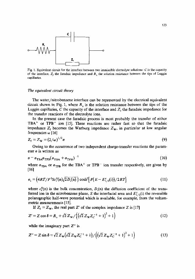
Fig. 1. Equivalent circuit for the interface between two immiscible electrolyte solutions: C is the capacity of the interface, Zf the faradaic impedance and R s the solution resistance between the tips of Luggin capillaries.
The equivalent circui t theory
The water/nitrobenzene interface can be represented by the electrical equivalent circuit shown in Fig. 1, where R s is the solution resistance between the tips of the Luggin capillaries, C the capacity of the interface and Zf the faradalc impedance for the transfer reactions of the electrolyte ions.
In the present case the faradaic process is most probably the transfer of either TBA + or TPB- ion [15]. These reactions are rather fast so that the faradaic impedance Zf becomes the Warburg impedance Z w, in particular at low angular frequencies to [16]
Z t = Z w = (2/to)l/2o (9)
Owing to the occurrence of two independent charge-transfer reactions the param- eter o is written as
o = OTBAO'TPB(OTB A + O'TPB) -1 (10)
where O~A or ORB for the TBA + or TPB- ion transfer respectively, are given by [161
e i = ( 4 R T / F 2 S c ° ( n ) ~ ) cosh2[ F(E-- E~/2(i))/2RT ] (11)
where c°(n) is the bulk concentration, Di(n ) the diffusion coefficient of the trans- ferred ion in the nitrobenzene phase, S the interfacial area and E(/2(i ) the reversible polarographic half-wave potential which is available, for example, from the voltam- metric measurements [15].
If Zf = Zw, the real part Z ' of the complex impedance Z is [17]
+ + l)
while the imaginary part Z" is
Z"= ZsinS=~/2Zw(qr2ZwZc' + 1)/((~/2ZwZc' + 1)2+ 1) (13)
124
where
zc
is the capacitance of the interface.
(14)
EXPERIMENTAL
The preparation of the aqueous solution of LiC1 and of the nitrobenzene solution of tetrabutylammonium tetraphenylborate (TBATPB) has been described previously [15]. They were brought into contact in an electrolytic cell [15] so that a water/nitrobenzene interface with a geometric area of 56 mm 2 was formed. The potential difference E~n of the galvanic cell:
AglAgCll c ° LiCI(H20)II c ° TBATPB(nb)I0.05 M TBACI(H20 ) IAgCllAg RE1 RE2
was controlled through the four-electrode potentiostat [15]. Similar experiments were carried out for the electrolyte concentrations c o = 0.01, 0.02, 0.05 or 0.1 M. The correct operation of the reference electrodes RE1 and RE2 was checked by the potentiometric measurement. The potential of RE2 (vs. SCE) was found to be 0.056 V and the potentials of RE1 (vs. SCE) were 0.099, 0.080, 0.056 or 0.046 V at the LiC1 concentrations 0.01, 0.02, 0.05 or 0.1 M.
The cell potential difference Ece n can be expressed by
Ecel l = AWn~ - - Aw~bOBA + "q- (2RT/F) ln(0.05/c °) + AE' (15)
where w 0 /~,4~TaA+ is the standard potential difference for TBA ÷ ion transfer and AE' is the term for the activity coefficients. The value of the latter was estimated using the Debye-Htickel expression as 1, 5, 10 or 16 mV for c o = 0.01, 0.02, 0.05 or 0.1 M respectively. The cell potential difference Ece n was corrected for the last two terms on the rhs of eqn. (15) so that the potential E in the following text is
E = Aw~ - Awq, OBA+ (16)
The impedance of the water/nitrobenzene interface was measured by ac polaro- graphic technique [16]. The small-amplitude (7.07 mV peak-to-peak) sinusoidal voltage signal from the 10 Hz to 100 kHz generator Tesla BM 524 (Czechoslovakia) was superposed on the slow triangular voltage pulse (5 mV s - l ) and fed to the four-electrode potentiostat. The positive feedback of the potentiostat was set to zero, i.e. the ohmic potential drop between the tips of the Luggin capillaries was not compensated.
The ac component of the output signal was decoupled from the dc component by the high-pass filter, compared with the input sinusoidal voltage signal in the phase-sensitive detector for the evaluation of the phase shift and finally rectified for the amplitude evaluation. The phase angle ~ and the effective amplitude Ief f of the sinusoidal current flowing through the interface were recorded on the X - Y recorder Aritma BAK 4T (Czechoslovakia).
125
The experiments were carried out with the air-saturated solutions at laboratory temperature, i.e. 22 ± 2°C.
RESULTS
The water/nitrobenzene interface was polarized in the potential range in which the TBA + or TPB- ion transfer reactions are barely detected by cyclic voltammetry, i.e. the faradaic impedance Z t is presumably much greater than the capacitance Z c.
If Z w >> Z c eqns. (12) and (13) become
Z ' = R s + ( 2 C 2 o ) - ' t o -3 /2 (17)
and
Z " = Z c -- ( t o G ) - ' (18)
respectively.
, uA
6 6(
4(
v E I I I I
- - - ~ A 4 ~
I I I I I I
0.50
OAO
0.30 I I
1.0 2.0 I I I 0.2 01.3 01.4 I
E/V r.,J-~/lO -3 rad-:F2 s3/2
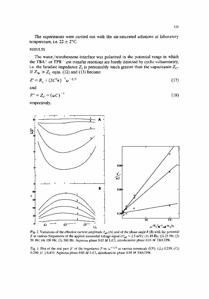
Fig. 2. Variations of the effective current amplitude Ieff (A) and of the phase angle 8 (B) with the potential E at various frequencies of the applied sinusoidal voltage signal (Vef ~ -- 2.5 mV): (l) l0 Hz; (2) 25 Hz; (3) 50 Hz; (4) 100 Hz; (5) 500 Hz. Aqueous phase 0.05 M LiC1, nitrobenzene phase 0.05 M TBATPB.
Fig. 3. Plot of the real part Z' of the impedance Z v s . co - 3 / 2 at various potentials E(V): (/x) 0.230; (O) 0.290; (D) 0.410. Aqueous phase 0.05 M LiC1, nitrobenzene phase 0.05 M TBATPB.
126
1.5
1.C ""
0.!
I I I 0.5 1.0 1.5
60-~/10- 2 rad - I s
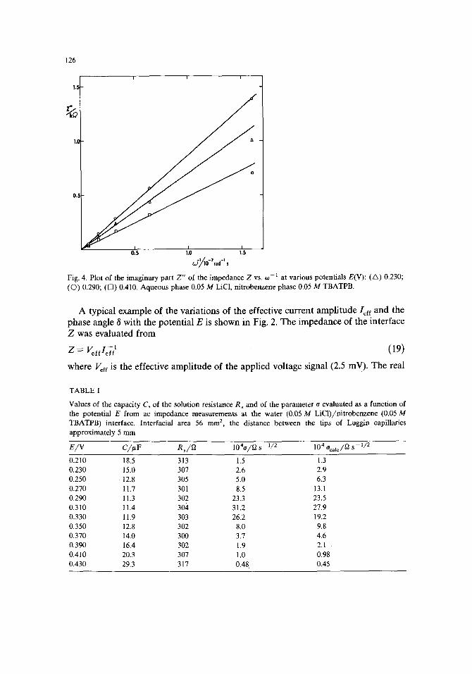
Fig. 4. Plot of the imaginary part Z" of the impedance Z vs. co i at various potentials E(V): (A) 0.230; (Q) 0.290; ([~) 0.410. Aqueous phase 0.05 M LiC1, nitrobenzene phase 0.05 M TBATPB.
A typical example of the variations of the effective current amplitude/eft and the phase angle ~ with the potential E is shown in Fig. 2. The impedance of the interface Z was evaluated from
Z : V~ffld/ (19)
where V~f e is the effective amplitude of the applied voltage signal (2.5 mV). The real
TABLE I
Values of the capacity C, of the solution resistance R S and of the parameter o evaluated as a function of the potential E from ac impedance measurements at the water (0.05 M LiC1)/nitrobenzene (0.05 M TBATPB) interface. Interracial area 56 mm 2, the distance between the tips of Luggin capillaries approximately 5 mm
E/V C/I~F Rs/~2 1040/~ s 112 104 Ocalc/~ s 1/2
0.210 18.5 313 1.5 1.3 0.230 15.0 307 2.6 2.9 0.250 12.8 305 5.0 6.3 0.270 11.7 301 8.5 13.1 0.290 11.3 302 23.3 23.5 0.310 11.4 304 31.2 27.9 0.330 11.9 303 26.2 19.2 0.350 12.8 302 8.0 9.8 0.370 14.0 300 3.7 4.6 0.390 16.4 302 1.9 2.1 0.410 20.3 307 1.0 0.98 0.430 29.3 317 0.48 0.45
127
par t Z ' = Z cos 8 was plot ted as a funct ion of OJ - 3 / 2 (Fig. 3) and the imaginary par t Z " = Z sin 8 was plot ted as a funct ion of 0: - l (Fig. 4). In agreement with eqns. (17) or (18) a linear relat ionship is observed in bo th cases. F r o m the slope of the plot of Z " vs. o~-~ the capaci ty C of the interface was calculated. The solution resistance R s was calculated by the ext rapola t ion of the plot of Z ' vs. o: -3/2 to 0:-3/2 = 0 and f rom the slope of this plot, d Z ' / d 0 a -3/2 - - ( 2 C 2 o ) - l, the pa rame te r o was found.
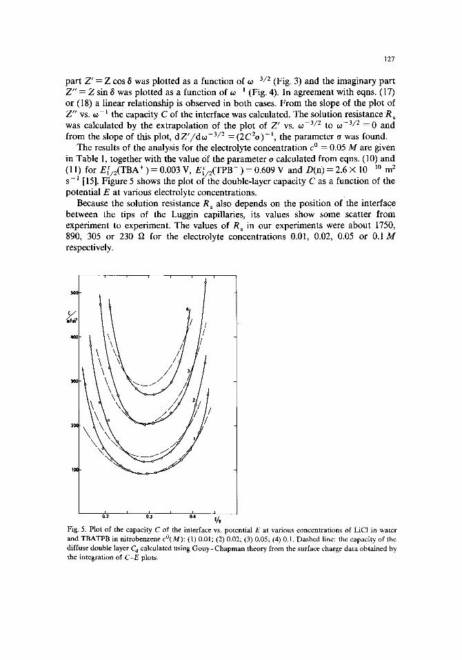
The results of the analysis for the electrolyte concentra t ion c o = 0.05 M are given in Table 1, together with the value of the pa rame te r o calculated f rom eqns. (10) and (11) for E[ /2(TBA + ) = 0.003 V, E [ / 2 ( T P B - ) = 0.609 V and D(n) = 2.6 × 10 -10 m 2 s -~ [15]. Figure 5 shows the plot of the double- layer capaci ty C as a funct ion of the potent ia l E at various electrolyte concentrat ions.
Because the solution resistance R s also depends on the posi t ion of the interface be tween the tips of the Luggin capillaries, its values show some scatter f rom exper iment to experiment . The values of Rs in our exper iments were abou t 1750, 890, 305 or 230 fa for the electrolyte concentra t ions 0.01, 0.02, 0.05 or 0.1 M respectively.
I 0.2 0.3 0.4 E//V
Fig. 5. Plot of the capacity C of the interface vs. potential E at various concentrations of LiCI in water and TBATPB in nitrobenzene c°(M): (1) 0.01; (2) 0.02; (3) 0.05; (4) 0.1. Dashed line: the capacity of the diffuse double layer C d calculated using Gouy-Chapman theory from the surface charge data obtained by the integration of C-E plots.
128
40
30
20
I0
0
-I(3
-20
-30
-40
I i
q l w / m C m "2
I
i I i
43
2 l
I I I l I I 0.2 0.3 0.4 E/V
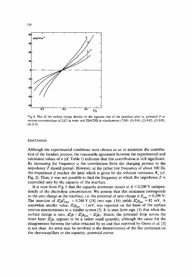
Fig. 6. Plot of the surface charge density on the aqueous side of the interface q(w) vs. potential E at various concentrations of LiCI in water and TBATPB in nitrobenzene c°(M): (1) 0.01; (2) 0.02; (3) 0.05; (4) 0.10.
DISCUSSION
Although the experimental conditions were chosen so as to minimize the contribu- tion of the faradaic process, the reasonable agreement between the experimental and calculated values of o (cf. Table 1) indicates that this contribution is still significant. By increasing the frequency co the contribution from the charging process to the impedance Z should prevail. However, at the rather low frequency of about 500 Hz the impedance Z reaches the limit which is given by the solution resistance R S (cf. Fig. 2). Thus, it was not possible to find the frequency at which the impedance Z is controlled only by the capacity of the interface.
It is seen from Fig. 5 that the capacity minimum occUrs at E -- 0.290 V indepen- dently of the electrolyte concentration. We assume that this minimum corresponds to the zero charge at the interface, i.e. the potential of zero charge is Epz c = 0.290 V. The insertion of w 0 w A'nt~TBA+ =0.248 V [18] into eqn. (16) yields /~n~bpzc-=-42 mV. A somewhat smaller value, mW~pzc = 1 mV, was reported on the basis of the surface tension measurements in a similar system [3]. It is seen from eqn. (1) that when the surface charge is zero, Aw~ = AW~pzc = Aw~i. Hence, the potential drop across the inner layer Awq~ i appears to be a rather small quantity, although the cause for the disagreement between the value obtained by us and that reported by Gross et al. [3] is not clear. An error may be involved in the determination of the flat extremum on the electrocapillary or the capacity-potential curves.
129
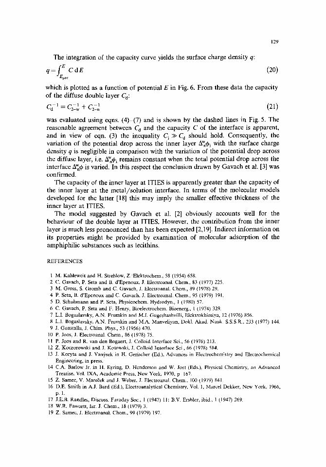
The integration of the capacity curve yields the surface charge density q:
_re CdE (20) q-- epzc
which is plotted as a function of potential E in Fig. 6. From these data the capacity of the diffuse double layer Ca:
-1 = + c2_-2 ( 2 1 )
was evaluated using eqns. (4)-(7) and is shown by the dashed lines in Fig. 5. The reasonable agreement between C a and the capacity C of the interface is apparent, and in view of eqn. (3) the inequality C i >> C d should hold. Consequently, the variation of the potential drop across the inner layer AW~i with the surface charge density q is negligible in comparison with the variation of the potential drop across the diffuse layer, i.e. A'~ i remains constant when the total potential drop across the interface AW~q~ is varied. In this respect the conclusion drawn by Gavach et al. [3] was confirmed.
The capacity of the inner layer at ITIES is apparently greater than the capacity of the inner layer at the metal/solution interface. In terms of the molecular models developed for the latter [18] this may imply the smaller effective thickness of the inner layer at ITIES.
The model suggested by Gavach et al. [2] obviously accounts well for the behaviour of the double layer at ITIES. However, the contribution from the inner layer is much less pronounced than has been expected [2,19]. Indirect information on its properties might be provided by examination of molecular adsorption of the amphiphilic substances such as lecithins.
REFERENCES
1 M. Kahleweit and H. Strehlow, Z.'Elektrochem., 58 (1954) 658. 2 C. Gavach, P. Seta and B. d'Epenoux, J. Electroanal. Chem., 83 (1977) 225. 3 M. Gross, S. Gromb and C. Gavach, J. Electroanal. Chem., 89 (1978) 29. 4 P. Seta, B. d'Epenoux and C. Gavach, J. Electroanal. Chem., 95 (1979) 191. 5 D. Schuhmann and P. Seta, Physicochem. Hydrodyn., 1 (1980) 57. 6 C. Gavach, P. Seta and F. Henry, Bioelectrochem. Bioenerg., 1 (1974) 329. 7 L.I. Boguslavsky, A.N. Frumkin and M.I. Gugeshashvilli, Elektrokhimiya, 12 (1976) 856. 8 L.I. Boguslavsky, A.N. Frumkin and M.A. Manveliyan, Dokl. Akad. Nauk. S.S.S.R., 233 (1977) 144. 9 J. Guastalla, J. Chim. Phys., 53 (1956) 470.
10 P. Joos, J. Electroanal. Chem., 86 (1978) 75. 11 P. Joos and R. van den Bogaert, J. Colloid Interface Sci., 56 (1976) 213. 12 Z. Koczorowski and J. Kotowski, J. Colloid Interface Sci., 66 (1978) 584. 13 J. Koryta and J. Van2;,sek in H. Gerischer (Ed.), Advances in Electrochemistry and Electrochemical
Engineering, in press. 14 C.A. Barlow Jr. in H. Eyring, D. Henderson and W. Jost (Eds.), Physical Chemistry, an Advanced
Treatise, Vol. IXA, Academic Press, New York, 1970, p. 167. 15 Z. Samec, V. Mare~ek and J. Weber, J. Electroanal. Chem., 100 (1979) 841. 16 D.E. Smith in A.J. Bard (Ed.), Electroanalytical Chemistry, Vol. 1, Marcel Dekker, New York, 1966,
p. 1. 17 J.E.B. Randles, Discuss. Faraday Soc., 1 (1947) 11; B.V. Ershler, ibid., 1 (1947) 269. 18 W.R. Fawcett, Isr. J. Chem., 18 (1979) 3. 19 Z. Samec, J. Electroanal. Chem., 99 (1979) 197.