Embed Size (px)
Citation preview
The Directed Reverse Path Join (DRPJ) Protocol: An Efficient
Multicast Routing Protocol
Hiroshi Fujinoki Kenneth J. Christensen (*** correspondence author ***)
Department of Computer Science and Engineering 4202 East Fowler Avenue, ENB 118
University of South Florida Tampa, Florida 33620
Phone: 813 974-4761 FAX: 813 974-5456
Email: {fujihir, christen}@csee.usf.edu
Abstract The new Directed Reverse Path Join (DRPJ) protocol efficiently implements a Greedy routing algorithm for generating a multicast tree. The DRPJ protocol minimizes the messaging overhead from probe messages and allows a joining node to find multiple paths that are not constrained to be only the shortest paths. This enables a controllable tradeoff between path length and bandwidth consumption. Using simulation, the DRPJ protocol is compared to the existing Flooding with TTL and Directed Spanning Join (DSJ) protocols. Using a topology model of the current Internet, it is found that the DRPJ protocol reduces probe messages by nearly 90% and 75% when compared to the Flooding with TTL and DSJ protocols, respectively.
Key Words Multicast, multicast routing protocols, dynamic membership
1
1. Introduction
Multicasting is a selective one-to-many broadcast mechanism used by a growing number of applications
including video on demand and file distribution. The primary advantage of multicasting is that only a single
transmission is necessary for sending the same information to n receivers, while n independent transmissions would
be required using one-to-one unicasting. To take full advantage of the 1/n bandwidth consumption property, it is
important to find paths that are shared by receivers. A multicast session entails a collection of paths with the
multicast sender as its root, forming a multicast tree. In a multicast tree, group members are a subset of all the nodes
in the network. Assuming that multicast membership is dynamic, meaning that each receiver can join and leave a
multicast session at any time, multicast routing is needed to find the best path from a joining receiver node to one of
the receiver nodes (or directly to the sender). Thus, a node joining a multicast session needs to be connected to an
existing node, called a multicast neighbor node. Each receiver initiates the neighbor search whenever it wants to join
a multicast session.
If a multicast tree is created based on a shortest path tree, multicast routing is reduced to the simple problem of
finding the nearest multicast neighbor node on the shortest path from a joining node. A routing protocol is a set of
rules to collect and exchange information necessary for a routing algorithm to make routing decisions [8]. However,
if a shortest path is chosen without regard to existing paths, the bandwidth reduction advantage of multicast is
reduced. An algorithm that solves this problem is the Shortest Best Path Tree (SBPT) algorithm [18]. The SBPT
algorithm reduces bandwidth consumption by choosing, from a set of shortest paths, one that already contains
receivers and, hence, is a partially completed path. Choosing such a partially completed shortest path can save over
10% in bandwidth consumption [18]. For delay-insensitive applications, we could further increase the possibility of
reducing bandwidth consumption by including non-shortest paths. There is a tradeoff relationship between path
length and bandwidth consumption [13, 19, 24, 33]. The two extremes correspond to the Shortest Path Tree (SPT)
[11] and the Greedy algorithm [32]. In [19], we proposed the Path Length Control (PLC) algorithm that can trade-
off path length and bandwidth consumption for a given delay requirement. In both the SBPT and PLC algorithms,
each joining node determines its path to the target multicast tree if the multicast tree already exists.
Routing in the current Internet consists of two components: inter-AS (inter-domain) routing and intra-AS (intra-
domain) routing where an autonomous system (AS) is a computer network managed by a single organization. Inter-
2
domain routing determines paths between ASes. For intra-domain routing, distance-vector and link-state protocols
are used. Distance vector protocols have small messaging overhead, and are distributed, but have slow propagation
of routing information. In a link-state protocol [25], any changes for a link will be broadcast to all other routers in
the network. The propagation of the routing information takes less time than a distance-vector routing, resulting in
more accurate routing information. Each router has topology information for the entire network, which allows for
efficient policy-based routing [14, 34]. However, since link state updates are broadcast for each change in link state
there exists a trade-off relationship between quality of routing and messaging overhead [8, 30, 34]. Due to the large
messaging and storage overhead under these conditions, link-state routing protocols are generally not adequate for an
inter-domain routing protocol in its pure form [14, 15]. Distance-vector routing is used for an inter-domain routing
protocol, such as Exterior Gateway Protocol (EGP) [29] and Border Gateway Protocol (BGP) [31].
One of the most significant problems in current multicast protocols is the large messaging overhead to find the
best multicast neighbor. This is essentially the same trade-off problem between link-state routing and distance-
vector routing protocols. This high messaging overhead becomes an especially serious problem if multicast
membership changes dynamically [33]. In this paper, a new distributed routing protocol that finds multiple paths for
a dynamic membership is proposed and evaluated. The new protocol generates significantly less messaging
overhead than existing protocols. Messaging overhead is reduced by allowing each receiver to specify how broad
the area of multiple-path search should be, depending on its end-to-end delay requirement.
The remainder of this paper is organized as follows. In Section2 the overhead of flooding protocols is
quantified. Section2, also presents key definitions and assumptions. In Section3, existing work in multicast routing
is reviewed focusing on the Flooding with TTL [11] and Distributed Spanning Join (DSJ) [5] protocols. In Section4,
the new Directed Reverse Path Join (DRPJ) protocol is described and analyzed for its messaging overhead and cost
of execution. Section5 contains a simulation comparison of the DRPJ protocol with the Flooding with TTL and DSJ
protocols. Section6 is a summary followed by a list of references.
2. The Flooding Problem in Multicast Routing Protocols
3
The simplest protocol for finding multiple paths for a multicast tree is by unbounded flooding of probe
messages. In unbounded flooding, a node forwards all new probe messages, and previously forwarded probe
messages are discarded. The multicast sender does not forward probe messages. Pseudocode for unbounded
flooding is shown in Figure 1. The key fields of the probe message are:
• Sender ID ( IDS )
• Joining node ID ( IDJ )
• Multicast session ID ( IDM )
Group membership is assumed to be specified via channel address [23]. In channel addressing, multicast group
membership is specified by a combination of the sender ID and the member group ID. The term “multicast session
ID” is used instead of “channel destination addresses”. To distinguish the current join request from previous
requests, a unique sequence number field is required. As a probe message traverses a network, it records each
intermediate node on its path. When a probe message reaches one of the multicast neighbor nodes (or the sender),
flooding of the probe message is stopped and the list of the propagated intermediate nodes is returned directly to the
joining node. From this reply message, the joining node determines the path to one of the multicast neighbors.
Unbounded flooding is entirely infeasible due to the very high probe message overhead.
In this paper, a hierarchical topology model is used to evaluate the multicast routing protocols. A hierarchical
topology model, called a transit-stub model, is proposed as a network topology to model the Internet domain
structure by Calvert et al. [6, 7]. This corresponds to the structure of the current Internet where the edge networks
correspond to ASes [31]. In this topology model, a packet switched network is comprised of edge networks and a
backbone. The key concept is that for each layer in the hierarchy a different routing protocol is used. For actual
implementation, the MBGP/PIM-SM/MSDP architecture [16] is introduced for IP Multicasting [2]. The Multicast
Border Gateway Protocol (MBGP) is an inter-domain multicast routing protocol (it is responsible for routing in the
highest layer), while Protocol Independent Multicast-Sparse Mode (PIM-SM) is an intra-domain multicast routing
that performs routing information exchange in the second layer. The Multicast Source Discovery Protocol (MSDP)
is another inter-domain protocol that announces the existence of a multicast neighbor for a multicast session.
To estimate the significance of the messaging overhead in the Internet, we performed an evaluation of the
estimated number and bandwidth requirement of probe messages that the Internet must transport using the Flooding
4
with TTL protocol [11] (this protocol is described in Section 3.1). We chose the Flooding with TTL protocol,
instead of the unbounded flooding protocol, since the unbounded flooding protocol is not feasible for
implementation due to its high messaging overhead. The National Laboratory for Applied Network Research
(NLANR) reports 6,474 ASes with 13,895 AS interconnections as a result of their AS trace on January 2, 2000 (this
information is in ASConnlist20000102 [27]). The number of hosts in the Internet AS network is reported as
72,398,092 [9, 24] (for January 2000).
It was conservatively assumed that each host would join a multicast session once per month on average with the
following parameters:
• ASN Number of AS networks in the Internet ( ASN = 6,474 [27])
• LN Number of links in the AS network ( LN = 13,895 [27])
• HN Number of hosts in the Internet ( HN = 72,398,092 [9, 24])
• T Average time interval between two consecutive multicast session initiations at each joining host
(T = 2,592,000 seconds = 30 days)
The average number of hosts that will make a join request per second is simply HN divided by T , resulting in
approximately 28 hosts per second making a join request. To see how many probe messages will be generated in
existing routing protocols, simulation experiments were performed using an actual AS network reconstructed from
the AS connectivity information (ASconnpairs20000102.txt) [27]. Twenty-eight joining nodes and a sender for each
joining node were randomly chosen in each simulation run. In 100 simulation runs, the largest number of probes
received at an AS was 304,752 probes and this was observed at the AS with the largest number of links in the
network (i.e., AS-701, which is UUNET). The average of the maximum probes received at an AS for the 100
experiment runs was 58,134. This demonstrates a three to four orders of magnitude blow-up in message rate.
Assuming 128 bytes per probe message, 304,752 probe messages per second is 312 Mbps incoming to a router and
58,134 probe messages per second is 59.5 Mbps. This represents a very high processing overhead for a router. As
the number of multicast applications increases, this already prohibitive messaging overhead will increase causing
further probe message overflow and other problems at routers.
3. The Flooding with TTL and DSJ Protocols
5
Two existing protocols that arose from the inefficiency of unbounded flooding are the Flooding with TTL [11]
and Distributed Spanning Join (DSJ) protocols [5]. These two protocols implement a greedy and a core-based tree
approach. Other protocols include MOSPF [26], PIM [12], and DVMRP [10]. These protocols are all shortest-path
based multicast routing protocols. Our interest is not only in shortest paths, but also in bandwidth reduction. Thus,
we study the two major non shortest path protocols - Flooding with TTL and DSJ protocols. In the remainder of this
section we quantify the Flooding with TTL and DSJ protocol in terms of algorithm complexity cost and storage
overhead of probe messages. This quantification then motivates the new Distributed Reverse Path Join (DRPJ)
protocol.
3.1 The Flooding with TTL protocol
One way to reduce the overhead of unbounded flooding is by adding a Time-To-Live (TTL) scope. The
Flooding with TTL protocol [11] is exactly the same as unbounded flooding, except for the limitation enforced by
the TTL field in each probe message. The TTL field is set to some threshold value (usually the hop-count distance
to the sender is used) before the probe message is flooded. On each hop, the TTL field in the probe message is
decreased by one. When the TTL reaches zero, the probe message is dropped. In addition to the three fields used in
unbounded flooding ( IDJ , IDS , and IDM ), the Flooding with TTL protocol adds a TTLC field. By setting the TTL
scope to be the shortest distance between the joining node and the sender, probe messages will never be propagated
beyond the sender, thus limiting the number of probe messages. Figure 2 shows the area of probe messages
generated by the Flooding with TTL protocol.
Pseudocode for Flooding with TTL is shown in Figure 3. After an intermediate node receives a probe message
from a joining node, j, it determines if the intermediate node is already a part of the target multicast tree (line 2 in
Figure 3). A ( IDS , IDM ) pair is required for each multicast session available at an intermediate node. To determine
if the specified multicast session is available at an intermediate node, a linear search is required for a matching ( IDS ,
IDM ) pair in the local multicast routing table of the intermediate node. This procedure takes O(n) time, where n is
the average number of multicast sessions active at an intermediate node. All other steps in the algorithm take

6
constant time. Thus, the processing cost required at each intermediate node is in O(n). Since a probe message holds
the ID of every AS encountered on the way from a joining node to a sender, the size of the probe message is O(n),
where n is the number of ASes in the possible longest path from the joining node to the sender. Since each ( IDS ,
IDM ) pair corresponds to an active multicast session, the storage overhead of the local multicast routing table is
O(n) for an average of n multicast sessions active at an intermediate node at a given time.
3.2 The Directed Spanning Join (DSJ) protocol
Carlberg introduces the Directed Spanning Join (DSJ) multicast routing protocol [5] to further reduce the
number of probe messages required for finding paths from a joining node to its multicast neighbor nodes. The DSJ
protocol assumes a shared tree approach and that the sender is the root (or core) of a shared tree such as a Core
Based Tree (CBT) [3]. In a shared tree, a single multicast tree will be shared by all multicast sessions in the network.
In the DSJ protocol, a joining node broadcasts probe messages looking for a point of connection to a multicast tree.
The probe messages are broadcast along the shortest paths based on the Reverse Path Forwarding (RPF) protocol
[11]. In the RPF protocol when an intermediate node receives a probe message on one of its incoming ports, the
broadcast probe message will be dropped if the port is not the one on the shortest path from the node to the joining
node. Otherwise, the probe message will be sent out from all other ports. The term “Reverse Path” comes from the
fact that all probe messages exactly follow the shortest paths back from a joining node.
The probe message used in the DSJ protocol adds one new field over the Flooding with TTL protocol: the
METRICD field. This field is initialized to be the shortest distance between the joining node and the sender before it is
flooded. When an intermediate node receives a probe message, the intermediate node checks whether it is a
multicast neighbor node of the requested multicast tree. If it is, the protocol is terminated and the probe message is
dropped. If it is not, the intermediate node checks the port where the probe message is received. If the port is not
the designated port for the shortest path back to the joining node, the protocol is terminated. If it is the designated
port, the shortest distance from the intermediate node to the sender ( iD ) and the routing metric in the probe message
(i.e., the METRICD field) are compared. If METRICi DD ≤ , then iD will be assigned to METRICD and the probe message is
7
broadcast again using RPF. If METRICi DD > , the probe message will be dropped. The DSJ protocol is shown in
Figure 4.
The cost of the DSJ protocol at each intermediate node is in the order of O(n), where n is the average number
of multicast sessions active at an intermediate node at a given time. As can be seen in Figure 4, all the procedures,
except at line 2, take constant time. This is the same as in Flooding with TTL. Thus, the DSJ protocol takes O(n)
time at each intermediate node. Similar to Flooding with TTL, the size of the probe message is O(n), where n is the
number of ASes in the possible longest path from the joining node to the sender. The storage overhead for the local
multicast routing table in the DSJ protocol is O(n) where n is the average number of multicast sessions active.
There are situations where the DSJ protocol will not reduce a probe message overhead compared to Flooding
with TTL. This is because the DSJ protocol does not consider the final path length between the joining node and the
sender when it makes a decision whether an intermediate node should flood a probe message. Figure 5 shows this
potential problem where the value associated with each link is the distance in hop count. If a probe message is sent
from the joining node to an intermediate node v1 through v4, v3, and v2 (this path is one of the shortest paths from
the joining node to v1) then the resulting path length from the joining and sending nodes via v1 is unknown at v1. An
intermediate node cannot efficiently make a decision based on the final resulting path length between the joining
node and the sender. As a result, probe messages may be flooded to the intermediate nodes, unable to find
acceptable multiple paths. This problem becomes serious if the distance between a joining node and the sender is the
network diameter. In this case, the DSJ protocol will simply reduce to unbounded flooding.
The DSJ protocol assumes a shared tree approach. It has been argued that the most serious problem in a shared
tree approach is traffic congestion [33]. Traffic congestion occurs as a result of all multicast traffic having to share a
single common tree even when alternative paths exist with low utilization [12]. Since the location of the core affects
the performance, the optimal position of the core should be calculated for each possible multicast session. Thus, a
shared tree approach poses significant problems for delay sensitive applications because multicast applications do
not have control over selecting paths.
4. The Directed Reverse Path Join (DRPJ) Protocol
8
The goal of the DRPJ protocol is to have the capability for multiple path search without blindly flooding probe
messages. The multiple path search aims for the shortest paths as well as for non-shortest paths permitting a trade-
off of delay and bandwidth consumption. This is accomplished by:
• Reducing the number of probe messages by taking the final path length between the joining node and the
sender into consideration.
• Allowing joining nodes to adjust the area of a multiple path search depending on how strict are the end-to-
end delay requirements.
As described in Section 3, the DSJ protocol may fail to reduce probe message overhead in some cases. The DRPJ
protocol addresses these cases.
4.1 Description of the DRPJ protocol
The DRPJ protocol introduces the concept of Maximum Deviation in hop count ( MDD ). The MDD specifies
the maximum tolerable extra path length beyond the shortest path. The MDD field conveys a joining node’s end-to-
end delay requirement to all intermediate nodes receiving the probe message. If 0=MDD , only the shortest paths
will be searched If KDMD = , all the paths longer than the shortest paths up to K hops will be searched. Assuming
the shortest distance to every other node is known at each node in a network, the MDD field is set before a probe
message is emitted from a joining node as jsMD DCD ⋅= for 10 ≤≤ C and where jsD is the shortest distance from
a joining node, j, to the sender node, s. At each intermediate node, a decision is made regarding whether the probe
message should be further broadcast. Instead of having a dedicated field in the probe message, the hop count as
indicated by the MDD field is added to the TTLC field (this is explained later in more detail) to reduce the size of the
probe message.
The information included in the probe message for the DRPJ protocol is the same as the Flooding with TTL
protocol. The IDS field identifies the target sender and the IDM field identifies the multicast stream. This allows
multiple simultaneous multicast sessions at a single sender. The IDJ field identifies the joining node. The DRPJ
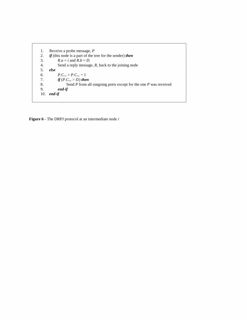
protocol is shown in Figure 6. Before the probe message is flooded from the joining node, the TTLC field is set as
9
MDjTTL DDC += where jD is the shortest distance from the joining node to the sender. On each hop, the TTLC
field is decreased by one. As a result, only the TTLC field is modified during the flooding of the probe message.
After a probe message arrives at an intermediate node, i, IDS and IDM in the probe message will be examined. An
intermediate node is a multicast neighbor node of the requested multicast tree if one conditions hold:
1) The node is currently an active receiver of the requested multicast session identified by the sender address
( IDS ) and session ID ( IDM ) pair.
2) The node is currently a part of a multicast tree for the requested multicast session.
It is possible for an intermediate node to be a multicast neighbor for multiple multicast sessions. There must be
a ( IDS , IDM ) pair in the local routing table as ( IDS , IDM , ifO , ifI ) for each multicast session active at an
intermediate node. The ifO field specifies the list of outgoing interfaces that indicate downstream child nodes for
that particular multicast session. The ifI field specifies the incoming interface that points to the parent node of the
multicast tree. If there is a matching ( IDS , IDM ) pair in the local routing table, then node i will send a reply
message back to the joining node. The reply message includes the following information: 1) ID (address) of node i,
2) TTLC field in the probe message, and 3) shortest distance, iD , between node i to the sender. The distance between
the joining node and node i can be calculated at the joining node as TTLMDj CDD −+ using the TTLC field returned
by node i. If there is a matching ( IDS , IDM ) pair, a reply message is returned to the joining node by the
intermediate node in order to announce its existence. If there exists no matching ( IDS , IDM ) pair, the reply message
will not be returned to the joining node. Note that the procedure (i.e., 1−= TTLTTL CC ) is performed only if there is
no matching ( IDS , IDM ) pair (i.e., this intermediate node is not a multicast neighbor). Thus, when the procedure
(i.e., 1−= TTLTTL CC ) is executed, a reply message will not be returned. After 1−= TTLTTL CC is performed, the TTLC
and iD fields will be compared. If iTTL DC < then the probe message is dropped. If iTTL DC ≥ then the probe
message will be flooded again from all the outgoing ports at node i, except for the one where the probe message was
received. The comparison between TTLC and iD ensures that a probe message will propagate further only if it is
within a maximum deviation from the shortest path specified by the joining node. Unlike the Flooding with TTL and
DSJ protocols, 0>TTLC does not have to be tested since iTTL DC ≥ implies 0>TTLC .
10
The DRPJ protocol assumes that the shortest distance to all other nodes in a network is stored at each
intermediate node. The DRPJ protocol can be implemented on top of an existing unicast shortest path protocol.
Link failures and link state updates can be handled by an underlying unicast routing protocol. In case of a link
failure, all the affected multicast receivers initiate the DRPJ again. When a link state is updated by an underlying
unicast shortest path protocol, the updated link state takes effect from the first join operation after the update.
The most significant difference between the DSJ and DRPJ protocols is that in the DRPJ protocol the length of
the resulting path from a joining node to the sender must be considered in order to make a decision whether a probe
message should be farther propagated or terminated. For example, if the distance from a joining node to the sender
is not considered in Figure 5, probe messages will be propagated to all intermediate nodes v1 through v8. Since
those intermediate nodes are more than one hop away from the joining node but have the same distance to the sender,
probe messages will be propagated to all of v1 through v8 in the DSJ protocol. This also implies that if the distance
between a joining node and a sender is the network diameter, this approach is simply a flooding approach. If probe
messages will be propagated on only those paths contributing to finding paths within the given delay bound (i.e., will
not flood probes to any other paths), such a multicast routing protocol should provide more flexibility and efficiency
in finding paths. The DRPJ protocol allows each multicast receiver to configure the delay upper bound by tuning
the MDD value when it searches for paths.
4.2 Complexity and storage overhead analysis for the DSJ and DRPJ protocols
The first task an intermediate node must perform is to determine whether it is a multicast neighbor of the
requested multicast session. To find a matching ( IDS , IDM ) pair in the local routing table (line 2 in Figure 6), a
linear search is required which is in the order of O(n) for an average of n multicast sessions active at an intermediate
node at a given time. All other operations require a constant time. Therefore, the DRPJ protocol has the worst case
complexity of O(n). Similar to the DSJ protocol, the size of the probe message is O(n), where n is the number of
ASes in the possible longest path from the joining node to the sender. Thus, the DRPJ protocol has the same order
for the size of the probe message as the DSJ protocol. The storage overhead of the local multicast routing table is in
11
O(n) for an average of n multicast sessions at an intermediate node at a given time. As a result, the DRPJ protocol
has the same worst-case procedure complexity and storage overhead as the DSJ protocol.
4.3 Probe message overhead for Flooding with TTL, DSJ and DRPJ protocols
The first five lines in the Flooding with TTL (Figure 3), DSJ (Figure 4) and DRPJ protocol (Figure 6) are the
same. Between the Flooding with TTL and DSJ protocols, the only difference is that the DSJ protocol enforces
another condition. If the METRICD field in a probe message is smaller than the distance from an intermediate node to
the sender, the probe message will be dropped at the intermediate node. Since the METRICD field is updated each time
it reaches an intermediate node with shorter distance to the sender, it limits the propagation of the probe messages.
Moreover, the probes will be broadcast along the shortest paths using the RPF (i.e., a router forwards messages from
a source only if they arrive via the shortest path back to the source). This is not enforced in the Flooding with TTL
protocol. Therefore, the number of probes in Flooding with TTL is at least the number of probes in the DSJ protocol.
In the DRPJ protocol if 0=MDD all the probe messages are propagated only on the shortest paths from a joining
node to a sender. It has been seen that the DSJ protocol propagates probes on the paths where the length from a
joining node to server is longer than the shortest distance. Thus, the number of probes in the DSJ protocol is at least
the number of probes in the DRPJ protocol. Therefore, the number of probes in the DRPJ protocol is guaranteed to
be less than that of the Flooding with TTL and DSJ protocols, or equal to them in the worst case.
The best case of the DRPJ protocol is when the distance between a joining node and the sender is the network
diameter. If the distance is the same as the network diameter, the DSJ protocol reduces to Flooding with TTL
protocol. Both the DSJ and Flooding with TTL flood probe messages in the entire network in this case. For large
networks, the calculation of the number of probe messages is not tractable. Therefore, simulation experiments were
conducted to evaluate the performance of the three multicast routing protocols with key control variables including
user behavior, location of a sender and delay bound varied to model different situations. The simulation evaluation
is described in Section 5.
4.4 Implementing the DRPJ protocol in an IP network
12
The DRPJ protocol can be implemented as an extension of the Border Gateway Protocol (BGP). BGP consists
of two components, Exterior BGP (E-BGP) and Interior BGP (I-BGP) [4]. E-BGP is a protocol that defines routing
information exchange between two ASes, while I-BGP is a protocol that defines propagation of the routing
information learned by E-BGP in an AS. Currently, BGP uses four types of messages to exchange routing
information between two neighboring ASes. The probe message of the DRPJ protocol can be implemented as a fifth
type of message, NEIGHBORSEARCH. The fields of NEIGHBORSEARCH message are shown in Figure 7. The
header of the message is common to all BGP existing message types. The last field in the message is the list of AS
IDs that have been traversed by a probe message.
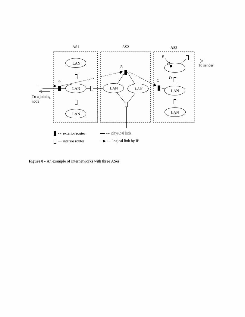
An example structure of a network from the viewpoint of exterior routing is shown in Figure 8, there are three
ASes: AS1, AS2 and AS3. For each AS, there are exterior routers: A, B, and C for AS1, AS2, and AS3, respectively.
The joining node is located at the left side of the figure and the sender at the right side. Router D is an interior router
in AS3 and host E is a multicast neighbor node of the joining node. Host E is directly connected to interior router D.
When a probe message arrives at router A, the DRPJ protocol will be executed at router A. Assuming that the probe
message should be farther propagated, the probe message is forwarded to the exterior router of the next AS, which is
router B. When the probe message reaches the AS where a multicast neighbor exists or the sender is located, the
exterior router in the AS extracts the list of traversed ASes from the probe message and sends the list in the reply
message directly back to the joining node using IP. Since exterior router C has a multicast neighbor node (host E),
router C sends the list of traversed AS IDs to the joining node using IP.
When a multicast neighbor exists in an AS, an internal router notifies its exterior router. The existence of a
multicast neighbor can be sent from the host (i.e., the multicast neighbor node) to an internal router using the Internet
Group Management Protocol (IGMP) [17]. In Figure 8, as long as host E is active as a multicast neighbor, the
existence of host E is reported to the internal router D using IGMP. While an internal router has an active multicast
neighbor, the existence of the multicast neighbor is reported to the exterior router in the AS using I-BGP.
5. Evaluation of the DRPJ Protocol
13
Simulation experiments were performed to evaluate and compare the Flooding with TTL, DSJ, and DRPJ
protocols. This section contains a description of the simulation model, experiments conducted, and results.
5.1 The simulation model
The measurement of interest in this simulation study is the number of probe messages generated by the three
multicast routing protocols when nodes connect to a multicast tree. Each minute, the number of probe messages
generated in a network was counted. A time-based simulation model was built using C++. The source code for the
simulator is available from the authors at [20]. The network topology used for this simulation study is based on the
actual AS network of the current Internet collected by NLANR (Asconnpairs20000102.txt) [27]. The network has
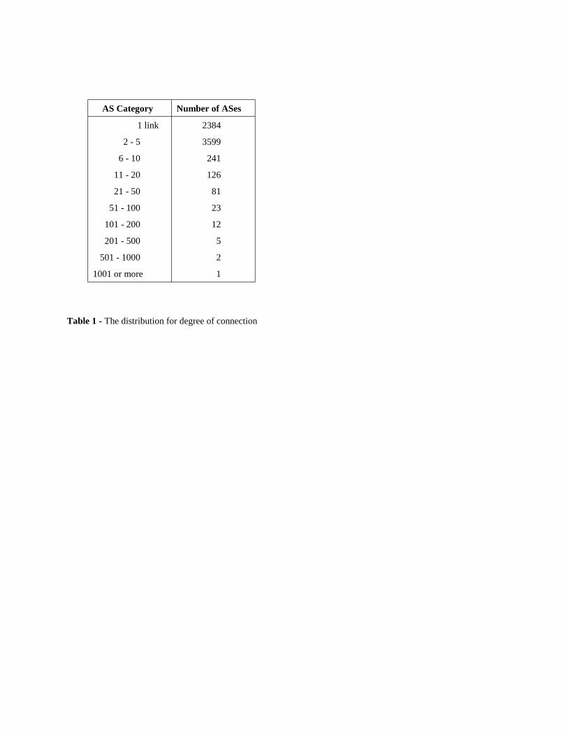
the following properties: number of distinct ASes = 6,474, AS links = 13,895, average degree of connectivity = 3.88,
and variance in degree of connectivity is 624.9. The distribution for degree of connectivity is shown in Table 1. The
control variables in our simulation model are receiver behavior, relative location of a sender, and the delay bound in
hop count.
For receiver behavior, there are two variables: session-holding time and inter-session time. Receiver behavior
consists of joining or leaving a multicast tree with a probabilistic session-holding time between a join and a leave.
The relative location of a sender is based on the distance to the other ASes in the network [28]. The variable is the
degree of connectivity at an AS. When we analyzed the shortest distance to all other nodes in the AS network, it was
observed that the more links an AS has the shorter the distance to the other ASes in the network. This observation
implies that the ASes with large degree of connectivity are in the core of the network. This also implies that the
more links an AS has, the closer the AS is to the core of the network. Each AS node with a high degree of
connectivity is considered a core AS. Conversely, an AS with a very few links is considered a remote AS node. For
example, those ASes with only one link generally have a longer distance to other ASes than core ASes. However, if
an AS is located near a center AS then the distance to other ASes is generally shorter than those that are not close to
any core ASes. We regard such AS nodes with a very few links, such as nodes with single link and long distance to
other AS nodes in the network, to be remote ASes. For the delay bound of the resulting paths, the distance in hop
count from a joining node and a sender was used. The control variable is the extra hops beyond the shortest distance
between a joining node and a sender.
14
We modeled joining intervals based actual traces from MBONE sessions. MBONE was chosen because of its
diverse types of applications with varied session-holding and inter-session times. It is expected that the receiver
behavior patterns, as well as network topologies, will have significant impact on the performance of multicast routing
protocols, thus it is important to have a broad range of session-holding and inter-session times. To simulate the
difference in the number of local hosts in each AS, we used the degree of connectivity at each AS. For those ASes
that have more than one link, simulations of receiver behavior were repeated with overlapped session-holding times.
For example, for an AS with 100 links we repeated the receiver behavior 100 times. We modeled group members
based on our assumption that the size of an AS (i.e., the number of local hosts within an AS) is proportional to the
degree of connectivity for each AS. There are no existing studies of the distribution of local hosts in the Internet,
thus we assumed that the degree of connectivity is one of the indicators for the size of ASes.
5.2 Evaluation experiments
Simulation experiments were designed to evaluate the effects of receiver behavior, location of a sender, and
delay bounds on the performance of a multicast protocol. Of interest are the mean and maximum number of probe
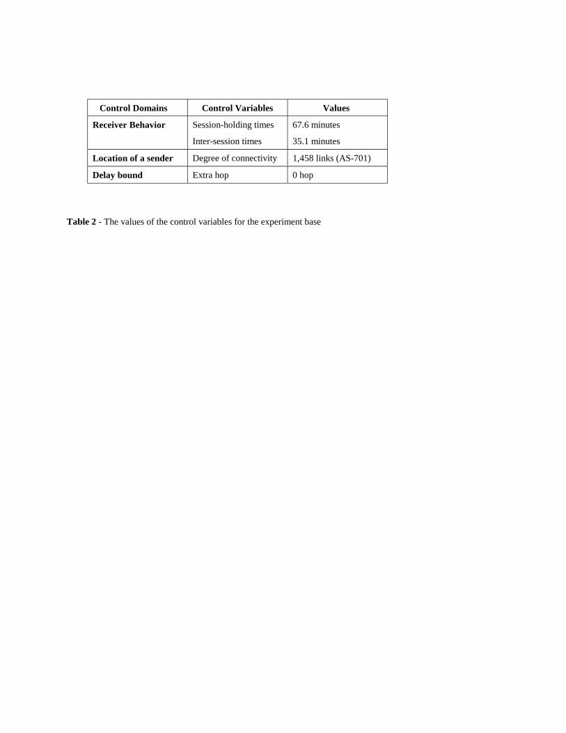
messages in the Internet. The “base case” for all experiments is as follows: for receiver behavior, the mean session-
holding time was 35.7 minutes and the mean inter-session time was 67.1 minutes. This is based on the representative
receiver behavior of an MBONE session in the “Free BSD Lounge” [1]. For the relative location of a sender, one of
the AS core nodes, AS-701, with 1,485 links [27] was chosen. This AS has the largest number of links of all ASes in
the current Internet. For the delay bound, only the shortest path (i.e., 0 extra hops) was used for our base case. The
parameters of this base case were then varied as described below. All experiments were run for a simulated two days
of time.
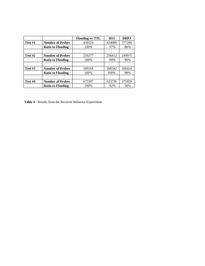
• Receiver behavior experiment - To measure the effects of receiver behavior, session holding and inter-
session times were varied. The mean receiver session-holding time and the mean inter-session time were
taken from MBONE multicast user session traces [1]. Inter-session times were assumed to be
exponentially distributed. Session-holding times were modeled as Pareto distributed [21] following from
observations in [1] that session-holding times are heavy tailed. The following tests were run:
− Test #1 - Base configuration.
15
− Test #2 - Session-holding time was halved from the base configuration.
− Test #3 - Inter-session time was doubled from the base configuration.
− Test #4 - Inter-session time was halved and a session holding time of 5 minutes was tested.
Test #4 evaluates the effects of sparse membership.
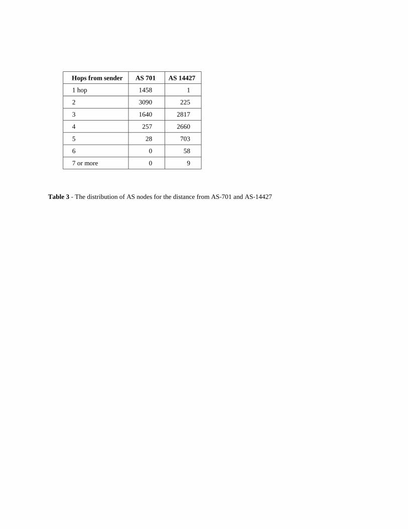
• Sender location experiment - To measure the effects of sender location, the degree of connectivity at a
sender was varied. The AS chosen as a remote sender was AS-14427. The distributions of AS nodes in
the AS network, in terms of their distance from AS-701 and AS-14427, are shown in Table 2. Tests #5
through #8 were run with each test respectively the same as Tests #1 though #4 except that the sender was
a remote AS, AS-14427.
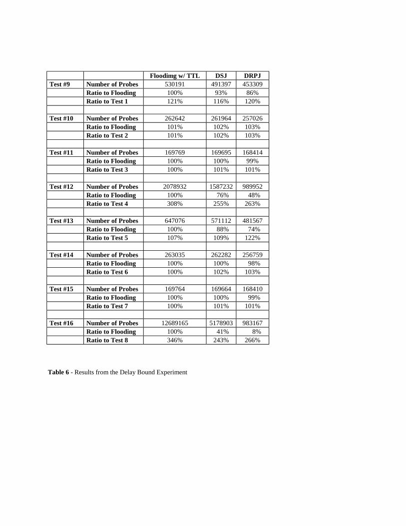
• Delay bound experiment - To measure the effects of the delay bound in the resulting paths, the three
multicast routing protocols were configured to detect all multiple paths with certain delay bound in the hop
count. Delay bound of the resulting paths was controlled by the extra hop beyond the distance between a
joining AS and a sender AS. This means that if the extra hop is 0, then the delay bound of the resulting
paths is simply the shortest path in the hop count while if the extra hop is 1, then the delay bound of the
resulting paths is the shortest path between a joining node and a sender plus one hop. For the Flooding
with TTL protocol this was done by setting the TTL field in the probe messages as the distance between a
joining node and a sender plus extra hop. For the DSJ protocol, both the TTL field and the METRICD field
were set to be the distance between a joining node and a sender plus extra hop. For the DRPJ protocol,
this was done via the MDD field. Tests #9 through #16 were run with each test respectively the same as
Tests #1 through #8 except that the extra hop was increased to one hop.
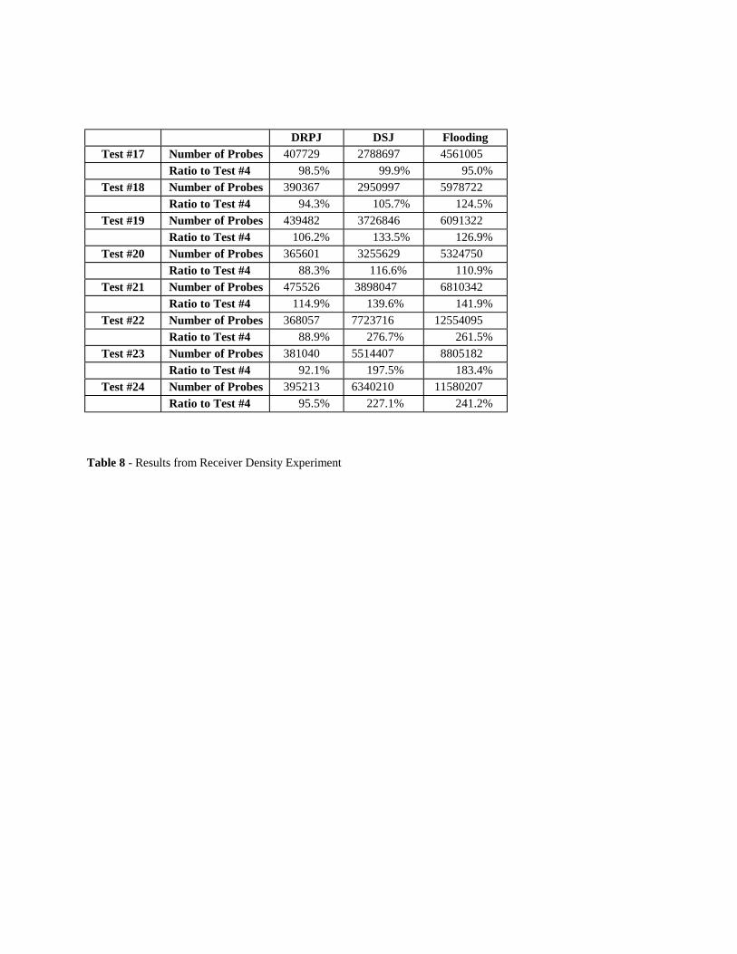
• Receiver density experiment - To study the effects of multicast receiver density, the number of multicast
receivers was reduced in Test #8. To control the receiver density, some nodes were randomly chosen as
inactive nodes. Inactive nodes are those that will never join the multicast session. In this experiment, 10%
to 80% (in increments of 10%) of all nodes in the network were randomly chosen as inactive nodes. The
sender AS (AS-14427), mean session-holding and inter-session times were the same as in experiment #1-
D. In test #17 through test #24, the numbers of the probe messages generated by the Flooding with TTL,
DSJ and DRPJ protocols were counted for each of the eight different types of receiver density.

16
5.3 Experiment results and discussion
Tables 3, 4 and 5 and Figures 9, 10, and 11 show the result of the three experiments. It can be seen that when
multicast receivers are sparsely scattered in the network (Tests #4, #8, #12, and #16), Flooding with TTL and DSJ
protocols result in more probe messages (994% and 430% more probe messages than the DRPJ protocol). The raw
outputs from Test #4 are shown in Figure 9, 10, and 11 for the three protocols. The reduction in probe messages due
to the DRPJ protocol can clearly be seen by comparing the three figures.
Table 5 shows the relative increase of probe messages when we increased the delay bound of the three multicast
routing protocols by one hop. Increasing the delay bound by one hop searched a path from a joining node that was
one hop longer than the shortest distance between the joining node and the sender. Increases are shown in percent
relative to the results with no extra hop (Tests #1 through #8). The three multicast routing protocols showed similar
scaling properties, except for the Flooding with TTL protocol which resulted in greater increase in the number of
probe messages (about 30% more increase than the DSJ and DRPJ protocols).
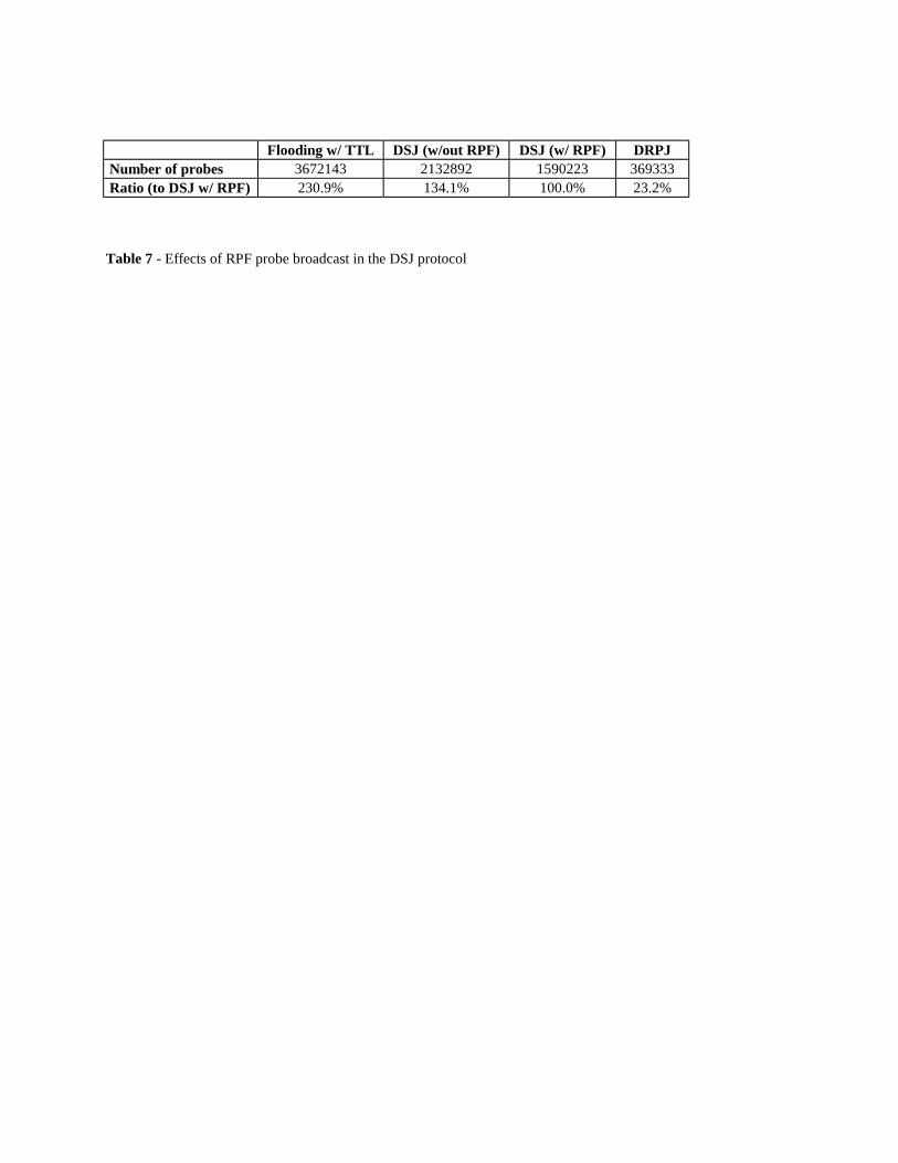
The DSJ pseudocode in Figure 4 shows that the number of probe messages are limited using two conditions: 1)
RPF broadcast of probe messages, and the directional guidance given by the METRICD field (lines 6 and 7 in Figure 4).
To see the effect of RPF probe broadcasting in the DSJ protocol, the DSJ protocol was tested without the RPF
broadcasting constraint. Removing line 6 in Figure 4 did this. This experiment was performed under the same
conditions used in Test #8. Table 7 shows the results of this experiment. It was observed that the effect of the RPF
probe broadcast was only 15% (58% in the DSJ protocol without RPF probe broadcast and 43% in the DSJ protocol
with RPF probe broadcast) relative to the Flooding with TTL protocol in this particular case. In the DRPJ protocol,
probe messages are also broadcast from a joining node to other nodes along the shortest paths to them. Thus, the
major difference between the DSJ protocol (with RPF probe broadcast) and the DRPJ protocol is that the length of a
resulting path is considered in the DRPJ protocol in making a decision whether a probe message should be further
broadcast, while it is not in the DSJ protocol. Since this is the only difference between the DSJ and DRPJ protocols,
it contributes to a reduction of about 76% of probe messages from the DSJ protocol (Table 6).
17
Table 8 shows the results from receiver density experiment. The graph shows the probe message increase
relative to the cases without any receiver reduction for the Flooding with TTL, DSJ and DRPJ protocols. From
Figure 12, it can be seen that the Flooding with TTL and DSJ protocols resulted in more messaging overhead, up to
262% and 276% for the Flooding with TTL and DSJ protocols respectively, as multicast receiver density decreases.
In the DRPJ protocol, this increase was at most 15% throughout the experiment.
The most plausible reason for the inefficiency of the Flooding with TTL and DSJ protocols for a remote sender
and sparse receivers is that the distances from a sender to multicast neighbor nodes are longer than for a core sender
with dense receivers. Since a path for a multicast session is formed as a tree, the multicast tree with a core AS as its
root in a tree with low height is a broad tree. Multicast trees to be formed for remote AS senders are expected to
have opposite characteristics than those for core ASes. Since the distance from a sender to the other ASes will be
longer than those for core ASes, the resulting multicast trees should be high and thus also narrow. The propagation
of probe messages will be wider, which results in a larger messaging overhead even for multicast neighbor searches.
From the observations made in the receiver density experiment, it can be seen that the DRPJ multicast routing
protocol generates less messaging overhead when multicast receivers are sparsely distributed. From this result, it is
also concluded that the DRPJ protocol is less sensitive to receiver density than the Flooding with TTL and DSJ
protocols, while the DRPJ protocol also generates significantly less messaging overhead in the absolute number of
probe messages.
6. Summary and Future Work
The new Directed Reverse Path Join (DRPJ) multicast protocol was proposed and evaluated in this paper.
Evaluation shows that the most significant factors for performance of multicast routing protocols are the density of
multicast receivers and the relative position of the AS with regard to the sender from the core ASes. We showed that
two existing protocols - the Flooding with TTL [11] and the DSJ protocols [5] - are inefficient in handling remote
sender nodes located at a long distance from core ASes. This was true especially when multicast receivers were
sparsely scattered in the Internet. The simulation experiments show that the DRPJ protocol reduces many
unnecessary probe messages. For the case where receivers are sparsely scattered and a sender is a remote AS, the
18
DRPJ protocol results in about 10% of the probe messages generated by the Flooding with TTL protocol and 25% of
the DSJ protocol. It was observed that the multicast routing protocols evaluated in this study depend on how
multicasting applications are used (i.e., the location of the senders and the multicast receiver behavior). As multicast
becomes more commonly used, actual measurements of probe overhead in the Internet should be made. These
measurements can further guide the investigation of effective and efficient multicast protocols.
19
References [1] K. Almeroth and M. Ammar, “Multicast Group Behavior in the Internet’s Multicast Backbone (MBONE),”
IEEE Communications Magazine, 35 (6) June (1997) 124 - 129 [2] K. Almeroth, “The Evolution of Multicast: From the MBone to Interdomain Multicast to Internet2
Deployment,” IEEE Network, 14 (1) January-February (2000) 10 - 20 [3] A. Ballardie, P. Francis, and J. Crowcroft, “Core Based Trees (CBT),” Proceedings of ACM SIGCOMM,
September (1993) 85 - 95 [4] T. Bates, R. Chandra, D. Katz, and Y. Rekhter, “Multiprotocol Extensions for BGP-4,” RFC 2283, February
(1998). [5] K. Carlberg and J. Crowcroft, “Building Shared Trees Using a One-to-Many Joining Mechanism,” Computer
Communication Review, 27 (1) January (1997) 5 - 11 [6] K. Calvert, E. Zegura, and S. Bhattacharjee, “How to Model an Internetwork,” Proceedings of IEEE
INFOCOM, May (1996) 594 - 602. [7] K. Calvert, M. Doar, and A. Nexion, “Modeling Internet Topology,” IEEE Communications Magazine, 35 (6)
June (1997) 160 - 163. [8] S. Chen and K. Nahrstedt, “An Overview of Quality of Service Routing for Next-Generation High-Speed
Networks: Problems and Solutions,” IEEE Network, 12 (6) November-December (1998) 64 - 79. [9] The CIDR Report, URL: http://www.employees.org:80/~tdates/cidr-report.html. [10] S. Deering, “Distance Vector Multicast Routing Protocol,” RFC 1075, November (1988). [11] S. Deering and D. Cheriton, “Multicast Routing in Datagram Internetworks and Extended LANs,” ACM
Transactions on Computer Systems, 8 (2) May (1990) 85 - 110. [12] S. Deering, D. Estrin, D. Farinacci, V. Jacobson, C. Liu, and L. Wei, “The PIM Architecture for Wide-Area
Multicast Routing,” IEEE/ACM Transactions on Networking, 4, (2) April (1996) 153 - 162. [13] M. Doar and I. Leslie, “How Bad is Naive Multicast Routing?,” Proceedings of IEEE INFOCOM, November
(1993) 82 - 89. [14] D. Estrin and K. Obraczka, “Connectivity Database Overhead for Inter-Domain Policy Routing,” Proceedings
of IEEE INFOCOM, April (1991) 256 - 278. [15] D. Estrin, Y. Rekhter, and S. Hotz, “Scalable Inter-Domain Routing Architecture,” Computer Communication
Review, 22 (4) (1992) 40 - 52. [16] D. Farinacci et al., “Multicast Source Discovery Protocol (MSDP),” Internet Draft, February (2000). [17] W. Fenner, “IGMP Version 2,” RFC 2236, November (1997). [18] H. Fujinoki and K. Christensen, “The New Shortest Best Path Tree (SBPT) Algorithm for Dynamic Multicast
Trees,” Proceedings of the IEEE 24th Conference on Local Computer Networks, October (1999) 204 - 211.
20
[19] H. Fujinoki and K. Christensen, “A Routing Algorithm for Dynamic Multicast Trees with End-to-End Path Length Control,” Computer Communications, 23 (2) January (2000) 101 - 114.
[20] H. Fujinoki, Simulator Software for Multicast Routing Protocols, (2000).
URL: http://www.csee.usf.edu/fujihir/DRPJ.html. [21] J. Gordon, “Pareto Process as a model of Self-Similar Packet Traffic,” Proceedings of IEEE GLOBECOM,
April (1997) 2232 - 2235. [22] R. Govindan and A. Reddy, “An Analysis of Internet Inter-Domain Topology and Route Scalability,”
Proceedings of IEEE INFOCOM, September (1997) 850 - 857. [23] H. Hobrook and D. Cheriton, “IP Multicast Channels: EXPRESS Support for Large-Scale Single-Source
Applications,” Computer Communication Review, 29 (4) (1999) 65 - 78. [24] Internet Host and Traffic Growth, University of Columbia,
URL: http://www.cs.columbia.edu/~hgs/internet/growth.html. [25] J. Mcquillan, I. Richer, and E. Rosen, “The New Routing Algorithm for the ARPANET,” IEEE Transactions
on Communications, 28 (5), May (1980) 711 - 719. [26] J. Moy, “OSPF Version 2,” RFC 1584, March (1994). [27] The National Laboratory for Applied Network Research (NLANR), URL: http://moat.nlanr.net. [28] J. Pansiot and D. Grad, “On Routes and Multicast Trees in Internet,” Computer Communication Review, 28 (1)
January (1998) 41 - 50. [29] E. Rosen, “Exterior Gateway Protocol,” RFC 827, October (1982). [30] A. Shankar, C. Alaettininoglu, I. Matta, and K. Dussa Zieger, “Performance Comparison of Routing Protocols
using MaRS: Distance-Vector versus Link-State”, Performance Evaluation Review, 20 (1) (1992) 181 - 192. [31] P. Traina, “BGP-4 Protocol Analysis,” RFC 1774, March (1995). [32] B. Waxman, “Routing of Multipoint Connections,” IEEE Journal of Selected Areas in Communications, 6 (9)
December (1988) 1617 - 1622. [33] L. Wei and D. Estrin, “Multicast Routing in Dense and Sparse Modes: Simulation Study of Tradeoffs and
Dynamics,” Proceedings of the Fourth International Conference on Computer Communications and Networks, September (1995) 150 - 157.
[34] W. Zaumen, W. and J. Garcia-Luna-Aceves, “Dynamics of Link-State and Loop-Free Distance-Vector Routing
Algorithms,” Journal of Internetworking: Research and Experience, 3 (4) December (1992) 161 - 188.
Figure and Tables • Figure 1 - The Unbounded Flooding Protocol
• Figure 2 - Area of probe messages propagated using the Flooding with TTL protocol
• Figure 3 - The Flooding with TTL protocol
• Figure 4 - The DSJ protocol
• Figure 5 - Pathological case for the DSJ protocol
• Figure 6 - The DRPJ protocol at an intermediate node i
• Figure 7 - The NEIGHBORSEARCH message
• Figure 8 - An example of internetworks with three ASes
• Figure 9 - The number of generated probe messages for the Flooding with TTL protocol (Test #8 - AS-14427)
• Figure 10 - The number of generated probe messages for the DSJ protocol (Test #8 - AS-14427)
• Figure 11 - The number of generated probe messages for the DRPJ protocol (Test #8 - AS-14427)
• Figure 12 - Increase in the amount of generated probe messages for different receiver densities
• Table 1 - The distribution for degree of connection
• Table 2 - The values of the control variables for the experiment base
• Table 3 - The distribution of AS nodes for the distance from AS-701 and AS-14427
• Table 4 - Results from the Receiver Behavior Experiment
• Table 5 - Results from the Sender Location Experiment
• Table 6 - Results from the Delay Bound Experiment
• Table 7 - Effects of RPF probe broadcast in the DSJ protocol
• Table 8 - Results from Receiver Density Experiment
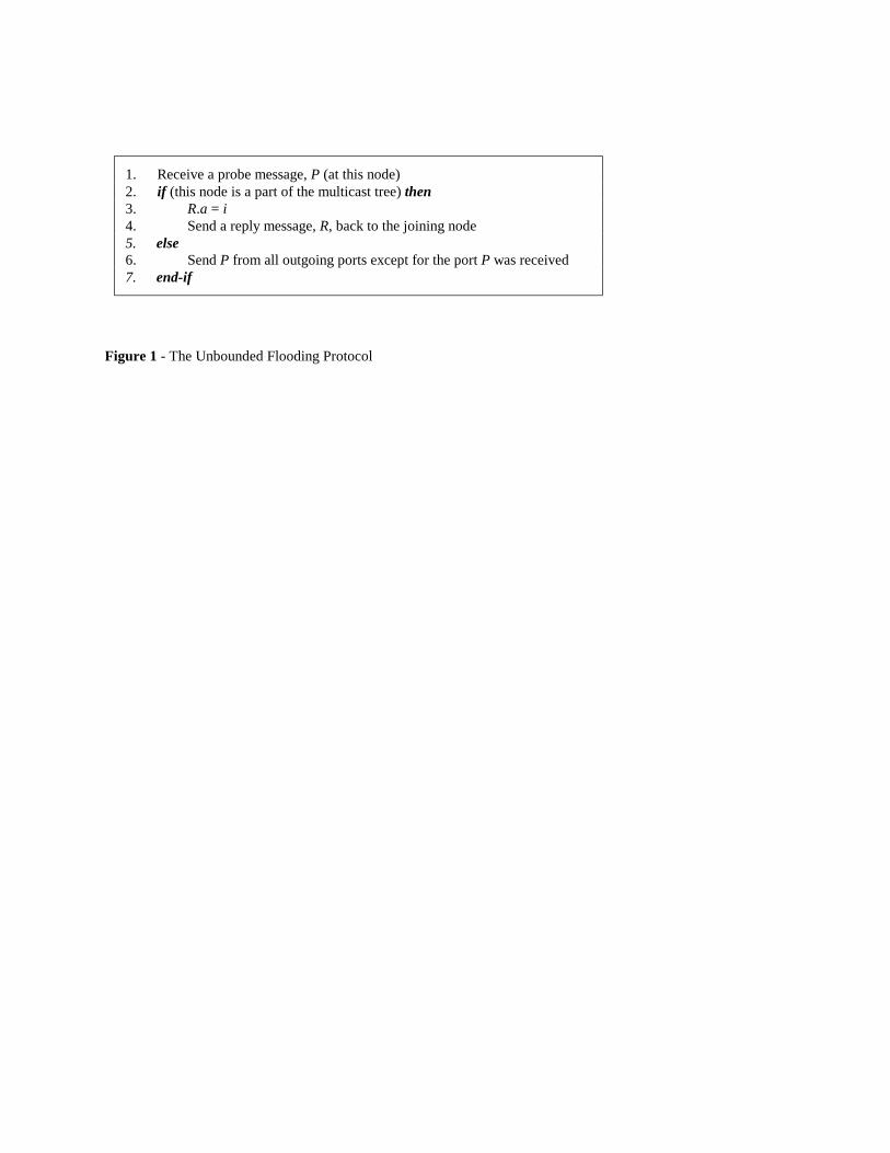
1. Receive a probe message, P (at this node) 2. if (this node is a part of the multicast tree) then 3. R.a = i 4. Send a reply message, R, back to the joining node 5. else 6. Send P from all outgoing ports except for the port P was received 7. end-if
Figure 1 - The Unbounded Flooding Protocol
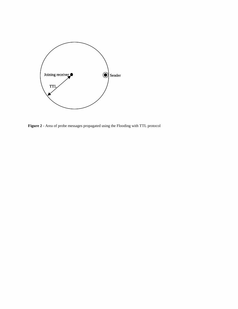
Figure 2 - Area of probe messages propagated using the Flooding with TTL protocol
TTL
SenderJoining receiver
TTL
SenderJoining receiver
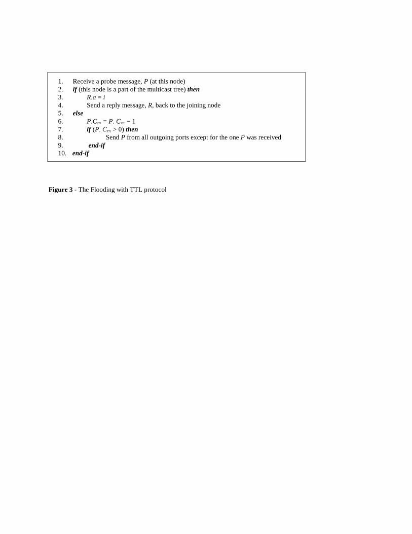
1. Receive a probe message, P (at this node) 2. if (this node is a part of the multicast tree) then 3. R.a = i 4. Send a reply message, R, back to the joining node 5. else 6. P.CTTL = P. CTTL − 1 7. if (P. CTTL > 0) then 8. Send P from all outgoing ports except for the one P was received 9. end-if 10. end-if
Figure 3 - The Flooding with TTL protocol
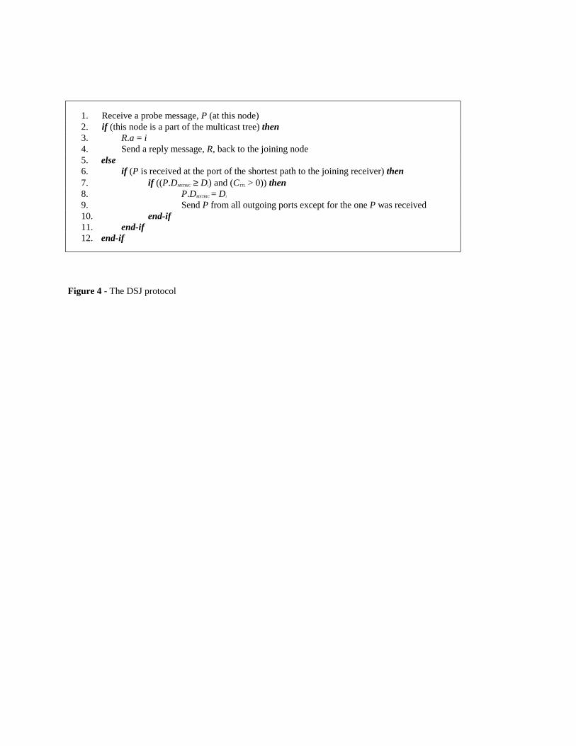
1. Receive a probe message, P (at this node) 2. if (this node is a part of the multicast tree) then 3. R.a = i 4. Send a reply message, R, back to the joining node 5. else 6. if (P is received at the port of the shortest path to the joining receiver) then 7. if ((P.DMETRIC ≥ Di) and (CTTL > 0)) then 8. P.DMETRIC = Di 9. Send P from all outgoing ports except for the one P was received 10. end-if 11. end-if 12. end-if
Figure 4 - The DSJ protocol
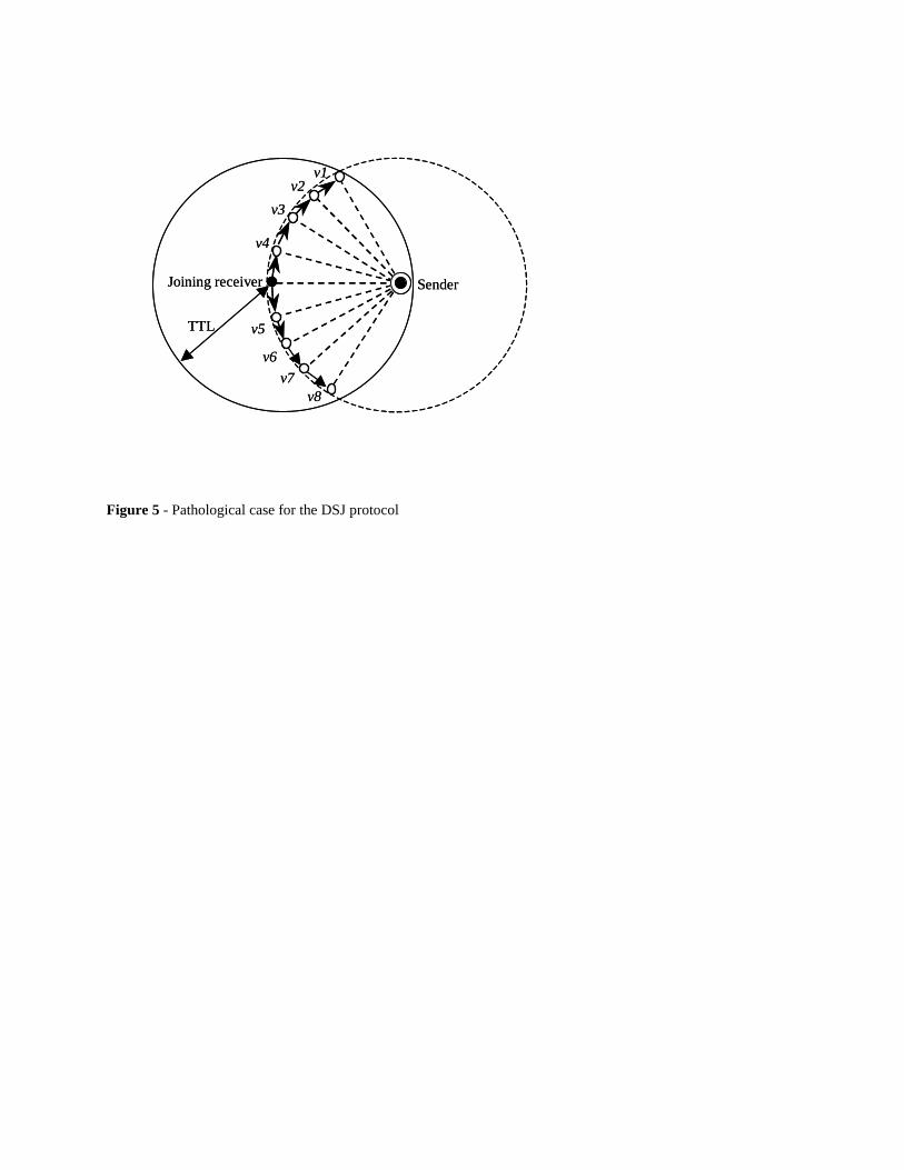
Figure 5 - Pathological case for the DSJ protocol
v1v2
v3
v4
v5
v6v7
v8
TTL
SenderJoining receiver
v1v2
v3
v4
v5
v6v7
v8
TTL
SenderJoining receiver
1. Receive a probe message, P 2. if (this node is a part of the tree for the sender) then 3. R.a = i and R.b = Di 4. Send a reply message, R, back to the joining node 5. else 6. P.CTTL = P.CTTL − 1 7. if (P.CTTL > Di) then 8. Send P from all outgoing ports except for the one P was received 9. end-if 10. end-if
Figure 6 - The DRPJ protocol at an intermediate node i
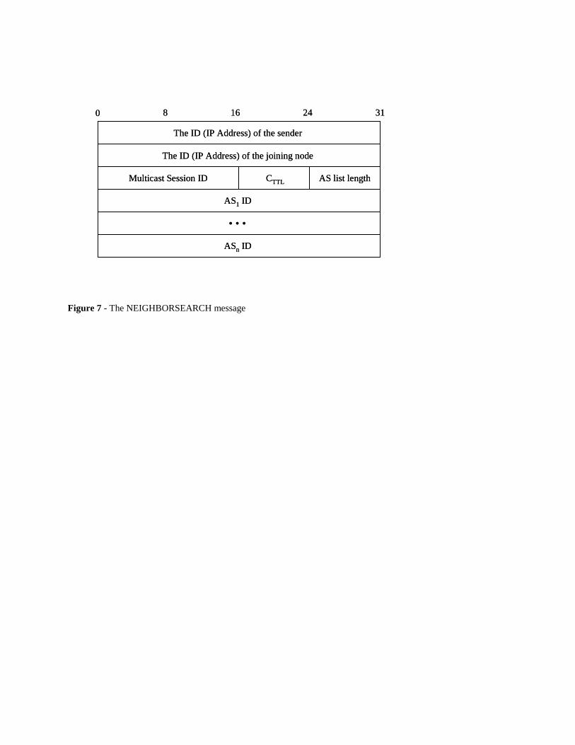
Figure 7 - The NEIGHBORSEARCH message
The ID (IP Address) of the sender
The ID (IP Address) of the joining node
AS1 ID
ASn ID
• • •
Multicast Session ID CTTL AS list length
0 8 16 24 31
The ID (IP Address) of the sender
The ID (IP Address) of the joining node
AS1 ID
ASn ID
• • •
Multicast Session ID CTTL AS list length
0 8 16 24 31
B
AS2
To a joining node
exterior router
interior router
physical link
logical link by IP
A
AS1
LAN
LAN
LAN
LAN LAN
C
AS3
D
E
To sender
LAN
LAN
Figure 8 - An example of internetworks with three ASes
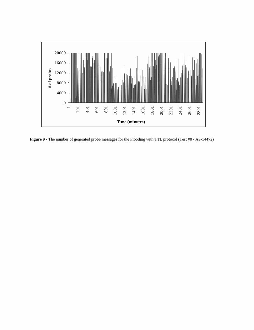
Figure 9 - The number of generated probe messages for the Flooding with TTL protocol (Test #8 - AS-14472)
0
4000
8000
12000
16000
20000
1
201
401
601
801
1001
1201
1401
1601
1801
2001
2201
2401
2601
2801
Time (minutes)
# of
pro
bes
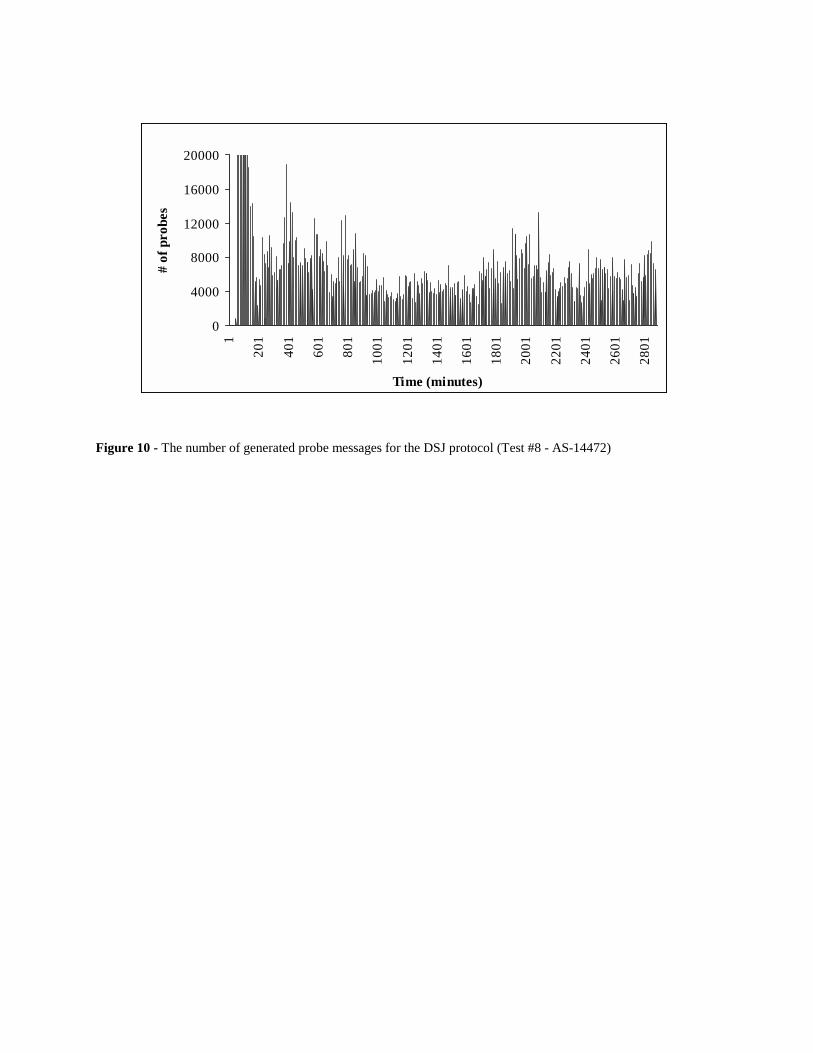
Figure 10 - The number of generated probe messages for the DSJ protocol (Test #8 - AS-14472)
0
4000
8000
12000
16000
20000
1
201
401
601
801
1001
1201
1401
1601
1801
2001
2201
2401
2601
2801
Time (minutes)
# of
pro
bes
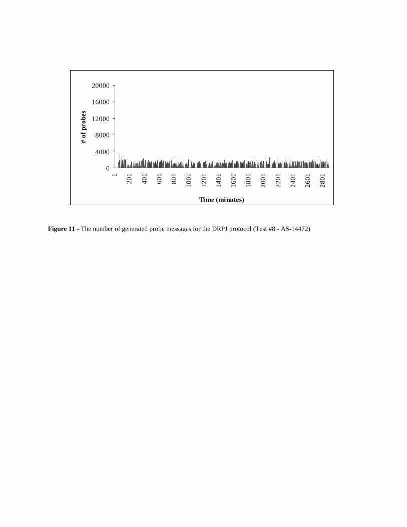
Figure 11 - The number of generated probe messages for the DRPJ protocol (Test #8 - AS-14472)
0
4000
8000
12000
16000
20000
1
201
401
601
801
1001
1201
1401
1601
1801
2001
2201
2401
2601
2801
Time (minutes)
# of
pro
bes
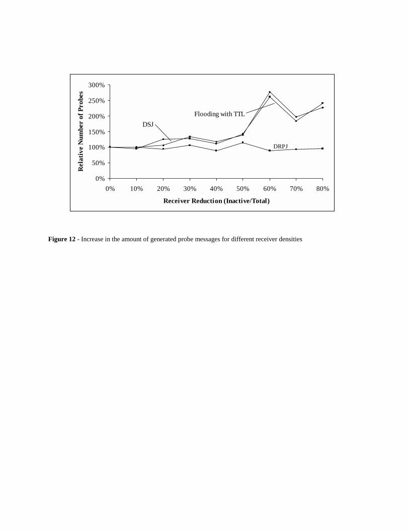
Figure 12 - Increase in the amount of generated probe messages for different receiver densities
0%
50%
100%
150%
200%
250%
300%
0% 10% 20% 30% 40% 50% 60% 70% 80%
Receiver Reduction (Inactive/Total)
Rel
ativ
e N
umbe
r of
Pro
bes
DSJFlooding with TTL
DRPJ
AS Category Number of ASes
1 link
2 - 5
6 - 10
11 - 20
21 - 50
51 - 100
101 - 200
201 - 500
501 - 1000
1001 or more
2384
3599
241
126
81
23
12
5
2
1 Table 1 - The distribution for degree of connection
Control Domains Control Variables Values
Receiver Behavior Session-holding times
Inter-session times
67.6 minutes
35.1 minutes
Location of a sender Degree of connectivity 1,458 links (AS-701)
Delay bound Extra hop 0 hop Table 2 - The values of the control variables for the experiment base
Hops from sender AS 701 AS 14427
1 hop 1458 1
2 3090 225
3 1640 2817
4 257 2660
5 28 703
6 0 58
7 or more 0 9 Table 3 - The distribution of AS nodes for the distance from AS-701 and AS-14427
Flooding w/ TTL DSJ DRPJ Test #1 Number of Probes 439324 424089 377289 Ratio to Flooding 100% 97% 86% Test #2 Number of Probes 259277 256412 249975 Ratio to Flooding 100% 99% 96% Test #3 Number of Probes 169164 168342 166424 Ratio to Flooding 100% 100% 98% Test #4 Number of Probes 675397 623736 375928 Ratio to Flooding 100% 92% 56% Table 4 - Results from the Receiver Behavior Experiment

Flooding w/ TTL DSJ DRPJ Test #5 Number of Probes 62705 522491 394150 Ratio to Flooding 100% 87% 65% Test #6 Number of Probes 262891 257097 250046 Ratio to Flooding 100% 98% 95% Test #7 Number of Probes 169750 168451 166586 Ratio to Flooding 100% 99% 98% Test #8 Number of Probes 3672143 1590223 369333 Ratio to Flooding 100% 43% 10% Table 5 - Results from the Sender Location Experiment
Floodimg w/ TTL DSJ DRPJ Test #9 Number of Probes 530191 491397 453309 Ratio to Flooding 100% 93% 86% Ratio to Test 1 121% 116% 120% Test #10 Number of Probes 262642 261964 257026 Ratio to Flooding 101% 102% 103% Ratio to Test 2 101% 102% 103% Test #11 Number of Probes 169769 169695 168414 Ratio to Flooding 100% 100% 99% Ratio to Test 3 100% 101% 101% Test #12 Number of Probes 2078932 1587232 989952 Ratio to Flooding 100% 76% 48% Ratio to Test 4 308% 255% 263%
Test #13 Number of Probes 647076 571112 481567 Ratio to Flooding 100% 88% 74% Ratio to Test 5 107% 109% 122% Test #14 Number of Probes 263035 262282 256759 Ratio to Flooding 100% 100% 98% Ratio to Test 6 100% 102% 103% Test #15 Number of Probes 169764 169664 168410 Ratio to Flooding 100% 100% 99% Ratio to Test 7 100% 101% 101% Test #16 Number of Probes 12689165 5178903 983167 Ratio to Flooding 100% 41% 8% Ratio to Test 8 346% 243% 266% Table 6 - Results from the Delay Bound Experiment
Flooding w/ TTL DSJ (w/out RPF) DSJ (w/ RPF) DRPJ Number of probes 3672143 2132892 1590223 369333 Ratio (to DSJ w/ RPF) 230.9% 134.1% 100.0% 23.2% Table 7 - Effects of RPF probe broadcast in the DSJ protocol
DRPJ DSJ Flooding Test #17 Number of Probes 407729 2788697 4561005
Ratio to Test #4 98.5% 99.9% 95.0% Test #18 Number of Probes 390367 2950997 5978722
Ratio to Test #4 94.3% 105.7% 124.5% Test #19 Number of Probes 439482 3726846 6091322
Ratio to Test #4 106.2% 133.5% 126.9% Test #20 Number of Probes 365601 3255629 5324750
Ratio to Test #4 88.3% 116.6% 110.9% Test #21 Number of Probes 475526 3898047 6810342
Ratio to Test #4 114.9% 139.6% 141.9% Test #22 Number of Probes 368057 7723716 12554095
Ratio to Test #4 88.9% 276.7% 261.5% Test #23 Number of Probes 381040 5514407 8805182
Ratio to Test #4 92.1% 197.5% 183.4% Test #24 Number of Probes 395213 6340210 11580207
Ratio to Test #4 95.5% 227.1% 241.2% Table 8 - Results from Receiver Density Experiment