Embed Size (px)
Citation preview

The Diagnostic Architecture of the PEGASUSProject Car
P. Peti1, R. Obermaisser1, and H. Paulitsch1
1Institute of Computer Engineering,Real-Time Systems Group,
Vienna University of Technology, Austria{peti,romano,harald}@vmars.tuwien.ac.at
Abstract — The automotive industry is at the verve to deploy computer systemsnot only for safety-related and comfort functionality, but for safety-critical by-wiresystems. In the scope of the PEGASUS project a car will be equipped with time-triggered technology in order to provide not only superior car dynamics but alsoinvestigate system design and integration on the basis of a series car. As part of thisproject a diagnostic solution is being developed in order to tackle prevalent diagnos-tic problems, such as the trouble-not-identified phenomenon in electronic systems, byexploiting the error-containment properties of the underlying architecture.In this paper we present the diagnostic architecture of the PEGASUS car that op-erates on the distributed state of the system in order to trace experienced failuresback to the origin and decide on the type of fault (e.g., transient vs. permanent, in-ternal vs. external) that is affecting the system. A necessary prerequisite of suchan integrated diagnostic infrastructure is the continuous monitoring and subsequentdissemination of diagnostic information in order to allow a meaningful analysis.
1 Introduction
There is a significant trend in the automotive industry to increase the number of electronicdevices in automotive systems. It is estimated that more than 80% of all automotiveinnovations nowadays stem from electronics [1]. These numbers are underpinned byrecent studies of the automotive electronics market that show impressive growth rates inthe next four years [2].Today, the electronic infrastructure of a car consists of a high number of Electronic Con-trol Units (ECUs) (up to more than 70 in today’s luxury cars), each typically dedicatedto only one application service. The distributed ECUs are interconnected via commu-nication networks with different protocols (e.g., Controller Area Network (CAN) [3]),physical layers, bandwidths (10 kbps–500 kbps), and dependability requirements.However, despite all the benefits, it is important to state that with the increasing use ofelectronic devices in transportation systems the likelihood of malfunctions and thus thenumbers of defective electronic components will also increase. Nevertheless, diagnosticdemands are not solved satisfactorily by current communication systems within the car.
163

P. PETI, R. OBERMAISSER, AND H. PAULITSCH
Originally developed to provide simple open/short circuit and abnormal voltage leveldetection mechanisms, electronic diagnosis evolved into an integral part of every automo-bile. All modern cars are equipped with On-Board Diagnosis (OBD) systems (OBD-IIin USA or EOBD in Europe). OBD, originally developed to continuously monitor theemissions of a car, provides now almost complete engine control and also monitors partsof the chassis, body electronics, and the control network of the vehicle.However, the development of effective diagnostic systems has stayed behind the recentincrease of electronic systems in modern cars. One reason for the diagnostic deficienciesof modern OBD systems is the fact that diagnosis is often treated as add-on to commu-nication systems rather than an integral part of the architecture [4]. Consequently, theproblem of the identification of faulty ECUs is one of the predominant challenges thatneed to be solved.It takes six months on average for the service technicians at the garages to gain experi-ence with a new car (often due to insufficient technical documentation). However, today’seconomic pressure in the automotive industry forces the introduction of new car modelsin decreasing intervals. In recent years the vehicle development cycle was reduced fromfour to two years to cope with market demands [5]. These technological and businessrealities underpin the need for effective diagnosis methods.Though the breakdown logs of the ECUs inform the service technician about detectederrors within the system, they do not assist the technician adequately in the identificationprocess [5]. Thus, fully functional units are replaced, or even worse, faulty ECUs remainunchanged in the system. Several factors are relevant to allow for an effective diagnosis,but a pivotal one is the ability to provide error containment that enables the tracing of ex-perienced errors back to the origin. This necessary property is not sufficiently satisfied bythe predominant communication infrastructure in the automotive domain, the ControllerArea Network (CAN) protocol [3]. These diagnostic deficiencies will become more andmore obvious when X-by-wire solutions will be subject to mass production. EmergingX-by-wire solutions will have a lasting effect on the mechanics work, since computerdiagnostic will become a standard part of the job [1, 6]. Since a mechanic at a servicestation is no specialist in automobile electronics, the diagnostic system of the car mustprovide all necessary information that allows maintenance of faulty components. For thisreason it must be possible in modern automotive electronic architectures to trace an entryin a breakdown log back to its source. If this is not possible, as a consequence, fullyoperational units will be replaced by mistake.In the remainder of this document we discuss the diagnostic architecture as part of theelectronic infrastructure deployed on board of the PEGASUS project car that aims totackle prevalent diagnostic problems. In particular, this diagnostic solution focuses onproviding the maintenance engineer with the necessary information to decide whether areplacement of a particular component is the correct maintenance action. In the scopeof the project we will investigate to which extent the error containment and diagnosticproperties (e.g., membership) of TTP facilitate diagnosis for maintenance.The paper is structured as follows. In Section 2 the objective of the PEGASUS projectis described. Section 3 elaborates on today’s automotive diagnostic strategy. In Section 4the requirements of a future diagnostic architecture are discussed and Section 5 gives anoverview of the fundamental concepts behind the PEGASUS diagnostic architecture. The
164

THE DIAGNOSTIC ARCHITECTUREOF THE PEGASUS PROJECT CAR
paper is concluded in Section 6.
2 The PEGASUS Project
PEGASUS is a joint project between the companies TTTech Computertechnik AG 1, AudiAG Germany 2, and the Institute of Computer Engineering at the Vienna University ofTechnology funded by the Austrian Advanced Automotive (A3) Technology program ofthe Austrian Federal Ministry of Transport, Innovation and Technology 3.The primary objective of PEGASUS is to develop and to implement an application foradvanced electronic vehicle dynamics in a series-production vehicle on the basis of theTime-Triggered Architecture (TTA) [7]. The challenge thereby is the integration of thealready existing hardware and software architecture of the car on the basis of CAN [3]with the newly developed TTP [8] network controlling advanced powertrain functionalitysuch as dynamic four-wheel-drive. The ultimate goal is to increase vehicle stability incritical situations and achieve better driving agility. The TTA also establishes the founda-tion for reducing the number of electronic control units deployed in a modern car. As aconsequence thereof the need and cost for connectors and cabling will decrease as well.This substantial reduction of the electronic production costs for vehicle dynamics is ofgreat economic importance for car manufacturers.Furthermore, in the scope of the PEGASUS project new diagnostic strategies are in-vestigated in order to tackle prevalent maintenance problems such as the Trouble NotIdentified (TNI) phenomenon [9] and to realize advanced diagnostic strategies such asCondition-Based Maintenance (CBM) [10, 11] in the electronics domain. Thereby theerror containment capabilities of the TTA [12] will be fully exploited in order to providea more accurate diagnosis to substantially reduce the service times at the service stations.The PEGASUS project offers the opportunity to validate the advanced diagnostic con-cepts not only in a laboratory environment test setup but also in the field.
3 Today’s Automotive Diagnosis
Each ECU deployed in a car typically has an OBD subsystem that analyzes the function-ality of the constituting parts (e.g., via a Built-In Self Test (BIST)) or performs applicationspecific plausibility checks to detect errors.Once the OBD system of the car detects a violation of the specification of an ECU, abreakdown log entry is written. In case of a high severity, the driver is informed via theMalfunction Indicator Light (MIL). In case of an error, current diagnostic systems providea so called freeze frame function, that records the condition of the vehicle when a failureoccurs. The freeze frame provides important information for the failure cause analysis.The breakdown-log typically stores data on the type of fault, the state of the system, theseverity, the environmental conditions, a timestamp, and information on the milage of thecar.The maintenance engineer can use this collected data for getting insight into the contextof the system malfunction. However, this information is often insufficient to understand
1www.tttech.com2www.audi.de3www.bmvit.gv.at
165
P. PETI, R. OBERMAISSER, AND H. PAULITSCH
the complex processes within the system that has caused the system to fail. Dependingon the type of inspection (e.g., garage, factory inspection, development) different parts ofthe breakdown log entry are analyzed.In maintenance mode the ECUs are accessed using dedicated protocols like ISO-9141,J1850 or the CAN based Keyword Protocol (KWP) 2000 [13, 14]. At the service sta-tion the mechanic uses a diagnostic testing device to receive information about pendingproblems. Since most mechanics are no specialists in automotive electronics, the servicetechnician depends on the accuracy of the diagnostic information provided by the OBD.Based on this information the mechanics must be able to determine which part of the sys-tem has caused the failure and whether a replacement restores the intended functionality.
4 Requirements for Future Diagnostic Solutions
Any diagnostic solution needs to meet the following requirements in order to reduce thefault-not-found ratio and its far reaching economic implications in electronic systems.
– Service Technician Assistance. Since a mechanic is usually no specialist in elec-tronics, the diagnostic system must provide all necessary information that allows theidentification of faulty Field Replaceable Units (FRUs) [1]. If this is not possible,fully operational units will be replaced by mistake.
– Focus on Transients. The types and causes of failures for electronics have changedover the years. Failure analysis in recent years has revealed that permanent failureshave been reduced by improvements in technology but due to the higher level ofcomplexity and downsizing other failure classes have emerged [15]. The tremen-dous improvements made by the IC industry with respect to permanent failure ratesare extenuated by increasing transient failure rates for instance due to semiconduc-tor process variations, shrinking geometries, and lower power voltages [16]. Conse-quently, the diagnostic services must especially be designed to handle transients.
– Detection of Correlated Errors. Diagnostic systems operating only on the internalcomponent state preclude the possibility to detect and analyze correlated failures orsystem anomalies at different nodes. Thus, a diagnostic architecture must providemeans to establish a holistic view of the system by operating on the distributed state.
– Assessment of Fault-Tolerance Mechanisms. Fault-tolerance mechanisms are re-quired to achieve the necessary degree of dependability for the deployment of elec-tronic systems in safety-critical environments. In order to reduce application com-plexity and certification efforts, fault-tolerance mechanisms are ideally provided bythe architecture and exploited transparently to the application. However, from adiagnostic point of view, this strategy has far reaching implications. Since it is im-possible to detect inconsistency of the fault-tolerant replicas at the application level,diagnostic mechanisms must be provided at architecture level.
– Support for AdvancedMaintenance Strategies. Time-BasedMaintenance (TBM)is increasingly being replaced by Condition-Based Maintenance (CBM), to reducecost and to improve reliability and system performance [10, 11]. In order to adoptCBM for electronic systems suitable indicators for degradation or wearout must beidentified and analyzed to detect deviations from sound operation.
166
THE DIAGNOSTIC ARCHITECTUREOF THE PEGASUS PROJECT CAR
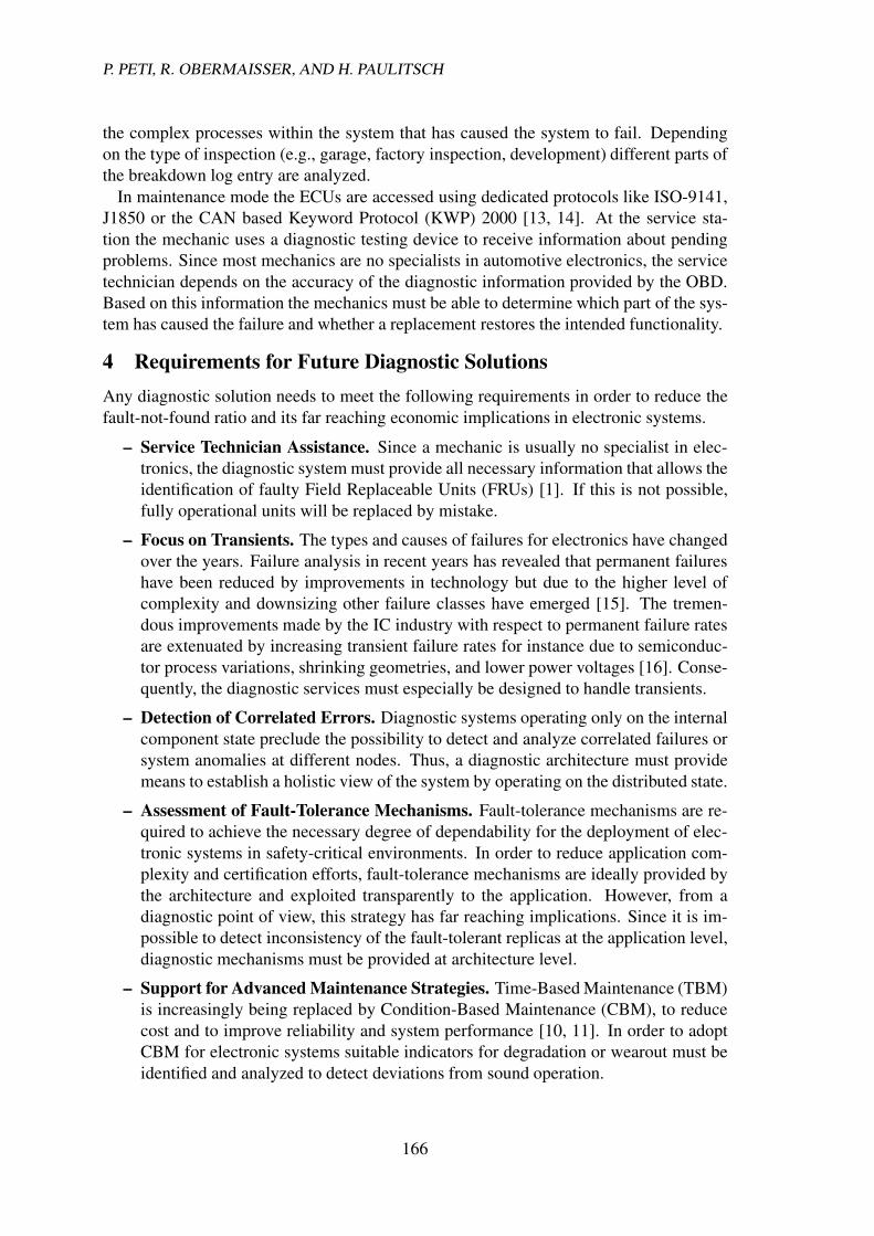
Component condition assessmentAdvanced maintenance strategies Engineering feedbackOffline analysis
Experienced faults are classfied according to a maintenance-oriented fault model into internal, external and border faults
Internal hardware faults
Random external hardware faults
Connector faults
DETECTION DISSEMINATION ANALYSIS
Figure 1: Overview of the Diagnostic Architecture
– Avoidance of the Probe Effect. Any diagnostic subsystem must avoid the introduc-tion of probe effects [17] that may forge the outcome of the diagnostic subsystem.This is especially important in case of real-time systems, where the diagnostic mes-sages must not compromise the real-time traffic in any way.
– Intellectual Property Protection. Diagnosis is often equated with revealing of in-ternal information. An integrated approach allows the realization of advanced di-agnostic strategies by solely operating on the interface state of the linking inter-faces [18] without revealing any internals of the application.
5 Overview of the Diagnostic Architecture for the PEGASUS Car
In order to cope with industrial demands on diagnosis for automotive systems an archi-tecture with integrated support for diagnosis is needed. Such an architecture provides thenecessary prerequisites to allow the effective detection, identification and classification ofexperienced errors. An integrated solution, in contrast to an addendum solution, allowsthe realization of advanced diagnostic strategies and supports the gathering of field datafor engineering feedback [4].The model of the diagnostic architecture as illustrated in Figure 1 can be divided intothree main parts, the detection of errors and anomalies on the distributed state of thesystem, the acquisition of diagnostic information via a dedicated Virtual Diagnostic Net-work (VDN), and the subsequent analysis in order to determine nature of the experiencedfault with respect to a maintenance-oriented fault model. The pivotal strategy of the diag-nostic architecture is the establishment of a holistic view on the system by operating onthe distributed state. In combination with the error containment mechanisms provided bythe TTA [19], this strategy allows tracing correlated system anomalies back to the FRUresponsible for the experienced system behavior.
5.1 The Maintenance-oriented Fault Model
As stated in [20] the concept of fault is introduced to stop the recursion of the “fault-error-failure” chain. From a maintenance point of view, we are only interested in categorizing
167
P. PETI, R. OBERMAISSER, AND H. PAULITSCH
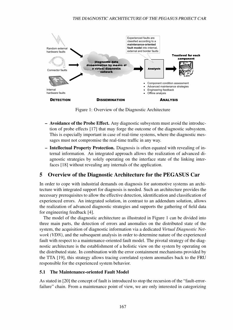
Borderline
External
Internal
Figure 2: Component Fault Model
the type of fault of the experienced failure into classes that allow a determination whethera replacement is the correct maintenance strategy. Thus, by reversing the fault-error-failure chain, it must be possible for the diagnostic subsystem to determine whether achange of a FRU can eliminate the experienced problem, or if a replacement will prove tobe ineffective.Consequently, we stop the recursion at Field Replaceable Unit (FRU) level. In thecontext of the PEGASUS car architecture in case of hardware faults the FRU is consideredto be a complete node computer. The fault classification for each FRU needs to be derivedby analyzing the prevalent types of faults affecting the given FRU.Consider for instance a crack in a Printed Circuit Board (PCB). Such a crack mayoriginate from wear-out of the material due to environmental stress, such as vibration(e.g., rough roads), shock (e.g., chuckholes, hard landings) and changes in temperature(i.e. expansion and contraction). Depending on operational conditions this crack maycause the component to fail transiently. From a maintenance point of view (at the servicestation) the first level cause – due to environmental – stress is not of interest. In analogythe exact element of the FRU that is subject to failure is of limited interest for a servicetechnician. By taking a maintenance-oriented view the most important fact we are inter-ested in is that the hardware fault can only be eliminated by replacement of the FRU. Theanalysis, which part of the FRU caused the malfunction is in the scope of the inspectionof faulty nodes at the Original Equipment Manufacturer (OEM) (and not part of the main-tenance action at the service station). For more information on the rationale behind themodel see also [21].The proposed maintenance-oriented fault model takes the component-based nature oftoday’s distributed systems into account by considering a component as a FRU for hard-ware faults. Consequently, we devise the following fault classes as illustrated in Figure 2.Faults that originate outside the component boundaries are denoted as external faults. Ex-ternal faults are characterized by having no permanent effect on the functionality of thecomponent. A restart of the component with subsequent state synchronization is a typicalstrategy to restore a correct state. An example for an external fault is ElectromagneticInterference (EMI) [22]. So-called borderline faults are the class of faults that cannot bejudged to be external or internal with respect to the component boundary. An examplefor such a fault is a connector fault (a connector consist of two parts, one attached to the
168
THE DIAGNOSTIC ARCHITECTUREOF THE PEGASUS PROJECT CAR
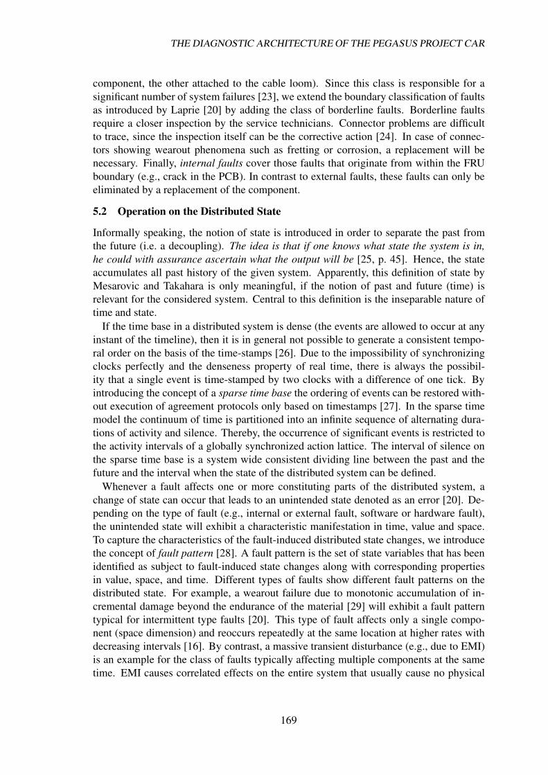
component, the other attached to the cable loom). Since this class is responsible for asignificant number of system failures [23], we extend the boundary classification of faultsas introduced by Laprie [20] by adding the class of borderline faults. Borderline faultsrequire a closer inspection by the service technicians. Connector problems are difficultto trace, since the inspection itself can be the corrective action [24]. In case of connec-tors showing wearout phenomena such as fretting or corrosion, a replacement will benecessary. Finally, internal faults cover those faults that originate from within the FRUboundary (e.g., crack in the PCB). In contrast to external faults, these faults can only beeliminated by a replacement of the component.
5.2 Operation on the Distributed State
Informally speaking, the notion of state is introduced in order to separate the past fromthe future (i.e. a decoupling). The idea is that if one knows what state the system is in,he could with assurance ascertain what the output will be [25, p. 45]. Hence, the stateaccumulates all past history of the given system. Apparently, this definition of state byMesarovic and Takahara is only meaningful, if the notion of past and future (time) isrelevant for the considered system. Central to this definition is the inseparable nature oftime and state.If the time base in a distributed system is dense (the events are allowed to occur at anyinstant of the timeline), then it is in general not possible to generate a consistent tempo-ral order on the basis of the time-stamps [26]. Due to the impossibility of synchronizingclocks perfectly and the denseness property of real time, there is always the possibil-ity that a single event is time-stamped by two clocks with a difference of one tick. Byintroducing the concept of a sparse time base the ordering of events can be restored with-out execution of agreement protocols only based on timestamps [27]. In the sparse timemodel the continuum of time is partitioned into an infinite sequence of alternating dura-tions of activity and silence. Thereby, the occurrence of significant events is restricted tothe activity intervals of a globally synchronized action lattice. The interval of silence onthe sparse time base is a system wide consistent dividing line between the past and thefuture and the interval when the state of the distributed system can be defined.Whenever a fault affects one or more constituting parts of the distributed system, achange of state can occur that leads to an unintended state denoted as an error [20]. De-pending on the type of fault (e.g., internal or external fault, software or hardware fault),the unintended state will exhibit a characteristic manifestation in time, value and space.To capture the characteristics of the fault-induced distributed state changes, we introducethe concept of fault pattern [28]. A fault pattern is the set of state variables that has beenidentified as subject to fault-induced state changes along with corresponding propertiesin value, space, and time. Different types of faults show different fault patterns on thedistributed state. For example, a wearout failure due to monotonic accumulation of in-cremental damage beyond the endurance of the material [29] will exhibit a fault patterntypical for intermittent type faults [20]. This type of fault affects only a single compo-nent (space dimension) and reoccurs repeatedly at the same location at higher rates withdecreasing intervals [16]. By contrast, a massive transient disturbance (e.g., due to EMI)is an example for the class of faults typically affecting multiple components at the sametime. EMI causes correlated effects on the entire system that usually cause no physical
169
P. PETI, R. OBERMAISSER, AND H. PAULITSCH
CNI
Host
Controller
CNI
Host
Controller
CNI
Host
Controller
CNI
Host
Controller
CNI
Host
Controller
CNI
Host
Controller
Diagnostic Unit
CNI
Host
Controller
CNI
Host
Controller
CNI
Host
Controller
CNI
Host
Controller
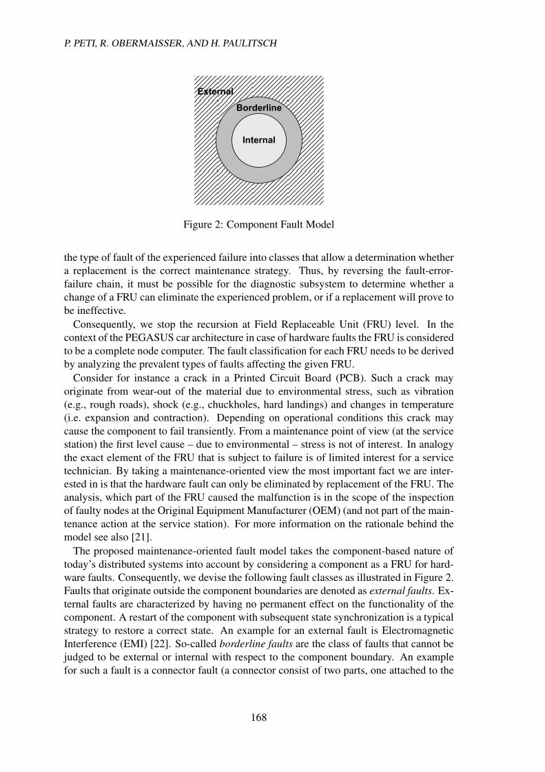
Virtual Diagnostic Network
CNI
Host
Controller
Virtual Diagnostic Network
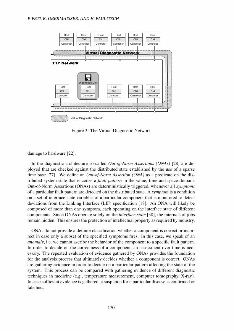
Figure 3: The Virtual Diagnostic Network
damage to hardware [22].
In the diagnostic architecture so-called Out-of-Norm Assertions (ONAs) [28] are de-ployed that are checked against the distributed state established by the use of a sparsetime base [27]. We define an Out-of-Norm Assertion (ONA) as a predicate on the dis-tributed system state that encodes a fault pattern in the value, time and space domain.Out-of-Norm Assertions (ONAs) are deterministically triggered, whenever all symptomsof a particular fault pattern are detected on the distributed state. A symptom is a conditionon a set of interface state variables of a particular component that is monitored to detectdeviations from the Linking Interface (LIF) specification [18]. An ONA will likely becomposed of more than one symptom, each operating on the interface state of differentcomponents. Since ONAs operate solely on the interface state [30], the internals of jobsremain hidden. This ensures the protection of intellectual property as required by industry.
ONAs do not provide a definite classification whether a component is correct or incor-rect in case only a subset of the specified symptoms fires. In this case, we speak of ananomaly, i.e. we cannot ascribe the behavior of the component to a specific fault pattern.In order to decide on the correctness of a component, an assessment over time is nec-essary. The repeated evaluation of evidence gathered by ONAs provides the foundationfor the analysis process that ultimately decides whether a component is correct. ONAsare gathering evidence in order to decide on a particular pattern affecting the state of thesystem. This process can be compared with gathering evidence of different diagnostictechniques in medicine (e.g., temperature measurement, computer tomography, X-ray).In case sufficient evidence is gathered, a suspicion for a particular disease is confirmed orfalsified.
170

THE DIAGNOSTIC ARCHITECTUREOF THE PEGASUS PROJECT CAR
Time
Action Lattice
Anomalies
...
...
...
ONAAssessmentTrajectories(A,B)
A B
Figure 4: Assessment Process
5.3 Dissemination of Diagnostic Information
The acquisition and dissemination of diagnostic information occurs through high-levelarchitectural services. By exploiting these services, a so-called Virtual Diagnostic Net-work (VDN) is established. A virtual network is an overlay network that is established ontop of a physical network [31]. In the PEGASUS system architecture, we provide a vir-tual network on top of the time-triggered core communication service provided by TTP.This virtual network is tailored to the requirements of the diagnostic subsystem via theprovided functionality, the operational properties, the namespace, and the dependabilityproperties.Furthermore, this virtual network is encapsulated so that communication activities areneither visible nor have any effect (e.g., performance penalty) on the exchange of mes-sages for the dynamic four-wheel-drive in the time-triggered network. Figure 3 illustratesthis system architecture. By using only elementary interfaces [32] to establish the virtualdiagnostic network, no back-propagation of the diagnostic dissemination service to theapplication subsystem controlling the car dynamics is possible. This way, the diagnosticarchitecture need not be validated to the dependability of the highest application criticalityclass.Such a virtual solution has twomain advantages. At first, real-time traffic is not compro-mised in any way since the bandwidth for the exchange of diagnostic information is fixeda priori at design time. This way a deterministic message exchange for all non-diagnosticsubsystems is guaranteed. Secondly, the purely virtual solution ensures that no additionalhardware faults are introduced due to wiring or connector problems. Consequently, noprobe effect can be introduced [17].
5.4 Analysis
The analysis subsystem executes algorithms on the gathered diagnostic information in or-der to assess the condition of each component. By taking a maintenance-oriented faultmodel (see Section 5.1) as the basis for the assessment process, the ultimate goal of the
171

P. PETI, R. OBERMAISSER, AND H. PAULITSCH
analysis is to decide whether a FRU (as the smallest replaceable unit with respect to main-tenance) should be replaced or remain in the given system. Therefore, the maintenance-oriented fault model defines a classification of faults into internal (e.g., crack in PCB),borderline (e.g., connector failure) or external (e.g., EMI).
The evaluation process performed by the diagnostic subsystem is illustrated in Figure 4.The evaluation process is based on a consistent notion of state, which is provided throughthe action lattice of the sparse time base established by the core services. The arrowsin Figure 4 indicate the assessment trajectories. At first both arrows show componentconformance with the specification, i.e. correct interface states. As time progresses arrowA exhibits an increasing confidence for a violation of the specification, while arrow Bindicates a component behavior in accordance with the specified service.
As a result of the diagnostic algorithms, a trust level for each replaceable componentof the system is determined that forms the basis for decision-making process of the main-tenance engineer. Thus, the system itself analyzes its current condition and informs theservice technician about the current health status. This diagnostic infrastructure supportsthe realization of advanced maintenance strategies such as CBM [10] to be employed inthe context of electronic systems.
6 Conclusion
In the scope of the PEGASUS project a series production vehicle is equipped with a TTPnetwork to realize advanced powertrain functionality in order to improve driving com-fort and the handling of the car in critical situations. The use of the Time-TriggeredArchitecture (TTA) as the communication infrastructure excels not only with dependabil-ity and composability properties in comparison with today’s used technology but alsoallows investigating and implementing new maintenance strategies. Since the introduc-tion of X-by-wire systems requires new diagnostic concepts to improve capabilities andeffectiveness, the field data that will be derived from the experiences gained with a seriesproduction car will have significant impact on effective maintenance solutions.
In order to cope with new diagnostic demands of on-board diagnostic subsystems thedesign for diagnosis principle must be obeyed when designing new architectures. Ad-hoc solutions that treat diagnosis as an addendum rather than an integrated part of everysystem are no longer applicable. By following this principle the introduced diagnostic ar-chitecture is designed to reduce the fault-not-found ratio that is currently causing negativemedia coverage indicating electrical problems as number one reason for car breakdown.By operating on the distributed state of the system a holistic view on the system can beestablished that allows correlation of experienced failures. Since the majority of today’sECU failures are transient, only an online analysis service is capable of answering thequestion whether the replacement of a particular ECU will prove to be effective. Anaccurate diagnosis with short repair time is a prerequisite for binding a customer to themanufacturer.
Future fault injection campaigns will provide interesting data on the effectiveness ofthe deployed architecture and give important feedback for the implementation of accurateanalysis algorithms.
172

THE DIAGNOSTIC ARCHITECTUREOF THE PEGASUS PROJECT CAR
Acknowledgments
This work has been supported in part by the Austrian Advanced Automotive Technology Projectunder project No. 809437 and the European IST project ARTIST2 under project No. IST-004527and the European IST project DECOS under project No. IST-511764.
References[1] G. Leen and D. Heffernan. Expanding automotive electronic systems. Computer, 35(1):88–93,January 2002.
[2] The Hansen Report on Automotive Electronics, November 2002. Portsmouth NH USA, www.hansenreport.com.
[3] Robert Bosch Gmbh, Stuttgart, Germany. CAN Specification, Version 2.0, 1991.
[4] M. Sachenbacher, P. Struss, and R. Weber. Advances in design and implementation of OBD functionsfor diesel injection based on a qualitative approach to diagnosis. In Proceedings of SAE 2000 WorldCongress, Detroit, MI, USA, 2000. SAE.
[5] J. Barkai. Vehicle diagnostics–are you ready for the challenge? In Proceedings of Automotive &Transportation Technology (ATT) Congress & Exhibition, volume 5. SAE, October 2001.
[6] E. Bretz. By-wire cars turn the corner. IEEE Spectrum, 38(4):68–73, April 2001.
[7] H. Kopetz and G. Bauer. The time-triggered architecture. IEEE Special Issue on Modeling andDesign of Embedded Software, January 2003.
[8] H. Kopetz. Specification of the TTP/C Protocol. TTTech, Schonbrunner Straße 7, A-1040 Vienna,Austria, July 1999. Available at http://www.ttpforum.org.
[9] D.A. Thomas, K. Ayers, and M. Pecht. The ’trouble not identified’ phenomenon in automotiveelectronics. Microelectronics Reliability, 42:641–651, 2002.
[10] V. Polimac and J. Polimac. Assessment of present maintenance practices and future trends. InProceedings of the Transmission andDistribution Conference and Exposition, IEEE/PES, pages 891–894, 2001.
[11] C. Teal and D. Sorensen. Condition based maintenance [aircraft wiring]. In Proceedings of the 20thConference on Digital Avionics Systems, DASC, volume 1, pages 3B2/1–3B2/7, October 2001.
[12] H. Kopetz. Fault containment and error detection in the time-triggered architecture. In Proceedingsof the International Symposium on Autonomous Decentralized Systems, Pisa, Italy, April 2003.
[13] W. Waldeck. Diagnostic protocol challenges in a global environment. In Convergence InternationalCongress & Exposition On Transportation Electronics, Detroit, MI, USA, October 2002. SAE.
[14] International Organization for Standardization. Keyword Protocol 2000, ISO 14230, 1999.
[15] M. Pecht and V. Ramappan. Are components still the major problem: a review of electronic systemand device field failure returns. IEEE Transactions on Components, Hybrids, and ManufacturingTechnology, 15(6):1160–1164, December 1992.
[16] C. Constantinescu. Impact of deep submicron technology on dependability of VLSI circuits. InProceedings of the International Conference on Dependable Systems and Networks, pages 205–209.IEEE, 2002.
[17] J. Gait. A probe effect in concurrent programs. Software Practice and Experience, 16(3):225–233,March 1986.
[18] H. Kopetz and N. Suri. Compositional design of RT systems: A conceptual basis for specificationof linking interfaces. In Proceedings of Sixth IEEE International Symposium on Object-OrientedReal-Time Distributed Computing, pages 51–60, May 2003.
[19] H. Kopetz. Fault containment and error detection in the time-triggered architecture. In Proceedingsof the Sixth International Symposium on Autonomous Decentralized Systems, April 2003.
173

P. PETI, R. OBERMAISSER, AND H. PAULITSCH
[20] A. Avizienis, J.C. Laprie, and B. Randell. Fundamental concepts of dependability. Research Report01-145, LAAS-CNRS, Toulouse, France, April 2001.
[21] P. Peti, R. Obermaisser, and H. Kopetz. A maintenance-oriented fault model for the DECOS inte-grated diagnostic architecture. In Proceedings of the Workshop on Parallel and Distributed Real-TimeSystems 2005 (WPDRTS). IEEE, April 2005.
[22] H. Kim, A.L. White, and K.G. Shin. Effects of electromagnetic interference on controller-computerupsets and system stability. IEEE Transactions on Control Systems Technology, 8(2):351–357,March2000.
[23] J. Swingler, J.W. McBride, and C. Maul. Degradation of road tested automotive connectors. IEEETransactions on Components and Packaging Technologies, 23(1):157–164,March 2000.
[24] K. Kimseng, M. Hoit, N. Tiwari, and M. Pecht. Physics-of-failure assessment of a cruise controlmodule. Microelectronics Reliability, 39:1423–1444, 1999.
[25] M. D. Mesarovic and Y. Takahara. Abstract Systems Theory, chapter 3. Springer-Verlag, 1989.
[26] H. Kopetz. Real-Time Systems, Design Principles for Distributed Embedded Applications. KluwerAcademic Publishers, Boston, Dordrecht, London, 1997.
[27] H. Kopetz. Sparse time versus dense time in distributed real-time systems. In Proceedings of 12thInternational Conference on Distributed Computing Systems, Japan, June 1992.
[28] P. Peti, R. Obermaisser, and H. Kopetz. Out-of-norm assertions. In Proceedings of the 11th IEEEReal-Time and Embedded Technology and Applications Symposium (RTAS). IEEE, March 2005.
[29] A. Ramakrishnan. The Avionics Handbook, chapter Electronic Hardware Reliability. CRC PressLCC, 2001.
[30] M.-C. Gaudel, V. Issarny, C. Jones, H. Kopetz, E. Marsden, N. Moffat, M. Paulitsch, D. Powell,B. Randell, A. Romanovsky, R. Stroud, and F. Taiani. Final version of the DSoS conceptual model.DSoS Project (IST-1999-11585) Deliverable CSDA1, December 2002. Available as Research Report54/2002 at http://www.vmars.tuwien.ac.at.
[31] R. Obermaisser. Event-Triggered and Time-Triggered Control Paradigms – An Integrated Architec-ture. Real-Time Systems Series. Kluwer Academic Publishers, November 2004.
[32] H. Kopetz. Elementary versus composite interfaces in distributed real-time systems. In Proceedingsof ISADS’99, Tokyo, Japan, March 1999.
174