Embed Size (px)
Citation preview

2
The Development of an Autonomous Library Assistant Service Robot
Julie Behan Digital Health Group, Intel,
University of Limerick, Limerick, Ireland
1. Introduction
In modern society, service robots are becoming increasingly integrated into the lives of ordinary people. This is primarily due to the fact that the world is becoming an aged society (a society in which 10% of the population is over 60 years of age). Service robots may provide support to this increasing pool of aged individuals in a variety of forms, such as social interaction robots (Bruce et al., 2001; Breazeal 2002; Fong et al., 2003), task manipulation in rehabilitation robotics (Casals et al., 1993; Bolmsjo et al., 1995; Dario et al., 1995) and through assistive functionality such as nurse bots, tour guide robots etc (Evans 1994; Thrun et al., 2000; Graf et al., 2004). This chapter describes the development of an autonomous service robotic assistant known as “LUCAS”: Limerick University Computerized Assistive System, whose functionality includes the assistance of individuals within a library environment. The robot is described in this role through environment interaction, user interaction and integrated functionality. The robot acts as a guide for users within the library to locate user specific textbooks. A complete autonomous system has been implemented, which allows for simple user interaction to initiate functionality and is described specifically in terms of its implemented localization system and its human–robot interaction system. When evaluating the overall success of a service robot, three important factors need to be considered: 1. A successful service robot must have complete autonomous capabilities. 2. It must initiate meaningful social interaction with the user and 3. It must be successful in its task. To address these issues, factors 1 and 3 are grouped together and described with respect to the localization algorithm implemented for the application. The goal of the proposed localization system is to implement a low cost accurate navigation system to be applied to a real world environment. Due to cost constraints, the sensors used were limited to odometry, sonar and monocular vision. The implementation of the three sensor models ensures that a two dimensional constraint is provided for the position of the robot as well as the orientation. The localization system described here implements a fused mixture of existing localization techniques, incorporating landmark based recognition, applied to a unique setting. In classical approaches to landmark based pose determination, two distinguished interrelated problems are identified. The first is the correspondence problem, which is concerned with finding pairs of corresponding landmark and image features. The
www.intechopen.com

Service Robots
28
second stage is the pose problem, which consists of finding the 3D camera coordinates with respect to the origin of the world model given the pair of corresponding features. Within the described approach, rather than extracting features and creating a comparison to environment models as described in the correspondence problem, the features within the image are fitted to known environment landmarks at that estimated position. This can be achieved due to the regularity of common landmarks (bookshelves) within the environment. The landmark features of interest, which consist of bookshelves, are recognized primarily through the extraction of vertical and horizontal line segments which may be reliably manipulated even under changing illumination conditions. The method proposes a simple direct fitting of line segments from the image to the expected features from the environment using a number of techniques. Once the features in the image are fitted to the environment model the robot’s pose may then be calculated. This is achieved through the fusion of validated sonar data, through an application of the Extended Kalman Filter, and the matched environment features. The results section for the given localization technique shows the level of accuracy and robustness achievable using fusion of simplistic sensors and limited image manipulation techniques within a real life dynamic environment. The second factor, which is used to evaluate the success of a service robot is its ability to interact meaningfully with its users. Through the development and implementation of existing service robotic systems within real time public dynamic environments, researchers have realised that several design principles need to be implemented for a robotic application to be a success. From existing literature, within the field of service and assistive robotics, these principles have been categorised into eight major topics. To incorporate the essential design principles one of the most important aspects in the creation of a successful assistant robot is the human-robot interaction system. To achieve successful human-robot interaction, between “LUCAS” and the user, a graphical interface displaying a human-like animated character was implemented. The software used in the creation of the character is known as the Rapid Application Developer (RAD), and is part of the CSLU toolkit created by the Oregon Health & Science University (OHSU) Centre for Spoken Language (RAD 2005). The implementation of the RAD, as well as the supported functionality of the robot, allows for the critical design principles to be implemented, helping to ensure that the robotic application may be successfully applied to a real life environment. The remainder of this chapter is divided into the following topics: Section 2 discusses the introduction of service robots and their applications. Section 3 describes the implemented localization system. Section 4 details the main design requirements for a successful service robot, in terms of human-robot interaction and usability, and how they are applied to “LUCAS”. Finally Section 5 discusses the overall implementation and successful application of the robot.
2. Why service robots?
According to the United Nations Population Division the number of elderly people is increasing dramatically in modern day society (U.N. 2004), for example, in Ireland it is predicted that by the year 2050, the number of people aged 65+ will be 24% of the total population (today 11.4%) and the number of people aged 80+ will be 6.4% (today 1.3%). This trend is being experienced world wide and is known as “greying population” (U.N. 2004). If we follow disability trends associated with ageing, we can predict that in this new modern society 16% or more of these persons over the age of 65 will be living with one or more impairments that disrupt their ability to complete activities of daily living in their homes
www.intechopen.com
The Development of an Autonomous Library Assistant Service Robot
29
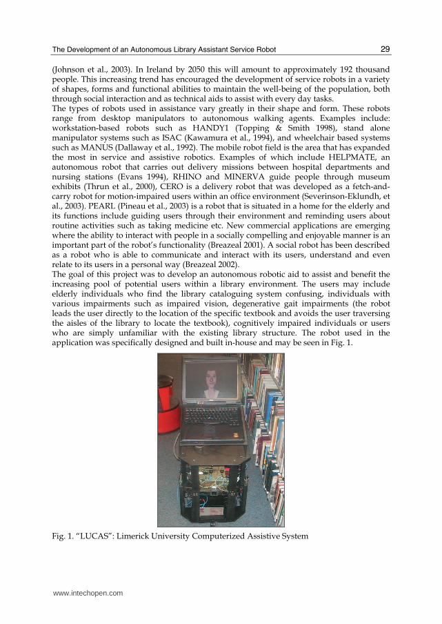
(Johnson et al., 2003). In Ireland by 2050 this will amount to approximately 192 thousand people. This increasing trend has encouraged the development of service robots in a variety of shapes, forms and functional abilities to maintain the well-being of the population, both through social interaction and as technical aids to assist with every day tasks. The types of robots used in assistance vary greatly in their shape and form. These robots range from desktop manipulators to autonomous walking agents. Examples include: workstation-based robots such as HANDY1 (Topping & Smith 1998), stand alone manipulator systems such as ISAC (Kawamura et al., 1994), and wheelchair based systems such as MANUS (Dallaway et al., 1992). The mobile robot field is the area that has expanded the most in service and assistive robotics. Examples of which include HELPMATE, an autonomous robot that carries out delivery missions between hospital departments and nursing stations (Evans 1994), RHINO and MINERVA guide people through museum exhibits (Thrun et al., 2000), CERO is a delivery robot that was developed as a fetch-and-carry robot for motion-impaired users within an office environment (Severinson-Eklundh, et al., 2003). PEARL (Pineau et al., 2003) is a robot that is situated in a home for the elderly and its functions include guiding users through their environment and reminding users about routine activities such as taking medicine etc. New commercial applications are emerging where the ability to interact with people in a socially compelling and enjoyable manner is an important part of the robot’s functionality (Breazeal 2001). A social robot has been described as a robot who is able to communicate and interact with its users, understand and even relate to its users in a personal way (Breazeal 2002). The goal of this project was to develop an autonomous robotic aid to assist and benefit the increasing pool of potential users within a library environment. The users may include elderly individuals who find the library cataloguing system confusing, individuals with various impairments such as impaired vision, degenerative gait impairments (the robot leads the user directly to the location of the specific textbook and avoids the user traversing the aisles of the library to locate the textbook), cognitively impaired individuals or users who are simply unfamiliar with the existing library structure. The robot used in the application was specifically designed and built in-house and may be seen in Fig. 1.
Fig. 1. “LUCAS”: Limerick University Computerized Assistive System
www.intechopen.com

Service Robots
30
3. Localization
In literature there are three main methods to solve the problem of localization. The first is map-based approaches where the robot makes use of a user created geometric or topological model of the environment, which is usually referred to as an “occupancy map”. The second approach is map-building based, where the robot uses its sensors to create geometric or topological models of the environment and then use these models for navigation. The third approach is map-less navigation where the robot has no explicit representation of the environment but relies on object recognition or object tracking to aid navigation. For indoor environments the map-based approach is the most common technique used due to the structured nature of the environment. In (Pérez et al., 1999), Pérez et al. describe the basic idea of localization within a mapped environment through the following method: At each location of the robot trajectory the localization system perceives the environment with some sensing device. This sensorial information is compared with the expected values (predicted from an a priori map), and used to correct the available robot location, to make the perceived data match better with the expected data. The localization system described here is based on Pérez’s essential elements to create an accurate and robust localization process using minimalist sensors and processing time, while maintaining reliable accuracy. For a real world application setting, a cost effective solution is essential for universal acceptance and deployment. “LUCAS” was designed to be low cost with its dependence being on basic sensor fusion including calibrated odometry, sonar and monocular vision. As literature has shown, a more precise estimation of the localization parameters may be provided through the fusion of multiple data sources. The authors believe that instead of relying on complex geometric measurements, even with more basic information, a proper combination of different sources can achieve accurate localization. The localization system makes use of the environment features (landmarks), which primarily consist of rows of bookshelves. Horizontal or vertical edges occur frequently in man made environments, which are generally parallelepiped in nature. These edges provide essential information regarding the environment and are generally noted for their simplicity in extraction. The localization system provides an accurate and complete solution, for the specific environment, using low cost off-the-shelf sensing devices. The method proposed is a continuous localization process rather than a single localization step so odometry errors do not have time to accumulate. This allows the robot to apply individual localization procedures for specific localization regions based on odometry alone. The localization system is implemented in a three stage approach. The first stage occurs when the robot is navigating in the y world direction, while the robot is locating the correct bookshelf row. The procedure implemented involves initial position estimation from odometry, fused with vertical feature extraction from real time processed images. The output of which is augmented with sonar data that is validated through the use of an Extended Kalman Filter (Welch & Bishop 2004). The second stage occurs on the transition in navigation between the x world and y world directions and is applied when the robot reaches the aisle it needs to traverse. This localization stage incorporates horizontal feature extraction from real time processed images, using calculated vanishing points for orientation information. Finally the third stage occurs when the robot is traversing the bookshelf aisle, to locate the desired textbook, and motion is in the direction of the x world axis. This final stage involves a sonar and odometry data implementation to accurately reach the desired goal location. The locations of the individual localization stages within an environment map may be seen in Fig. 2.
www.intechopen.com

The Development of an Autonomous Library Assistant Service Robot
31
Book Shelf
Book Shelf
Book Shelf
Book Shelf
Seating Area
Computer
Catalogue
X World
Robot Starting
PoseLocalization
Stage 1Localization
Stage 2Localization
Stage 3
Key
Fig. 2. Environment representation with localization stages
3.4 The implemented localization process
To sense the environment the robot has a suite of nine sonar transducers embedded uniformly as seen in Fig. 3. The robot has two driving wheels and two omni-directional balancing wheels. The origin of the mobile robot’s coordinate frame is set at the midpoint between the two driving wheels. As well as using sonar data, a low resolution monocular camera, which points towards the environment features of interest (perpendicular to the direction of motion of the robot), is also used for the localization system. The camera is centrally positioned between sonar sensors seven and eight (Fig. 3 ). The low resolution of
Fig. 3. Robot Sensor System
352 x 288 pixels provides sufficient quality to extract the desired features while reducing the execution time of the image processing algorithms. As the camera coordinate system was chosen to be the same as the world coordinate system and due to the fact that the camera is placed perpendicular to the direction of motion of the robot, the xr axis coincides with the optical axis and points towards the scene. The image plane is parallel to the (yr, zr) plane and
www.intechopen.com

Service Robots
32
is displaced a distance f along the xr axis. The position and orientation of the robot at time step k is represented by the state vector X(k) = (xr(k), yr(k), θr(k))T, which corresponds to a cartesian location (x, y) and a heading defined with respect to a global coordinate frame θ at the kth sampling time. A description of how the vehicles position X(k) changes with time in response to a control input u(k) and a noise disturbance w(k) is known as the Plant Model (Leonard & Durrant-White 1992). The noise source is assumed to have zero mean with a covariance of Q(k). The control input is defined by a translation forward through the distance T(k) followed by an anti-clockwise rotation through the z axis Δθ(k) and is expressed as:
[ ])(),()( kkTku θΔ= (1)
Assuming the pose of the robot at the (k-1)th sampling time is known, the state vector at the kth sampling time is defined as the state transition function f(X(k-1),u(k)) plus the noise variable w(k) and is expressed as follows:
)())(),1(()( kwkukXfkX +−= (2)
or
)(
)()1(
))1(sin()()1(
))1(cos()()1(
)( kw
kk
kkTky
kkTkx
kX
r
rr
rr +⎥⎥⎥⎦
⎤⎢⎢⎢⎣
⎡Δ+−
−+−−+−
=θθθθ
(3)
In this particular application the control input was limited to combinations of three distinct positional movements; a forward motion and 90° left and right turns As the two driving wheels are driven by two independently controlled D.C. motors an additional variable was added to the system state equation Δδ, which is used to compensate for the variability of the individual motors i.e. drift compensation. For this particular application the drift parameter was estimated due to observations of the robot’s movement. An adequate drift parameter is quiet difficult to calculate accurately, particularly due to the fact that the two motors are driven independently by two individual power sources. Also different environment floor textures result in different variability in the wheel rotation, i.e. a carpeted floor caused more resistance than a tiled floor. The system state equation now becomes:
⎥⎥⎥⎦
⎤⎢⎢⎢⎣
⎡Δ+Δ+−
Δ+−+−Δ+−+−
=))(()1(
))1(sin()()1(
))1(cos()()1(
)(
δθθδθδθ
kk
kkTky
kkTkx
kX
r
rr
rr (4)
Using Eqn. 4 the drive system is said to be calibrated. According to DeSouza (DeSouza & Kak 2002), it is imperative, either implicitly or explicitly, for a vision system meant for navigation to have a predefined definition of what the camera is supposed to see. After each positional movement, using the a priori map augmented with an odometry position estimation, the robot has a preconceived estimate of where it is positioned within the environment. This position estimation is prone to error especially due to drift and wheel slippage. Within the localization procedure, firstly, the robot approximately locates the landmarks using basic odometry. It then determines its exact
www.intechopen.com

The Development of an Autonomous Library Assistant Service Robot
33
position relative to the landmark using a method of observation of vertical or horizontal edges or vanishing points depending on its current pose within the environment. The robot’s pose relative to the landmark is extracted using a method of data fusion based on ultrasonic sector scans and image data. The robot’s actual pose must be within a solution region, which relates to the individual landmark for localization to be accurately determined. Due to this fact the method of localization occurs approximately every 150cm of movement to ensure that the robot’s actual position is always within a solution region and does not allow odometry errors to accumulate. The robot is determined to be within a localization region by the presence of dominant oblique and vertical lines within the cameras field of view. The position of these lines, together with fused sonar data, indicates the robot’s current position. Observation of a particular landmark within a localization region is used to correct the robot’s pose relative to the landmark. An implementation of the Extended Kalman Filter (EKF) is used to validate the observational sensor values before corrective pose procedures occur. Due to the predictability of the environment and validation through the EKF a single observation is sufficient to determine the robot’s pose at each localization region. The localization method is a continuous process carried out throughout the robot’s trajectory and is initiated once the robot reaches the first localization region (as predicated by the a priori map and the A* algorithm), indicated initially by odometry. The robot’s configuration space is divided into localization regions, which are determined by the presence of identifiable features within the environment. As the robot manoeuvres to its goal location, it passes a sequence of landmarks, which primarily consist of rows of bookshelves. Fig. 4, shows an example of the sequence of bookshelves the robot would see as it traverses the library aisles. When odometry determines the robot has reached the first row of bookshelves along its path (based on a priori map), the localization process begins and an image is processed from the robot’s current location. As the robot progresses through the environment the position of the dominant vertical lines within the image indicate its current position. In Fig. 4 (iii), two dominant bookshelf edges are present telling us that the robot is located directly adjacent the end of a particular bookshelf row. In Fig. 4 (ii) and (iv) a single dominant line is present, indicating that the robot is positioned between the aisle in-between two bookshelf rows and the end of a bookshelf row or vice versa. In Fig. 4 (i), no dominant vertical lines appear indicating the robot is situated perpendicular to the aisle in-between two bookshelf rows. A classic four step approach has been implemented for the image based localization. 1. Image acquisition: an image is obtained when odometry measurements determine the robot is in the vicinity of a landmark of interest. 2. Image feature extraction: the image is first processed to enable high quality feature extraction. The Sobel operator is applied to a high thresholded binary image to extract dominant vertical or horizontal edge segments. Once the image edges are obtained, a simple connected component algorithm is used to form distinct line segments. 3: Feature manipulation: as previously stated the extracted line segments are fitted to known environment features at the robot’s estimated position. Within the first localization stage bookshelf edges are the features that are required, so only dominant vertical lines, which are representative of a bookshelf edge, are obtained from the image. The localization method proposes a simple direct fitting of extracted line segments from the image to the estimated feature representation of the environment using a number of techniques. Firstly line segments that do not exceed a minimum length are eliminated. A technique of grouping together split line segments if they are within a threshold vicinity and orientation angle
www.intechopen.com

Service Robots
34
apart is then implemented. The total length value of grouped lines is examined to ensure that the extracted elements represent an environment variable of interest. As the position of environment landmarks is fixed and the availability of traversable space for the robot is limited the extracted features of interest must also adhere to this restriction. For example, extracted features of interest cannot be within close proximity to each other. The remaining extracted lines are then grouped by the algorithm to determine if suitable as a feature of interest. The modification of the extracted line segments allows for the environment features to be accurately modelled within the image, which results in the variance associated with the robot’s current pose to be reduced to zero.
(i)
(ii)
(iii)
(iv)
Fig. 4. Sequence of bookshelves
The final step in the localization process is 4: Camera pose computation: as the cameras pose is
fixed relevant (perpendicular) to the robot pose, the information obtained directly from the
image is used to calculate the robot’s pose. If two dominant bookshelf edges have been
obtained as in Fig. 4(iii), the yr coordinate may be determined (y coordinate of bookshelf +/-
non-centre error of bookshelf within image) and xr and θr, may be obtained using
transmission pulses from the ultrasonic suite of sensors. Two ultrasonic sensors lie
uniformly at either side of the camera and as only a single sector scan is used to determine
the metric environment measurements at each localization stage, the success of the complete
system lies on the accuracy of the readings. In literature sonar has been known to be prone
to reflections and false detection. To reduce the probability of erroneous readings, a
www.intechopen.com

The Development of an Autonomous Library Assistant Service Robot
35
validation method incorporating an Extended Kalman Filter (EKF) was utilized. The
Kalman filter is a recursive data processing solution to the discrete-data linear filtering
problem (Welch & Bishop 2004). It processes all available measurements regardless of their
precision, to estimate the current value of the variables of interest, with use of the complete a
priori knowledge of the system and measurement devices. This includes initial conditions,
the statistical description of the system noises, measurement errors and uncertainties in the
dynamic model. The output estimate determines the desired variables in such a manner that
the error is minimized statistically. The recursive nature means that the Kalman filter does
not require all previous data to be kept in storage and reprocessed every time a new
measurement is taken. The Kalman Filter is adapted to the non-linear case through the use
of the Extended Kalman Filter (EKF) which obtains a suboptimal estimation, using a linear
approximation of the system equations.
The EKF relies on two models: a plant model with its associated variance and a measurement model. The plant model is expressed as:
)())(,ˆ(ˆ1/11/ kwkuXfX kkkk += −−− . (5)
1/ˆ −kkX is expressed as the predicted robot location at time step k based on k-1 sensor
observations. The zero mean Gaussian noise associated with the plant model is described through w(k) with covariance Q(k). The variance of this prediction is defined as:
)(1/11/ kQffPP T
kkkk +∇∇= −−− (6)
f∇ is the Jacobian of the state transition function, ))(,ˆ( 1/1 kuXf kk −− ,and is obtained by
linearizing about the updated state estimate )ˆ( 1/1 −− kkX (Leonard & Durrant-White 1992).
⎥⎥⎥⎦
⎤⎢⎢⎢⎣
⎡ −=∇ −−
−−
100
)ˆ)(cos(10
)ˆ)(sin(01
1/1
1/1
kk
kk
kT
kT
f θθ
(7)
The measurement model makes explicit the information provided by a sensor measurement
in terms of the current vehicle position (1/
ˆ −kkX ) and the position of geometric features in the
environment, with an estimate of measurement noise (Leonard & Durrant-White 1992). It is used to generate predicted observations of each target from the predicted location of each sensor. The measurement function, ),ˆ( 1/ tXH kki st − , expresses a predicted observation )(ˆ kzi
from
sensor s to target t, as a function of the predicted vehicle position 1/
ˆ −kkX and the target
geometry:
)(),ˆ()(ˆ1/ kvtXHkz kkii st += − (8)
where the observation noise measurement is approximated by v(k).
www.intechopen.com

Service Robots
36
As previously stated each localization target consists of rows of bookshelves which may be expressed as line segments in a 2D representation environment. According to (Leonard & Durrant-White 1992; Meng Quing-Hao et al. 2000), the distance between the jth (j = 1..9) sonar and the ith line segment may be expressed as:
)sin()()cos()( oijoiji kykxDsegHseg θθ −−= (9)
where:
),( jj yx are the global coordinates of the jth sonar sensor
Dseg is the distance from the global yworld axis to the ith line segment θoi is the angle with respect to the xworld axis of a perpendicular drawn from the ith line segment to the origin. As all the landmarks of interest lie parallel to the xworld axis, θoi becomes zero. The environment coordinate system with world and robot axis may be seen in Fig. 5.
The global predicted orientation ˆ ( )j
kα of the jth sonar sensor is used to modify the predicted
Hsegi observation representation of the ith line segment in order to find a true expression of the approximated distance between the jth sensor and the ith line segment. The new approximation becomes:
))(ˆcos(/_ kHsegtrueHseg jii α= (10)
Fig. 5, graphically displays the difference between the Hsegi observation representation and the true observation Hsegi_truei., as well as the robot’s pose at individual time steps.
The predicted state estimate 1/
ˆ −kkX is used to compute the measurement Jacobian
itrueHseg _∇ for each prediction, which after some mathematical expansion is expressed as:
T
oikkjoikkj
oi
oi
i
yx
trueHseg
⎥⎥⎥⎦
⎤⎢⎢⎢⎣
⎡−−−
−−
=∇−− )ˆcos(')ˆsin('
sin
cos
_
1/1/ θθθθθθ
(11)
Once an actual observation, )(kz j , is obtained from the sonar sensors a matching process
is required between the predicted and actual measurements at each sampling time. For each sonar sensor the innovation variable may be defined as:
)(ˆ),ˆ()()(
)(ˆ)()(
1/ kvtXHkzkE
kzkzkE
ikkijij
ijij
st +−=−=
− (12)
where )(ˆ kvi is the estimated expectation of observation noise.
If the prediction and observation do not correspond to the same sonar sensor the innovation is set to infinity. The innovation covariance is expressed as:
)(ˆ__))(var()( 1/ kRtrueHsegPtrueHsegkEkS T
ikkiijij +∇∇== − (13)
where )(ˆ kR is the estimated expected variance of the observation noise )(ˆ kvi
www.intechopen.com

The Development of an Autonomous Library Assistant Service Robot
37
Fig. 5. Environment and Robot Variables at Different Time Steps
If individual sonar readings do not pass through a validation gate, the pose update may be
updated using a combination of real readings and estimated readings obtained from the
output of the EKF. The xr coordinate is determined from the average distance reading of the
two sensors while the orientation of the robot (θr) is determined from the difference between
the two readings. If only one vertical line is determined from the image as in Fig. 4(ii) and
(iv), the position of the single dominant edge within the image provides essential
information about how far the robot is from the centre aisle between the two rows of
bookshelves. Using a procedure known as perspective projection, which is approximated by
the pinhole camera model, points in the image plane may be mapped to the object plane
using simple geometry. Using the pinhole camera model, the distance from the extracted
bookshelf edge to the image edge as seen in Fig. 6, may be calculated, which is used to
determine the yr coordinate for the current position.
www.intechopen.com

Service Robots
38
Fig. 6. Single extracted bookshelf edge
The remaining coordinates xr and θr may be established as before if the detected bookshelf
edge lies within the overlap detection region of the adjacent ultrasonic sensors. Both
ultrasonic sensors are arranged so that their combined field of view approximately equals
the cameras field of view. As both sensor ranges are approximately the same, the position of
the bookshelf edge within the image allows us to determine whether the actual bookshelf
edge lies in the field of view of both ultrasonic sensors. If both ultrasonic sensors may be
used accurately xr may be determined by the average of the two readings while θr may be
calculated using the discrepancies between the two readings. If the bookshelf edge can only
be accurately measured by a single ultrasonic sensor, which falls within the EKF validation
gate, then the remaining localization parameters are updated using a combination of real
and predicted data. The Extended Kalman Filter implementation ensures that a single sonar
sector scan is efficient to obtain accurate metric environment information as the
measurements are validated, ensuring accuracy, before being passed to the motion control
module.
This process of localization continues until the robot reaches the aisle that it has to traverse
to obtain the specific textbook. On the last forward positional movement the robot locates
itself in-between the rows of bookshelves containing the desired textbook. At this point, the
second stage within the localization technique is utilized, which incorporates a technique
known as vanishing point detection. With vanishing points, the relationship between 2D
line segments in the image plane and the corresponding 3D orientation in the object plane
may be established. With a pinhole perspective projection camera mode, a set of parallel
lines in 3D space will converge to a single point on the image plane known as the vanishing
point. In the case where an image is taken in-between the bookshelves (the aisle the robot
has to travel down) each dominant oblique line, which corresponds to an individual
bookshelf, corresponds to a parallel line in the real world. Each row of bookshelves also lie
parallel to each other, so the dominant oblique lines will all converge to a single vanishing
point within the image. At this stage, when the image is processed, only dominant oblique
lines are extracted. As vanishing points are invariant to translation and changes in
orientation they may be used to determine the orientation of the robot. As the robot’s
onboard camera is fixed to the robot axis, the vanishing point of the image will tell the
orientation of the robot with respect to the orientation of the bookshelves. The most
common technique for vanishing point detection is the Gaussian-sphere-based approach
www.intechopen.com

The Development of an Autonomous Library Assistant Service Robot
39
introduced by Barnard (Barnard 1983). The advantage of this method is that it has the ability
to represent both finite and infinite vanishing points. In the images taken within the library
environment, all the dominant oblique lines will share a common vanishing point due to the
parallelepiped nature of the environment. This vanishing point will always be finite and lie
within the image plane. In this approach, the vanishing points of the vertical line segments
(infinite vanishing points) do not need to be considered, so the complexity of mapping line
segments onto a Gaussian sphere is not required. As the dominant oblique lines converge to
a single vanishing point, which lies on the image plane, a simple method of the intersection
of two line segments will determine the correct location of the vanishing point in pixel
coordinates (u, v). The largest dominant extracted oblique line is initially chosen to act as a
central line and is intersected with each other extracted line segment, which results in n
different vanishing points. The accuracy of the position of the vanishing point depends on
the accuracy of the two extracted lines used for intersection. A connected component
algorithm is utilized, with components connected if they are within five pixels apart,
resulting in groups of related vanishing points. The largest group of connect components is
selected, its members averaged, to calculate the exact location of the vanishing point in
image coordinates. Using this method erroneous vanishing points are eliminated, as large
error points will not have connected partners. If the maximum number of components in the
selected list is not greater than three elements, the intersection of lines is not strong enough
and a second dominant line is chosen as a central one to intersect with each other extracted
line. This ensures that the central dominant line used will actually intersect with the correct
vanishing point location. To determine the orientation of the robot from the calculated
vanishing point, a method similar to that described in (Jeon & Kim 1999) was implemented.
The orientation of the robot is defined by the angle between the optical axis (xr) and the xworld
axis of the world coordinate system (θr in Fig. 7). Using the method described by Jeon et al.,
the bookshelf edge D1 (Fig. 7) may be represented through xr and yr, coordinates using the
following formula:
θθθ
sinsin
cos 1rrr
yyx −= (14)
zr is represented by the height of the camera relative to the floor, which is fixed on the robot
and known a priori. To obtain the u coordinate of the vanishing point, Eqn. 14, is combined
with the standard pinhole perspective equation and as xr goes to infinity u becomes:
r
r
rx
fx
fyu
r
θtanlim ⋅== ∞→ (15)
The angle θr, which describes the orientation error of the robot, may be described as:
f
ur
1tan −=θ , which becomes uur sfDuu /)((tan 0
1 −= −θ (16)
uo is the location of the vanishing point when the robot is orientated exactly perpendicular
to the yr axis, DuSu are the camera calibration factors and f is the focal length of the camera.
www.intechopen.com

Service Robots
40
Fig. 7. Vanishing point orientation
When the orientation of the robot is to the right, the vanishing point is located to the left of
the image and θr is a negative number, when the orientation of the robot is to the left the
vanishing point is to the right and θr is a positive number. Fig. 8 shows the calculation of the
vanishing point when a) the robot’s orientation was perpendicular to the bookshelves and
the vanishing point is located at the centre of the image and b) when the robot was turned
slightly to the right and the vanishing point is located to the left of the image. The use of
simple feature extraction (i.e. straight line extraction) in the algorithm implies that even in
adverse lighting conditions it is always possible to extract the acquired information. Even if
(a)
(b)
Fig. 8. Vanishing point detection a) robot orientation slightly to left as the vanishing point located slightly to right of image, θr calculated to be 3.07° b) robot orientation to right as vanishing point to left of image, θr calculated to be -12.76°
D1
D2
yr1
θr xr
yr xworld yworld
www.intechopen.com

The Development of an Autonomous Library Assistant Service Robot
41
only part of a line gets extracted this is still sufficient for the algorithm to operate correctly. Another advantage of this technique is that when calculating the vanishing point, all the lines extracted converge to a single point so only partial image information is needed for accurate vanishing point calculation. If part of the image becomes occluded (i.e. by a person), it will still be possible to calculate an accurate vanishing point. At this point, the robot uses the orientation information to turn to face in-between the rows of bookshelves and the third stage in the localization process occurs. The robot’s orientation is now known and the robot uses its ultrasonic sensor suite to determine the robot’s location with respect to the built in a priori map. Once the robot enters the row of bookshelves containing the desired textbook, a unique ultrasonic pattern is searched for. Each sensor reading will change sequentially and uniformly on both sides on entering the aisle. Once the ultrasonic pattern has been determined the robot is said to be at the beginning of the aisle and the robot’s position with respect to the a priori map is known. From this point, as the robot’s position and orientation are known, odometry alone is used to traverse the remaining part of the aisle to locate the textbook. Once the robot is travelling down the aisle between the bookshelves the ultrasonic readings are used to keep the position of the robot within the centre of the aisle until it reaches the desired textbook location.
4. Meaningful social Interaction
As previously stated, the success of a service robot is also highly dependent on its ability to interact with its users in a natural and beneficial manner. For a service robot to be successfully implemented within a dynamic real world environment the following described principles must be met. 1. Create Non Intrusive Devices In the development of an assistive system one of the main criteria to be realized is that it is imperative that the system is non-invasive. Giuliani et al. (Giuliani et al. 2005), expressed the term non-invasive as the actions performed by the system as a whole on the environment should occur pro-actively and only when they are beneficial to the assisted person. 2. Do not Deskill The user must be actively involved in the task applied, According to Hoppenot and Colle (Hoppenot & Colle 2000), one of the very principles of aid of an assistive system is that the system must not do for, but compensate the action deficiency of the disabled or elderly person. The person receiving assistance from the technology must be actively involved in the participation of the task. 3. Build on Existing Ideologies of How Things Work Natural communication cues are essential to the successful development of assistive and service robotics. As humans we tend to anthropomorphise our personal belongings and researchers have come to realise that for a service robot to be accepted within a modern socially dynamic environment it is essential that natural human communication methods are supported. This may be achieved through the use of conversation, the ability to collaborate on a task, the use of facial expressions and gestural behaviours and also through tactile approaches. In (DiSalvo et al. 2002), DiSalvo et al. stated that humans prefer to interact with machines in the same way that they interact with people. The human-robot social interaction system must also be initiated and interaction and co-operation must be encouraged between the robot and the user. The robot must also be integrated into the life of the user in a natural and beneficial way.
www.intechopen.com

Service Robots
42
4. Simplify Functionality An elderly or disabled person interacting with the robot may have reduced physical and/or cognitive capabilities, which can represent a barrier for the use of high-tech instrumentation. Studies carried out as part of the RoboCare project (Scopelliti et al. 2004; Cesta et al. 2005) with the aim of assessing people’s attitudes and preferences towards a domestic robot, revealed that elderly people seem to recognise its potential usefulness in the house, but are somewhat afraid of potential damages caused by the robot and of intrusion in their privacy. In addition, older people showed a preference for the robot not to be free to move inside the house and would expect the robot to be programmed in a fixed way. The studies have shown that with respect to younger respondents, older participants did not appreciate the stimulating the intriguing side of the autonomous agent and tended to emphasize the practical benefits. However when asked about the specific tasks the robot could perform in their home the respondent’s answers were somewhat vague or unrealistic. The user requirements for the elderly, disabled or children may require very constrained modes of communication and simplistic demonstration capabilities. Any complexity must be hidden and systems must have very acceptable controls and operational modes. 5. Promote Trust An elderly or disabled person may be encouraged to interact with a robot if he/she can relate to the robot’s personality through its structural from and the cooperation between the robot and the user. When designing an interacting robot the design must be applicable while functional, yet there is a need to project a certain amount of humanness so that the user will feel comfortable socially engaging the robot. Assurances must also be made so as not to fall into the Uncanny Valley trap. Mashiro Mori developed a theory known as the Uncanny Valley theory, which states that as a robot’s appearance increases in humanness the user expects the robot to act in an increasingly human like manner. The user may become disillusioned about the robot’s abilities and functionality if it appears to be too human-like. According to psychological studies carried out by Scopelliti et al. (Scopelliti et al. 2004) in order for a robotic application to be successful in a Robot Assisted Activity (RAA) for the elderly it is necessary for the elderly user to perceive the robot as a “friendly creature”, which is of some help in their everyday life. One of the principles DiSalvo et al. (DiSalvo et al. 2002) proposed is that when designing a service robot the robot’s morphology must match its intended function, enabling the user to feel comfortable with the use of the robot. 6. Adapt to Changing Needs/Environments Successful assistive devices must be customisable to accommodate different levels of task requirements, user abilities and widely different personal environments. They must also have the ability to adapt in-situ to environmental and task changes including error events. Research has shown that robots may have a very strong novelty effect, but experiments carried out by Kanda et al. (Kanda & Ishiguro 2005) with their communication robot, ROBOVIE, have shown that this novelty, which leads to initial eager interaction from participants turns quickly into boredom with the robot. An approach of interactive behavior is required to enable long term positive interaction with the robot and the participant. Researchers have investigated many different possibilities to enable this interaction system and have come up with several solutions, which are investigated through different interaction interfaces and various shapes and forms such as pet robots, life like robots and purely interactive systems. In (Dautenhahn 2004), Dautenhahn proposed that the social
www.intechopen.com

The Development of an Autonomous Library Assistant Service Robot
43
personality of a robot should grow through a socialization process similar to that observed in animals such as dogs. Also, mass produced systems, which can not be specifically configured to each users environment must be easily customisable (by the user or carer) in order to become personalised for each users needs. 7. Do not Stigmatize Particularly elderly individuals in general do not like to be associated with devices coupled with the stigma of ageing. For a robotic system to be implemented as an aid or assistant for elderly individuals within a public environment it must appear to be of universal benefit and not be categorised as a device associated with a specific impairment or weakness. 8. Enable Reality, Do not try to Substitute it Research has shown that social activities and contacts improve dependent elderly person’s well-being. Dependent elderly people who are a member of a club, those who often meet their friends and relatives and those who often talk with their neighbours declare a higher satisfaction than the rest (Mette 2005). Assistive systems should be designed to augment realistic situations and to cater for various impairments that impede an individual from completing usual every day tasks rather than replacing these tasks with virtual reality and alternative solutions. One of today’s most successful service robots PEARL (Pineau et al. 2003), had a primary objective to create an assistant that augments rather than replaces human interaction. To incorporate the design principles described above, one of the most important aspects in the creation of a successful assistant robot is the human-robot interaction system. There are three main methods to encourage interactions between the robot and the user. The first is through mechanical actuators. The second method is through virtual reality techniques, where the user may become immersed in the robot’s virtual world and the third method is through computer animated agents. Computer animation techniques have the ability to generate a 3D rendered face that has many degrees of freedom to generate facial expressions. To achieve successful human-robot interaction between “LUCAS” and the user, and to incorporate the above principles, a graphical interface displaying a human-like animated character was implemented. The software used in the creation of the character is known as the Rapid Application Developer (RAD), and is part of the CSLU toolkit created by the Oregon Health & Science University (OHSU), Centre for Spoken Language (RAD 2005). This software uses graphical animation techniques to create a 3D face of a human-like character. The face is displayed through a laptop computer screen embedded into the robot’s structure as seen in Fig. 1. The authors acknowledge that human-robot interaction is a very complex and multifaceted area, but wish to provide a simple two-way communication system between the robot and user. This communication system must be both beneficial and natural to the user and adhere to the above design principles, which are critical to the successful application of the robot. To achieve this, the design principles are incorporated into a simple communication application that occurs between the robot and the user as the robot completes its task. The design principles are met in the following manner: 1. Create Non Intrusive Devices: The functionality of “LUCAS” is only applicable when the user initiates interaction and does not interfere with library users unless requested. This occurs when the user approaches a specific library catalogue computer containing a graphical user interface (GUI) with the existing library catalogue. The user then selects the desired textbook, which is communicated wirelessly to “LUCAS”. An A* (Stentz 1994) algorithm is initiated based on
www.intechopen.com
Service Robots
44
the textbook selection, which leads the robot to the location of the selected textbook through the utilization of the localization algorithm previously described. 2. Do not Deskill: Even though “LUCAS” eliminates the complexity and intricacy of locating a library textbook for the user by physically locating the textbook, the user must still participate in the task by selecting the required textbook and then follow “LUCAS” to the location of the textbook. 3. Build on Existing Ideologies of How Things Work: For a service root to be successful a natural method of communication must be established between the robot and the user and the interaction must be similar to the ways in which humans interact with each other. The selection of the CSLU toolkit (RAD 2005) for interaction purposes enables a natural communication method such as speech. The appearance of the character resembles a familiar friendly face but its animated features ensure that the human-robot interaction application does not fall into the Uncanny Valley trap. Once a textbook is selected, the robot reads the title of the textbook to the user using its voice synthesiser, the user then confirms that it is the correct textbook by pressing the button incorporated into the robot’s structure (the interaction button). “LUCAS” then encourages the user to follow it to the location of the specific textbook via vocal dialogue and visual text prompts. “LUCAS” again communicates with the user on reaching the desired textbook location, informing the user of the specific book location, before returning to its home-base location. 4. Simplify Functionality: Simplicity of use, ease of interaction and avoid over-complication are phrases that are often iterated by researchers involved in assistive technology in relation to robotic functionality. The success of a service robot depends on its perception of usability. In applying “LUCAS” to the implemented environment a single mode of functionality was incorporated, i.e. “LUCAS” guided the user to the location of the user specified textbook. 5. Promote Trust: The appearance of the robot through its interacting character, ability to express emotions, its spoken dialogue system, physical structure (the size of the robot is viable in human space) and also its slow movements encourage human participation and help the user to feel comfortable with the use of the robot. 6. Adapt to Changing Needs/Environments: If an existing computer library cataloguing system is not already present within a specific library, an alternative implementation may be described as follows. An elderly or disabled person, a new library user or simply a user unfamiliar with the libraries structure may not be searching for a specific individual textbook but for a range of textbooks on a particular topic such as gardening, knitting, computer programming etc. An alternative approach to the implementation of “LUCAS” is that if a user approaches the reception desk within the library requesting a specific range of textbooks, the library attendant may transmit the information regarding the topic of interest wirelessly to “LUCAS” and request the user to follow the robot. The robot may again utilize its database and activate navigation and localization algorithms in a similar fashion to the original application and use its human-robot interaction methods to encourage the user to follow it to the desired location, which holds the textbooks of interest. Using this implementation, a disabled or elderly user may still maintain their independence without totally relying on human intervention. If the robot was equipped with a robotic arm and barcode scanner, the robot may be applied to traverse the library at night and physically record the location of textbooks within the library aisles. This may serve both as a method to continuously update “LUCAS” own database but also simultaneously provide librarians with a method to determine if particular textbooks were placed in incorrect locations according to the Dewi Decimal system or to identify missing textbooks. The design of “LUCAS” allows for portability, which implies that the robot may
www.intechopen.com

The Development of an Autonomous Library Assistant Service Robot
45
be used in variety of settings for assistive purposes. An example of this would be as a store assistant robot, whose functionality would be to guide users throughout aisles within a supermarket to locations of user specified groceries. The robot may also be applied as an interacting warehouse delivery robot or an usher within a public office building. 7. Do not Stigmatize: The completed system, even though not designed specifically to assist elderly or disabled individuals may be of important benefit to this increasing pool of potential users. Due to its universal design of being applicable to the population as a whole, i.e. it was not designed to assist an individual with a specific impairment thus it is not fitted with any devices associated with the stigma of ageing or disability. The universal design ensures that users of the system are not categorized by association. 8. Enable Reality, Do not try to Substitute it: The complete system supports interaction and usability within a real environment. As previously stated a library may be a place of social interaction and promote a cogitatively challenging hobby for elderly or disabled individuals. The introduction of an assistive system such as “LUCAS” within a public library may facilitate individuals who normally find the task to obtain a textbook a time consuming and arduous process. The system promotes the use of existing human-occupied facilities rather than replace or augment these with virtual reality or on-line techniques.
5. Results
5.1 Implementation of the robotic system Interactions with the robot, thus initiating its functionality, occurs when the user approaches a specific library catalogue computer. A graphical user interface (GUI) created in Microsoft’s Visual Basic contains the existing library catalogue. The user may search the catalogue for the desired book. Once the correct book is selected, interaction with the robot occurs when the user presses the “Activate Robot” button inserted at the bottom of the GUI, this initiates a wireless WiFi network transaction of information on the chosen book between “LUCAS” and the catalogue computer. “LUCAS” then utilizes a built in database created in Microsoft Access, which holds a corresponding geographical location coordinate in the form of x world, y world, z world (world coordinate system). The x world and y world information are used to locate the physical location of the book by implementing its path-planning algorithm (A*, Stentz 1994) with its a priori map (grid based metric map). The z world coordinate corresponds to the bookshelf number of the books location. The robot reads the title of the book to the user using the synthetic voice feature of the human computer interface, then encourages the user to follow it to the location of the specific book via vocal dialogue and visual text prompts. The following section describes the results of the implemented localization algorithm within the actual environment. To demonstrate the localization process a path of approximately 550cm in each direction with a start node of (1,0) and goal node of (3,9) within a grid based metric map was executed. The path involves the robot passing four different localization regions (three bookshelf rows and a fourth vanishing point region) labelled 1-4 in Fig. 9. Each image and its processed counterpart are seen in Fig. 9, and the corresponding results are displayed in Table 1. In Fig. 9, each white arrow represents a forward positional movement, the variations in arrow length correspond to odometry errors. At point 2, the sonar determined that the robot was too close to the shelf, so its orientation was altered by 10°, this ensured that both sonar sensor readings will overlap, within the next localization region, to obtain accurate results. The shaded arrow between points 3 and 4 indicates a longer forward positional movement to allow the robot to be in a correct position for the
www.intechopen.com

Service Robots
46
vanishing point implementation. The circles indicate 90° turns. After the vanishing point implementation the robot accurately enters the aisle, and for further traversal of the aisle stage 3 in the localization process occurs. Sonar readings are used to correct orientation and ensure that the robot is centred within the aisle. On reaching the goal location the robot communicates with the user, completes a 180° turn and returns to its home base location. For this particular implementation the localization method was not activated on the return home journey (indicated by dotted arrows). As can be clearly seen, odometry alone with obstacle avoidance and path planning is insufficient for accurate navigation.
Table1: Fig. 9,
image #
Sonar 1 cm
Sonar2 cm
EKF Sonar 1
cm
EKF Sonar 2
cm
xr cm
yr error cm
θ °
1 37.9 57.86 37.39 38.46 38.17 -38.0697 0
2 36.6 62.21 43.3 44.38 40.49 -36.4298 0
3 82.82 82.99 67.12 68.2 82.83 4.484 -0.17
4 n/a n/a n/a n/a 3.4951
Table 1. Output results from localization algorithm. For both images 1 and 2, only a single sonar sensor was obtaining accurate range data so the outputted xr location was updated using one measured range reading and one predicted output from the EKF.
From Table 1, it may be seen that in both images 1 and 2, only a single sonar sensor was accurate (sensor left of the camera). This was due to the fact that the shelf edge did not lie within the accurate range of the second (right) sonar sensor. As the first sonar readings fell within the validation gate the second sensor reading was updated using the predicted value resulting from the EKF process. The resulting xr and yr parameters were updated using the validated sonar readings combined with the predicted values. From experimental observations, it was determined that when the pose was extracted from combinations of predicted and actual data, that more reliable results were obtained by setting the orientation to 0° (angle between optical axis and x-world axis) in these situations. This is due to the fact that even very small errors in orientation may lead to the robot becoming lost. As can be seen from image 3 in Fig. 9, using predicted sonar data when real data is unavailable, due to numerous reasons, does not affect the overall localization process. The features of interest (bookshelf), within the next localization stage, seen in image 3 in Fig. 9, were accurately extracted due to the robot being correctly positioned within the localization region. The robot’s complete functionality is described in story board from in Fig. 10.
5.2 Human-interaction testing The final aspect of testing of the developed robot was to test the robot within the target environment with human subjects. Ethical approval was attained from the University of Limerick Ethics Board to carry out a trial with volunteers. As part of its implementation, 7 volunteers aged between 22 and 55 utilized the functionality of “LUCAS” and subsequent interviews were held. Out of the volunteers 100% thought the robot was a success and would use it again. 85% thought the existing process was time consuming but only 14% would ask a librarian for assistance. 85% liked the interaction system and 42% thought a mechanical interface would be “freaky”. From the interviews, two main faults of the robotic system were extracted 1: The robot moved too slow, this was due to the fact that an image was processed every 150cm, which resulted in a stop and go motion, with delays for image processing. 2: 57% of the users would have preferred a taller robot, approximately eye height.
www.intechopen.com

The Development of an Autonomous Library Assistant Service Robot
47
Xworld
1
1
2
2
3
4
3
4
Yworld
Fig. 9: Robots path to goal
www.intechopen.com

Service Robots
48
User Approaches
Catalogue
ComputerSearch found solution path
Node position : (1,0)
Node position : (1,1)
Node position : (1,2)
Node position : (1,3)
Node position : (1,4)
Node position : (1,5)
Node position : (1,6)
Node position : (1,7)
Node position : (1,8)
Node position : (1,9)
Node position : (2,9)
Node position : (3,9)
Solution steps 11
SearchSteps : 24
A* Implementation
Robot
Communicates
with User
User Initiates
Robot
Database Confirms Location
Robot Takes Control
Robot
Communicates with
User on Reaching
goal location
Return Home Path
Goal Path
Fig. 10: Story board implementation
6. Conclusion
This chapter describes the complete development of a service robot primarily through
localization and navigational algorithms and human-robot interaction systems. The service
robot was applied as a library assistant robot and its implementation was discussed and
evaluated. The chapter was divided into two main topics, the localization system and the
human interaction system. The localization system consists of simple modular systems
incorporating fusion of odometry, monocular vision and EKF validated sonar readings. The
localization method proposed here is a continuous localization process rather than a single
localization step and results in fast low cost localization within a specific indoor
environment. As the localization process is continuous odometry errors do not have time to
accumulate, which implies that the initial position estimation using just basic odometry is
relatively accurate. This allows the robot to apply the individual localization procedure for
each specific location based on odometry alone. The reduction in image processing
techniques such as the use of a monocular vision system rather then a stereo vision system,
straight line extraction and simplified vanishing point estimation result in a fast and very
effective localization system. The use of simple feature extraction (i.e. straight line
extraction) in the algorithm implies that even in adverse lighting conditions it is always
possible to extract the acquired information. Even if only partial features are extracted, this
is still sufficient for the algorithm to operate correctly. The fact that the robot uses a very
simple a priori map and does not use pre-recorded images to aid localization, results in faster
www.intechopen.com

The Development of an Autonomous Library Assistant Service Robot
49
execution times and leaves the robot’s central processor free to deal with its other tasks such
as path planning, obstacle avoidance and human interaction. Through the use of the EKF,
feature fitting within obtained images and restricting output errors to contain only valid
outliners, the system implemented may accurately localize the robot within the proposed
environment.
The second stage of the chapter deals with the human-robot interaction system and the
principles required for a robotic application to be a success. “LUCAS” interacts with its
users using a spoken dialogue system created using the CSLU toolkit, which allows the user
to interact with the robot in a natural manner. The critical design principles required for the
application of a successful service robot have been incorporated utilizing the interaction
system and the robot’s functionality. The design of this particular robot allows for
portability, which implies that the robot may be used in a variety of settings for assistive
purposes. An example of this would be a store assistant robot, whose functionality is to
guide users throughout aisles within a supermarket to locations of user specified groceries
or as an interacting warehouse delivery robot.
The application described in this chapter is significant, not just because of the localization
methods and applied functionality, but also because its implementation within a real-world
environment represents a high level of performance, through navigation, localization and
human–interaction, all at low costs. As 100% of interacting volunteers thought the robot was
a success when asked about its functionality and also stated that they would use it again
shows the acceptance of such a system within the proposed environment. Even though
some researchers may believe that locating a textbook is a simple task but if simple
applications may successfully be applied in real-world environments, the future of robots
cohabitating with humans may become reality, through the initial development of
successful simple applications. Some of this research has demonstrated that advanced
technology through complete solutions may be achieved through simple and effective
modular systems, but to be successful the technology must be easy to use, meet the needs of
the specific environment and become an accepted component of daily life. As a result of the
implemented testing, several factors have been raised to potentially improve the robot’s
performance and usefulness, such as increased processing power to minimize the time
required for image processing. The human-robot interaction method may be further
enhanced by utilizing additional features of the RAD application, specifically the speech
recognition and its ability to visualize various gestures and emotions. Also the functionality
of the robot may be further enhanced with the addition of a robotic arm, which would allow
the robot to physically fetch the desired textbook for the user. This would allow the robot to
cater for an increased pool of potential users. The structure of the robot may also be
improved by the addition of a walking aid system to support elderly users as they travel to
the textbook location.
7. References
Arras K. O. & Tomatis N. (1999). Improving Robustness and Precision in Mobile Robot
Localization by Using Laser Range Finding and Monocular Vision. Proceedings of
www.intechopen.com

Service Robots
50
Third European Workshop on Advanced Mobile Robots (EUROBOT '99), Zurich,
Switzerland.
Barnard S.T. (1983). Interpreting Perspective Images. Artificial Intelligence, 21: 435-462.
Bolmsjo, G., Neveryd H. & Eftring H. (1995). Robotics in Rehabilitation. in Proceedings of
IEEE Transactions on Rehabilitation Engineering. 3(1). 77-83.
Breazeal C. (2001). Socially Intelligent Robots: Research, Development, and Applications.
Proceedings of IEEE International Conference on Systems, Man and Cybernetics, pp.
2121-2126, Tucson, Arizona.
Breazeal C. (2002). Designing Sociable Robots, MIT Press, Cambridge, MA.
Bruce A., Nourbakhsh I. & Simmons R. (2001). The role of expressiveness and attention in
human-robot interaction. Proceedings of AAAI Fall Symposium Emotional and
Intelligent II: The Tangled Knot of Society of Cognition.
Casals A., Villa R. & Casals D. (1993). A soft assistance arm for tetraplegics. 1st TIDE
congress: pp. 103-107.
Cesta A., Farinelli A., Iocchi L., Leone R., Nardi D., Pecora F. & Rasconi. R. (2005).
"Robotically Rich" Environments for Supporting Elderly People at Home: the
RoboCare Experience. Proceedings of AISB '05: Social Intelligence and Interaction in
Animals, Robots and Agents, Hatfield, UK.
Dallaway J.L. & Jackson R.D. (1992). RAID - A vocational robotic workstation. Proceedings of
ICORR 92.
Dallaway J.L., Jackson R.D. & Timmers P.H.A. (1995). Rehabilitation Robotics in Europe.
IEEE Transactions on Rehabilitation Engineering, 3: 35-45.
Dario P., Guglielmelli E. & Allotta B. (1995). Mobile Robots aid the disabled. Service Robot,
1(1): 14-18.
Dario P., Guglielmelli E. & Allotta B. (1996). Robotics in medicine. IEEE Robotics and
Automation Society Magazine. 3: 739 - 752.
Dautenhahn, K. (2004). Robots we like to live with?! A Developmental Perspective on a
Personalized, Life - Long Companion. Proceedings of IEEE Ro-man Kurashiki,
Okayama, Japan.
DeSouza, G.N. & Kak A.C. (2002). Vision for Mobile Robot Navigation: A Survey.
Transactions on Pattern Analysis and Machine Intelligence, 24(2): 237-267.
DiSalvo C.F., Gemperle F., Forlizzi J. & Kiesler S. (2002). All robots are not created equal:
The Design and Perception of Humanoid Robot Heads. Proceedings of Conference on
Designing Interactive Systems, 321-326, London,England.
Evans J. (1994). Helpmate: an autonomous mobile robot courier for hospitals. Proceedings of
IEEE International Conference on Intelligent Robot and Systems, pp.1695-1700, Munich,
Germany.
Fong T., Nourbakhsh I. & Dautenhahn K. (2003). A survey of socially interactive robots.
Robotics and Autonomous Systems, 42: 143-166.
Giuliani M.V., Scopelliti M. & Fornara F. (2005). Coping Strategies and Technology in Later
Life. Proceedings of Proceedings of Workshop on Robot Companions, AISB '05
Convention, Hatfield, UK.
www.intechopen.com

The Development of an Autonomous Library Assistant Service Robot
51
Graf B., Hans M. & Schraft R.D. (2004). Care-O-Bot II - Development of a Next Generation
Robotic Home Assistant. Autonomous Robots, 16: 193-205.
Hoppenot P. & Colle E. (2000). Robotics Assistance to disabled and elderly people.
Proceedings of IMACS'2000, pp.261, Lausanne, Switzerland.
Jeon S.H. & Kim B.K. (1999). Monocular-based Position Determination for Indoor
Navigation of Mobile Robots. Proceedings of IASTED International Conference on
Control and Applications, 408-413, Banff.
Johnson M.J., Guglielmelli E., DiLauro G.A., Laschi C., Pisetta A., Giachetti G., Suppo C.,
Perella Y., Carrozza M.C & Dario P. (2003). The Robotic Appliance: The Next
Generation Personal Assistant? Proceedings of The 11th International Conference on
Advanced Robotics, 5 -10, Coimbra, Portugal.
Kanda T. & Ishiguro H. (2005). Communication Robots for Elementary Schools. Proceedings
of Workshop on Robot Companions, AISB 05 Convention, Hatfield, UK.
Kawamura K., Bagchi S., Iskarous M. & Bishay M. (1995). Intelligent Robotic Systems in
Service of the Disabled. IEEE Transactions on Rehabilitation Engineering, 3(1).
Kawamura K., Bagchi S., Iskarous M., Pack R.T. & Saad A. (1994). An intelligent robotic aid
system for human services. Proceedings of AIAA/NASA Conference on Intelligent
Robotics in Fields, Factory, Service and Space, 413-420.
Krotkov E. (1989). Mobile Robot Localization Using a Single Image in Proceedings of the IEEE
International Conference on Robotics and Automation. Vol. 2, May 1989, pp. 978-983.
Leonard J.J. & Durrant-White H.F. (1992). Directed Sonar Sensing for Mobile Robot Navigation,
Kluwer Academic Publishers.
Meng Quing-Hao, Sun Yi-Cai & Cao Zuo-Liang (2000). Adaptive Extended Kalman Filter
(AEKF) - Based Localization Using Sonar. Roboticia, 18: 459 -473.
Mette C. (2005). Wellbeing and Dependency among European Elderly: The Role of Social
Integration. ENEPRI Research Reports.
Pérez J.A., Castellanoa J.A., Montiel J.M.M., Neira J. & Tardós J.D. (1999). Continuous
Mobile Robot Localization: Vision vs. Laser. Proceedings of IEEE International
Conference on Robotics and Automation, Detroit, Michigan.
Pineau J., Montemerlo M., Pollack M., Roy N. & Thrun S. (2003). Towards robotic assistants
in nursing homes: Challenges and results. Robotics and Autonomous Systems, 42:
pp.271-281.
RAD. (2005). "http://www.cslu.ogi.edu/toolkit."
Scopelliti M., Giuliani M.V., D'Amico A.M. & Fornara F. (2004). If I had a robot at
home…Peoples representation of domestic robots. In: Design for a more inclusive
world J. C. S. Keates, P. Langdon, & P. Robinson, 257-266. London, Springer-Verlag:
Severinson-Eklundh K., Green A. & Huttenrauch H. (2003). Social and collaborative aspects
of interaction with a service robot. Robotics and Autonomous Systems, 42: 223-234.
Stentz A. (1994). Optimal and Efficient Path Planning for Partially-Known Environments.
Proceedings of IEEE International Conference on Robotics and Automation.
Thrun S., Schulte J. & Rosenberg C. (2000). Interaction with Mobile Robots in Public Places.
IEEE Intelligent Systems: 7-11.
www.intechopen.com

Service Robots
52
Topping M. & Smith J. (1998). An overview of HANDY1, A Rehabilitation Robot for the
severely disabled, in Proceedings of CSUN
U.N. (2004). "World Population prospects: The 2002 Revision Population Database,
http://www.un.org/esa/population/unpop.htm."
Welch G. & Bishop G. (2004). An Introduction to the Kalman Filter. Technical Report,
Department of Computer Science, University of North Carolina at Chapel Hill.
www.intechopen.com

Advances in Service RoboticsEdited by Ho Seok Ahn
ISBN 978-953-7619-02-2Hard cover, 342 pagesPublisher InTechPublished online 01, July, 2008Published in print edition July, 2008
InTech EuropeUniversity Campus STeP Ri Slavka Krautzeka 83/A 51000 Rijeka, Croatia Phone: +385 (51) 770 447 Fax: +385 (51) 686 166www.intechopen.com
InTech ChinaUnit 405, Office Block, Hotel Equatorial Shanghai No.65, Yan An Road (West), Shanghai, 200040, China
Phone: +86-21-62489820 Fax: +86-21-62489821
This book consists of 18 chapters about current research results of service robots. Topics covered includevarious kinds of service robots, development environments, architectures of service robots, Human-RobotInteraction, networks of service robots and basic researches such as SLAM, sensor network, etc. This bookhas some examples of the research activities on Service Robotics going on around the globe, but manychapters in this book concern advanced research on this area and cover interesting topics. Therefore I hopethat all who read this book will find lots of helpful information and be interested in Service Robotics. I am reallyappreciative of all authors who have invested a great deal of time to write such interesting and high qualitychapters.
How to referenceIn order to correctly reference this scholarly work, feel free to copy and paste the following:
Julie Behan (2008). The Development of an Autonomous Library Assistant Service Robot, Advances in ServiceRobotics, Ho Seok Ahn (Ed.), ISBN: 978-953-7619-02-2, InTech, Available from:http://www.intechopen.com/books/advances_in_service_robotics/the_development_of_an_autonomous_library_assistant_service_robot

© 2008 The Author(s). Licensee IntechOpen. This chapter is distributedunder the terms of the Creative Commons Attribution-NonCommercial-ShareAlike-3.0 License, which permits use, distribution and reproduction fornon-commercial purposes, provided the original is properly cited andderivative works building on this content are distributed under the samelicense.
![Support and Independent Schools) [2015 – 2016] · assistant, laboratory assistant, library assistant, book-room assistant, archivist, bilingual aide, teacher’s aide, canteen staff,](https://img.pdfslide.us/doc/110x75/5b5e19037f8b9a8b4a8ba190/support-and-independent-schools-2015-2016-assistant-laboratory-assistant.jpg)