Embed Size (px)
Citation preview
The Development of a Chaff Rocket Model for Naval Anti-ship Missile Defence Simulations (U)
Nekmohamed Manji Electronic Countermeasures Section
Defence Research Establishment Ottawa Technical Memorandum DREO TM 2001-142 December 2001
Author
Nekmohamed Manji
Approved by
AW Bridgewater
Head/ECM
Approved for release by
G Marwood
Head/Document Review Panel
Her Majesty the Queen as represented by the Minister of National Defence, 2001
Sa majesté la reine, representée par le minister de la Défense nationale, 2001
DREO TM 2001-142
i
Abstract
A simple, yet realistic chaff rocket model has been developed in MATLAB/Simulink in order simulate chaff deployment for anti-ship missile defence. The mathematical model is based on a force vector equations approach and simulates the various forces acting on the rocket including thrust, drag and gravity. Some additional features of the model include simulation of the boost phase of the rocket and variation in rocket mass as fuel is burned. External factors including wind, launch bearing, pitch angle and fuse time of the rocket have also been included. The model can be considered as an extension of a point model since a cross drag force is included.
Résumé
MATLAB/Simulink a développé un modèle de roquette-leurres antiradar simple et réaliste pour simuler le déploiement de leurres de défense contre les missiles anti-navire. Le modèle mathématique fait appel à des équations vectorielles des forces et simule les diverses forces exercées sur la roquette telles la poussée, la traînée et la gravité. Parmi ses autres caractéristiques, le modèle permet de simuler la phase de propulsion et les variations de masse de la roquette causées par la combustion du combustible. Des facteurs externes tels que le vent, le relèvement au lancement, l’angle de tangage et le retard de déclenchement de la roquette sont également simulés. Ce modèle est un prolongement d’un modèle de pointe car il tient compte de la résistance latérale.

DREO TM 2001-142
ii
This page intentionally left blank
DREO TM 2001-142
iii
Executive summary
Chaff has long been used as a self-protective measure for both aircraft and naval vessels against active RF threats. One of the most critical parameters in a chaff deployment is timing. Timing will affect the range and height at which the chaff will be dispersed. In most systems, chaff is deployed using what is known as a “fuse” time. This is set prior to launch of the chaff rocket and determines when the rocket will detonate, distributing the chaff in a cloud. The launch bearing, pitch angle and fuse time of the rocket govern the positioning of the chaff relative to the ship. In addition, external factors such as wind speed, direction and velocity of the ship will also affect its final position.
In previous simulations, chaff was deployed according to a specified launch
time, bloom time and at a chosen position. This deployment scheme is not realistic since it does not incorporate the dynamics of the engagement. In order to place a chaff cloud in a realistic manner, it was necessary to develop a chaff rocket model that accounts for various launch parameters and the relative motion of the platform from which it is launched. Furthermore, wind effects must be accounted for during the flight phase of the rocket and not just on the movement of the cloud after the chaff is dispensed. Given that the deployment time of the chaff rocket is short and that the rocket trajectory is primarily ballistic in nature, a simple model for the chaff rocket was felt to be appropriate.
A simple, yet realistic chaff rocket model has been developed in
MATLAB/Simulink in order simulate chaff deployment for anti-ship missile defence. The mathematical model is based on a force vector equations approach. That is, the total net force on the rocket is a vector sum of various component forces including thrust, gravity and drag. Some additional features of our model include simulation of the boost phase of the rocket as it is launched and variation in rocket mass as fuel is burned. Included external factors are wind, launch bearing, pitch angle and fuse time of the rocket. The model is considered to be an extension of a point model since a cross drag force is included.
The model is semi-empirical and requires calibration with a chaff rocket of
interest. One such case is presented here, in which the model was calibrated using experimental rocket trajectory data. The agreement between the calibrated model and experimental data is excellent with a margin of error less than 1%.
Manji, N. 2001. The Development of a Chaff Rocket Model for Naval Anti-ship Missile Defence. DREO TM 2001-142 Defence Research Establishment Ottawa.
DREO TM 2001-142
iv
Sommaire
Les leurres électromagnétiques sont utilisés depuis longtemps comme mesure de protection pour les aéronefs et les navires contre les menaces actives RF. Un des paramètres les plus importants du déploiement de leurres est la synchronisation. La synchronisation influence en effet la gamme et la hauteur à laquelle les leurres sont dispersés. Avec la plupart des systèmes, les leurres sont déployés en utilisant une fusée de retardement. Déclenchée avant le lancement de la roquette-leurre, elle détermine le moment de la détonation et de la distribution du nuage de leurres. Le relèvement au lancement, l’angle de tangage et la fusée de retardement de la roquette influencent la position des leurres par rapport au navire. De plus, des facteurs externes tels que la vitesse du vent, la direction et la vitesse du navire influencent également la position finale.
Lors des simulations précédentes, les leurres étaient déployés selon un temps
de lancement, un temps d'illumination et une position spécifiés. Un tel plan de déploiement n’est pas réaliste car il n’incorpore pas la dynamique de l’engagement. Pour déployer un nuage de leurres de façon réaliste, il était nécessaire de développer un modèle de roquette-leurre tenant compte des divers paramètres de lancement et du mouvement relatif de la plate-forme de lancement. Il faut également tenir compte des effets du vent sur la phase du vol de la roquette et non seulement du mouvement du nuage après l’éjection des leurres. Compte tenu du court temps de déploiement de la roquette-leurre et que la trajectoire est surtout de nature balistique, un modèle simple pour la roquette-leurre a été jugé approprié.
MATLAB/Simulink a développé un modèle de roquette-leurre antiradar
simple et réaliste pour simuler le déploiement de leurres de défense contre les missiles anti-navire. Le modèle mathématique fait appel à une équation vectorielle des forces. La force nette totale de la roquette correspond à la somme vectorielle des diverses composantes, notamment la poussée, la traînée et la gravité. Parmi ses autres caractéristiques, le modèle permet de simuler la phase de propulsion et les variations de masse de la roquette causées par la combustion du combustible. Des facteurs externes tels que le vent, le relèvement au lancement, l’angle de tangage et le retard de déclenchement de la roquette sont également simulés. Ce modèle est un prolongement d’un modèle de pointe car il tient compte de la résistance latérale.
Le modèle est semi-empirique et requiert la calibration avec une roquette-
leurre d’intérêt. Un cas de ce type est présenté ici, dans lequel le modèle a été calibré au moyen des données de trajectoire d’une roquette expérimentale. La concordance entre le modèle calibré et les données expérimentales est excellente avec une marge d’erreur inférieure à 1 %.

DREO TM 2001-142
v
Manji, N. 2001. The Development of a Chaff Rocket Model for Naval Anti-ship Missile Defence. DREO TM 2001-142 Centre de recherches pour la défense Ottawa
DREO TM 2001-142
vi
Table of contents
Abstract........................................................................................................................................ i
Résumé ........................................................................................................................................ i
Executive summary ................................................................................................................... iii
Sommaire................................................................................................................................... iv
Table of contents ....................................................................................................................... vi
List of figures ........................................................................................................................... vii
1. Introduction ................................................................................................................... 1
2. Chaff Rocket Model ...................................................................................................... 3
3. Implementation.............................................................................................................. 6 3.1 Thrust Force ..................................................................................................... 6 3.2 Gravity.............................................................................................................. 7 3.3 Axial Drag Force .............................................................................................. 8 3.4 Cross Drag Force.............................................................................................. 9 3.5 Integration of the Rocket Sub-System............................................................ 10
4. Results and Discussion ................................................................................................ 12
5. Conclusion................................................................................................................... 16
References ................................................................................................................................ 17
List of symbols/abbreviations/acronyms/initialisms ................................................................ 18
DREO TM 2001-142
vii
List of figures
Figure 1. Chaff Rocket Subsystem. The red blocks indicate the component forces, the blue block calculates the rocket’s velocity and the green block calculates the rocket’s position. ..... 4
Figure 2. Expanded Thrust Block with look-up table for mass.................................................. 7
Figure 3. Gravity sub-system ..................................................................................................... 8
Figure 4. Axial Drag Force sub-system. .................................................................................... 9
Figure 5. Cross Drag Force sub-system. ................................................................................. 10
Figure 6. The chaff rocket sub-system is contained within the chaff rocket modeler block shown above. The inputs to this block are provided from the rest of the simulation............... 11
Figure 7. Calibration Curve (blue) used to calibrate the chaff rocket model (red)................. 12
Figure 8. Variation of chaff deployment position as a function of launch angle (blue curves) and fuse time in 1 sec increments (open circles). Magenta lines are 5-second intervals. Calibration data shown in red. Isochrones (lines of constant time) for 1 second (green) and 5 second (magenta) are also shown. ........................................................................................... 14

DREO TM 2001-142
viii
This page intentionally left blank.
DREO TM 2001-142
1
1. Introduction
Anti-ship missile defence (ASMD) has been identified as a priority for the Canadian Navy due to continuing developments in threat systems technology and the increased scope of maritime activities in littoral regions [1]. These two factors will ultimately call for an evolution in tactics, naval operations and ship technology that must address issues of reduced reaction times, automated response algorithms, integration of systems (sensors and weapons), information sharing between platforms, cooperative engagement capability and coordinated hard kill-soft kill. This has been effectively described as network centric warfare.
Modelling and simulation are increasingly being recognized as cost effective
approaches for development and testing; as well as to address other, higher-level issues such as countermeasures effectiveness and ship survivability in the face of rapidly changing technology. The Electronic Countermeasures (ECM) Section at Defence Research Establishment Ottawa (DREO) is developing a software test bed to model and simulate the terminal phase of an electronic warfare (EW) engagement for ASMD [2]. The development of ASMD software is being carried out in collaboration Tactical Technologies Inc. (TTI) of Ottawa, Canada, with financial support of the Defence Industrial Research (DIR) program. The scope of the work is to develop a system:
a) To test current doctrine for ASMD b) To develop new tactics and measure their effectiveness c) To develop decision aids for automated decoy deployment
Matlab/SimulinkTM was chosen as our simulation environment, running on
Windows NT based systems. The use of commercial off the shelf (COTS) products is cost effective and provides an established simulation framework. The use of SimulinkTM as our modelling and simulation environment is particularly well suited for rapid prototyping of control system type problems, involving complex integro-differential equations with both continuous and discrete states. Event based systems can be readily simulated with the help of companion products like StateFlowTM.
Since both the aerodynamic behaviour of missiles and their respective
guidance and tracking systems can be readily modeled using a control systems methodology, it is believed that the approach is well suited for electronic warfare (EW) simulations [3].
Chaff has long been used as a self-protective measure for both aircraft and
naval vessels against active RF threats. In the naval environment, chaff can be used in various modes including distraction, confusion and seduction. The principal difference among these various deployments is the engagement status and range (and
DREO TM 2001-142
2
height) at which chaff is dispensed. Confusion chaff is deployed at long range while the enemy is in the process of compiling a tactical picture and prior to combat. Often the ship is below the radar horizon of the enemy and the purposes of deploying chaff is to confuse the enemy’s tactical picture, by presenting what appear to be legitimate targets and perhaps force him to launch missiles against decoys. Distraction chaff is used when the enemy has already engaged the ship by launching missiles. Chaff is dispensed at a medium range while the missile is in search mode. Chaff is used to create realistic targets that will appear to the missile as legitimate targets to which it will lock, thereby protecting the ship. Seduction chaff is used at short range, in the terminal phase of an engagement when the missile has a radar lock on the ship. The purpose of the chaff is to draw the centroid of missile seeker’s tracking cell off the ship by presenting a sufficient and realistic return within the seekers tracking gate.
In previous simulations, chaff was deployed according to a specified launch
time, bloom time and at a chosen position. This deployment scheme is not realistic since it does not incorporate the dynamics of the engagement.
One of the most critical parameters in a chaff deployment is timing as it affects
the range and height at which the chaff will be dispersed. In most systems, chaff is deployed using what is known as a “fuse” time. This is set prior to launch of the chaff rocket and after such time the rocket detonates, distributing the chaff in a cloud. The launch bearing, pitch angle and fuse time of the rocket govern the positioning of the chaff relative to the ship. In addition, external factors such as wind speed, direction and velocity of the ship will also affect its final position.
The use of chaff as an effective decoy for ASMD is debatable. Some would argue that modern seekers, equipped with advanced electronic counter-countermeasures (ECCM) can readily discriminate between a ship’s RF signature and that of a chaff cloud. In addition, with the development of imaging seekers and dual mode (RF and imaging) seekers, chaff countermeasures are even less effective. Others contend that if properly used, chaff can provide an adequate defence under certain conditions and therefore has a role in a layered defence strategy. A layered defence would include ECM (soft kill) at long range, surface to air missiles (SAMs) at medium range and a close in weapon system (CIWS) at short range. The later two represent a ship’s hard kill assets. The options for ECM include: chaff as a passive, off board decoy, an active off board decoy such as NULKA and/or an onboard jammer. Typically, off board, active decoys are expensive and limited in supply. Further, since an on board jammer could effectively act as a beacon, many perceive chaff as the preferred option when given a choice between the two countermeasures. Parts of the research also involve determining the best use of chaff as one type of ECM either independently or in coordination with other soft kill techniques and hard kill assets.
DREO TM 2001-142
3
2. Chaff Rocket Model
In order to place a chaff cloud in a realistic manner, it was necessary to develop a chaff rocket model that accounts for various launch parameters and the relative motion of the platform from which it is launched. In addition, external parameters such as wind must be accounted for during the flight phase of the rocket and not just on the movement of the cloud after the chaff is dispensed. In the ASMD simulation, the threat missile is modelled using a 5 DOF model (x, y, z, pitch and yaw) and is assumed to be roll-stabilized. Given that the deployment time of the chaff rocket is short and that the rocket trajectory is primarily ballistic in nature (after the boost phase), it was felt that a simpler model for the chaff rocket was more appropriate.
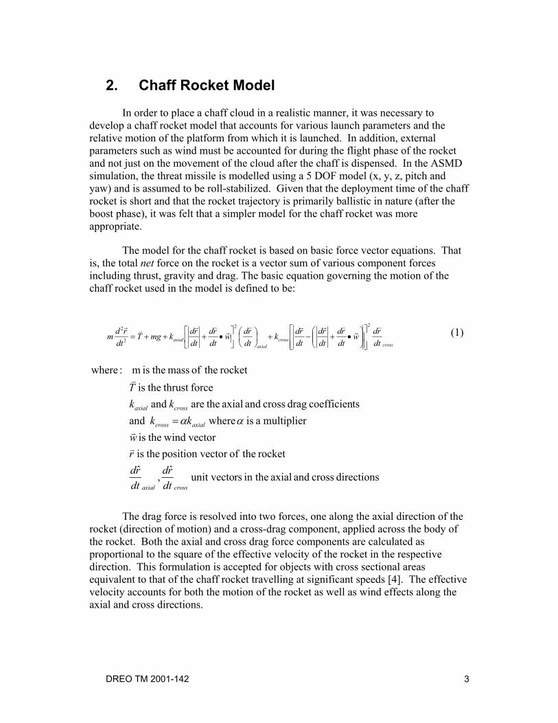
The model for the chaff rocket is based on basic force vector equations. That is, the total net force on the rocket is a vector sum of various component forces including thrust, gravity and drag. The basic equation governing the motion of the chaff rocket used in the model is defined to be:
crosscross
axialaxial dt
rdwdtrd
dtrd
dtrdk
dtrdw
dtrd
dtrdkmgT
dtrdm
)r
)rv)r
)rvr 22
2
2
•+−+
•+++= (1)
directions cross and axial in the rsunit vecto ˆ
,ˆ
rocket theofector position v theis vector wind theis
multiplier a is where and tscoefficien drag cross and axial theare and
force thrust theis rocket theof mass theis m :where
crossaxial
axialcross
crossaxial
dtrd
dtrd
rw
kkkk
T
v
v
v
αα=
The drag force is resolved into two forces, one along the axial direction of the rocket (direction of motion) and a cross-drag component, applied across the body of the rocket. Both the axial and cross drag force components are calculated as proportional to the square of the effective velocity of the rocket in the respective direction. This formulation is accepted for objects with cross sectional areas equivalent to that of the chaff rocket travelling at significant speeds [4]. The effective velocity accounts for both the motion of the rocket as well as wind effects along the axial and cross directions.
DREO TM 2001-142
4
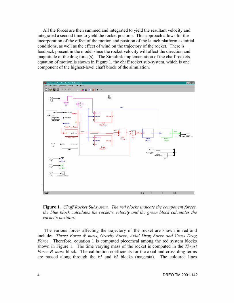
All the forces are then summed and integrated to yield the resultant velocity and integrated a second time to yield the rocket position. This approach allows for the incorporation of the effect of the motion and position of the launch platform as initial conditions, as well as the effect of wind on the trajectory of the rocket. There is feedback present in the model since the rocket velocity will affect the direction and magnitude of the drag force(s). The Simulink implementation of the chaff rockets equation of motion is shown in Figure 1, the chaff rocket sub-system, which is one component of the highest-level chaff block of the simulation.
Figure 1. Chaff Rocket Subsystem. The red blocks indicate the component forces, the blue block calculates the rocket’s velocity and the green block calculates the rocket’s position.
The various forces affecting the trajectory of the rocket are shown in red and include: Thrust Force & mass, Gravity Force, Axial Drag Force and Cross Drag Force. Therefore, equation 1 is computed piecemeal among the red system blocks shown in Figure 1. The time varying mass of the rocket is computed in the Thrust Force & mass block. The calibration coefficients for the axial and cross drag terms are passed along through the k1 and k2 blocks (magenta). The coloured lines
DREO TM 2001-142
5
connecting the different system blocks represent data flow between the blocks. The component forces are summed in the Sum Forces block and the net acceleration is computed in the Get Acc block by simply dividing the net force acting the rocket by the (time varying) mass of the rocket. The velocity of the rocket is computed in the Rocket Velocity block by simply integrating the acceleration over time and the rocket’s position is computed in a similar manner in the Rocket Position block. There are additional inputs to these two system blocks, which are given in the lower left hand corner of Figure 1. These inputs allow specification of the initial conditions for the velocity and position blocks from the main simulation so that the effect of the ships motion and position can be accounted for. Output from the Rocket Velocity block is also used to provide feedback into the force calculation blocks in order to compute velocity dependent effects.
Some additional features of our model include simulating the boost phase of the rocket as it is launched and variation in rocket mass as fuel is burned. This is done within the Thrust Force & mass block. After the boost phase of the rocket is complete, the model is essentially ballistic in nature and the trajectory is dependent on the effect of gravity, rocket velocity and drag. The model is considered to be an extension of a point model since a cross drag force is included.
DREO TM 2001-142
6
3. Implementation
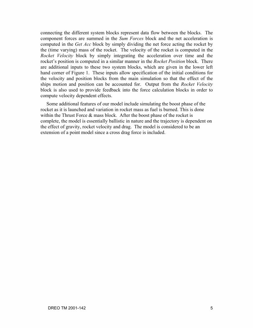
3.1 Thrust Force The sub-system that calculates the thrust force and time varying mass has been expanded in Figure 2. This block calculates the thrust force, T in equation 1. The inputs to this block include the initial thrust vector given by the launch bearing, pitch angle and rocket acceleration defined in the main simulation; time over which the thrust is applied and the rocket velocity (from feedback). The chaff rocket modeled is characterized by a constant thrust over a short time during the boost phase; hence the thrust is applied for a specific time, after which it is set to zero. The velocity of the rocket is then used to determine the direction of the applied thrust (after the initial thrust has been applied). The initial thrust vector is given by the launch bearing, ship heading, pitch and rocket acceleration. Selecting between the initial thrust vector and that given by the rocket velocity is accomplished through the Switch block with a time dependent threshold (Relational Operator1). The time over which thrust is applied is controlled through the Relational Operator block which compares the simulation time to the thrust time. The thrust force is calculated as the product of the rocket mass and acceleration due to thrust. Also calculated in this block is the variation of mass of the rocket over time. This variation in mass is stored in a time dependent look-up table, Look-up Table m(t), shown in orange. This is necessary since the rocket burns fuel throughout its trajectory. The model used based on a linear burn rate. A second output of the Thrust Force & mass block is the time varying mass that is used to calculate gravity effects.
DREO TM 2001-142
7
Figure 2. Expanded Thrust Block with look-up table for mass
3.2 Gravity
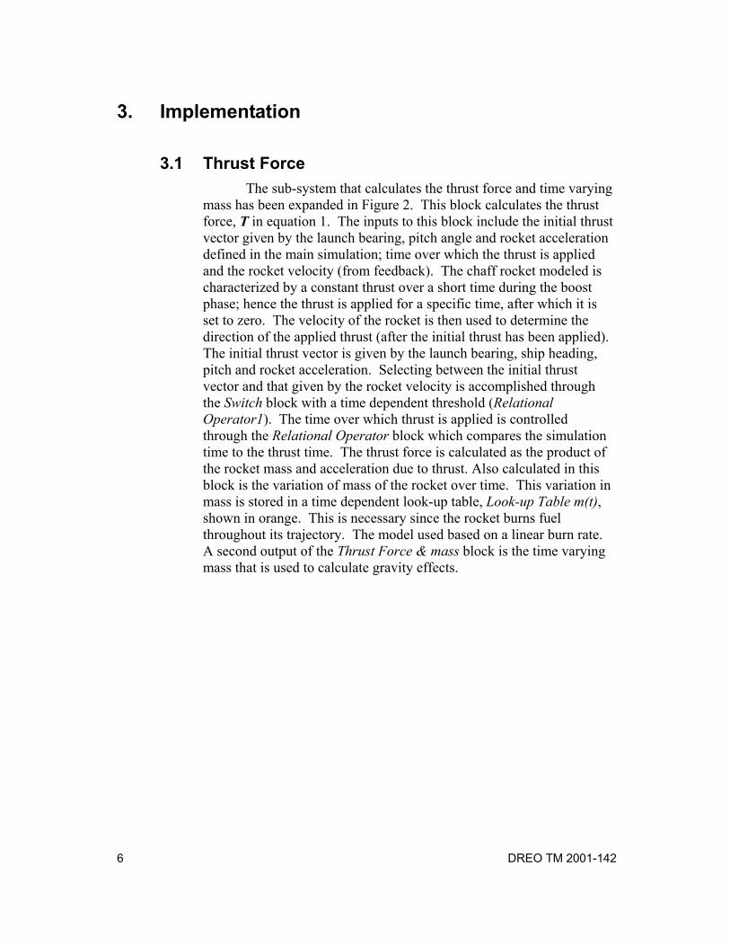
Of all the forces acting on the rocket, gravity is the simplest one to account for. The force of gravity on the rocket is given by the product of the acceleration due to gravity and the varying mass of the rocket. This sub-system is used to calculate mg in equation 1. The gravity force sub-system is shown in Figure 3. The main input to this block is the time varying mass, m(t) and the output is the force of gravity. The combination of the k-vector and Gain (9.81 m/s2) multiplied by the mass yields the desired force vector.
DREO TM 2001-142
8
Figure 3. Gravity sub-system
3.3 Axial Drag Force
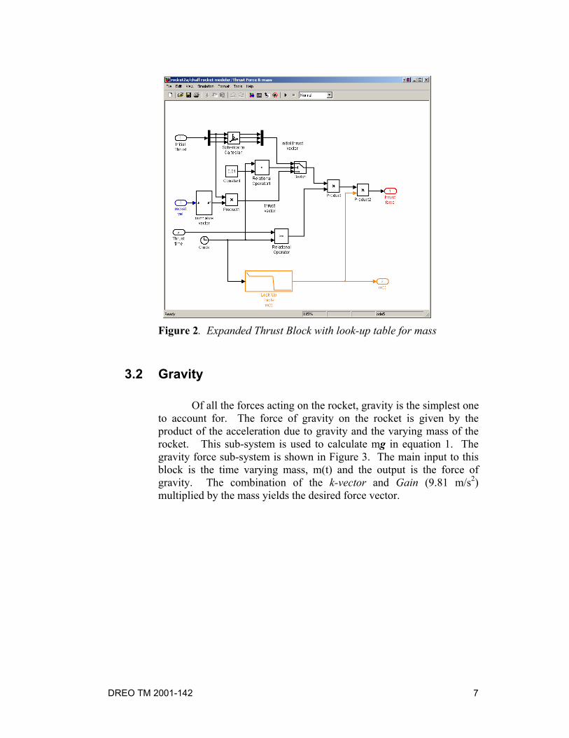
Axial drag on the rocket retards the ultimate height and range of the rocket and is a result of the movement of the rocket through the air and the effect of any wind. Figure 4 shows the expanded axial drag block. This force is modelled as the product of a drag coefficient and the square of the effective velocity along the rocket’s direction of travel (given by the normalized velocity vector). The effective velocity of the rocket through the air is determined by summing the rocket’s velocity with wind and then taking the dot product along the normalized velocity vector.
The inputs to this sub-system include the axial drag coefficient, k1, the rocket’s velocity and the wind. The rocket velocity and the wind vector are summed to yield the effective velocity vector and the magnitude of the effective velocity in the direction of travel of the rocket is given by the dot product of the summed force with the unit vector along the rocket’s direction of travel. The axial drag force is then computed by squaring the effective velocity and scaling it by the drag coefficient. The direction of the force is given by the normalized unit vector from the rocket’s direction of travel. The output of the block is the axial drag force as described in equation 1.
DREO TM 2001-142
9
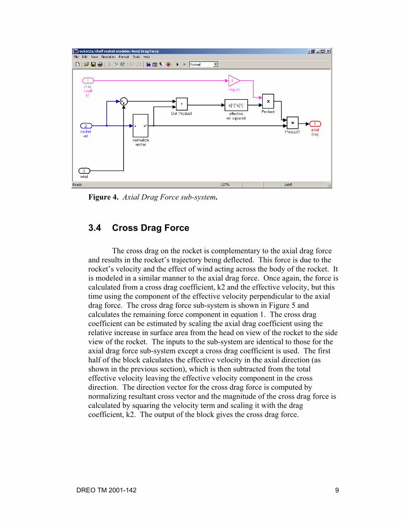
Figure 4. Axial Drag Force sub-system.
3.4 Cross Drag Force
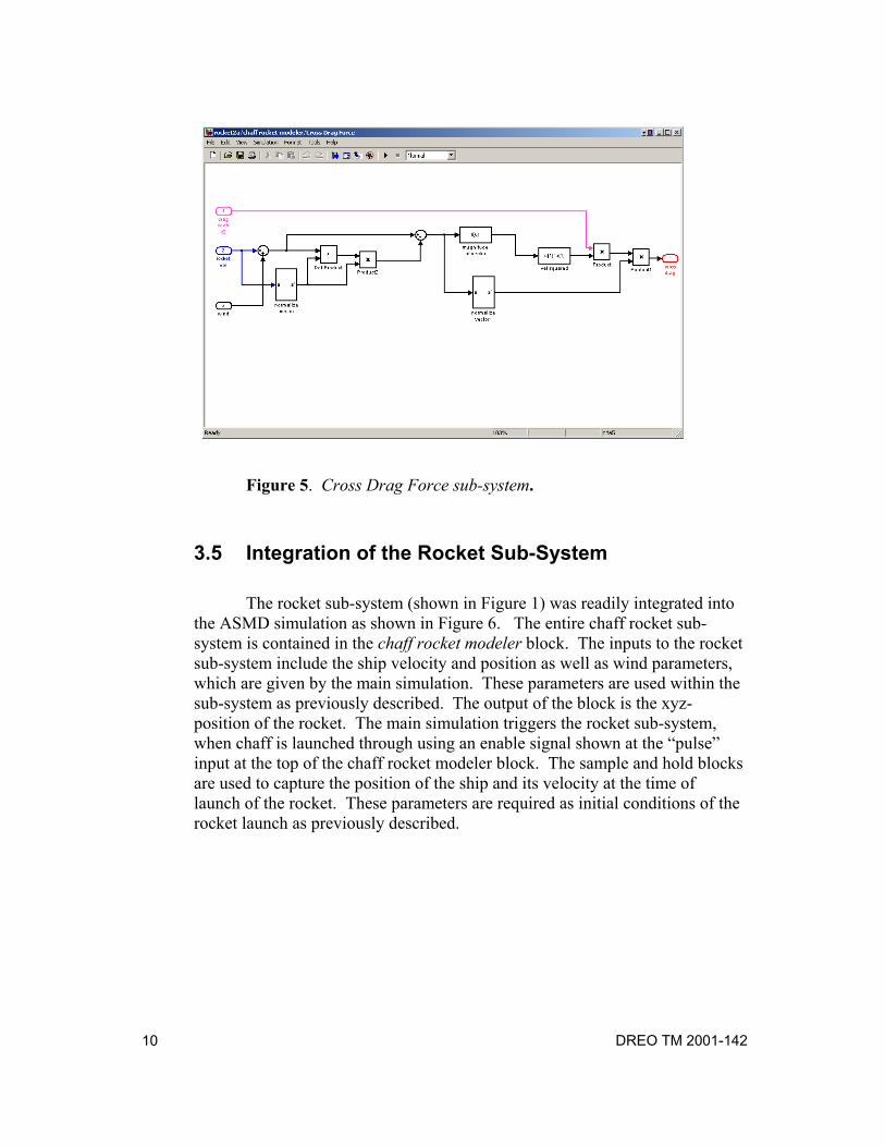
The cross drag on the rocket is complementary to the axial drag force and results in the rocket’s trajectory being deflected. This force is due to the rocket’s velocity and the effect of wind acting across the body of the rocket. It is modeled in a similar manner to the axial drag force. Once again, the force is calculated from a cross drag coefficient, k2 and the effective velocity, but this time using the component of the effective velocity perpendicular to the axial drag force. The cross drag force sub-system is shown in Figure 5 and calculates the remaining force component in equation 1. The cross drag coefficient can be estimated by scaling the axial drag coefficient using the relative increase in surface area from the head on view of the rocket to the side view of the rocket. The inputs to the sub-system are identical to those for the axial drag force sub-system except a cross drag coefficient is used. The first half of the block calculates the effective velocity in the axial direction (as shown in the previous section), which is then subtracted from the total effective velocity leaving the effective velocity component in the cross direction. The direction vector for the cross drag force is computed by normalizing resultant cross vector and the magnitude of the cross drag force is calculated by squaring the velocity term and scaling it with the drag coefficient, k2. The output of the block gives the cross drag force.
DREO TM 2001-142
10
Figure 5. Cross Drag Force sub-system.
3.5 Integration of the Rocket Sub-System
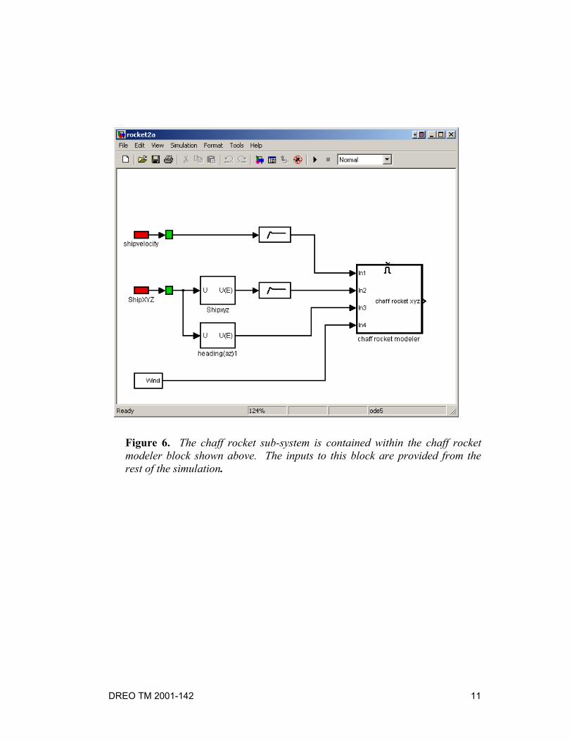
The rocket sub-system (shown in Figure 1) was readily integrated into the ASMD simulation as shown in Figure 6. The entire chaff rocket sub-system is contained in the chaff rocket modeler block. The inputs to the rocket sub-system include the ship velocity and position as well as wind parameters, which are given by the main simulation. These parameters are used within the sub-system as previously described. The output of the block is the xyz-position of the rocket. The main simulation triggers the rocket sub-system, when chaff is launched through using an enable signal shown at the “pulse” input at the top of the chaff rocket modeler block. The sample and hold blocks are used to capture the position of the ship and its velocity at the time of launch of the rocket. These parameters are required as initial conditions of the rocket launch as previously described.
DREO TM 2001-142
11
Figure 6. The chaff rocket sub-system is contained within the chaff rocket modeler block shown above. The inputs to this block are provided from the rest of the simulation.
DREO TM 2001-142
12
4. Results and Discussion
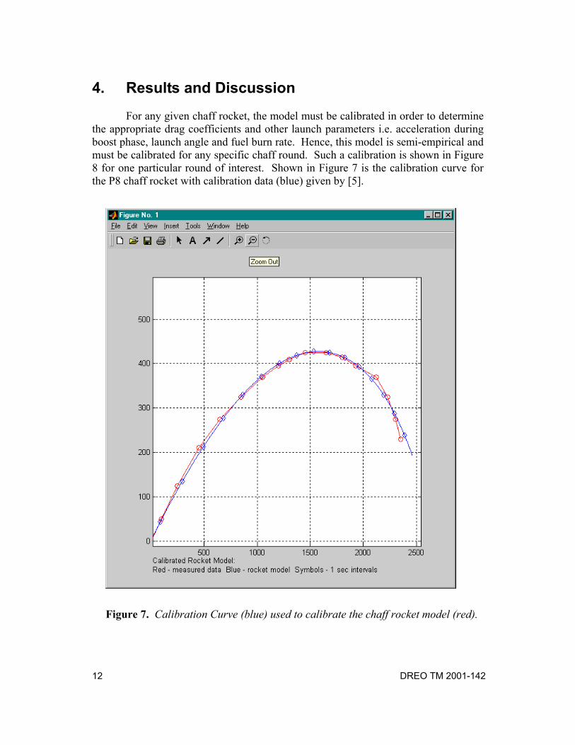
For any given chaff rocket, the model must be calibrated in order to determine the appropriate drag coefficients and other launch parameters i.e. acceleration during boost phase, launch angle and fuel burn rate. Hence, this model is semi-empirical and must be calibrated for any specific chaff round. Such a calibration is shown in Figure 8 for one particular round of interest. Shown in Figure 7 is the calibration curve for the P8 chaff rocket with calibration data (blue) given by [5].
Figure 7. Calibration Curve (blue) used to calibrate the chaff rocket model (red).

DREO TM 2001-142
13
The model and measured trajectory agree well. For this particular case, the axial drag coefficient was determined to be 0.0035 kg/m and the multiplier for the cross drag coefficient, α, was estimated to be 5.35. It was also necessary to determine values for the acceleration (and its duration) of the rocket during its boost phase and launch angle, as these were not available from other sources. For the rocket shown, the acceleration was calculated to be 200 m/sec2, for 1.2 sec at a launch angle of 39°.
The model was further tested by comparing the steady-state output of the chaff
rocket sub-system with steady-state equations derived from the original force vector formulation of the model, equation 1. Setting the original vector force equation to zero one can solve for the steady-state conditions, giving the following relationships:
θtan2
2
=BB
AA
vkvk
(2)
mgvkvk BBAA =+ θθ cossin 22 (3)
where: kA, kB are the axial and cross drag coefficients [kg/m]
vA, vB are the axial and cross velocity components [m/sec] θ is the angle the rocket is travelling wrt to the z-axis [degrees]
g is the force of gravity (9.81 m/s2) m is the final mass of the rocket [kg] By performing simulations for any combination of drag coefficients, the appropriate velocities and angles were extracted by looking at the final velocities vA and vB. These values were then used to compute equation 2 to yield θ and then compute equation 3. The purpose of this test was to determine if the Simulink implementation of the rocket model was consistent with the equation of motion defined in equation 1, at least in the steady state. Typically, the results were in agreement within 1%. For example, by choosing the following:
kA = 0.1 and kB = 0.5 with the final mass of the rocket, m = 15 kg The rocket simulation gives values of vA = 37.42 m/sec and vB = 9.515 m/sec Equation 2 yields, θ = 72.08 deg These values are consistent with equation 3. In practice however, this situation is never reached since chaff is typically
deployed within a few seconds of launch.
DREO TM 2001-142
14
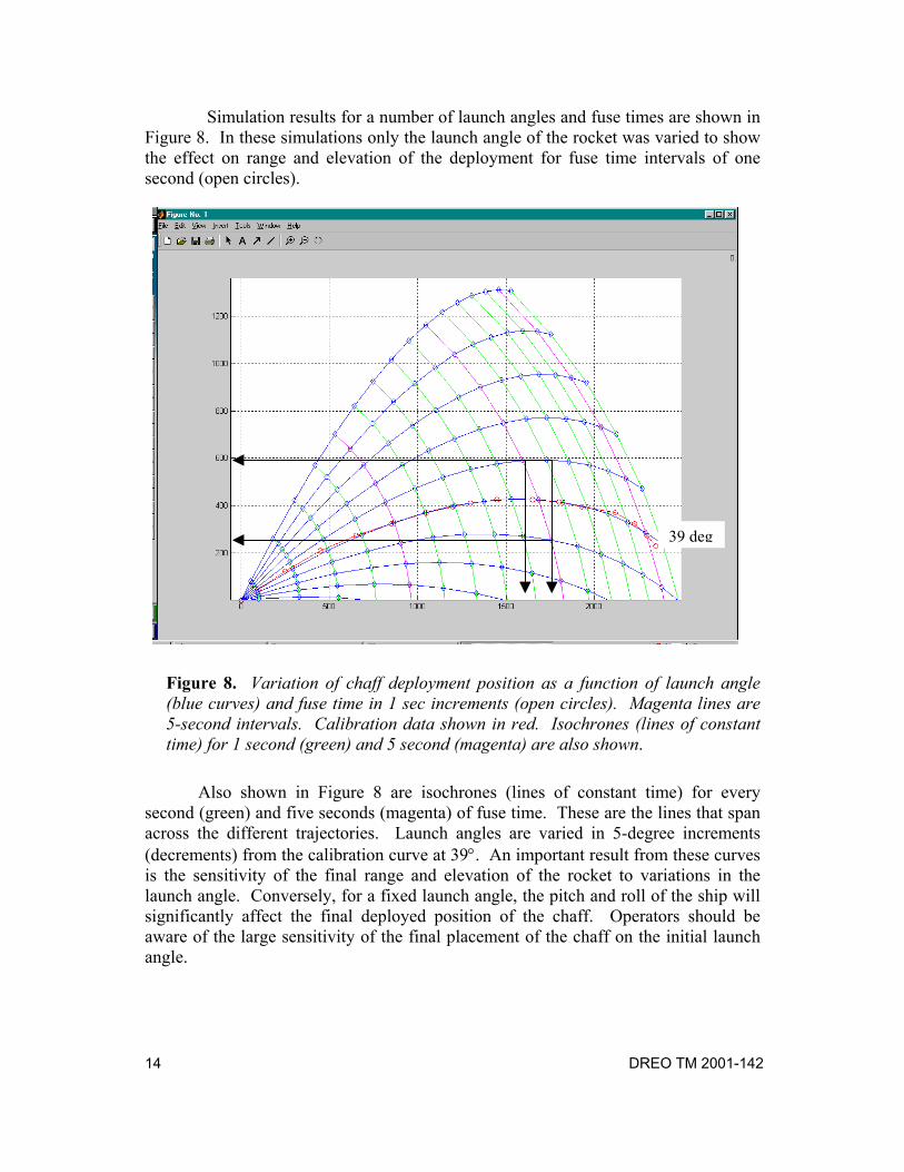
Simulation results for a number of launch angles and fuse times are shown in Figure 8. In these simulations only the launch angle of the rocket was varied to show the effect on range and elevation of the deployment for fuse time intervals of one second (open circles).
Figure 8. Variation of chaff deployment position as a function of launch angle (blue curves) and fuse time in 1 sec increments (open circles). Magenta lines are 5-second intervals. Calibration data shown in red. Isochrones (lines of constant time) for 1 second (green) and 5 second (magenta) are also shown.
Also shown in Figure 8 are isochrones (lines of constant time) for every
second (green) and five seconds (magenta) of fuse time. These are the lines that span across the different trajectories. Launch angles are varied in 5-degree increments (decrements) from the calibration curve at 39°. An important result from these curves is the sensitivity of the final range and elevation of the rocket to variations in the launch angle. Conversely, for a fixed launch angle, the pitch and roll of the ship will significantly affect the final deployed position of the chaff. Operators should be aware of the large sensitivity of the final placement of the chaff on the initial launch angle.
39 deg
DREO TM 2001-142
15
For example, consider the situation of a ship in relatively calm seas where a small pitch angle of ±5° is not uncommon. Given a nominal launch angle of 40° for the chaff rocket and a fuse time of 10 seconds, the range over which the chaff could be placed is 1600 m to 1800 m. The height of the chaff placement varies much more significantly, from 300 m to 600 m. Ideally, the chaff would be placed at a range of 1750 m and at a height of 400 m. This relatively large variation in the final placement should not be underestimated since it could mean the difference between successfully defeating the threat or not. This example further illustrates the need for a realistic rocket model for ASMD studies [6].
DREO TM 2001-142
16
5. Conclusion
For anti-ship missile defence, the accurate placement of chaff is critical for successfully defeating an active RF threat. The final placement of the chaff is dependent on the chaff rocket characteristics and external factors such as the motion of the launching platform and wind conditions.
In previous simulations, chaff was deployed according to a specified launch
time, bloom time and at a chosen position. This deployment scheme is not realistic since it does not incorporate the dynamics of the engagement.
In order to place a chaff cloud in a realistic manner in ASMD simulations, a
chaff rocket model was developed that accounts for various launch parameters, relative motion of the platform and wind conditions. The model for the chaff rocket is based a force vector equations approach modelled and implemented using Matlab/Simulink. Some additional features of our model include simulating the boost phase of the rocket and the variation in rocket mass as fuel is burned.
The model is semi-empirical and requires calibration with a chaff rocket of
interest. One such case was presented here, in which the model was calibrated using experimental rocket trajectory data, for the P8 chaff round. The agreement between the calibrated model and experimental data is excellent with a margin of error less than 1%.
The model has been integrated into the ASMD software and can now be used
in more realistic simulations for evaluation of chaff tactics. The model can also be used in a stand-alone fashion in order to evaluate the impact of various rocket and external parameters on the final placing of chaff. For example, it was determined that the rocket trajectory was particularly sensitive to the pitch angle used and this would be of particular interest in developing ASMD tactics since greater care would need to be exercised in determining the launch parameters to maximize ship survivability. In addition, the effect of various fuse times can also be studied. A limited number of fuse times would restrict deployment options and would therefore reduce effectiveness particularly for different modes of operation i.e. confusion, distraction and seduction. Finally, the effect of wind can also be studied and the effect of wind deflection on tactics should be considered. The chaff rocket model can be used to predicate the final placing of the chaff and future work would include developing a system which could use the model in the inverse sense i.e. given a target position for the chaff, the initial launch parameters could be determined. The system would most likely employ an iterative optimization technique e.g. EM method to determine the “initial” launch parameters if the model is used a predictor.
DREO TM 2001-142
17
References
[1] Defence Research and Development Maritime Client Group Service Level Agreement 2001-2003. [2] Manji, N (2001) Naval EW Engagement Modelling and Simulation for Anti-ship Missile Defence. Proceedings of the Advanced Technology Electronic Defence Systems and Situational Awareness Conference. Compact Disc. [3] Ozard JM, Tucker T, Vigder W, Whitmore S (2000) Dynamic Electronic Engagement Simulation: An Open and Extensible Approach with HWIL Applications. Military, Government and Aerospace Simulation, vol 32:3. Proceedings of the ASTC 2000. [4] Fowles, GR. Analytical Mechanics, 4th Ed. Holt, Rinehart and Winston, Orlando, Florida, 1986. [5] Stanier JD (1996) Characteristics of the P8 Chaff Round. DREO REPORT 1295. Defence Research Establishment Ottawa. [6] Ozard JM, Johnson J, Wong J (1999) Chaff and jamming effectiveness simulator for anti-ship cruise missile engagement: validation and application. DREO TM 1999-061. Defence Research Establishment Ottawa.
DREO TM 2001-142
18
List of symbols/abbreviations/acronyms/initialisms
ASMD Anti-Ship Missile Defence
CIWS Close In Weapon System
COTS Commercial Off The Shelf
DIR Defence Industrial Research
DND Department of National Defence
DOF Degrees of Freedom
ECM Electronic Countermeasures
ECCM Electronic Counter-Countermeasures
EW Electronic Warfare
RF Radio Frequency
SAM Surface to Air Missile
TTI Tactical Technologies Incorporated
UNCLASSIFIED SECURITY CLASSIFICATION OF FORM
(highest classification of Title, Abstract, Keywords)
DOCUMENT CONTROL DATA (Security classification of title, body of abstract and indexing annotation must be entered when the overall document is classified)
1. ORIGINATOR (the name and address of the organization preparing the document. Organizations for whom the document was prepared, e.g. Establishment sponsoring a contractor’s report, or tasking agency, are entered in section 8.)
Defence Research Establishment Ottawa Ottawa Ontario K1A 0Z4
2. SECURITY CLASSIFICATION (overall security classification of the document,
including special warning terms if applicable) UNCLASSIFIED
3. TITLE (the complete document title as indicated on the title page. Its classification should be indicated by the appropriate abbreviation (S,C or U) in parentheses after the title.)
The Development of a Chaff Rocket Model for Naval Anti-ship Missile Defence(U)
4. AUTHORS (Last name, first name, middle initial)
Manji, Nekmohamed S
5. DATE OF PUBLICATION (month and year of publication of document)
December 2001
6a. NO. OF PAGES (total containing information. Include Annexes, Appendices, etc.)
28
6b. NO. OF REFS (total cited in document)
6
7. DESCRIPTIVE NOTES (the category of the document, e.g. technical report, technical note or memorandum. If appropriate, enter the type of report, e.g. interim, progress, summary, annual or final. Give the inclusive dates when a specific reporting period is covered.)
Technical Memorandum
8. SPONSORING ACTIVITY (the name of the department project office or laboratory sponsoring the research and development. Include the address.)
Defence Research Establishment Ottawa
9a. PROJECT OR GRANT NO. (if appropriate, the applicable research and development project or grant number under which the document was written. Please specify whether project or grant)
N/A
9b. CONTRACT NO. (if appropriate, the applicable number under which the document was written)
N/A
10a. ORIGINATOR’S DOCUMENT NUMBER (the official document number by which the document is identified by the originating activity. This number must be unique to this document.)
DREO TM 2001-142
10b. OTHER DOCUMENT NOS. (Any other numbers which may be assigned this document either by the originator or by the sponsor)
N/A
11. DOCUMENT AVAILABILITY (any limitations on further dissemination of the document, other than those imposed by security classification) ( X ) Unlimited distribution ( ) Distribution limited to defence departments and defence contractors; further distribution only as approved ( ) Distribution limited to defence departments and Canadian defence contractors; further distribution only as approved ( ) Distribution limited to government departments and agencies; further distribution only as approved ( ) Distribution limited to defence departments; further distribution only as approved ( ) Other (please specify):
12. DOCUMENT ANNOUNCEMENT (any limitation to the bibliographic announcement of this document. This will normally correspond to
the Document Availability (11). However, where further distribution (beyond the audience specified in 11) is possible, a wider announcement audience may be selected.)
UNLIMITED
UNCLASSIFIED
SECURITY CLASSIFICATION OF FORM DDCCDD0033 22//0066//8877
UNCLASSIFIED SECURITY CLASSIFICATION OF FORM
13. ABSTRACT ( a brief and factual summary of the document. It may also appear elsewhere in the body of the document itself. It is highly desirable that the abstract of classified documents be unclassified. Each paragraph of the abstract shall begin with an indication of the security classification of the information in the paragraph (unless the document itself is unclassified) represented as (S), (C), or (U). It is not necessary to include here abstracts in both official languages unless the text is bilingual).
A simple, yet realistic chaff rocket model has been developed in MATLAB/Simulink in order simulate chaff deployment for anti-ship missile defence. The mathematical model is based on a force vector equations approach and simulates the various forces acting on the rocket including thrust, drag and gravity. Some additional features of the model include simulation of the boost phase of the rocket and variation in rocket mass as fuel is burned. External factors including wind, launch bearing, pitch angle and fuse time of the rocket have also been included. The model can be considered as an extension of a point model since a cross drag force is included.
14. KEYWORDS, DESCRIPTORS or IDENTIFIERS (technically meaningful terms or short phrases that characterize a document and could be helpful in cataloguing the document. They should be selected so that no security classification is required. Identifiers such as equipment model designation, trade name, military project code name, geographic location may also be included. If possible keywords should be selected from a published thesaurus. e.g. Thesaurus of Engineering and Scientific Terms (TEST) and that thesaurus-identified. If it is not possible to select indexing terms which are Unclassified, the classification of each should be indicated as with the title.)
Electronic Countermeasures (ECM) Chaff Anti-ship Missile Defence (ASMD) Electronic Warfare (EW) Naval Modelling and Simulation
UNCLASSIFIED
SECURITY CLASSIFICATION OF FORM