Embed Size (px)
Citation preview
Journal of Materials Processing Technology 169 (2005) 1–4
Technical note
The development of 3D models through rapid prototyping concepts
D.M.C. Santosa, A.E.M. Pertencea, H.B. Camposa, P.R. Cetlinb,∗a Department of Mechanical Engineering, UFMG, Cidade Universitaria, Pampulha, 31270-901, B. Horizonte, MG, Brazil
b Department of Metallurgical and Materials Engineering, UFMG, Rua Espirito Santo 35, 30160-030, B. Horizonte, MG, Brazil
Received 6 November 2003; received in revised form 6 January 2004; accepted 8 June 2004
Abstract
Three-dimensional models are being increasingly used as prototypes in various areas of manufacturing, research and education. They areespecially useful in the evaluation of elements typical of mechanical design, but are also important in architecture, medicine, arts, etc. Thesemodels can be developed using various methods, such as mass modeling, surface planification, and rapid prototyping (RP) with removal oraddition of material based on a CAD/CAM platform. This latter approach was employed in the present paper. Complex solids are formedthrough the association of elementary solids such as spheres, prisms, cylinders, torus, etc., and then rapid prototyping is applied involving aslicing process. A virtual model based on a CAD platform allows the determination of paths for each sliced level. These are translated inton©
K
1
odsssnom
aybt
oco
m-ring
ds,ro-ndghndms,edDedandr-.
nity
0d
umerical control codes, and fed to a milling process of a blank, allowing the manufacturing of a 3D model.2005 Elsevier B.V. All rights reserved.
eywords: 3D models; Elementary solids; Rapid prototyping
. Introduction
Mechanical parts represent an important fraction of vari-us products widely used in our society. Fierce competitionemands a permanent increase in productivity and faster re-ponse to changing technical and commercial demands onuch parts. This has led to widespread use of automatic de-ign procedures, based on either traditional mechanics or onumerical methods such as finite element analysis (FEA), inrder to evaluate stress and strain levels. Such analyses de-and an initial 3D modeling of the part under consideration.An increased interest in 3D models of mechanical parts is
lso observed. These serve as prototypes, allowing the anal-sis of the interference with other parts, of the kinematicehavior of the product and of the manufacturing processes
o be employed in the production of the part.The conceptualization and preparation of such models is
f special importance in the education and research in me-hanical engineering. It allows a far better 3D visualizationf parts, leading to enhanced geometric interpretation and
∗ Corresponding author.
spatial analysis of mechanical parts. This is of particular iportance in the areas of mechanical design and manufactuprocesses[1,2].
These models can be developed using various methosuch as mass modeling, surface planification, and rapid ptotyping (RP) with removal or addition of material based oa CAD/CAM platform. This latter approach was employein the present paper. Complex solids are formed throuthe Boolean association (involving addition, subtraction aintersection) of elementary solids such as spheres, priscylinders, torus, etc., and then rapid prototyping is appliinvolving a slicing process. A virtual model based on a CAplatform allows the determination of paths for each sliclevel. These are translated into numerical control codes,fed to a milling process of a blank, allowing the manufactuing of a 3D model.Figs. 1 and 2illustrate the above procedure
2. The 3DForm program
The “3DForm” is a computer program for the generatioof 3D models, originally developed at the Federal Univers
E-mail address: [email protected] (P.R. Cetlin). of Minas Gerais, in Brazil. It uses the association of elemen-
924-0136/$ – see front matter © 2005 Elsevier B.V. All rights reserved.oi:10.1016/j.jmatprotec.2004.06.035
2 D.M.C. Santos et al. / Journal of Materials Processing Technology 169 (2005) 1–4
Fig. 1. The association of elementary solids in order to obtain a 3D model.
tary solids in order to obtain complex shapes. The “3DForm”works as a “Client” program, controlling the generation of theelementary solids, and manages “Slave” programs such as aCAD platform offering a programming interface for externaluse of its commands[3–5].
The “3DForm” employed the Visual Basic® six languagein order to control an AutoCAD® 2000 platform. Its mainfeatures are the following:
• Control of the generation of elementary solids (spheres,prisms, cones, cylinders, etc.) in a CAD platform, at de-sired positions and with the required dimensions.
• Application of Boolean operations of addition, subtractionand intersection of the above-mentioned solids, allowingthe construction of 3D mechanical parts.
• Allows the permanent edition visualization and printing,from various observation viewpoints, of the 3D mechanicalparts under analysis.
• Slicing of the parts modeled in the CAD platform, at anydesired position and slicing interval, leading to RP proce-dures.
• Capturing, treating and storing of the geometric data gen-erated in the slicing process, for each cutting plane in themechanical part.
• Development of CNC code files for a pre-defined equip-ment, allowing the creation of an automatic sequence for
and
re-s sedo treea theo leted
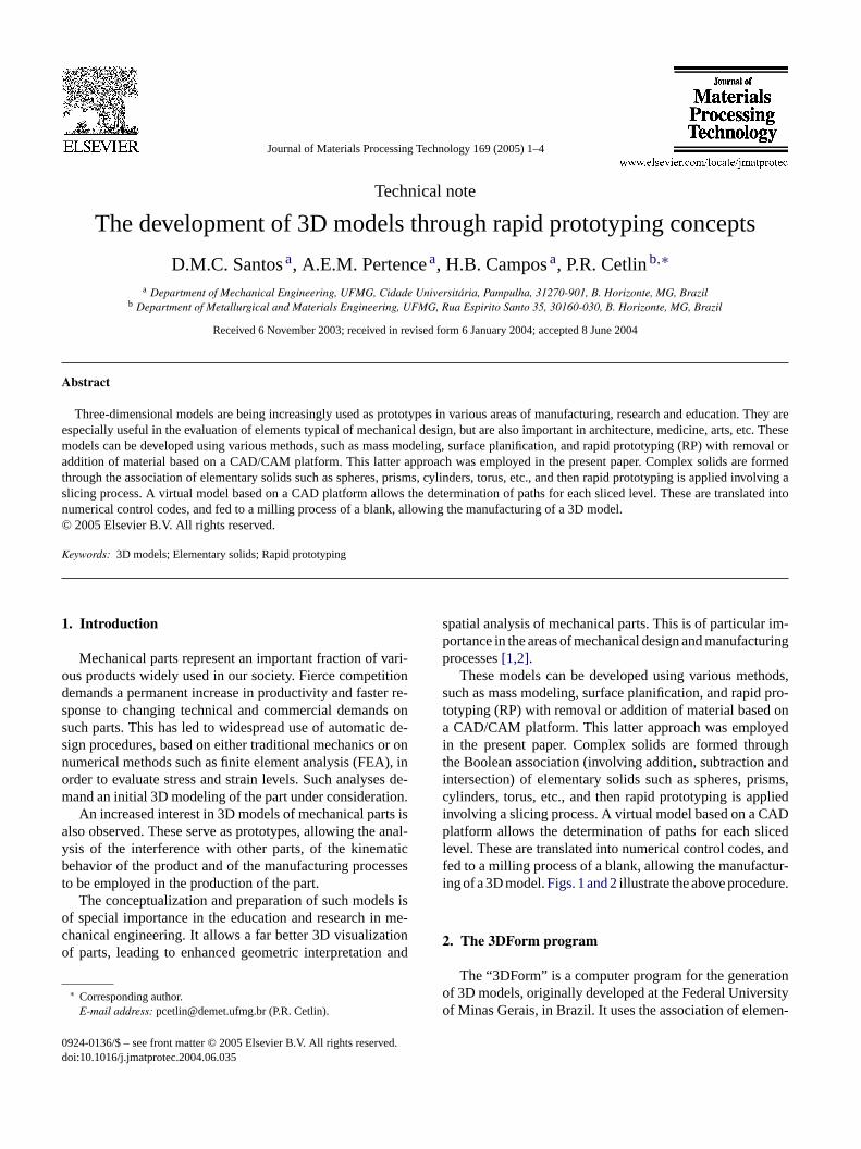
Fig. 3. Main screen of the 3DForm program.
or partially constructed part. The interface is user friendlyand the commands are easily accessible.
The main screen of the 3DForm program is shown inFig. 3, and can be divided into five areas with pre-definedfunctions:
• The region of the main commands is in the upper part ofthe screen. It contains the commands for object creation,for Boolean operations, for the generation of G codes, etc.
• The region in the upper left region of the screen displaysthe instantaneous creation sequence of the part, allowinga clear tracking of all the steps followed by the user.
• The region in the upper right region of the screen displaysthe visualization commands, involving the definition ofpreferential views and of the colors of the created solids.
• The region in the lower left of the screen allows the in-troduction of the data for the creation of the elementarysolids. This data is permanently saved and can be accessedat any moment.
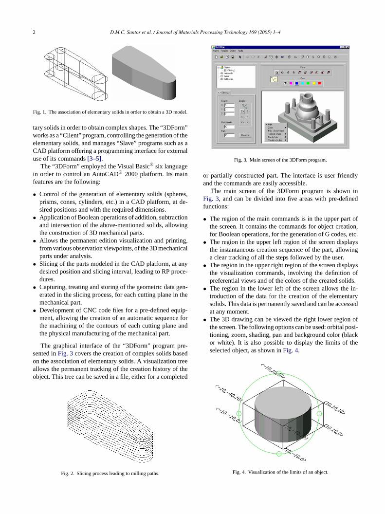
• The 3D drawing can be viewed the right lower region ofthe screen. The following options can be used: orbital posi-tioning, zoom, shading, pan and background color (blackor white). It is also possible to display the limits of theselected object, as shown inFig. 4.
the machining of the contours of each cutting planethe physical manufacturing of the mechanical part.
The graphical interface of the “3DForm” program pented inFig. 3covers the creation of complex solids ban the association of elementary solids. A visualizationllows the permanent tracking of the creation history ofbject. This tree can be saved in a file, either for a comp
Fig. 2. Slicing process leading to milling paths.
Fig. 4. Visualization of the limits of an object.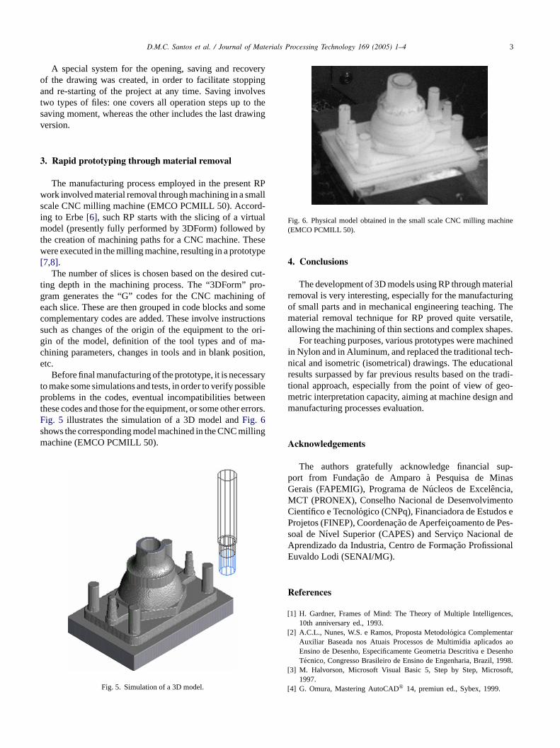
D.M.C. Santos et al. / Journal of Materials Processing Technology 169 (2005) 1–4 3
A special system for the opening, saving and recoveryof the drawing was created, in order to facilitate stoppingand re-starting of the project at any time. Saving involvestwo types of files: one covers all operation steps up to thesaving moment, whereas the other includes the last drawingversion.
3. Rapid prototyping through material removal
The manufacturing process employed in the present RPwork involved material removal through machining in a smallscale CNC milling machine (EMCO PCMILL 50). Accord-ing to Erbe[6], such RP starts with the slicing of a virtualmodel (presently fully performed by 3DForm) followed bythe creation of machining paths for a CNC machine. Thesewere executed in the milling machine, resulting in a prototype[7,8].
The number of slices is chosen based on the desired cut-ting depth in the machining process. The “3DForm” pro-gram generates the “G” codes for the CNC machining ofeach slice. These are then grouped in code blocks and somecomplementary codes are added. These involve instructionssuch as changes of the origin of the equipment to the ori-gin of the model, definition of the tool types and of ma-c ition,e
saryt siblep eent rrors.Fs llingm
Fig. 6. Physical model obtained in the small scale CNC milling machine(EMCO PCMILL 50).
4. Conclusions
The development of 3D models using RP through materialremoval is very interesting, especially for the manufacturingof small parts and in mechanical engineering teaching. Thematerial removal technique for RP proved quite versatile,allowing the machining of thin sections and complex shapes.
For teaching purposes, various prototypes were machinedin Nylon and in Aluminum, and replaced the traditional tech-nical and isometric (isometrical) drawings. The educationalresults surpassed by far previous results based on the tradi-tional approach, especially from the point of view of geo-metric interpretation capacity, aiming at machine design andmanufacturing processes evaluation.
Acknowledgements
The authors gratefully acknowledge financial sup-port from Fundac¸ao de Amparoa Pesquisa de MinasGerais (FAPEMIG), Programa de Nucleos de Excelencia,MCT (PRONEX), Conselho Nacional de DesenvolvimentoCientıfico e Tecnologico (CNPq), Financiadora de Estudos eProjetos (FINEP), Coordenac¸ao de Aperfeic¸oamento de Pes-soal de Nıvel Superior (CAPES) and Servic¸o Nacional deA lE
R
[ es,
[ rosenho1998.
[ oft,
[
hining parameters, changes in tools and in blank postc.
Before final manufacturing of the prototype, it is neceso make some simulations and tests, in order to verify posroblems in the codes, eventual incompatibilities betw
hese codes and those for the equipment, or some other eig. 5 illustrates the simulation of a 3D model andFig. 6hows the corresponding model machined in the CNC miachine (EMCO PCMILL 50).
Fig. 5. Simulation of a 3D model.
prendizado da Industria, Centro de Formac¸ao Profissionauvaldo Lodi (SENAI/MG).
eferences
1] H. Gardner, Frames of Mind: The Theory of Multiple Intelligenc10th anniversary ed., 1993.
2] A.C.L., Nunes, W.S. e Ramos, Proposta Metodologica ComplementaAuxiliar Baseada nos Atuais Processos de Multimıdia aplicados aEnsino de Desenho, Especificamente Geometria Descritiva e DeTecnico, Congresso Brasileiro de Ensino de Engenharia, Brazil,
3] M. Halvorson, Microsoft Visual Basic 5, Step by Step, Micros1997.
4] G. Omura, Mastering AutoCAD® 14, premiun ed., Sybex, 1999.

4 D.M.C. Santos et al. / Journal of Materials Processing Technology 169 (2005) 1–4
[5] D.J. Foley, Computer Graphics: Principles and Practice, Addison-Wesley, 1990.
[6] H.H. Erbe, E. e Sepulveda, La Tecnologia de Prototipos Rapidos ysus Aportes al Desarrollo de Productos, Congreso Iberoamericano deIngenierıa Mecanica, 1999.
[7] A.A. Ruiz, I.F. e Cruz, Sistema CAD/CAM Parametrico, CongresoIberoamericano de Ingenierıa Mecanica, 1999.
[8] P.Ag Maho, Numerical Control NC, IFAO Informations SystemGmbH, 1991.