Embed Size (px)
Citation preview
THE UNIVERSITY
OF ILLINOIS
LIBRARY
THE DETERMINATION OF DIELECTRIC CONSTANTS
BY A RESONANCE METHOD
EARLE HORACE WARNER
A. B. University of Denver, 1912
4
THESIS
Submitted in Partial Fulfillment of the Requirements for the
Degree of
MASTER OF ARTS
IN PHYSICS
IN
THE GRADUATE SCHOOL
OF THE
UNIVERSITY OF ILLINOIS Jh,
1914
Digitized by the Internet Archive
in 2013
http://archive.org/details/determinationofdOOwarn
UNIVERSITY OF ILLINOIS
THE GRADUATE SCHOOL
May 30 i9(j 4
1 HEREBY RECOMMEND THAT THE THESIS PREPARED UNDER MY SUPERVISION BY
SARLE HORACE WARNER
ENTITLED THE DETERMINATION OF DIELECTRIC CONSTANTS
BY A RESONANCE METHOD
BE ACCEPTED AS FULFILLING THIS PART OF THE REQUIREMENTS FOR THE
DEGREE OF MASTER OF ARTS
In Charge of Major Work
Head of Department
Recommendation concurred in:
Committee
on
Final Examination
284662
UKJC
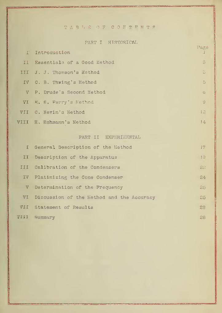
TABLE OF CONTENTS
PART I HISTORICALPage
1 Introduction L
II Essentials of a Good Method S
III J. J. Thomson's Method 5
IV C . B . Thwing's Method 5
V P. Drude's Second Method g
VI E. S. Ferry's Method 9
VII C. Nevin's Method 12
VIII H. Rohmann's Method 14
PART II EXPERIMENTAL
I General Description of the Method J
7
II Description of the Apparatus 1.9
III Calibration of the Condensers 22
IV Platinizing the Cone Condenser 24
V Determination of the Frequency 25
VI Discussion of the Method and the Accuracy 25
VII Statement of Results 23
VIII Summary 28
— —— —™— ——— —— —
PART I HISTORICAL
I INTRODUCTION
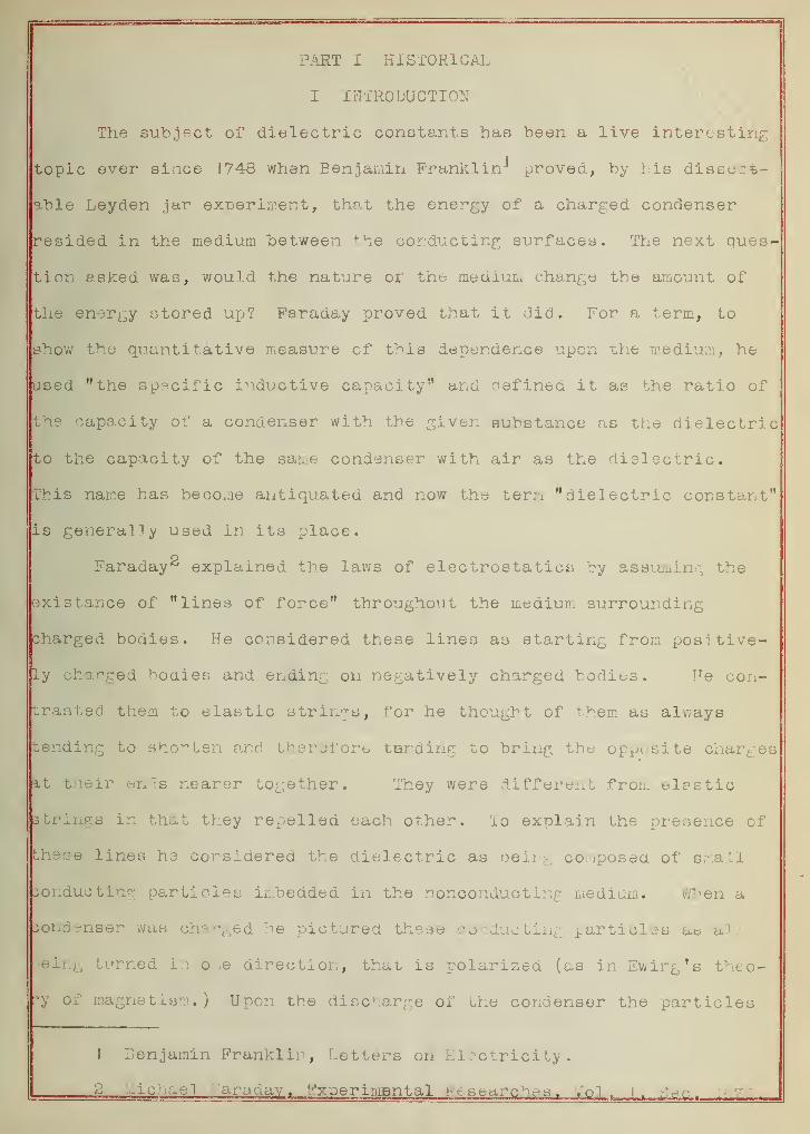
The subject of dielectric constants has been a live interesting
topic ever since 1748 when Benjamin Franklin-* proved, by bis dissect-
able L-eyden jar experiment, that the energy of a charged condenser
resided in the medium between the conducting surfaces. The next ques-
tion asked was, would the nature of the medium change the amount of
the energy stored up? Faraday proved that it did. For a term, to
show the quantitative measure of this dependence upon the medium, he
used "the specific inductive capacity" and defined it as the ratio of
the capacity of a condenser with the given substance as the dielectric
to the capacity of the same condenser with air as the dielectric.
This name has become antiquated and now the term "dielectric constant"
is generally used in its place.
Faraday^ explained the laws of electrostatics by assuming the
existance of "lines of force" throughout the medium surrounding
charged bodies. He considered these lines as starting from positive-
ly charged bodies and ending on negatively charged bodies. He con-
trasted them to elastic strings, for he thought of them as always
tending to shorten and therefore tending to bring the opposite charges
at their ends nearer together. They were different from elastic
3trings in that they repelled each other. To explain the presence of
these lines he considered the dielectric as being composed of small
conducting particles imbedded in the nonconducting medium. When a
condenser was charged be pictured these conducting particles as all
ieing turned in one direction, that is polarized (as in Swing's theo-
ry of magnetism. ) Upon the discharge of the condenser the particles
J Benjamin Franklin, Letters on Electricity.
| ....icbael ^radav_ t_ V'x^erimBntal h e searches. ,ol. i
f,-'eo. 1 .
2
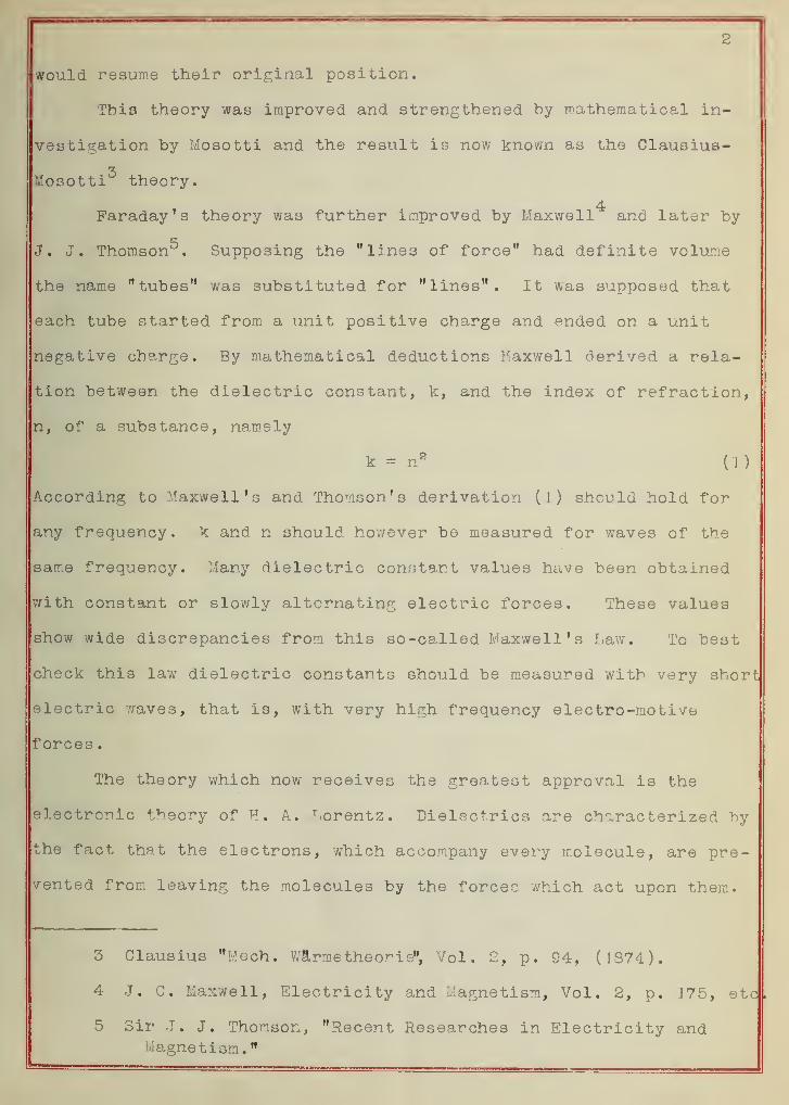
would resume their original position.
This theory was improved and strengthened by mathematical in-
vestigation by Mosotti and the result is now known as the Clausius-
Mosotti theory.
4Faraday's theory was further improved by Maxwell and later by
J. J. Thomson5 . Supposing the "lines of force" had definite volume
the name "tubes" was substituted for "lines". It was supposed that
each tube started from a unit positive charge and ended on a unit
negative charge. By mathematical deductions Maxwell derived a rela-
tion between the dielectric constant, k, and the index of refraction,
n, of a substance, namely
k = n 2(1)
According to Maxwell's and Thomson's derivation (I) should hold for
any frequency. k and n should however be measured for waves of the
same frequency. Many dielectric constant values have been obtained
with constant or slowly alternating electric forces. These values
show wide discrepancies from this so-called Maxwell's Law. To best
check this law dielectric constants should be measured with very short
electric waves, that is, with very high frequency electro-motive
forces
.
The theory which now receives the greatest approval is the
electronic theory of H. A.. T.orentz. Dielectrics are characterized by
the fact that the electrons, which accompany every molecule, are pre-
vented from leaving the molecules by the forces which act upon them.
3 Glausius "Mech. W&rme theorie", Vol. 2, p. 94, (1 374).
4 J. C. Maxwell, Electricity and Magnetism, Vol. 2, p. J 75, etc
5 Sir J. J. Thomson, "Recent Researches in Electricity andMagnetism.
"
3
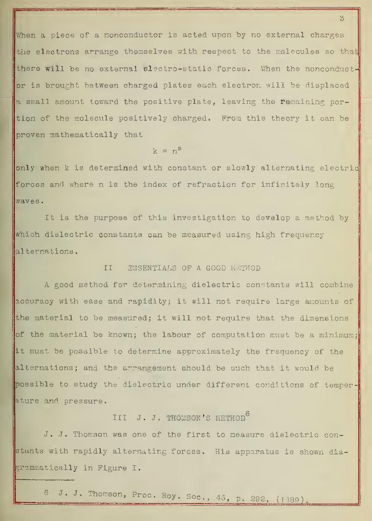
When a piece of a nonconductor is acted upon by no external charges
the electrons arrange themselves with respect to the molecules so that
there will be no external ©lectro-static forces. When the nonconduct-
or is brought between charged plates each electron will be displaced
a small amount toward the positive plate, leaving the remaining por-
tion of the molecule positively charged. Prom this theory it can be
proven mathematically that
k = n 2
only when k is determined with constant or slowly alternating electric
forces and where n is the index of refraction for infinitely long
waves
.
It is the purpose of this investigation to develop a method by
which dielectric constants can be measured using high frequency
alternations
.
II ESSENTIALS OF A GOOD METHOD
A good method for determining dielectric constants will combine
accuracy with ease and rapidity; it will not require large amounts of
the material to be measured; it will not require that the dimensions
of the material be known; the labour of computation must be a minimum;
it must be possible to determine approximately the frequency of the
alternations; and the arrangement should be such that it would be
possible to study the dielectric under different conditions of temper-
ature and pressure.
Ill J.J. THOMSON'S METHOD6
J. J. Thomson was one of the first to measure dielectric con-
stants with rapidly alternating forces. His apparatus is shown dia-
graamiatioally in Figure I.
6 J. J. Thomson, Proc, Roy . S0Cj) 48> p- S9g( ,, Jp ,_
4
b
Pig. I
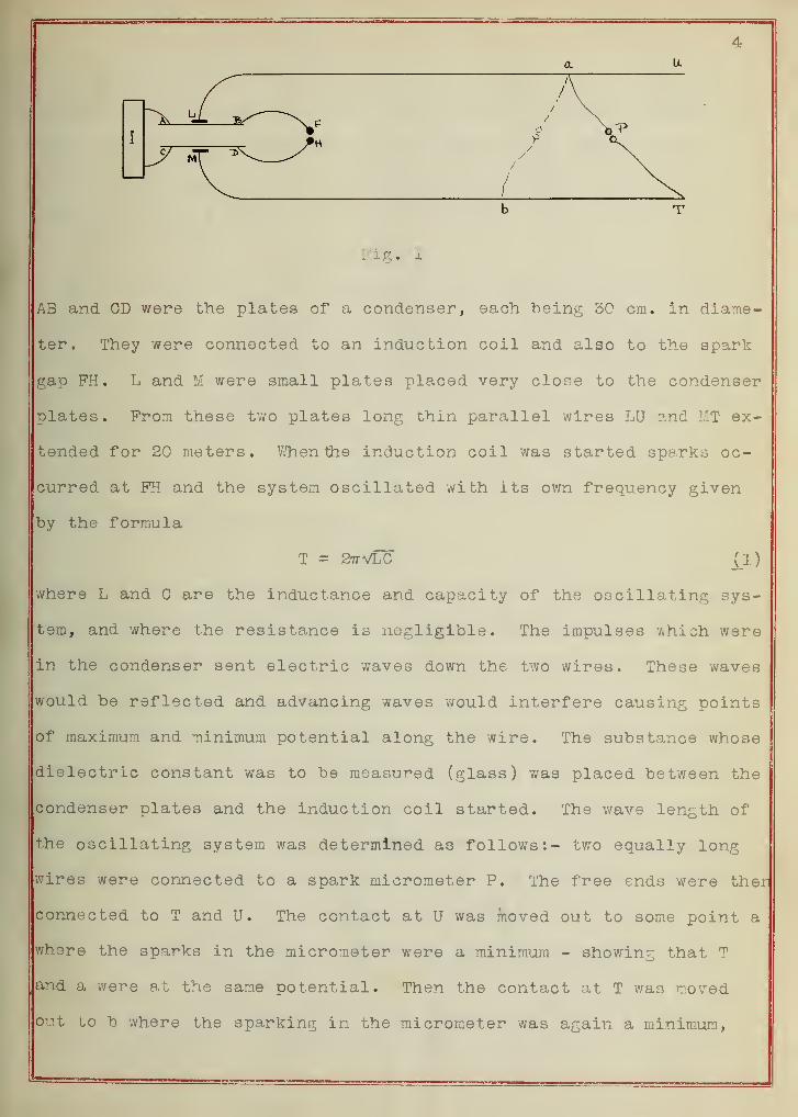
AB and CD were the plates of a condenser, each "being 30 cm. in diame-
ter. They were connected to an induction coil and also to the spark
gap FH. L and M were small plates placed very close to the condenser
plates. From these two plates long thin parallel wires LU and MT ex-
tended for 20 meters. When the induction coil was started sparks oc-
curred at FH and the system oscillated with its own frequency given
by the formula
T = 27TVLG O )
where L and C are the inductance and capacity of the oscillating sys-
tem, and where the resistance is negligible. The impulses which were
in the condenser sent electric waves down the two wires. These waves
would be reflected and advancing waves would interfere causing points
of maximum and minimum potential along the wire. The substance whose
dielectric constant was to be measured (glass) was placed between the
condenser plates and the induction coil started. The wave length of
the oscillating system was determined as follows:- two equally long
wires were connected to a spark micrometer P. The free ends were ther
connected to T and U. The contact at U was moved out to some point a
where the sparks in the micrometer were a minimum - showing that T
and a were at the same potential. Then the contact at T was moved
out to b where the sparking in the micrometer was again a minimum,
5
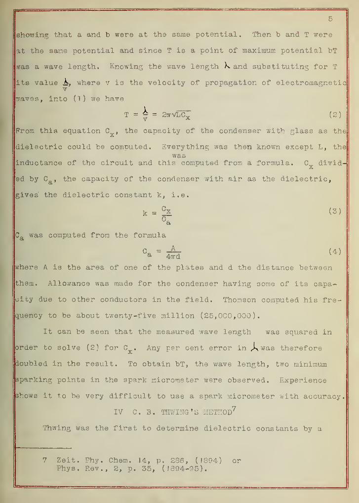
showing that a and b were at the same potential. Then b and T were
at the same potential and since T is a point of maximum potential bT
was a wave length. Knowing the wave length K. and substituting for T
its value K, where v is the velocity of propagation of electromagneticv
7/aves, into ('I) we have
= k -T = — = 2ttvLCy (2)v X N '
From this equation , the capacity of the condenser with glass as the
dielectric could be computed. Everything was then known except L, thewas
inductance of the circuit and this computed from a formula. C divid-
ed by C , the capacity of the condenser with air as the dielectric,
gives the dielectric constant k, i.e.
k = !k (3)
Ca was computed from the formula
where A is the area of one of the plates and d the distance between
them. Allowance was made for the condenser having some of its capa-
city due to other conductors in the field. Thomson computed his fre-
quency to be about twenty-five million (25,000,000).
It can be seen that the measured wave length was squared in
order to solve (2) for C . Any per cent error in jywas therefore
doubled in the result. To obtain bT, the wave length, two minimum
sparking points in the spark micrometer were observed. Experience
shows it to be very difficult to use a spark micrometer with accuracy.
IV C. 3. SEWING'S METHOD7
Thwing was the first to determine dielectric constants by a
7 Zeit. Phy. Chem. 14, p. 286, (1894) orPhys. Rev., 2, p. 35, (1394-95).
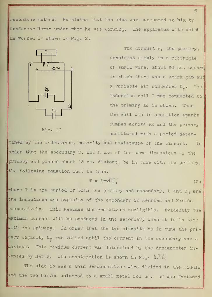
resonance method. He states that the idea was suggested to him by
Professor Hertz under whom he was working. The apparatus with which
he worked is shown in Pig. 2.
The circuit P, the primary,
consisted simply in a rectangle
of small wire, about 60 cm. square
in which there was a spark gap anc
-• •-
F H
+
r"-i
LftJ
Pic;. II
a variable air condenser C . TheP
induction coil I was connected to
the primary as is shown. V/hen
the coil was in operation sparks
jumped across FH and the primary
oscillated with a period deter-
mined by the inductance, capacity and resistance of the circuit. In
order that the secondary S, which was of the same dimensions as the
primary and placed about 1.5 cm. distant, be in tune with the primary,
the following equation must be true.
T = 27TVLC, (5)
where T is the period of both the primary and secondary, L and C a are
the inductance and capacity of the secondary in Henries and Farads
respectively. This assumes the resistance negligible. Evidently the
maximum current will be produced in the secondary when it is in tune
with the primary. In order that the two circuits be in tune the pri-
mary capacity Gp
was varied until the current in the secondary was a
maximum. This maximum current was determined by the dynamometer in-
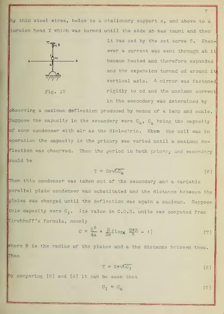
vented by Hertz. Its construction is shown in Fig. ^.TC
The side ab was a thin German-silver wire divided in the middle
and the two halves soldered to a small metal rod cd. cd was fastened
7
by thin steel wires, below to a stationary support e, and above to a
torsion head T which was turned until the side ab was taunt and then
it was set by the set screw S. When-
ever a current was sent through ab it
became heated and therefore expanded
and the expansion turned cd around it
vertical axis. A mirror was fastened
rigidly to cd and the maximum current
in the secondary was determined by
observing a maximum deflection produced by means of a lamp and scale.
Suppose the capacity in the secondary were Ca ,Ca being the capacity
of some condenser with air as the dielectric. When the coil was in
operation the capacity in the primary was varied until a maximum de-
flection was observed. Then the period in both primary and secondary
would be
T = 27rVLCa (6)
Then this condenser was taken out of the secondary anri a variable
parallel plate condenser was substituted and the distance between the
plates -was changed until the deflection was again a maximum. Suppose
this capacity were Cj . Its value in C.G.S. units was computed from
irchhoff's formula, namely
where R ia the radius of the plates and a the distance between them.
Then
T = SttVLCj (8)
By comparing (6) and (S) it can be seen that
In a similar way the capacity of the condenser with the unknown sub-
stance as the dielectric was found to he some value, say Og. Then by
definition of the dielectric constant, k would be
C2k = t jo
It is shown that when a spark jumps between two metal balls the
resulting oscillatory current is by no means constant. Thwing says
the alternate heating and cooling of the wire produces small oscil-
lations in the mirror, which while blurring the image to such an ex-
tent as to exclude the use of a reading telescope, are not sufficient
to prevent accurate readings with a lamp and scale." If his dyna-
mometer had been more sensitive this would not have been the case,
so for refined measurements a modification is necessary.
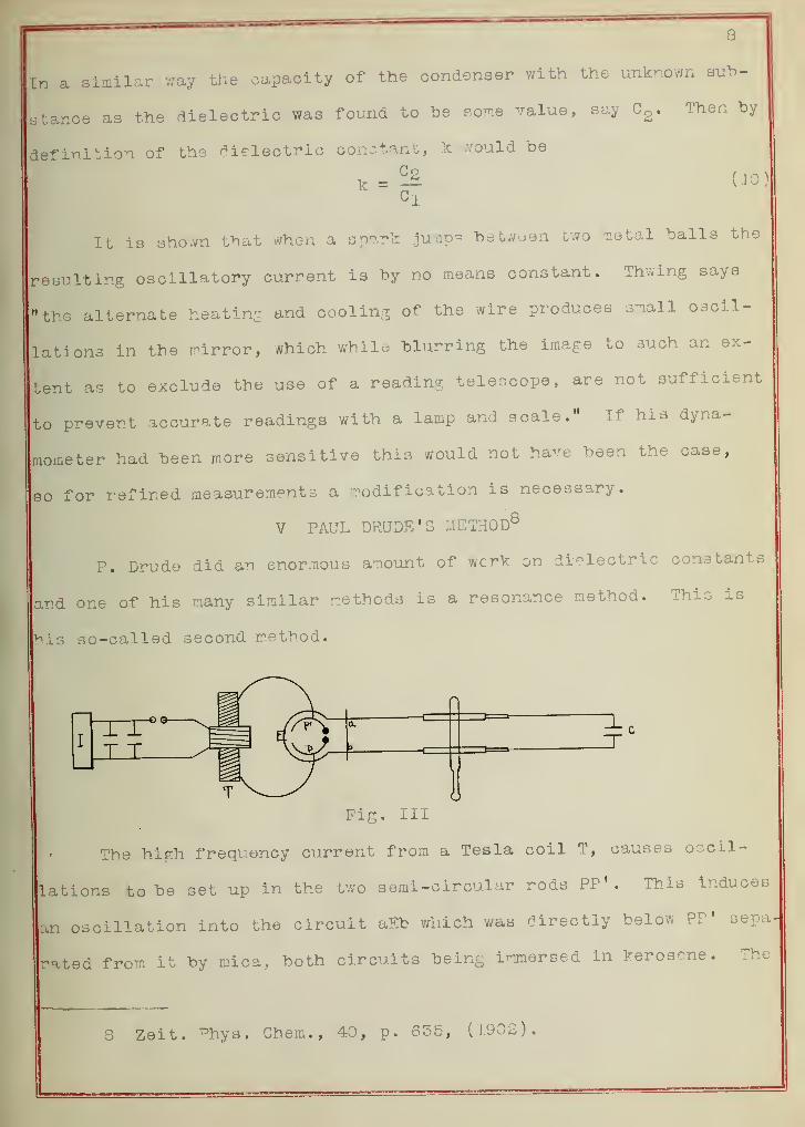
V PAUL DRUDE'S METHOD8
P. Drude did an enormous amount of wcrk on dielectric constants
and one of his many similar methods is a resonance method. This is
bis so-called second method.
Fig. Ill
The high frequency current from a Tesla coil T, causes oscil-
lations to be set up in the two semi-circular rods PP'. This induces
an oscillation into the circuit aEb which was directly below PP 1 sepa
rated from it by mica, both circuits being immersed in kerosene. The
S Zeit. ^hys. Chem., 40, p. 635, (1902).
9
resonating circuit is acb and it is tuned with the primary by decreas-
ing or increasing its inductance by pushing in or pulling cut the
telescoping tubes. The point of resonance was determined by the maxi*
mam glow of a G-iesler tube pieced between c and ab at a point of maxi-
mum potential. The capacity to be studied was c.
Tris method is similar to Thwing's with the exception +hat tun*
ing is accomplished by varying the inductance instead of the capacity.
In general the distance ac is not long and therefore the difficultyit
of obtaining accurately brings a considerable per cent error into the
result. Drude concluded that under the working conditions the error
might be from 2 to ofo.
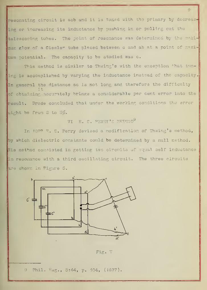
VI E. S. "PERRY'S METHOD9
In \Q97 E , S. Ferry devised a modification of Thwing's method,
by which dielectric cons bants could be determined by a null method.
His method consisted in getting two circuits of equal self inductance
in resonance with a third oscillating circuit. The three circuits
are shown in Figure 5.
Fig. V
9 Phil. 7^a.g., 5:44, p. 104, (1.897).
10
The oscillating circuit was mh and the two resonating systems were
pa'b and ga"d. When all three were in resonance the capacity C', Whid
I
was a variable parallel plate condenser, in ph must equal the capacity
C" , which was the capacity under consideration with air as the dielec-
tric, in gd because the period and inductance of the two circuits were
the same. Thus C" could be determined by computing C. Then when the
dielectric to be measured was in C w, changing its capacity to C^, and
C' had been changed to C-[ in order that the three circuits be in
resonance again, it could be said that C| (which was computed) was
equal to C" . Then by definition
K = 21 (13
)
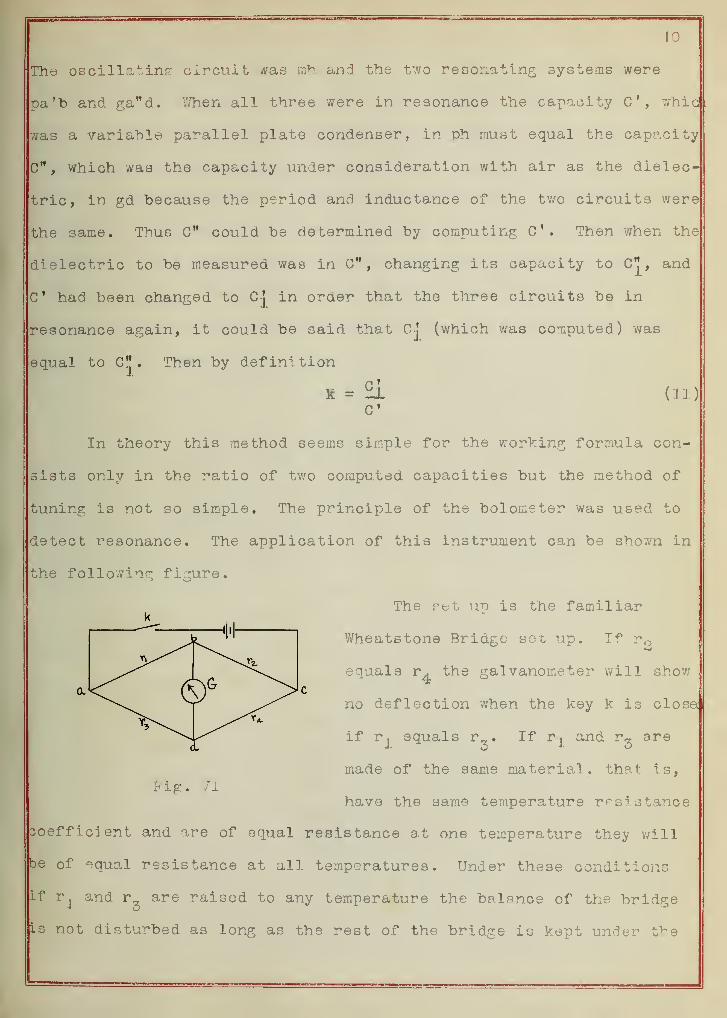
CIn theory this method seems simple for the working formula con-
sists only in the ratio of two computed capacities but the method of
tuning is not so simple. The principle of th9 bolometer was used to
detect resonance. The application of this instrument can be shown in
the following figure.
The set u"o is the familiark
Wheatstone Bridge sot up. If rQ
equals r. the galvanometer will shov;
no deflection when the key k is close
if rj equals r_. If rj and r^ are
made of the same material, that is,
have the same temperature resistance
Doefficient and are of equal resistance at one temperature they willj
be of equal resistance at all temperatures. Under these conditions
If rj and are raised to any temperature the balance of the bridgej
is not disturbed as long as the rest of the bridge is kept under the;
] J
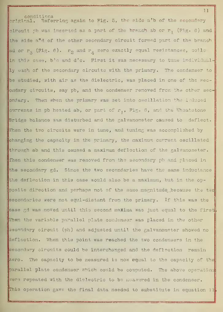
conditionsoriginal. Referring again to Pig. 5, the side a*b of the secondary
circuit pb was inserted as a part of the branch ab or p., (Fig. 6) and
the side a w d of the other secondary circuit formed part of the branch
ad or r„ (Fig. 6). r and t were exactly equal resistances, coils
in this case, b'c and d'c. First it was necessary to tune individual-
ly each of the secondary circuits with the primary. The condenser to
be studied, with air as the dielectric, was placed in one of the sec-
ondary circuits, say pb, and the condenser removed from the other sec-
ondary. Then when the primary was set into oscillation the induced
currents in pb heated ab, or part of r^, Fig. 6, and the Wheatstone
Bridge balance was disturbed and the galvanometer caused to deflect,
when the t'.vo circuits were in tune, and tuning was accomplished by
changing the capacity in the primary, the maximum current oscillated
through ab and this caused a maximum deflection of the galvanometer.
Then this condenser was removed from the secondary pb and placed in
the secondary gd. Since the two secondaries have the same inductance
the deflection in this case would also be a maximum, but in the op-
posite direction and perhaps not of the same magnitude., because the two
secondaries were not equi-distant from the primary. If this was the
case gd was moved until this second maxima was just equal to the first,
Then the variable parallel plate condenser was placed in the other
secondary circuit (ph) and adjusted until the galvanometer showed no
deflection. When this point was reached the two condensers in the
secondary circuits could be interchanged and the deflection remain
zero. The capacity to be measured is now equal to the capacity of the
parallel plate condenser which could be computed. The above operation
were repeated with the dielectric to be measured in the condenser.
jThis operation gave the final data needed to substitute In equation 11
,
J.2
It can be seen that the manipulation in this method, is not so
simple. Great care har also to be taken to protect the bolometer fron
temperature changes. Quoting from Ferry "all parts of the bolometer
must be carefully screened from heating effects. Air draughts and
similar sudden changes can be guarded against by thick coverings of
cotton wool." While this method is a null method the zero deflec-
tion is produced by the effects of the two maxima counterbalancing
each other, and each of the maxima had to be determined, in other wordji
the errors in determining each remain in the result.
Ferry computed the frequency of his oscillations to be about
33,000,000 per second.
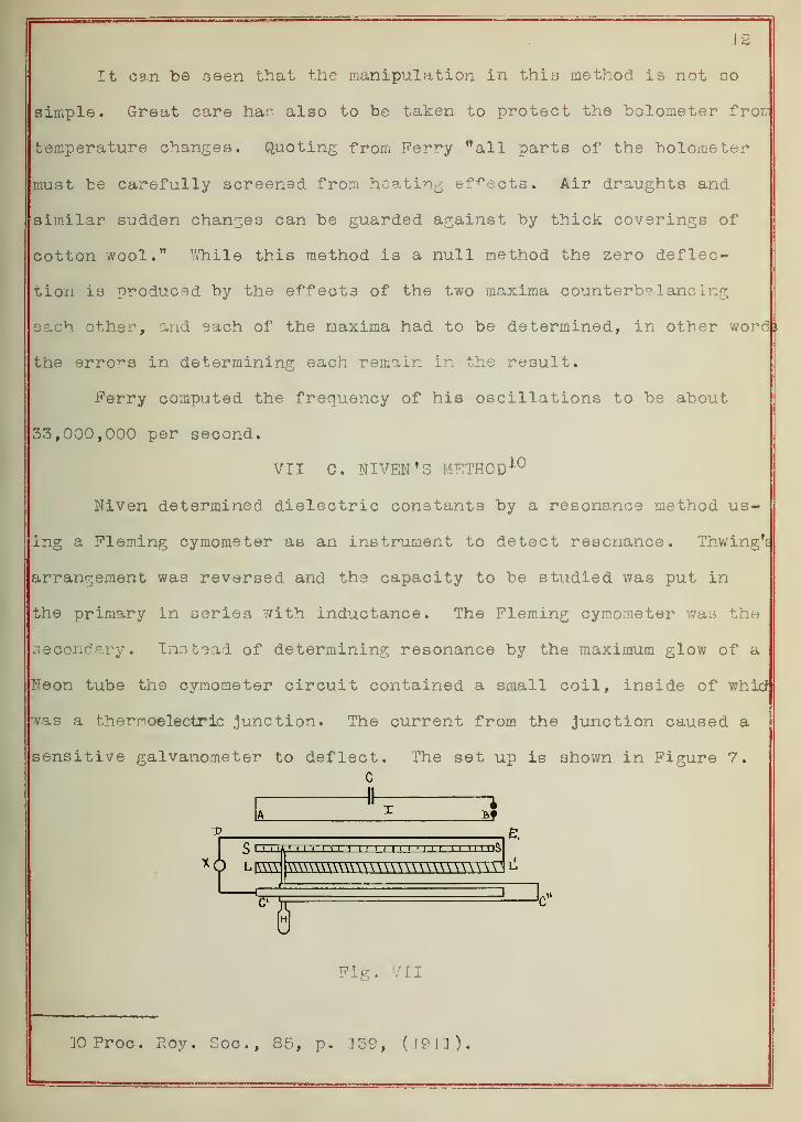
VII C. NIVEN*S METHOD10
Niven determined dielectric constants by a resonance method us-
ing a Fleming cymometer as an instrument to detect resonance. Thwing's
arrangement was reversed and the capacity to be studied was put in
the primary in series with inductance. The Fleming cymometer was the
secondary. Instead of determining resonance by the maximum glow of a
Neon tube the cymometer circuit contained a small coil, inside of whid
vas a thernoelectric junction. The current from the junction caused a
sensitive galvanometer to deflect. The set up is shown in Figure 7.
C
1i < 1 1 1
1
1 i 1 1 i i 1 1 1 u 1 1 1 1 1 1 1 1 is
WWWWWWWWWWWWWWWTH ^
Fig. 711
JOProc. Roy. Soc, 85, p. 1M, (!9I'J).
I o
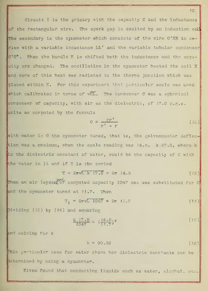
Circuit I is the primary with the capacity C and the inductance
of the rectangular wire. The spark gap is excited by an induction coil
The secondary is the cynometer which consists of the wire C'XE in se-
ries with a variable inductance LL' and the variable tubular condenser
C'C". When the handle H is shifted both the inductance and the capa-
city are changed. The oscillation in the cymometer heated the coil X
and some of this heat was radiated to the thermo junction which was
placed within X. For this experiment that particular scale was used
which calibrated in terms of VOL. The condenser C was a spherical
condenser of capacity, with air as the dielectric, of J7.8 c.g.s.
units as computed by the formula
C =t
rr '
(12)r' - r
with water in C the cymometer tuned, that is, the galvanometer deflec-
tion was a maximum, when the scale reading was I4..R. k 17.8, where k
is the dielectric constant of water, would be the capacity of C with
the water in it and if T is the period
T = 2ttVL k 17.8 = 2tt 14.5 (15)
Then an air leydedfof computed capacity 11047 cm. was substituted for C
and the cymometer tuned at 11.7. Then
Tj a 2ttVL 1047 = 2tt 11.7 (14)
Dividing (15) by (14) and squaring
k J7.8 , J4.5 . g (15)J047 "
K 11.7 )
jknd solving for k
k = 90.36 (16)
This particular case for water shows how dielectric constants can be
ietermined by using a cymometer.
Niven found that conducting liquids such as water, alcohol, etc.
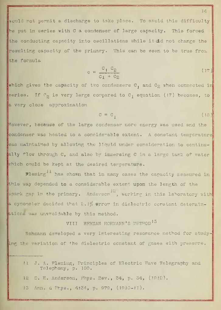
14
would not permit a discharge to take place. To avoid this difficulty
he put in series with C a condenser of large capacity. This forced
the conducting capacity into oscillations while it did not change the
resulting capacity of the primary. This can be seen to be true from
the formula
c =C
'
C2 (17)
Ci + C 2
which gives the capacity of two condensers C, and Cg when connected in
series. If Cn is very large compared to Cj equation (17) becomes, to
a very close approximation
C = Cj (18)
However, because of the large condenser more energy was used and the
condenser was heated to a considerable extent. A constant temperature
was maintained by allowing the liquid under consideration to continu-
ally flow through C, and also by immersing C in a large tank of water
Which could be kept at the desired temperature.
Fleming"^ has shown that in many cases the capacity measured in
this way depended to a considerable extent upon the length of the
<_ 12spark gap m the primary. Anderson , working in this laboratory with
a cymometer decided that 2. \<fo wrror in dielectric constant determin-
ations was unavoidable by this method.
VTTT HERMAN ROHMANN'S METHOD 13
Rohmann developed a very interesting resonance method for study-
ing the variation of +he dielectric constant of gases with pressure.
VI. J. A. Fleming, Principles of Electric Wave Telegraphy andTelephony, p. J 80.
IS S. H. Anderson, Phys . Rev., 34, p. 34, (19 12).
.13 Ann. dPhys., 4:34, p. 979, (J9J0-J1).
15
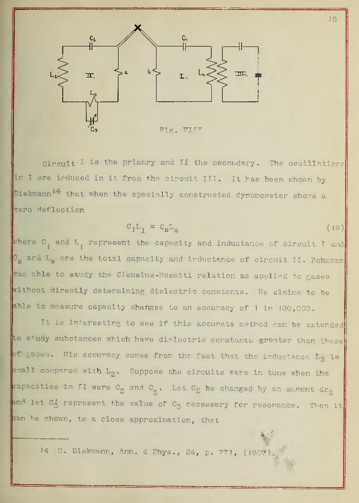
Circuit 1 is tne primary, and II the secondary. The oscillations
in I are induced in it from the circuit III. It has been shown by
Diekmann 14 that when the specially constructed dynamometer sfcows a
zero Reflection
°IL1 = °8Ls ' (19)
where and L represent the capacity and inductance of circuit I and
CQ
and LB are the total capacity and inductance of circuit II. F.ohmann
was able to study the CQ ausius-Mosotti relation as applied to cases
without directly determining dielectric constants. He claims to be
able to measure capacity changes to an accuracy of I in 100,000.
It is interesting to see if this accurate method can be extended
to s+udy substances which have dielectric constants greater than those
of ^ases. His accuracy comes from the fact that the inductance Lg is
3r.aH compared with Lg. Suppose the circuits were in tune when the
capacities in II were C and C . Let C2 be changed by an amount den
fad let C^ represent the value of C3 necessary for resonance. Tnen it
can be shown, to a close approximation, that
14 ::. Diekmann, Ann. d Phys., 24, p. 77!, (1907).
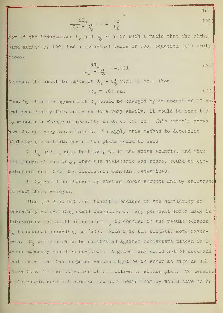
16s
dC2 L 3 (20)
C 3- Lg
Now if the inductances L2 and L3
were in such a ratio that the right
hand member of (20) had a numerical value of .00! equation (20) would
become
= -.001 ^ J'
C 3 " G3
Suppose the absolute value of - 65* ware 10 cm., then
dC« = .0 1 cm. (22)
Thus by this arrangement if C3
could be changed by an amount of JO cm.
and practically this could be done very easily, it would be possible
to measure a change of capacity in Cg of .O'J cm. This example shows
how the accuracy was obtained. To apply this method to determine
dielectric constants one of two plans could be used.
] L and L_ must be known, as in the above example, and then
the change of capacity, when the dielectric was added, could be com-
puted and from this the dielectric constant determined.
2. Co could be changed by various known amounts and C3 calibrate*
,o read these changes.
Plan (1) does not seem feasible because of the difficulty of
accurately determining small inductances. Any per cent error made in
determining the small inductance L„ is doubled in the result because
• is squared according to (20). Plan 2 is but slightly more favor-
able. C, would have to be calibrated against condensers placed in C2
whose capacity could be computed. A guard ring could not be used and
that means that the computed values might be in error as high as if,*
There is a further objection which applies to either plan. To measure
a. dielectric constant even as low as 2 means that would have to be
17
changed an enormous amount in order to offset the doubling of Cg when
the dielectric was placed between the plates. This is a cs.se where
the method of obtaining accuracy leads one to a design of apparatus
which is impossible to obtain practically.
So while this method is a very accurate one to study gases,
whose dielectric constants are low, it seems to be impractical for the
study of substances which have higher dielectric constants.
The spark gap in circuit III was such as to produce a quenched
spark. This has the great advantage of giving a constant uniform os-
cillation. It seems that this improvement could be applied with prof-
it to any of the previously described methods.
PART II EXPERIMENTAL
I GENERAL DESCRIPTION OF THE METHOD
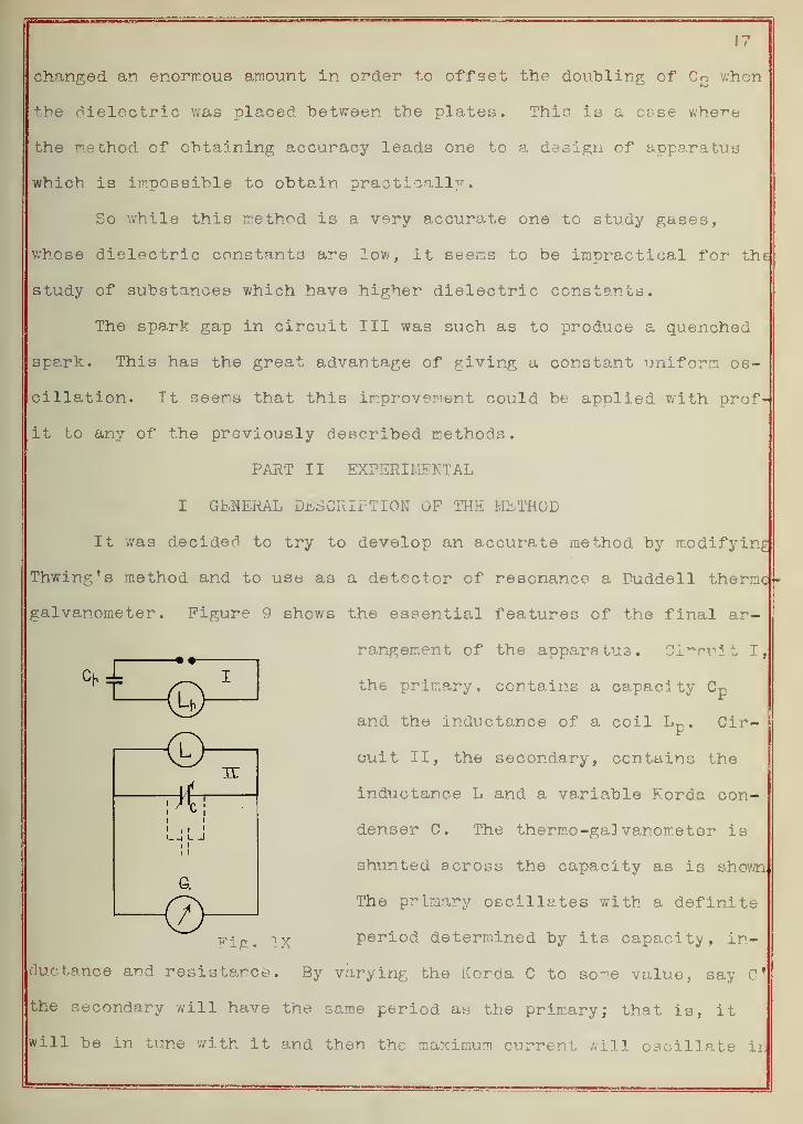
It was decided to try to develop an accurate method by modifying
Thwing's method and to use as a detector of resonance a Duddell theme
galvanometer. Figure 9 shows the essential features of the final ar-
rangement of the apparatus. Circuit I,
the primary, contains a capacity Cp
-• •-
<5>c—
'
ii
3T
i 1
1
I—| L J
and the inductance of a coil Lp. Cir-
cuit II, the secondary, contains the
inductance L and a variable Korda con-
denser C. The thermo-galvanometer is
shunted across the capacity as is shown
The primary oscillates with a definite
Fig, IX period determined by its capacity, in-
ductance and resistance. By varying the Korda C to some value, say 0*
the secondary will have the same period as the primary; that is, it
will be in tune with it and then the maximum current irill oscillate in
G..
IS
the secondary, and the thermo-galvanome ter will give a maximum deflec-
tion. Then
T = 2TVLCfr (23)
where T is the period of both the primary and secondary and L and 0*
the inductance and capacity of the secondary. Then the condenser un-
der consideration, a conical condenser with air as the dielectric,
was placed in parallel with the Korda as is shown by the dotted lines.
When placed in parallel its capacity is added to the Korda, therefore
to produce resonance the Korda had to be reduced to some value, say 0"
Then since the period is the same as before
T = 27rvL(C n +Ca ) (24)
where G& is the capacity of the cone with air as the dielectric. Then
the liquid to be studied was poured into th^ cone and the Korda tuned
at, say Cm . Then
T = 27rVL(C" + Cx ) (25)
where Cx is the capacity of the cone with the liquid being studied as
the dielectric. By comparing (23) and (24)
C" + Ca = G ' (2C N
Therefore
a = C - C M(gy)
3y comparing (23) and (25)
C"» + Cx = C»Therefore
Cx = 0' -
Then by definition of the dielectric constant k
v = = C - g£ (30)Ca C - C"
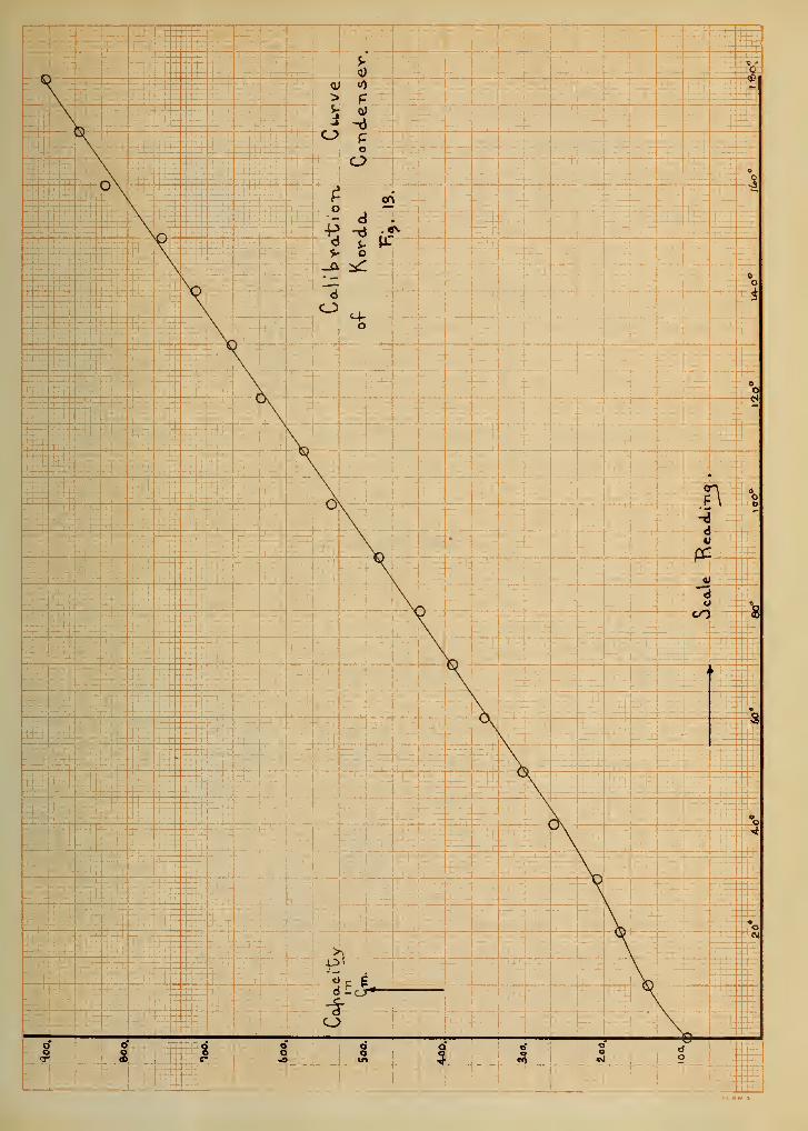
A calibration curve was plotted for the variable Korda C which gave
its capacity in cm. for any reading of the scale. So the C's in the
right hand member of the equation were obtained very easily. It was
(28)
(29)
J9
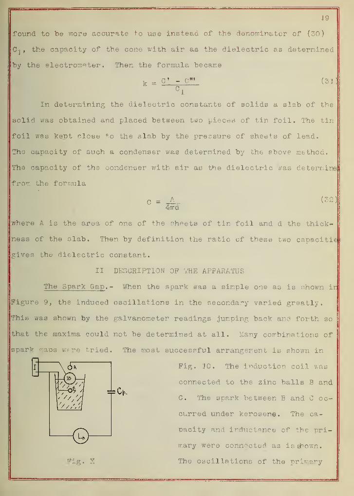
found to be more accurate to use instead of the denominator of (30)
C-j , the capacity of the cone with air as the dielectric as determined
by the electrometer*. Then the formula became
o Nf(33)
In determining the dielectric constants of solids a slab of the
solid was obtained and placed between two pieces of tin foil. The tin
foil was kept close to the slab by the pressure of sheets of lead.
The capacity of such a condenser was determined by the above method.
The capacity of the condenser with air as the dielectric was determine
from the formula
c = -A..47Td
(32)
where A is the area of one of the sheets of tin foil and d the thick-
ness of the slab. Then by definition the ratio of these two capacities
gives the dielectric constant.
II DESCRIPTION OF THE APPARATUS
The Spark Gap .- When the spark was a simple one as is shown Ik
Figure 9, the induced oscillations in the secondary varied greatly.
This was shown by the galvanometer readings jumping back and forth so
that the maxima could not be determined at all. Many combinations of
sparkj
v.aps were tried. The most successful arrangement is shown in
Fig. JO. The induction coil was
T7i
connected to the zinc balls B and
C. The spark between B and C oc-
curred under kerosene. The ca-
pacity and inductance of the pri-
mary were connected as is shown.
The oscillations of the primary
F
20
took place from A to B to C. The energy in the primary was so small
that the discharge was in the form of a very faint glow between A and
B. With this arrangement the induced currents in the secondary were
nearly constant and therefore the galvanometer deflections were nearly
constant
.
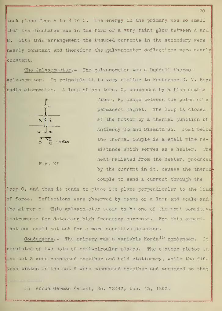
The Galvanometer .- The galvanometer was a Duddell thermo-
gal vanometer . In principle it is very similar to Professor C. V. Boys
radio micrometer. A loop of one turn, C, suspended by a fine quartz
fiber, P, hangs between the poles of a
permanent magnet. The loop is closed
at the bottom by a thermal junction of
Antimony Sb and Bismuth Bi. Just below
the thermal couple is a small wire re-
sistance which serves as a heater. The
heat radiated from the heater, produced
by the current in it, causes the thermo-
couple to send a current through the
loop C, and then it tends to place its plane perpendicular to the line
of force. Deflections were observed by means of a lamp and scale and
the mirror m. This galvanometer seems to be one of the most sensitive
instruments for detecting high frequency currents. For this experi-
ment ore could not ask for a more sensitive detector.
Condensers . - The primary was a variable Korda-*^ condenser. It
consisted of two sets of semi-circular plates. The sixteen plates in
the set S were connected together and held stationary, while the fif-
teen plates in the set M were connected together and arranged so that
Pig. XT
<xte r.
15 Korda German latent, No. 7£447, Dec. J 3, IS93.
21
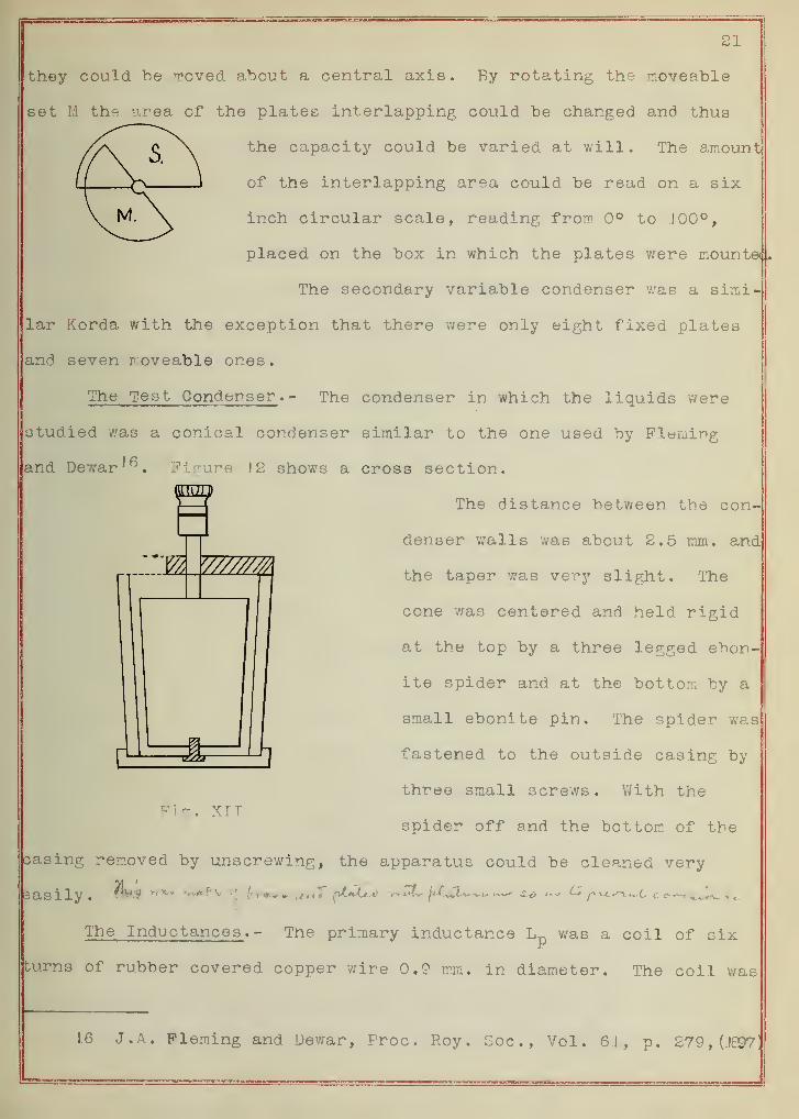
they could be moved about a central axis. By rotating the moveable
set M the y,rea of the plates interlapping could be changed and thus
^ \ the capacity could be varied at will. The amount
of the interlapping area could be read on a six
inch circular scale, reading from 0° to 100°,
placed on the box in which the plates were mounted.
The secondary variable condenser was a simi-
lar Korda with the exception that there were only eight fixed plates
and seven r oveable ones.
The Test Condenser .- The condenser in which the liquids were
studied was a conical condenser similar to the one used by Fleming
and Dewar'^. Figure 12 shows a cross section.
GGIZD
C
fiK. XTT
The distance between tne con-
denser walls was about 2.5 mm. and
the taper was very slight. The
cone was centered and held rigid
at the top by a three legged ebon-
ite spider and at the bottom by a
small ebonite pin. The spider was
fastened to the outside casing by
three small screws. With the
spider off and the bottom of the
casing removed by unscrewing, the apparatus could be cleaned very
asily . >v**-$ v fi lrr***s ^LtU^ v>v*k jdL&L^t* <—* •£-«•> *** ^ajl^^jL cci^^vy^
The Inductances .- The primary inductance Lp
was a coil of six
burns of rubber covered copper wire 0.9 mm. in diameter. The coil was
16 J. A. Fleming and Dewar, Proc. Roy. Soc, Vol. 61, p. 279,0897
r 22
wound on a wood disc 14.5 cm. in diameter.
The secondary inductance Ls was simply one turn of the same a ize
wire wound on a similar disc.
The Induction Coil .- The coil used was a Max Kchl 30 cm. induc-
tion coil. Such a large coil was not needed however, for only a small
amount of energy was consumed.
The variable Korda condensers had such small capacities that
they could not be calibrated by the ordinary method with a ballistic
galvanometer, by comparing the quantity of electricity on them when
raised to a s;iven voltage to the quantity on a standard condenser when
raised to the same voltage. So an electrometer method was resorted to,
The electrometer was set up in a lar,;e grounded iron box with a
glass window. Within the iron casing it was protected from extraneous
static effects. To be sure that the needle was placed symmetrical
with respect to the quadrants it was adjusted so that when the needle
was charged and the quadrants grounded the 3cale reading was Just tbe
same as when the needle and the quadrants were both grounded. Since
the capacity of the electrometer was comparable with the capacities
to be calibrated its capacity had to be determined.
This was done by a method of mixtures. The needle was charged
to 50 volts, one pair of quadrants grounded and the other charged to
a potential V (about 4 volts) causing a certain deflection, say d.
Then the quantity of electricity Q, on the electrometer would be
where Cx is the capacity of the electrometer and k is the constant of
proportionality between the potential and the deflection. Then this
charge was allowed to mix with the inside of a cylindrical condenser
III CALIBRATION OF THE CONDENSERS
Q = CXV Cxkd (33)
23
of capacity C, while the outside was grounded, causing the deflection
to reduce to d'. Then
q = (cv + C)V» = (CY + C)kd'
From (33) and (34)
(Cx + C)d' = Gxd
which solving for Cx gives
Cx = C-AU- (35)x d-d r
C, the capacity of the cylindrical condenser was computed from the
formula
c =rr: ^ (se)2 log e jrr
where r' is the inside radius of the outside cylinder and r is the
outside radius of the inner cylinder.
The variable Korda was calibrated by mixing the quantity on the
electrometer and two cylindrical condensers in parallel with the Korda
set at every J0° position between 0° and J80°. The formula can be de-
duced in an exactly similar way to the one above. It is
Pk = < 37 >
where Cj is the combined capacity of the electrometer and the two cy-
lindrical condensers, d the deflection when the electrometer and cylin
ders are charged and d 1 the deflection when the Korda had been added
in parallel.
The capacity of the test condenser was also determined by this
method. The charge on the electrometer was mixed with the cone and a
cylindrical condenser connected in parallel. The formula in such an
arrangement is (37) where Cj is the capacity of the electrometer, d
the deflection when it alone is charged, and d f the deflection when
24
the two condensers were added. Then the determined capacity minus
the capacity of the cylinder gives the capacity of the cone.
All of the apparatus was placed in a grounded metal box to pro-
tect it from outside static effects. The connections were made by
raising or lowering contacts into mercury cups. These mercury keys
were operated by long silk threads go the body never came near any of
the apparatus.
The calibration curve for one of the Korda's is shown in Fig. 13
IV PLATINIZING THE CONDENSER
It was discovered that many liquids reacted chemically with the
brass condenser and so it was decided to platinum plate the cone. The
solution used was one prepared by Mr. Randolph of this laboratory.
. . 17Langbem gives the composition of the bath as :-
Platinum chloride 0.245 oz.
Sodium phosphate 4.94 oz.
Ammonium phosphate 0.99 oz.
Sodium chloride 0.245 oz.
3orax 0.087 oz.
These were dissolved in six quarts of water and boiled for ten hours,
the evaporating water being continually replaced. Before plating
sach piece was polished and carefully cleaned by repeated washings in
iilute hydrochloric acid, then water, then alcohol to remove all greas
a,nd finally rinsed thoroughly in distilled water. The platinum had to
be deposited hot, so the beaker containing the solution was surrounded
Dy nearly boiling water. The object was connected to the kathode and
ompletely immersed in the bath. The anode was a piece of platinum
17 G. Langbein "Electrodeposition of iietals," translated by W.I.3rannt, 3rd. Edition, p. 320.
foil placed symmetrically with respect to the piece to be plated. The
current was obtained from a battery of storage cells consisting of two
cells in series and two sets in parallel. This arrangement produced a
copious evolution of gas at the anode. Each piece remained in the
bath for about fifteen minutes. Then it was removed,- polished,
cleaned and the process repeated.
V DETERMINATION OF THE FREQUENCY
The frequency n of the oscillations in the secondary was deter-
mined by substituting in the formula
T = — = 2ttVLC" (58)n
when the secondary was in tune with the primary the variable Korda
registered 969 cm. of capacity. L, the self inductance of the loop
I 8computed from Kirchhoff 's ' formula
L = 4ira(log e - .1 .75) (39)
was 473 cm. Then since (38) calls for inductance and capacity in
Henries and Farads
n = = .=7.03 • JO7
27TV969 * 475 • lo""^\ 9
or the frequency is about seventy million.
VI DISCUSSION OF THE METHOD AND THE ACCURACY
The final error in any method depends upon the errors made in
determining each term of the working formula. This formula was
' m C"'k = —cTj— (40)
The accuracy in each term of the numerator depends upon the accuracy
of tuning. For each trial the apparatus was tuned several times and
the average capacity taken. The following figures show how the severa
1.8 See Bulletin U.S. Bureau of Standards, p. 55* (1908-09).

26
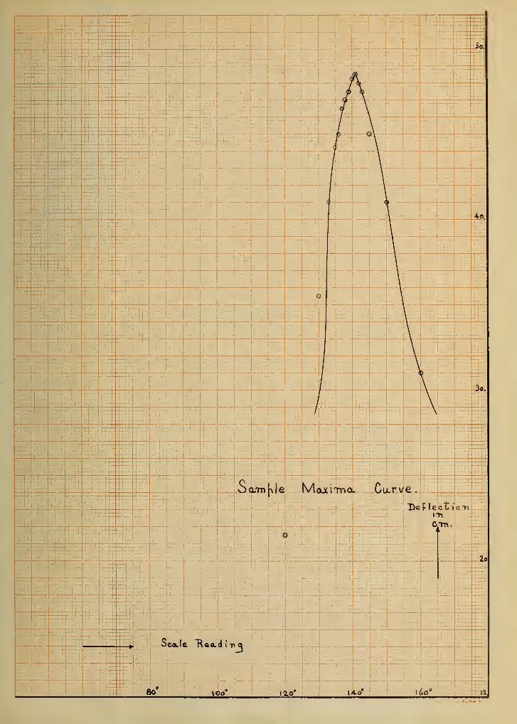
readings agreed.
169.5°170.0°171.0° Mean 170.4170.0° Maximum possible error 0.917 1.0°17 1.0°
The sharpness of the maxima can he £"een from the curve on the follow-
ing page. The denominator was determined from formula (37). Pour
independent determinations of this capacity gave numbers which were
proportional to
48.648.748.648.6
The error in data as accurate as the above leads, in the case of a di-
electric constant of about 3, to a maximum possible error of approxi-
mately 2.4$. Under* favorable conditions maximum data could be ob-
tained which was a little more accurate than the sample given. It
seems reasonable, in the case of low dielectric constants, to estimate
the maximum possible error as about 2</c. The reading of C f seemed to
change slightly from day ""O day, as if it depended to 3ome extent upon
the batteries to which the induction coil was connected. If tbis coul
be avoided, and it probably would be by using a quenched spark, C 1
could be determined a great many times and the mean taken as accurate.
If this were done the maximum possible error would be about \fc. In
these error estimations the calibration curve has been assumed correct
The electrometer was working perfectly when the calibration data was
taken. The curve being an average of many points is probably more
accurate than any one of the individual points.
Errors due to the liquid being conducting and thus decreasing
the maxima were avoided by placing a very large capacity (! micro-
farad) in series with the cone. This overcame conduction entirely
and did not change the capacity of the cone, as has been shown by
equation ( I"7 ) .
The maxima were kept large, never less than 50 cm., to insure
their accurate determination. The intensity of the maxima could be
regulated by advancing or withdrawing the secondary inductance from
the primary coil. In general the coils were never closer than 5 cm.I
The method is very sensitive to capacity changes. The near
presence of the body would change the maximum points very noticeably.
To avoid such errors all the apparatus except tha induction coil and
galvanometer was placed in a grounded metal box. So protected the
maxima were independent of outside influences.
To measure substances of higher dielectric constant more capacity
had to be put in the secondary and in order to tune with the primary
the inductance of the primary had to be increased. It was found under
these conditions that the maxima could not be determined as accurately
as with the lower capacity. Thu3 this method fails to give accurate
esults for substances which have high dielectric constants.
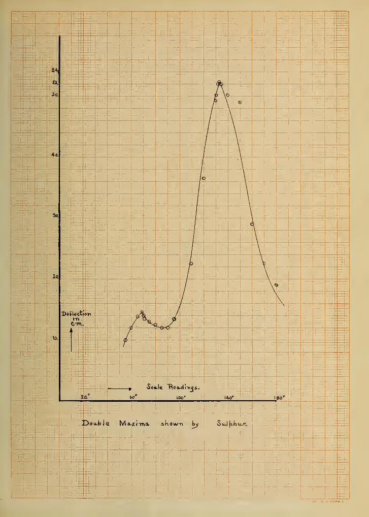
The study of a sulphur slab brought out an interesting phenomena
In attempting to tune, two distinct maxima were observed. The first
was small but very noticeable and the second large. The curve on the
next page represents the data taken upon this slab. Overtones in
3lectric resonance have been demonstrated. In this case the dielectric
constant computed from the first weak maximum is the proper value for
3ulphur and the one computed from the large maximum is much too low.
To justify taking the small maxima as the fundamental it must be as-
sumed that the first harmonic is more intense than the fundamental.
28
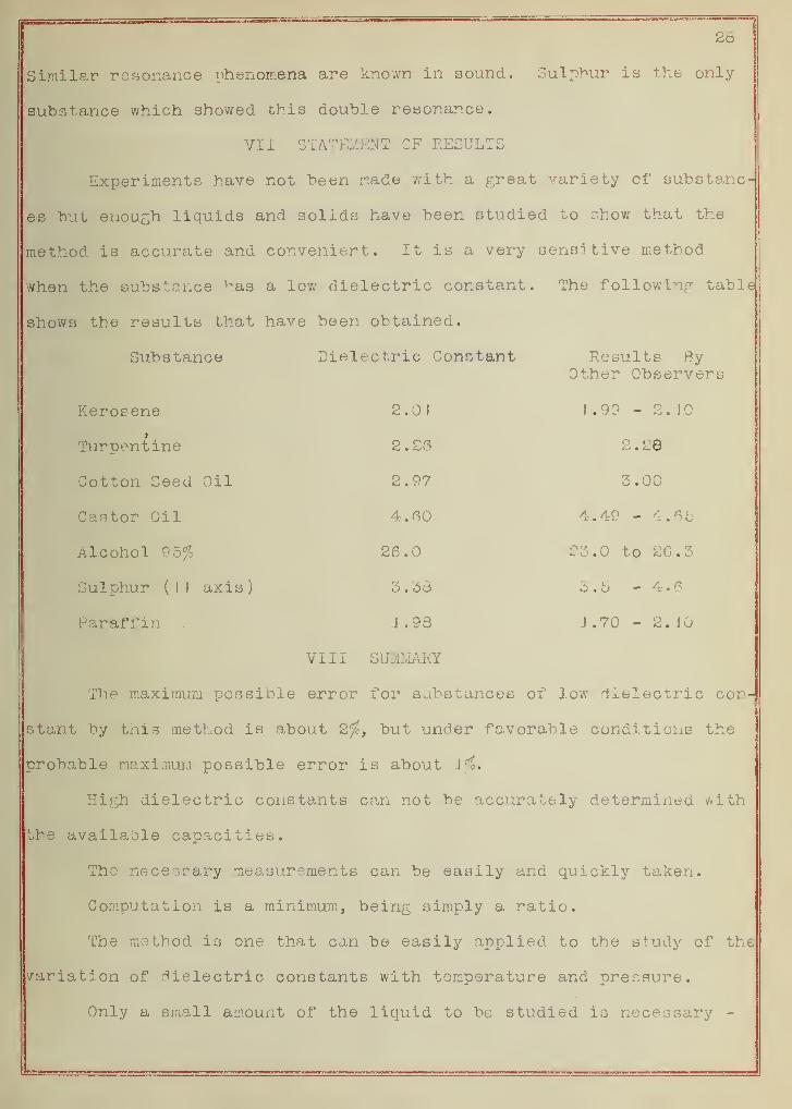
Similar resonance phenomena are known in sound. Sulphur is the only
substance which showed this double resonance.
VII STATEMENT OF RESULTS
Experiments have not been made with a great variety of substanc-
es but enough liquids and solids have been studied to show that the
method is accurate and convenient. It is a very sensitive method
when the substance ^as a low dielectric constant. The following table
shows the results that have been obtained.
Substance Dielectric Constant Results ByOther Observers
Kerosene 2.0J 1.99 - 2. JO
Turpentine 2.26 2.28
Cotton Seed Oil 2.97 3.00
Castor Oil 4.60 4.49 - 4.65
Alcohol 95^ 26.0 23.0 te 2C.3
Sulphur (II axis) 3.38 3.5-4.6
Paraffin . J .98 1.70 - 2.10
VIII SUMMARY
The maximum possible error for substances of low dielectric con
stant by this method is about 2%, but under favorable conditions the
probable maximum possible error is about K?.
High dielectric constants can not be accurately determined with
the available capacities.
The necessary measurements can be easily and quickly taken.
Computation is a minimum, being simply a ratio.
The method is one that can be easily applied to the study of the
variation of dielectric constants with temperature and pressure.
Only a small amount of the liquid to be studied is necessary -
I
29
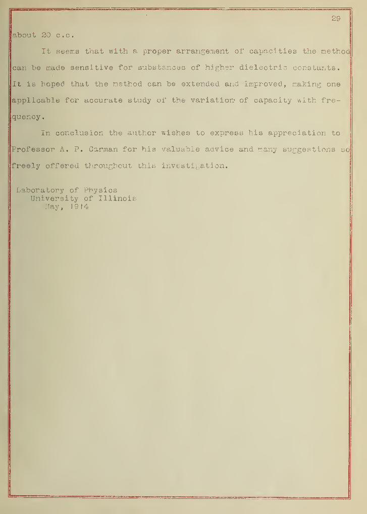
about 20 c.c.
It seems that with a proper arrangement of capacities the method
can be made sensitive for substances of higher dielectric constants.
It is bopecl that the method can be extended and improved, making one
applicable for accurate study of the variation- of capacity with fre-
quency .
In conclusion the author wishes to express his appreciation to
Professor A. P. Carman for his valuable advice and many suggestions so
freely offered throughout this investigation.
Laboratory of PhysicsUniversity of Illinois.
May, 19 14
mBm.