Embed Size (px)
Citation preview
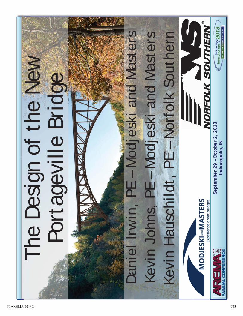
“The Design of the New Portageville Bridge”
Daniel B. Irwin, P.E.Modjeski and Masters, Inc
100 Sterling Parkway, Suite 302Mechanicsburg, PA 17050
(717)[email protected]
Kevin W. Johns, P.E.Modjeski and Masters, Inc
100 Sterling Parkway, Suite 302Mechanicsburg, PA 17050
(717)[email protected]
Kevin G. Hauschildt, P.E.Norfolk Southern Corporation
1200 Peachtree Street, NE, Box 142Atlanta, GA 30309
(404)[email protected]
(3,235 Words)
ABSTRACT
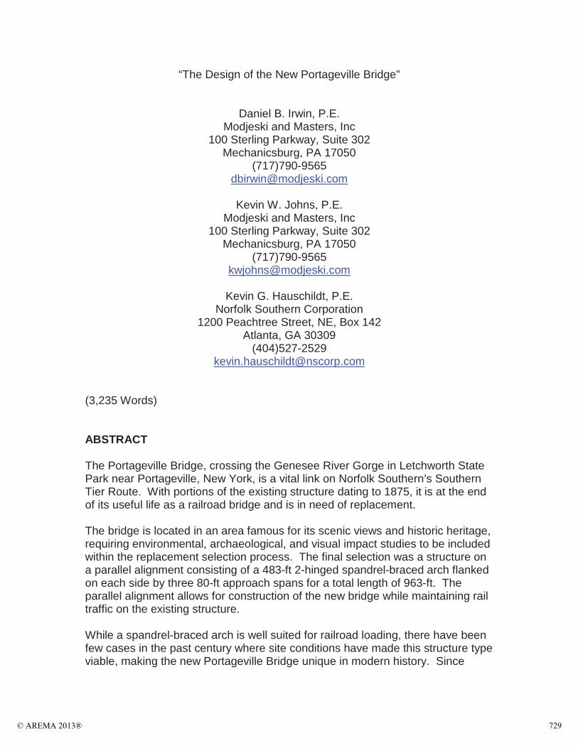
The Portageville Bridge, crossing the Genesee River Gorge in Letchworth State Park near Portageville, New York, is a vital link on Norfolk Southern’s Southern Tier Route. With portions of the existing structure dating to 1875, it is at the end of its useful life as a railroad bridge and is in need of replacement.
The bridge is located in an area famous for its scenic views and historic heritage, requiring environmental, archaeological, and visual impact studies to be included within the replacement selection process. The final selection was a structure on a parallel alignment consisting of a 483-ft 2-hinged spandrel-braced arch flanked on each side by three 80-ft approach spans for a total length of 963-ft. The parallel alignment allows for construction of the new bridge while maintaining rail traffic on the existing structure.
While a spandrel-braced arch is well suited for railroad loading, there have been few cases in the past century where site conditions have made this structure type viable, making the new Portageville Bridge unique in modern history. Since
© AREMA 2013® 729
AREMA does not fully cover structures of this type, guidance from previous spandrel-braced railroad arches as well as engineering judgment was required in order to design the structure not only for typical Cooper E-80 loading, but for thermal stresses and increased wind stresses from double-stack loading.
The new Portageville Bridge will serve well not only as a long-lasting freight-rail structure, but as a proud centerpiece for Norfolk Southern and a fitting backdrop to the scenic Genesee River Gorge for generations to come.
BACKGROUND
Site Description
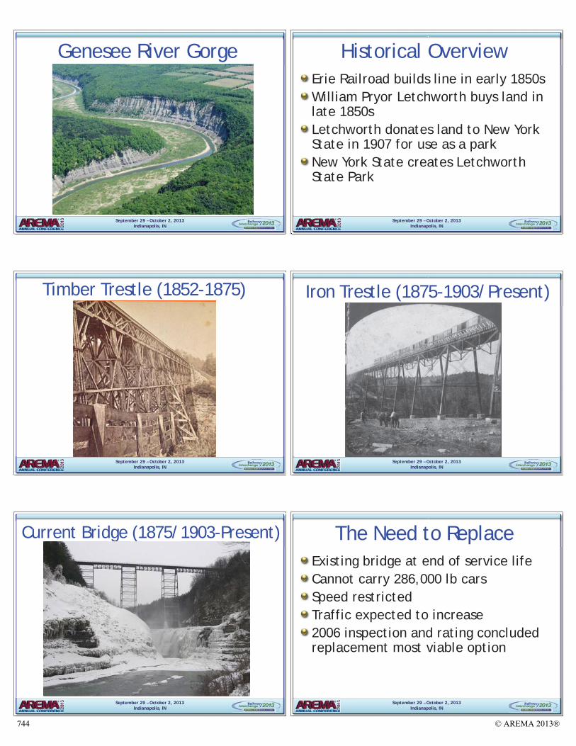
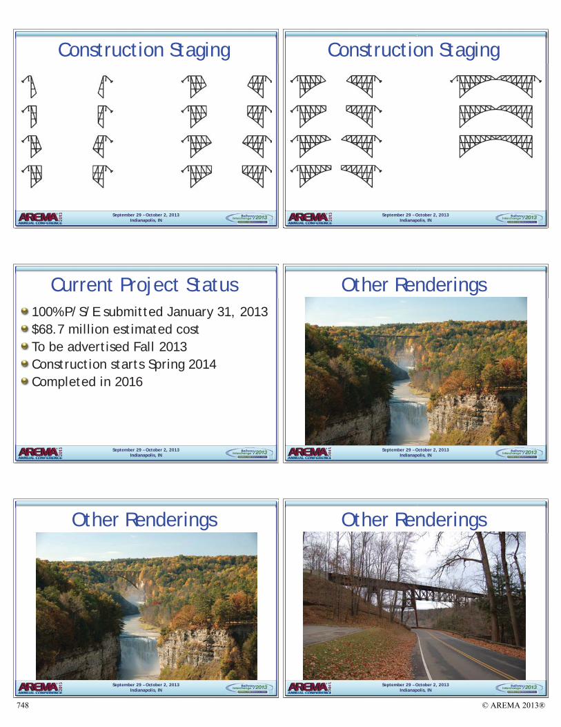
Western New York State is home to the Genesee River, which flows north from Pennsylvania, ultimately emptying into Lake Ontario near Rochester, New York. Near the town of Portageville, New York, the Genesee flows through a deep gorge, often referred to as the “Grand Canyon of the East.”
In the early 1850s, the Erie Railroad built a line through this region, crossing the gorge on a high timber trestle. In the late 1850s, William Pryor Letchworth, impressed by the scenic beauty of the region, purchased land in and around the gorge, ultimately leaving it to the State of New York for use as a park in 1907. Throughout the early 20th century, the park, named Letchworth State Park in honor of its donor, was developed and expanded. Currently it hosts over a million visitors a year that come for the scenery, including three large waterfalls in the Genesee River.
Historical Overview of Existing Structure
Original Timber Bridge
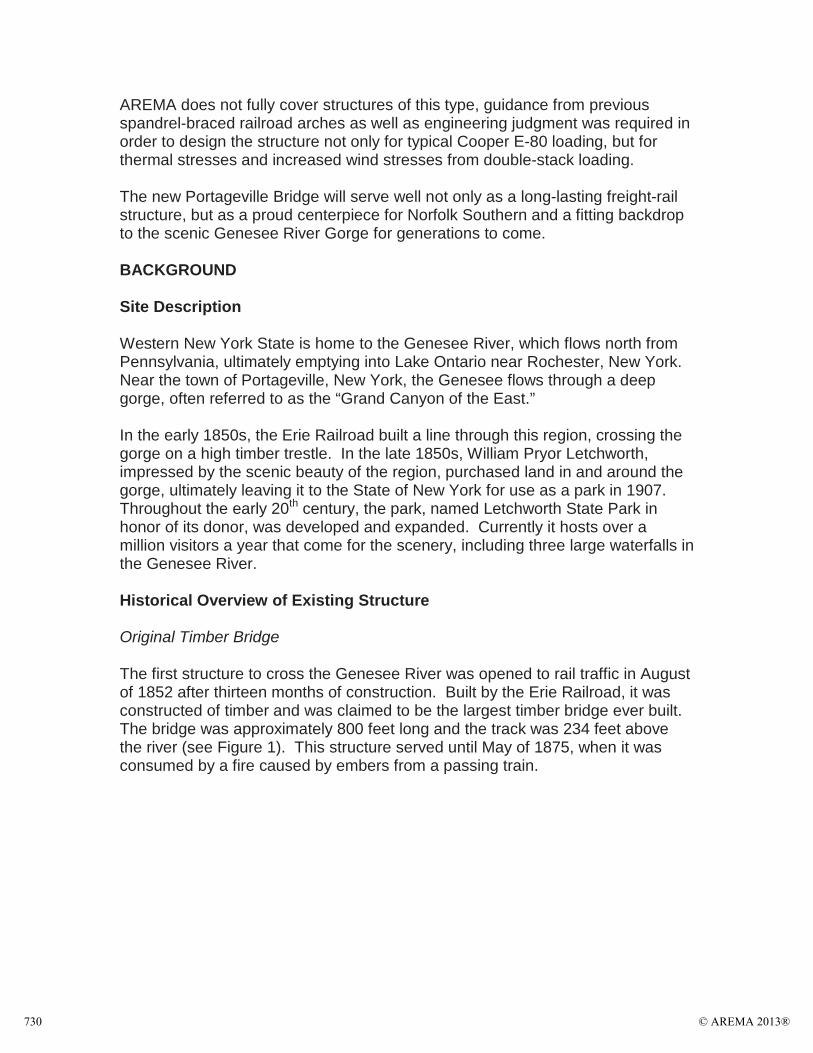
The first structure to cross the Genesee River was opened to rail traffic in August of 1852 after thirteen months of construction. Built by the Erie Railroad, it was constructed of timber and was claimed to be the largest timber bridge ever built.The bridge was approximately 800 feet long and the track was 234 feet above the river (see Figure 1). This structure served until May of 1875, when it was consumed by a fire caused by embers from a passing train.
© AREMA 2013®730
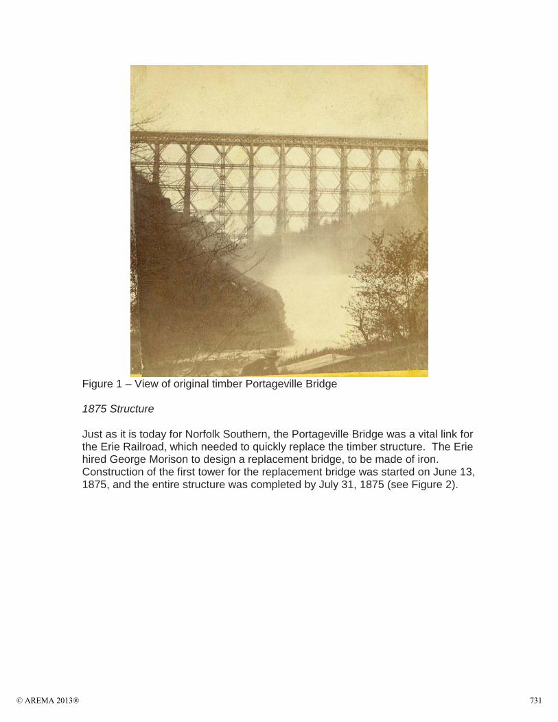
Figure 1 – View of original timber Portageville Bridge
1875 Structure
Just as it is today for Norfolk Southern, the Portageville Bridge was a vital link for the Erie Railroad, which needed to quickly replace the timber structure. The Erie hired George Morison to design a replacement bridge, to be made of iron. Construction of the first tower for the replacement bridge was started on June 13, 1875, and the entire structure was completed by July 31, 1875 (see Figure 2).
© AREMA 2013® 731
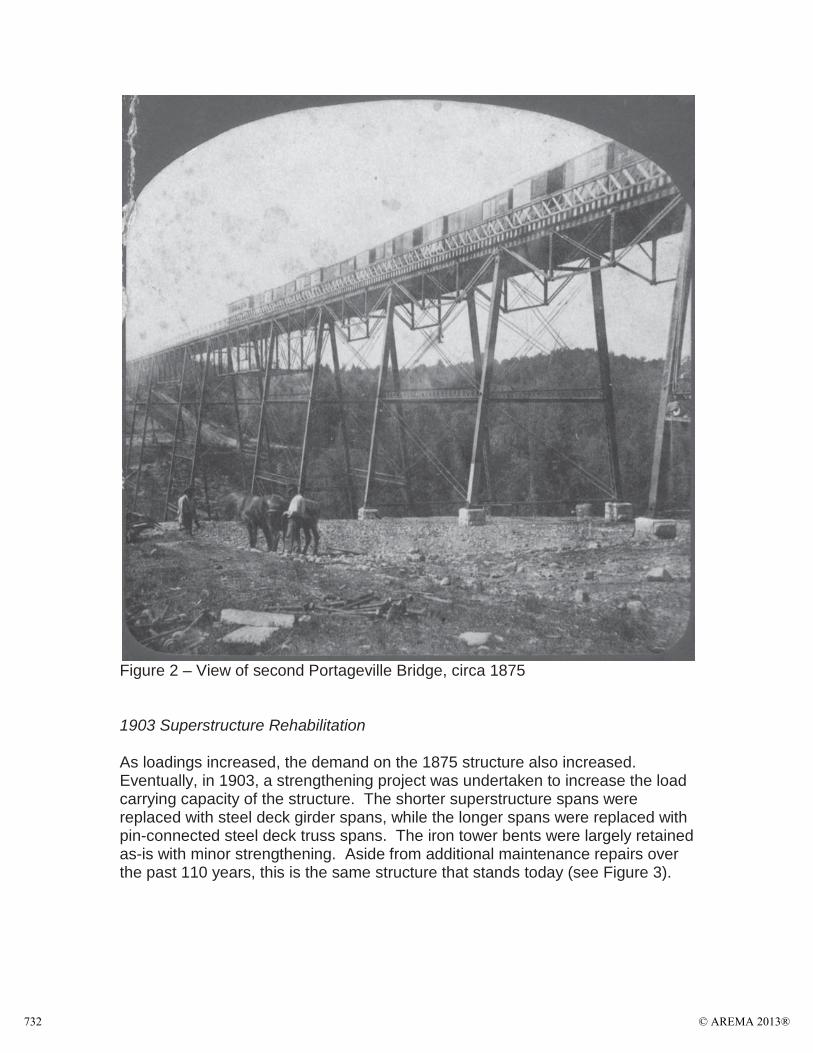
Figure 2 – View of second Portageville Bridge, circa 1875
1903 Superstructure Rehabilitation
As loadings increased, the demand on the 1875 structure also increased. Eventually, in 1903, a strengthening project was undertaken to increase the load carrying capacity of the structure. The shorter superstructure spans were replaced with steel deck girder spans, while the longer spans were replaced with pin-connected steel deck truss spans. The iron tower bents were largely retained as-is with minor strengthening. Aside from additional maintenance repairs over the past 110 years, this is the same structure that stands today (see Figure 3).
© AREMA 2013®732
Figure 3 – View of the present-day Portageville Bridge
THE NEED FOR REPLACEMENT
Condition/Analysis of Existing Structure
By the late 1990s, inspections and ratings of the existing Portageville Bridgeshowed it to be at the end of its service life. The condition of the bridge eventually became of such concern that Norfolk Southern engaged a consultant to start continuous electronic monitoring of the structure. Ratings showed that itis not capable of carrying the modern 286,000 lb cars and its condition subjects it to a speed restriction as well. In addition, anticipated expansion along the Southern Tier Route which the Portageville Bridge is located on, will likelyincrease traffic on the line. All of this combines to make the existing Portageville Bridge a weak link on the system.
Modjeski and Masters was first hired by Norfolk Southern in 1998 to begin preliminary studies on repair or replacement of the Portageville Bridge. In 2006 after another inspection and rating of the existing structure, Modjeski and Masters along with Norfolk Southern determined that replacement was the most viable option, and further studies were undertaken.
© AREMA 2013® 733
Replacement Study
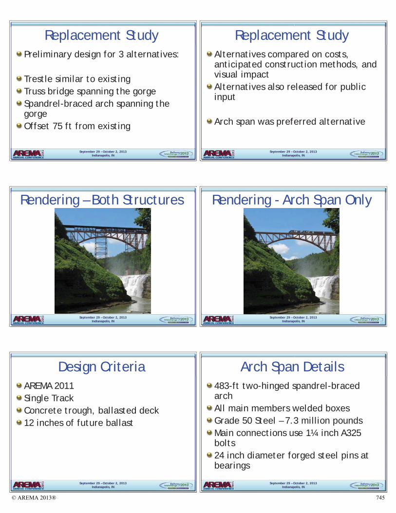
Several alternatives for a replacement bridge were studied by Modjeski and Masters and Norfolk Southern. Three alternatives were eventually selected for further study – a new trestle of a similar form to the existing bridge, a truss bridge spanning the gorge, and a spandrel-braced arch bridge spanning the gorge. The new bridge would be required to be built on a parallel alignment in order to maintain rail traffic at all times during the project.
Modjeski and Masters performed preliminary designs for the three alternatives. In addition to the preliminary designs, quantities and construction costs were estimated, as well as anticipated construction methods. Modjeski and Masters produced renderings of the alternatives showing them from various viewing angles. Renderings were produced both with and without the existing bridge present, since Norfolk Southern was willing to give the existing bridge to Letchworth State Park or another willing recipient once the new bridge is in service.
Norfolk Southern and Modjeski and Masters both realized that while it was essential for the railroad to choose the alternative that was best for it, it was also required by the environmental process to present the alternatives to the public to gather input. Although the railroad line through the area predates Letchworth State Park, the high visibility of the bridge coupled with the scenic nature of the area, along with the large number of visitors to the area made the need for public input apparent.
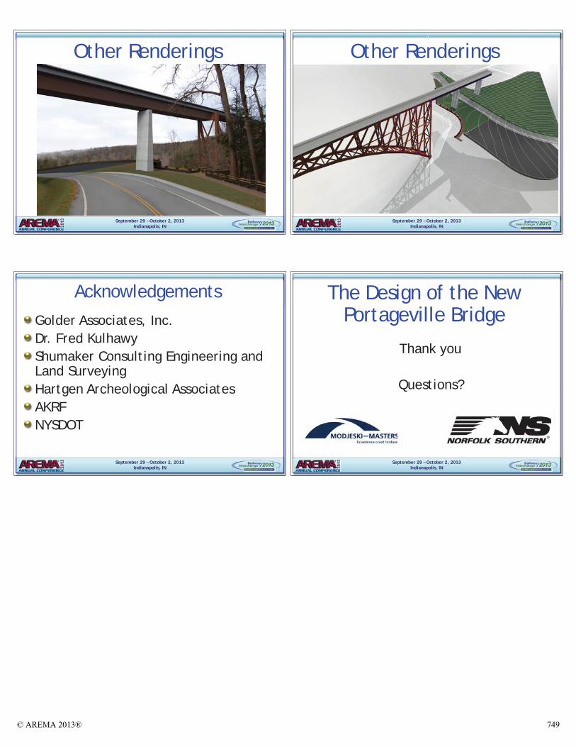
After evaluation by Norfolk Southern and public input, the preferred alternative was the spandrel-braced arch that will span the gorge (see Figures 4 and 5) with the existing bridge removed in its entirety except for a small portion of one tower which will remain as a form of historical recordation.
© AREMA 2013®734
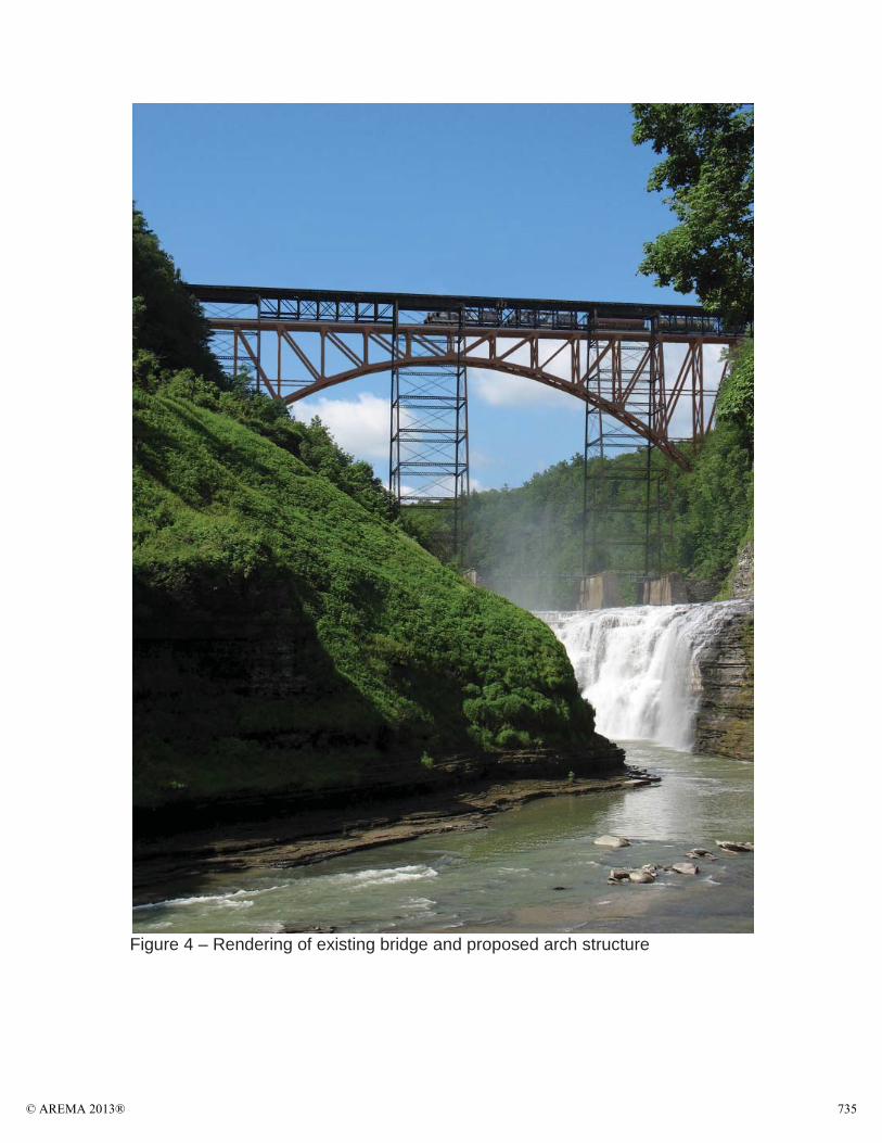
Figure 4 – Rendering of existing bridge and proposed arch structure
© AREMA 2013® 735
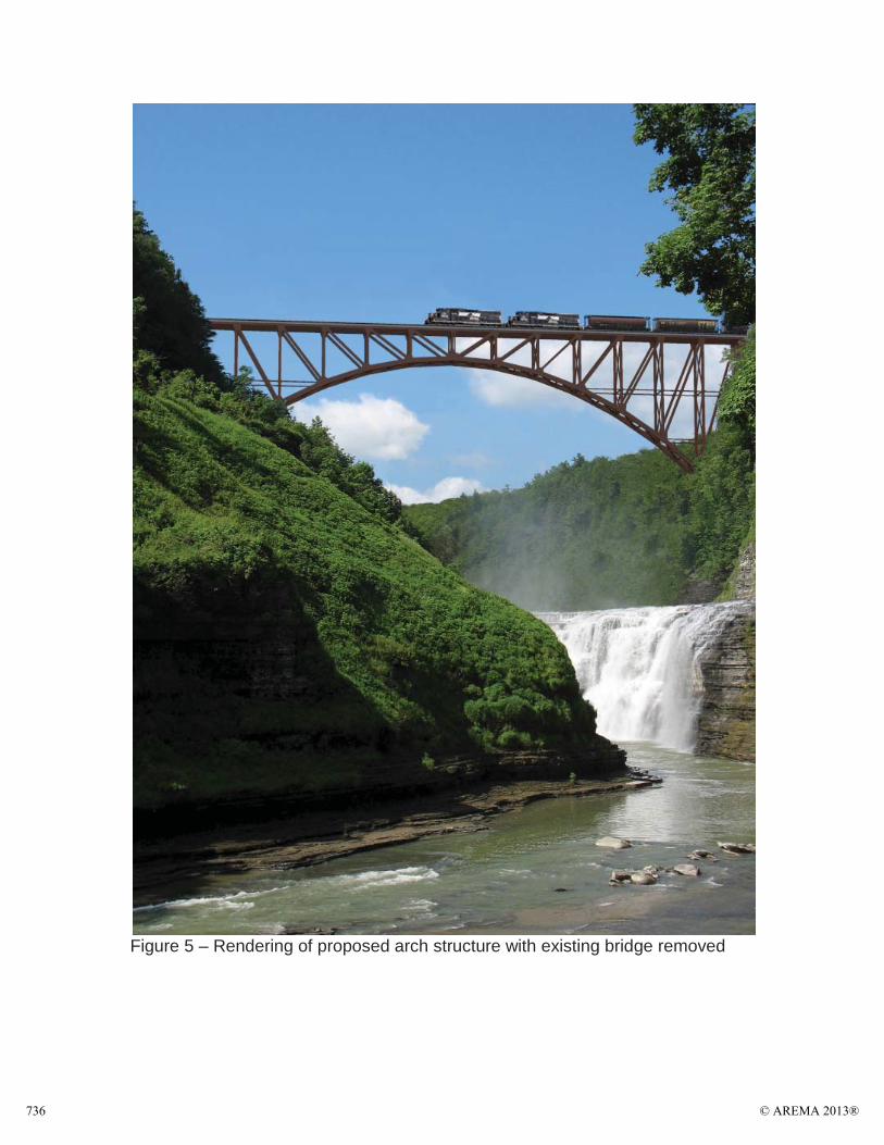
Figure 5 – Rendering of proposed arch structure with existing bridge removed
© AREMA 2013®736
IN-DEPTH LOOK AT PROPOSED STRUCTURE
General Information
The proposed structure consists of a 483 foot arch span flanked on each end by three 80 foot deck girder spans. The proposed bridge is offset on a parallel alignment 75 feet to the south of the existing structure.
The new structure was designed by Modjeski and Masters to AREMA 2011 guidelines. At the request of Norfolk Southern, the structure was designed with a6-beam cross section supporting a concrete trough and a ballasted deck. In addition, the structure was designed for 12 inches of future ballast, also at the request of Norfolk Southern.
Arch Span Details
The centerpiece of the new Portageville Bridge is its arch span. The arch is a two-hinged spandrel-braced type, with a span length of 483 feet. At the skewbacks, the distance from the centerline of the top chord to the pin is 148 feet, at the centerline of the span, the distance from the centerline of the top chord to the centerline of the arch rib is 25 feet. The two arch ribs are at 28 foot centers. Panel length is 34 feet 6 inches, with 14 panels giving 483 feet.
All main members are welded box shapes, with the arch rib measuring 4 feet 8inches deep by 3 feet wide, the top chord and diagonal members measuring 3 feet square, and vertical members measuring 2 feet 8 inches deep and 3 feet wide. The sway frames and bottom laterals are welded I-shapes, and the top laterals are rolled WT-shapes. All steel is Grade 50, and the final quantityestimate calculated that the arch span contains approximately 7.3 million pounds of steel.
All main member connections are comprised of 1.25 inch diameter A325 bolts. Connections are made with gusset plates, which were designed utilizing the latest research regarding gusset design and theory.
The arch ribs bear on 24 inch diameter forged steel pins that connect to cast steel bearing shoes that bear on concrete skewbacks founded on bedrock. The bearing shoes are 9 feet by 10 feet in plan view in order to provide adequate bearing area to stay below AREMA allowable bearing stresses.
The maximum compression force in an arch rib is approximately 6100 kips,which comes from a combination of dead load, 12 inches of future ballast, live load, maximum temperature, wind on the loaded structure, braking force, and a lateral equipment force.
© AREMA 2013® 737
Suggested Construction Methods
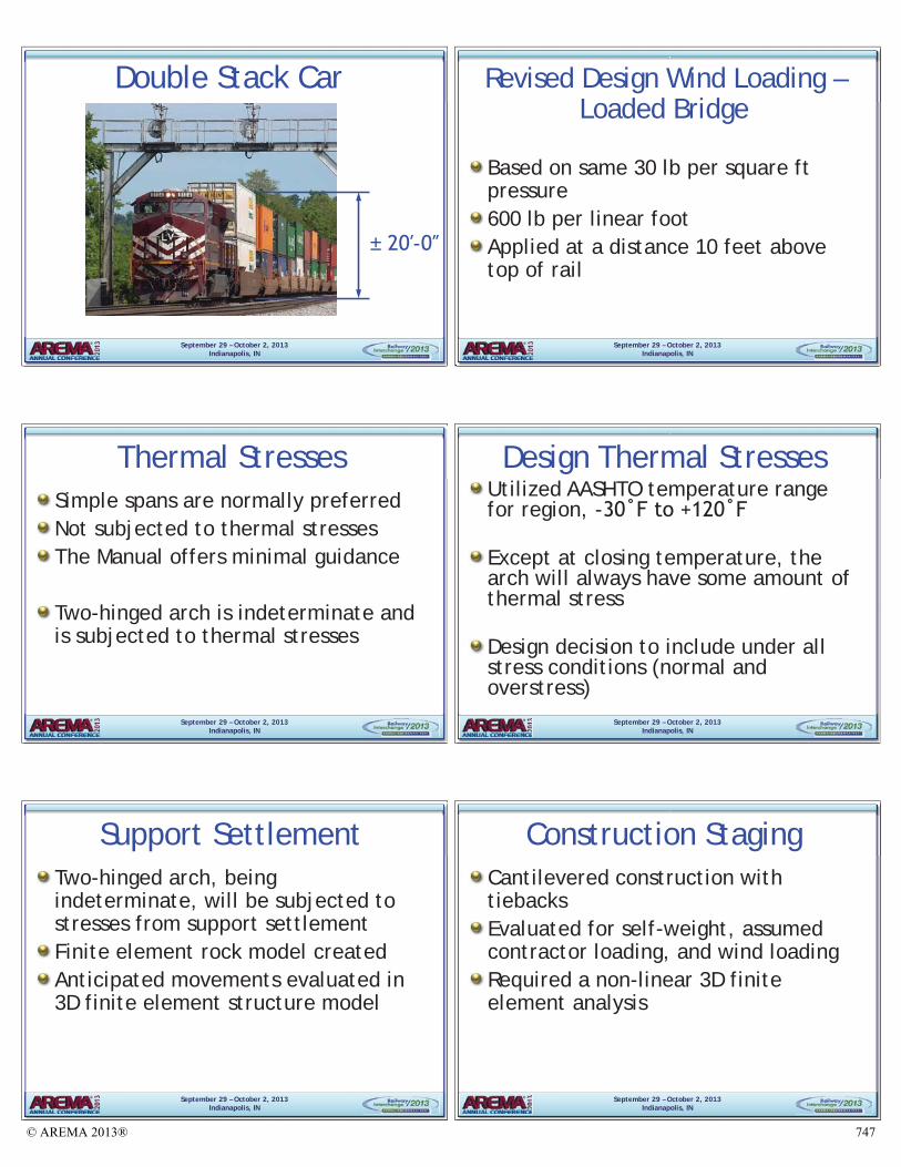
Modjeski and Masters, in proposing a spandrel braced arch, researched the methods historically used to construct these structures. The method most commonly used involved constructing the two halves of the arch as cantilevers in a stick-built manner from each gorge face until they met in the middle, at which point the cantilevers would be joined and the bridge would begin to function as an arch. In order to accomplish this, temporary tiebacks would be constructed to support the cantilever halves, and then were released upon joining the cantilevers. This method is possible due to the fact that a spandrel braced arch coupled with the temporary tiebacks is a self-supporting structure when cantilevered.
Upon examining the site conditions and constraints, Modjeski and Masters determined that using this method would be advantageous for the new Portageville Bridge. It avoids the need for any falsework in the river below, which would be difficult to construct with the limited access to the area, and would be equally as difficult to accomplish within the environmentally sensitive area of the Genesee River gorge. Therefore, with no need for falsework and a minimal footprint, Modjeski and Masters recommended the cantilevered tieback method as the suggested method of construction.
DESIGN CHALLENGES
Site/Civil Constraints and Challenges
The first challenges that Modjeski and Masters needed to overcome involved the job site itself. In order to stay as much within their existing right-of-way as possible, the 75 foot offset from Norfolk Southern’s existing bridge was established. After laying out the new track alignment and profile which will allow for a 35 MPH operating speed, and inserting the proposed structure into the topography, it became apparent that excavation for the arch skewbacks would interfere with an existing access road into Letchworth State Park.
As a solution, Modjeski and Masters realigned the access road, eliminating a dangerous hairpin curve, and provided a parking lot for park patrons that is larger than what currently exists.
Wind Loading for Double Stack Equipment
The commentary, Section 9.1.3.7, of Chapter 15 of AREMA, “Wind Forces on Loaded Bridge,” states in Subpart b. that “The recommended use of 300 lb per linear foot…is adequate for use on lines where double stack equipment is not operated. The engineer should consider increasing this force in areas where double stack equipment…operates…”
© AREMA 2013®738
Modjeski and Masters contacted Norfolk Southern regarding the usage of double stack equipment on the Portageville Bridge, and received confirmation that double stack trains are run on the line, and therefore felt it would be prudent to design the new bridge with an increased wind force.
Additional reading of Chapter 15, Section 9.1.3.7, in Subpart a. reveals that the wind loading is based on a 30 lb per square foot pressure, which is the pressure produced by the maximum wind under which it was assumed that a train would operate.
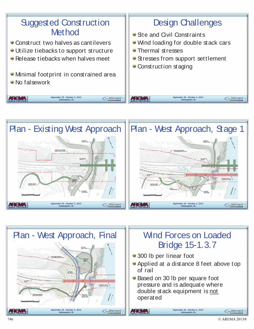
Research into the double stack equipment currently used on railroads showed that the tallest car normally used is a depressed center car with an overall height of 20 feet 2 inches. Modjeski and Masters utilized this height car along with the 30 lb per square foot pressure and determined that a reasonable and conservative wind loading would be 600 lb per linear foot acting at 10 feet above the rail.
Thermal Stresses
For a multitude of reasons, simple span structures are the desired structure type for railroads. One of the positive aspects of a simple span is that it does not see induced stresses from temperature loading. As a result, there does not need to be much guidance within AREMA in terms of thermal stresses. The two-hinged arch span of the new Portageville Bridge will, however, see thermal stresses due to its indeterminacy.
Modjeski and Masters and Norfolk Southern decided that the arch span should be designed for the temperature range defined by AASHTO for the region that the Portageville Bridge is located in, namely from -30 degrees Fahrenheit to +120 degrees Fahrenheit. It was assumed that the two halves of the span would be joined, and therefore become indeterminate and subjected to thermal stresses, at +60 degrees Fahrenheit.
A second challenge regarding thermal stresses was how to include them within the design, that is, whether to view them under all stress conditions or just as an overstress condition. Other than when the arch span is at the exact temperature when it was closed, there will always be some magnitude of thermal stresses in the arch members. Therefore, the conservative decision was made to view thermal stresses under all stress conditions.
Induced Stresses from Support Settlement
As mentioned in the previous section, the preference for railroads is to have simple span structures. A second positive aspect of a simple span is that support movements will not induce stresses into the structure. An indeterminate structure, conversely, will see induced stresses from support movements. As a
© AREMA 2013® 739
result, the arch span was evaluated to determine the effect of the anticipated support movements under the design loading.
Golder Associates created a finite-element rock model to determine the magnitude of the support movements under the design loading. The rock model included pertinent data gathered from test borings including rock type, modulus of elasticity, and the direction of the rock layers.
The predicted settlement from the finite-element rock model was given to Modjeski and Masters for evaluation in a 3-dimensional finite-element model of the arch span. Ultimately, it was found that the magnitudes of the induced stresses were small enough to not require increasing member sizes.
Construction Staging Analysis
The cantilevered construction method proposed to construct the arch span, described previously and while used successfully in the past, still needed to be evaluated for feasibility. Modjeski and Masters determined that the structureshould be evaluated for various combinations of self weight, contractor loading, and wind loading. The analysis was carried out with a non-linear 3-dimensional finite-element model. Nonlinearity was required because at the closure stage for the arch, the tiebacks are removed, requiring forces to redistribute as the structure stops functioning as two cantilevers, and starts functioning as an arch.
Modjeski and Masters first had to determine what a reasonable, conservative approximation of contractor loading would be. And the following assumptions were made:
Pieces of the arch will have to be ferried along it to the end of the cantilever and lowered into place. The heaviest member’s weight per foot was used and applied as a line load to each arch line, assuming that both pieces would be moved out simultaneously. This load was applied to each arch line for every stage of construction2000 lb was applied at each main panel point as an assumed load for a platform for bolting crewsA traveler crane will be needed at the tip of the cantilever to lower pieces into place. A 50 ton capacity Link-Belt crane was used for reference, with one such crane being approximately 72.5 kips and another being approximately 97 kips in operating weight. With this reference, 100 kips was applied at the tip of the cantilever at each construction stage to represent the crane.
In the cantilever stage, the full design wind loading was applied to the structure at each construction stage to analyze the structure. In order to obtain an envelope of minimums and maximums, in addition to self weight, the structure was analyzed with both wind and contractor loading, and just wind alone, assuming
© AREMA 2013®740
that if there are high winds the contractor will likely remove all equipment from the bridge, if given enough warning.
CURRENT PROJECT STATUS
Timeline for Bids and Construction
Modjeski and Masters submitted 100% plans, specifications, and a cost estimate to Norfolk Southern on January 31, 2013. The final cost estimate for the project was approximately $68.7 million. Norfolk Southern intends to advertise the project for bids in late Fall 2013 to start construction in Spring 2014. Work on the new Portageville Bridge should be complete and carrying rail traffic in 2016.
SUMMARY AND CONCLUSIONS
Letchworth State Park in western New York State is famous for its scenic beauty,including the gorge that the Genesee River cuts through it. Crossing the gorge is the Portageville Bridge on Norfolk Southern’s Southern Tier Route. The current bridge at 110 years old is in need of replacement to handle modern rail loadings. Modjeski and Masters along with Norfolk Southern worked together to study various alternatives, and after selecting the most favorable, designed a replacement structure with its centerpiece being a 483 foot spandrel braced arch, spanning the gorge.
Throughout the design process, Modjeski and Masters was faced with and overcame several design challenges with the new Portageville Bridge including site/civil constraints, calculation of an increased wind loading for double stack cars, the calculation and inclusion of thermal stresses on the arch span, investigating induced stresses from support settlement, and analyzing stresses during construction staging.
Modjeski and Masters submitted 100% plans, specifications, and a cost estimate to Norfolk Southern on January 31, 2013. The job is anticipated to be bid in late Fall 2013 to start construction in Spring 2014 with a completion date in 2016.When completed, the new Portageville Bridge will serve as a proud landmark on Norfolk Southern’s system and should also be a fitting addition to the scenic environment that Letchworth State Park is famous for.
ACKNOWLEDGEMENTS
Golder Associates, IncDr. Fred KulhawyShumaker Consulting Engineering and Land SurveyingHartgen Archeological AssociatesAKRF
© AREMA 2013® 741
LIST OF FIGURES
Figure 1 – View of original timber Portageville BridgeFigure 2 – View of second Portageville Bridge, circa 1875Figure 3 – View of present-day Portageville BridgeFigure 4 – Rendering of existing bridge and proposed arch structureFigure 5 – Rendering of proposed arch structure with existing bridge removed
© AREMA 2013®742
Sept
embe
r 29
–O
ctob
er 2
, 20
13In
dian
apol
is,
IN
The
Desi
gn o
f th
e N
ew
Port
agev
ille
Brid
ge
Dan
iel I
rwin
, PE
–M
odje
ski a
nd M
aste
rsKe
vin
John
s, P
E –
Mod
jesk
i and
Mas
ters
Kevi
n H
ausc
hild
t, P
E –
Nor
folk
Sou
ther
n
© AREMA 2013® 743
September 29 – October 2, 2013Indianapolis, IN
Genesee River Gorge
September 29 – October 2, 2013Indianapolis, IN
Historical OverviewErie Railroad builds line in early 1850sWilliam Pryor Letchworth buys land in late 1850sLetchworth donates land to New York State in 1907 for use as a parkNew York State creates Letchworth State Park
September 29 – October 2, 2013Indianapolis, IN
Timber Trestle (1852-1875)
NameTitleCompany Name
September 29 – October 2, 2013Indianapolis, IN
Iron Trestle (1875-1903/Present)
NameTitleCompany Name
September 29 – October 2, 2013Indianapolis, IN
Current Bridge (1875/1903-Present)
NameTitleCompany Name
g (
aaaaaaaaaaaaaaaaaaaaaaaaaaaaaaaaaaaaaaaaaaaaaaaaaaaaaaaaaaaaaaaaaaaaaaaaaaaaaaaaaaaaamememememememememememememememememememememememememememememememememmememememmmememememememememmemmmmmmmeememmmemememememmmemmememmemememmeemmmmeemmmmmmmmemeemmemmeeemmeememeeemmmmmmmemetlttttltltltltltttltltltlttttltttltltltttttttttttttlttttttltttttttttttttttttttttttltttttttttttttttttttttlt eeeeeeeeeeeeeeeeeeeeeeeeeeeeeeoooooooooooooooooooooooooooooooooooooooooooooooooooooooooooooooooooooooooooooooooooooooooooooooooooooooooooooooooooooooooooooooooooooooooooooooooooooooompmpmpmpmpmpmpmpmpmpmpmpmpmpmpmpmpmpmpmpmpmpmpmppmpmpmpmpmpmpmpmpmpmpmpmpmmmpmmmmmmppmpmpmpmmpmmpmpmpmpmmpmpmpmpmpmpmmmpmpmmpmpmppmpmpmpmmpmmmmpmppppmpmmmpmppppmpmpmmmpmppppppmppmpmmppppppmpmpmpmppppmpmmpppmpmpmmppmmmmpmpmmmpmmmpmpppmpmppmppmmppppppppppppppppanaanaananananananananananananananananananananananaananananaananananananananaaaaaaaaananananaaaaaaaanaaaaaaanaanaaanannanaaanaananananaaaanananaananananaaaaaaaanaaaaaaaaaaaaaaaaaaaaannnanaanaanannnaannannaaaaaaaannnnnnnnaaaa yyyyyyyyyyyyyyyyyyyyyyyyyyyyyyyyyyyyyyyyyyyyyyyyyyyyyyyyyyyyyyyyyyyyyyyyyyyyyyyyyy NaNaNaNaNNNaNNaNaNaNaNNNaNNaNNaNaNNaNNaNaNaNNNaNNNaNaNaNNNaNNaNaNNNaNaNNNNaNNNNaNNNNaNNNNaNaNNaNaNaNNNNaNNNaNNNaNaNNNNaNaNNNNNNNNNNaNNNNNNNaNNNNNNNNNNNaNNNN mememmemmememmememememememememememememeeememememememmmmmmmeemeememeememmmmmemeemememememmeeeeemememeemmmeeemeemeeeememmemmmmmmmmmmmmmmmmmmmeeee
September 29 – October 2, 2013Indianapolis, IN
The Need to ReplaceExisting bridge at end of service lifeCannot carry 286,000 lb carsSpeed restrictedTraffic expected to increase2006 inspection and rating concluded replacement most viable option
© AREMA 2013®744
September 29 – October 2, 2013Indianapolis, IN
Replacement StudyPreliminary design for 3 alternatives:
Trestle similar to existingTruss bridge spanning the gorgeSpandrel-braced arch spanning the gorgeOffset 75 ft from existing
September 29 – October 2, 2013Indianapolis, IN
Replacement StudyAlternatives compared on costs, anticipated construction methods, and visual impactAlternatives also released for public input
Arch span was preferred alternative
September 29 – October 2, 2013Indianapolis, IN
Rendering – Both Structures
September 29 – October 2, 2013Indianapolis, IN
Rendering - Arch Span Only
September 29 – October 2, 2013Indianapolis, IN
Design CriteriaAREMA 2011Single Track Concrete trough, ballasted deck12 inches of future ballast
September 29 – October 2, 2013Indianapolis, IN
Arch Span Details483-ft two-hinged spandrel-braced archAll main members welded boxesGrade 50 Steel – 7.3 million poundsMain connections use 1¼ inch A325 bolts24 inch diameter forged steel pins at bearings
© AREMA 2013® 745
September 29 – October 2, 2013Indianapolis, IN
Suggested Construction Method
Construct two halves as cantileversUtilize tiebacks to support structureRelease tiebacks when halves meet
Minimal footprint in constrained areaNo falsework
September 29 – October 2, 2013Indianapolis, IN
Design ChallengesSite and Civil ConstraintsWind loading for double stack carsThermal stressesStresses from support settlementConstruction staging
September 29 – October 2, 2013Indianapolis, IN
Plan - Existing West Approach
September 29 – October 2, 2013Indianapolis, IN
Plan - West Approach, Stage 1
September 29 – October 2, 2013Indianapolis, IN
Plan - West Approach, Final
September 29 – October 2, 2013Indianapolis, IN
Wind Forces on Loaded Bridge 15-1.3.7
300 lb per linear footApplied at a distance 8 feet above top of railBased on 30 lb per square foot pressure and is adequate where double stack equipment is notoperated
© AREMA 2013®746
September 29 – October 2, 2013Indianapolis, IN
Double Stack Car
NameTitleCompany Name
± -
September 29 – October 2, 2013Indianapolis, IN
Revised Design Wind Loading – Loaded Bridge
Based on same 30 lb per square ft pressure600 lb per linear footApplied at a distance 10 feet above top of rail
September 29 – October 2, 2013Indianapolis, IN
Thermal StressesSimple spans are normally preferredNot subjected to thermal stressesThe Manual offers minimal guidance
Two-hinged arch is indeterminate and is subjected to thermal stresses
September 29 – October 2, 2013Indianapolis, IN
Design Thermal StressesUtilized AASHTO temperature range for region, -
Except at closing temperature, the arch will always have some amount of thermal stress
Design decision to include under all stress conditions (normal and overstress)
September 29 – October 2, 2013Indianapolis, IN
Support SettlementTwo-hinged arch, being indeterminate, will be subjected to stresses from support settlementFinite element rock model createdAnticipated movements evaluated in 3D finite element structure model
September 29 – October 2, 2013Indianapolis, IN
Construction StagingCantilevered construction with tiebacksEvaluated for self-weight, assumed contractor loading, and wind loadingRequired a non-linear 3D finite element analysis
© AREMA 2013® 747
September 29 – October 2, 2013Indianapolis, IN
Construction Staging
September 29 – October 2, 2013Indianapolis, IN
Construction Staging
September 29 – October 2, 2013Indianapolis, IN
Current Project Status100% P/S/E submitted January 31, 2013$68.7 million estimated costTo be advertised Fall 2013Construction starts Spring 2014Completed in 2016
September 29 – October 2, 2013Indianapolis, IN
Other Renderings
September 29 – October 2, 2013Indianapolis, IN
Other Renderings
September 29 – October 2, 2013Indianapolis, IN
Other Renderings
© AREMA 2013®748
September 29 – October 2, 2013Indianapolis, IN
Other Renderings
September 29 – October 2, 2013Indianapolis, IN
Other Renderings
September 29 – October 2, 2013Indianapolis, IN
Acknowledgements
Golder Associates, Inc.Dr. Fred KulhawyShumaker Consulting Engineering and Land SurveyingHartgen Archeological AssociatesAKRFNYSDOT
September 29 – October 2, 2013Indianapolis, IN
The Design of the New Portageville Bridge
Thank you
Questions?
© AREMA 2013® 749


![Welcome [] · Letchworth State Park. • Install an interpretive kiosk that would display text and photographs to document the history, design, and use of the Portageville Bridge](https://img.pdfslide.us/doc/110x75/5e3cad157281bd204d643aea/welcome-letchworth-state-park-a-install-an-interpretive-kiosk-that-would.jpg)