Embed Size (px)
Citation preview
The Design of Signal Generator based on Virtual Instrument
Zhang Hui1, a, Gao Ling2, b,YanNan Zhai3, b,Li Jun4, b
1,2,3,4Electrical and Electronic Teaching and Research Section ,Aviation University of Air Force
Changchun, 130022, China aemail:[email protected], bemail:[email protected]
Keywords: Virtual Signal Generator;LabVIEW; NlUSB-6009
Abstract. The paper design a Virtual Signal Generator based on Virtual Instrument,which can produce continuous adjustable amplitude and frequency signal .It’s contains of the most basic three waveform: sine wave, pulse wave and triangle wave. We design the signal generator by LabVIEW. Data acquisition is NIUSB-6009. By the measurement we can seen from function to output signal parameters of the virtual signal generator are similar as the results of actual measurement.
Introduction
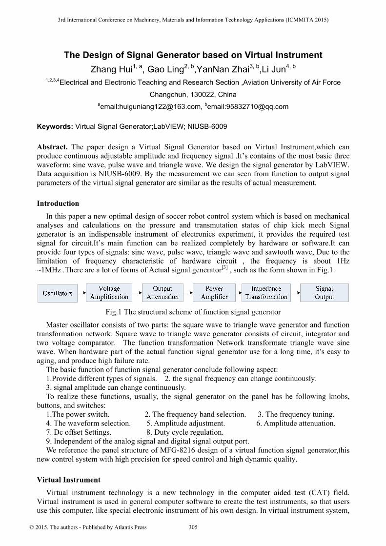
In this paper a new optimal design of soccer robot control system which is based on mechanical analyses and calculations on the pressure and transmutation states of chip kick mech Signal generator is an indispensable instrument of electronics experiment, it provides the required test signal for circuit.It’s main function can be realized completely by hardware or software.It can provide four types of signals: sine wave, pulse wave, triangle wave and sawtooth wave, Due to the limitation of frequency characteristic of hardware circuit , the frequency is about 1Hz ~1MHz .There are a lot of forms of Actual signal generator[3] , such as the form shown in Fig.1.
Fig.1 The structural scheme of function signal generator
Master oscillator consists of two parts: the square wave to triangle wave generator and function transformation network. Square wave to triangle wave generator consists of circuit, integrator and two voltage comparator. The function transformation Network transformate triangle wave sine wave. When hardware part of the actual function signal generator use for a long time, it’s easy to aging, and produce high failure rate.
The basic function of function signal generator conclude following aspect: 1.Provide different types of signals. 2. the signal frequency can change continuously. 3. signal amplitude can change continuously. To realize these functions, usually, the signal generator on the panel has he following knobs,
buttons, and switches: 1.The power switch. 2. The frequency band selection. 3. The frequency tuning. 4. The waveform selection. 5. Amplitude adjustment. 6. Amplitude attenuation. 7. Dc offset Settings. 8. Duty cycle regulation. 9. Independent of the analog signal and digital signal output port. We reference the panel structure of MFG-8216 design of a virtual function signal generator,this
new control system with high precision for speed control and high dynamic quality.
Virtual Instrument
Virtual instrument technology is a new technology in the computer aided test (CAT) field. Virtual instrument is used in general computer software to create the test instruments, so that users use this computer, like special electronic instrument of his own design. In virtual instrument system,
3rd International Conference on Machinery, Materials and Information Technology Applications (ICMMITA 2015)
© 2015. The authors - Published by Atlantis Press 305
the hardware is to solve the input and output signal, the software is the key, Any user can rewrite the software to change the function of the instrument, so we say software is the instrume. Virtual instrument technology can be applied to many signal processing method of measurement, completely breaking the traditional instruments of the framework. The user can according to their own needs, design of instrument system, meet the diversity of needs[1].
The design of the Virtual Signal Generator
Based on the need for electronics experimental teaching, We design the virtual function signal generator, which can produce continuous adjustable amplitude and frequency .It’s contains of the most basic three waveform: sine wave, adjustable duty ratio of pulse wave, triangle wave. The frequency of the signal theoretically can cover the entire spectrum, however, limited by computer performance and the sampling frequency of acquisition card, the frequency could not unlimited increase. Signal acquisition card amplitude is limited for of maximum output voltage, less of the upper limit and lower limit value. In this design, NlUSB-6009 output signal range is 0-5 V.
The composition of virtual function signal generator nterface Card Device Driver Virtual function signal generator by the PC machine, multi-function data acquisition card and
software. We design the signal by LabVIEW graphical programming language , the signal output by the acquisition card.
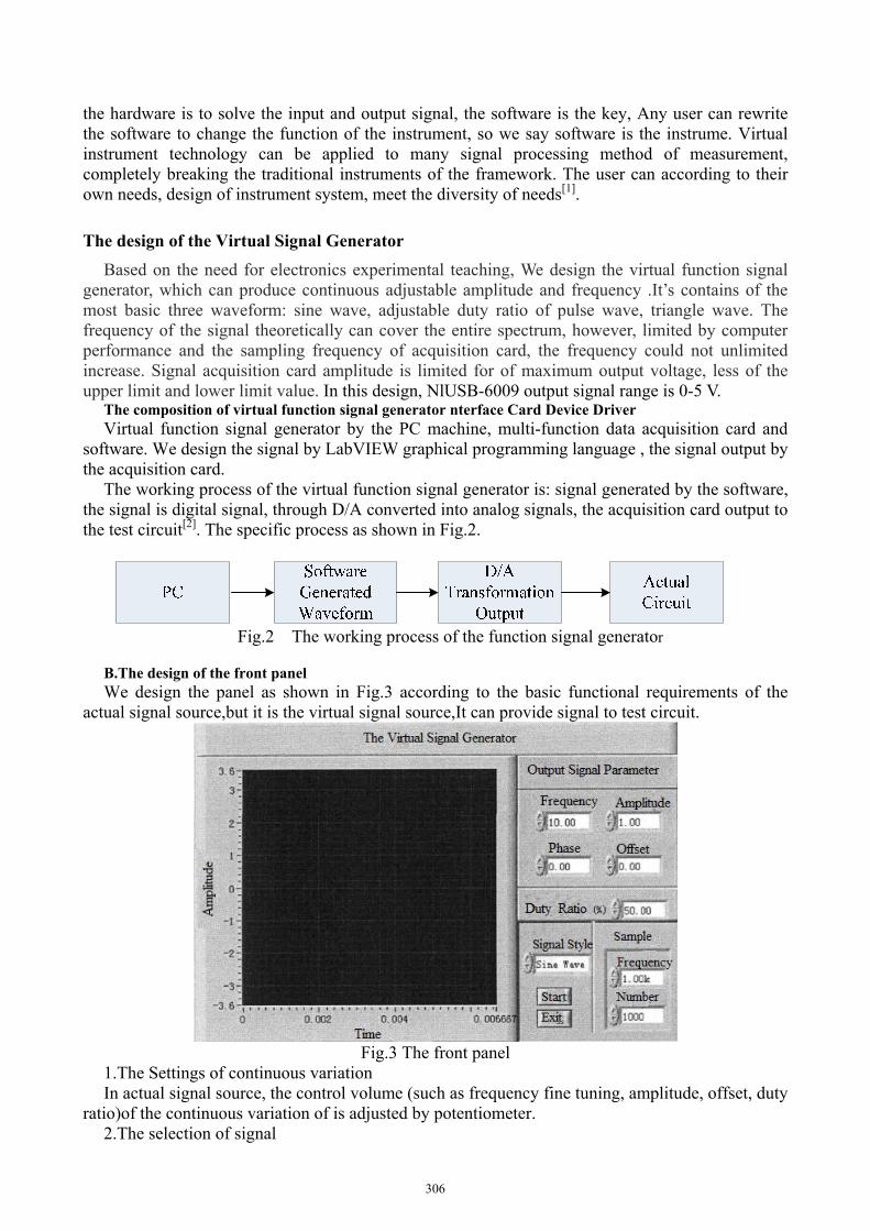
The working process of the virtual function signal generator is: signal generated by the software, the signal is digital signal, through D/A converted into analog signals, the acquisition card output to the test circuit[2]. The specific process as shown in Fig.2.
Fig.2 The working process of the function signal generator
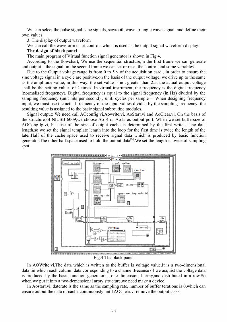
B.The design of the front panel We design the panel as shown in Fig.3 according to the basic functional requirements of the
actual signal source,but it is the virtual signal source,It can provide signal to test circuit.
Fig.3 The front panel
1.The Settings of continuous variation In actual signal source, the control volume (such as frequency fine tuning, amplitude, offset, duty
ratio)of the continuous variation of is adjusted by potentiometer. 2.The selection of signal
306
We can select the pulse signal, sine signals, sawtooth wave, triangle wave signal, and define their own values.
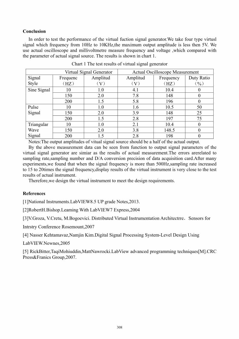
3. The display of output waveform We can call the waveform chart controls which is used as the output signal waveform display. The design of black panel The main program of Virtual function signal generator is shown in Fig.4. According to the flowchart, We use the sequential structure,in the first frame we can generate
and output the signal, in the second frame we can set or reset the control and some variables . Due to the Output voltage range is from 0 to 5 v of the acquisition card , in order to ensure the
sine voltage signal in a cycle are positive,on the basis of the output voltage, we drive up to the same as the amplitude value, in this way, the set value is not greater than 2.5, the actual output voltage shall be the setting values of 2 times. In virtual instrument, the frequency is the digital frequency (normalized frequency), Digital frequency is equal to the signal frequency (in Hz) divided by the sampling frequency (unit hits per second) , unit: cycles per sample[4]. When designing frequency input, we must use the actual frequency of the input values divided by the sampling frequency, the resulting value is assigned to the basic signal subroutine modules.
Signal output: We need call AOconfig.vi,Aowrite.vi, AoStart.vi and AoClear.vi. On the basis of the structure of NlUSB-6009,we choose Ao14 or Ao15 as output port. When we set buffersize of AOCongflg.vi, because of the size of output cache is determined by the first write cache data length,so we set the signal template length into the loop for the first time is twice the length of the later.Half of the cache space used to receive signal data which is produced by basic function generator.The other half space used to hold the output data[5].We set the length is twice of sampling spot.
Fig.4 The black panel
In AOWrite.vi,The data which is written to the buffer is voltage value.It is a two-dimensional data ,in which each column data corresponding to a channel.Because of we acquist the voltage data is produced by the basic function generator is one dimensional array,and distributed in a row.So when we put it into a two-demensional array structure,we need make a device.
In Aostart.vi, daterate is the same as the sampling rate, number of buffer terations is 0,which can ensure output the data of cache continuously until AOClear.vi remove the output tasks.
307
Conclusion
In order to test the performance of the virtual fuction signal generator.We take four type virtusl signal which frequency from 10Hz to 10KHz,the maximum output amplitude is less then 5V. We use actual oscilloscope and millivoltmetre measure frequency and voltage ,which compared with the parameter of actual signal source. The results is shown in chart 1.
Chart 1 The test results of virtual signal generator
Virtual Signal Generator Actual Oscilloscope Measurement Signal Style
Frequenc (HZ)
Amplitud (V)
Amplitud (V)
Frequency(HZ)
Duty Ratio(%)
Sine Signal 10 1.0 4.1 10.4 0 150 2.0 7.8 148 0 200 1.5 5.8 196 0
Pulse Signal
10 1.0 1.6 10.5 50 150 2.0 3.9 148 25 200 1.5 2.8 197 75
Triangular Wave Signal
10 1.0 2.1 10.4 0 150 2.0 3.8 148.5 0 200 1.5 2.8 198 0
Notes:The output amplitudes of vitual signal source should be a half of the actual output. By the above measurement data can be seen from function to output signal parameters of the
virtual signal generator are simiar as the results of actual measurement.The errors arerelated to sampling rate,sampling number and D/A conversion precision of data acquisition card.After many experiments,we found that when the signal frequency is more than 500Hz,sampling rate increased to 15 to 20times the signal frequency,display results of the virtual instrument is very close to the test results of actual instrument.
Therefore,we design the virtual instrument to meet the design requirements.
References
[1]National Instruments.LabVIEW8.5 UP grade Notes,2013.
[2]RobertH.Bishop.Leaming With LabVIEW7 Express,2004
[3]V.Groza, V.Cretu, M.Bogoevici. Distributed Virtual Instrumentation Architectrre.Sensors for
Intrstry Conference Rosemount,2007
[4] Nasser Kehtamavaz,Namjin Kim.Digital Signal Processing System-Level Design Using
LabVIEW.Newnes,2005
[5] RickBitter,TaqiMohiuddin,MattNawrocki.LabView advanced programming techniques[M].CRC Press&Franics Group,2007.
308