Embed Size (px)
Citation preview

372 IEEE TRANSACTIONS ON MICROWAVE THEORY AND TECHNIQUES, VOL. 61, NO. 1, JANUARY 2013
The Design of Parallel Connected Filter NetworksWith Nonuniform Resonators
Meng Meng, Student Member, IEEE, Ian C. Hunter, Fellow, IEEE, and John David Rhodes, Life Fellow, IEEE
Abstract—A method of designing parallel connected lossy filternetworks is introduced. In a parallel connected filter network, eachresonator represents one of the poles of the admittance parame-ters and is independent of the others, thus the dissipation of eachresonator can be considered separately. It is observed that someof the resonators are more critical than the others in determiningthe filter performance. These resonators have to be designed withhigh- technologies while the unloaded of the others can be re-duced. Gradient-based optimization is used for determining thedistribution that provides a flat passband insertion loss, as well asa good return loss. The design theory will be presented along withexamples of networks, which clearly show that high-performancefilters may be constructed with a minimum number of high- res-onators. Examples using mixed coaxial and microstrip technologyare presented.
Index Terms—Coaxial resonators, gradient-based optimization,hairpin microstrip resonator, lossy filters, parallel connected net-works.
I. INTRODUCTION
M ICROWAVE filters are indispensable components incommunication systems such as wireless base stations
and communication satellites. These require high-performancefilters to provide a low-loss passband and a steep transition intothe rejection band, while issues of size and cost are also critical.Typically, in the synthesis of circuit models of microwave
filters, it is assumed the resonators are of high or lossless.When low- resonators are used, dissipative loss can causeband-edge rounding, which leads to degradation of filter perfor-mance [1]. As a result, it is desirable to include losses in the filterdesign. This problem has been completely solved for reflec-tion-mode devices [2]; however, the design for two-port trans-mission-mode devices is more difficult. Techniques describedin the literature [3]–[11] introduce the design of filters with dis-sipative resonators based on a lossy transfer function. There aresome drawbacks in the traditional lossy filter synthesis tech-niques. For a filter designed by predistortion given in [3] and
Manuscript received July 10, 2012; revised October 25, 2012; acceptedNovember 07, 2012. Date of publication December 11, 2012; date of currentversion January 17, 2013. This work was supported by Filtonic plc. Thispaper is an expanded paper from the IEEE MTT-S International MicrowaveSymposium, Montreal, QC, Canada, June 17–22, 2012.M.Meng and I. C. Hunter are with the Institute ofMicrowaves and Photonics,
School of Electronic and Electrical Engineering, TheUniversity of Leeds, LeedsLS2 9JT, U.K. (e-mail: [email protected]).J. D. Rhodes is with the Institute of Microwaves and Photonics, School of
Electronic and Electrical Engineering, The University of Leeds, Leeds LS2 9JT,U.K., and also with Isotek Oil and Gas Limited, Leeds, LS16 6QZ, U.K.Color versions of one or more of the figures in this paper are available online
at http://ieeexplore.ieee.org.Digital Object Identifier 10.1109/TMTT.2012.2230021
[4], the of each resonator is uniform and the return loss is usu-ally poor. The lossy circuit synthesis method provided in [5]–[8]is based on even–odd-mode analysis and is applicable to sym-metric networks. In [9] and [10], methods for the synthesis ofcomplex coupling matrices with lossy filter characteristics arepresented, but the results usually contain lossy cross couplings,which are difficult to implement. The method provided in [11]is not restricted to symmetric networks and could realize lossyfilter networks without complex cross couplings, but because itis based on even–odd-mode decomposition, the circuit configu-ration realized is limited to the hybrid of subnetworks.The alternative approach studied in this paper is an extension
on the method presented in [12] and it shows that it is possibleto achieve a high- performance using the correct nonuniformdistribution. In a parallel connected network [13], each res-
onator represents a pole [14], as a result, each resonator hasan independent effect on the filter response. It is shown that forresonators with smaller bandwidth and near bandedge resonantfrequencies, the effect of loss is more severe than the others. Asa result, these resonators are more critical in determining filtercharacteristics and have to be designed with high- technolo-gies, while the others can be designed with low- resonatorsto reduce filter size and cost without deteriorating the perfor-mance.With the first-order approximation on the effect of loss of
each resonator, the variation of the magnitude of due toloss is a linear combination of the dissipation of each resonator.The distribution that gives a flat passband insertion loss canbe derived analytically by solving a set of linear equations thatenforces the insertion loss to be proportional to the lossless oneat several given points. This method is suitable for the parallelconnected networks with small loss.For other cases, gradient-based optimization introduced in
[15] that is used for determining lossless coupling matricescould be applied to find the distribution. The method pre-sented in this paper utilizes a cost function that is defined notto get an ideal Chebyshev response, but one with prescribedstopband rejection and passband insertion loss. A new lossyfilter characteristic is given in this paper that is suitable to berealized by parallel connected networks with dissipations onlyat resonators. The variables used in the optimization are thecomponents of a parallel connected network and the dissipationof each resonator.The method can also be applied to configurations other than
transversal arrays. Using coupling matrix rotations, transversalarrays can be transformed into other parallel connected net-works by grouping the residues and poles [13]. An example isgiven for the design of a fourth-order filter, which is then real-ized by a mixed coaxial and microstrip technology.
0018-9480/$31.00 © 2012 IEEE

MENG et al.: DESIGN OF PARALLEL CONNECTED FILTER NETWORKS 373
Fig. 1. Circuit model of a single lossy resonator.
II. DISSIPATIONS IN PARALLEL CONNECTED NETWORKS
A. Effect of Loss in Parallel Connected Networks
The admittance parameters of a parallel connected networkare shown in (1), where is a residue, is a pole, andis the value of the direct coupling between the input and outputnonresonating nodes when the number of transmission zeros isthe same as the filter order. Each term that provides a pole ofthe admittance parameters can be realized by a resonator and isa direct representation of one global eigenmode [14]. This is notthe case for conventional cross-coupled ladder networks
(1)
(2)
As shown in [13], each term of the admittance parameters in(1) can be realized by a resonator using the relations given in(2). Fig. 1 shows the circuit model of a lossy resonator with onecapacitor , one frequency invariant reactance , one resis-tance , and two invertors . represents the dissipation ofthis resonator. The filter synthesized is a parallel connection ofsingle resonators with uniform capacitors.The transmission parameter of the resonator in Fig. 1 is given
in (3) with a unit capacitor and symmetric invertors. It is shownin (3) that the effect of on the insertion loss is related tothe magnitude of the corresponding residue, which is related tothe bandwidth of the resonator. While the existence of loss canreduce the transmission, the amount of the reduction depends onthe bandwidth of the resonator. As a result, dissipations includedin the resonators with larger bandwidth will have smaller effectson the performance
(3)
The values of the resonant frequencies should also be consid-ered in the design. For the admittance parameters shown in (1),each term approaches infinity when the frequency approachesthe corresponding resonant frequency, as in (4). This impliesthat the response at a resonant frequency is mainly determinedby that specific resonator. As a result, dissipations of the res-onators with resonant frequencies near the bandedge are thecause of insertion loss rounding, and hence, need to be reduced.
Fig. 2. Circuit model of the fourth-order Chebyshev filter.
Fig. 3. Transmission of each lossless resonator in Fig. 1 is compared to the onewith of 150. Solid lines are for the lossless case.
This direct relation between a single resonator and the total per-formance does not exist for any other configuration. Generallyspeaking, one narrowband and hence high- resonator is re-quired to control each sharp transition at the passband edges
(4)
A fourth-order filter is used as an example to illustrate theideas presented. It is a general Chebyshev filter with three trans-mission zeros of , , and in the normalizedlow-pass domain. The low-pass prototype network is shown inFig. 2. It is synthesized using the method given in [13].In Fig. 3, the lossless transmission of each resonator is com-
pared to the one with of 150 when the center frequency andbandwidth are 2 and 0.12 GHz, respectively. It is shown that forresonator 2, which has the smallest bandwidth, the effect of dis-sipation is much more severe than those of the other resonators.Also, resonators 2 and 3 have resonant frequencies near the se-lective bandedge. In order to minimize the effect of dissipation,resonators 2 and 3 should be designed with higher than theothers.The derivative of the absolute value of regarding to the el-
ements of the coupling matrix is derived in [15]. Using the com-plex coupling matrix shown in (5), we could find the derivativeof regarding to the dissipation of each resonator, which

374 IEEE TRANSACTIONS ON MICROWAVE THEORY AND TECHNIQUES, VOL. 61, NO. 1, JANUARY 2013
Fig. 4. Derivatives of the absolute values of regarding to the dissipationof each resonator.
is plotted in Fig. 4 for this fourth-order example. For each res-onator, the maximum deduction of the insertion loss occurs atthe corresponding resonant frequency and the amount of deduc-tion is determined by the resonator’s bandwidth
(5)
B. Approximated Analytical Solution of Distribution
An analytical solution for the distribution that gives a flatpassband insertion loss could be derived with approximationson the effect of loss. For an th degree lossy filter network,its -parameters can be expressed by the even- and odd-modeparameters as follows:
(6)
Using the even- and odd-mode - and -parameters given in(7), could be derived as follows:
(7)
(8)
Using the partial expansion of the even- and odd-mode ad-mittance parameters given in (9), the variation of due toloss is a linear combination of the dissipation of each resonatoras follows:
(9)
Fig. 5. -parameters of the fourth-order filter compared to the ideal template.Markers are the sampling points. The solid line is the ideal template, which isthe lossless being multiplied by a constant.
(10)
As a result, we can enforce the values of insertion loss atseveral sampling points to be proportional to the lossless ones sothat a distribution could be found by solving the set of linearequations analytically. A constant is defined to determine thelossy insertion loss level. For an th degree filter, samplingpoints chosen as the position of reflection zeros give acceptableresults.This example is the fourth-order Chebyshev filter given ear-
lier with three transmission zeros normalized at , ,and . In the analysis, is set to 0.9. With a center fre-quency of 2 GHz and a bandwidth of 0.12 GHz, the calcu-lated are 274, 5640, 1045, and 266. The response is shown inFig. 5 comparing with the ideal template. This result would bevery difficult to achieve using conventional cascaded filters un-less very high- resonators are used.Because the variation of insertion loss due to loss is a linear
combination of dissipation, as shown in (10), we could usedifferent distributions that are proportional to each other toachieve different insertion loss level. With different values of, distributions are calculated and listed in Table I. With the
decreased values of , the also decreases. However, a flatpassband insertion loss is still achieved, as shown in Fig. 6, inwhich the passband insertion loss is compared with the idealtemplate for each case.The -parameters with different distributions are shown in
Fig. 7. For each case, the imperfect reflection and transmissionzeros indicate that the characteristic realized is no longer thesame as the general Chebyshev response. With the decreased

MENG et al.: DESIGN OF PARALLEL CONNECTED FILTER NETWORKS 375
TABLE IDISTRIBUTIONS FOR DIFFERENT INSERTION-LOSS LEVEL
Fig. 6. of the fourth-order circuit with different distributions comparedto the ideal template. Markers are the sampling points. The solid lines are theideal template, which is the lossless being multiplied by a constant.
Fig. 7. -parameters of the fourth-order circuit using different distributions.
, the return loss and rejection levels increase with respect tothe lossless condition.
C. New Lossy Filter Characteristic
Including loss in the filter network is equivalent to shifting thezeros and poles of the transfer function to the left in the complexplane. If the dissipation is uniform, the constant shifting of thepoles and zeros will cause bandedge rounding of the insertionloss. As a result, in predistortion or the lossy circuit synthesismethods given in [3]–[11], the insertion loss of the lossy circuitis the same as the lossless one being multiplied by a constant,
Fig. 8. Zeros and poles of the transfer and reflection function plotted in thecomplex plane.
while the positions of the poles and zeros of the transfer functionare the same as the lossless ones.The lossy response synthesized in this paper is different in
that the poles and zeros of the transfer function are not thesame as the ideal general Chebyshev characteristic. The lossyresponse is derived by shifting the poles of the transfer func-tion to the left nonuniformly. With a proper amount of shifting,a flat passband insertion loss and a good return loss can be at-tained with imperfect transmission zeros.Fig. 8 shows the poles and zeros of the fourth-order example
used earlier comparing to lossless ones in the complex plane.The definitions of the polynomial are given in (11) as follows:
(11)
As a conclusion, it is possible to design a parallel connectedfilter network with unequal dissipations and have a high- per-formance. Resonators with a smaller bandwidth and near bandedge resonant frequency should be designed with lower loss,while the other resonators can be designed with higher losswithout significantly deteriorating the performance.
III. LOSSY CIRCUIT SYNTHESIS BYGRADIENT-BASED OPTIMIZATION
For filters with configurations other than the transversal array,the optimum distribution can be determined by a gradient-based optimization. In the optimization, the initial value of thecoupling matrix is the lossless one derived by an analytical pro-cedure [13] or by optimization [15]; then the whole or parts ofthe complex matrix including dissipations of resonators shownin (4) are used as variables. It is found that for most of the cases,acceptable results can be achieved by optimizing only the dis-sipation of each resonator without changing the real part of thecoupling matrix. The constraints are to enforce passivityor when a minimum loss is required.The error function defined in (12) is modified from the one
given in [15] in that a new term is included to enforce the pass-band insertion loss to be proportional to the ideal lossless tem-plate. is the th reflection zero and is the th transmission

376 IEEE TRANSACTIONS ON MICROWAVE THEORY AND TECHNIQUES, VOL. 61, NO. 1, JANUARY 2013
Fig. 9. Circuit model of the fifth-order symmetric filter with three parallel con-nected subnetworks.
TABLE IIVALUES OF THE ELEMENTS FOR THE FIFTH-ORDER NETWORK
This fifth-order filter has symmetric response. There is no frequency variantreactance. The capacitors are all normalized to uniform.
zero. , , and are the weightings. is a constant withits magnitude smaller than 1 and is used to define the loss level.
is the lossless template. is the th sampling points. For aChebyshev response, the sample points are the maximums andthe minimums of insertion loss in the passband and two pointsat bandedge
(12)
A. Symmetric Fifth-Order Example WithTransformed Configuration
The following example is a fifth-order Chebyshev filterwith four transmission zeros at and .The center frequency and bandwidth are 2 and 0.12 GHz,respectively. The coupling matrix is transformed according tothe grouping of poles and residues.The circuit configuration with ’s for each resonator is shown
in Fig. 9 and the values of elements of the coupling matrix forthis network are listed in Table II. The circuit has three subnet-works and one of them is of high , while the ’s of the othertwo subnetworks are much smaller. The response is shown inFig. 10 compared to the lossless one.
B. Asymmetric Seventh-Order Example With TransformedConfiguration
A seventh-order Chebyshev filter with four transmissionzeros at and is used here with acenter frequency of 2 GHz and a bandwidth of 0.12 GHz. Theconfiguration shown in Fig. 11 is different from the parallelconnected network in that the input and output are resonatingnodes. The element values of the coupling matrix are listed in
Fig. 10. -parameters of the fifth-order filter with distributions compared tothe lossless ones.
Fig. 11. Circuit model of the seventh-order asymmetric filter with transformedconfigurations.
TABLE IIIVALUES OF THE ELEMENTS FOR THE SEVENTH-ORDER NETWORK
The capacitors are all normalized to uniform.
Table III. This is a relatively low-loss design and one of theresonators is of high . Although the factors of the first andlast resonators are infinity in this case, they can be scaled toany convenient level. This merely affects the absolute passbandinsertion, but not the selectivity, flatness, or return loss. Theresponse of this circuit is shown in Fig. 12.
C. Eighth-Order Symmetric Filter WithTransformed Configuration
This example is an eighth-order Chebyshev filter withsix transmission zeros at ,
, , andwith a center frequency of 2 GHz and a bandwidth of 0.12 GHz.The coupling matrix is transformed according to the grouping of

MENG et al.: DESIGN OF PARALLEL CONNECTED FILTER NETWORKS 377
Fig. 12. -parameters of the seventh-order filter with distributions com-pared to the lossless ones.
Fig. 13. Circuit model of the eighth-order symmetric filter with two subnet-works.
TABLE IVVALUES OF THE ELEMENTS FOR THE EIGHTH-ORDER NETWORK
This eighth-order filter has symmetric response. There is no frequencyvariant reactance. The capacitors are all normalized to uniform.
poles and residues. The two smallest residues are in one groupand the other six residues are in the other group. Similaritytransformations are then applied to each of the subnetworksto obtain the ladder network. Optimization is applied to thefinal parallel connected network giving the nonuniform ’s.The circuit configuration is giving in Fig. 13 with the elementvalues in Table IV. The response is shown in Fig. 14. Theinsertion loss of this network overlaps with the ideal templateused in the optimization.We could assign equal ’s for each subnetwork. In this case,
the ’s for each subnetwork are 15 000 and 1000. As shown inFig. 15, the ripple of insertion loss in the passband is increased.However, the selective bandedge is still maintained.
Fig. 14. -parameters of the eighth-order filter compared to the lossless case.
Fig. 15. -parameters of the eighth-order filter when equal is assigned toeach subnetwork.
D. Eighth-Order Asymmetric Example WithTransformed Configuration
The parallel connected network in Fig. 13 could be utilizedto realize asymmetric characteristic when the sixth-order laddersubnetwork has asymmetric couplings, as shown in Fig. 16. Thecoupling matrix for this configuration is synthesized by addinga constant phase to the even- and odd-mode -parameters asfollows:
(13)
From the even and odd-mode -parameters, the even- andodd-mode admittance parameters could be derived as followsin (14), which are also modified by the phase :
(14)

378 IEEE TRANSACTIONS ON MICROWAVE THEORY AND TECHNIQUES, VOL. 61, NO. 1, JANUARY 2013
Fig. 16. Circuit model of the eighth-order asymmetric filter with two subnet-works.
TABLE VVALUES OF THE ELEMENTS FOR THE EIGHTH-ORDER NETWORK
The capacitors are all normalized to uniform.
Using the modified even- and odd-mode admittance pa-rameters, we could derive a new set of residues and poles foreach . In order to synthesize the network in Fig. 16, the polesand residues need to be divided into two groups; also, the tworesidues that form the second-order subnetwork should haveequivalent values. A sweep of is used and the values of theresidues are compared in each case until two of them are equal.It is noted in this step that this synthesis problem has multiplesolutions. Coupling matrix transformations are then appliedto each subnetwork to obtain the ladder networks, which arefinally parallel connected. The theory of this procedure will bepresented in detail in a later publication.An eighth-order filter with three transmission zeros at ,, and with a center frequency of 2 GHz and a band-
width of 0.12 GHz is used to illustrate the idea. It is found thata phase of 1.5260 rad will give two equal residues. The cou-pling matrix derived is given in Table V. Since a phase shift isincluded in the -parameters, the reference admittances for thisnetwork are no longer uniform, but complex values dependenton . For this example, the values of the source and load ad-mittance are both . The optimized values of ’s areshown in Fig. 16. The response is shown in Fig. 17.The return loss response of the given solution is not perfectly
equal-ripple. However, there are many solutions to the synthesisand each require optimization.
IV. REALIZING PERFECT TRANSMISSION ZEROS
A proper loss distribution could also give perfect transmis-sion zeros. This method could be used when the requirement
Fig. 17. -parameters of the eighth-order asymmetric filter compared to thelossless case.
for rejection is severe. The solution for the second-order filter isexact and approximation will be used for higher order case.According to (15), a transmission zero is also a zero in the
admittance parameter
(15)
For a second-order filter, assuming the second residue is neg-ative, the partial expansion of the admittance parameter is givenin (16) as follows:
(16)
At a transmission zero, the dissipation of each resonator andthe values of the residues must satisfy (17) and (18)
(17)
(18)
When the dissipation of one resonator is given, the dissipationof the other resonator can be determined from (18), which guar-antees that a perfect transmission zero could be get. A second-order example is given and its -parameters is plotted in Fig. 18For an th-order filter, when is small, each term in the
admittance parameters can be replaced by its Taylor-series ex-pansion as follows in (19):
(19)
At each transmission zero, if the higher order expansions areneglected, we have (20) as follows:
(20)
MENG et al.: DESIGN OF PARALLEL CONNECTED FILTER NETWORKS 379
Fig. 18. -parameters of the second-order filter with a perfect transmissionzero.
Fig. 19. -parameters of the fourth-order example with three perfect transmis-sion zeros.
The linear equation can be solved when the filter hastransmission zeros and one of the is given. An example
is given using a fourth-order filter used earlier. For the perfecttransmission zeros, solved are 84, 277, 222, and 126 and theresponse is shown in Fig. 19.
V. FOURTH-ORDER SYMMETRIC FILTER EXAMPLE
A parallel connected network requires the parallel connectionof resonators for an th degree filter and is sometimes diffi-cult to implement. For an even degree symmetric network, polesand residues can be grouped to form subnetworks, which can beapplied with similarity transformations independently [6]. Thefinal network is the parallel connection of these subnetworks.In this way, the number of parallel connected branches can bereduced. Considering the effect of loss distribution, the criticalresonators can be assigned to one group with high , and eachsubnetwork can be designed with an equal distribution. In thisway, similarity transformation applied will not introduce lossesinto cross couplings.
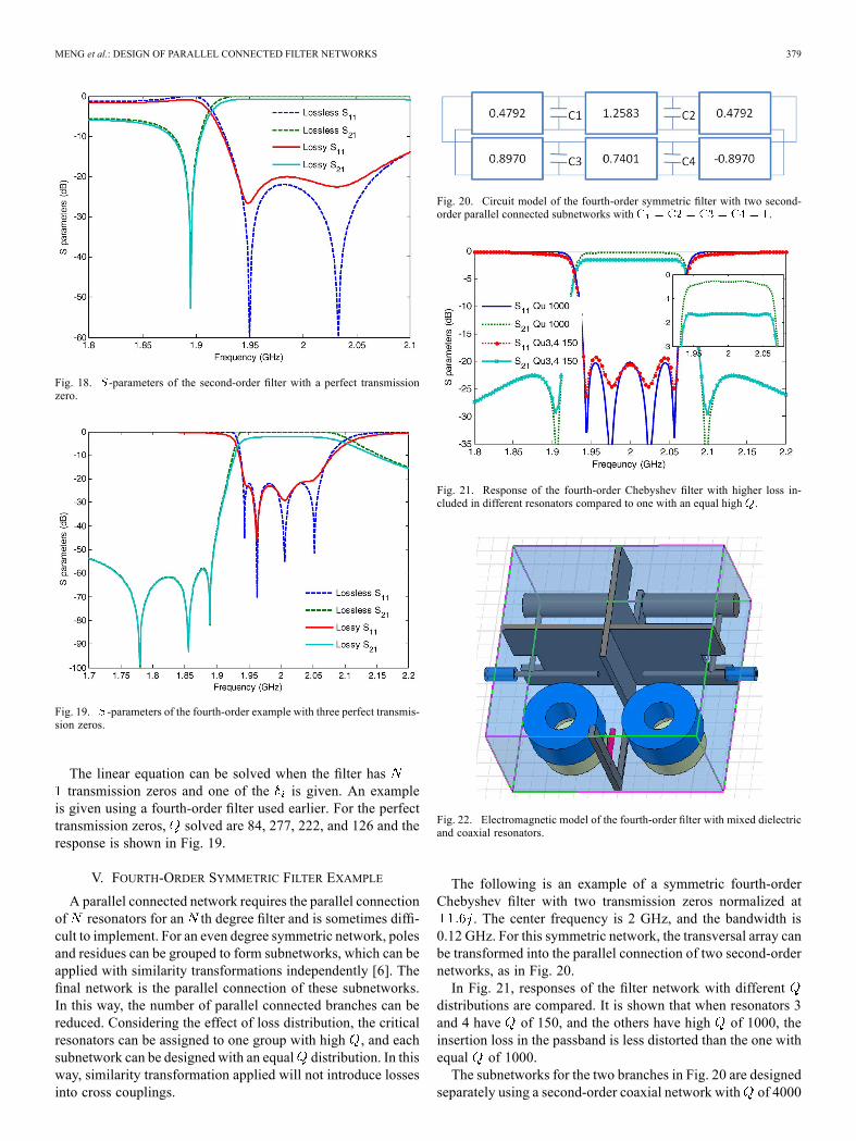
Fig. 20. Circuit model of the fourth-order symmetric filter with two second-order parallel connected subnetworks with .
Fig. 21. Response of the fourth-order Chebyshev filter with higher loss in-cluded in different resonators compared to one with an equal high .
Fig. 22. Electromagnetic model of the fourth-order filter with mixed dielectricand coaxial resonators.
The following is an example of a symmetric fourth-orderChebyshev filter with two transmission zeros normalized at
. The center frequency is 2 GHz, and the bandwidth is0.12 GHz. For this symmetric network, the transversal array canbe transformed into the parallel connection of two second-ordernetworks, as in Fig. 20.In Fig. 21, responses of the filter network with different
distributions are compared. It is shown that when resonators 3and 4 have of 150, and the others have high of 1000, theinsertion loss in the passband is less distorted than the one withequal of 1000.The subnetworks for the two branches in Fig. 20 are designed
separately using a second-order coaxial network with of 4000
380 IEEE TRANSACTIONS ON MICROWAVE THEORY AND TECHNIQUES, VOL. 61, NO. 1, JANUARY 2013
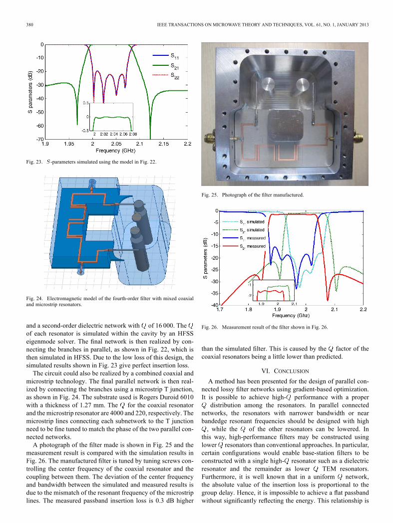
Fig. 23. -parameters simulated using the model in Fig. 22.
Fig. 24. Electromagnetic model of the fourth-order filter with mixed coaxialand microstrip resonators.
and a second-order dielectric network with of 16 000. Theof each resonator is simulated within the cavity by an HFSSeigenmode solver. The final network is then realized by con-necting the branches in parallel, as shown in Fig. 22, which isthen simulated in HFSS. Due to the low loss of this design, thesimulated results shown in Fig. 23 give perfect insertion loss.The circuit could also be realized by a combined coaxial and
microstrip technology. The final parallel network is then real-ized by connecting the branches using a microstrip T junction,as shown in Fig. 24. The substrate used is Rogers Duroid 6010with a thickness of 1.27 mm. The for the coaxial resonatorand the microstrip resonator are 4000 and 220, respectively. Themicrostrip lines connecting each subnetwork to the T junctionneed to be fine tuned to match the phase of the two parallel con-nected networks.A photograph of the filter made is shown in Fig. 25 and the
measurement result is compared with the simulation results inFig. 26. The manufactured filter is tuned by tuning screws con-trolling the center frequency of the coaxial resonator and thecoupling between them. The deviation of the center frequencyand bandwidth between the simulated and measured results isdue to the mismatch of the resonant frequency of the microstriplines. The measured passband insertion loss is 0.3 dB higher
Fig. 25. Photograph of the filter manufactured.
Fig. 26. Measurement result of the filter shown in Fig. 26.
than the simulated filter. This is caused by the factor of thecoaxial resonators being a little lower than predicted.
VI. CONCLUSION
A method has been presented for the design of parallel con-nected lossy filter networks using gradient-based optimization.It is possible to achieve high- performance with a properdistribution among the resonators. In parallel connected
networks, the resonators with narrower bandwidth or nearbandedge resonant frequencies should be designed with high, while the of the other resonators can be lowered. In
this way, high-performance filters may be constructed usinglower resonators than conventional approaches. In particular,certain configurations would enable base-station filters to beconstructed with a single high- resonator such as a dielectricresonator and the remainder as lower TEM resonators.Furthermore, it is well known that in a uniform network,the absolute value of the insertion loss is proportional to thegroup delay. Hence, it is impossible to achieve a flat passbandwithout significantly reflecting the energy. This relationship is

MENG et al.: DESIGN OF PARALLEL CONNECTED FILTER NETWORKS 381
not preserved in a nonuniform network, meaning very flatpassband may be achieved.
ACKNOWLEDGMENT
The authors would like to thank Filtronic plc, U.K., forkindly supporting author Meng’s doctoral studentship. Theauthors would also like to thank the anonymous reviewers fortheir constructive comments.
REFERENCES[1] I. C. Hunter, Theory and Design of Microwave Filters. Stevenage,
U.K.: IEE Press, 2001.[2] J. D. Rhodes and I. C. Hunter, “Synthesis of reflection-mode proto-
type networks with dissipative circuit elements,” Proc. Inst. Elect. Eng.—Microw., Antennas, Propag., vol. 144, no. 6, pp. 437–442, Dec. 1997.
[3] M. Dishal, “Design of dissipative bandpass filters producing desiredexact amplitude-frequency characteristics,” Proc. IRE, vol. 37, no. 9,pp. 1050–1069, Sep. 1949.
[4] A. E. Williams, W. G. Bush, and R. R. Bonetti, “Predistortion tech-niques for multicoupled resonator,” IEEE Trans. Microw. TheoryTechn., vol. MTT-33, no. 5, pp. 402–408, May 1985.
[5] B. S. Senior, I. C. Hunter, and J. D. Rhodes, “Synthesis of lossy filters,”in 32nd Eur. Microw. Conf., Sep. 23–26, 2002, pp. 1–4.
[6] A. C. Guyette, I. C. Hunter, and R. D. Pollard, “A new class of selectivefilters using low- components suitable for MMIC implementation,”in IEEE MTT-S Int. Microw. Symp. Dig., Jun. 6–11, 2004, vol. 3, pp.1959–1962, Vol.3.
[7] I. Hunter, A. Guyette, and R. D. Pollard, “Passive microwave receivefilter networks using low- resonators,” IEEE Microw. Mag., vol. 6,no. 3, pp. 46–53, Sep. 2005.
[8] A. C. Guyette, I. C. Hunter, and R. D. Pollard, “The design of mi-crowave bandpass filters using resonators with nonuniform ,” IEEETrans. Microw. Theory Techn., vol. 54, no. 11, pp. 3914–3922, Nov.2006.
[9] V. Miraftab and M. Yu, “Generalized lossy microwave filter couplingmatrix synthesis and design using mixed technologies,” IEEE Trans.Microw. Theory Techn., vol. 56, no. 12, pp. 3016–3027, Dec. 2008.
[10] V. Miraftab and M. Yu, “Advanced coupling matrix and admittancefunction synthesis techniques for dissipative microwave filters,” IEEETrans. Microw. Theory Techn., vol. 57, no. 10, pp. 2429–2438, Oct.2009.
[11] M. Oldoni, G. Macchiarella, G. G. Gentili, and C. Ernst, “A new ap-proach to the synthesis of microwave lossy filters,” IEEE Trans. Mi-crow. Theory Techn., vol. 58, no. 5, pp. 1222–1229, May 2010.
[12] M. Meng and I. C. Hunter, “The design of parallel connected filter net-works with non-uniform resonators,” in IEEE MTT-S Int. Microw.Symp. Dig., Jun. 17–22, 2012, pp. 1–3.
[13] R. J. Cameron, “Advanced coupling matrix synthesis techniques formicrowave filters,” IEEE Trans. Microw. Theory Techn., vol. 51, no. 1,pp. 1–10, Jan. 2003.
[14] S. Amari and M. Bekheit, “Physical interpretation and implicationsof similarity transformations in coupled resonator filter design,” IEEETrans.Microw. Theory Techn., vol. 55, no. 6, pp. 1139–1153, Jun. 2007.
[15] S. Amari, “Synthesis of cross-coupled resonator filter using an ana-lytical gradient-based optimization technique,” IEEE Trans. Microw.Theory Techn., vol. 48, no. 9, pp. 1559–1564, Sep. 2000.
Meng Meng (S’12), photograph and biography not available at time of publi-cation.
Ian C. Hunter (M’82–SM’94–F’07), photograph and biography not availableat time of publication.
John David Rhodes (M’67–SM’78–F’80–LF’09), photograph and biographynot available at time of publication.