Embed Size (px)
Citation preview
The design of micro-fluidic multi-phase reaction devices for on-flow NMR measurements 1
The design of micro-fluidic multi-phase reaction devices for on-flow NMR measurements 2
Abstract On-flow monitoring of multiphase reactions such as the Fischer-Tropsch synthesis, ethylene glycol
production from glucose, or the synthesis of methyl isobutyl ketone (MIBK) from acetone in micro-
reactors can in principle be achieved by in-situ nuclear magnetic resonance (NMR) spectroscopy. In-situ
measurements allow to gain valuable information for optimizing experimental conditions and catalyst
design. In addition, they provide insights into reaction mechanisms and potential side-product formation.
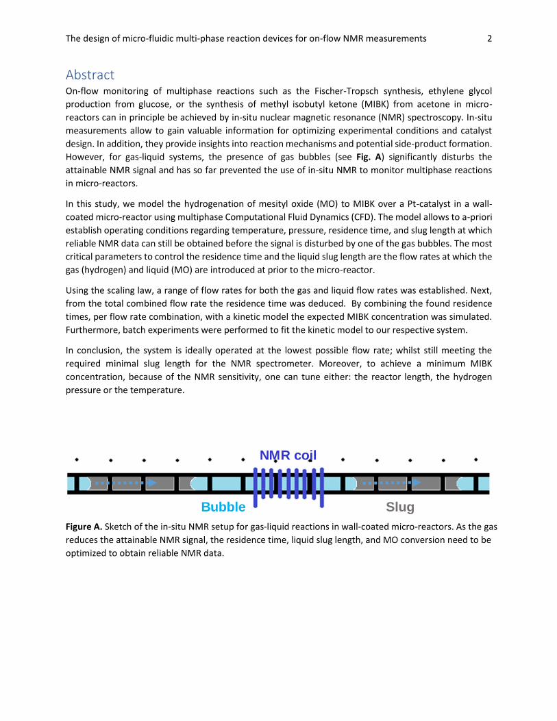
However, for gas-liquid systems, the presence of gas bubbles (see Fig. A) significantly disturbs the
attainable NMR signal and has so far prevented the use of in-situ NMR to monitor multiphase reactions
in micro-reactors.
In this study, we model the hydrogenation of mesityl oxide (MO) to MIBK over a Pt-catalyst in a wall-
coated micro-reactor using multiphase Computational Fluid Dynamics (CFD). The model allows to a-priori
establish operating conditions regarding temperature, pressure, residence time, and slug length at which
reliable NMR data can still be obtained before the signal is disturbed by one of the gas bubbles. The most
critical parameters to control the residence time and the liquid slug length are the flow rates at which the
gas (hydrogen) and liquid (MO) are introduced at prior to the micro-reactor.
Using the scaling law, a range of flow rates for both the gas and liquid flow rates was established. Next,
from the total combined flow rate the residence time was deduced. By combining the found residence
times, per flow rate combination, with a kinetic model the expected MIBK concentration was simulated.
Furthermore, batch experiments were performed to fit the kinetic model to our respective system.
In conclusion, the system is ideally operated at the lowest possible flow rate; whilst still meeting the
required minimal slug length for the NMR spectrometer. Moreover, to achieve a minimum MIBK
concentration, because of the NMR sensitivity, one can tune either: the reactor length, the hydrogen
pressure or the temperature.
Figure A. Sketch of the in-situ NMR setup for gas-liquid reactions in wall-coated micro-reactors. As the gas
reduces the attainable NMR signal, the residence time, liquid slug length, and MO conversion need to be
optimized to obtain reliable NMR data.
NMR coil
SlugBubble
The design of micro-fluidic multi-phase reaction devices for on-flow NMR measurements 3
Table of Contents Abstract ......................................................................................................................................................... 2
1.Introduction ............................................................................................................................................... 4
1.1 Background ......................................................................................................................................... 5
1.2 Aim & Approach .................................................................................................................................. 6
1.3 System Description & Limitations ....................................................................................................... 7
2. Materials & Methods ................................................................................................................................ 8
2.1 Materials ............................................................................................................................................. 8
2.1.1 Experiments ................................................................................................................................. 8
2.2 Methods .............................................................................................................................................. 9
2.2.1 Assumptions ................................................................................................................................. 9
2.2.2 Modelling ..................................................................................................................................... 9
3. Results & Discussion ............................................................................................................................... 13
3.1 Slug Lengths & Flow rates ................................................................................................................. 13
3.2 Simulated Synthesis of MIBK ............................................................................................................ 15
3.2.1 Varying Temperature and Hydrogen Pressure .......................................................................... 15
3.3 MIBK Synthesis as a function of Flow Rates ..................................................................................... 16
3.4 Case Study: limited Lreac..................................................................................................................... 17
3.5 The interactions of Lreac, Ph & T .......................................................................................................... 18
4. Perspectives & Outlook ........................................................................................................................... 19
5. Conclusion ............................................................................................................................................... 20
6. Acknowledgements ................................................................................................................................. 20
References .................................................................................................................................................. 21
Appendix A .................................................................................................................................................. 24
The design of micro-fluidic multi-phase reaction devices for on-flow NMR measurements 4
1.Introduction In the last century, the shift from industrially efficient to a greener and more sustainable processes has
become more pronounced. Especially, since the adoption of the “Pollution Prevention Act of 1990” the
paradigm of end-of-pipeline control has shifted towards pollution prevention [1]. As a result, the
terminology of: clean, benign, environmental, sustainable and green chemistry has seen a rapid rise.
Vaccaro et. al (2014), also state that the next step in turning current chemistry greener is by using
continuous micro-fluidic systems to our advantage. Micro-fluidic systems in comparison to the more
traditional batch reactors are more mobile, due to their compactness and are easily up-scalable; which
make them economically attractive [3]. In addition to the trend of miniaturization, the use of catalytic wall
coatings has also been observed, and from 2003 onwards these two developments were combined in a
field of study called Micro Structured Reactors (MSRs) [4].
However, a challenge that these continuous flow systems, such as these MSRs, face is their respective lack
of observability. Ideally with the growing popularity with the Internet of Things (=IoT) one would assume
that such issues would become less difficult [5]. On the contrary, measuring continuous systems can be
strenuous, as in-situ probes can cause interference or even disruption of the preferred flow regime [6].
Hence, a probing method is required; which does not disturb the conditions within the MSR, yet gives
information with respect to the effectiveness of the MSR. Consequently, a non-invasive probing method
of both the reactants and products would be a valuable contribution to MSRs.
Nuclear Magnetic Resonance (NMR) spectroscopy is a non-invasive probing method to measure the
concentration of both reactants and products within the reactor. NMR is based on specific nuclei
absorbing electromagnetic radiation (such as 1H and 13C isotopes) and thereby giving critical information
about the molecular environment. By analyzing the NMR spectra, one can deduce the (organic)
molecule(s) that are present in the reactor. Using such a non-invasive technique could be beneficial to
MSRs in various ways, including deepening insights into reaction mechanisms and scanning catalysts
effectiveness.
One of the problems of using NMR measurements for continuous systems is that a minimum time window
is available to acquire an adequate signal. This is because of the limited amount of time one has to
measure the products and reactants within a slug. Therefore, in on-flow NMR multiphase (gas & liquid)
measurements it is vital to have a sufficient slug-length to capture one or several NMR spectra of the
compounds within one slug. By means of Computational Fluid Dynamics (CFD), one can coherently supply
important performance parameters such as: through-put, residence time and the conversion as a function
of slug-length. A model which encompasses an application which translates inlet velocities to slug-lengths
and ultimately to these performance parameters, could thus be of value to both the industrial and
academic spheres.
By combining the fields of analytical chemistry and CFD one can further explore the potential of using on-
flow NMR measurements for the acquisition of in-situ reaction data. The benefits of this technique are
invaluable to the fields of catalyst design and reaction mapping of similar multi-phase microfluidic
systems. Therefore, this research will focus on locating the limiting factors of using on-flow NMR
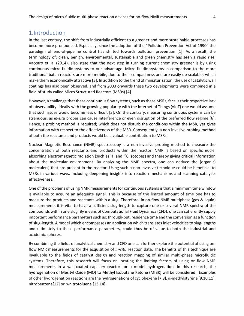
measurements in a wall-coated capillary reactor for a model hydrogenation. In this research, the
hydrogenation of Mesityl Oxide (MO) to Methyl Isobutane Ketone (MIBK) will be considered. Examples
of other hydrogenation reactions are the hydrogenations of cyclohexene [7,8], α-methylstyrene [9,10,11],
nitrobenzene[12] or p-nitrotoluene [13,14].
The design of micro-fluidic multi-phase reaction devices for on-flow NMR measurements 5
1.1 Background For MSRs, there are various reactor types which include: mixer-settler, centrifugal, columns, tubular, film,
packed bed, fluidized bed, slurry, falling film, mesh and catalytical wall reactors [4]. The different types of
MSRs are typically divided into three categories: fluid-fluid reactors, fluid-solid reactors and gas-liquid-
solid reactors. An important distinction for catalyzed reactions is whether the catalyst is present in the
same phase (homogeneous) or in a different phase (heterogeneous). More specifically, a homogeneous
catalyst is used in liquid-liquid reactors, whereas in gas-solid or gas-liquid-solid a heterogeneous catalyst
is traditionally through wall-coating or packed bed reactors. Additionally, within the previously mentioned
reactors, a multitude of different reactions have been reported: halogenations [15-18], nitrations [4],
oxidations [19], sulfonations [20] and hydrogenations [7-14]. More details on the other MSRs and
reactions can be found in the review by Kashid and Liouobov (2009).
After identifying the necessary kind of MSR, one must assess what flow regime is most beneficial.
According to Kreutzer et al. (2005), a critical parameter for capillary channel reactions is the flow regime
in which they operate. A complete list of flow patterns is beyond the scope of this research; however,
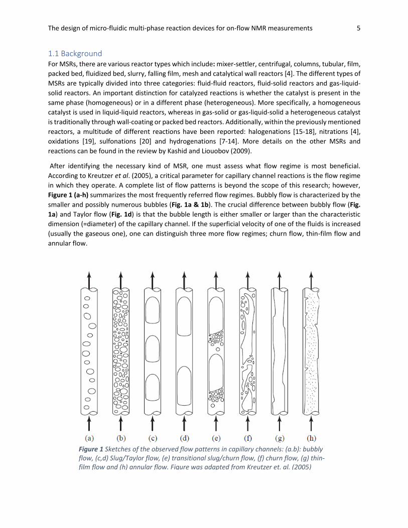
Figure 1 (a-h) summarizes the most frequently referred flow regimes. Bubbly flow is characterized by the
smaller and possibly numerous bubbles (Fig. 1a & 1b). The crucial difference between bubbly flow (Fig.
1a) and Taylor flow (Fig. 1d) is that the bubble length is either smaller or larger than the characteristic
dimension (=diameter) of the capillary channel. If the superficial velocity of one of the fluids is increased
(usually the gaseous one), one can distinguish three more flow regimes; churn flow, thin-film flow and
annular flow.
Figure 1 Sketches of the observed flow patterns in capillary channels: (a.b): bubbly flow, (c,d) Slug/Taylor flow, (e) transitional slug/churn flow, (f) churn flow, (g) thin-film flow and (h) annular flow. Figure was adapted from Kreutzer et. al. (2005)
The design of micro-fluidic multi-phase reaction devices for on-flow NMR measurements 6
As the gaseous velocity increases, the Taylor bubbles start to break-up and slowly an inner gaseous
channel can be observed. In both the thin-film and annular flow regimes, most of the center of the channel
is filled with the fastest travelling fluid. As a result, the other fluid spreads out over the remainder of the
channel forming a small thin-film close to the wall of the channel. Figure 1 h is a depiction of a channel
being filled with gas and only a very thin film and small droplets are dispersed over the capillary channel.
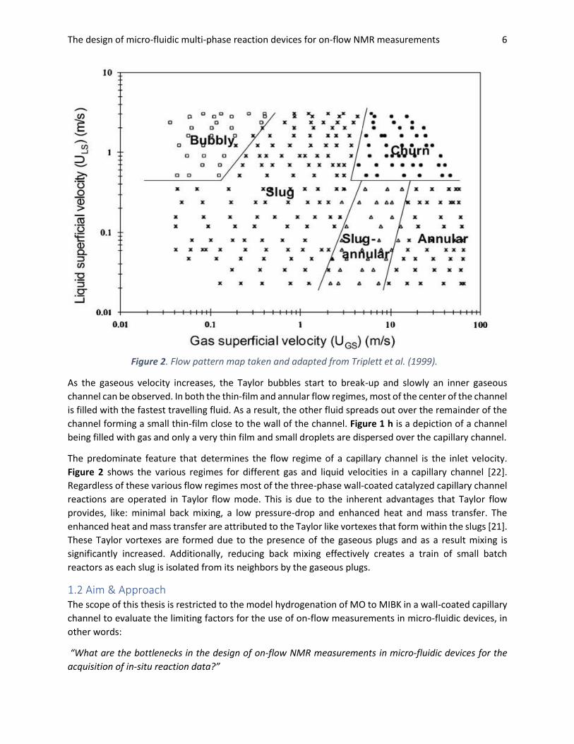
The predominate feature that determines the flow regime of a capillary channel is the inlet velocity.
Figure 2 shows the various regimes for different gas and liquid velocities in a capillary channel [22].
Regardless of these various flow regimes most of the three-phase wall-coated catalyzed capillary channel
reactions are operated in Taylor flow mode. This is due to the inherent advantages that Taylor flow
provides, like: minimal back mixing, a low pressure-drop and enhanced heat and mass transfer. The
enhanced heat and mass transfer are attributed to the Taylor like vortexes that form within the slugs [21].
These Taylor vortexes are formed due to the presence of the gaseous plugs and as a result mixing is
significantly increased. Additionally, reducing back mixing effectively creates a train of small batch
reactors as each slug is isolated from its neighbors by the gaseous plugs.
1.2 Aim & Approach The scope of this thesis is restricted to the model hydrogenation of MO to MIBK in a wall-coated capillary
channel to evaluate the limiting factors for the use of on-flow measurements in micro-fluidic devices, in
other words:
“What are the bottlenecks in the design of on-flow NMR measurements in micro-fluidic devices for the
acquisition of in-situ reaction data?”
Figure 2. Flow pattern map taken and adapted from Triplett et al. (1999).
The design of micro-fluidic multi-phase reaction devices for on-flow NMR measurements 7
By means of modelling: the slug-development (in COMSOL) and conversion of MO to MIBK (in Matlab),
one can start approaching the research questions by first answering the following sub-questions:
• “How does one translate Inlet velocities/flow rates to Slug Lengths?”
• “What are the reaction rates for the conversion from MO to MIBK?”
• “How much MIBK needs to be synthesized to observe a distinguishable signal?”
• “What design parameters (reactor length/partial pressure/inlet velocities) are required to
achieve the minimal concentration of MIBK? “
Ultimately this research aims to develop a model to aid in the experimental design of using NMR analysis
on on-flow wall-coated catalytic reactions. Once fully developed, one will be able to determine the right
inlet conditions, partial H2 pressure and reactor length a-priori, such that the slug has a sufficiently high
MIBK concentration to obtain accurate NMR data.
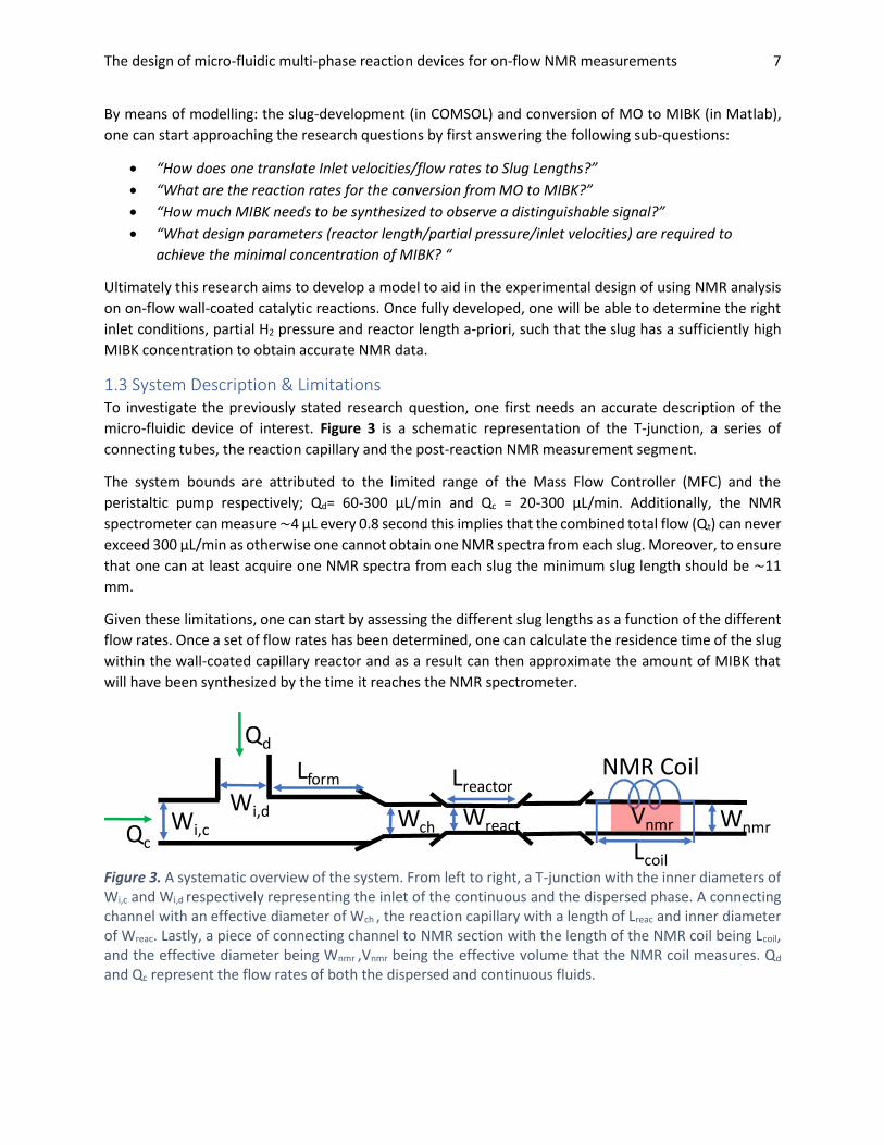
1.3 System Description & Limitations To investigate the previously stated research question, one first needs an accurate description of the
micro-fluidic device of interest. Figure 3 is a schematic representation of the T-junction, a series of
connecting tubes, the reaction capillary and the post-reaction NMR measurement segment.
The system bounds are attributed to the limited range of the Mass Flow Controller (MFC) and the
peristaltic pump respectively; Qd= 60-300 μL/min and Qc = 20-300 μL/min. Additionally, the NMR
spectrometer can measure ~4 μL every 0.8 second this implies that the combined total flow (Qt) can never
exceed 300 μL/min as otherwise one cannot obtain one NMR spectra from each slug. Moreover, to ensure
that one can at least acquire one NMR spectra from each slug the minimum slug length should be ~11
mm.
Given these limitations, one can start by assessing the different slug lengths as a function of the different
flow rates. Once a set of flow rates has been determined, one can calculate the residence time of the slug
within the wall-coated capillary reactor and as a result can then approximate the amount of MIBK that
will have been synthesized by the time it reaches the NMR spectrometer.
WreactWch
NMR Coil
Vnmr
Lcoil
Wnmr
Lreactor
Wi,c
Wi,d
Lform
Qd
Qc
Figure 3. A systematic overview of the system. From left to right, a T-junction with the inner diameters of Wi,c and Wi,d respectively representing the inlet of the continuous and the dispersed phase. A connecting channel with an effective diameter of Wch , the reaction capillary with a length of Lreac and inner diameter of Wreac. Lastly, a piece of connecting channel to NMR section with the length of the NMR coil being Lcoil, and the effective diameter being Wnmr ,Vnmr being the effective volume that the NMR coil measures. Qd and Qc represent the flow rates of both the dispersed and continuous fluids.
The design of micro-fluidic multi-phase reaction devices for on-flow NMR measurements 8
2. Materials & Methods This section will cover the materials that have been used during this study and the methods to evaluate
the previously described system. The materials section will further describe the option of reproducibility
of the experiments; whereas, the methods section will mainly focus on the derivation of the relevant
equations and justification of the made assumptions for the models.
2.1 Materials Materials used to construct the system were: 5L hydrogen 5.0 gas tank (LindeGas), 1/8” and 1/16”
Swagelok T-junctions and adaptors, BohlenderTM PTFE tubing (Sigma-Aldrich), flexible fused silica capillary
tubing (Interscience), A Mass Flow Controller (MFC) via Brooks instrument and a Miniplus evolution
peristaltic pump (Gilson). Disperal P3 nanodisperese alumna powder from Sasol and additional chemicals
were purchased from either Sigma-Aldrich or Merck.
Two analytical machines were used; namely, a gas chromatography (GC) and a 500 MHz NMR
spectrometer. The GC equipment was a Shumadzu GC-2010 equipped with ZB-FFAP column, 1 µL 1/20
split and a Flame Ionisation Detector (FID). The temperature program was set to: 2 minutes at 80oC,
increase to 100oC at a rate of 5oC/min, further increase to 240oC at a rate of 40oC/min and finally 1 minute
at 240oC. The NMR spectrometer was obtain from Bruker equipped with a home-built flow-probe and the
signals were analyzed with a TopSpin 3.5pI7 also from Bruker.
2.1.1 Experiments Two types of experiments were conducted for this study, the first being the microreactor preparation and
the second being the batch reactions.
The preparation of the microreactor was done in accordance to the work of D’Angelo et al. (2013), first
the capillaries were flushed with 1 M NaOH aqueous solution at a flow rate of 0.03 ml/min for 15 minutes.
Second the capillaries were flushed again, at the same flow rate, but with demineralized water for 15
minutes. Third, a suspension of (1 wt %) Boehemite (=32 mg Disperal P3 in 2mL MeOH) was prepared and
administered the capillaries were then sonicated to remove the air from the suspension. Fourth, the
solvent was evaporated by placing the capillaries under vacuum at room temperature for 24-72 hours.
Fifth, the boehmite was calcinated by placing them in an oven at 380oC for a span of 6 hours. Sixth, was
the impregnation with a Pt(C5H7O2)2 solution in chloroform (20 mg/mL, ± 10%wt) followed by solvent
evaporation by leaving the capillaries in a 60oC oven overnight. Seventh, the Pt calcination by again
exposing the capillaries to 350oC for 6 hours.
The batch reactions were performed in a 100mL Parr reactor 4848, an impregnation solution of 1g DP3(=
powdered y-alumina / boehmite) was (dry)-impregnated with Pt-salt (Pt(II)acetylacetonate) in chloroform
to form Pt@DP3 (powdered alumina with catalytic Pt-nanoparticles); after which 20mg Pt@DP3 powder
was added as catalyst to the batch reactor. This solution was added to 45 mL of Mesityl Oxide (MO) and
5 mL cyclohexane (CH) in the batch reactor and then put under a pressure of 20 bar H2 and kept at 50oC.
Measurements were taken at: 0,5,15,30,45,60 and 65 minutes and prior to running the GC the samples
were passed through a PTFE 0.2 µm hydrophobic filter to remove the catalyst from the samples.
The design of micro-fluidic multi-phase reaction devices for on-flow NMR measurements 9
2.2 Methods
2.2.1 Assumptions To investigate the research question, COMSOL (version 5.3) and Matlab (2017b) will be employed to
construct models which should be representative of the described system. The following assumptions will
be made for the model:
• The Pt Nano Particle (NPs) dispersion is homogeneous throughout the micro reactor;
• There is no addition or removal of the catalysts;
• The ideal gas and Henry’s law are applicable;
• The slugs are well-mixed;
• Slug volume is constant throughout the system;
• The concentration of H2 is always at the saturation concentration;
• The glass microchannel does not allow for any mass transfer from or towards the outside;
• The micro-reactor wall is completely wetted;
2.2.2 Modelling
2.2.2.1 Slug Length
Two approaches towards determining the slug length in a multi-phase system exist; the first is to model
the complete slug formation at a range of different flow rates and from there determine the respective
residence time and through-put at each flow rate. The second approach being; if the Capillary number
(Ca) < 10-2 then one can make use of the scaling law. As the bubble formation now falls within the so called
squeezing regime [24]:
𝐿𝑠
𝑊= 1 +
𝑄𝑑
𝑄𝐶
. (1)
Initially, an attempt will be made to model (in COMSOL) the complete slug-formation at various flow rates,
thereby giving insight into the transitions between flow regimes for our system. Accordingly, a plot like
that of Fig. 2 could be made, thus giving a range of flow rates, in which one can expect Taylor Flow to be
stable. Yet, due to the inexperience and the rigidness of COMSOL these CFD models were not
representative and therefore not incorporated. Alternatively, by applying the scaling law to the limits of
both the peristaltic pump and the MFC one can generate a range of ‘viable’ flow rates that meet the
minimal slug length set by the NMR equipment.
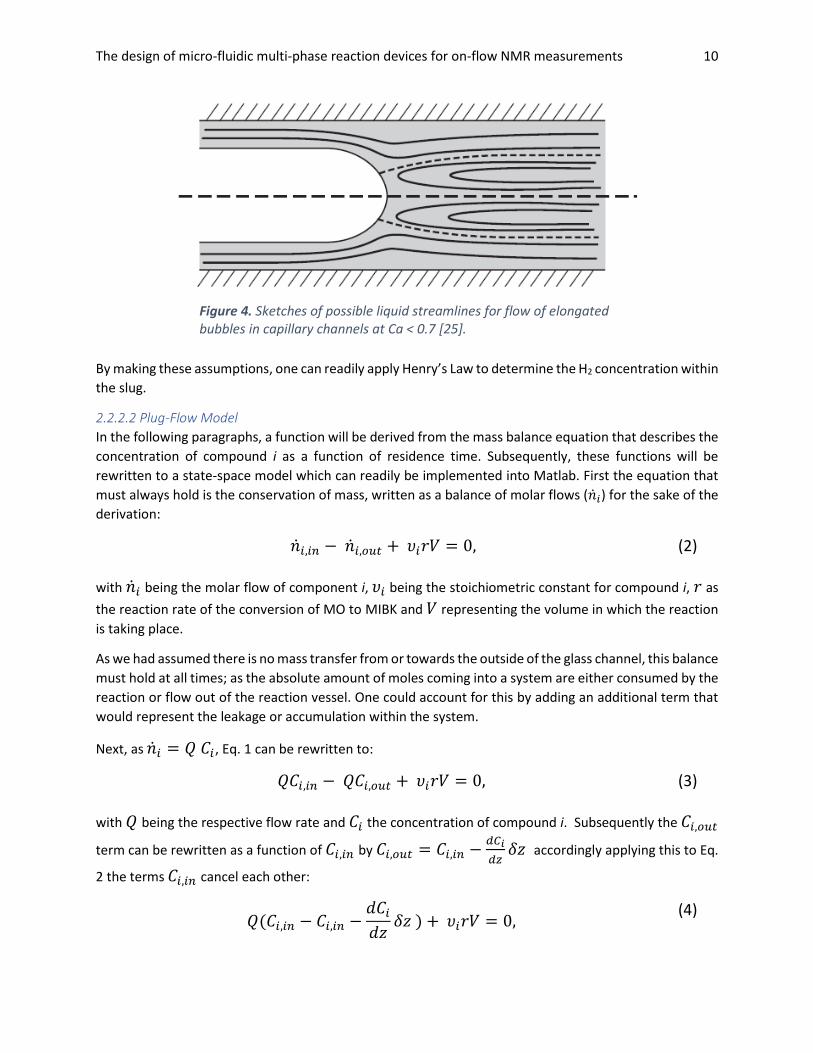
The assumption that the compounds within the slugs are well-mixed can be justified by the presence of
Taylor Vortexes [25]. Figure 4, shows the streamlines within the slug given that the Capillary Number (Ca)
< 0.7, indicating that the flow within the circles around thereby allowing for a homogeneous dispersion of
all compounds.
Moreover, the assumption that the H2 concentration is constant at the saturation pressure is validated by
two means; first, due to operating the system in Taylor flow, a train of closed-off well-mixed mini-batches,
is created and thus not developing an H2 concentration profile across the reactor. Second, it is assumed
the system is limited by the reaction rather than the diffusion. As a result, one could expect minor changes
in concentration near the interface, but throughout the slug the H2 concentration ought to be constant.
The design of micro-fluidic multi-phase reaction devices for on-flow NMR measurements 10
By making these assumptions, one can readily apply Henry’s Law to determine the H2 concentration within
the slug.
2.2.2.2 Plug-Flow Model
In the following paragraphs, a function will be derived from the mass balance equation that describes the
concentration of compound i as a function of residence time. Subsequently, these functions will be
rewritten to a state-space model which can readily be implemented into Matlab. First the equation that
must always hold is the conservation of mass, written as a balance of molar flows (�̇�𝑖) for the sake of the
derivation:
�̇�𝑖,𝑖𝑛 − �̇�𝑖,𝑜𝑢𝑡 + 𝜐𝑖𝑟𝑉 = 0, (2)
with �̇�𝑖 being the molar flow of component i, 𝜐𝑖 being the stoichiometric constant for compound i, 𝑟 as
the reaction rate of the conversion of MO to MIBK and 𝑉 representing the volume in which the reaction
is taking place.
As we had assumed there is no mass transfer from or towards the outside of the glass channel, this balance
must hold at all times; as the absolute amount of moles coming into a system are either consumed by the
reaction or flow out of the reaction vessel. One could account for this by adding an additional term that
would represent the leakage or accumulation within the system.
Next, as �̇�𝑖 = 𝑄 𝐶𝑖 , Eq. 1 can be rewritten to:
𝑄𝐶𝑖,𝑖𝑛 − 𝑄𝐶𝑖,𝑜𝑢𝑡 + 𝜐𝑖𝑟𝑉 = 0, (3)
with 𝑄 being the respective flow rate and 𝐶𝑖 the concentration of compound i. Subsequently the 𝐶𝑖,𝑜𝑢𝑡
term can be rewritten as a function of 𝐶𝑖,𝑖𝑛 by 𝐶𝑖,𝑜𝑢𝑡 = 𝐶𝑖,𝑖𝑛 −𝑑𝐶𝑖
𝑑𝑧𝛿𝑧 accordingly applying this to Eq.
2 the terms 𝐶𝑖,𝑖𝑛 cancel each other:
𝑄(𝐶𝑖,𝑖𝑛 − 𝐶𝑖,𝑖𝑛 −𝑑𝐶𝑖
𝑑𝑧𝛿𝑧 ) + 𝜐𝑖𝑟𝑉 = 0,
(4)
Figure 4. Sketches of possible liquid streamlines for flow of elongated bubbles in capillary channels at Ca < 0.7 [25].
The design of micro-fluidic multi-phase reaction devices for on-flow NMR measurements 11
−𝑄𝑑𝐶𝑖
𝑑𝑧𝛿𝑧 + 𝜐𝑖𝑟𝑉 = 0.
(5)
Following the substitution of 𝐶𝑖,𝑖𝑛 𝑄 can be rewritten as 𝑄 = 𝜈𝐴 (= superficial velocity multiplied by the
effective area) and 𝑉 as 𝑉 = 𝐴𝛿𝑧:
−𝜈𝐴𝑑𝐶𝑖
𝑑𝑧𝛿𝑧 + 𝜐𝑖𝑟 𝐴𝛿𝑧 = 0,
(6)
It then follows that both 𝐴 and 𝛿𝑧 are present in both terms and therefore cancel out, further
simplifying Eq. 5 to:
𝑑𝐶𝑖
𝑑𝑧 =
1
𝜈 𝜐𝑖𝑟.
(7)
Finally, by integrating Eq. 6 over the length of the reactor 𝐿 the concentration of a compound is given
by:
𝐶𝑖 =𝐿
𝜈 𝜐𝑖𝑟 = 𝜏 𝜐𝑖𝑟 ,
(8)
in which 𝜏 represents the residence time defined as: 𝜏 =𝐿
𝜈 .
2.2.2.3 Conversion of MO to MIBK
Different models have been fitted for the reaction of MO to MIBK [26-28], the fitted model of O’Keefe et
al. (2005) was chosen as a first point of reference:
𝑟 =𝜅1𝐶𝑀𝑂𝑃𝐻
(1 + 𝜅2𝐶𝑀𝑂2)4
, (9)
with 𝜅1 and 𝜅2 being the respective fitting parameters for this model and 𝑃𝐻 representing the hydrogen
partial pressure. Eq.9 is the fitted model by O’Keefe et al. (2005) which is based on a Langmuir-
Hinshelwood model but reduced to a two-parameter model for the comparison to the other models.
This literature based model allows one to already roughly approximate the flow rates and slug-lengths of
interest. Next, this model could be fitted to the acquired batch data for further analysis. Having covered
both the derivation and the two different cases of the reaction rates; the literature based and the fitted
models, one can now readily represent the system in a state-space format:
𝑥 = [𝐶𝑀𝐼𝐵𝐾
𝐶𝑀𝑂] , 𝑝 = [
𝜅1
𝜅2
𝑝𝑝] , 𝑥0 = [
𝐶𝑖,𝑀𝐼𝐵𝐾
𝐶𝑖,𝑀𝑂] = [
0𝜌𝑀𝑂/𝑀𝑤,𝑀𝑂
],
The design of micro-fluidic multi-phase reaction devices for on-flow NMR measurements 12
𝑑𝑥
𝑑𝑡= [
𝑟
−𝑑𝑥1
𝑑𝑡] = [
𝑝1𝑥2𝑝3
(1 + 𝑝2𝑥22)4
−𝑑𝑥1
𝑑𝑡
].
(10)
As to the assumptions with respect to the catalyst and its dispersion, accounting for a not homogeneously
dispersed and fluctuating amount of catalyst, would make the model needlessly complex. Especially since
an approximation of the required flow-rates and slug-lengths such that enough MIBK is synthesized would
be sufficient for this research.
The design of micro-fluidic multi-phase reaction devices for on-flow NMR measurements 13
3. Results & Discussion In the following paragraphs, the results of the two models; the literature and experimentally fitted models
will be presented. In the first section an overview of the different slug-lengths (Ls) as a function of flow
rates will be sketched. After determining the required flow rates, to ensure a sufficient slug length, the
residence time can be deduced and thus the synthesized MIBK concentration can be simulated. In the last
section the deduced residence times will be linked to the predicted MIBK concentration. This results in an
overview of the approximate MIBK concentrations one can expect when operating the described system
at various flow rates.
3.1 Slug Lengths & Flow rates As defined by Eq. 1, if the Capillary number (Ca) is below 10-2, the slug formation falls within the so-called
squeezing regime [24]. The Ca of this system is 4.4E-8 is well below the defined threshold, which means
the scaling law (Eq.1) can be applied to predict the various slug lengths.
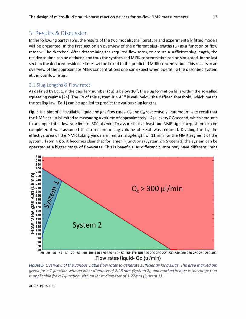
Fig. 5 is a plot of all available liquid and gas flow rates, Qc and Qd respectively. Paramount is to recall that
the NMR set-up is limited to measuring a volume of approximately ~4 μL every 0.8 second, which amounts
to an upper total flow rate limit of 300 μL/min. To assure that at least one NMR signal acquisition can be
completed it was assumed that a minimum slug volume of ~8μL was required. Dividing this by the
effective area of the NMR tubing yields a minimum slug-length of 11 mm for the NMR segment of the
system. From Fig 5. it becomes clear that for larger T-junctions (System 2 > System 1) the system can be
operated at a bigger range of flow-rates. This is beneficial as different pumps may have different limits
and step-sizes.
System 2
Qt > 300 μl/min
Figure 5. Overview of the various viable flow rates to generate sufficiently long slugs. The area marked om green for a T-junction with an inner diameter of 2.28 mm (System 2), and marked in blue is the range that is applicable for a T-junction with an inner diameter of 1.27mm (System 1).
The design of micro-fluidic multi-phase reaction devices for on-flow NMR measurements 14
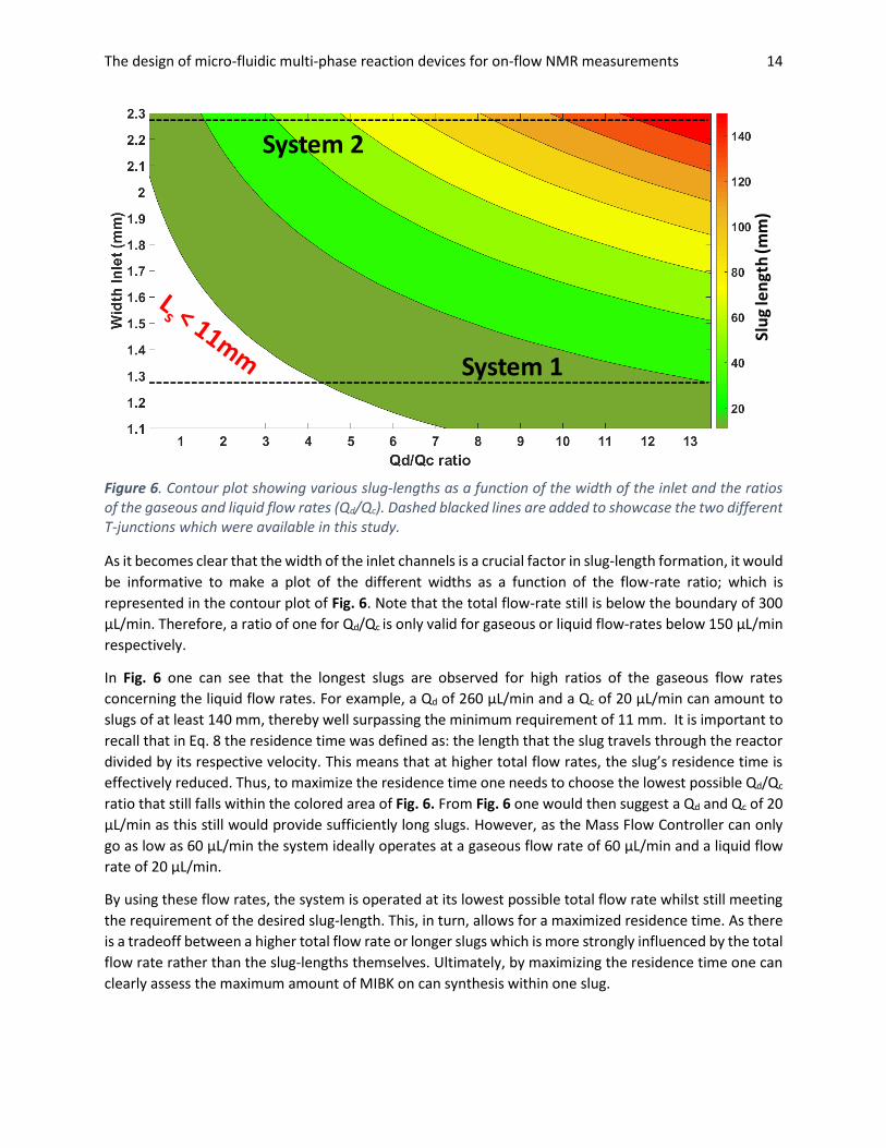
As it becomes clear that the width of the inlet channels is a crucial factor in slug-length formation, it would
be informative to make a plot of the different widths as a function of the flow-rate ratio; which is
represented in the contour plot of Fig. 6. Note that the total flow-rate still is below the boundary of 300
μL/min. Therefore, a ratio of one for Qd/Qc is only valid for gaseous or liquid flow-rates below 150 μL/min
respectively.
In Fig. 6 one can see that the longest slugs are observed for high ratios of the gaseous flow rates
concerning the liquid flow rates. For example, a Qd of 260 μL/min and a Qc of 20 μL/min can amount to
slugs of at least 140 mm, thereby well surpassing the minimum requirement of 11 mm. It is important to
recall that in Eq. 8 the residence time was defined as: the length that the slug travels through the reactor
divided by its respective velocity. This means that at higher total flow rates, the slug’s residence time is
effectively reduced. Thus, to maximize the residence time one needs to choose the lowest possible Qd/Qc
ratio that still falls within the colored area of Fig. 6. From Fig. 6 one would then suggest a Qd and Qc of 20
μL/min as this still would provide sufficiently long slugs. However, as the Mass Flow Controller can only
go as low as 60 μL/min the system ideally operates at a gaseous flow rate of 60 μL/min and a liquid flow
rate of 20 μL/min.
By using these flow rates, the system is operated at its lowest possible total flow rate whilst still meeting
the requirement of the desired slug-length. This, in turn, allows for a maximized residence time. As there
is a tradeoff between a higher total flow rate or longer slugs which is more strongly influenced by the total
flow rate rather than the slug-lengths themselves. Ultimately, by maximizing the residence time one can
clearly assess the maximum amount of MIBK on can synthesis within one slug.
System 1
System 2
Slu
g le
ngt
h (m
m)
Figure 6. Contour plot showing various slug-lengths as a function of the width of the inlet and the ratios of the gaseous and liquid flow rates (Qd/Qc). Dashed blacked lines are added to showcase the two different T-junctions which were available in this study.
The design of micro-fluidic multi-phase reaction devices for on-flow NMR measurements 15
3.2 Simulated Synthesis of MIBK After having gained some insight into the slug-length and the total flow rate, it is important to simulate
the MIBK concentration by using the model described in Eq. 10. As a swift reminder, even though the
literature model and the simulated model are of the same form (Eq. 10) the fitting parameters 𝜅1 and 𝜅2 are either taken from O’Keefe et al. (2005) or fitted to the described batch experiment.
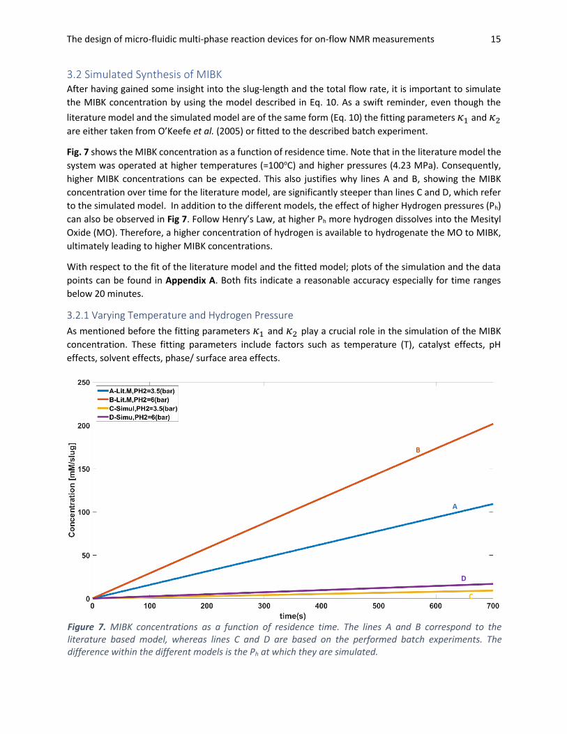
Fig. 7 shows the MIBK concentration as a function of residence time. Note that in the literature model the
system was operated at higher temperatures (=100oC) and higher pressures (4.23 MPa). Consequently,
higher MIBK concentrations can be expected. This also justifies why lines A and B, showing the MIBK
concentration over time for the literature model, are significantly steeper than lines C and D, which refer
to the simulated model. In addition to the different models, the effect of higher Hydrogen pressures (Ph)
can also be observed in Fig 7. Follow Henry’s Law, at higher Ph more hydrogen dissolves into the Mesityl
Oxide (MO). Therefore, a higher concentration of hydrogen is available to hydrogenate the MO to MIBK,
ultimately leading to higher MIBK concentrations.
With respect to the fit of the literature model and the fitted model; plots of the simulation and the data
points can be found in Appendix A. Both fits indicate a reasonable accuracy especially for time ranges
below 20 minutes.
3.2.1 Varying Temperature and Hydrogen Pressure
As mentioned before the fitting parameters 𝜅1 and 𝜅2 play a crucial role in the simulation of the MIBK
concentration. These fitting parameters include factors such as temperature (T), catalyst effects, pH
effects, solvent effects, phase/ surface area effects.
A
C
B
D
Figure 7. MIBK concentrations as a function of residence time. The lines A and B correspond to the literature based model, whereas lines C and D are based on the performed batch experiments. The difference within the different models is the Ph at which they are simulated.
The design of micro-fluidic multi-phase reaction devices for on-flow NMR measurements 16
[MIB
K]
(mM
/slu
g)
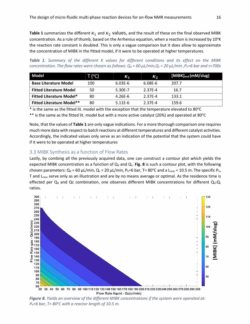
Figure 8. Yields an overview of the different MIBK concentrations if the system were operated at: Ph=6 bar, T= 80oC with a reactor length of 10.5 m.
Table 1 summarizes the different 𝜅1 and 𝜅2 values, and the result of these on the final observed MIBK
concentration. As a rule of thumb, based on the Arrhenius equation, when a reaction is increased by 10oK
the reaction rate constant is doubled. This is only a vague comparison but it does allow to approximate
the concentration of MIBK in the fitted model, if it were to be operated at higher temperatures.
Table 1. Summary of the different K values for different conditions and its effect on the MIBK concentration. The flow rates were chosen as follows: Qd = 60 μL/min,Qc = 20 μL/min ,Ph=6 bar and τ=700s
Model T (oC) 𝜿𝟏 𝜿𝟐 [MIBK]end (mM/slug)
Base Literature Model 100 6.03E-6 6.08E-6 207.7
Fitted Literature Model 50 5.30E-7 2.37E-4 16.7
Fitted Literature Model* 80 4.26E-6 2.37E-4 133.1
Fitted Literature Model** 80 5.11E-6 2.37E-4 159.6
* is the same as the fitted lit. model with the exception that the temperature elevated to 80oC
** is the same as the fitted lit. model but with a more active catalyst (20%) and operated at 80oC
Note, that the values of Table 1 are only vague indications. For a more thorough comparison one requires
much more data with respect to batch reactions at different temperatures and different catalyst activities.
Accordingly, the indicated values only serve as an indication of the potential that the system could have
if it were to be operated at higher temperatures
3.3 MIBK Synthesis as a function of Flow Rates Lastly, by combing all the previously acquired data, one can construct a contour plot which yields the
expected MIBK concentration as a function of Qd and Qc. Fig. 8 is such a contour plot, with the following
chosen parameters: Qd = 60 μL/min, Qc = 20 μL/min, Ph=6 bar, T= 80oC and a Lreac = 10.5 m. The specific Ph,
T and Lreac serve only as an illustration and are by no means average or optimal. As the residence time is
effected per Qd and Qc combination, one observes different MIBK concentrations for different Qd:Qc
ratios.
The design of micro-fluidic multi-phase reaction devices for on-flow NMR measurements 17
3.4 Case Study: limited Lreac In this section, a case in which the reactor length is the limiting factor of our system. Reactor length can
be a limiting factor either due to material or time constraints, and for this case Lreac = 4 m. Additionally,
another requirement, with respect to the NMR sensitivity, at least 100 mM of MIBK needs to be
synthesized to observe distinguishable peaks within the NMR acquired spectra.
Given these constraints, the assessment of this case takes the same approach as presented in the results
section. First, a choice with respect to gas and liquid flow rates must be made. Second, the residence time
of one slug through four meters of reactor can be deduced. Third, the simulated model is evaluated for
the respective residence time at various temperatures and hydrogen pressures.
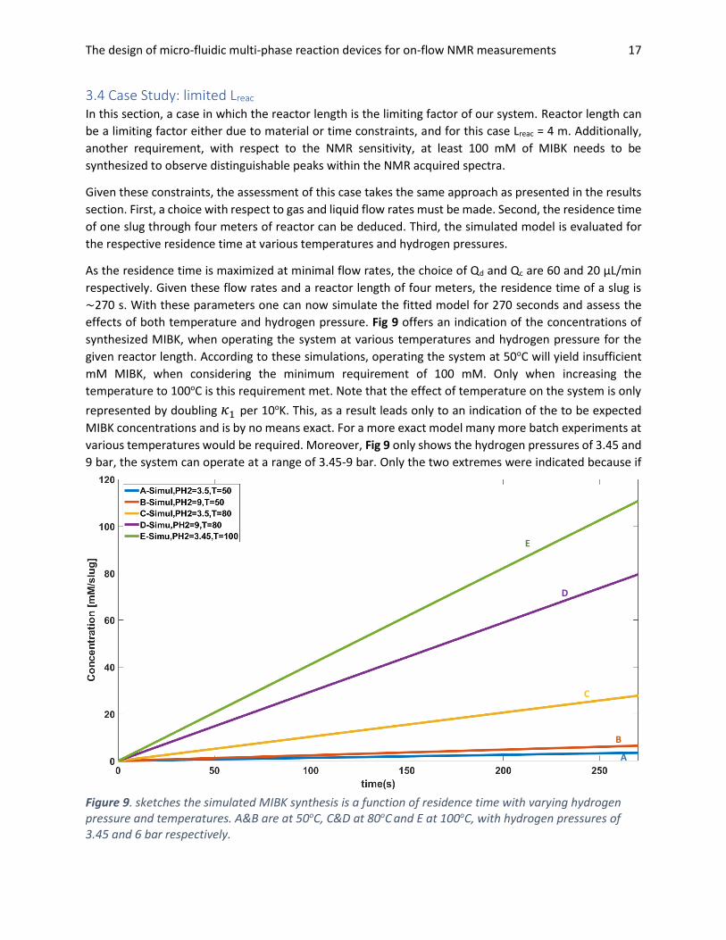
As the residence time is maximized at minimal flow rates, the choice of Qd and Qc are 60 and 20 μL/min
respectively. Given these flow rates and a reactor length of four meters, the residence time of a slug is
~270 s. With these parameters one can now simulate the fitted model for 270 seconds and assess the
effects of both temperature and hydrogen pressure. Fig 9 offers an indication of the concentrations of
synthesized MIBK, when operating the system at various temperatures and hydrogen pressure for the
given reactor length. According to these simulations, operating the system at 50oC will yield insufficient
mM MIBK, when considering the minimum requirement of 100 mM. Only when increasing the
temperature to 100oC is this requirement met. Note that the effect of temperature on the system is only
represented by doubling 𝜅1 per 10oK. This, as a result leads only to an indication of the to be expected
MIBK concentrations and is by no means exact. For a more exact model many more batch experiments at
various temperatures would be required. Moreover, Fig 9 only shows the hydrogen pressures of 3.45 and
9 bar, the system can operate at a range of 3.45-9 bar. Only the two extremes were indicated because if
Figure 9. sketches the simulated MIBK synthesis is a function of residence time with varying hydrogen pressure and temperatures. A&B are at 50oC, C&D at 80oC and E at 100oC, with hydrogen pressures of 3.45 and 6 bar respectively.
A
C
B
D
E
The design of micro-fluidic multi-phase reaction devices for on-flow NMR measurements 18
at the highest hydrogen pressure the requirement is not met, neither will it be met at lower hydrogen
pressures.
All in all, to synthesize 100 mM MIBK per slug, one should carefully study the structural stability of the
systems connections and tubing to then operate the system within a safe but maximum margin of both
hydrogen pressure and temperature. Although from first indications it seems that operating the system
below 100oC, with a reactor length of four meter would not recommended.
3.5 The interactions of Lreac, Ph & T As is clear from the case study (Section 3.4) one needs to carefully weigh the factors: reactor-length (Lreac),
temperature (T) and hydrogen pressure (Ph). Fig 8 shows that; for a maximum MIBK concentration one
will need to operate the system at the lowest possible total flow rates while still meeting the required slug
length as displayed in Fig 6.
As a result, the only way to further increase the residence time is by lengthening the reactor segment of
the system. As the total flow rate remained the same the slug is effectively exposed longer to a catalytic
wall coated capillary and thus can synthesis more MIBK. However, there are two key problems that arise
with increasing the reactor length: an increase in pressure drop over the reactor and the need to prepare
more capillaries. The additional lab work aside, a higher pressure-drop over the system could mean that
at some point the slugs will not be able to proceed further in the channel. To minimize the pressure-drop
over the channel, it would therefore be recommended to flush the complete system with a pure MO
solution prior to incorporating the hydrogen bubbles. This will ensure that all walls will be wetted prior to
the introduction of the bubbles, thus ensuring better stability of the system.
An alternative to increasing the Lreac is to operate at higher hydrogen pressures. Due to Henry’s Law, a
higher dissolved hydrogen concentration will be present in the slugs and consequently allow for more MO
to hydrogenate to MIBK within the same residence time. Additionally, by introducing the bubbles at a
higher pressure one also indirectly tackles any problems the pressure drop may cause, as the system is
now operating at higher pressures. A potential downside in using a higher Ph is that one must be mindful
of the structural stability of both the connections and the tubing of the system. By increasing the overall
pressure, the system is more prone to either leakages or complete dislodging of the tubing within the
connectors.
Finally, one can always further increase the temperature at which the reaction takes place. Microfluidic
devices due to their miniature nature have excellent heat transfer rates [21]. Even if it is assumed that the
expanding and shrinking of the gaseous bubbles due to the temperature differences is neglectable, one
should ensure that the system is not permeable to the heating medium that the system is exposed to.
This once more raises the issue of the structural stability of the connections and tubing in between the
different sections of the system.
The design of micro-fluidic multi-phase reaction devices for on-flow NMR measurements 19
4. Perspectives & Outlook This research could be continued in two ways: i) by improving the model and/or ii) by studying the
acquired NMR data and its further implementation. First, the points on which the presented model could
be improved further on, will be given. Second, a few suggestions will be presented with respect to what
the following steps could be to further the implementation of NMR in on-flow microfluidic devices.
For the slug development within this research, due to our Ca being sufficiently low, one could make use
of the scaling law (Eq.1). Yet, for a more general design of micro-fluidic multi-phase reaction devices for
on-flow NMR measurements, the model would benefit from a more detailed description of slug-
development outside of the squeezing regime. A considerable amount of work on this has already been
performed [29-31]. In the work of Nekouei (2017), a summary is provided with the various numerical
simulation studies that have been performed on microfluidic T-junction devices.
Regarding the conversion of MO to MIBK; both the external and internal mass transfer rates were
neglected, as the system was assumed to be reaction limited. Prior to determining whether this system is
diffusion or reaction limited a more detailed description of the mass transfer processes is required. In the
work of Kreutzer et al. (2001), provides an elaborate overview of the different mass transfer processes is
provided.
Moreover, to more accurately describe the kinetics of the hydrogenation of mesityl oxide to mesityl
isobutane ketone more data is required. As mentioned in the Materials & Methods (Section 2.2.2.3), in
the work of O’Keefe et al. (2005) an overview is given regarding different models for the synthesis of MIBK.
Nevertheless, the systems presented are not an exact fit for the system of this study. Thus, performing
more batch experiments at different temperatures (and different catalysts) will lead to better insight into
the exact kinetics of this hydrogenation within our system. Thereby, enabling the creation of a model that
fits the data better.
A valuable future avenue is the combination of a Computation Fluid Dynamics (CFD) model with a kinetic
model of a respective reaction. Such a combination of both CFD and kinetic models could be achieved in
multiphysics encompassing programs such as COMSOL or OpenFoam [33]. Given such a model, drawing
comparisons between longer and shorter slug and comment on their respective conversions could be
made. Furthermore, condensing the information from for example Fig. 6 and Fig. 8 into on plot would
make the topic more accessible to those new to the subject.
Next, to further improve the model, there are still at least two steps in achieving actual on-flow NMR
measurements on micro-fluidic multi-phase reactions. The first step would be to measure a section of the
reaction capillary with NMR. This could be achieved by applying the same catalytic coating to a part of the
NMR system and then stopping the flow-rate to observe any change in the slug’s composition. Even
though this is also not on-flow NMR; if one can demonstrate observable differences in a stop-flow system.
Then the second and only remaining issue would be to move onto on-flow measurements to measure a
sufficiently large volume. This last issue may prove difficult when considering that for the system of this
research Wreac << WNMR, meaning that one would need to measure a longer section of the reactor to
measure the same volume. Ultimately, this leads to the trade-off between measuring a sufficiently large
volume or attaining a more sensitive NMR spectrometer.
The design of micro-fluidic multi-phase reaction devices for on-flow NMR measurements 20
5. Conclusion For the design of on-flow NMR measurements in a multi-phase microfluidic reaction device, the
conversion of Mesityl Oxide (MO) to Methyl Isobutane Ketone (MIBK) was modelled. By combining; the
scaling law, a plug-flow model and a Langmuir-Hinshelwood based reaction model an overview could be
made to circumvent the interfering hydrogen bubbles for NMR acquisition. From the scaling law and plug-
flow model it became apparent that for maximum residence times, in our system, one should use the
lowest possible flow rates of the Mass Flow Controller (MFC) and the peristaltic pump. In this study that
meant a gaseous flow rate (Qd) of 60 µL/min and a liquid flow rate (Qc) of 20 µL/min. With these flow rates
a sufficient long slug was formed in which one could at least conduct one NMR acquisition. To acquire the
desired amount of mM/slug, one can change the following parameters: the reactor length (Lreac), the
hydrogen pressure (Ph) and the temperature (T). By operating the system at a higher Ph or T one can
synthesis more MIBK whilst keeping the residence time the same. Whereas, by increasing Lreac one directly
increases the residence time thus allowing for more MIBK to form. Alternatively, with a more sensitive
NMR spectrometer one could also quantify MIBK at lower concentrations. All in all, depending on the
available materials and wishes one is now posed with a design choice of playing with either Lreac, Ph or T
and Qd and Qc if the dimensions of the inlet are not set.
6. Acknowledgements The author would like to thank: Gerben Wiedra for all his time and patience and advice he has given over
the course of this Thesis, Lars Kiewidt for always being available and offering a listening ear or a critical
analysis and Ton van Boxtel and Harry Bitter for the opportunity to work on this project. Lastly, I would
like to thank all my peers for the many reviews in the thesis rings and the overall great time at BCT.
The design of micro-fluidic multi-phase reaction devices for on-flow NMR measurements 21
References [1] Linthorst, J. A. "An overview: origins and development of green chemistry." Foundations of chemistry
12, no. 1 (2010): 55-68.
[2] Vaccaro, Luigi, Daniela Lanari, Assunta Marrocchi, and Giacomo Strappaveccia. "Flow approaches
towards sustainability." Green Chemistry 16, no. 8 (2014): 3680-3704.
[3] Roberge, Dominique M., Bertin Zimmermann, Fabio Rainone, Michael Gottsponer, Markus Eyholzer,
and Norbert Kockmann. "Microreactor technology and continuous processes in the fine chemical and
pharmaceutical industry: is the revolution underway?." Organic Process Research & Development 12, no.
5 (2008): 905-910.
[4] Kashid, Madhvanand N., and Lioubov Kiwi-Minsker. "Microstructured reactors for multiphase
reactions: state of the art." Industrial & Engineering Chemistry Research 48, no. 14 (2009): 6465-6485.
[5] Zhang, Daqiang, Huansheng Ning, Kevin S. Xu, Feiyu Lin and Laurence T. Yang. “Internet of Things.” J.
UCS 18 (2012): 1069-1071.
[6] Ulpts, Jürgen, Wolfgang Dreher, Lars Kiewidt, Miriam Schubert, and Jorg Thöming. "In situ analysis of
gas phase reaction processes within monolithic catalyst supports by applying NMR imaging
methods." Catalysis Today 273 (2016): 91-98.
[7] Losey, Matthew W., Martin A. Schmidt, and Klavs F. Jensen. "Microfabricated multiphase packed-bed
reactors: characterization of mass transfer and reactions." Industrial & engineering chemistry
research 40, no. 12 (2001): 2555-2562.
[8] Losey, Matthew W., Rebecca J. Jackman, Samara L. Firebaugh, Martin A. Schmidt, and Klavs F.
Jensen. "Design and fabrication of microfluidic devices for multiphase mixing and reaction." Journal of
Microelectromechanical Systems 11, no. 6 (2002): 709-717.
[9] Hessel, Volker, Panagiota Angeli, Asterios Gavriilidis, and Holger Löwe. "Gas− liquid and gas− liquid−
solid microstructured reactors: contacting principles and applications." Industrial & engineering
chemistry research 44, no. 25 (2005): 9750-9769.
[10] Abdallah, Radwan, Valérie Meille, John Shaw, David Wenn, and Claude de Bellefon. "Gas–liquid and
gas–liquid–solid catalysis in a mesh microreactor." Chemical Communications4 (2004): 372-373.
[11] Losey, M. W., M. A. Schmidt, and K. F. Jensen. "A micro packed-bed reactor for chemical synthesis."
In Microreaction technology: Industrial prospects, pp. 277-286. Springer, Berlin, Heidelberg, 2000.
[12] Yeong, Kay Kin, Asterios Gavriilidis, Ralf Zapf, and Volker Hessel. "Catalyst preparation and
deactivation issues for nitrobenzene hydrogenation in a microstructured falling film reactor." Catalysis
Today 81, no. 4 (2003): 641-651.
[13] Födisch, Ringo, Dieter Hönicke, Yugong Xu, and Bernd Platzer. "Liquid phase hydrogenation of p-
nitrotoluene in microchannel reactors." In Microreaction Technology, pp. 470-478. Springer, Berlin,
Heidelberg, 2001.
[14] Reschetilowski, W., and D. Honicke. "Heterogeneously catalyzed liquidphase hydrogenation of
nitro-aromatics using microchannel reactors." DGMK Tagungsber 9903 (1999): 231-238.
[15] Jähnisch, K., M. Baerns, V. Hessel, W. Ehrfeld, V. Haverkamp, H. Löwe, Ch Wille, and A. Guber.
"Direct fluorination of toluene using elemental fluorine in gas/liquid microreactors." Journal of Fluorine
Chemistry 105, no. 1 (2000): 117-128.
The design of micro-fluidic multi-phase reaction devices for on-flow NMR measurements 22
[16] de Mas, Nuria, Rebecca J. Jackman, Martin A. Schmidt, and Klavs F. Jensen. "Microchemical Systems
for Direct Fluorination of." In Microreaction Technology: IMRET 5: Proceedings of the Fifth International
Conference on Microreaction Technology, p. 60. Springer Science & Business Media, 2012.
[17] Chambers, Richard D., Darren Holling, Robert CH Spink, and Graham Sandford. "Elemental fluorine
Part 13. Gas–liquid thin film microreactors for selective direct fluorination." Lab on a Chip 1, no. 2
(2001): 132-137.
[18] Wehle, D., M. Dejmek, J. Rosenthal, H. Ernst, D. Kampmann, S. Trautschold, and R. Pechatschek.
"Chlorinated organic compounds production." Clariant GmbH, WO200210094-A.
[19] Chambers, Richard D., Darren Holling, Anthony J. Rees, and Graham Sandford. "Microreactors for
oxidations using fluorine." Journal of fluorine chemistry 119, no. 1 (2003): 81-82. [20]
[20] Müller, A., V. Cominos, V. Hessel, B. Horn, J. Schürer, A. Ziogas, K. Jähnisch et al. "Fluidic bus system
for chemical process engineering in the laboratory and for small-scale production." Chemical
Engineering Journal 107, no. 1-3 (2005): 205-214.
[21] Kreutzer, Michiel T., Freek Kapteijn, Jacob A. Moulijn, and Johan J. Heiszwolf. "Multiphase monolith
reactors: chemical reaction engineering of segmented flow in microchannels." Chemical Engineering
Science 60, no. 22 (2005): 5895-5916.
[22] Triplett, K. A., S. M. Ghiaasiaan, S. I. Abdel-Khalik, and D. L. Sadowski. "Gas–liquid two-phase flow in
microchannels Part I: two-phase flow patterns." International Journal of Multiphase Flow 25, no. 3
(1999): 377-394.
[23] Neira D’Angelo, M. F., J. C. Schouten, J. van der Schaaf, and T. A. Nijhuis. "Three-phase reactor
model for the aqueous phase reforming of ethylene glycol." Industrial & Engineering Chemistry
Research 53, no. 36 (2014): 13892-13902.
[24] Hessel, Volker, Jaap C. Schouten, and Albert Renken, eds. Micro process engineering: a
comprehensive handbook. Vol. 1. John Wiley & Sons, 2009.
[25] Taylor, G. I. "Deposition of a viscous fluid on the wall of a tube." Journal of Fluid Mechanics 10, no. 2
(1961): 161-165.
[26] O’Keefe, W. K., M. Jiang, F. T. T. Ng, and G. L. Rempel. "Liquid phase kinetics for the selective
hydrogenation of mesityl oxide to methyl isobutyl ketone in acetone over a Pd/Al2O3
catalyst." Chemical engineering science 60, no. 15 (2005): 4131-4140.
[27] HASHIMOTO, KENJI, KEIICHI TSUTO, KAZUHISA MIYAMOTO, NOBORU HASHIMOTO, NORIHIRO
GOTO, TOSHIO TADA, and SHINJI NAGATA. "KINETICS OF THE HYDROGENATBON OF MESITYL
OXIDE." Journal of Chemical Engineering of Japan 2, no. 2 (1969): 158-163.
[28] Kishida, Sanae, and Shiichiro Teranishi. "A Kinetic Study of the Hydrogenation of Mesityl Oxide over
Unpoisoned and Poisoned Raney Nickel Catalysts. Temperature Variation of the Reaction
Order." Bulletin of the Chemical Society of Japan41, no. 10 (1968): 2528-2530.
[29] Malekzadeh, Shima, and Ehsan Roohi. "Investigation of different droplet formation regimes in a T-
junction microchannel using the VOF technique in OpenFOAM." Microgravity Science and
Technology 27, no. 3 (2015): 231-243.
[30] Qian, Dongying, and Adeniyi Lawal. "Numerical study on gas and liquid slugs for Taylor flow in a T-
junction microchannel." Chemical Engineering Science 61, no. 23 (2006): 7609-7625.
[31] Nekouei, Mehdi, and Siva A. Vanapalli. "Volume-of-fluid simulations in microfluidic T-junction
devices: Influence of viscosity ratio on droplet size." Physics of Fluids 29, no. 3 (2017): 032007.

The design of micro-fluidic multi-phase reaction devices for on-flow NMR measurements 23
[32] Kreutzer, Michiel T., Peng Du, Johan J. Heiszwolf, Freek Kapteijn, and Jacob A. Moulijn. "Mass
transfer characteristics of three-phase monolith reactors." Chemical Engineering Science 56, no. 21-22
(2001): 6015-6023.
[33] Shao, Nan, Asterios Gavriilidis, and Panagiota Angeli. "Mass transfer during Taylor flow in
microchannels with and without chemical reaction." Chemical Engineering Journal 160, no. 3 (2010):
873-881.
The design of micro-fluidic multi-phase reaction devices for on-flow NMR measurements 24
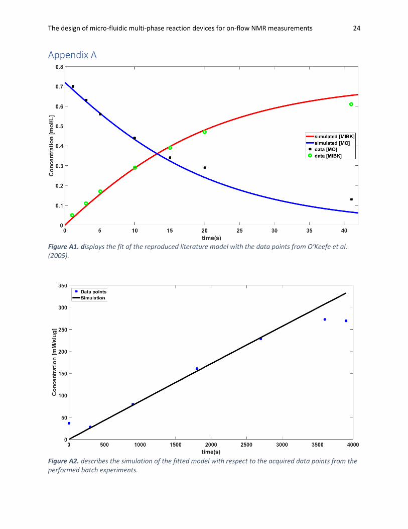
Appendix A
Figure A1. displays the fit of the reproduced literature model with the data points from O’Keefe et al. (2005).
Figure A2. describes the simulation of the fitted model with respect to the acquired data points from the performed batch experiments.


![Multi-physics Simulational Analysis of a Novel PCR Micro ...€¦ · either the thermal-fluidic aspect [1, 2] or the reaction kinetics [3] of PCR devices. In this paper, a multi-physics](https://img.pdfslide.us/doc/110x75/5ffe61ce8183c429f831ce70/multi-physics-simulational-analysis-of-a-novel-pcr-micro-either-the-thermal-fluidic.jpg)