Embed Size (px)
Citation preview
The Design and Small-Scale Fabricationof Precision Desktop Lathe Components
by
Brian Philip Demers
MASSACHUSETTS INSTITUTEOF TECHNOLOGY
SEP 16 2009
LIBRARIES
Submitted to the Department of Mechanical Engineering inPartial Fulfillment of the Requirements for the Degree of
Bachelor of Science
ARCHIVESat the
Massachusetts Institute of Technology
June 2009
C 2009 Massachusetts Institute of Technology. All rights reserved.
Signature of AuthorDepartment of M ical EngXring
8 2009
Certified by
Soate ProfessorSMartin A pper
of Mechanical EngineeringThesis Supervisor
Accepted byS -- John Lienhard V
S Co s Professor of Mechanical EngineeringChairman, Undergraduate Thesis Committee

Page 2 of 37
The Design and Small-Scale Fabricationof Precision Desktop Lathe Components
by
Brian Demers
Submitted to the Department of Mechanical Engineering on May 8th, 2009 inPartial Fulfillment of the Requirements for the Degree of Bachelor of Science in
Mechanical Engineering
ABSTRACT
An evaluation was carried out on the design and fabrication techniques of thecomponents provided to students in MIT's 2.72 class. These components are used by thestudents in the production of a fully-functional precision desktop lathe. Changes to theexisting design of the provided components were made to produce higher quality parts, tolower costs of fabrication, and to increase the diversity of the manufacturing processesutilized in the class.
Much of the study was devoted to the design and production of sand cast parts. Patternsfor these components were printed using stereo lithography, and then cast at a localfoundry. Using a carefully designed process plan, the critical interface features of thesand cast parts were machined to their final dimensions. Specific attention was paid tothe fixtures clamping these non-uniform parts to ensure accurate datums duringmachining.
Thesis Supervisor: Martin Culpepper
Title: Associate Professor of Mechanical Engineering
Page 3 of 37

Page 4 of 37

Acknowledgements
My sincere thanks to both Professor Culpepper and to Jon Hopkins, the course TA, for
their advice and support throughout the semester. Their guidance and input has been
critical in getting the lathe components successfully manufactured on time, and within
spec. I am also grateful to the lab instructor, Patrick McAtamney, for all the time and
effort he has dedicated to the class, and to the students. His work with both me and the
students has been critical in the fabrication process. Lastly, I would also like to
acknowledge the Spring 2009 2.72 students, who have provided valuable feedback on my
work as they have adventured through the course.
Page 5 of 37

Page 6 of 37

Table of Contents
ABSTRACT ........................................................................................ ........ 3Acknowledgem ents ................................................................................................... 5Table of Contents ................................................................................................................ 7List of Figures................................................................................................................. 9Chapter 1: Introduction ............................................................ ................................. 11
1.1 Background ............................................ ....................................................... 111.2 The Com ponents...........................................................13
Chapter 2: The Head and Tail Stocks ..................................... ...................... 162.1 D esign ........................................ ........................................................ ......... 162.2 Fabrication ......................................................................................................... 17
Chapter 3: The Structure Tube A ssem bly ..................................... ..... ............ 233.1 D esign ................................................. 233.2 Fabrication ............................................. ....................................................... 25
Chapter 4: The Carriage ......................................................................... ...... ... 264.1 D esign ................................................. 264.2 Fabrication ............................................. ....................................................... 30
Chapter 5: Conclusions ........................................... ................................................ 35References .................................................................................................................... 37
Page 7 of 37

Page 8 of 37

List of Figures
FIGURE 1.1a: THE 2.72 LATHE ....................................................... 12FIGURE 1. lb: FOUR MAIN COMPONENTS ...................................... ......... 13FIGURE 1.2: ANNOTATED ISOMETRIC OF LATHE ............................................. 15FIGURE 2.1: AS-CAST VS. POST-MACHINED HEAD STOCKS .......................... 17FIGURE 2.2a: THE HEAD AND TAIL STOCK PATTERNS ...................................... 18FIGURE 2.2b: MILL VICE SIDE VIEW ...................................................................... 22FIGURE 3.1a: LEAD SCREW ASSEMBLY CROSS-SECTION .............................. 23FIGURE 3.lb: ANNOTATED PRELOAD MECHANISM CROSS-SECTION ............ 24FIGURE 4.1a: CARRIAGE FROM TOP .......................................... ............. 28FIGURE 4.lb: CARRIAGE FROM BOTTOM ............................................................ 29FIGURE 4.1c: AS-CAST CARRIAGE ..................................... .............. 30FIGURE 4.2a: JIG INSTRUCTIONS PAGE 1 ....................................... ......... 33FIGURE 4.2b: JIG INSTRUCTIONS PAGE 2...................................... .......... 34
Page 9 of 37

Page 10 of 37
Chapter 1: Introduction
1.1 Background
MIT's 2.72 class focuses on the area of mechanical design. To assist in the learning
experience, students design, fabricate, and test miniature high-performance lathes. The
task of designing and fabricating a desktop lathe in its entirety would be a huge challenge
for any student. In order to do so in a semester, 2.72 focuses on key components in the
machine tool. While students are expected to understand the lathe's function as a whole,
certain parts, like the head and tail stocks, are provided semi-complete. They require
only small modifications in finishing and mounting to integrate with the student designs.
Taking the burden of design and fabrication of these parts off of the students allows them
greater time to explore their own designs for critical machine components. The demand
for these pre-fabricated parts, in terms of the class, is very strong. Without them, it
would be incredibly difficult for the students to measure or evaluate their designs. The
base components provided in 2.72 are virtually necessary to complete the course on time.
Allowing each student to build his or her own lathe requires that as many as 40 lathes
worth of prepared parts be manufactured for the class during the semester. The purpose
of the following work has been to comfortably allow this scale of production to occur at
low cost and at a quality suitable for the needs of the class, and to provide better
documentation to the students, so that they may be properly prepared to integrate their
own designs with the provided components. A growing number of students are electing
to take the 2.72 class each year. With this expansion, the demand for the pre-fabricated
Page 11 of 37
components, and therefore, the importance of these thesis results, continues to increase.
The impact of this work should be seen in both higher quality components, and the wide
availability of these components, such that every 2.72 student may elect to fabricate
his/her own lathe.
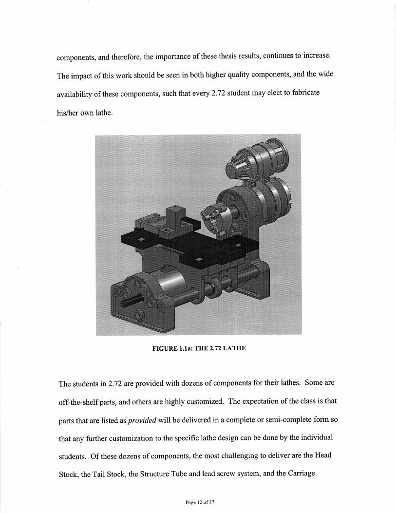
FIGURE 1.1a: THE 2.72 LATHE
The students in 2.72 are provided with dozens of components for their lathes. Some are
off-the-shelf parts, and others are highly customized. The expectation of the class is that
parts that are listed as provided will be delivered in a complete or semi-complete form so
that any further customization to the specific lathe design can be done by the individual
students. Of these dozens of components, the most challenging to deliver are the Head
Stock, the Tail Stock, the Structure Tube and lead screw system, and the Carriage.
Page 12 of 37
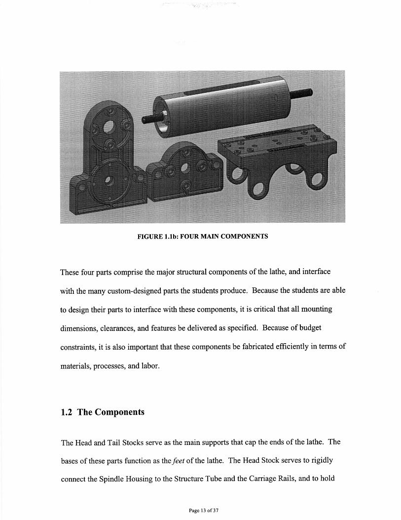
FIGURE 1.1b: FOUR MAIN COMPONENTS
These four parts comprise the major structural components of the lathe, and interface
with the many custom-designed parts the students produce. Because the students are able
to design their parts to interface with these components, it is critical that all mounting
dimensions, clearances, and features be delivered as specified. Because of budget
constraints, it is also important that these components be fabricated efficiently in terms of
materials, processes, and labor.
1.2 The Components
The Head and Tail Stocks serve as the main supports that cap the ends of the lathe. The
bases of these parts function as the feet of the lathe. The Head Stock serves to rigidly
connect the Spindle Housing to the Structure Tube and the Carriage Rails, and to hold
Page 13 of 37

these components in alignment with any flat surface on which the lathe rests. The Tail
Stock rigidly connects the opposite end of the Structure Tube and Carriage Rails, and
also holds these components in alignment.
The Structure Tube provides the main rigid support between the Head and Tail Stocks. It
also contains a lead screw that drives the Z-motion of the lathe's carriage. Sub-
components of the Structure Tube assembly constrain the movement of the lead screw to
allow its rotation to effect translation of the Carriage.
The Carriage supports the Cross-feed Flexure and Tool-Holder, and slides on the
Carriage Rails through the use of bronze bushings. It is also coupled to the lead screw
within the Structure Tube by a lead screw flexure. The Carriage must rigidly pass the
cutting forces of the tool through the rails and into the Head and Tail Stocks.
Page 14 of 37
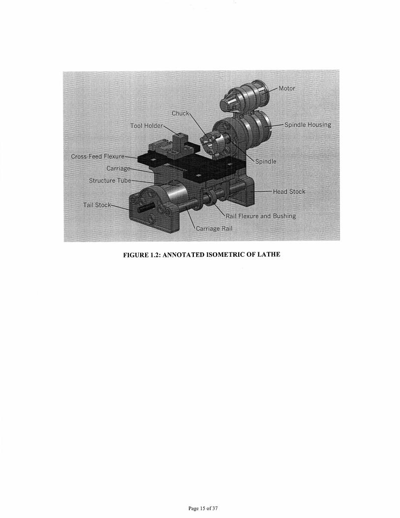
FIGURE 1.2: ANNOTATED ISOMETRIC OF LATHE
Page 15 of 37
Chapter 2: The Head and Tail Stocks
2.1 Design
In previous years, a number of designs for the Head and Tail Stocks have been attempted.
Some have been water-jet-cut. Some have been machined. More recently, a version was
designed to be sand-cast and finished with a CNC mill. Given the success of this design,
it was most efficient to optimize its fabrication and leave it dimensionally identical. Sand
Casting is a particularly cost effective method of producing parts near their final
geometry. The tooling costs are low, and the process is capable of producing fairly
complex parts (Shigley, Mischke, & Budynas, 2006, p. 274).
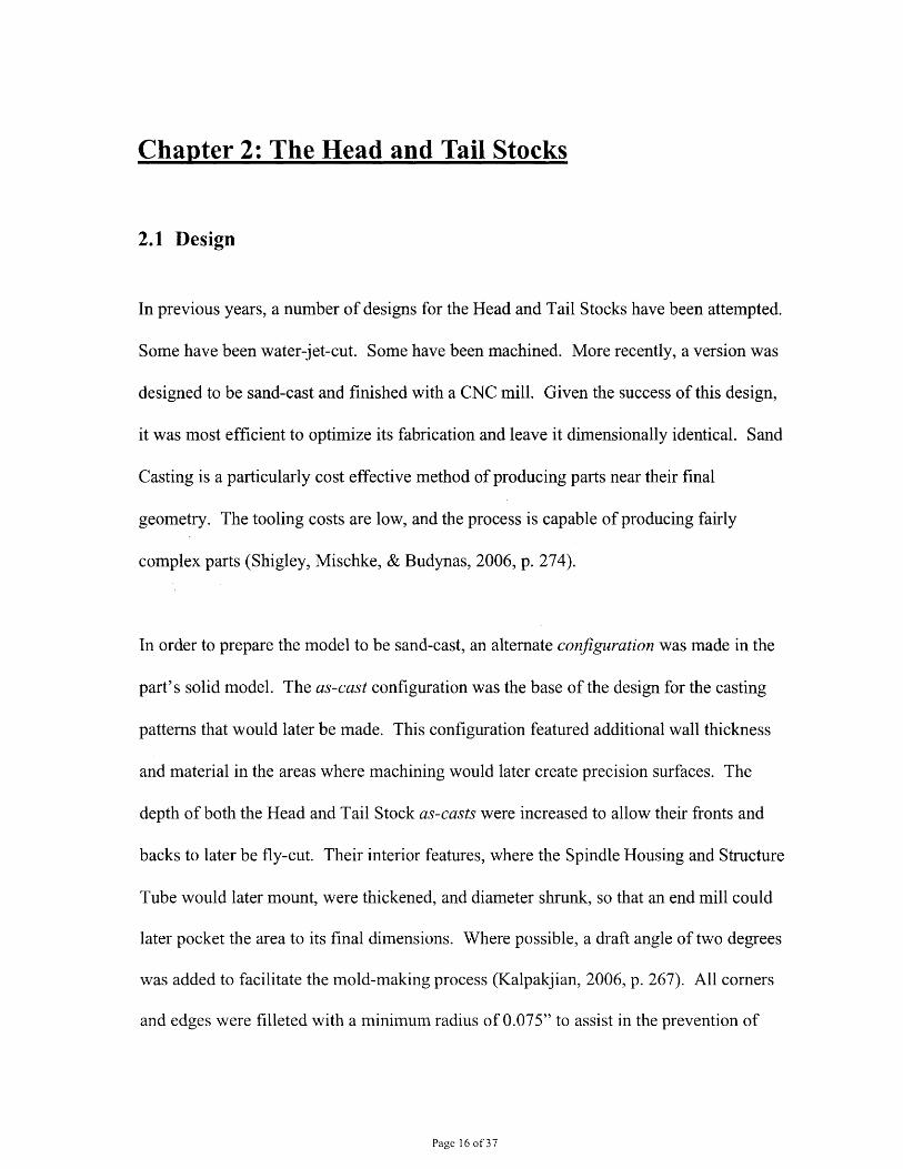
In order to prepare the model to be sand-cast, an alternate configuration was made in the
part's solid model. The as-cast configuration was the base of the design for the casting
patterns that would later be made. This configuration featured additional wall thickness
and material in the areas where machining would later create precision surfaces. The
depth of both the Head and Tail Stock as-casts were increased to allow their fronts and
backs to later be fly-cut. Their interior features, where the Spindle Housing and Structure
Tube would later mount, were thickened, and diameter shrunk, so that an end mill could
later pocket the area to its final dimensions. Where possible, a draft angle of two degrees
was added to facilitate the mold-making process (Kalpakjian, 2006, p. 267). All comers
and edges were filleted with a minimum radius of 0.075" to assist in the prevention of
Page 16 of 37
cold cracking (Shigley et al. 2006, p. 274). Figure 2.1 illustrates the as-cast and post-
machined configurations for one side of the Head Stock.
FIGURE 2.1: AS-CAST VS. POST-MACHINED HEAD STOCKS
2.2 Fabrication
The foundry selected for production preferred to work with a match-plate type pattern,
where two halves of the pattern are secured to a single wooden plate (Kalpakjian, 2006, p
267). The as-cast configurations were converted to a pattern design by assigning a plane
around which the part could be divided in two semi-equal pieces. Fortunately the plane
down the center of the parts contained no features and provided a simple location to add
the mold parting line. See Figure 2.2a for the four parts that comprise the Head and Tail
Stock patterns.
Page 17 of 37
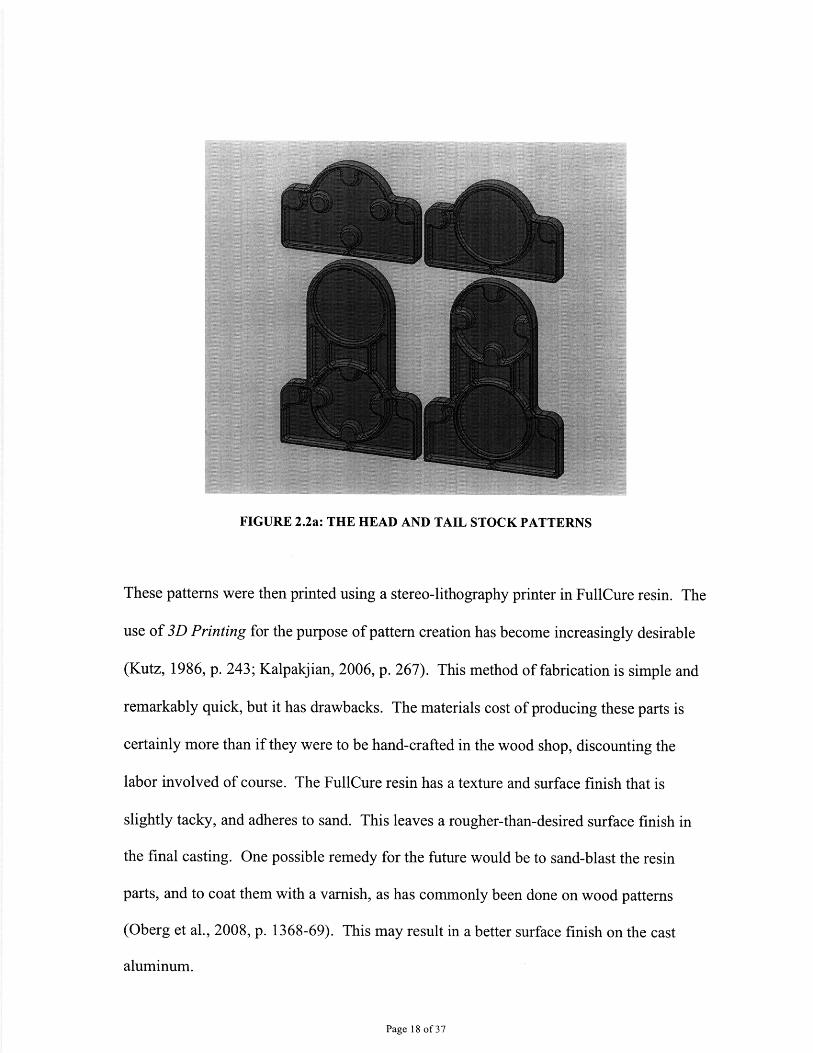
FIGURE 2.2a: THE HEAD AND TAIL STOCK PATTERNS
These patterns were then printed using a stereo-lithography printer in FullCure resin. The
use of 3D Printing for the purpose of pattern creation has become increasingly desirable
(Kutz, 1986, p. 243; Kalpakjian, 2006, p. 267). This method of fabrication is simple and
remarkably quick, but it has drawbacks. The materials cost of producing these parts is
certainly more than if they were to be hand-crafted in the wood shop, discounting the
labor involved of course. The FullCure resin has a texture and surface finish that is
slightly tacky, and adheres to sand. This leaves a rougher-than-desired surface finish in
the final casting. One possible remedy for the future would be to sand-blast the resin
parts, and to coat them with a varnish, as has commonly been done on wood patterns
(Oberg et al., 2008, p. 1368-69). This may result in a better surface finish on the cast
aluminum.
Page 18 of 37
At the foundry, the half-patterns were pinned together for alignment, and mounted
separately on the match-plate wood. Gates, risers, runners, and sprue features were
fashioned from wood and added to the patterns to allow material flow and venting
(Kalpakjian, 2006, p 265). Once green sand had been packed around the half-patterns,
they were removed, and the two boxes of sand (the cope and drag) were joined and
locked together. Aluminum was poured through the Sprue, and filled the voids within the
sand pattern. The Head and Tail Stocks were cast side-by-side in the same cope/drag set
for time efficiency.
The cast parts were first band-sawed from the gates and risers, and then ground and
sandblasted to remove imperfections. These processes, although necessary, compromise
the integrity of the outer edges of the part. However, these abrasive methods are less
likely to damage to the internal features most critical to the parts (Oberg, & McCauley,
2008, p 1367). Because of these cleanup operations, the comers were oftentimes not
perpendicular, and edges not parallel. Given the primary purpose of the Head and Tail
Stocks, it was of utmost importance that their critical mounting dimensions be accurate.
This would be taken care of by the next process steps. The inherent benefit of a
machined casting is that the machine tool can form all critical features. Doing so allows
tight control over their relative locations, tolerating minor misalignments of the bulk cast
material (Kutz, 1986, p. 269). The features of the Head and Tail Stock, however,
required machining on both the front and back of the parts. Without access to a fourth-
Page 19 of 37
axis mill, it was necessary to rotate and re-clamp the parts to complete the machining
process. Doing so meant that a robust set of alignment features needed to be identified.
On the parts as they were cast, the edges most accurate to the design were the front and
back faces, which had undergone little to no grinding at the foundry. The base, or foot of
the parts was the second strongest alignment feature. Using these surfaces, the Head and
Tail Stocks were mounted upright in a vice on a Bridgeport mill. A flat was fly cut in
each at a specified height off of the base of the vice. This flat at the top of the parts
would later provide a mounting surface. Due to the variability in the parts, the depth of
cut in this operation was different on each part. Some required two depth cuts to ensure a
proper surface finish on the finish cut. The parts were then inverted, and balanced on the
new flat. The front and back faces were again clamped for alignment in the mill's vice.
The foot of both parts was fly cut at a specified height. This time, due to the prior
operation, the depth of cut was consistent between parts, yielding parts that now all had
the same height.
The height of the machined features relative to the machined base was the most critical
issue, so that the lathe, when assembled, would sit square on a flat surface. The left-right
alignment of the features was less critical, so long as it was consistent front-to-back on
the parts. In consideration of the time required, no machined flats were made on the left
and right edges of the parts. Rather, a fixture was designed for the mill that would aid in
alignment. Custom soft jaws were machined with a step surface to accommodate the
Head and Tail Stocks in a laid-down position. The y-axis was zeroed at the top, non-
Page 20 of 37

moving jaw. The foot of the parts was placed against this jaw. The z-axis was zeroed at
the base of the vice jaw's step. This allowed the parts to be fly-cut to a known,
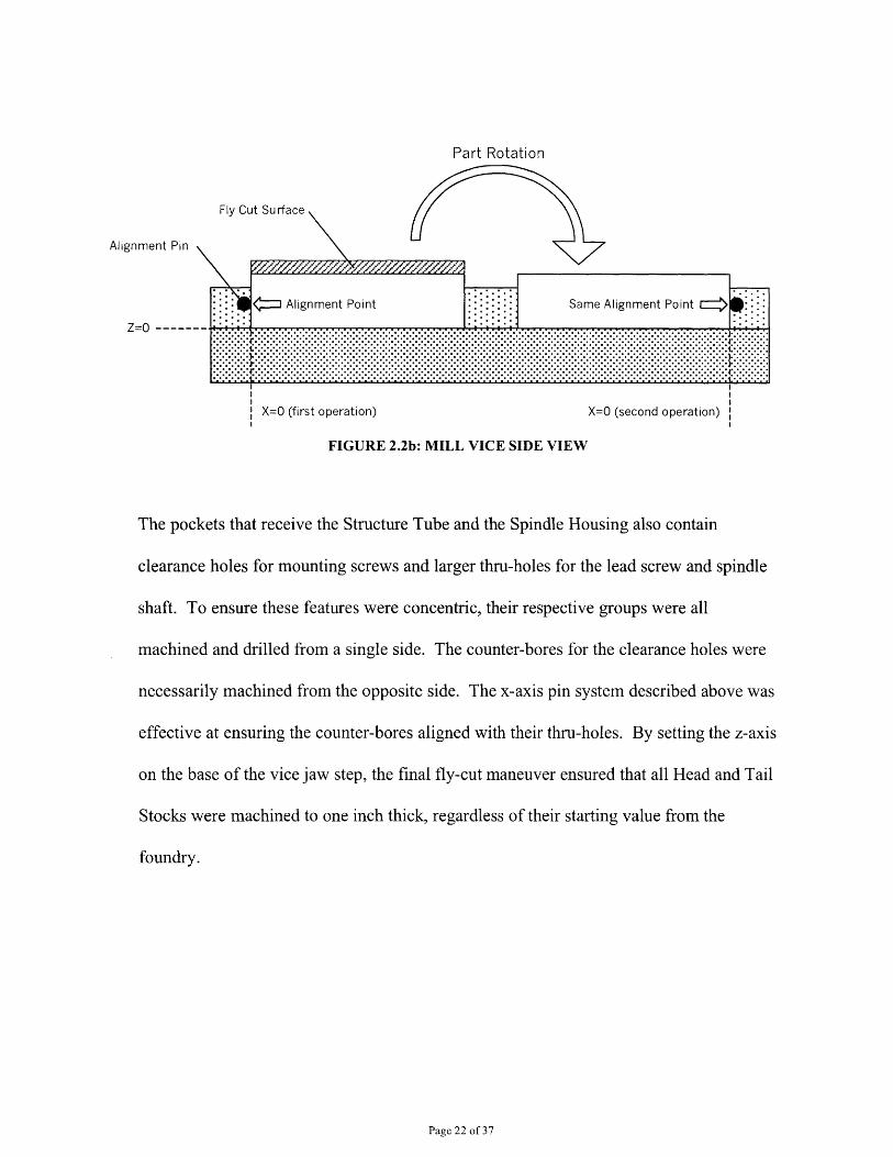
repeatable thickness. The x-axis alignment was more difficult, as it had to accommodate
the rotation of the parts. The custom jaws featured two alignment pins to fix the x-axis of
the part. See Figure 2.2b. The part was first loaded in the left configuration. On the foot
end of the part, an alignment pin contacted the edge, providing an x-axis datum. After
the part had been fly cut, and otherwise machined, the part was rotated, as in Figure 2.2b,
to its opposite side. A second alignment pin contacted the part in the same datum
location. This defined a new coordinate system in which to machine the opposite side of
the part. Since the edges on which the datum was set were not always perpendicular to
the base of the vice, it was critical that the pin contact the same exact point, and not just
any point, on the edge of the part. This was ensured by placing the first locating pin at a
z-height such that when the part was machined and rotated, the second pin would contact
the same datum point as the first pin. This too is illustrated in Figure 2.2b. This operation
was specifically enabled by the choice to set the z-axis datum on the bottom of the jaw's
step, rather than on the top of the part.
Page 21 of 37
Part Rotation
Alignment Pin
Z=O -----
Fly Cut Surface
' J Alignment Point Same Alignment Point E I
X=O (first operation) X=O (second operation)
FIGURE 2.2b: MILL VICE SIDE VIEW
The pockets that receive the Structure Tube and the Spindle Housing also contain
clearance holes for mounting screws and larger thru-holes for the lead screw and spindle
shaft. To ensure these features were concentric, their respective groups were all
machined and drilled from a single side. The counter-bores for the clearance holes were
necessarily machined from the opposite side. The x-axis pin system described above was
effective at ensuring the counter-bores aligned with their thru-holes. By setting the z-axis
on the base of the vice jaw step, the final fly-cut maneuver ensured that all Head and Tail
Stocks were machined to one inch thick, regardless of their starting value from the
foundry.
Page 22 of 37
I . - - .- -
.: ..: ..: ... .... .. .............................:.: ... ..........................:.:.:.*.:.:..:.:.:.:. *..:.: . .. ... :. .. . . :...:. .. :.:.* . :.:.:.*.:.:.* ..::. .......... . :.. . :. ... :.......... .... .. .......................... .............. . ..... . ..... *.. . -.*... .. *. . -... ......... . *....... .:.*.*..-.*... ......... : .*... . : .:. .. -.:.-. ::.*.- ..: : . :. . :. :.- :. :. :°°°.°.*.*.°4*.°.*.*.°.*.°.*,° *.°.*.*.*.°.*-*.*.°°°.*.*.*.°.*-°.*.*-*-°.*.*.*°°-*°*.*.*.*.*.*.-.*.*.°. .*.*.°.*.*.*.*.*°*.*.*.•.*.-o-o*.*.O.*o*oO.*.*-*.*.*.*,*o*.*o*o*.O.*OO°*,
'' I 1 '
Chapter 3: The Structure Tube Assembly
3.1 Design
The assembly connecting the Head and Tail Stocks and providing lead screw operation in
previous design iterations was costly, and required many complex parts. In this design,
the Structure Tube was simplified to one tube, and two small plates, in addition to lead
screw hardware. This cut costs in materials, and greatly reduced manufacturing time.
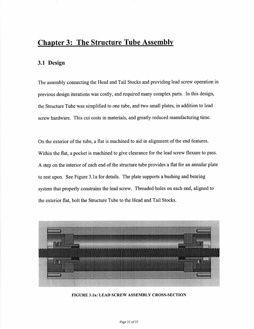
On the exterior of the tube, a flat is machined to aid in alignment of the end features.
Within the flat, a pocket is machined to give clearance for the lead screw flexure to pass.
A step on the interior of each end of the structure tube provides a flat for an annular plate
to rest upon. See Figure 3.1 a for details. The plate supports a bushing and bearing
system that properly constrains the lead screw. Threaded holes on each end, aligned to
the exterior flat, bolt the Structure Tube to the Head and Tail Stocks.
FIGURE 3.1a: LEAD SCREW ASSEMBLY CROSS-SECTION
Page 23 of 37
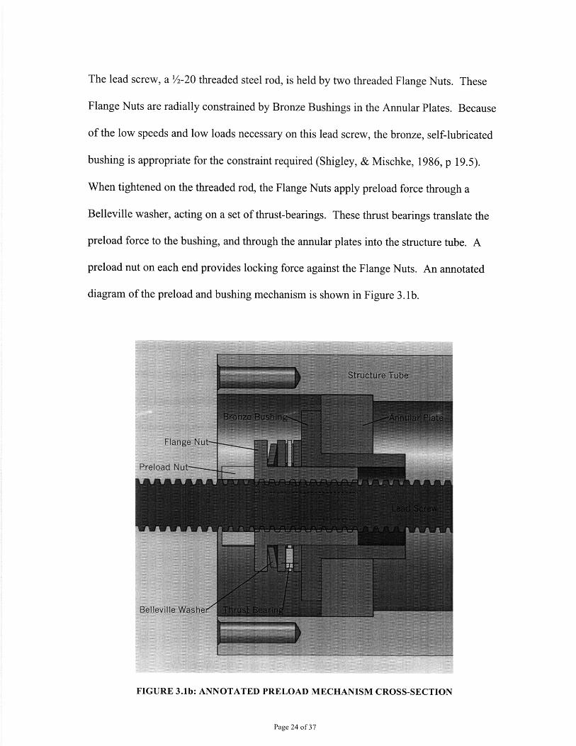
The lead screw, a /2-20 threaded steel rod, is held by two threaded Flange Nuts. These
Flange Nuts are radially constrained by Bronze Bushings in the Annular Plates. Because
of the low speeds and low loads necessary on this lead screw, the bronze, self-lubricated
bushing is appropriate for the constraint required (Shigley, & Mischke, 1986, p 19.5).
When tightened on the threaded rod, the Flange Nuts apply preload force through a
Belleville washer, acting on a set of thrust-bearings. These thrust bearings translate the
preload force to the bushing, and through the annular plates into the structure tube. A
preload nut on each end provides locking force against the Flange Nuts. An annotated
diagram of the preload and bushing mechanism is shown in Figure 3. lb.
FIGURE 3.1b: ANNOTATED PRELOAD MECHANISM CROSS-SECTION
Page 24 of 37
This simplified design requires only the custom manufacture of the Flange Nuts, the
Annular Plates, and the Structure Tube.
3.2 Fabrication
The Structure Tube itself was contracted out to a local machine shop for fabrication. All
machining was completed on CNC equipment. The Flange Nuts were also contracted
out, and were turned on a CNC lathe.
The Annular Plates were water-jet cut from aluminum sheet in the MIT Machine Shop in
a batch operation.
All other parts were specified as off-the-shelf parts, and were purchased from various
suppliers.
Page 25 of 37
Chapter 4: The Carriage
4.1 Design
The Carriage featured a clean-slate redesign in this model. Previous versions of the
Carriage were made from water-jet-cut aluminum and a polymer block. Although the
design was very easy to make, the cost of the abrasive and maintenance in the water-jet
cutting operation as well as the material costs for the polymer were not justified by the
performance of the Carriage. The use of the polymer, in particular, left a soft base in
which to bolt the cross-feed-flexure. These bolts often stripped the threads in the
polymer during use.
Given the plethora of lathes that have been made in prior years, it made sense to keep all
the critical mounting dimensions and positions the same as previous models. Therefore,
parts like flexures could be interchangeable between models for testing or
experimentation. The mounting locations included: supporting two bushings on the near-
side rail, bolting to the lead screw flexure, bolting to the rail flexure, bolting to the cross-
feed flexure. The rail flexure served to prevent over-constraint in the carriage mount;
only one side of the carriage needed to rigidly mount through bushings to the rail.
However, in order to simplify the manufacturing process, and to ensure quality parts, the
Carriage was designed to be symmetrical, and reversible. In doing so, any shrinkage or
errors from the casting process would be symmetric about the middle of the part. Like
the Head and Tail Stocks, the Carriage was designed to be sand-cast and then finish-
Page 26 of 37
machined. Sand casting was chosen for its low cost, and its ability to make complex
parts in an inexpensive manner (Shigley et al., 2006, p. 274). Sand casting is especially
economical for parts of small to medium runs, as the tooling costs are very low
(Kalpakjian, 2006, p. 264). By casting the near-net shape, only a small amount of
material needed to be removed by finish machining.
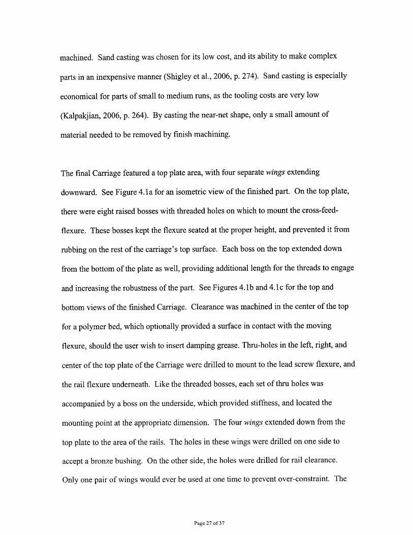
The final Carriage featured a top plate area, with four separate wings extending
downward. See Figure 4.1a for an isometric view of the finished part. On the top plate,
there were eight raised bosses with threaded holes on which to mount the cross-feed-
flexure. These bosses kept the flexure seated at the proper height, and prevented it from
rubbing on the rest of the carriage's top surface. Each boss on the top extended down
from the bottom of the plate as well, providing additional length for the threads to engage
and increasing the robustness of the part. See Figures 4. lb and 4.1 c for the top and
bottom views of the finished Carriage. Clearance was machined in the center of the top
for a polymer bed, which optionally provided a surface in contact with the moving
flexure, should the user wish to insert damping grease. Thru-holes in the left, right, and
center of the top plate of the Carriage were drilled to mount to the lead screw flexure, and
the rail flexure underneath. Like the threaded bosses, each set of thru holes was
accompanied by a boss on the underside, which provided stiffness, and located the
mounting point at the appropriate dimension. The four wings extended down from the
top plate to the area of the rails. The holes in these wings were drilled on one side to
accept a bronze bushing. On the other side, the holes were drilled for rail clearance.
Only one pair of wings would ever be used at one time to prevent over-constraint. The
Page 27 of 37
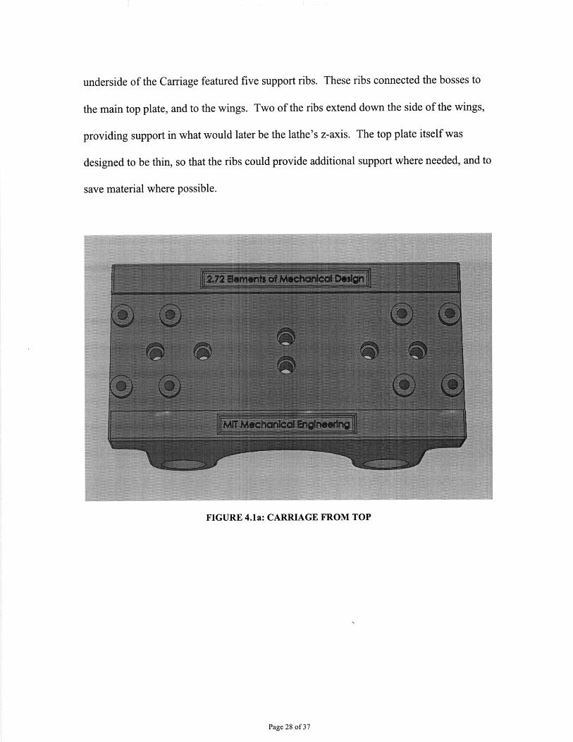
underside of the Carriage featured five support ribs. These ribs connected the bosses to
the main top plate, and to the wings. Two of the ribs extend down the side of the wings,
providing support in what would later be the lathe's z-axis. The top plate itself was
designed to be thin, so that the ribs could provide additional support where needed, and to
save material where possible.
FIGURE 4.1a: CARRIAGE FROM TOP
Page 28 of 37
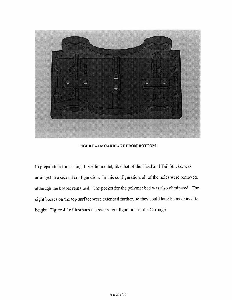
FIGURE 4.1b: CARRIAGE FROM BOTTOM
In preparation for casting, the solid model, like that of the Head and Tail Stocks, was
arranged in a second configuration. In this configuration, all of the holes were removed,
although the bosses remained. The pocket for the polymer bed was also eliminated. The
eight bosses on the top surface were extended further, so they could later be machined to
height. Figure 4.1 c illustrates the as-cast configuration of the Carriage.
Page 29 of 37
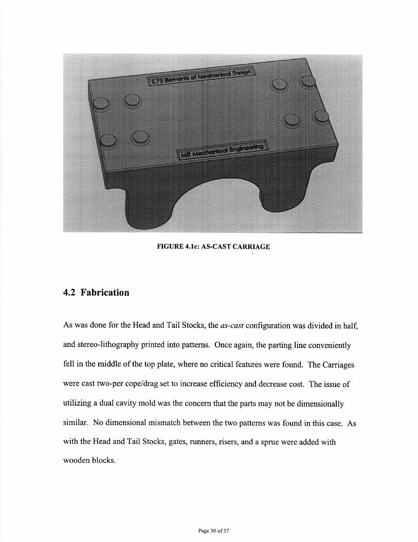
FIGURE 4.1c: AS-CAST CARRIAGE
4.2 Fabrication
As was done for the Head and Tail Stocks, the as-cast configuration was divided in half,
and stereo-lithography printed into patterns. Once again, the parting line conveniently
fell in the middle of the top plate, where no critical features were found. The Carriages
were cast two-per cope/drag set to increase efficiency and decrease cost. The issue of
utilizing a dual cavity mold was the concern that the parts may not be dimensionally
similar. No dimensional mismatch between the two patterns was found in this case. As
with the Head and Tail Stocks, gates, runners, risers, and a sprue were added with
wooden blocks.
Page 30 of 37

To complete the Carriages, they needed to be finish-machined. Unlike the Head and Tail
Stocks, most of the features could be machined from one clamped position. This
somewhat simplified the fixturing process. The carriages were held in their standard
orientation in a set of tall jaws. The bottom of the wings served as the z-axis zero. A
stop on the vice engaged with the left end of the top plate to serve as the x-axis zero. A
CNC routine faced off the eight bosses, drilled them, and tapped them. It also pocketed
the polymer bed clearance, drilled the six clearance holes, and pocketed their counter-
bores. An engraving tool was used for a custom engraving during this routine. The order
of machining operations was optimized to minimize the number of tool changes
necessary.
Because all of the interface surfaces were machined, the accuracy of the z-axis zero was
not particularly important in this operation, except that if it was too low, the bosses would
be fly-cut below the surface of the casting. If this were the case, the flexure would not sit
proud of the casting, and might rub in certain locations. This issue in future attempts
could be corrected in two ways: Including a fly-cut pass that sinks the top surface outside
of the polymer bed pocket. This would guarantee clearance. Another possibility would
be to invert the carriages before machining, and to machine flats in the bottom of the
wings, in a way similar to what is done with the Head and Tail Stocks. The bosses do
appear to be the best datum surface on the cast parts. Adding an additional fly cut pass
on the top side would be most efficient labor-wise.
Page 31 of 37

The next feature to be machined was the flats on the underside to which the flexures
mounted. These flats were designed to be exactly one inch below the top of the bosses.
Once the CNC process was complete, a user could invert the part in a Bridgeport mill.
After setting a z-axis zero on the base of the vice, the user could fly-cut at one inch to
produce these flats.
Lastly, the bushing and clearance holes for the rails needed to be drilled. The location of
these holes relative to the other machined surfaces was critical to the smooth operation of
the lathe. When the Carriage was oriented for drilling, none of the machined features
were easily accessible to set an x-axis zero from. Therefore, a locating jig was necessary.
The jig consisted of a 1/2" thick plate with two pins. These pins engaged with the counter-
bores in the top surface. One end of the jig was machined at a precise distance from the
pins. This provided an accessible surface to slide against a stop in the Bridgeport mill.
After one side of holes was drilled, the Carriage could be removed and flipped. The use
of the jig ensured that the holes on both sides were concentric, and centered around the
machined features on the top surface. Figures 4.2a and 4.2b illustrate the directions
provided to students to assist in using the jig.
Page 32 of 37
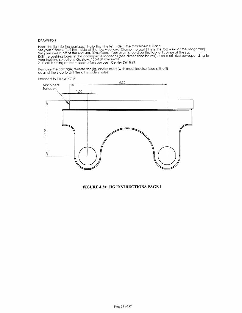
DRAWING 1
Insert the jig into the carriage. Note that the left side is the machined surface.Set your Y-zero off of the inside of the top vice jaw. Clamp the part (this is the top view of the Bridgeport).Set your X-zero off of the MACHINED surface. Your origin should be the top left corner of the jig.Drill the bushing bores in the appropriate locations (see dimensions below). Use a drill size corresponding toyour bushing selection. Go slow, 100-150 rpm max!!!A 1" drill is sitting at the machine for your use. Center Drill first!
Remove the carriage, reverse the jig, and reinsert (with machined surface still left)against the stop to drill the other side's holes.
Proceed to DRAWING 2
FIGURE 4.2a: JIG INSTRUCTIONS PAGE 1
Page 33 of 37
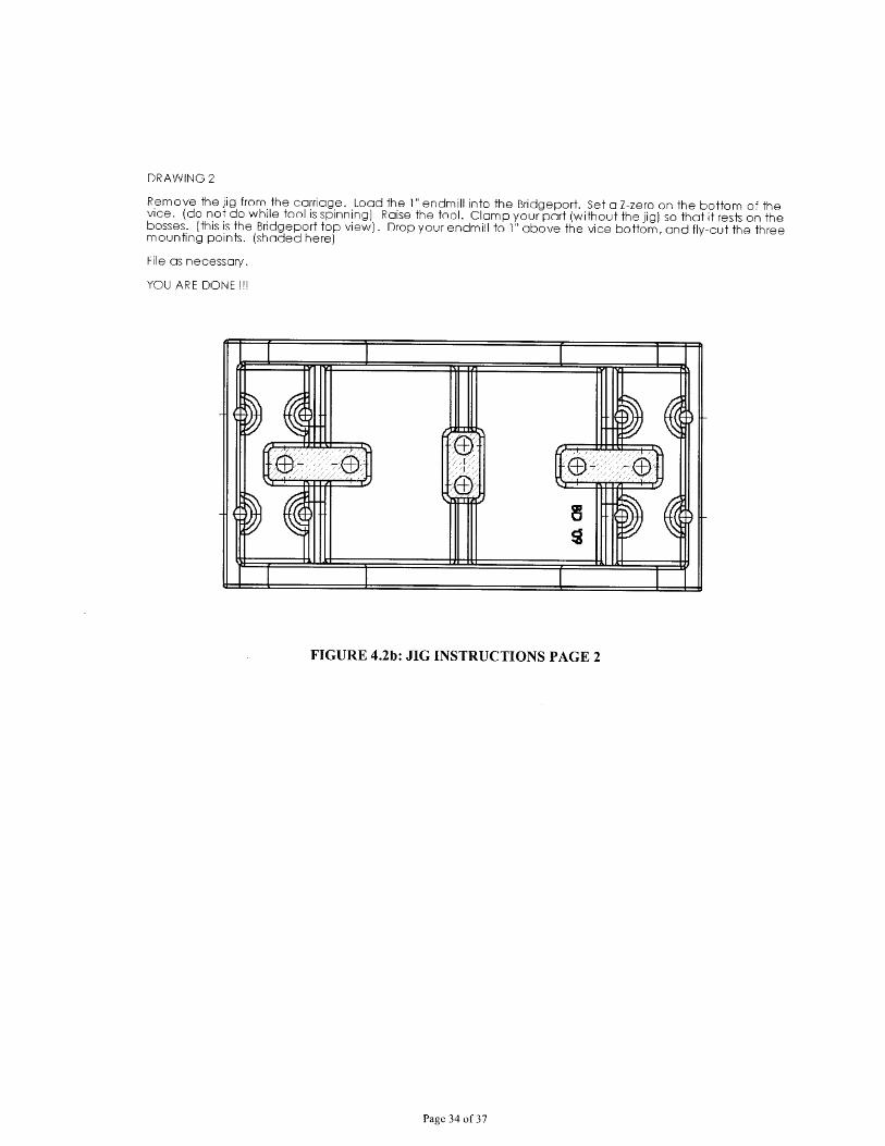
DRAWING 2
Remove the jig from the carriage. Load the 1" endmill into the Bridgeport. Set a Z-zero on the bottom of thevice. (do not do while tool is spinning) Raise the tool. Clamp your part (without the jig) so that it rests on thebosses. (this is the Bridgeport top view). Drop your endmill to 1" above the vice bottom, and fly-cut the threemounting points. (shaded here)
File as necessary.
YOU ARE DONE !!!
FIGURE 4.2b: JIG INSTRUCTIONS PAGE 2
Page 34 of 37
Chapter 5: Conclusions
The students in the Spring 2009 2.72 class have been able to successfully assemble their
lathes with the new provided components. No performance or fit issues have been
reported. The number of cast parts used, which approached 120 for this course alone, did
prove to be a large burden on the course staff and instructors, however. Although the
machining process was automated, the loading and unloading of the parts was not. The
time interval between parts, ranging from 10 to 20 minutes, depending on the part, was
long enough to necessitate that Pat, the lab instructor, attend to other students. It proved
difficult to keep the parts consistently flowing through the CNC process. Although cost
would certainly be an issue, the class instructors may wish to have the CNC work done
by an outside shop, as was done for other parts like the Structure Tube. Another option
for consideration would be the hiring of an undergraduate to complete all machining
operations during the Spring Break week. If the parts were consistently loaded into the
mill, the entire batch could likely be completed in 5 days.
In addition to the delivery of the parts for this semester, an updated series of solid models
and drawings has also been provided to the class and instructors. Along with these
models are the CAM programming required to perform the cleanup operations on the cast
parts. These files, along with the actual patterns used for the sand casting process, will
minimize the up-front labor necessary to fulfill the fabrication of these parts for the
Spring 2010 class.
Page 35 of 37

Lastly, the students and instructors have been provided with photo and video
documentation of much of the fabrication processes, including sand casting and CNC
machining of the Head Stocks, Tail Stocks, and the Carriages. This documentation
should help the students in future classes better understand the origin of the components
and materials that they are working with.
Page 36 of 37
References
Kalpakjian, S. (2006). Manufacturing engineering and technology. Upper Saddle River,NJ: Pearson/Prentice Hall.
Kutz, M. (1986). Mechanical engineers' handbook. New York: Wiley.
Oberg, E., & McCauley, C. J. (2008). Machinery's handbook: A reference book for themechanical engineer, designer, manufacturing engineer, draftsman, toolmaker,and machinist. New York: Industrial Press.
Shigley, J. E., Mischke, & C. R., Budynas, R. G. (2006). Shigley's mechanicalengineering design. New York: McGraw-Hill Higher Education.
Shigley, J. E., & Mischke, C. R. (1986). Standard handbook of machine design. NewYork: McGraw-Hill.
Page 37 of 37