Embed Size (px)
Citation preview
To appear in Journal of Parallel and Distributed Computing
The Design and Performance Evaluation of theDI-multicomputer �Lynn Choi Andrew A. ChienCenter for Supercomputing R & D Department of Computer ScienceUniversity of Illinois University of IllinoisUrbana, IL 61801-1351 Urbana, IL [email protected] [email protected](217)333-0969 (217)333-6844(217)244-1351 (fax) (217)244-6500 (fax)AbstractIn this paper, we propose a new multicomputer node architecture, the DI-multicomputer whichuses packet routing on a uniform point-to-point interconnect for both local memory access and intern-ode communication. This is achieved by integrating a router onto each processor chip and eliminat-ing the memory bus interface. Since communication resources such as pins and wires are allocateddynamically via packet routing, the DI-multicomputer is able to maximize the available communica-tion resources, providing much higher performance for both intra-node and internode communication.Multi-packet handling mechanisms are used to implement a high performance memory interface basedon packet routing. The DI-multicomputer network interface provides e�cient communication for bothshort and long messages, decoupling the processor from the transmission overhead for long messageswhile achieving a minimum latency for short messages. Trace-driven simulations based on a suiteof message passing applications show that the communication mechanisms of the DI-multicomputercan achieve up to four times speedup when compared to existing architectures.1 IntroductionParallel computer systems contain processors, memory modules, and interconnection networks which tiethem together. While many parallel systems have impressive peak processing rates, they cannot approachmaximum performance on application programs unless computation and communication performanceare balanced. In many cases, the imbalance between computation and communication performanceis not due to poor performance of the core network, but rather a poor coupling of the network andthe processing node. In this paper, we address design issues of a multicomputer node architecture,particularly the network interface and its interaction with the local memory hierarchy. The goal ofa multicomputer node architecture is to support high performance in both message passing and localcomputation.Two major varieties of multicomputer node architecture have emerged (see Figure 1). The �rst inter-faces the network to a local bus, allowing network-memory data transfers and preserving microprocessorinterface compatibility. We term this approach the medium-grained approach, and it is exempli�ed bycommercial machines such as the Intel Paragon XP/S [25], Thinking Machine CM-5 [34], and FujitsuAP1000 [22]. Using a stock microprocessor as a building block typically produces poor coupling ofprocessor and network, increasing the software overhead for communication. For example, in the IntelParagon XP/S, the average hardware network latency is less than one �s, yet the minimum process to�A preliminary version of some of this work appears in [10].1
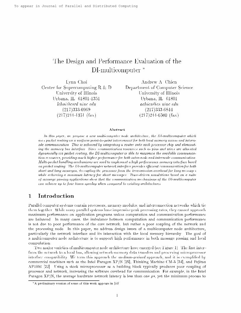
process communication delay is over 15 �s. Such high communication delay con�nes the machine tothe exploitation of medium-grained parallelism, limiting the application scope and scalability of thesemachines. In addition, medium-grained machines exhibit other critical problems. First, sharing a busbetween local memory access and internode communication limits the available bandwidth for both ac-tivities. Second, the medium-grained machines typically transfer incoming messages into the memoryand then to the processor, producing long response times for short messages.Medium−grained Node Fine−grained Node
MEMORY
Router
MEMORY
P +Cache
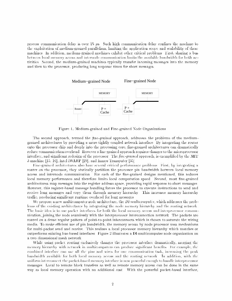
P +CacheFigure 1: Medium-grained and Fine-grained Node Organizations.The second approach, termed the �ne-grained approach, addresses the problems of the medium-grained architectures by providing a more tightly coupled network interface. By integrating the routeronto the processor chip and deeply into the processing core, �ne-grained architectures can dramaticallyreduce communicationoverhead. However a �ne-grained approach requires changes to the microprocessorinterface, and signi�cant redesign of the processor. The �ne-grained approach, is exempli�ed by the MITJ-machine [15, 16], Intel iWARP [29], and Inmos Transputer [35].Fine-grained architectures also have several critical performance problems. First, by integrating arouter on the processor, they statically partition the processor pin bandwidth between local memoryaccess and internode communication. For each of the �ne-grained designs mentioned, this reduceslocal memory performance and therefore limits local computation speed. Second, most �ne-grainedarchitectures map messages into the register address space, providing rapid response to short messages.However, this register-based message handling forces the processor to execute instructions to send andreceive long messages and copy them through memory hierarchy. This increases memory hierarchytra�c, producing signi�cant runtime overhead for long messages.We propose a new multicomputer node architecture, the DI-multicomputer, which addresses the prob-lems of the existing architectures by integrating the node memory hierarchy and the routing network.The basic idea is to use packet interfaces for both the local memory access and interprocessor commu-nication, joining the node seamlessly with the interprocessor interconnection network. The packets arerouted on a dense regular pattern of point-to-point interconnects which is chosen to saturate the wiringmedia. To make e�cient use of pin bandwidth, the memory access by node processor uses mechanismsfor multi-packet send and receive. This realizes a local processor memory hierarchy which matches oroutperforms existing bus-based interfaces. Figure 2 illustrates a DI-multicomputer node organization ona two dimensional mesh network.While using packet routing exclusively changes the processor interface dramatically, merging thememory hierarchy with network in multicomputers can produce signi�cant bene�ts. For example, thecombined interface can use all the pins and wires for one communication task, increasing the peakbandwidth available for both local memory access and the routing network. In addition, with theuniform interconnect the packet-based memory interface is now powerful enough to handle interprocessormessages. Local to remote block transfers as well as remote memory access can be done in the sameway as local memory operation with no additional cost. With the powerful packet-based interface,2
DI−micro Node architecture
NodeBoundary
M M M M M M
M M MM M M
M M MM P +Cache
P +CacheFigure 2: A DI-multicomputer node.the DI-multicomputer network interface directs di�erent types of messages to di�erent levels of thememory hierarchy under software control, achieving both low-latency response for short messages andhigh-bandwidth transfers for long messages.In this paper, we describe the design of the DI-multicomputer, an architecture based on dynamic in-terconnection and compare its performance to several existing multicomputer architectures. To evaluatethe memory hierarchy performance of a node based on DI, we compare the bus interface of an existingmicroprocessor to the packet-based memory interface of the DI-multicomputer processor. Also, we eval-uate the communication performance of the DI-multicomputer by running a trace driven simulation onexisting message passing applications. Our results indicate that a node architecture based on dynamicinterconnection has signi�cant performance advantages in the areas of processor memory bandwidth andboth short and long message passing.Overview The rest of paper is organized as follows. In Section 2, we discuss some critical performancelimitations of existing architectures that motivate the design of a new communication architecture. Sec-tion 3 introduces the basic ideas behind the DI-multicomputer and describes the register �le architectureof its processor. Section 4 and 5 present the novel mechanisms which allow the DI-multicomputer tosupport both a high-performance local memory hierarchy and low-latency interprocessor communica-tion. In Section 6, we compare the performance of a DI-multicomputer node to that of traditionalbus-based nodes, showing that the DI-multicomputer attains much higher performance in both thememory hierarchy and message-passing operations. Section 7 discusses the key implementation issuesfor a DI-multicomputer node. Finally, Section 8 and 9 discuss related work and summarize the researchresults.2 Motivation for A New Communication StructureThe relentless increase in computing performance of microprocessors continues to raise their input/outputrequirements. Latency hiding and avoidance techniques such as prefetching and multithreading furtherincrease input/output requirements, making communication resources such as pins and wires a per-formance critical bottleneck. As a result, the communication structure which interconnects hardwaremodules has an increasingly signi�cant contribution to overall system performance. In this section, wediscuss two critical problems of traditional interconnection structures and present dynamic interconnec-tion as an alternative structure for future multicomputers.3
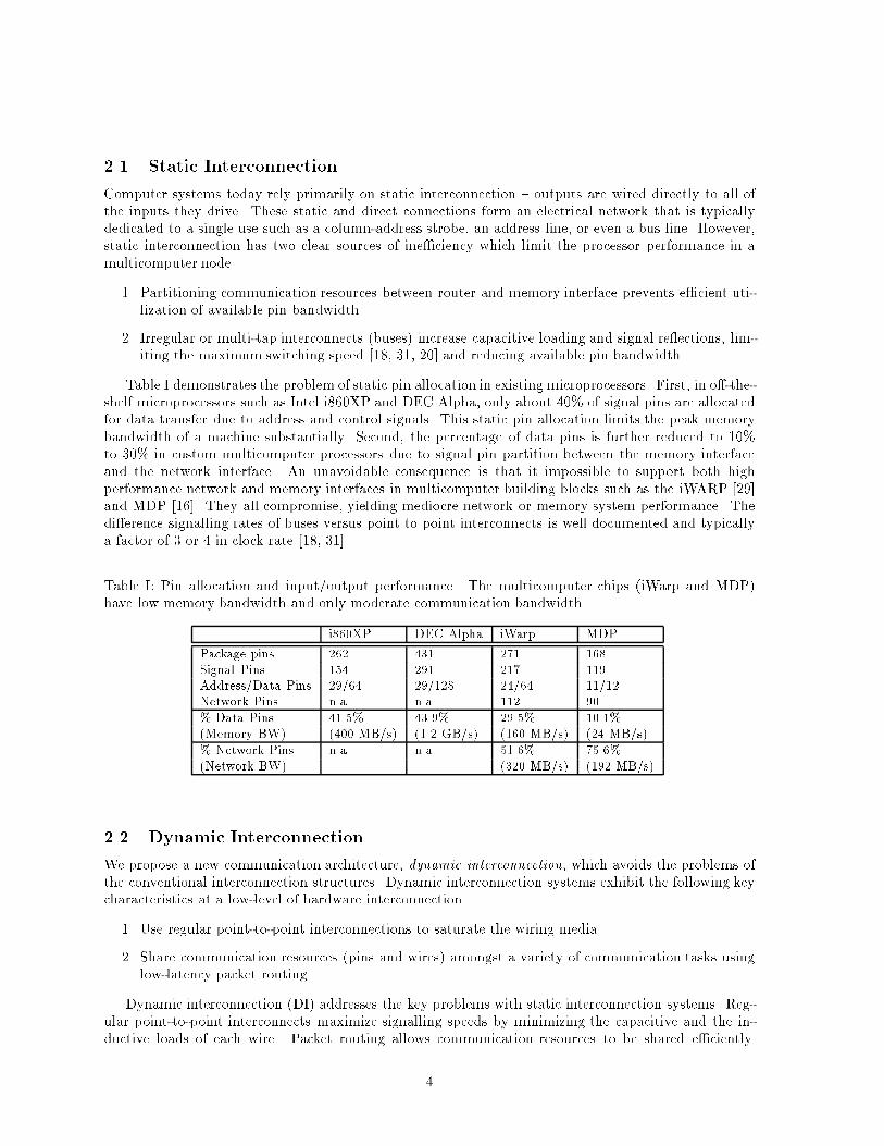
2.1 Static InterconnectionComputer systems today rely primarily on static interconnection { outputs are wired directly to all ofthe inputs they drive. These static and direct connections form an electrical network that is typicallydedicated to a single use such as a column-address strobe, an address line, or even a bus line. However,static interconnection has two clear sources of ine�ciency which limit the processor performance in amulticomputer node.1. Partitioning communication resources between router and memory interface prevents e�cient uti-lization of available pin bandwidth.2. Irregular or multi-tap interconnects (buses) increase capacitive loading and signal re ections, lim-iting the maximum switching speed [18, 31, 20] and reducing available pin bandwidth.Table I demonstrates the problem of static pin allocation in existing microprocessors. First, in o�-the-shelf microprocessors such as Intel i860XP and DEC Alpha, only about 40% of signal pins are allocatedfor data transfer due to address and control signals. This static pin allocation limits the peak memorybandwidth of a machine substantially. Second, the percentage of data pins is further reduced to 10%to 30% in custom multicomputer processors due to signal pin partition between the memory interfaceand the network interface. An unavoidable consequence is that it impossible to support both highperformance network and memory interfaces in multicomputer building blocks such as the iWARP [29]and MDP [16]. They all compromise, yielding mediocre network or memory system performance. Thedi�erence signalling rates of buses versus point to point interconnects is well documented and typicallya factor of 3 or 4 in clock rate [18, 31].Table I: Pin allocation and input/output performance. The multicomputer chips (iWarp and MDP)have low memory bandwidth and only moderate communication bandwidth.i860XP DEC Alpha iWarp MDPPackage pins 262 431 271 168Signal Pins 154 291 217 119Address/Data Pins 29/64 29/128 24/64 11/12Network Pins n.a. n.a. 112 90% Data Pins 41.5% 43.9% 29.5% 10.1%(Memory BW) (400 MB/s) (1.2 GB/s) (160 MB/s) (24 MB/s)% Network Pins n.a. n.a. 51.6% 75.6%(Network BW) (320 MB/s) (192 MB/s)2.2 Dynamic InterconnectionWe propose a new communication architecture, dynamic interconnection, which avoids the problems ofthe conventional interconnection structures. Dynamic interconnection systems exhibit the following keycharacteristics at a low-level of hardware interconnection.1. Use regular point-to-point interconnections to saturate the wiring media.2. Share communication resources (pins and wires) amongst a variety of communication tasks usinglow-latency packet routing.Dynamic interconnection (DI) addresses the key problems with static interconnection systems. Reg-ular point-to-point interconnects maximize signalling speeds by minimizing the capacitive and the in-ductive loads of each wire. Packet routing allows communication resources to be shared e�ciently.4
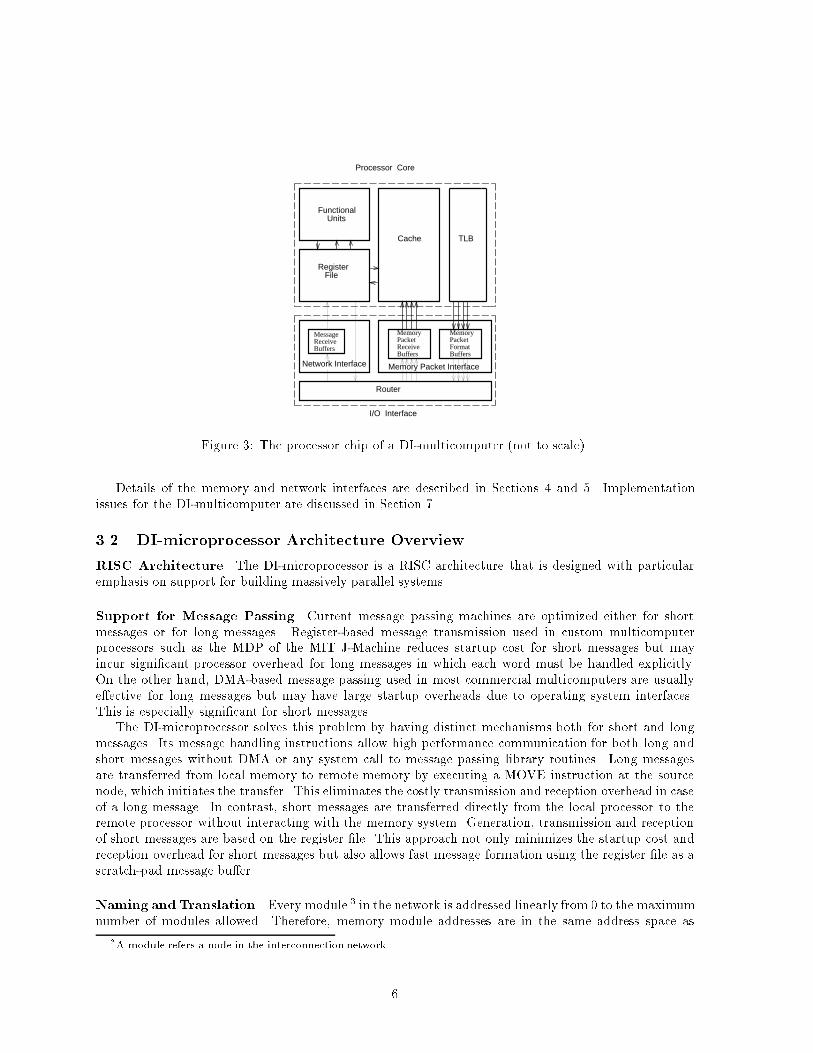
Advances in packet routers allow them to attain channel utilizations in excess of 90% [14] and extremelylow latency [33]. These characteristics enable dynamic interconnection systems to achieve comparablecommunication latencies and much higher bandwidth.Dynamic interconnection systems have two major advantages. First, pooling communication re-sources among several tasks eliminates the resource idle time in the static interconnection system. Thisallows the entire bandwidth to be focused on either the memory or network interface, giving both muchhigher peak performance. Second, though using regular, point-to-point interconnection requires commu-nications to be routed dynamically, incurring additional delay, dynamic interconnection not only allowsthe wiring media to be saturated, maximizing the wire bisection, it also allows the wires to be switchedat maximum speed, maximizing the bandwidth of each wire. Together, these two features maximize thecommunication capacity of the system.3 A Multicomputer Node Architecture based on Dynamic In-terconnectionUsing dynamic interconnection requires modi�cation to the input/output interface of each multicomputernode. A DI-multicomputer node consists of three elements: a processor, memory units, and routers.However, rather than connecting the elements via a shared node bus, each element is embedded ina low-latency packet routing network, requiring a small router1 per element. In addition to messagepassing, all local memory operations such as cache re�lls are achieved by sending and receiving packets(see Figure 7).3.1 Design ConceptsThe DI-multicomputer processor, called the DI-microprocessor, is a RISC processor extended with anetwork interface, router and a number of memory packet send and receive bu�ers, replacing the bus-based memory interface. The DI-microprocessor uses a DEC Alpha microprocessor architecture [19] asits base RISC processor. The DI-microprocessor instruction set architecture uses a subset of the DECAlpha microprocessor instruction set augmented with instruction support for message passing, addresstranslation and synchronization. 2The high-level organization of the DI-microprocessor is shown in Figure 3. The specialized memory-packet send and receive bu�ers allow the memory interface to handle multiple memory packets simultane-ously, enabling the full utilization of the processor chip bandwidth. The network interface distinguishesmemory packets with communication packets and is also responsible for ow control between router andboth memory and network interfaces.� Memory interface: Multi-packet Handling To build a high performance memory hierarchy,it is critical to utilize all the pin bandwidth at the processor chip boundary. The multi-packethandling of the DI-microprocessor's memory interface enables e�cient use of the pin bandwidthwith a simple hardware.� Network Interface: DistinctMechanisms for Short and LongMessagesThe DI-multicomputer'sparallel interconnect allows messages to be routed directly to an appropriate level of the memoryhierarchy, supporting high performance for both short and long messages. In particular, short mes-sages are routed directly onto the processor chip, allowing them to be handled with low latency.Long messages are routed directly from local memory to remote memory under software control.1As a variety of designs have shown [17], a router need not require a large amount of hardware. For example, the threedimensional router used in the J-machine [15] requires only 29,000 transistors.2The instruction set design and the memory and message packet formats of the DI-microprocessor are described inAppendix A and B. 5
Functional Units
Register File
Cache TLB
MemoryPacketFormatBuffers
MemoryPacketReceive Buffers
MessageReceiveBuffers
Router
Processor Core
Network Interface Memory Packet Interface
I/O InterfaceFigure 3: The processor chip of a DI-multicomputer (not to scale).Details of the memory and network interfaces are described in Sections 4 and 5. Implementationissues for the DI-multicomputer are discussed in Section 7.3.2 DI-microprocessor Architecture OverviewRISC Architecture The DI-microprocessor is a RISC architecture that is designed with particularemphasis on support for building massively parallel systems.Support for Message Passing Current message passing machines are optimized either for shortmessages or for long messages. Register-based message transmission used in custom multicomputerprocessors such as the MDP of the MIT J-Machine reduces startup cost for short messages but mayincur signi�cant processor overhead for long messages in which each word must be handled explicitly.On the other hand, DMA-based message passing used in most commercial multicomputers are usuallye�ective for long messages but may have large startup overheads due to operating system interfaces.This is especially signi�cant for short messages.The DI-microprocessor solves this problem by having distinct mechanisms both for short and longmessages. Its message handling instructions allow high performance communication for both long andshort messages without DMA or any system call to message passing library routines. Long messagesare transferred from local memory to remote memory by executing a MOVE instruction at the sourcenode, which initiates the transfer. This eliminates the costly transmission and reception overhead in caseof a long message. In contrast, short messages are transferred directly from the local processor to theremote processor without interacting with the memory system. Generation, transmission and receptionof short messages are based on the register �le. This approach not only minimizes the startup cost andreception overhead for short messages but also allows fast message formation using the register �le as ascratch-pad message bu�er.Naming and Translation Every module 3 in the network is addressed linearly from 0 to the maximumnumber of modules allowed. Therefore, memory module addresses are in the same address space as3A module refers a node in the interconnection network. 6
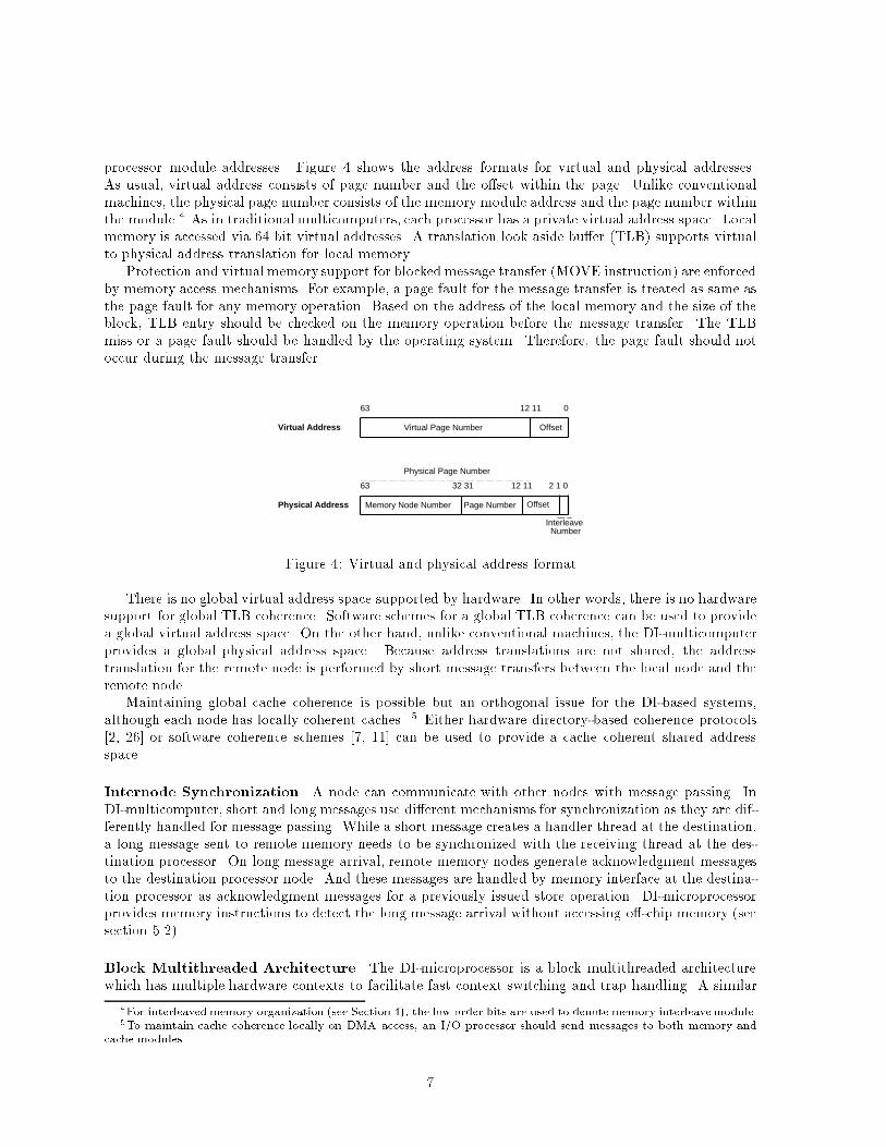
processor module addresses. Figure 4 shows the address formats for virtual and physical addresses.As usual, virtual address consists of page number and the o�set within the page. Unlike conventionalmachines, the physical page number consists of the memory module address and the page number withinthe module.4 As in traditional multicomputers, each processor has a private virtual address space. Localmemory is accessed via 64 bit virtual addresses. A translation look aside bu�er (TLB) supports virtualto physical address translation for local memory.Protection and virtual memory support for blocked message transfer (MOVE instruction) are enforcedby memory access mechanisms. For example, a page fault for the message transfer is treated as same asthe page fault for any memory operation. Based on the address of the local memory and the size of theblock, TLB entry should be checked on the memory operation before the message transfer. The TLBmiss or a page fault should be handled by the operating system. Therefore, the page fault should notoccur during the message transfer.Virtual Page Number
Memory Node Number Page Number Offset
Physical Page Number
Offset
63 12 11 0
63
Virtual Address
Physical Address
Interleave Number
32 31 12 11 2 1 0Figure 4: Virtual and physical address formatThere is no global virtual address space supported by hardware. In other words, there is no hardwaresupport for global TLB coherence. Software schemes for a global TLB coherence can be used to providea global virtual address space. On the other hand, unlike conventional machines, the DI-multicomputerprovides a global physical address space. Because address translations are not shared, the addresstranslation for the remote node is performed by short message transfers between the local node and theremote node.Maintaining global cache coherence is possible but an orthogonal issue for the DI-based systems,although each node has locally coherent caches. 5 Either hardware directory-based coherence protocols[2, 26] or software coherence schemes [7, 11] can be used to provide a cache coherent shared addressspace.Internode Synchronization A node can communicate with other nodes with message passing. InDI-multicomputer, short and long messages use di�erent mechanisms for synchronization as they are dif-ferently handled for message passing. While a short message creates a handler thread at the destination,a long message sent to remote memory needs to be synchronized with the receiving thread at the des-tination processor. On long message arrival, remote memory nodes generate acknowledgment messagesto the destination processor node. And these messages are handled by memory interface at the destina-tion processor as acknowledgment messages for a previously issued store operation. DI-microprocessorprovides memory instructions to detect the long message arrival without accessing o�-chip memory (seesection 5.2).Block Multithreaded Architecture The DI-microprocessor is a block multithreaded architecturewhich has multiple hardware contexts to facilitate fast context switching and trap handling. A similar4For interleavedmemory organization (see Section 4), the low order bits are used to denote memory interleavemodule.5To maintain cache coherence locally on DMA access, an I/O processor should send messages to both memory andcache modules. 7
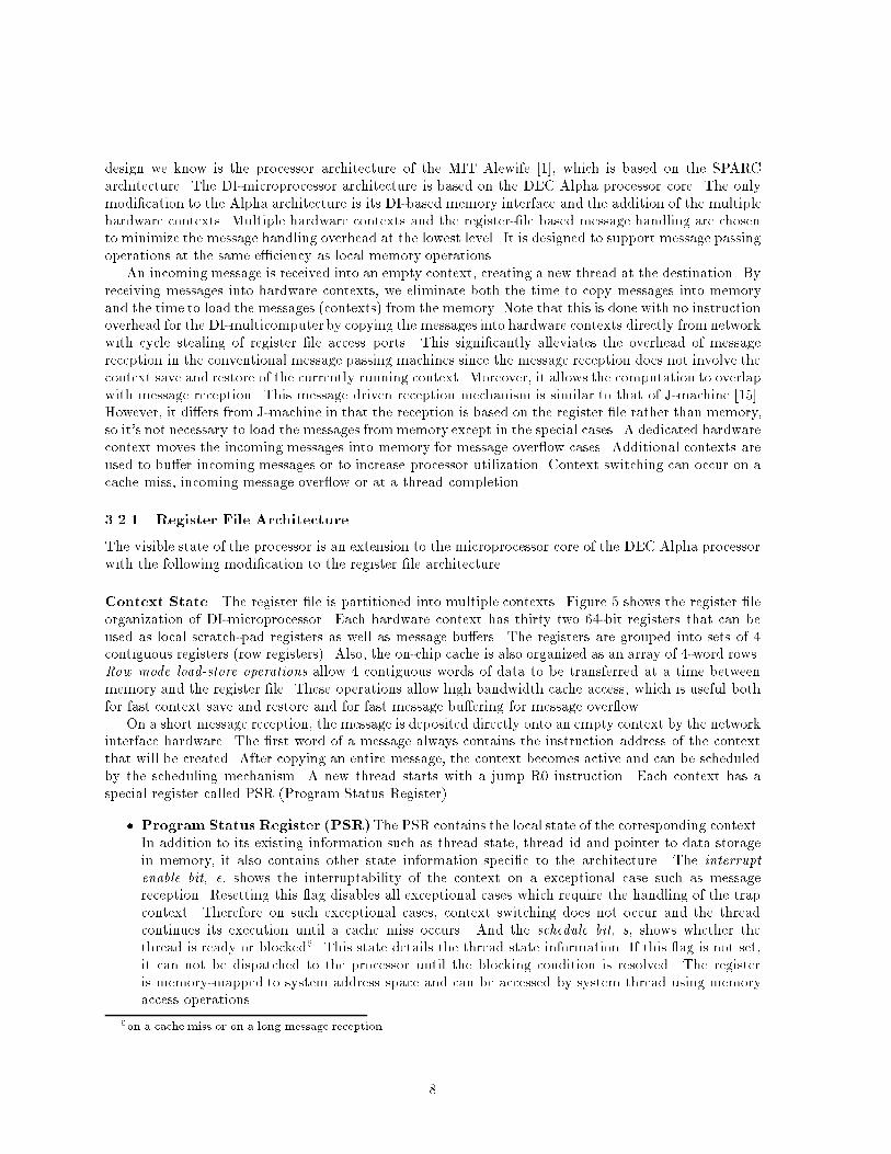
design we know is the processor architecture of the MIT Alewife [1], which is based on the SPARCarchitecture. The DI-microprocessor architecture is based on the DEC Alpha processor core. The onlymodi�cation to the Alpha architecture is its DI-based memory interface and the addition of the multiplehardware contexts. Multiple hardware contexts and the register-�le based message handling are chosento minimize the message handling overhead at the lowest level. It is designed to support message passingoperations at the same e�ciency as local memory operations.An incoming message is received into an empty context, creating a new thread at the destination. Byreceiving messages into hardware contexts, we eliminate both the time to copy messages into memoryand the time to load the messages (contexts) from the memory. Note that this is done with no instructionoverhead for the DI-multicomputer by copying the messages into hardware contexts directly from networkwith cycle stealing of register �le access ports. This signi�cantly alleviates the overhead of messagereception in the conventional message passing machines since the message reception does not involve thecontext save and restore of the currently running context. Moreover, it allows the computation to overlapwith message reception. This message driven reception mechanism is similar to that of J-machine [15].However, it di�ers from J-machine in that the reception is based on the register �le rather than memory,so it's not necessary to load the messages frommemory except in the special cases. A dedicated hardwarecontext moves the incoming messages into memory for message over ow cases. Additional contexts areused to bu�er incoming messages or to increase processor utilization. Context switching can occur on acache miss, incoming message over ow or at a thread completion.3.2.1 Register File ArchitectureThe visible state of the processor is an extension to the microprocessor core of the DEC Alpha processorwith the following modi�cation to the register �le architecture.Context State The register �le is partitioned into multiple contexts. Figure 5 shows the register �leorganization of DI-microprocessor. Each hardware context has thirty two 64-bit registers that can beused as local scratch-pad registers as well as message bu�ers. The registers are grouped into sets of 4contiguous registers (row registers). Also, the on-chip cache is also organized as an array of 4-word rows.Row mode load-store operations allow 4 contiguous words of data to be transferred at a time betweenmemory and the register �le. These operations allow high bandwidth cache access, which is useful bothfor fast context save and restore and for fast message bu�ering for message over ow.On a short message reception, the message is deposited directly onto an empty context by the networkinterface hardware. The �rst word of a message always contains the instruction address of the contextthat will be created. After copying an entire message, the context becomes active and can be scheduledby the scheduling mechanism. A new thread starts with a jump R0 instruction. Each context has aspecial register called PSR (Program Status Register).� Program Status Register (PSR)The PSR contains the local state of the corresponding context.In addition to its existing information such as thread state, thread id and pointer to data storagein memory, it also contains other state information speci�c to the architecture. The interruptenable bit, e, shows the interruptability of the context on a exceptional case such as messagereception. Resetting this ag disables all exceptional cases which require the handling of the trapcontext. Therefore on such exceptional cases, context switching does not occur and the threadcontinues its execution until a cache miss occurs. And the schedule bit, s, shows whether thethread is ready or blocked6. This state details the thread state information. If this ag is not set,it can not be dispatched to the processor until the blocking condition is resolved. The registeris memory-mapped to system address space and can be accessed by system thread using memoryaccess operations.6on a cache miss or on a long message reception 8
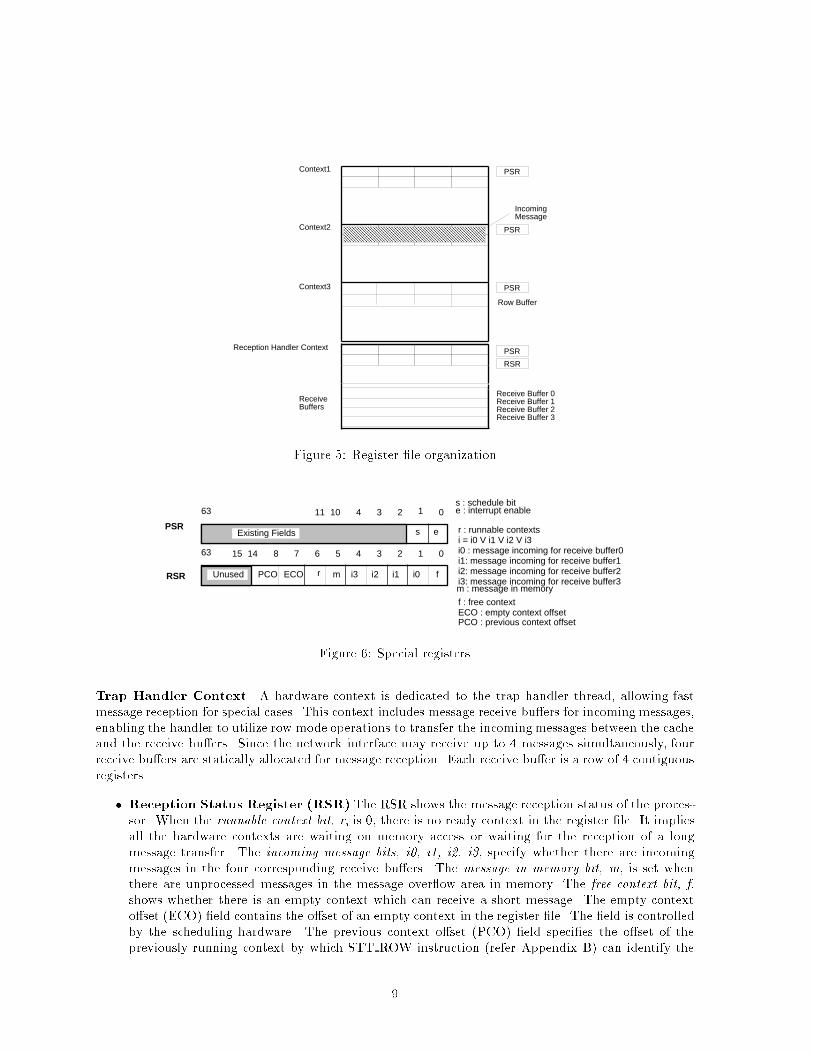
IncomingMessage
Context1
Context2
Reception Handler Context
Receive Buffers
Context3
Row Buffer
Receive Buffer 0Receive Buffer 1Receive Buffer 2Receive Buffer 3
PSR
PSR
PSR
PSR
RSRFigure 5: Register �le organization63 0
63 0
r
r : runnable contexts
s
i0i1i2i3 f
i0 : message incoming for receive buffer0i1: message incoming for receive buffer1i2: message incoming for receive buffer2i3: message incoming for receive buffer3
f : free contextECO : empty context offset
ECO
PSR
m
i = i0 V i1 V i2 V i3
RSR
12341011
123456781415
Unused
Existing Fields
m : message in memory
s : schedule bite : interrupt enable
e
PCO
PCO : previous context offsetFigure 6: Special registersTrap Handler Context A hardware context is dedicated to the trap handler thread, allowing fastmessage reception for special cases. This context includes message receive bu�ers for incoming messages,enabling the handler to utilize row mode operations to transfer the incomingmessages between the cacheand the receive bu�ers. Since the network interface may receive up to 4 messages simultaneously, fourreceive bu�ers are statically allocated for message reception. Each receive bu�er is a row of 4 contiguousregisters.� Reception Status Register (RSR) The RSR shows the message reception status of the proces-sor. When the runnable context bit, r, is 0, there is no ready context in the register �le. It impliesall the hardware contexts are waiting on memory access or waiting for the reception of a longmessage transfer. The incoming message bits, i0, i1, i2, i3, specify whether there are incomingmessages in the four corresponding receive bu�ers. The message in memory bit, m, is set whenthere are unprocessed messages in the message over ow area in memory. The free context bit, f,shows whether there is an empty context which can receive a short message. The empty contexto�set (ECO) �eld contains the o�set of an empty context in the register �le. The �eld is controlledby the scheduling hardware. The previous context o�set (PCO) �eld speci�es the o�set of thepreviously running context by which STT ROW instruction (refer Appendix B) can identify the9
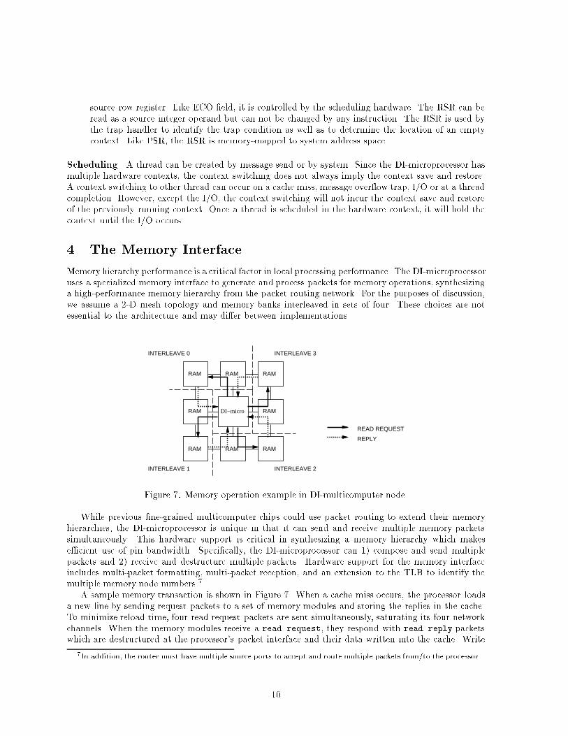
source row register. Like ECO �eld, it is controlled by the scheduling hardware. The RSR can beread as a source integer operand but can not be changed by any instruction. The RSR is used bythe trap handler to identify the trap condition as well as to determine the location of an emptycontext. Like PSR, the RSR is memory-mapped to system address space.Scheduling A thread can be created by message send or by system. Since the DI-microprocessor hasmultiple hardware contexts, the context switching does not always imply the context save and restore.A context switching to other thread can occur on a cache miss, message over ow trap, I/O or at a threadcompletion. However, except the I/O, the context switching will not incur the context save and restoreof the previously running context. Once a thread is scheduled in the hardware context, it will hold thecontext until the I/O occurs.4 The Memory InterfaceMemory hierarchy performance is a critical factor in local processing performance. The DI-microprocessoruses a specialized memory interface to generate and process packets for memory operations, synthesizinga high-performance memory hierarchy from the packet routing network. For the purposes of discussion,we assume a 2-D mesh topology and memory banks interleaved in sets of four. These choices are notessential to the architecture and may di�er between implementations.DI−micro
RAM RAM RAM
RAM RAM
RAM RAM RAM
INTERLEAVE 0
INTERLEAVE 1 INTERLEAVE 2
INTERLEAVE 3
READ REQUEST
REPLYFigure 7: Memory operation example in DI-multicomputer node.While previous �ne-grained multicomputer chips could use packet routing to extend their memoryhierarchies, the DI-microprocessor is unique in that it can send and receive multiple memory packetssimultaneously. This hardware support is critical in synthesizing a memory hierarchy which makese�cient use of pin bandwidth. Speci�cally, the DI-microprocessor can 1) compose and send multiplepackets and 2) receive and destructure multiple packets. Hardware support for the memory interfaceincludes multi-packet formatting, multi-packet reception, and an extension to the TLB to identify themultiple memory node numbers.7A sample memory transaction is shown in Figure 7. When a cache miss occurs, the processor loadsa new line by sending request packets to a set of memory modules and storing the replies in the cache.To minimize reload time, four read request packets are sent simultaneously, saturating its four networkchannels. When the memory modules receive a read request, they respond with read reply packetswhich are destructured at the processor's packet interface and their data written into the cache. Write7In addition, the router must have multiple source ports to accept and route multiple packets from/to the processor.10
operations are performed in a simlar fashion, with all write requests being acknowledged by a writereply so the processor can detect write completion.VirtualPage #
NodeAddr0
NodeAddr1
NodeAddr2
Node Addr3
PhysPage#
NodeAddr0
NodeAddr1
NodeAddr2
NodeAddr3
TypeTagOffsetSize
PhysAddr
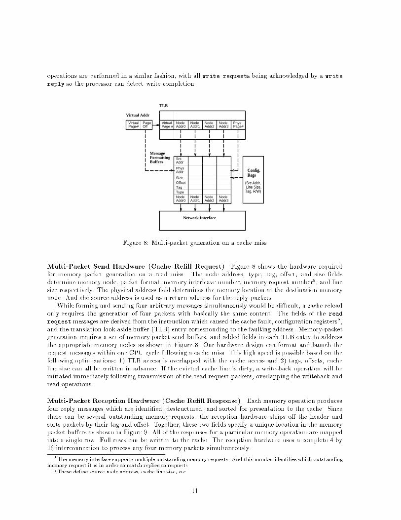
TLB
MessageFormattingBuffers
Config.Regs
(Src Addr, Line Size,Tag, R/W)
SrcAddr
VirtualPage#
PageOff
Virtual Addr
Network InterfaceFigure 8: Multi-packet generation on a cache missMulti-Packet Send Hardware (Cache Re�ll Request) Figure 8 shows the hardware requiredfor memory packet generation on a read miss. The node address, type, tag, o�set, and size �eldsdetermine memory node, packet format, memory interleave number, memory request number8, and linesize respectively. The physical address �eld determines the memory location at the destination memorynode. And the source address is used as a return address for the reply packets.While forming and sending four arbitrary messages simultaneously would be di�cult, a cache reloadonly requires the generation of four packets with basically the same content. The �elds of the readrequestmessages are derived from the instruction which caused the cache fault, con�guration registers9,and the translation look aside bu�er (TLB) entry corresponding to the faulting address. Memory-packetgeneration requires a set of memory packet send bu�ers, and added �elds in each TLB entry to addressthe appropriate memory nodes as shown in Figure 8. Our hardware design can format and launch therequest messages within one CPU cycle following a cache miss. This high speed is possible based on thefollowing optimizations: 1) TLB access is overlapped with the cache access and 2) tags, o�sets, cacheline size can all be written in advance. If the evicted cache line is dirty, a write-back operation will beinitiated immediately following transmission of the read request packets, overlapping the writeback andread operations.Multi-Packet Reception Hardware (Cache Re�ll Response) Each memory operation producesfour reply messages which are identi�ed, destructured, and sorted for presentation to the cache. Sincethere can be several outstanding memory requests; the reception hardware strips o� the header andsorts packets by their tag and o�set. Together, these two �elds specify a unique location in the memorypacket bu�ers as shown in Figure 9. All of the responses for a particular memory operation are mappedinto a single row. Full rows can be written to the cache. The reception hardware uses a complete 4 by16 interconnection to process any four memory packets simultaneously.8The memory interface supports multiple outstandingmemory requests. And this number identi�es which outstandingmemory request it is in order to match replies to requests.9These de�ne source node address, cache line size, etc. 11
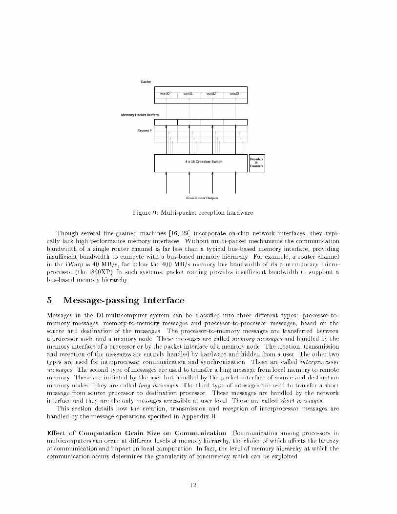
Cache
Memory Packet Buffers
4 x 16 Crossbar Switch
word0 word1 word2 word3
Decoders &Counters
Request #
From Router OutputsFigure 9: Multi-packet reception hardwareThough several �ne-grained machines [16, 29] incorporate on-chip network interfaces, they typi-cally lack high performance memory interfaces. Without multi-packet mechanisms the communicationbandwidth of a single router channel is far less than a typical bus-based memory interface, providinginsu�cient bandwidth to compete with a bus-based memory hierarchy. For example, a router channelin the iWarp is 40 MB/s, far below the 400 MB/s memory bus bandwidth of its contemporary micro-processor (the i860XP). In such systems, packet routing provides insu�cient bandwidth to supplant abus-based memory hierarchy.5 Message-passing InterfaceMessages in the DI-multicomputer system can be classi�ed into three di�erent types: processor-to-memory messages, memory-to-memory messages and processor-to-processor messages, based on thesource and destination of the messages. The processor-to-memory messages are transferred betweena processor node and a memory node. These messages are called memory messages and handled by thememory interface of a processor or by the packet interface of a memory node. The creation, transmissionand reception of the messages are entirely handled by hardware and hidden from a user. The other twotypes are used for interprocessor communication and synchronization. These are called interprocessormessages. The second type of messages are used to transfer a long message from local memory to remotememory. These are initiated by the user but handled by the packet interface of source and destinationmemory nodes. They are called long messages. The third type of messages are used to transfer a shortmessage from source processor to destination processor. These messages are handled by the networkinterface and they are the only messages accessible at user level. Those are called short messages.This section details how the creation, transmission and reception of interprocessor messages arehandled by the message operations speci�ed in Appendix B.E�ect of Computation Grain Size on Communication Communication among processors inmulticomputers can occur at di�erent levels of memory hierarchy, the choice of which a�ects the latencyof communication and impact on local computation. In fact, the level of memory hierarchy at which thecommunication occurs determines the granularity of concurrency which can be exploited.12
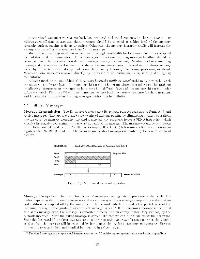
Fine-grained concurrency requires both low overhead and rapid response to short messages. Toachieve such e�cient interaction, short messages should be injected at a high level of the memoryhierarchy such as on-chip registers or caches. Otherwise, the memory hierarchy tra�c will increase thestartup cost as well as the response time for the messages.Medium and coarse-grained concurrency requires high bandwidth for long messages and overlappedcomputation and communication. To achieve a good performance, long message handling should bedecoupled from the processor, transferring messages directly into memory. Sending and receiving longmessages at the register level is inappropriate as it incurs transmission overhead and produces memoryhierarchy tra�c to move data up and down the memory hierarchy, increasing processing overhead.Moreover, long messages received directly by processor causes cache pollution, slowing the ongoingcomputation.Existing machines do not address this memory hierarchy tra�c overhead problem as they each attachthe network to only one level of the memory hierarchy. The DI-multicomputer addresses this problemby allowing interprocessor messages to be directed to di�erent levels of the memory hierarchy undersoftware control. Thus, the DI-multicomputer can achieve both low-latency response for short messagesand high-bandwidth transfers for long messages without cache pollution.5.1 Short MessagesMessage Transmission The DI-microprocessor uses its general purpose registers to form, send andreceive messages. This approach allows low overhead message passing by eliminating memory operationsmoving with the memory hierarchy. To send a message, the processor issues a SEND instruction whichspeci�es the register containing the �rst word and size of the message. The message should be contiguousin the local context as shown in Fig 10. For example, SEND R4, #5 transmits a �ve word message inregisters R4, R5, R6, R7 and R8. The message size of short messages is limited by the size of the localcontext.Register FileRow0
Row1
Row2
Row3
R0 R1
R15
a b c d
e
abcde
SEND R4, #5
Message ROUTER
; Send a Five Word Message in Registers 4, 5, 6, 7, 8Figure 10: Multi-send vs. send operationMessage Reception There are two types of messages coming into a processor node in the DI-multicomputer system: memory messages and short messages. On a message reception, the destinationnode address is stripped o� by the router, and the network interface decodes the packet type of theincoming message, distinguishing two di�erent message types.10 If the incoming message is identi�edas a short message type, the message is deposited directly into an empty context (register set) by thenetwork interface. After the entire message is copied, the context can be scheduled by the hardware.Since the �rst word of the short message contains the instruction address of a context, when the contextis scheduled, the message will be executed by jumping to that address. Memory messages are directedto memory receive bu�ers and handled by memory interface instead.10The detail message packet types and formats used in the DI-multicomputer systems are described in Appendix A.13
Trap Handling There are two exceptional cases which require special treatment. The �rst case occurswhen there are incoming messages but no empty context in the register �le (i0, i1, i2, or i3 = 1 and f =0). It requires the trap handler to copy the messages from the receive bu�ers to the message over owarea in memory. This is called a reception trap. The second case occurs when all the active threads areblocked and there is an available context which can hold an unprocessed message in memory (r = 0 andm = 1 and f = 1). Instead of idling the processor, the trap handler is invoked to load an unprocessedmessage from memory to an empty context in the register �le. This trap is called a reload trap. Theloaded message can be scheduled by the scheduling hardware as the ordinary messages arrived from thenetwork. These trap handling makes the message bu�ering for message over ow cases transparent tothe scheduling mechanism.Table II: Exception conditions and the corresponding state bits. The character X denotes the don't carecondition. i denotes i0 or i1 or i2 or i3state bits exception case descriptionf i m r0 1 X X no empty context during message reception1 X 1 0 no runnable contexts and unprocessed message in memoryThe network interface handles these exceptional cases through a fast software trap mechanism. Sincethis trap handler is resident at one of the hardware contexts, we can achieve fast trap handling in thecase of an exception, and the overhead of this software trap is just ushing the pipeline, which requiresonly a couple of CPU cycles.Reception Trap If there is no available context in the register �le, the incoming short message iscopied into the corresponding receive bu�er row by row by the network interface. After the �rst fourwords of the message is copied into the receive bu�er, the message incoming bit associated with thereceive bu�er is set by the interface. At the same time, the message reception trap occurs and contextswitches to the trap handler context. These messages are called over ow messages and copied intomessage over ow area in memory by the trap handler as shown in Figure 11. The trap handler checksthe status of message reception and stores the message into memory row by row. The trap handlerincludes the four receive bu�ers as part of its local context (row 4, 5, 6, 7) so that it can use ST ROWinstruction to bu�er the incoming messages in memory. The message incoming bit remains set if there isa remaining part of the message or more incoming messages. The trap handling continues until there isno more incoming message, which is indicated by the message incoming bits. Each time more than onemessages can be received by the trap handler. The message incoming bits are cleared by the networkinterface when there are no more incoming messages. At this time, the trap handling stops and contextswitches to the previously running context. The reception trap handler only needs to check the messageincoming bits to stop the trap handling. In addition to the message incoming bit, each receive bu�er hasan additional full-empty bit to provide ow control for reception. When the network interface copies arow of message from router into a receive bu�er, it sets the full-empty bit of the corresponding receivebu�er. And ST ROW operation from the receive bu�er clears this bit. In other words, reads or writesto these receive bu�ers has additional semantics for ow control. Read from empty receive bu�ers willblock until the bu�er is full, writes to full bu�ers will block until a read occurs.The Figure 11 illustrates the reception handling for the reception trap. In the example code shownin Figure 11, the handler manages the message over ow area as a circular bu�er11. The handler checksthe message incoming bit for each receive bu�er and copies the message if one is present.11The codes for boundary checking is not included in the example14
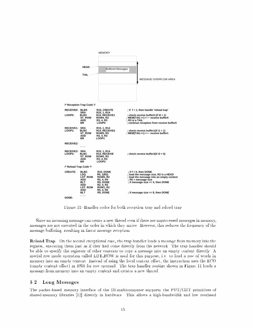
MESSAGE OVERFLOW AREA
MEMORY
Buffered Messages
TAIL
HEAD
/* Reception Trap Code */
RECEIVE0: BLBS R15, CREATE ; if f = 1, then handle ’reload trap’ SRA R15, 1, R14LOOP0: BLBC R14, RECEIVE1 ; check receive buffer0 (if i0 = 1) ST_ROW ROW4, R3 ; MEM[TAIL++] <−− receive buffer0 ADD R3, 4, R3 ; R3 is a TAIL BR LOOP0 ; continue reception from receive buffer0
RECEIVE1: SRA R15, 1, R14LOOP1: BLBC R14, RECEIVE2 ; check receive buffer1(if i1 = 1) ST_ROW ROW5, R3 ; MEM[TAIL++] <−− receive buffer1 ADD R3, 4, R3 BR LOOP1 RECEIVE2: . . . .
RECEIVE3: SRA R15, 1, R14 LOOP3: BLBC R14, RECEIVE ; check receive buffer3(if i3 = 0) ST_ROW ROW5, R3 ADD R3, 4, R3 BR LOOP3
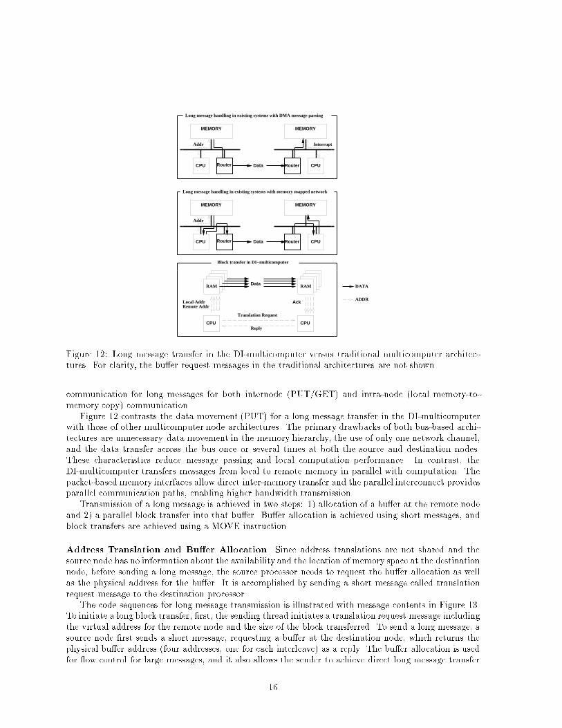
/* Reload Trap Code */ CREATE: BLBC R15, DONE ; if f = 0, then DONE LDQ R5, 1(R2) ; load the message size, R2 is a HEAD LDT_ROW ROW0, R2 ; load the message into an empty context ADD R5, 4, R5 ; R5 = message size BLT R5, DONE ; if message size <= 4, then DONE ADD R2, 4, R2 LDT_ROW ROW1, R2 ADD R5, 4, R5 BLT R5, DONE ; if message size <= 8, then DONE . . . .DONE:Figure 11: Handler codes for both reception trap and reload trapSince an incomingmessage can create a new thread even if there are unprocessed messages in memory,messages are not executed in the order in which they arrive. However, this reduces the frequency of themessage bu�ering, resulting in faster message reception.Reload Trap On the second exceptional case, the trap handler loads a message from memory into theregister, executing them just as if they had come directly from the network. The trap handler shouldbe able to specify the registers of other contexts to copy a message into an empty context directly. Aspecial row mode operation called LDT ROW is used for this purpose, i.e. to load a row of words inmemory into an empty context. Instead of using the local context o�set, the instruction uses the ECO(empty context o�set) in RSR for row operand. The trap handler routine shown in Figure 11 loads amessage from memory into an empty context and creates a new thread.5.2 Long MessagesThe packet-based memory interface of the DI-multicomputer supports the PUT/GET primitives ofshared-memory libraries [12] directly in hardware. This allows a high-bandwidth and low overhead15
MEMORY
CPU
MEMORY
CPU
CPU CPU
RAM RAM
Local AddrRemote Addr
Ack
Data
Translation Request
Reply
DATA
ADDR
Router RouterData
Addr
MEMORY
CPU
MEMORY
CPURouter RouterData
Addr
Long message handling in existing systems with DMA message passing
Interrupt
Long message handling in existing systems with memory mapped network
Block transfer in DI−multicomputer Figure 12: Long message transfer in the DI-multicomputer versus traditional multicomputer architec-tures. For clarity, the bu�er request messages in the traditional architectures are not shown.communication for long messages for both internode (PUT/GET) and intra-node (local memory-to-memory copy) communication.Figure 12 contrasts the data movement (PUT) for a long message transfer in the DI-multicomputerwith those of other multicomputer node architectures. The primary drawbacks of both bus-based archi-tectures are unnecessary data movement in the memory hierarchy, the use of only one network channel,and the data transfer across the bus once or several times at both the source and destination nodes.These characteristics reduce message passing and local computation performance. In contrast, theDI-multicomputer transfers messages from local to remote memory in parallel with computation. Thepacket-based memory interfaces allow direct inter-memory transfer and the parallel interconnect providesparallel communication paths, enabling higher bandwidth transmission.Transmission of a long message is achieved in two steps: 1) allocation of a bu�er at the remote nodeand 2) a parallel block transfer into that bu�er. Bu�er allocation is achieved using short messages, andblock transfers are achieved using a MOVE instruction.Address Translation and Bu�er Allocation Since address translations are not shared and thesource node has no information about the availability and the location of memory space at the destinationnode, before sending a long message, the source processor needs to request the bu�er allocation as wellas the physical address for the bu�er. It is accomplished by sending a short message called translationrequest message to the destination processor.The code sequences for long message transmission is illustrated with message contents in Figure 13.To initiate a long block transfer, �rst, the sending thread initiates a translation request message includingthe virtual address for the remote node and the size of the block transferred. To send a long message, asource node �rst sends a short message, requesting a bu�er at the destination node, which returns thephysical bu�er address (four addresses, one for each interleave) as a reply. The bu�er allocation is usedfor ow control for large messages, and it also allows the sender to achieve direct long message transfer16
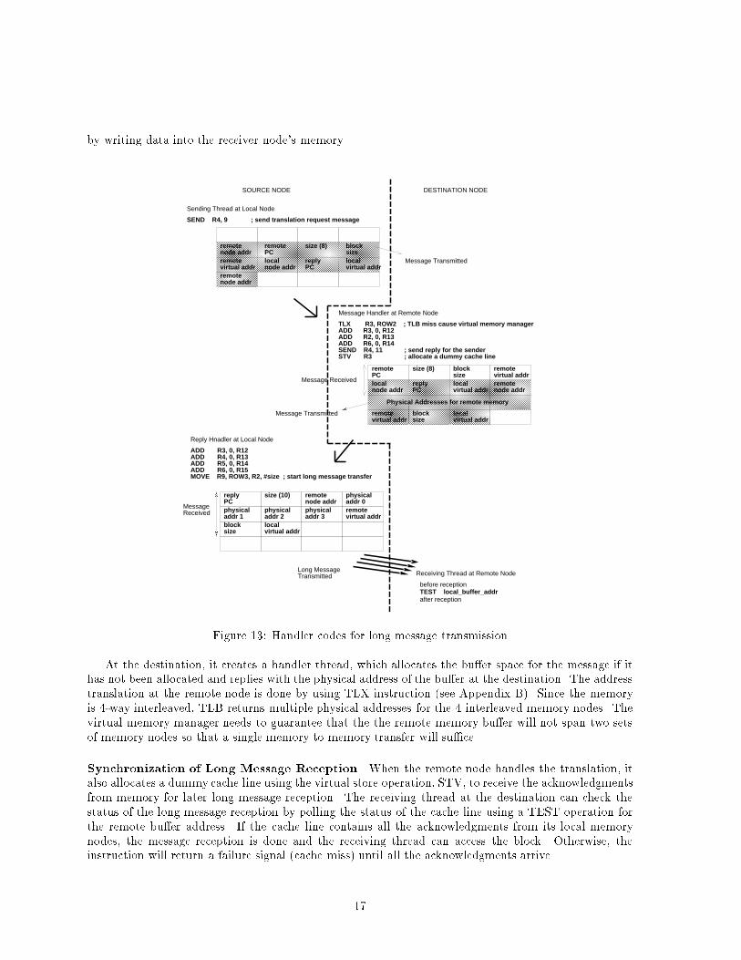
by writing data into the receiver node's memory.remote node addr
remotePC
size (8) blocksize
remotevirtual addr
localnode addr
replyPC
localvirtual addr
remote node addr
remotePC
size (8) block size
remotevirtual addr
localnode addr
replyPC
localvirtual addr
remote node addr
reply PC
size (10) remotenode addr
physicaladdr 0
physicaladdr 1
physicaladdr 2
physicaladdr 3
remotevirtual addr
block size
localvirtual addr
Message Transmitted
Message Received
Physical Addresses for remote memory
remotevirtual addr
blocksize
localvirtual addr
Message Transmitted
MessageReceived
SOURCE NODE DESTINATION NODE
Message Handler at Remote Node
Sending Thread at Local Node
Reply Hnadler at Local Node
Receiving Thread at Remote Node
before reception
after receptionTEST local_buffer_addr
Long MessageTransmitted
TLX R3, ROW2 ; TLB miss cause virtual memory manager ADD R3, 0, R12 ADD R2, 0, R13 ADD R6, 0, R14 SEND R4, 11 ; send reply for the sender STV R3 ; allocate a dummy cache line
SEND R4, 9 ; send translation request message
ADD R3, 0, R12ADD R4, 0, R13ADD R5, 0, R14ADD R6, 0, R15MOVE R9, ROW3, R2, #size ; start long message transfer
Figure 13: Handler codes for long message transmissionAt the destination, it creates a handler thread, which allocates the bu�er space for the message if ithas not been allocated and replies with the physical address of the bu�er at the destination. The addresstranslation at the remote node is done by using TLX instruction (see Appendix B). Since the memoryis 4-way interleaved, TLB returns multiple physical addresses for the 4 interleaved memory nodes. Thevirtual memory manager needs to guarantee that the the remote memory bu�er will not span two setsof memory nodes so that a single memory to memory transfer will su�ce.Synchronization of Long Message Reception When the remote node handles the translation, italso allocates a dummy cache line using the virtual store operation, STV, to receive the acknowledgmentsfrom memory for later long message reception. The receiving thread at the destination can check thestatus of the long message reception by polling the status of the cache line using a TEST operation forthe remote bu�er address. If the cache line contains all the acknowledgments from its local memorynodes, the message reception is done and the receiving thread can access the block. Otherwise, theinstruction will return a failure signal (cache miss) until all the acknowledgments arrive.17
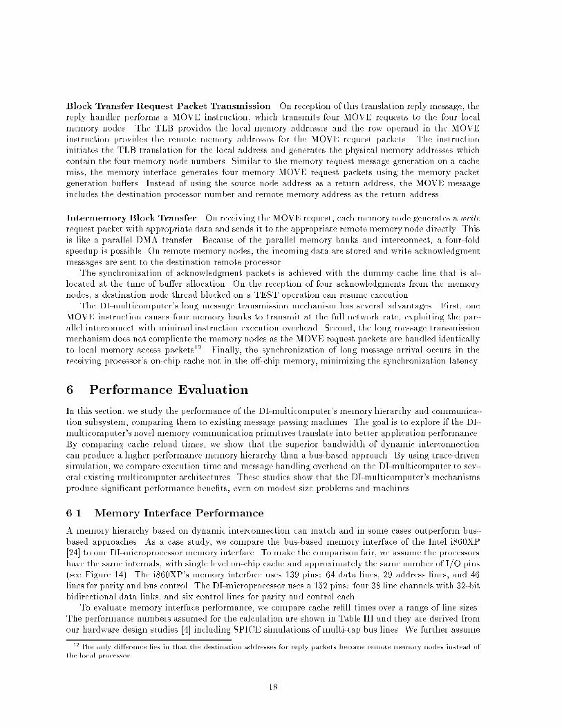
Block Transfer Request Packet Transmission On reception of this translation reply message, thereply handler performs a MOVE instruction, which transmits four MOVE requests to the four localmemory nodes. The TLB provides the local memory addresses and the row operand in the MOVEinstruction provides the remote memory addresses for the MOVE request packets. The instructioninitiates the TLB translation for the local address and generates the physical memory addresses whichcontain the four memory node numbers. Similar to the memory request message generation on a cachemiss, the memory interface generates four memory MOVE request packets using the memory packetgeneration bu�ers. Instead of using the source node address as a return address, the MOVE messageincludes the destination processor number and remote memory address as the return address.Intermemory Block Transfer On receiving the MOVE request, each memory node generates a writerequest packet with appropriate data and sends it to the appropriate remote memory node directly. Thisis like a parallel DMA transfer. Because of the parallel memory banks and interconnect, a four-foldspeedup is possible. On remote memory nodes, the incoming data are stored and write acknowledgmentmessages are sent to the destination remote processor.The synchronization of acknowledgment packets is achieved with the dummy cache line that is al-located at the time of bu�er allocation. On the reception of four acknowledgments from the memorynodes, a destination node thread blocked on a TEST operation can resume execution.The DI-multicomputer's long message transmission mechanism has several advantages. First, oneMOVE instruction causes four memory banks to transmit at the full network rate, exploiting the par-allel interconnect with minimal instruction execution overhead. Second, the long message transmissionmechanism does not complicate the memory nodes as the MOVE request packets are handled identicallyto local memory access packets12. Finally, the synchronization of long message arrival occurs in thereceiving processor's on-chip cache not in the o�-chip memory, minimizing the synchronization latency.6 Performance EvaluationIn this section, we study the performance of the DI-multicomputer's memory hierarchy and communica-tion subsystem, comparing them to existing message passing machines. The goal is to explore if the DI-multicomputer's novel memory communication primitives translate into better application performance.By comparing cache reload times, we show that the superior bandwidth of dynamic interconnectioncan produce a higher performance memory hierarchy than a bus-based approach. By using trace-drivensimulation, we compare execution time and message handling overhead on the DI-multicomputer to sev-eral existing multicomputer architectures. These studies show that the DI-multicomputer's mechanismsproduce signi�cant performance bene�ts, even on modest size problems and machines.6.1 Memory Interface PerformanceA memory hierarchy based on dynamic interconnection can match and in some cases outperform bus-based approaches. As a case study, we compare the bus-based memory interface of the Intel i860XP[24] to our DI-microprocessor memory interface. To make the comparison fair, we assume the processorshave the same internals, with single level on-chip cache and approximately the same number of I/O pins(see Figure 14). The i860XP's memory interface uses 139 pins: 64 data lines, 29 address lines, and 46lines for parity and bus control. The DI-microprocessor uses a 152 pins: four 38 line channels with 32-bitbidirectional data links, and six control lines for parity and control each.To evaluate memory interface performance, we compare cache re�ll times over a range of line sizes.The performance numbers assumed for the calculation are shown in Table III and they are derived fromour hardware design studies [4] including SPICE simulations of multi-tap bus lines. We further assume12The only di�erence lies in that the destination addresses for reply packets become remote memory nodes instead ofthe local processor. 18
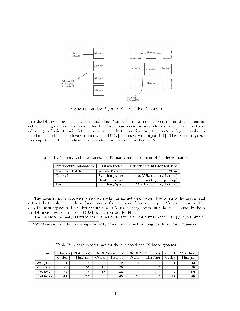
Inteli860XP
DI-micro
Address (29)+ Data (64)+ Control (46)
Memory
Memory
Memory
Memory
Memory
Memory
Memory
Memory
Data(32) + Control(6)Figure 14: Bus-based (i860XP) and DI-based systems.that the DI-microprocessor reloads its cache lines from its four nearest neighbors, minimizing the routingdelay. The higher network clock rate for the DI-microprocessor memory interface is due to the electricaladvantages of point-to-point interconnects over multi-tap bus lines [31, 18]. Router delay is based on anumber of published implementation studies [17, 32] and our own designs [4, 8]. The actions requiredto complete a cache line reload in each system are illustrated in Figure 15.Table III: Memory and interconnect performance numbers assumed for the evaluation.Architecture component Characteristics Performance number assumedMemory Module Access Time 20 nsNetwork Switching speed 200 MHz (5 ns cycle time)Routing Delay 20 ns (4 cycles per hop)Bus Switching Speed 50 MHz (20 ns cycle time)The memory node processes a request packet in six network cycles: two to strip the header andextract the the physical address, four to access the memory and form a reply. 13 Slower memories a�ectonly the memory access time. For example, with 60 ns memory access time the reload times for boththe DI-microprocessor and the i860XP would increase by 40 ns.The DI-based memory interface has a larger cache re�ll time for a small cache line (32 bytes) due to13O�-chip secondary caches can be implemented by SRAM memory modules in organization similar to Figure 14.Table IV: Cache reload times for the bus-based and DI-based systems.Line size DI-micro(32bit links) i860XP(64bit bus) i860XP(128bit bus) i860XP(256bit bus)Cycles Time(ns) Cycles Time(ns) Cycles Time(ns) Cycles Time(ns)32 bytes 29 145 6 120 4 80 3 6064 bytes 31 155 10 200 6 120 4 80128 bytes 35 175 18 360 10 200 6 120256 bytes 43 215 34 680 18 360 10 20019
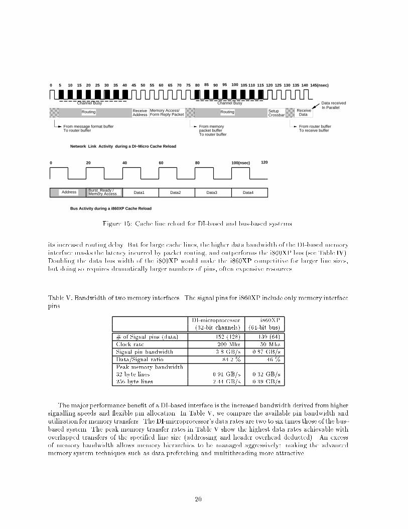
0 5 10 15 20 25 30 35 40 45 50 55 60 65 70 75 80
ReceiveAddress
Receive Data
From message format bufferTo router buffer
From memorypacket bufferTo router buffer
From router bufferTo receive buffer
85 90
Network Link Activity during a DI−Micro Cache Reload
0 20 40 60 80 100(nsec)
Data3Data1 Data2 Data4
120
Bus Activity during a i860XP Cache Reload
SetupCrossbar
Channel Busy
95
Data receivedIn Parallel
100
Memory Access/Form Reply Packet
Burst_Ready /Memory Access
Routing Routing
Address
105 110 115 120 125 130 135 140 145(nsec)
Channel Busy
Figure 15: Cache line reload for DI-based and bus-based systems.its increased routing delay. But for large cache lines, the higher data bandwidth of the DI-based memoryinterface masks the latency incurred by packet routing, and outperforms the i860XP bus (see Table IV).Doubling the data bus width of the i860XP would make the i860XP competitive for larger line sizes,but doing so requires dramatically larger numbers of pins, often expensive resources.Table V: Bandwidth of two memory interfaces. The signal pins for i860XP include only memory interfacepins. DI-microprocessor i860XP(32-bit channels) (64-bit bus)# of Signal pins (data) 152 (128) 139 (64)Clock rate 200 Mhz 50 MhzSignal pin bandwidth 3.8 GB/s 0.87 GB/sData/Signal ratio 84.2 % 46 %Peak memory bandwidth32 byte lines 0.91 GB/s 0.32 GB/s256 byte lines 2.44 GB/s 0.39 GB/sThe major performance bene�t of a DI-based interface is the increased bandwidth derived from highersignalling speeds and exible pin allocation. In Table V, we compare the available pin bandwidth andutilization for memory transfers. The DI-microprocessor's data rates are two to six times those of the bus-based system. The peak memory transfer rates in Table V show the highest data rates achievable withoverlapped transfers of the speci�ed line size (addressing and header overhead deducted). An excessof memory bandwidth allows memory hierarchies to be managed aggressively: making the advancedmemory system techniques such as data prefetching and multithreading more attractive.20
6.2 Parallel Computer PerformanceIn this section, we compare the message passing performance of the DI-multicomputer to the existing �ne-grained and coarse-grained multicomputer architectures. Trace-driven simulation using iPSC/2 traces[23] are used to address the following questions: (1) How much do the DI-multicomputer communicationprimitives speed up applications?, (2) How much performance improvement do the distinct mechanismsfor short and long messages give?, and (3) How do machine size ( number of processors) and applicationgranularity a�ect these tradeo�s? Our results show that by eliminating most of message handlingoverhead, the DI-multicomputer increases overall application performance by 7% to 485%. Distinctmessage passing mechanisms for short and long messages reduce memory hierarchy tra�c, improvingapplication performance by 5% to 77% compared to register based message handling. These results arguefor network interfaces that can direct messages either to the processor or to the memory as appropriate.Such distinct mechanisms allow a multicomputer node to give good performance for both coarse and�ne-grained applications. The DI-multicomputer's mechanisms also give more robust performance for avariety of system size and data sets.ExperimentationMethodology The trace driven simulation is chosen as an experimentationmethodsince it allows the simulation under real work load. Based on the machine dependent parameters suchas processor speed, network implementation and message passing cost, etc., the simulator can simu-late di�erent distributed memory machines and provides an experimentation framework that allows thecomparative evaluation of the DI-multicomputer to existing distributed memory machines.The performance impacts of the DI-multicomputer mechanisms depend on several factors such astarget machine architectures, communication characteristics of the applications, and the grain sizes ofthe data sets used. To validate this experimentation, traces are collected both for di�erent machine sizesand for di�erent data sets. Also, two existing target coarse-grained multicomputer architectures, InteliPSC/2 and Delta, as well as a �ne-grained multicomputer architecture similar to the J-Machine arecompared to the DI-multicomputer.The performance evaluation focuses on the performance comparison of communication architecturesof di�erent multicomputer organizations. Neither the implementation technology nor relative computa-tion speeds are considered for the comparison. To achieve this, we performed the simulation as follows.First, the message passing traces consist of message send/receive events and computation times in-between, all of which are directly measured by the application runs from the iPSC/2. By taking thecomputation time directly from the traces, all multicomputer architectures assume the same compu-tation performance. Therefore, the local memory system performance is also not considered for theperformance comparison. Second, to factor out the impact of di�erent implementation technology usedin di�erent multicomputer architectures, the simulations of DI-multicomputer architectures assume thesame network implementation (the same network bandwidth and the same routing latency per hop) asthe target machine architectures such as the iPSC/2 or Touchstone Delta.Simulation Model The execution time of parallel programs can be divided into computation time,communication time and idle time due to the synchronization. Even though the machine can supportideal communication performance (zero overhead and zero latency communication), there is an idle timedue to the synchronization among the multiple processes running on the di�erent nodes in the machine.In the simulation, the computation time is derived from the traces while the software and hardwarelatencies of the communicationand the idle time due to the synchronization are modeled by the simulator.In the current simulation, network load is assumed to be zero, i.e. no network tra�c is modeled.Applications The communication traces are collected from the following seven parallel applications(2 VLSI CAD applications, 4 numerical applications and 1 event-driven simulator). The applicationsare described in Table VI. The traces are derived from [23].21
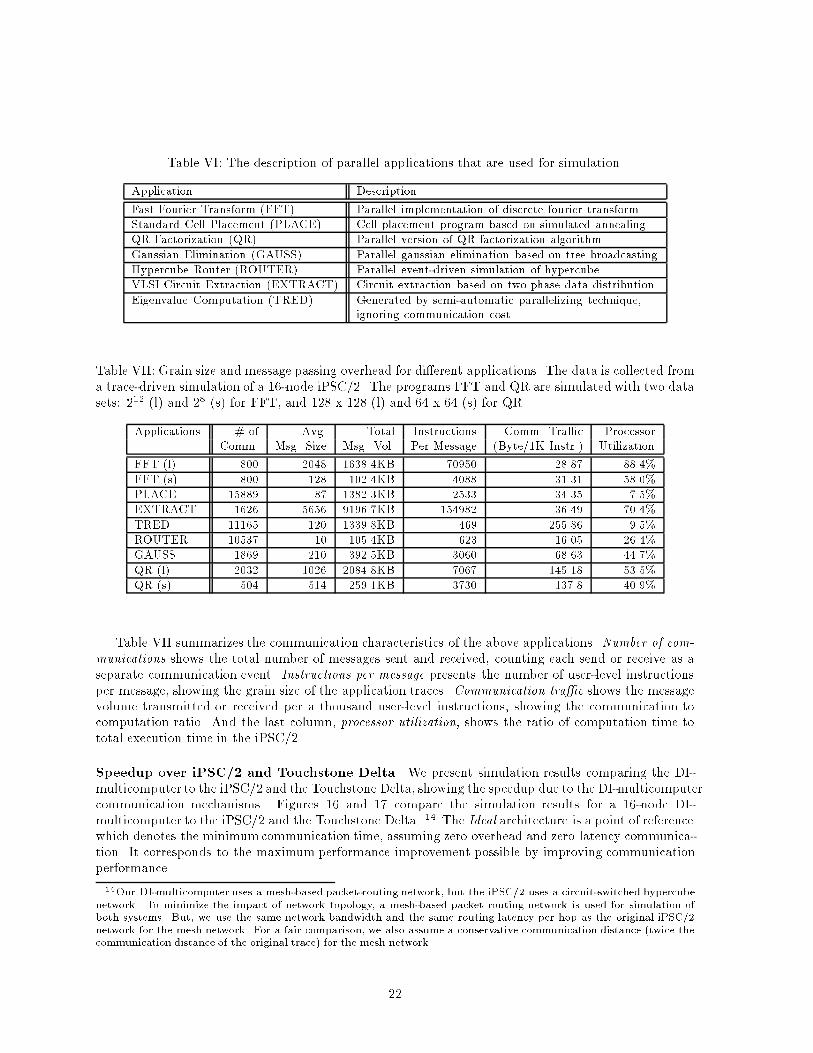
Table VI: The description of parallel applications that are used for simulation.Application DescriptionFast Fourier Transform (FFT) Parallel implementation of discrete fourier transformStandard Cell Placement (PLACE) Cell placement program based on simulated annealingQR Factorization (QR) Parallel version of QR factorization algorithmGaussian Elimination (GAUSS) Parallel gaussian elimination based on tree broadcastingHypercube Router (ROUTER) Parallel event-driven simulation of hypercubeVLSI Circuit Extraction (EXTRACT) Circuit extraction based on two phase data distributionEigenvalue Computation (TRED) Generated by semi-automatic parallelizing technique,ignoring communication costTable VII: Grain size and message passing overhead for di�erent applications. The data is collected froma trace-driven simulation of a 16-node iPSC/2. The programs FFT and QR are simulated with two datasets: 212 (l) and 28 (s) for FFT, and 128 x 128 (l) and 64 x 64 (s) for QR.Applications # of Avg. Total Instructions Comm. Tra�c ProcessorComm. Msg. Size Msg. Vol. Per Message (Byte/1K Instr.) UtilizationFFT (l) 800 2048 1638.4KB 70950 28.87 88.4%FFT (s) 800 128 102.4KB 4088 31.31 58.0%PLACE 15889 87 1382.3KB 2533 34.35 7.5%EXTRACT 1626 5656 9196.7KB 154982 36.49 70.4%TRED 11165 120 1339.8KB 469 255.86 9.5%ROUTER 10537 10 105.4KB 623 16.05 26.4%GAUSS 1869 210 392.5KB 3060 68.63 44.7%QR (l) 2032 1026 2084.8KB 7067 145.18 53.5%QR (s) 504 514 259.1KB 3730 137.8 40.9%Table VII summarizes the communication characteristics of the above applications. Number of com-munications shows the total number of messages sent and received, counting each send or receive as aseparate communication event. Instructions per message presents the number of user-level instructionsper message, showing the grain size of the application traces. Communication tra�c shows the messagevolume transmitted or received per a thousand user-level instructions, showing the communication tocomputation ratio. And the last column, processor utilization, shows the ratio of computation time tototal execution time in the iPSC/2.Speedup over iPSC/2 and Touchstone Delta We present simulation results comparing the DI-multicomputer to the iPSC/2 and the Touchstone Delta, showing the speedup due to the DI-multicomputercommunication mechanisms. Figures 16 and 17 compare the simulation results for a 16-node DI-multicomputer to the iPSC/2 and the Touchstone Delta. 14 The Ideal architecture is a point of referencewhich denotes the minimumcommunication time, assuming zero overhead and zero latency communica-tion. It corresponds to the maximum performance improvement possible by improving communicationperformance.14Our DI-multicomputer uses a mesh-based packet-routing network, but the iPSC/2 uses a circuit-switched hypercubenetwork. To minimize the impact of network topology, a mesh-based packet routing network is used for simulation ofboth systems. But, we use the same network bandwidth and the same routing latency per hop as the original iPSC/2network for the mesh network. For a fair comparison, we also assume a conservative communication distance (twice thecommunication distance of the original trace) for the mesh network.22
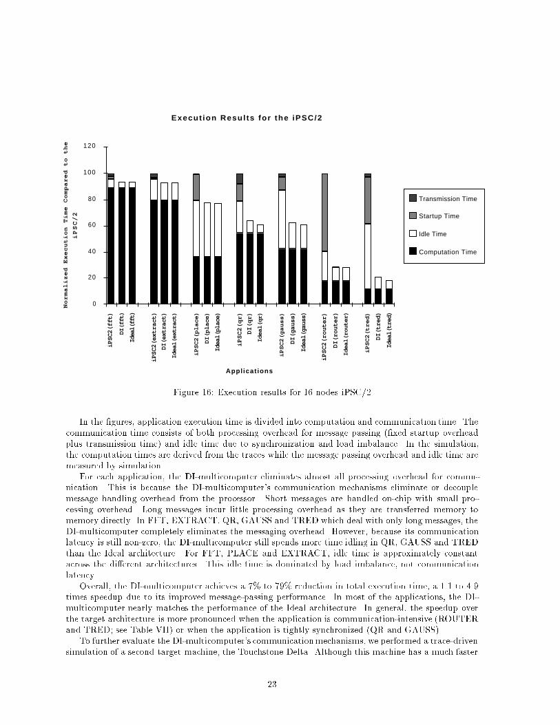
Execut ion Resu l ts fo r the iPSC/2
Appl icat ions
Normalized Execution Time Compared to the
iPSC/2
0
20
40
60
80
100
120
iPSC2(fft)
DI(fft)
Ideal(fft)
iPSC2(extract)
DI(extract)
Ideal(extract)
iPSC2(place)
DI(place)
Ideal(place)
iPSC2(qr)
DI(qr)
Ideal(qr)
iPSC2(gauss)
DI(gauss)
Ideal(gauss)
iPSC2(router)
DI(router)
Ideal(router)
iPSC2(tred)
DI(tred)
Ideal(tred)
Transmission Time
Startup Time
Idle Time
Computation Time
Figure 16: Execution results for 16 nodes iPSC/2In the �gures, application execution time is divided into computation and communication time. Thecommunication time consists of both processing overhead for message passing (�xed startup overheadplus transmission time) and idle time due to synchronization and load imbalance. In the simulation,the computation times are derived from the traces while the message passing overhead and idle time aremeasured by simulation.For each application, the DI-multicomputer eliminates almost all processing overhead for commu-nication. This is because the DI-multicomputer's communication mechanisms eliminate or decouplemessage handling overhead from the processor. Short messages are handled on-chip with small pro-cessing overhead. Long messages incur little processing overhead as they are transferred memory tomemory directly. In FFT, EXTRACT, QR, GAUSS and TRED which deal with only long messages, theDI-multicomputer completely eliminates the messaging overhead. However, because its communicationlatency is still non-zero, the DI-multicomputer still spends more time idling in QR, GAUSS and TREDthan the Ideal architecture. For FFT, PLACE and EXTRACT, idle time is approximately constantacross the di�erent architectures. This idle time is dominated by load imbalance, not communicationlatency.Overall, the DI-multicomputer achieves a 7% to 79% reduction in total execution time, a 1.1 to 4.9times speedup due to its improved message-passing performance. In most of the applications, the DI-multicomputer nearly matches the performance of the Ideal architecture. In general, the speedup overthe target architecture is more pronounced when the application is communication-intensive (ROUTERand TRED; see Table VII) or when the application is tightly synchronized (QR and GAUSS).To further evaluate the DI-multicomputer's communicationmechanisms, we performed a trace-drivensimulation of a second target machine, the Touchstone Delta. Although this machine has a much faster23
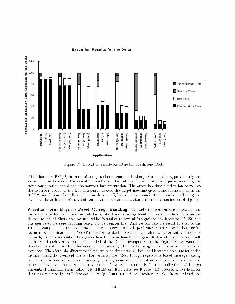
Execut ion Resul ts for the Del ta
Appl icat ions
Normalized Execution Time Compared to the Delta
0
20
40
60
80
100
120
Delta(fft)
DI(fft)
Ideal(fft)
Delta(extract)
DI(extract)
Ideal(extract)
Delta(place)
DI(place)
Ideal(place)
Delta(qr)
DI(qr)
Ideal(qr)
Delta(gauss)
DI(gauss)
Ideal(gauss)
Delta(router)
DI(router)
Ideal(router)
Delta(tred)
DI(tred)
Ideal(tred)
Transmission Time
Startup Time
Idle Time
Computation Time
Figure 17: Execution results for 16 nodes Touchstone DeltaCPU than the iPSC/2, its ratio of computation to communication performance is approximately thesame. Figure 17 shows the execution results for the Delta and the DI-multicomputer assuming thesame computation speed and the network implementation. The execution time distribution as well asthe relative speedup of the DI-multicomputer over the target machine gives almost identical as in theiPSC/2 simulation. Overall, applications become slightly more communication intensive, re ecting thefact that the architecture's ratio of computation to communication performance has increased slightly.Speedup versus Register Based Message Handling To study the performance impact of thememory hierarchy tra�c overhead of the register based message handling, we simulate an another ar-chitecture, called Short architecture, which is similar to several �ne-grained architectures [15, 29] andhas user level message handling based on the register �le. And we compare its result to that of theDI-multicomputer. In this experiment, since message passing is performed at user level in both archi-tectures, we eliminate the e�ect of the software startup cost and are able to factor out the memoryhierarchy tra�c overhead of the register based message handling. Figure 18 shows the simulation resultof the Short architecture compared to that of the DI-multicomputer. In the Figure 18, we count in-struction execution overhead for message load, message store and message transmission as transmissionoverhead. Therefore, the di�erences in transmission time between both architectures accounts for addedmemory hierarchy overhead of the Short architecture. Even though register-�le based message passingcan reduce the startup overhead of message passing, it increases the instruction execution overhead dueto transmission and memory hierarchy tra�c. As a result, especially for the applications with largeamounts of communication tra�c (QR, TRED and ROUTER, see Figure VII), processing overhead forthe memory hierarchy tra�c becomes more signi�cant in the Short architecture. On the other hand, the24
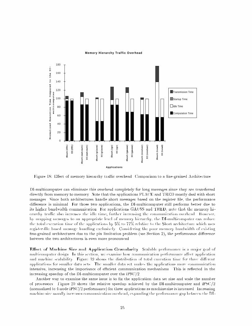
Memory H ie rarchy Tra f f i c Overhead
Appl icat ions
Normalized Execution Time Compared to the DI-
multicomputer
0
20
40
60
80
100
120
140
160
180Short(fft)
DI(fft)
Short(extract)
DI(extract)
Short(place)
DI(place)
Short(qr)
DI(qr)
Short(gauss)
DI(gauss)
Short(router)
DI(router)
Short(tred)
DI(tred)
Transmission Time
Startup Time
Idle Time
Computation Time
Figure 18: E�ect of memory hierarchy tra�c overhead. Comparison to a �ne-grained ArchitectureDI-multicomputer can eliminate this overhead completely for long messages since they are transferreddirectly from memory to memory. Note that the applications PLACE and TRED mostly deal with shortmessages. Since both architectures handle short messages based on the register �le, the performancedi�erence is minimal. For those two applications, the DI-multicomputer still performs better due toits higher bandwidth communication. For applications GAUSS and TRED, note that the memory hi-erarchy tra�c also increases the idle time, further increasing the communication overhead. However,by mapping messages to an appropriate level of memory hierarchy, the DI-multicomputer can reducethe total execution time of the applications by 5% to 77% relative to the Short architecture which usesregister-�le based message handling exclusively. Considering the poor memory bandwidth of existing�ne-grained architectures due to the pin limitation problem (see Section 2), the performance di�erencebetween the two architectures is even more pronounced.E�ect of Machine Size and Application Granularity Scalable performance is a major goal ofmulticomputer design. In this section, we examine how communication performance a�ect applicationand machine scalability. Figure 19 shows the distribution of total execution time for three di�erentapplications for smaller data sets. The smaller data set makes the applications more communicationintensive, increasing the importance of e�cient communication mechanisms. This is re ected in theincreasing speedup of the DI-multicomputer over the iPSC/2.Another way to examine the same issue is to �x the application data set size and scale the numberof processors. Figure 20 shows the relative speedup achieved by the DI-multicomputer and iPSC/2(normalized to 4-node iPSC/2 performance) for three applications as machine size is increased. Increasingmachine size usually increases communication overhead, expanding the performance gap between the DI-25
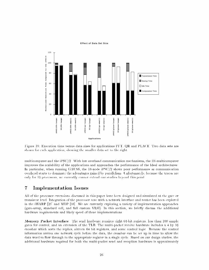
E f f e c t o f D a t a S e t S i z e
Appl ica t ions
Normalized Execution Time Compared to the iPSC/2
0
20
40
60
80
100
120
iPSC2(fft-large)
DI(fft-large)
iPSC2(fft-small)
DI(fft-small)
iPSC2(qr-large)
DI(qr-large)
iPSC2(qr-small)
DI(qr-small)
iPSC2(place-large)
DI(place-large)
iPSC2(place-small)
DI(place-small)
Transmission Time
Startup Time
Idle Time
Computation Time
Figure 19: Execution time versus data sizes for applications FFT, QR and PLACE. Two data sets areshown for each application, showing the smaller data set to the right.multicomputer and the iPSC/2. With low overhead communication mechanisms, the DI-multicomputerimproves the scalability of the applications and approaches the performance of the Ideal architectures.In particular, when running GAUSS, the 16-node iPSC/2 shows poor performance as communicationoverhead starts to dominate the advantages gained by parallelism. Unfortunately, because the traces areonly for 16 processors, we currently cannot extend our studies beyond this point.7 Implementation IssuesAll of the processor extensions discussed in this paper have been designed and simulated at the gate ortransistor level. Integration of the processor core with a network interface and router has been exploredin the iWARP [29] and MDP [16]. We are currently exploring a variety of implementation approaches(gate-array, standard cell, and full custom VLSI). In this section, we brie y discuss the additionalhardware requirements and likely speed of these implementations.Memory Packet Interface The send hardware requires eight 64-bit registers, less than 100 simplegates for control, and an extension of the TLB. The multi-packet receive hardware includes a 4 by 16crossbar which sorts the replies, sixteen 64 bit registers, and some control logic. Because the controlinformation arrives one network cycle before the data, the crossbar can be set up in time to allow thedata word to ow through to the appropriate register in a single cycle. Based on our design studies, theadditional hardware required for both the multi-packet send and reception hardware is approximately26
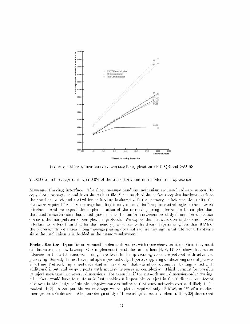
� iPSC/2 Communication � DI Communication Ideal Communication
|2.00
|4.00
|6.00
|8.00
|10.00
|12.00
|14.00
|16.00
|18.00
|
0.0000
|
0.5000
|
1.0000
|
1.5000
|
2.0000
|
2.5000
|
3.0000
|
3.5000
|
4.0000
|
4.5000
|
5.0000
|
5.5000
|
6.0000
|
6.5000
Effect of Increasing System Size
Number of Nodes
Rel
ativ
e S
peed
up C
ompa
red
to 4
Nod
e iP
SC
/2
QR
QR
QR
FFTFFTFFT
GAUSS
GAUSSGAUSS
�
�
�
�
�
�
�
�
�
�
�
�
�
� �
�
�
�
Figure 20: E�ect of increasing system size for application FFT, QR and GAUSS26,000 transistors, representing � 0.6% of the transistor count in a modern microprocessor.Message Passing interface The short message handling mechanism requires hardware support tocopy short messages to and from the register �le. Since much of the packet reception hardware such asthe crossbar switch and control for path setup is shared with the memory packet reception units, thehardware required for short message handling is only message bu�ers plus control logic in the networkinterface. And we expect the implementation of the message passing interface to be simpler thanthat used in conventional bus-based systems since the uniform interconnect of dynamic interconnectionobviates the manipulation of complex bus protocols. We expect the hardware overhead of the networkinterface to be less than that for the memory packet receive hardware, representing less than 0.5% ofthe processor chip die area. Long message passing does not require any signi�cant additional hardwaresince the mechanism is embedded in the memory subsystem.Packet Router Dynamic interconnection demands routers with three characteristics: First, they mustexhibit extremely low latency. Our implementation studies and others [4, 8, 17, 33] show that routerlatencies in the 5-10 nanosecond range are feasible if chip crossing costs are reduced with advancedpackaging. Second, it must have multiple input and output ports, supplying or absorbing several packetsat a time. Network implementation studies have shown that wormhole routers can be augmented withadditional input and output ports with modest increases in complexity. Third, it must be possibleto inject messages into several dimensions. For example, if the network used dimension-order routing,all packets would have to route in X �rst, making it impossible to inject in the Y dimension. Recentadvances in the design of simple adaptive routers indicates that such networks overhead likely to bemodest [4, 8]. A comparable router design we completed required only 18 M�2, � 1% of a modernmicroprocessor's die area. Also, our design study of three adaptive routing schemes [5, 9, 28] shows that27
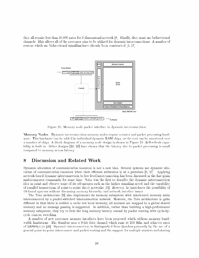
they all require less than 10,000 gates for 2-dimensional network [8]. Finally, they must use bidirectionalchannels. This allows all of the processor pins to be utilized for dynamic interconnections. A number ofrouters which use bidirectional signalling have already been constructed [5, 17].DECODER
Row Buffer
Refresh ControlR/W
Column Multiplexer/Demultiplexer
typedata
Control
From Router
typedata tagTo Router
RAMArray
Basic DRAM Core
source
source
page off
pagenum size off tag
pageooff
pagenum
size offFigure 21: Memory node packet interface in dynamic interconnectionMemory Nodes Dynamic interconnection memory nodes require a router and packet processing hard-ware. This hardware can be added to individual dynamic RAM chips, or the cost can be amortized overa number of chips. A block diagram of a memory node design is shown in Figure 21. Self-refresh capa-bility is built in. Other designs [30, 20] have shown that the latency due to packet processing is smallcompared to memory access latency.8 Discussion and Related WorkDynamic allocation of communication resources is not a new idea. Several systems use dynamic allo-cation of communication resources when their e�cient utilization is at a premium [6, 27]. Applyingnetwork-based dynamic interconnection to low-level interconnection has been discussed in the �ne-grainmulticomputer community for some time. Seitz was the �rst to describe the dynamic interconnectionidea in print and observe some of its advantages such as the higher signaling speed and the capabilityof parallel transactions of point-to-point direct networks [33]. However, he introduces the possibility ofDI-based systems without discussing memory hierarchy and network interface issues.The Tera architecture [3] also implements its memory subsystem with interleaved memory unitsinterconnected by a packet-switched interconnection network. However, the Tera architecture is quitedi�erent in that there is neither a cache nor local memory; all accesses are mapped to a global sharedmemory and no message passing is supported. In addition, rather than building a high-performancememory subsystem, they try to hide the long memory latency caused by packet routing with cycle-by-cycle context switching.A number of new processor memory interfaces have been proposed which address memory band-width limitations. The Rambus uses a 9-bit data channel which runs at 250 Mhz and achieves ratesof 500MByte/s [30]. Dynamic interconnection is distinguished from Rambus primarily by the use of ageneral point-to-point interconnect and packet routing and the support for multiple masters and sharing28
of memory modules. The Scalable Coherent Interface (IEEE P1596) also uses point-to-point links toachieve high speed signaling [20], but the ring topology used in SCI increases memory access latency.The J-machine [16] addresses message handling overhead with hardware support, by putting thenetwork interface on chip and providing hardware to queue incoming messages. Processor-networkinterface studies for the �T project [21] have addressed the issue of how to couple processors with thenetwork. However, like existing �ne-grained architectures, their register-�le based message handlingsu�ers from the memory hierarchy tra�c overhead. The Fujitsu AP1000 [22] includes hardware supportfor two di�erent message classes. However, its line send mechanism for short messages is based on ahardware managed queue in memory, not an on-chip FIFO as in the DI-multicomputer. This meansthat incoming short messages still need to be fetched from memory, increasing the latency.The issue of implementing global cache coherence is an orthogonal issue to the DI-based systems.Either hardware directory-based coherence protocols [2, 26] or software-based approaches [7, 11] can beimplemented on top of the DI-based systems to support the cache coherence.9 SummaryThe DI-multicomputer uses dynamic interconnection and novel message handling mechanisms to increasein memory bandwidth and reduce message passing overhead. Dynamic interconnection increases chipinput/output bandwidth signi�cantly by sharing pins and using point-to-point interconnects to achievefaster signalling. Our performance comparisons show that DI systems are competitive with conventionalmemory hierarchies at small cache line sizes (32 bytes) and superior for larger line sizes.The DI-multicomputer provides distinct mechanisms for short and long messages, achieving a signif-icant reduction in communication overhead. For short messages, register based short message handlingeliminates startup costs. For long messages, the parallel memory-to-memory block transfer produceshigh bandwidth, low latency communication. Using two distinct message passing mechanisms allowsmessages to be handled at an appropriate level of the memory hierarchy, reducing cache perturbationand avoiding unnecessary data transfers.Our simulation results show that the novel message passing mechanisms of the DI-multicomputercan achieve up to 4 times speedup. Also, by sending messages to appropriate level of memory hierarchy,the DI-multicomputer can eliminate most of the memory hierarchy tra�c overhead, which is inevitablein register based message handling. The two level message passing mechanisms can give up to a 77% increase in performance compared to register based message passing. The robust communicationperformance of the DI-multicomputer on enables it to excel existing multicomputer architectures on both�ne-grained and coarse-grained applications. Our studies con�rm that the DI-multicomputer achievesmore robust scalable performance for larger machine sizes than the target architectures.We have only begun to explore the possibilities of dynamic interconnection-based systems. There area number of obvious optimizations: express cubes [13] can reduce the routing penalty in the dynamicinterconnection and the network/memory hierarchy interference, and extremely large messages can bebroken into several MOVE instructions to exploit greater communication parallelism, etc. The globalphysical address space can support a variety of additional functionality. For example, memory can bepooled amongst processors, providing some advantages of shared memory machines. Alternatively, thefree association between memory and processors can be used to build a variable grain-size machine. Onemajor issue that remains is the evaluation of the contention memory and communication tra�c and itsimpact on the performance. We are currently performing a detail simulation of the DI-multicomputermemory hierarchy based on application memory traces to address this question.Acknowledgements The research described in this paper was supported in part by NSF grants CCR-9209336 andMIP-92-23732, ONR grants N00014-92-J-1961 and N00014-93-1-1086and NASA grant NAG1-613. Additional support has been provided by the National Science Foundation under Grant No. MIP89-20891 and MIP 93-07910 and by a generous special-purpose grant from the AT&T Foundation. We29
would like to thank the reviewers for their valuable comments and suggestions. We also wish to thankMichael Peercy at IBM Almaden and Jim Hsu at HP Laboratory for their guidance on the trace-drivensimulation, and Professor Prith Banerjee at Coordinated Science Laboratory for providing us the traces.Our warmest thanks to Professor Pen-Chung Yew at University of Minnesota for his encouragement andsupports.References[1] Agarwal, A., Lim, B.-H., Kranz, D., and Kubiatowicz, J. April: a processor architecture for multipro-cessing. In Proceedings of the 17th Annual International Symposium on Computer Architecture, pp. 104{114,May 1990.[2] Agarwal, A., and et al. The MIT Alewife Machine: A Large-Scale Distributed-Memory Multiprocessor.In Proceedings of Workshop on Scalable Shared Memory Multiprocessors, 1991.[3] Alverson, G., Alverson, R., Callahan, D., Koblenz, B., Porterfield, A., and Smith, B. Exploit-ing heterogeneous parallelism on a multithreaded multiprocessor. In Proceedings of the 6th ACM InterationalConference on Supercomputing, 1992.[4] Aoyama, K. The cost of adaptivity and virtual lanes in a wormhole router. In Journal of VLSI Design,1994.[5] Berman, P., Gravano, L., Pifarre, G., and Sanz, J. Adaptive deadlock and livelock free routingwith all minimal paths in torus networks. In Proceedings of the Symposium on Parallel Algorithms andArchitectures, 1992.[6] Cerf, V., and Kahn, R. A protocol for packet network interconnection. IEEE Transactions on Commu-nications, 1974.[7] Cheong, H. Life Span Strategy - A Compiler-Based Approach to Cache Coherence. In Proceedings of theInternational Conference on Supercomputing, 1992.[8] Chien, A. A. A cost and speed model for k-ary n-cube wormhole routers. multiprocessors. In Proceedingsof the Hot Interconnects, 1993.[9] Chien, A. A., and Kim, J. H. Planar-adaptive routing: Low-cost adaptive networks for multiprocessors.In Proceedings of the International Symposium on Computer Architecture, pp. 268{77, May 1992.[10] Choi, L., and Chien, A. Integrating networks and memory hierarchies in a multicomputer node architec-ture. In Proceedings of the International Parallel Processing Symposium, April 1994.[11] Choi, L., and Yew, P. C. ACompiler-Directed Cache Coherence Scheme with Improved Intertask Locality.In Proceedings of the ACM/IEEE Supercomputing, pp. 773{782, November 1994.[12] Cray Research Inc. SHMEM User's Guide. 1994.[13] Dally, W. J. Express cubes: Improving the performance of k-ary n-cube interconnection networks. IEEETransactions on Computers, 40(9):1016{1023, 1991.[14] Dally, W. J. Virtual channel ow control. IEEE Transactions on Parallel and Distributed Systems,3(2):194{205, 1992.[15] Dally, W. J., Chien, A., Fiske, S., Horwat, W., Keen, J., Larivee, M., Lethin, R., Nuth, P.,Wills, S., Carrick, P., and Fyler, G. The J-Machine: A �ne-grain concurrent computer. In InformationProcessing 89, Proceedings of the IFIP Congress, pp. 1147{1153, August 1989.[16] Dally, W. J., Fiske, J. A. S., Keen, J. S., Lethin, R. A., Noakes, M. D., Nuth, P. R., Davison,R. E., and Fyler, G A. The message-driven processor. IEEE Micro, April 1992.[17] Dally, W. J., and Song, P. Design of a self-timed vlsi multicomputer communication controller. InProceedings of the International Conference on Computer Design, pp. 230{4. IEEE Computer Society,1987.[18] Davidson, E. E. Electrical design of a high speed computer packaging system. IEEE Transactions onComponents, Hybrids and Manufacturing Technology, CHMT-6(3):272{282, 1983.[19] Digital Equipment Corporation. Alpha Architecture Handbook, 1992.30
[20] Gustavson, D. B. The scalable coherent interface and related standards projects. IEEE Micro, 12(1), Feb.1992.[21] Henry, D. S., and Joerg, C. F. A tightly-coupled processor-network interface. In Proceedings of theFifth International Conference on Architectural Support for Programming Languages an Operating Systems,pp. 111{122, 1992.[22] Horie, T., et al. AP1000 architecture and performance of LU decomposition. In International Conferenceon Parallel Processing, 1991.[23] Hsu, J. M. Performance measurement and hardware support for message passing distributed memorymultiprocessors. Technical Report UILC-ENG-91-2209, University of Illinois, Center for Reliable and High-Performance Computing, 1991.[24] Intel Corporation. i860 XP Microprocessor Data Book, 1991.[25] Intel Corporation. Paragon XP/S Product Overview, 1991.[26] D., Laudon, J., Gharachorloo, K., Gupta, A., and Hennessy, J. The Directory-Based Cache Co-herence Protocol for the DASH Computer. In Proceedings of the 17th Annual International Symposium onComputer Architecture, pp. 148{159, May 1990.[27] Metcalfe, R., and Boggs, D. Ethernet: Distributed packet-switching for local computer networks.Communications of the Association for Computing Machinery, 19(7):395{404, 1976.[28] Ni, L., and Glass, C. The turn model for adaptive routing. In Proceedings of the International Symposiumon Computer Architecture, 1992.[29] Peterson, C., Sutton, J., and Wiley, P. iWarp: a 100-MOPS LIW microprocessor for multicomputers.IEEE Micro, June 1991.[30] Rambus Corporation. Rambus architectural overview. Product Literature, 1992.[31] Matsui, N., Satoh, H., and Okada, K. Analysis of high-speed bus lines in printed circuit boards. InIEEE/CHMT Japan IEMT Symposium, pp. 156{167. IEEE, 1989.[32] Seitz, C., and Su, W. A family of routing and communication chips based on the Mosaic. In Proceedingsof the University of Washington Symposium on Integrated Systems, 1993.[33] Seitz, C. L. Let's route packets instead of wires. In W. J. Dally, editor, Proceedings of the 6th MITConference on Advanced Research in VLSI, pp. 133{37. MIT Press, 1990.[34] Thinking Machines Corporation, Cambridge, Massachusetts. CM-5 Technical Summary, October1991.[35] Whitby-Strevens, C. The transputer. In Proceedings of 12th International Symposium on ComputerArchitecture, 1985.A Packet FormatsB Instruction Set ArchitectureThe DI-microprocessor has a basic RISC instruction set augmented with special communication, syn-chronization and translation instructions. All registers are addressed relative to a context o�set (CO) inthe process status register. In this section, only the new instructions added to DEC Alpha instructionset will be described.All the new instructions are described using a simple format which can be implemented by anyinstruction format of a modern RISC microprocessor. The operand types of the format are shown inTable VIII. The detail �eld speci�cation of the operand types is assumed to be speci�ed according tothe DEC Alpha instruction format shown in Figure 24.31
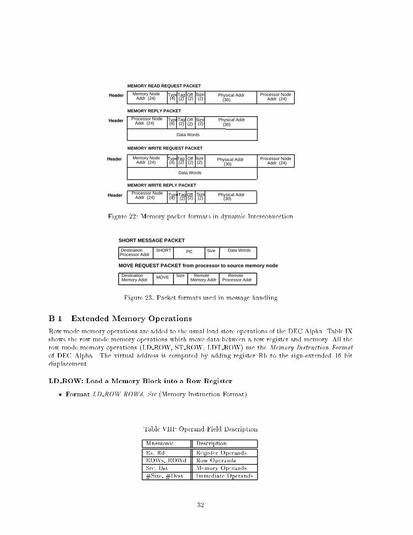
Header
Header
Header
Header
Tag Off
Data Words
Data Words
Type Size Physical Addr
Tag Off Type Size Physical Addr
Tag Off Type Size Physical Addr
(2) (2) (2)
(2) (2) (2)
(2) (2) (2)
Tag Off Type Size Physical Addr(2) (2) (2)
MEMORY READ REQUEST PACKET
MEMORY REPLY PACKET
MEMORY WRITE REQUEST PACKET
MEMORY WRITE REPLY PACKET
Memory Node Addr (24)
Processor Node Addr (24)
Memory Node Addr (24)
Processor Node Addr (24)
(4)
(4)
(4)
(4)
(30)
(30)
(30)
(30)
Processor Node Addr (24)
Processor Node Addr (24)Figure 22: Memory packet formats in dynamic Interconnection
Size
DestinationProcessor Addr
PC
MOVE REQUEST PACKET from processor to source memory node
SHORT MESSAGE PACKET
Size
DestinationMemory Addr
RemoteMemory Addr
RemoteProcessor Addr
SHORT Data Words
MOVEFigure 23: Packet formats used in message handlingB.1 Extended Memory OperationsRow mode memory operations are added to the usual load store operations of the DEC Alpha. Table IXshows the row mode memory operations which move data between a row register and memory. All therow mode memory operations (LD ROW, ST ROW, LDT ROW) use the Memory Instruction Formatof DEC Alpha. The virtual address is computed by adding register Rb to the sign-extended 16 bitdisplacement.LD ROW: Load a Memory Block into a Row Register� Format LD ROW ROWd, Src (Memory Instruction Format)Table VIII: Operand Field DescriptionMnemonic DescriptionRs, Rd Register OperandsROWs, ROWd Row OperandsSrc, Dst Memory Operands#Size, #Dest Immediate Operands32
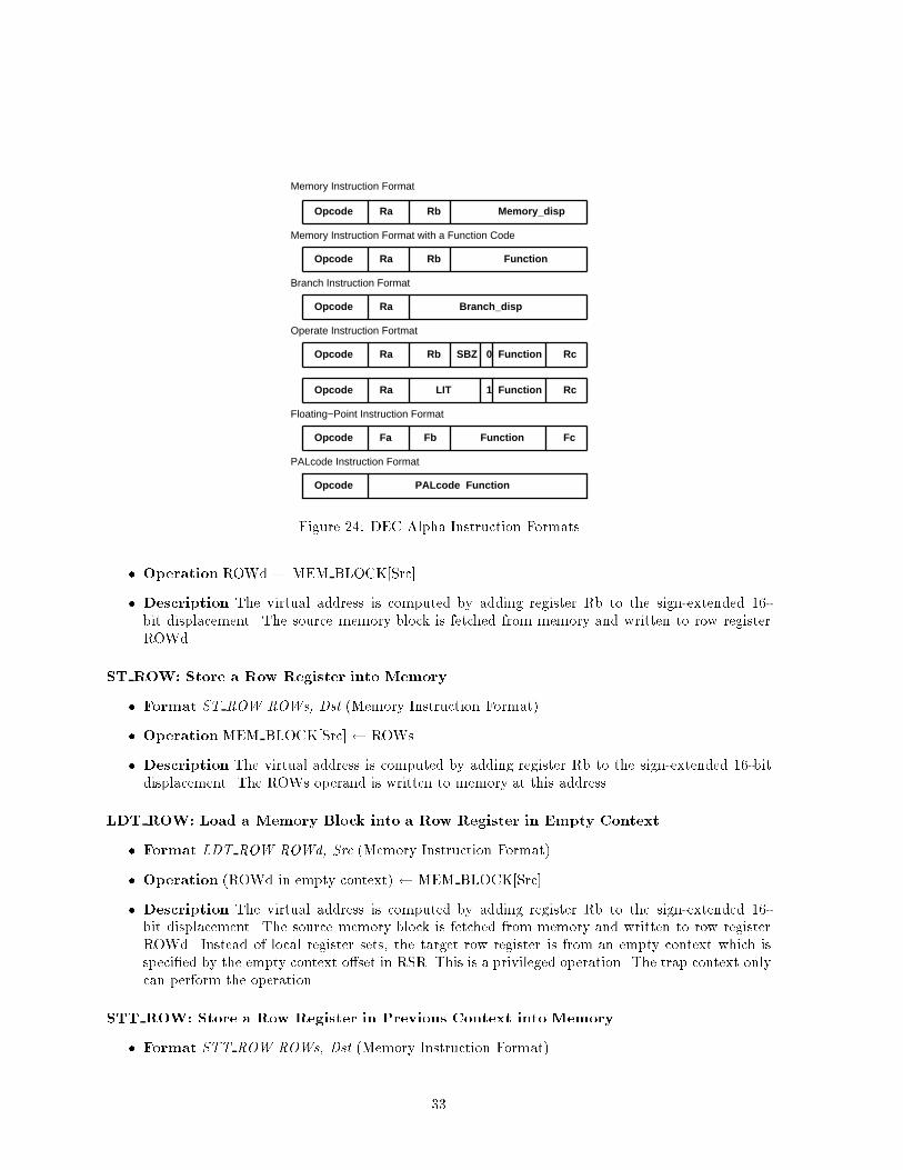
Opcode Ra Rb Memory_disp
Opcode Ra Rb Function
Opcode Ra Branch_disp
Opcode Ra Rb SBZ 0 Function Rc
Opcode Ra Function Rc1 LIT
Memory Instruction Format
Memory Instruction Format with a Function Code
Branch Instruction Format
Operate Instruction Fortmat
Floating−Point Instruction Format
Opcode FunctionFa Fb Fc
PALcode Instruction Format
Opcode PALcode FunctionFigure 24: DEC Alpha Instruction Formats� Operation ROWd MEM BLOCK[Src]� Description The virtual address is computed by adding register Rb to the sign-extended 16-bit displacement. The source memory block is fetched from memory and written to row registerROWd.ST ROW: Store a Row Register into Memory� Format ST ROW ROWs, Dst (Memory Instruction Format)� OperationMEM BLOCK[Src] ROWs� Description The virtual address is computed by adding register Rb to the sign-extended 16-bitdisplacement. The ROWs operand is written to memory at this address.LDT ROW: Load a Memory Block into a Row Register in Empty Context� Format LDT ROW ROWd, Src (Memory Instruction Format)� Operation (ROWd in empty context) MEM BLOCK[Src]� Description The virtual address is computed by adding register Rb to the sign-extended 16-bit displacement. The source memory block is fetched from memory and written to row registerROWd. Instead of local register sets, the target row register is from an empty context which isspeci�ed by the empty context o�set in RSR. This is a privileged operation. The trap context onlycan perform the operation.STT ROW: Store a Row Register in Previous Context into Memory� Format STT ROW ROWs, Dst (Memory Instruction Format)33
� OperationMEM BLOCK[Dst] (ROWs in previous context)� Description The virtual address is computed by adding register Rb to the sign-extended 16-bitdisplacement. The ROWs operand is written to memory at the speci�ed address. Instead of localregister sets, the source row register is from the previously running context which is speci�ed bythe previous context o�set in RSR. This is also a privileged operation. The trap context only canperform the operation.There are two additional memory operations used for long message transfer. One (STV) is usedfor reception of a long message and the other (TEST) is used for synchronization. Executing an STVinstruction allocates a dummy cache line which will hold the acknowledgments from the memory. Thereis no source operand speci�ed. Therefore, the speci�ed target memory word will remain unchanged byexecuting this virtual store instruction. The TEST instruction checks whether the location contains allthe acknowledgments from the memory nodes. If not, the thread executing the instruction will blockuntil the acknowledgments arrive. This instruction allows synchronization between the receiving threadand message reception at destination node.STV: Store a Register Data into Memory Virtually� Format STV Dst (Memory Instruction Format)� Operation allocate CACHE BLOCK[Dst]� Description The virtual address is computed by adding register Rb to the sign-extended 16-bitdisplacement. A cache block is allocated for the target address but the instruction will not a�ectthe corresponding memory block. The source register operand �eld is not used.TEST: Test memory location� Format TEST Src (Memory Instruction Format)� Operation if CACHE BLOCK[Src] = `ACK' then ftest succeeds and returnsg else block� Description The virtual address is computed by adding register Rb to the sign-extended 16-bitdisplacement. The register operand �eld is not used.B.2 Message OperationsTable IX also shows the message send instructions in DI-microprocessor. SEND is used for short messagetransfers while MOVE is used for long block transfers. The source operand Rs in the SEND instructionspeci�es the �rst register of the transmitted messages in the register �le, and the size �eld speci�es thelength of the message. All the message handling instructions use the Operate Instruction Format ofDEC Alpha. All the immediate �elds use the literal �eld of the instruction format. The source addressshould be local and the destination memory address should be remote in the MOVE instruction. Sincethe MOVE instruction needs more than 2 source register operands, it may need another cycle to decodeand fetch all the register operands speci�ed depending on the implementation.SEND: Send a short message� Format SEND Rs, #Size (Operate Instruction Format)� Operation Router Message in Rs; Rs+1; ::Rs+size�1� Description The message should be contiguous in the speci�ed registers. The message is copiedinto router port by the network interface. 34
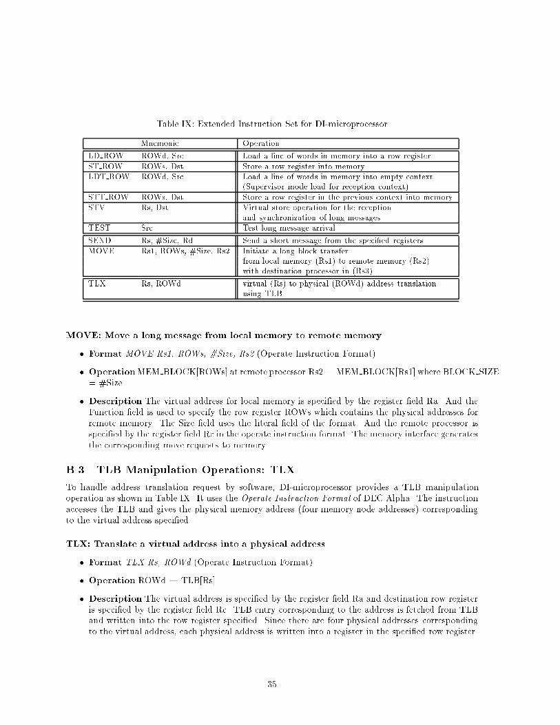
Table IX: Extended Instruction Set for DI-microprocessorMnemonic OperationLD ROW ROWd, Src Load a line of words in memory into a row registerST ROW ROWs, Dst Store a row register into memoryLDT ROW ROWd, Src Load a line of words in memory into empty context(Supervisor mode load for reception context)STT ROW ROWs, Dst Store a row register in the previous context into memorySTV Rs, Dst Virtual store operation for the receptionand synchronization of long messagesTEST Src Test long message arrivalSEND Rs, #Size, Rd Send a short message from the speci�ed registersMOVE Rs1, ROWs, #Size, Rs2 Initiate a long block transferfrom local memory (Rs1) to remote memory (Rs2)with destination processor in (Rs3)TLX Rs, ROWd virtual (Rs) to physical (ROWd) address translationusing TLBMOVE: Move a long message from local memory to remote memory� Format MOVE Rs1, ROWs, #Size, Rs2 (Operate Instruction Format)� OperationMEM BLOCK[ROWs] at remote processor Rs2 MEM BLOCK[Rs1] where BLOCK SIZE= #Size� Description The virtual address for local memory is speci�ed by the register �eld Ra. And theFunction �eld is used to specify the row register ROWs which contains the physical addresses forremote memory. The Size �eld uses the literal �eld of the format. And the remote processor isspeci�ed by the register �eld Rc in the operate instruction format. The memory interface generatesthe corresponding move requests to memory.B.3 TLB Manipulation Operations: TLXTo handle address translation request by software, DI-microprocessor provides a TLB manipulationoperation as shown in Table IX. It uses the Operate Instruction Format of DEC Alpha. The instructionaccesses the TLB and gives the physical memory address (four memory node addresses) correspondingto the virtual address speci�ed.TLX: Translate a virtual address into a physical address� Format TLX Rs, ROWd (Operate Instruction Format)� Operation ROWd TLB[Rs]� Description The virtual address is speci�ed by the register �eld Ra and destination row registeris speci�ed by the register �eld Rc. TLB entry corresponding to the address is fetched from TLBand written into the row register speci�ed. Since there are four physical addresses correspondingto the virtual address, each physical address is written into a register in the speci�ed row register.35
BiographyLYNN CHOI is a Ph.D candidate in the Department of Computer Science and a research assis-tant in the Center for Supercomputing Research and Development of University of Illinois at Urbana-Champaign. He received his B.S. and M.S. degree both in computer engineering in 1986 and and in 1988respectively from Seoul National University, Seoul Korea. After the study, he worked at Korea TelecomResearch Center as a technical sta� until 1990. His current research interests include architecture andcompilation issues in high performance computer systems, speci�cally cache and memory system designin large-scale parallel systems. He is a student member of both IEEE and ACM.ANDREW A. CHIEN received his B.S. degree in Electrical Engineering (1984) and his M.S. (1987)and Ph.D. (1990) degrees in Computer Science all from the Massachusetts Institute of Technology. Heis currently an Associate Professor in the Department of Computer Science at the University of Illinoiswhere he leads the Concurrent Systems Architecture Group. His research interests involve the interactionof architecture, system software, compilers, and programming languages in high-performance parallelsystems. Andrew Chien has authored numerous research papers in those areas and recently publishedConcurrent Aggregates: Supporting Modularity in Massively-Parallel Programs with MIT Press. AndrewChien is a member of both IEEE and ACM.
36