Embed Size (px)
Citation preview
THE DESIGN AND EVALUATION OF AHIERARCHICAL OPENFLOW SDN CONTROL PLANE
By
AYAKA KOSHIBE
A thesis submitted to the
Graduate School—New Brunswick
Rutgers, The State University of New Jersey
in partial fulfillment of the requirements
for the degree of
Master of Science
Graduate Program in Electrical and Computer Engineering
written under the direction of
Dipankar Raychaudhuri
and approved by
New Brunswick, New Jersey
October, 2013
ABSTRACT OF THE THESIS
The Design and Evaluation of a Hierarchical OpenFlow SDN
Control Plane
By AYAKA KOSHIBE
Thesis Director:
Dipankar Raychaudhuri
This thesis investigates the design of hierarchical software-defined networks with improved
scalability and service integration. Software Defined Networking (SDN) aims to bring flexi-
bility and intelligence into networks by moving the network stack into logically centralized,
programmable control planes. While distribution schemes and virtualization have addressed
control plane scalability and network stack coexistence, they do so separately as unrelated
subjects, and no unified solution exists. This work addresses the intersection of the two
aspects through a little-explored control plane distribution method in which controllers are
organized into a hierarchy based on service characteristics. Specifically, this thesis addresses
1) the evolution of SDN control plane architectures, focusing on distributed SDNs based on
the OpenFlow SDN control protocol, and 2) the design, implementation, and evaluation of
an architecture for a hierarchical OpenFlow control plane.
A layered model for control plane architecture is presented as a reference for the design.
The widely-adopted Floodlight SDN framework is used to implement a prototype. The
prototype is implemented as a series of modules that extend the base platform to use an
ii
OpenFlow-based inter-controller protocol. This protocol enables controllers to configure
one another based on their positions in the hierarchy, enabling them to coordinate event
handling by the network services at each controller.
This prototype is evaluated on the wired sandboxes of the ORBIT network testbed, with
focus on control plane overhead and scalability. A custom OpenFlow client is used to
measure processing overheads for several control plane topologies. Scalability is evaluated
with respect to event processing rate at the lowest tier, and the amount of requests received
at the upper tiers, of a sample hierarchy. Each controller involved in event handling is found
to add at most about 0.46ms to overhead per packet, discounting network link delays. A
comparison with the stock controller reveals that the control plane scales in event processing
capacity with the number of data plane-facing controllers, and that the volume of requests
at higer tiers are coupled to the types of events requested. We finish with remarks on
potential future improvements to the control plane design.
iii
Table of Contents
Abstract . . . . . . . . . . . . . . . . . . . . . . . . . . . . . . . . . . . . . . . . . . ii
List of Figures . . . . . . . . . . . . . . . . . . . . . . . . . . . . . . . . . . . . . . vi
1. Introduction . . . . . . . . . . . . . . . . . . . . . . . . . . . . . . . . . . . . . 1
1.1. What is SDN, and why? . . . . . . . . . . . . . . . . . . . . . . . . . . . . . 1
1.2. SDN in practice . . . . . . . . . . . . . . . . . . . . . . . . . . . . . . . . . . 3
1.3. Open SDNs and the OpenFlow protocol . . . . . . . . . . . . . . . . . . . . 3
1.4. Organization of this thesis . . . . . . . . . . . . . . . . . . . . . . . . . . . . 4
2. (Open) SDN control planes and trends . . . . . . . . . . . . . . . . . . . . 5
2.1. The single-controller control plane. . . . . . . . . . . . . . . . . . . . . . . . 5
2.2. Distributed control planes. . . . . . . . . . . . . . . . . . . . . . . . . . . . . 6
2.2.1. Distributed control planes - what is missing? . . . . . . . . . . . . . 7
2.3. Heterogeneous control planes . . . . . . . . . . . . . . . . . . . . . . . . . . 8
3. Open SDN Controller Architecture . . . . . . . . . . . . . . . . . . . . . . 10
3.1. The layered control plane model . . . . . . . . . . . . . . . . . . . . . . . . 10
3.2. Floodlight system architecture . . . . . . . . . . . . . . . . . . . . . . . . . 11
3.2.1. Floodlight core components . . . . . . . . . . . . . . . . . . . . . . . 12
3.2.2. Floodlight application modules . . . . . . . . . . . . . . . . . . . . . 13
3.2.3. The packet process chain . . . . . . . . . . . . . . . . . . . . . . . . 13
4. Hierarchical Heterogeneous Control Planes . . . . . . . . . . . . . . . . . . 14
4.1. Motivation for Heterogeneous Control Planes . . . . . . . . . . . . . . . . . 14
4.2. General functions and features . . . . . . . . . . . . . . . . . . . . . . . . . 16
iv
4.2.1. Implications to the architecture . . . . . . . . . . . . . . . . . . . . . 17
4.2.2. Related works . . . . . . . . . . . . . . . . . . . . . . . . . . . . . . . 18
5. Control plane internals . . . . . . . . . . . . . . . . . . . . . . . . . . . . . . . 19
5.1. Inter-controller (Control-plane-level) functions . . . . . . . . . . . . . . . . . 19
5.1.1. Controller Initialization and Discovery . . . . . . . . . . . . . . . . . 20
5.1.2. Route and service propagation . . . . . . . . . . . . . . . . . . . . . 21
5.2. Context preservation . . . . . . . . . . . . . . . . . . . . . . . . . . . . . . . 22
5.3. Event process chain execution . . . . . . . . . . . . . . . . . . . . . . . . . . 23
6. Implementation . . . . . . . . . . . . . . . . . . . . . . . . . . . . . . . . . . . 26
6.1. Inter-controller messaging . . . . . . . . . . . . . . . . . . . . . . . . . . . . 26
6.1.1. The client-server handshake . . . . . . . . . . . . . . . . . . . . . . . 27
6.1.2. Client process chain configuration . . . . . . . . . . . . . . . . . . . 28
6.1.3. Event process chain execution . . . . . . . . . . . . . . . . . . . . . . 29
6.2. Controller role configurations . . . . . . . . . . . . . . . . . . . . . . . . . . 30
7. Evaluation . . . . . . . . . . . . . . . . . . . . . . . . . . . . . . . . . . . . . . . 32
7.1. Control plane overhead . . . . . . . . . . . . . . . . . . . . . . . . . . . . . . 33
7.2. Scalability . . . . . . . . . . . . . . . . . . . . . . . . . . . . . . . . . . . . . 34
7.3. Sample applications. . . . . . . . . . . . . . . . . . . . . . . . . . . . . . . . 35
8. Conclusion . . . . . . . . . . . . . . . . . . . . . . . . . . . . . . . . . . . . . . 40
References . . . . . . . . . . . . . . . . . . . . . . . . . . . . . . . . . . . . . . . . . 42
v
List of Figures
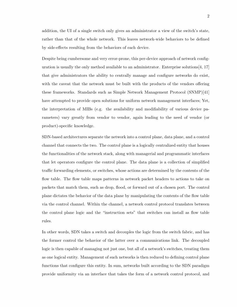
1.1. A generic representation of an SDN-based network, with the components
labeled. The controller can be described as a collection of applications, or
event handlers for the various types of control channel messages it receives
from the data plane. The messages are formatted according to the control
protocol within the channel. . . . . . . . . . . . . . . . . . . . . . . . . . . . 3
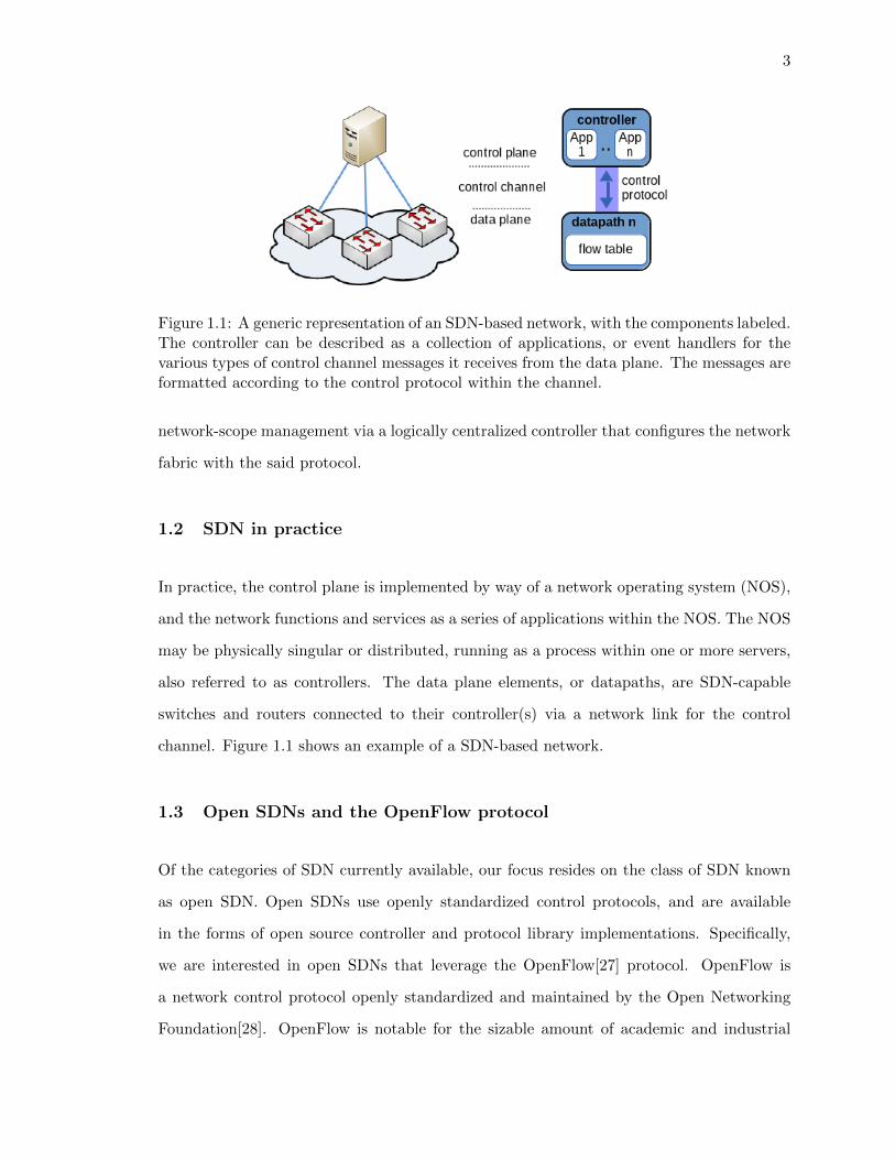
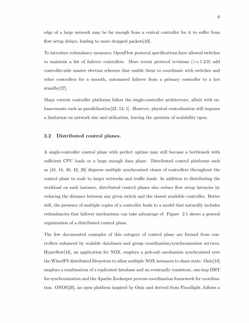
2.1. The datapaths of a distributed control plane may not necessarily connect
to the same controller. The controllers operate on a shared view of the
network with the aid of distributed mechanisms, keeping the data plane’s
state consistent. . . . . . . . . . . . . . . . . . . . . . . . . . . . . . . . . . . 7
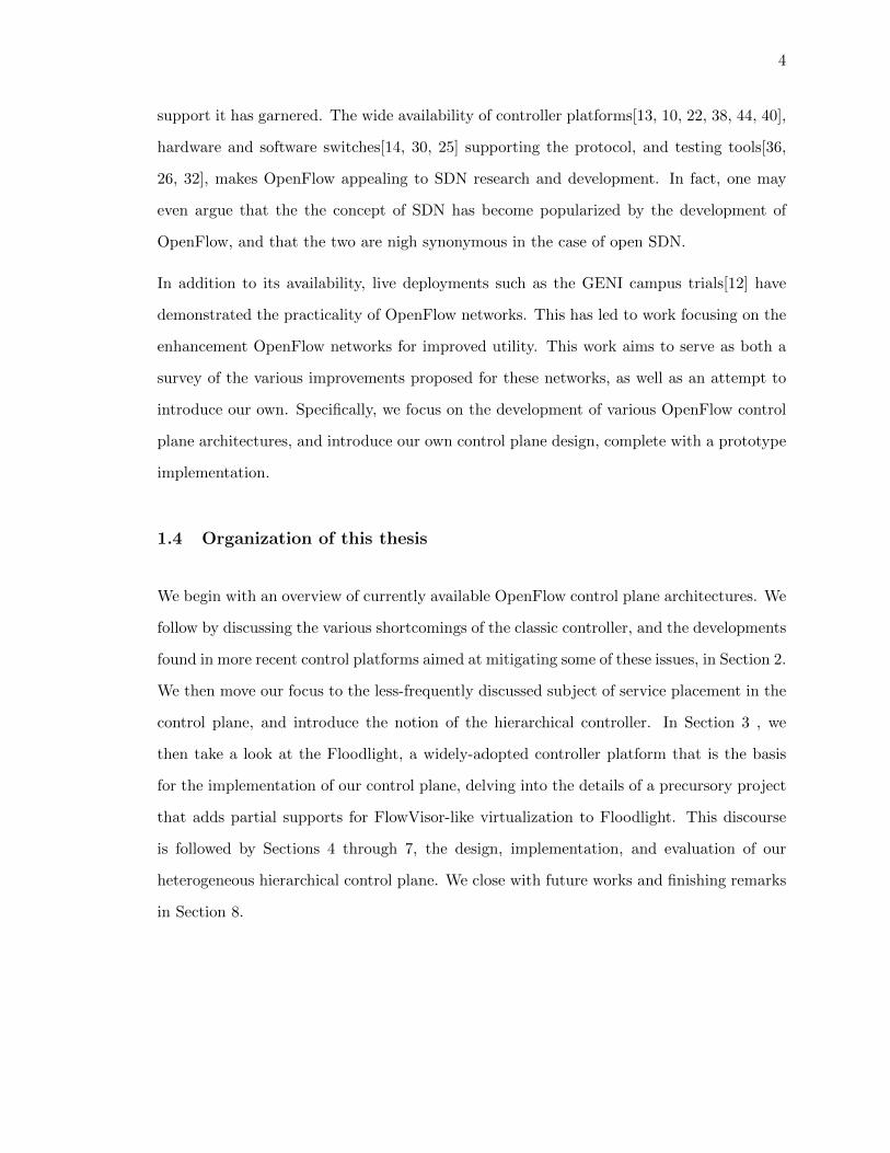
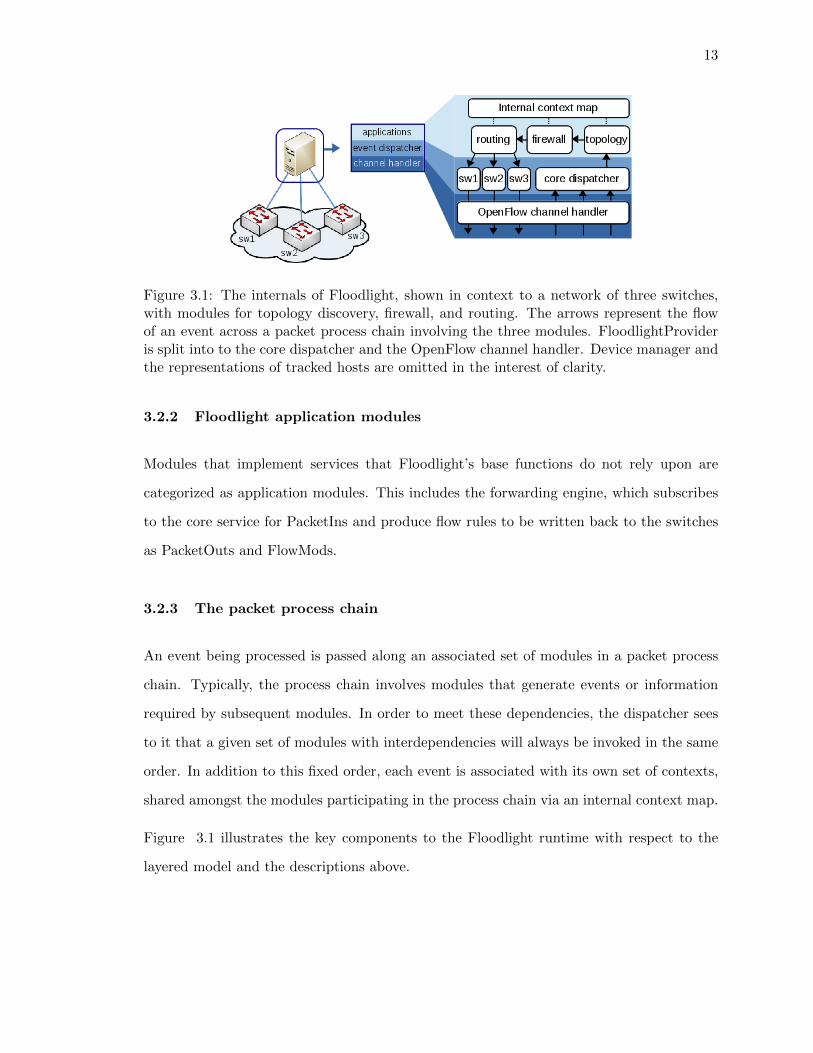
3.1. The internals of Floodlight, shown in context to a network of three switches,
with modules for topology discovery, firewall, and routing. The arrows rep-
resent the flow of an event across a packet process chain involving the three
modules. FloodlightProvider is split into to the core dispatcher and the Open-
Flow channel handler. Device manager and the representations of tracked
hosts are omitted in the interest of clarity. . . . . . . . . . . . . . . . . . . . 13
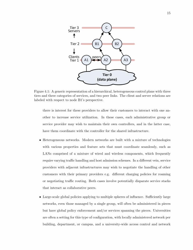
4.1. A generic representation of a hierarchical, heterogeneous control plane with
three tiers and three categories of services, and two peer links. The client
and server relations are labeled with respect to node B1’s perspective. . . . 15
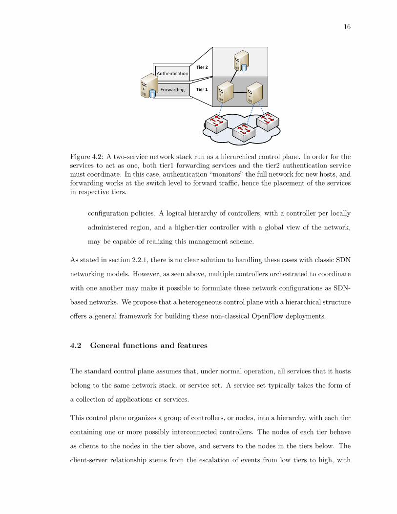
4.2. A two-service network stack run as a hierarchical control plane. In order for
the services to act as one, both tier1 forwarding services and the tier2 au-
thentication service must coordinate. In this case, authentication “monitors”
the full network for new hosts, and forwarding works at the switch level to
forward traffic, hence the placement of the services in respective tiers. . . . 16
vi
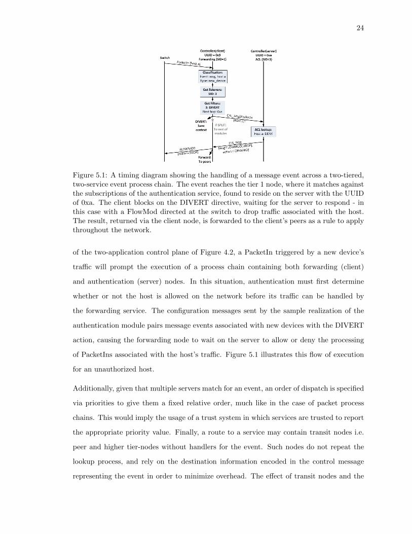
5.1. A timing diagram showing the handling of a message event across a two-
tiered, two-service event process chain. The event reaches the tier 1 node,
where it matches against the subscriptions of the authentication service,
found to reside on the server with the UUID of 0xa. The client blocks on
the DIVERT directive, waiting for the server to respond - in this case with
a FlowMod directed at the switch to drop traffic associated with the host.
The result, returned via the client node, is forwarded to the client’s peers as
a rule to apply throughout the network. . . . . . . . . . . . . . . . . . . . . 24
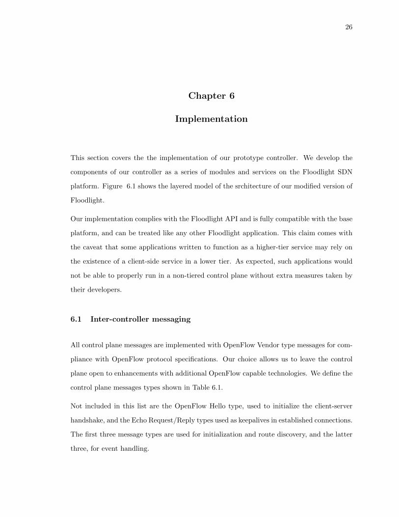
6.1. The modifications made to Floodlight so that it can function as a node in
the heterogeneous hierarchical control plane. The shaded boxes indicate our
extensions, which include the remote event dispatcher (a module), client and
server-facing channel handlers, and the representations of client and server
nodes associated with this node. . . . . . . . . . . . . . . . . . . . . . . . . 27
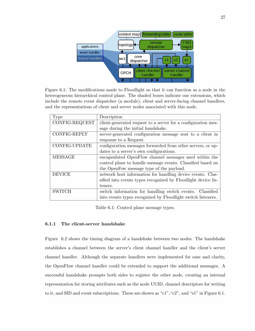
6.2. The client-initiated handshake between two controllers. The OpenFlow Hello
message is used with the controller UUID in place of a switch DPID. Simi-
larly, the Config-Request is a renamed OpenFlow Features Request message.
The Config-Reply and -Update are variable-length messages containing pro-
cess chain configurations. The reception of the Reply indicates a successful
handshake, after which keepalives and further Update messages may be ex-
changed. . . . . . . . . . . . . . . . . . . . . . . . . . . . . . . . . . . . . . . 28
6.3. The client escalation process chain. . . . . . . . . . . . . . . . . . . . . . . . 30
6.4. The server and peer process chains. . . . . . . . . . . . . . . . . . . . . . . . 31
6.5. The client return path process chain. . . . . . . . . . . . . . . . . . . . . . . 31
vii
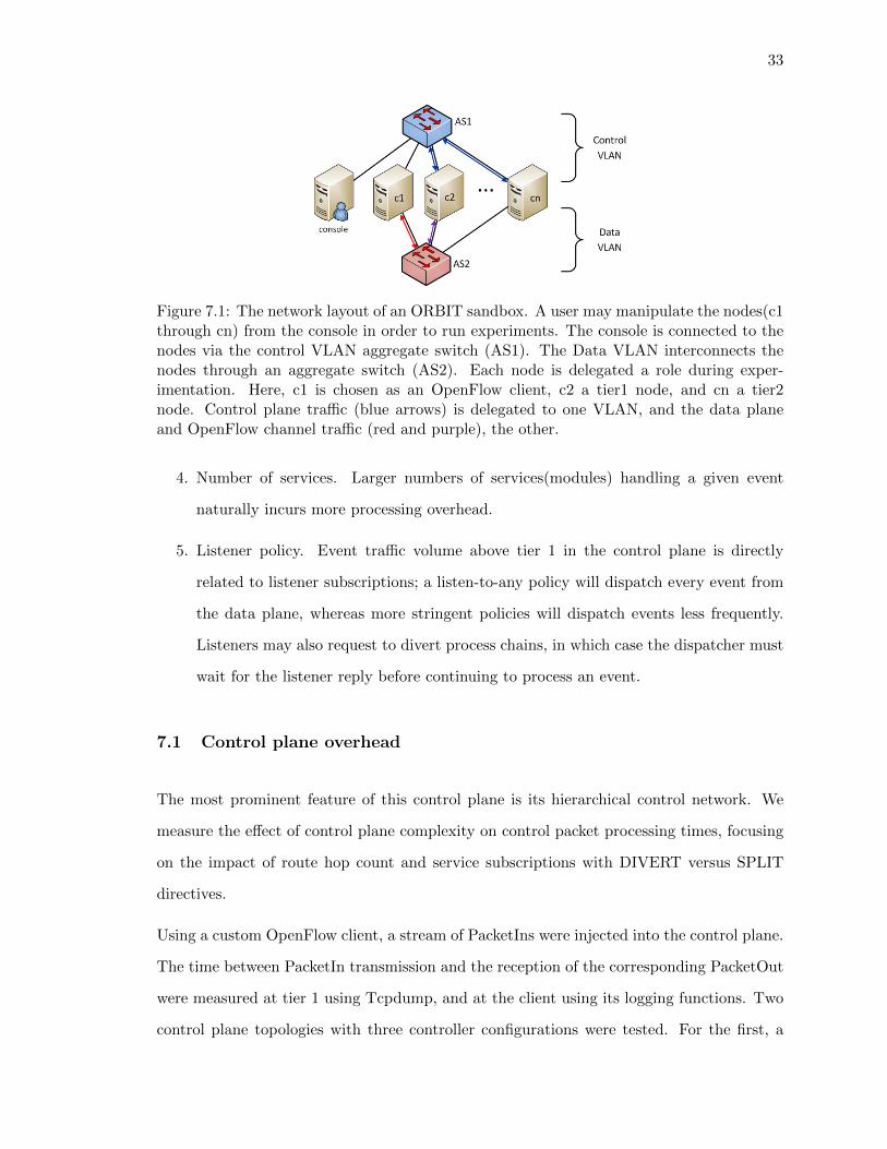
7.1. The network layout of an ORBIT sandbox. A user may manipulate the
nodes(c1 through cn) from the console in order to run experiments. The
console is connected to the nodes via the control VLAN aggregate switch
(AS1). The Data VLAN interconnects the nodes through an aggregate switch
(AS2). Each node is delegated a role during experimentation. Here, c1 is
chosen as an OpenFlow client, c2 a tier1 node, and cn a tier2 node. Control
plane traffic (blue arrows) is delegated to one VLAN, and the data plane and
OpenFlow channel traffic (red and purple), the other. . . . . . . . . . . . . 33
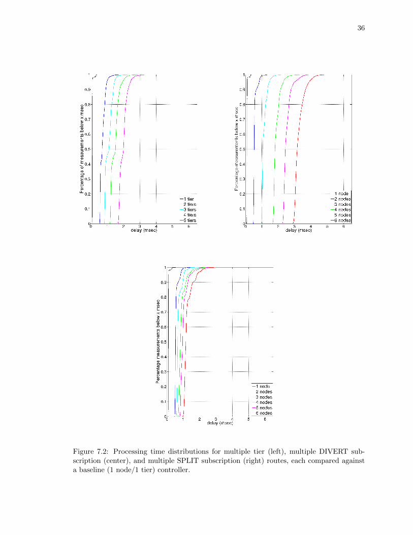
7.2. Processing time distributions for multiple tier (left), multiple DIVERT sub-
scription (center), and multiple SPLIT subscription (right) routes, each com-
pared against a baseline (1 node/1 tier) controller. . . . . . . . . . . . . . . 36
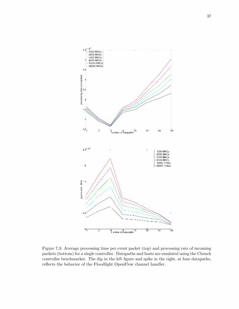
7.3. Average processing time per event packet (top) and processing rate of in-
coming packets (bottom) for a single controller. Datapaths and hosts are
emulated using the Cbench controller benchmarker. The dip in the left fig-
ure and spike in the right, at four datapaths, reflects the behavior of the
Floodlight OpenFlow channel handler. . . . . . . . . . . . . . . . . . . . . . 37
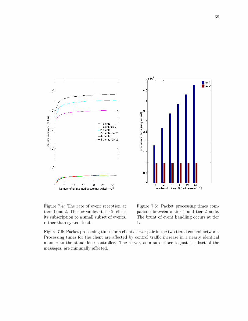
7.4. The rate of event reception at tiers 1 ond 2. The low vaules at tier 2 reflect
its subscription to a small subset of events, rather than system load. . . . . 38
7.5. Packet processing times comparison between a tier 1 and tier 2 node. The
brunt of event handling occurs at tier 1. . . . . . . . . . . . . . . . . . . . . 38
7.6. Packet processing times for a client/server pair in the two tiered control
network. Processing times for the client are affected by control traffic increase
in a nearly identical manner to the standalone controller. The server, as a
subscriber to just a subset of the messages, are minimally affected. . . . . . 38
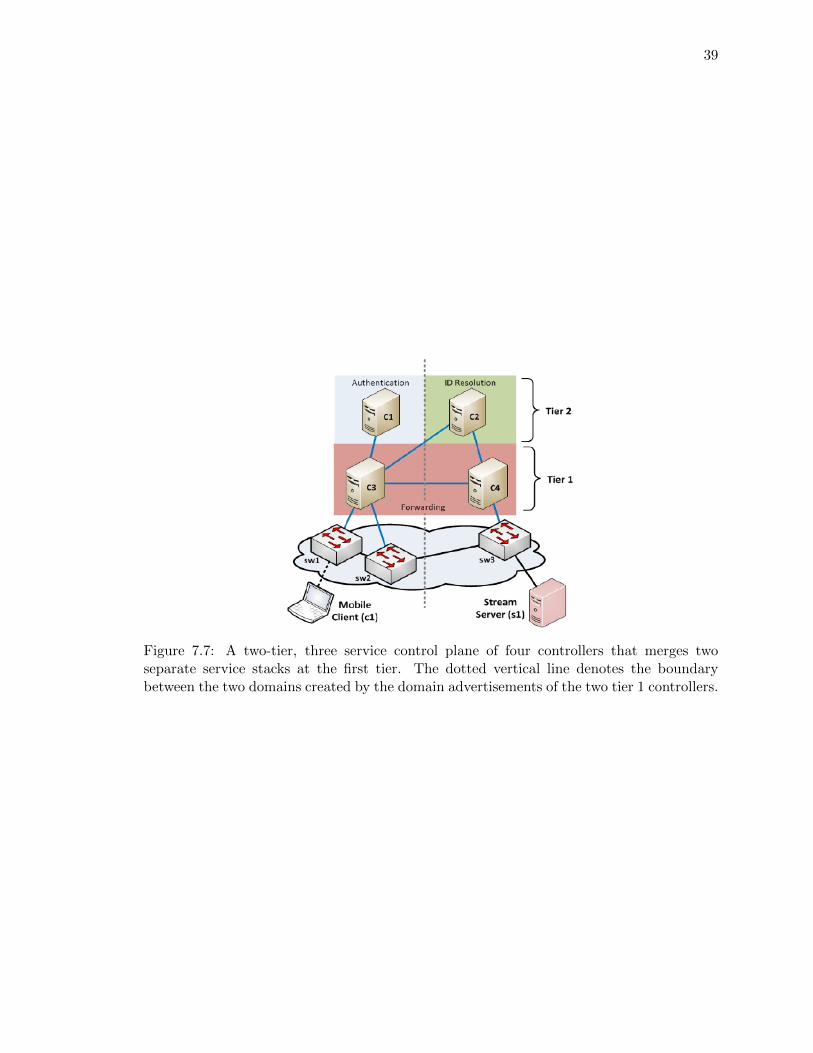
7.7. A two-tier, three service control plane of four controllers that merges two
separate service stacks at the first tier. The dotted vertical line denotes the
boundary between the two domains created by the domain advertisements of
the two tier 1 controllers. . . . . . . . . . . . . . . . . . . . . . . . . . . . . 39
viii
1
Chapter 1
Introduction
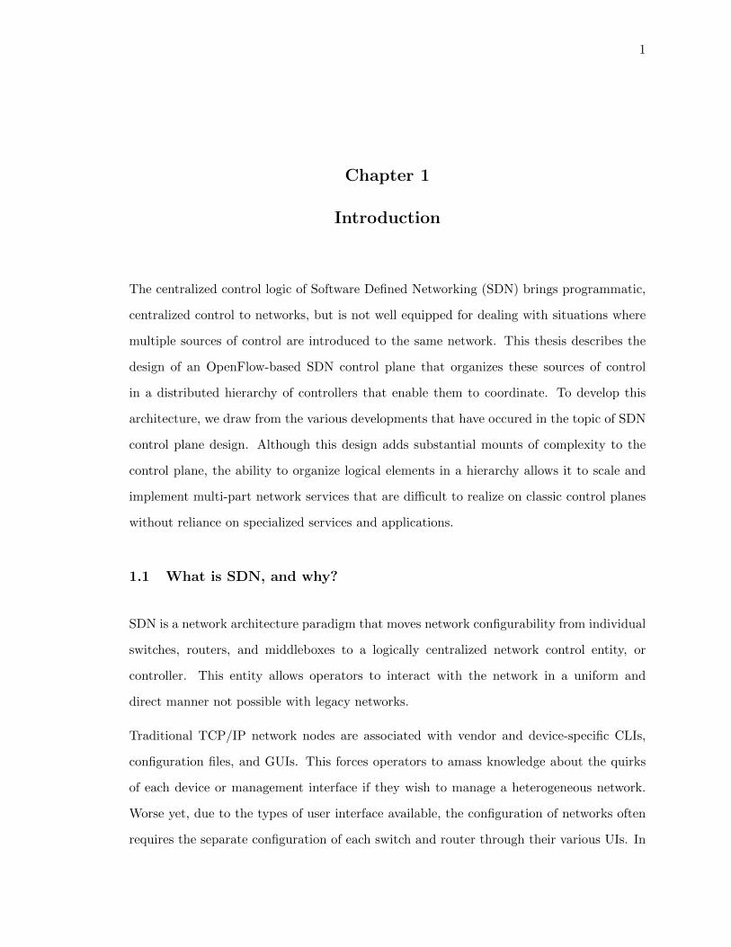
The centralized control logic of Software Defined Networking (SDN) brings programmatic,
centralized control to networks, but is not well equipped for dealing with situations where
multiple sources of control are introduced to the same network. This thesis describes the
design of an OpenFlow-based SDN control plane that organizes these sources of control
in a distributed hierarchy of controllers that enable them to coordinate. To develop this
architecture, we draw from the various developments that have occured in the topic of SDN
control plane design. Although this design adds substantial mounts of complexity to the
control plane, the ability to organize logical elements in a hierarchy allows it to scale and
implement multi-part network services that are difficult to realize on classic control planes
without reliance on specialized services and applications.
1.1 What is SDN, and why?
SDN is a network architecture paradigm that moves network configurability from individual
switches, routers, and middleboxes to a logically centralized network control entity, or
controller. This entity allows operators to interact with the network in a uniform and
direct manner not possible with legacy networks.
Traditional TCP/IP network nodes are associated with vendor and device-specific CLIs,
configuration files, and GUIs. This forces operators to amass knowledge about the quirks
of each device or management interface if they wish to manage a heterogeneous network.
Worse yet, due to the types of user interface available, the configuration of networks often
requires the separate configuration of each switch and router through their various UIs. In
2
addition, the UI of a single switch only gives an administrator a view of the switch’s state,
rather than that of the whole network. This leaves network-wide behaviors to be defined
by side-effects resulting from the behaviors of each device.
Despite being cumbersome and very error-prone, this per-device approach of network config-
uration is usually the only method available to an administrator. Enterprise solutions[4, 17]
that give administrators the ability to centrally manage and configure networks do exist,
with the caveat that the network must be built with the products of the vendors offering
these frameworks. Standards such as Simple Network Management Protocol (SNMP)[41]
have attempted to provide open solutions for uniform network management interfaces; Yet,
the interpretation of MIBs (e.g. the availability and modifiability of various device pa-
rameters) vary greatly from vendor to vendor, again leading to the need of vendor (or
product)-specific knowledge.
SDN-based architectures separate the network into a control plane, data plane, and a control
channel that connects the two. The control plane is a logically centralized entity that houses
the functionalities of the network stack, along with managerial and programmatic interfaces
that let operators configure the control plane. The data plane is a collection of simplified
traffic forwarding elements, or switches, whose actions are determined by the contents of the
flow table. The flow table maps patterns in network packet headers to actions to take on
packets that match them, such as drop, flood, or forward out of a chosen port. The control
plane dictates the behavior of the data plane by manipulating the contents of the flow table
via the control channel. Within the channel, a network control protocol translates between
the control plane logic and the “instruction sets” that switches can install as flow table
rules.
In other words, SDN takes a switch and decouples the logic from the switch fabric, and has
the former control the behavior of the latter over a communications link. The decoupled
logic is then capable of managing not just one, but all of a network’s switches, treating them
as one logical entity. Management of such networks is then reduced to defining control plane
functions that configure this entity. In sum, networks built according to the SDN paradigm
provide uniformity via an interface that takes the form of a network control protocol, and
3
Figure 1.1: A generic representation of an SDN-based network, with the components labeled.The controller can be described as a collection of applications, or event handlers for thevarious types of control channel messages it receives from the data plane. The messages areformatted according to the control protocol within the channel.
network-scope management via a logically centralized controller that configures the network
fabric with the said protocol.
1.2 SDN in practice
In practice, the control plane is implemented by way of a network operating system (NOS),
and the network functions and services as a series of applications within the NOS. The NOS
may be physically singular or distributed, running as a process within one or more servers,
also referred to as controllers. The data plane elements, or datapaths, are SDN-capable
switches and routers connected to their controller(s) via a network link for the control
channel. Figure 1.1 shows an example of a SDN-based network.
1.3 Open SDNs and the OpenFlow protocol
Of the categories of SDN currently available, our focus resides on the class of SDN known
as open SDN. Open SDNs use openly standardized control protocols, and are available
in the forms of open source controller and protocol library implementations. Specifically,
we are interested in open SDNs that leverage the OpenFlow[27] protocol. OpenFlow is
a network control protocol openly standardized and maintained by the Open Networking
Foundation[28]. OpenFlow is notable for the sizable amount of academic and industrial
4
support it has garnered. The wide availability of controller platforms[13, 10, 22, 38, 44, 40],
hardware and software switches[14, 30, 25] supporting the protocol, and testing tools[36,
26, 32], makes OpenFlow appealing to SDN research and development. In fact, one may
even argue that the the concept of SDN has become popularized by the development of
OpenFlow, and that the two are nigh synonymous in the case of open SDN.
In addition to its availability, live deployments such as the GENI campus trials[12] have
demonstrated the practicality of OpenFlow networks. This has led to work focusing on the
enhancement OpenFlow networks for improved utility. This work aims to serve as both a
survey of the various improvements proposed for these networks, as well as an attempt to
introduce our own. Specifically, we focus on the development of various OpenFlow control
plane architectures, and introduce our own control plane design, complete with a prototype
implementation.
1.4 Organization of this thesis
We begin with an overview of currently available OpenFlow control plane architectures. We
follow by discussing the various shortcomings of the classic controller, and the developments
found in more recent control platforms aimed at mitigating some of these issues, in Section 2.
We then move our focus to the less-frequently discussed subject of service placement in the
control plane, and introduce the notion of the hierarchical controller. In Section 3 , we
then take a look at the Floodlight, a widely-adopted controller platform that is the basis
for the implementation of our control plane, delving into the details of a precursory project
that adds partial supports for FlowVisor-like virtualization to Floodlight. This discourse
is followed by Sections 4 through 7, the design, implementation, and evaluation of our
heterogeneous hierarchical control plane. We close with future works and finishing remarks
in Section 8.
5
Chapter 2
(Open) SDN control planes and trends
OpenFlow networks realize the SDN paradigm by logically centralizing the control plane
intelligence into controllers. The controllers orchestrate simplified network elements, known
as datapaths or OpenFlow switches. The flow tables of an OpenFlow switch match on
Ethernet and TCP/IP header fields, allowing the switch to drop, forward, and rewrite
packet header contents upon match. Datapaths handle network traffic by consulting their
flow tables. A miss in the flow table prompts a switch notify the controller with a PacketIn
message, causing the controller to generate the appropriate flow rules for the packet in the
forms of PacketOut and FlowMod messages. The full protocol specification is made publicly
available at [27].
The architecture of the control plane has been a point of interest since its beginnings with
the reference design[31] featuring a single physical controller. We discuss the progressions in
control plane design in this section, focusing on the shortcomings that have been identified
in open controller implementations.
2.1 The single-controller control plane.
Many controller designs have assumed that a network would only have one instance of a con-
troller running in the control plane. This assumption has allowed developers to implement
simplified, physically centralized controllers. While simple and easy to manage, a single
controller architecture is a detriment to a network’s scalability, resilience, and performance.
In addition to being a single point of failure, a network’s processing power becomes limited
to that of the the controller hardware. Regardless of CPU load, a switch located at the
6
edge of a large network may be far enough from a central controller for it to suffer from
flow setup delays, leading to more dropped packets[43].
To introduce redundancy measures, OpenFlow protocol specifications have allowed switches
to maintain a list of failover controllers. More recent protocol revisions (>v.1.2.0) add
controller-side master election schemes that enable them to coordinate with switches and
other controllers for a smooth, automated failover from a primary controller to a hot
standby[27].
Many current controller platforms follow the single-controller architecture, albeit with en-
hancements such as parallelization[22, 13, 1]. However, physical centralization still imposes
a limitation on network size and utilization, leaving the question of scalability open.
2.2 Distributed control planes.
A single-controller control plane with perfect uptime may still become a bottleneck with
sufficient CPU loads or a large enough data plane. Distributed control platforms such
as [43, 18, 40, 42, 20] disperse multiple synchronized clones of controllers throughout the
control plane to scale to larger networks and traffic loads. In addition to distributing the
workload on each instance, distributed control planes also reduce flow setup latencies by
reducing the distance between any given switch and the closest available controller. Better
still, the presence of multiple copies of a controller leads to a model that naturally includes
redundancies that failover mechanisms can take advantage of. Figure 2.1 shows a general
organization of a distributed control plane.
The few documented examples of this category of control plane are formed from con-
trollers enhanced by scalable databases and group coordination/synchronization services.
Hyperflow[43], an application for NOX, employs a pub-sub mechanism synchronized over
the WheelFS distributed filesystem to allow multiple NOX instances to share state. Onix[18]
employs a combination of a replicated database and an eventually consistent, one-hop DHT
for synchronization and the Apache Zookeeper process coordination framework for coordina-
tion. ONOS[20], an open platform inspired by Onix and derived from Floodlight, follows a
7
Figure 2.1: The datapaths of a distributed control plane may not necessarily connect to thesame controller. The controllers operate on a shared view of the network with the aid ofdistributed mechanisms, keeping the data plane’s state consistent.
similar approach using the Cassandra database backed by Titan distributed graph database
for eventual consistency, and Zookeeper for coordinated failover. Other platforms focusing
on resilience[47] permit dynamic additions and removals of controllers using address re-
assignment, made possible through a framework for running single-controller platforms in
clusters.
In general, distributed control planes are assocated with proprietary platforms like Onix,
Helios, and Cardigan, or research-stage platforms like HyperFlow, and are not quite acces-
sible for use. While ONOS is the first distributed framework formally intended for open
source distribution, it is still under heavy development and is not readily available at the
time of this writing.
2.2.1 Distributed control planes - what is missing?
Being logically uniform, general distributed control planes are nto suited to handling the
interaction of network stacks, or network stacks containing applications with different scop-
ing requirements for operation. A large issue associated with the coexistence of network
stacks is the misconfiguration of datapaths due to conflicting flow installations by two
service/network stacks[35]. Even with the scalablity and resilience of a distributed con-
trol plane, individual controllers may still become bottlenecks if overloaded by frequently-
invoked applications, or if processing for those applications prevents the function of others.
8
Control planes have so far relied on specialized frameworks, applications, and protocol
enhancements in order to handle these situations. Network virtualization frameworks such
as FlowVisor[39] make the coexistence of conflicting services possible by cordoning off each
controller onto its own piece, or slice, of network that only it can configure. However,
controllers within these virtualized slices are unaware of the presence of others, and therefore
are not capable of active interaction. Network compilers such as Nettle[46], NetCore[24],
and PANE[8], and derivative frameworks such as HFT[7] have a different approach, using
conflict resolution schemes to resolve flow conflicts within the same logical network before
installing them in the data plane. DIFANE[49] and DevoFlow[5] propose a ”division-of-
labor” scheme between the data plane and a controller, where local-scope, high-frequency
events are handled at the switch, and network-wide tasks, such as route setup and load
balancing, are handled by the controller. These techniques require the re-intoduction of
control plane functions to the data plane, limiting their utility in established OpenFlow
networks. Finally, while applications such as SDN-IP[21] and SDX[6] offer ways to peer
SDNs with IP networks, there is no established formula for a seamless interface between
the control planes of adjacent networks.
We note that some of the cases above may be reformulated in terms of controllers that
directly interact with one another. For example, Kandoo[48] emulates the intelligent data
plane of DevoFlow and DIFANE by organizing a two-tiered hierarchy of controllers, in
which the lower tier handles the local flows that would be handled by the switches, and
the higher tier maps to the centralized controller. Likewise, a virtualized network may be
viewed as a collection of controllers, with FlowVisor a resource isolation application running
as a specialized controller. We refer to control planes that mix controllers with different
functions as heterogeneous control planes, described next.
2.3 Heterogeneous control planes
Formally, we consider heterogeneous control planes to be a class of distributed control plane
that breaks down network stacks and applications into functional subcomponents. Each
subcomponent is hosted on a controller that possesses 1) the appropriate logical view of the
9
data plane and 2) the interfaces to the controllers hosting subcomponents of its interest.
We consider this architecture to be heterogeneous, since, unlike the frameworks in which
the controllers are clones, any two controllers from this control plane may host completely
separate functionalities. A marked difference in the operation of the heterogeneous control
plane is the involvement of multiple controllers in configuring one switch, with controllers
interacting with others to complete the service set required for a properly behaving data
plane. Like in Kandoo, the division of labor according to scope adds a level of functionality
not available in classic control planes.
Heterogeneous control planes add both flexibility and scalability to a control plane in ways
not possible with other architectures. The ability to let controllers communicate enables
collaboration and coordination of network stacks and services that would otherwise conflict,
or have to be treated as specialized frameworks because they do not uniformly centralize
the control plane’s services. We discuss this control plane architecture in depth in Section 4,
our introduction to the heterogeneous control plane design.
10
Chapter 3
Open SDN Controller Architecture
Open SDN has received much attention from the network research community, and has
benefited from various advancements in control plane architectures and controller technolo-
gies. As a result, currently available open controller platforms, while not fully-featured or
bleeding-edge, are extensible for research and development purposes, and capable as control
plane deployments. Importantly, the former allows open SDN platforms to be used as a
basis for enhanced architectures or experimental network services. Our discussion of open
platforms focuses on Floodlight, the platform upon which our control plane prototype is
based.
Floodlight is a Java-based Open SDN controller platform with a module-based, extensible
API aimed at SDN service development. As a widely adopted open-sourced core of a
commercial-grade controller product[2], Floodlight is suitable as both a stable control plane
deployment and a development platform. We first introduce our model for the layered SDN
control plane architecture, and follow with Floodlight architecture, introducing concepts
and terminology referenced in the proceeding sections.
3.1 The layered control plane model
We recognize the control plane to have three distinct layers:
• control channel handler : The control channel handler interfaces the control channel,
and is directly responsible for sending and receiving control packets and listening for
incoming connections from the data plane. In open SDNs, the channel handler includes
facilities to encode and decode OpenFlow messages, and may directly implement the
11
controller-side OpenFlow handshake for establishing connections from datapaths.
• event dispatcher : The event dispatcher translates between control channel messages
and controller-internal events that can be interpreted by the NOS and its services,
and serves as an event dispatch/scheduling mechanism that passes events to various
interested services.
• applications : Applications implement the various services that add functionality and
usability to the controller. These functions range from network stack functions such
as topology mapping and packet forwarding to interfaces such as GUIs and RESTful
APIs. Applications may also provide specialized functions such as synchronization
elements of distributed controllers.
This layered organization has been verified to be applicable to the code-bases of NOX,
FlowVisor, and, as shown in the next section, Floodlight.
3.2 Floodlight system architecture
Floodlight defines its basic units of functionality in the form of Java modules. At its core,
a module is characterized by the implementation of a Java interface that allow it to be
recognized, and if selected for usage, loaded, by Floodlight’s module loading system at
startup. Functionally, modules:
• handle events to generate OpenFlow messages and/or additional events
• expose services to provide resources for other modules
• utilize services to provide user and programmatic interfaces
or any combination thereof. Ultimately, a module directly or indirectly generates asyn-
chronous OpenFlow messages that influence the behavior of the data plane, or provides a
means for an operator to interact with the network.
12
Floodlight identifies two types of modules, core and application modules. The former pri-
marily implements low-level NOS components including the channel handler, event dis-
patcher, and the API atop which application modules are developed. The latter imple-
ments the services that implement Floodlight’s controller functions i.e. the application
layer components. [9] documents the modules that comprise the base install of Floodlight.
3.2.1 Floodlight core components
Floodlight currently recognizes three categories of events:
1. Message events : The reception of various OpenFlow messages. Message events are
further classified by OpenFlow message type field values.
2. Switch events : The connection, disconnection, and status changes of datapaths.
3. Device events : Various state changes in network hosts such as motion and IP address
change.
In Floodlight, the OpenFlow channel handler and dispatcher are formed by two core mod-
ules, FloodlightProvider and DeviceManager. In specific, FloodlightProvider listens on the
OpenFlow channel to generate message and switch events, and the DeviceManager sub-
scribes to FloodlightProvider’s message events to generate device events. The rest of the
modules function as various event listeners to these two modules. These include the core
modules that would be categorized as applications in the above model, including in-memory
storage, topology discovery, and a service allowing modules to expose REST APIs.
In addition to modules, each entity in the data plane that the controller learns about is
given an internal representation. In the case of switches, the representation serves as a
dispatch point for messages destined for the switch. These switch constructs serve as the
outbound components of the event dispatcher.
13
Figure 3.1: The internals of Floodlight, shown in context to a network of three switches,with modules for topology discovery, firewall, and routing. The arrows represent the flowof an event across a packet process chain involving the three modules. FloodlightProvideris split into to the core dispatcher and the OpenFlow channel handler. Device manager andthe representations of tracked hosts are omitted in the interest of clarity.
3.2.2 Floodlight application modules
Modules that implement services that Floodlight’s base functions do not rely upon are
categorized as application modules. This includes the forwarding engine, which subscribes
to the core service for PacketIns and produce flow rules to be written back to the switches
as PacketOuts and FlowMods.
3.2.3 The packet process chain
An event being processed is passed along an associated set of modules in a packet process
chain. Typically, the process chain involves modules that generate events or information
required by subsequent modules. In order to meet these dependencies, the dispatcher sees
to it that a given set of modules with interdependencies will always be invoked in the same
order. In addition to this fixed order, each event is associated with its own set of contexts,
shared amongst the modules participating in the process chain via an internal context map.
Figure 3.1 illustrates the key components to the Floodlight runtime with respect to the
layered model and the descriptions above.
14
Chapter 4
Hierarchical Heterogeneous Control Planes
This section is a detailed discussion of the hierarchical heterogeneous control plane, and the
various decisions made in its design. We begin the section with the motivation for developing
heterogeneous control planes. Next we present a general overview of the structure of our
control plane, and how it allows multiple services to coexist in the same network. We
note the implications that this approach has to the architectural design of the individual
controllers in the control plane, and follow by delving onto the details of the components
and functions needed to realize this design.
4.1 Motivation for Heterogeneous Control Planes
Current control planes do not deal well with deployments that do not uniformly centralize
their network logic. A network stack, run in one or more controllers as a set of applications,
typically assumes that it is the sole source of network control in a deployment. Several
situations break down this assumption, including:
• Shared networks. Multiple administration groups may configure various aspects of
a service-rich (inter)network. Each group’s task may involve configuring and main-
taining specific services in the form of servers or middleboxes, or portion of the in-
frastructure. In a different vein, multiple service providers may practice infrastruc-
ture sharing under regulatory pressure or to cut costs in infrastructure deployment
and maintenance[15]. Particularly, in active infrastructure sharing, multiple service
providers share network elements such as switching, routing, and other telecommuni-
cations equipment, and individually provide support to their customer bases. Notably,
15
Figure 4.1: A generic representation of a hierarchical, heterogeneous control plane with threetiers and three categories of services, and two peer links. The client and server relations arelabeled with respect to node B1’s perspective.
there is interest for these providers to allow their customers to interact with one an-
other to increase service utilization. In these cases, each administrative group or
service provider may wish to maintain their own controllers, and in the latter case,
have them coordinate with the controller for the shared infrastructure.
• Heterogeneous networks. Modern networks are built with a mixture of technologies
with various properties and feature sets that must coordinate seamlessly, such as
LANs comprised of a mixture of wired and wireless components, which frequently
require varying traffic handling and host admission schemes. In a different vein, service
providers with adjacent infrastructures may wish to negotiate the handling of other
customers with their primary providers e.g. different charging policies for roaming
or negotiating traffic routing. Both cases involve potentially disparate service stacks
that interact as collaborative peers.
• Large-scale global policies applying to multiple spheres of influence. Sufficiently large
networks, even those managed by a single group, will often be administered in pieces
but have global policy enforcement and/or services spanning the pieces. Universities
are often a setting for this type of configuration, with locally administered network per
building, department, or campus, and a university-wide access control and network
16
Figure 4.2: A two-service network stack run as a hierarchical control plane. In order for theservices to act as one, both tier1 forwarding services and the tier2 authentication servicemust coordinate. In this case, authentication “monitors” the full network for new hosts, andforwarding works at the switch level to forward traffic, hence the placement of the servicesin respective tiers.
configuration policies. A logical hierarchy of controllers, with a controller per locally
administered region, and a higher-tier controller with a global view of the network,
may be capable of realizing this management scheme.
As stated in section 2.2.1, there is no clear solution to handling these cases with classic SDN
networking models. However, as seen above, multiple controllers orchestrated to coordinate
with one another may make it possible to formulate these network configurations as SDN-
based networks. We propose that a heterogeneous control plane with a hierarchical structure
offers a general framework for building these non-classical OpenFlow deployments.
4.2 General functions and features
The standard control plane assumes that, under normal operation, all services that it hosts
belong to the same network stack, or service set. A service set typically takes the form of
a collection of applications or services.
This control plane organizes a group of controllers, or nodes, into a hierarchy, with each tier
containing one or more possibly interconnected controllers. The nodes of each tier behave
as clients to the nodes in the tier above, and servers to the nodes in the tiers below. The
client-server relationship stems from the escalation of events from low tiers to high, with
17
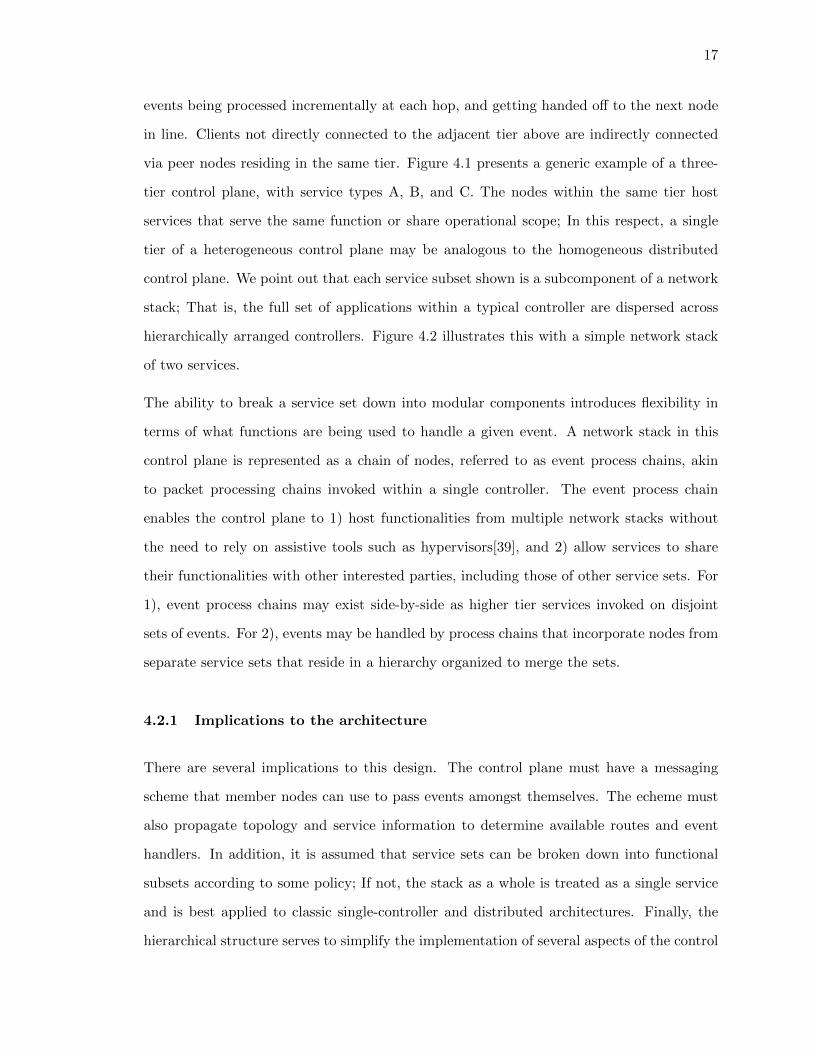
events being processed incrementally at each hop, and getting handed off to the next node
in line. Clients not directly connected to the adjacent tier above are indirectly connected
via peer nodes residing in the same tier. Figure 4.1 presents a generic example of a three-
tier control plane, with service types A, B, and C. The nodes within the same tier host
services that serve the same function or share operational scope; In this respect, a single
tier of a heterogeneous control plane may be analogous to the homogeneous distributed
control plane. We point out that each service subset shown is a subcomponent of a network
stack; That is, the full set of applications within a typical controller are dispersed across
hierarchically arranged controllers. Figure 4.2 illustrates this with a simple network stack
of two services.
The ability to break a service set down into modular components introduces flexibility in
terms of what functions are being used to handle a given event. A network stack in this
control plane is represented as a chain of nodes, referred to as event process chains, akin
to packet processing chains invoked within a single controller. The event process chain
enables the control plane to 1) host functionalities from multiple network stacks without
the need to rely on assistive tools such as hypervisors[39], and 2) allow services to share
their functionalities with other interested parties, including those of other service sets. For
1), event process chains may exist side-by-side as higher tier services invoked on disjoint
sets of events. For 2), events may be handled by process chains that incorporate nodes from
separate service sets that reside in a hierarchy organized to merge the sets.
4.2.1 Implications to the architecture
There are several implications to this design. The control plane must have a messaging
scheme that member nodes can use to pass events amongst themselves. The echeme must
also propagate topology and service information to determine available routes and event
handlers. In addition, it is assumed that service sets can be broken down into functional
subsets according to some policy; If not, the stack as a whole is treated as a single service
and is best applied to classic single-controller and distributed architectures. Finally, the
hierarchical structure serves to simplify the implementation of several aspects of the control
18
plane such as bootstrapping, routing and control message propagation, and setting a clear
global policy on the partitioning scheme of service sets. We discuss these functions and
components in Section 5.
4.2.2 Related works
Architectures in which varying controllers coexist on a single network have been rarely
addressed outside of the topic of network virtualization. However, we acknowledge that the
design of this control plane is influenced by several prior works.
FlowVisor[39] is a specialized controller that serves as a virtualization layer between the data
plane and multiple, functionally different controllers by overwriting control message contents
to present a controlled portion of network resources to each controller. Save specifically
configured mirror slices with read-only access to other slices, controllers behind a FlowVisor
are largely unaware of one another.
Kandoo[48] is a hierarchical control plane that separates its service set into two tiers. Al-
though closest to our architecture of interest, Kandoo does not allow controllers within a
tier to communicate directly with one another, and limits usage of the second tier to services
requiring a global network view.
Onix[18] is capable of limited federated operation, in which two Onix instances may share
summarized views of the networks that they have control over. This sharing of informaton
is contained to Onix instances under the same authority, and serves to allow the compact
representation of massive data planes within the Onix NIB.
19
Chapter 5
Control plane internals
The following sections describe the various components and mechanisms that provide the
features necessary for implementing the heterogeneous hierarchical control plane. We begin
with control-plane scale functions that enable the controllers to coordinate in event process
chains.
Before we begin, we note that the subject of network view synchronization is omitted, as
it is well-discussed in the study of classical distributed control planes. We assume that any
nodes requiring synchronization can use the proven methods of these control planes. In
addition, we assume that this control plane would be given a dedicated control network
physically separate from the data plane. This allows us to avoid the bootstrapping issue of
needing to setup flows for control traffic.
5.1 Inter-controller (Control-plane-level) functions
Each node in the control plane is identified by three attributes - 1) A unique node identifier
(UUID), a value assigned to each node to serve as an address in the control plane, 2) A
service identifier (SID), a value assigned to the services hosted at a node, and 3) Event
subscriptions, the set of network events that a service is capable of handling and that a
server will subscribe to a client for.
UUIDs provide clients with an addressing scheme that allows them to build route tables
mapping next-hop UUIDs to SIDs. Similarly, event subscriptions are used by clients to
determine which known servers are capable of handling which events, and are used to
build dispatcher mappings between services and the events that may be sent to them for
20
handling. This mapping is used by clients to determine which services are able to handle
a given event; Once this is known, the route table is inquired for the best next hop(s) to
reach the destination service(s). This mechanism is described next.
5.1.1 Controller Initialization and Discovery
Controllers must be able to find one another in order to form the control plane hierarchy.
The client-server classification of nodes is used to bootstrap the process. Upon startup, a
server begins listening for client connetions on a pre-established port, with clients periodi-
cally attempting to connect to them. For the purpose of simplicity, our implementation of
the client is supplied with a list of servers to which it must attempt to connect to. The client
attempts a limited number of reconnects if its server is initially unavailable. A successful
connection attempt is followed by a handshake, in which the server informs the client of its
event subscriptions. Peer links are bidirectional, containing two links connecting both ends
as clients of the other.
A self-organizing heirarchy is an appealing alternative to the approach of manually config-
ured clients. Controllers may make use of services similar to portmap[37] or UPnP [45] to
facilitate coordination. The former requires all controllers to contact a centralized service
that maintains a map of all available services to their locations; the latter relies on discov-
ery messages broadcast on known ports by both control point (client) and UPnP device
(server).
In the case of automatic discovery, the time required for all controllers to discover one
another becomes sensitive to the method of discovery. In the case of UPnP-like usage of
broadcast, advertisements are repeated at randomly spaced intervals[45]. A careful choice
of interval would be required to prevent broadcast storms and to ensure minimal startup
time of the full control plane.
21
5.1.2 Route and service propagation
Route and server event subscription information is propagated on the basis of sucessful
connection establishment, e.g. as new connections are made between clients and servers.
New connections prompt servers to send their own event subscriptions, along with any that
they have heard from higher tiers, to the client as configuration messages. The recipient of
the message, along with those connected to it as peers and clients, continue to propagate
the messages down towards the data plane.
As shown in Figure 4.1, each tier may have multiple links to their adjacent tiers. Given
a client and a set of servers, it is best to choose the shortest paths to each service in the
interest of limiting overhead. Configuration messages encode not only event subscriptions,
but also the UUID, SID, and the distance of the server node from the current recipient of
the message. This allows recipients to build their routing tables using these propagated
messages. For the sake of simplicity, we implement a simplified, RIP-like distance vector
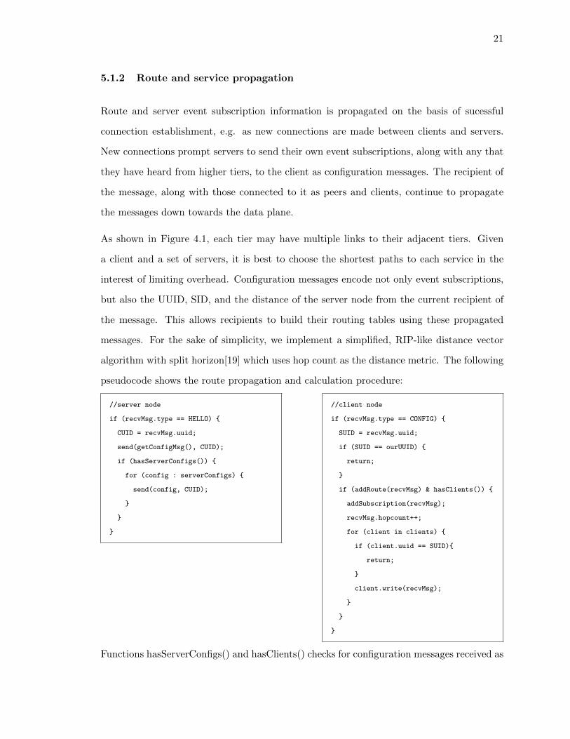
algorithm with split horizon[19] which uses hop count as the distance metric. The following
pseudocode shows the route propagation and calculation procedure:
//server node
if (recvMsg.type == HELLO) {
CUID = recvMsg.uuid;
send(getConfigMsg(), CUID);
if (hasServerConfigs()) {
for (config : serverConfigs) {
send(config, CUID);
}
}
}
//client node
if (recvMsg.type == CONFIG) {
SUID = recvMsg.uuid;
if (SUID == ourUUID) {
return;
}
if (addRoute(recvMsg) & hasClients()) {
addSubscription(recvMsg);
recvMsg.hopcount++;
for (client in clients) {
if (client.uuid == SUID){
return;
}
client.write(recvMsg);
}
}
}
Functions hasServerConfigs() and hasClients() checks for configuration messages received as
22
a client, and the existence of clients for a server-role node, respectively. Route calculation
is done in addRoute(), which returns true for new SID:UUID mappings or those with a
smaller hop count.
A distinction of this procedure is that only the servers emit route information (as configu-
ration messages), and when they do, only along the enforced downward path i.e. towards
the data plane. The effect of this limited route advertisement propagation is essentially to
produce minimum spanning trees rooted at the control plane services.
5.2 Context preservation
Once the control plane enters operating state, a node’s ability to preserve the context of a
event being handled across the multiple hops in an event process chain becomes important.
Any server in an event process chain may generate a return message aimed at the client
that had initiated the process chain. In order for the message to be properly returned to
the client, each server in the process chain must be able to identify the client that it had
received the event from, so that it may route the message back down the same path. In
other cases, a client may have to dispatch the same event to multiple servers, with services
requiring that the client wait for a return message before dispatching to the next server.
In this case, the client must be able to ’recall’ the next server in line after receiving the
return message, i.e. resume execution of a event process chain after a context switch. A
node maintains the notion of a transaction, and associates transaction identifiers (TXIDs)
with each event message in a transaction map that allows recovery of process chain state
information based on TXID.The saved state may include the UUID of the client responsible
for event dispatch, the event message, or a stack of next-hop servers to dispatch the event
to next.
The mechanism utilized is simlar to FlowVisor’s OpenFlow XID translator, which allows
FlowVisor to track OpenFlow conversations between its slices and the data plane. XID
translation stores the XID of a datapath-bound message and maps it to a newly gener-
ated XID value applied to the message. This enables FlowVisor to recover the old XID,
23
and therefore, the correct origin slice by inspecting the XID of a controller-bound message.
However, since XIDs may be modified by services, they cannot be used to reliably track con-
versations amongst controllers. We create the secondary transaction identifier as controller
constructs that are not affected by services.
5.3 Event process chain execution
In the initialization of client-server connections, the client’s local packet process chain is
essentially configured by its servers so as to incorporate, and properly execute, their services.
In addition to propagating them, a client node generates a map of services to server event
subscriptions from configuration messages. An OpenFlow message received at a first-tier
node is translated into an event, which is then used to search its map for entries that match.
Matches return one or more SIDs that can be used for route lookup for event dispatch. A
default behavior will be triggered when no matches are found. The current implementation
attempts to handle the event locally. A more sophisticated action may follow with a search
for servers capable of handling the event, such as with a broadcast of a request message on
a known port.
In addition to SIDs, an event subscription is associated with one or more actions that a
client should take when it finds a match:
• DENY: do not process the event further, returning a DROP FlowMod to the sender
switch if necessary.
• ALLOW: handle with local packet process chain, bypassing other event subscriptions
associated with the event
• DIVERT: dispatch the event to the service and halt the process chain until the service
returns a response
• SPLIT: dispatch the event to the service, and continue process chain execution
These directives are assigned by the server to its subscriptions in order to instruct the client
how to handle a matching event at its packet process chain. For example, given the example
24
Figure 5.1: A timing diagram showing the handling of a message event across a two-tiered,two-service event process chain. The event reaches the tier 1 node, where it matches againstthe subscriptions of the authentication service, found to reside on the server with the UUIDof 0xa. The client blocks on the DIVERT directive, waiting for the server to respond - inthis case with a FlowMod directed at the switch to drop traffic associated with the host.The result, returned via the client node, is forwarded to the client’s peers as a rule to applythroughout the network.
of the two-application control plane of Figure 4.2, a PacketIn triggered by a new device’s
traffic will prompt the execution of a process chain containing both forwarding (client)
and authentication (server) nodes. In this situation, authentication must first determine
whether or not the host is allowed on the network before its traffic can be handled by
the forwarding service. The configuration messages sent by the sample realization of the
authentication module pairs message events associated with new devices with the DIVERT
action, causing the forwarding node to wait on the server to allow or deny the processing
of PacketIns associated with the host’s traffic. Figure 5.1 illustrates this flow of execution
for an unauthorized host.
Additionally, given that multiple servers match for an event, an order of dispatch is specified
via priorities to give them a fixed relative order, much like in the case of packet process
chains. This would imply the usage of a trust system in which services are trusted to report
the appropriate priority value. Finally, a route to a service may contain transit nodes i.e.
peer and higher tier-nodes without handlers for the event. Such nodes do not repeat the
lookup process, and rely on the destination information encoded in the control message
representing the event in order to minimize overhead. The effect of transit nodes and the
25
SPLIT and DIVERT directives on processing times of the control plane are discussed in
Section 7.
This mode of operation requires that all service-providing nodes be trusted to convey the
correct client configurations. We implement a crude mechanism to checking controller
role consistency during the handshake, with the assumption that fully fledged controller
authentication and link encryption methods may be applied with further effort.
26
Chapter 6
Implementation
This section covers the the implementation of our prototype controller. We develop the
components of our controller as a series of modules and services on the Floodlight SDN
platform. Figure 6.1 shows the layered model of the srchitecture of our modified version of
Floodlight.
Our implementation complies with the Floodlight API and is fully compatible with the base
platform, and can be treated like any other Floodlight application. This claim comes with
the caveat that some applications written to function as a higher-tier service may rely on
the existence of a client-side service in a lower tier. As expected, such applications would
not be able to properly run in a non-tiered control plane without extra measures taken by
their developers.
6.1 Inter-controller messaging
All control plane messages are implemented with OpenFlow Vendor type messages for com-
pliance with OpenFlow protocol specifications. Our choice allows us to leave the control
plane open to enhancements with additional OpenFlow capable technologies. We define the
control plane messages types shown in Table 6.1.
Not included in this list are the OpenFlow Hello type, used to initialize the client-server
handshake, and the Echo Request/Reply types used as keepalives in established connections.
The first three message types are used for initialization and route discovery, and the latter
three, for event handling.
27
Figure 6.1: The modifications made to Floodlight so that it can function as a node in theheterogeneous hierarchical control plane. The shaded boxes indicate our extensions, whichinclude the remote event dispatcher (a module), client and server-facing channel handlers,and the representations of client and server nodes associated with this node.
Type Description
CONFIG-REQUEST client-generated request to a server for a configuration mes-sage during the initial handshake.
CONFIG-REPLY server-generated configuration message sent to a client inresponse to a Request.
CONFIG-UPDATE configuration messages forwarded from other servers, or up-dates to a server’s own configurations.
MESSAGE encapsulated OpenFlow channel messages used within thecontrol plane to handle message events. Classified based onthe OpenFow message type of the payload.
DEVICE network host information for handling device events. Clas-sified into events types recognized by Floodlight device lis-teners.
SWITCH switch information for handling switch events. Classifiedinto events types recognized by Floodlight switch listeners.
Table 6.1: Control plane message types.
6.1.1 The client-server handshake
Figure 6.2 shows the timing diagram of a handshake between two nodes. The handshake
establishes a channel between the server’s client channel handler and the client’s server
channel handler. Although the separate handlers were implemented for ease and clarity,
the OpenFlow channel handler could be extended to support the additional messages. A
successful handshake prompts both sides to register the other node, creating an internal
representation for storing attributes such as the node UUID, channel descriptors for writing
to it, and SID and event subscriptions. These are shown as “c1”,“c2”, and “s1” in Figure 6.1.
28
Figure 6.2: The client-initiated handshake between two controllers. The OpenFlow Hellomessage is used with the controller UUID in place of a switch DPID. Similarly, the Config-Request is a renamed OpenFlow Features Request message. The Config-Reply and -Updateare variable-length messages containing process chain configurations. The reception of theReply indicates a successful handshake, after which keepalives and further Update messagesmay be exchanged.
All actions directed towards another node are done through these representations.
6.1.2 Client process chain configuration
The Config-Reply messages received at a client are compiled into match rules stored in the
forwarding table. Match rules are similar to switch flow table entries, in which a message’s
fields are associated with actions. Events are matched by Event category and subtype,
and for each subtype, the values of subtype-specific fields. Each rule is associated with
primary (PPC) and secondary packet process chain (SPPC) actions. The former describes
the dispatcher module’s interaction with other local modules, and the latter, the interaction
between multiple servers i.e. remote modules whose installed rules match the same event.
In addition to exact matches, the forwarding table maintains a hierarchy of events and
match fields to support wildcards e.g. “any device event” or “MAC address X for either
source or destination fields”. Servers can also subscribe to event triggers. Event triggers are
specific message events that have triggered the generation of another event. As mentioned
in Section 3, all non-message events are products of services handling message events. Event
triggers are useful for subscriptions rules such as “messages associated with Device addition
29
events”.
6.1.3 Event process chain execution
Whereas the base Floodlight controller has one primary packet process chain tied to the
core FloodlightProvider module, the nodes of this control plane have three:
1. Client escalation chain : dispatches events from the OpenFlow channel to the remote
dispatcher. The dispatcher compares the event to the entries in the forwarding table
to find interested servers, initiating a transaction for each to send (escalate) them the
event. The TXID map shown in Figure 6.1 is just for server s1; each server has its
own TXID map.
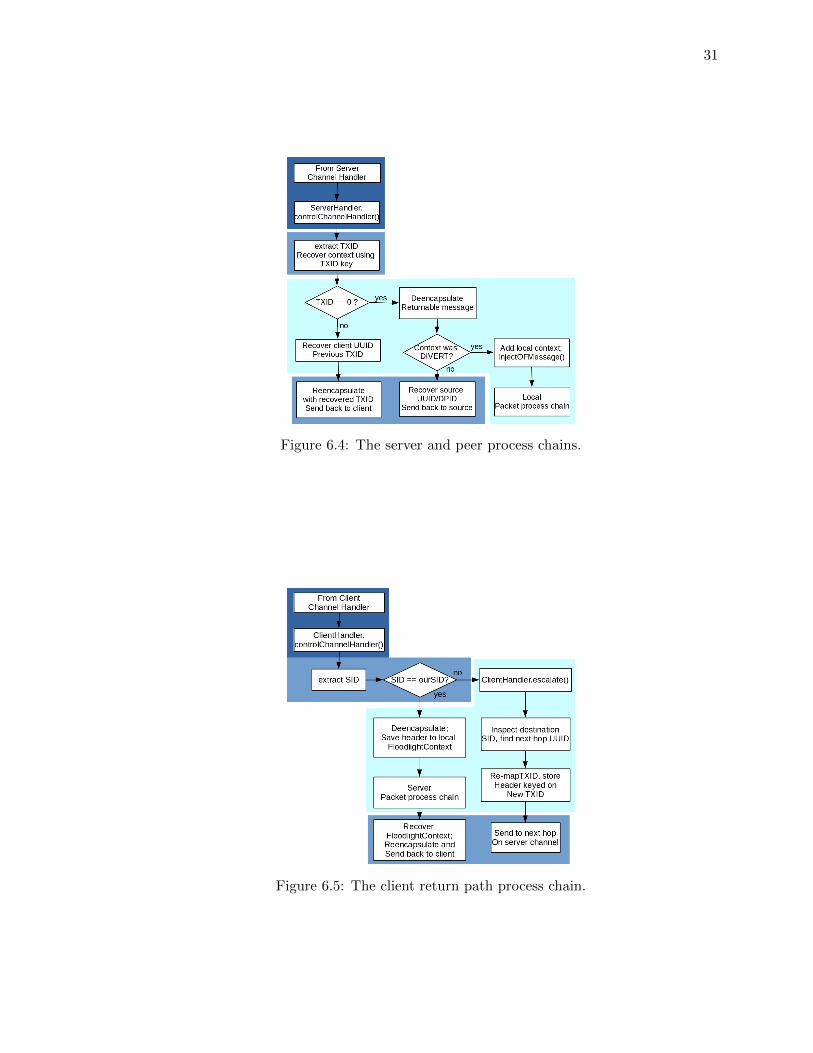
2. Server/peer chain : receives events from the client channel handler, handling them
if they were destined for the node, or escalating the event further if not. This is
determined by seeing if the destination SID and that of the node match. Escalation
at the peer relies on the destination SID in the control message header and a route
table lookup for the next hop to the SID. Message processing at the server process
chain involves saving the control message headers in order to reconstruct the header
when sending the reply mesage back. Each escalation re-maps the TXID to a new
value, much like FlowVisor’s XIDTranslater described in Section 5.2.
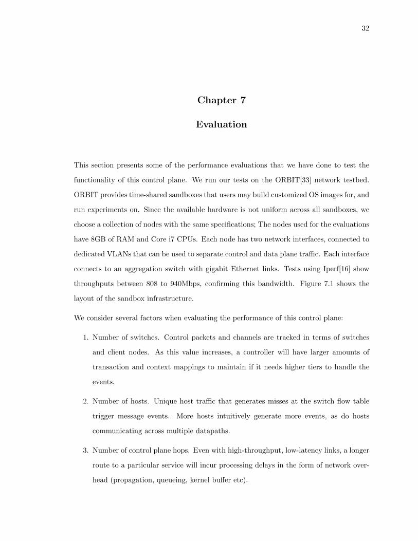
3. Client return chain : recieves server response messages from the server channel han-
dler, undoing the TXID translation to recover the stored process chain context. This
context is needed to either resume a diverted process chain, or send the response
message towards the initiator of the transaction. The initiator of the transaction re-
covers a TXID of 0, indicating that it should handle the response according to the
Returnable interface implemented by each message type.
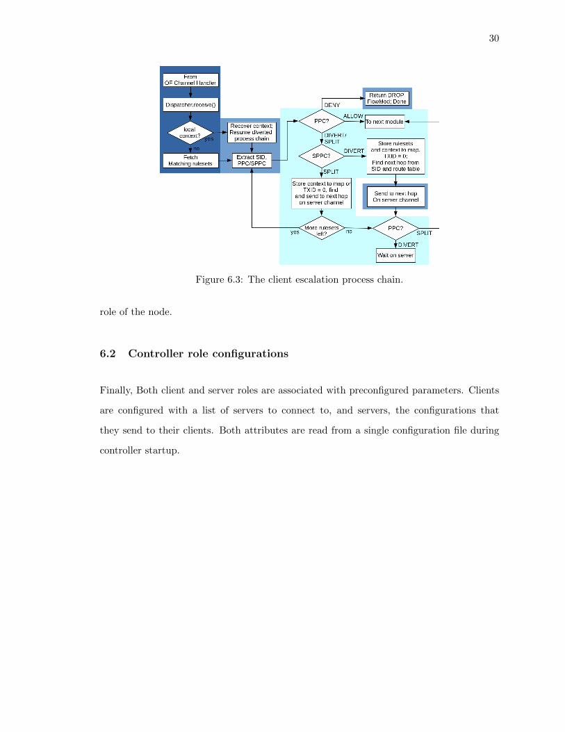
Figures 6.3, 6.4, and 6.5 show the flow of the client escalation, server/peer, and client
return process chains, respectively. The sections corresponding to each of the three layers
of the controller are color-coded with the corresponding colors used for each layer in Figure
6.1. These chains coexist within every node and the activity of each is dependent on the
30
Figure 6.3: The client escalation process chain.
role of the node.
6.2 Controller role configurations
Finally, Both client and server roles are associated with preconfigured parameters. Clients
are configured with a list of servers to connect to, and servers, the configurations that
they send to their clients. Both attributes are read from a single configuration file during
controller startup.
31
Figure 6.4: The server and peer process chains.
Figure 6.5: The client return path process chain.
32
Chapter 7
Evaluation
This section presents some of the performance evaluations that we have done to test the
functionality of this control plane. We run our tests on the ORBIT[33] network testbed.
ORBIT provides time-shared sandboxes that users may build customized OS images for, and
run experiments on. Since the available hardware is not uniform across all sandboxes, we
choose a collection of nodes with the same specifications; The nodes used for the evaluations
have 8GB of RAM and Core i7 CPUs. Each node has two network interfaces, connected to
dedicated VLANs that can be used to separate control and data plane traffic. Each interface
connects to an aggregation switch with gigabit Ethernet links. Tests using Iperf[16] show
throughputs between 808 to 940Mbps, confirming this bandwidth. Figure 7.1 shows the
layout of the sandbox infrastructure.
We consider several factors when evaluating the performance of this control plane:
1. Number of switches. Control packets and channels are tracked in terms of switches
and client nodes. As this value increases, a controller will have larger amounts of
transaction and context mappings to maintain if it needs higher tiers to handle the
events.
2. Number of hosts. Unique host traffic that generates misses at the switch flow table
trigger message events. More hosts intuitively generate more events, as do hosts
communicating across multiple datapaths.
3. Number of control plane hops. Even with high-throughput, low-latency links, a longer
route to a particular service will incur processing delays in the form of network over-
head (propagation, queueing, kernel buffer etc).
33
Figure 7.1: The network layout of an ORBIT sandbox. A user may manipulate the nodes(c1through cn) from the console in order to run experiments. The console is connected to thenodes via the control VLAN aggregate switch (AS1). The Data VLAN interconnects thenodes through an aggregate switch (AS2). Each node is delegated a role during exper-imentation. Here, c1 is chosen as an OpenFlow client, c2 a tier1 node, and cn a tier2node. Control plane traffic (blue arrows) is delegated to one VLAN, and the data planeand OpenFlow channel traffic (red and purple), the other.
4. Number of services. Larger numbers of services(modules) handling a given event
naturally incurs more processing overhead.
5. Listener policy. Event traffic volume above tier 1 in the control plane is directly
related to listener subscriptions; a listen-to-any policy will dispatch every event from
the data plane, whereas more stringent policies will dispatch events less frequently.
Listeners may also request to divert process chains, in which case the dispatcher must
wait for the listener reply before continuing to process an event.
7.1 Control plane overhead
The most prominent feature of this control plane is its hierarchical control network. We
measure the effect of control plane complexity on control packet processing times, focusing
on the impact of route hop count and service subscriptions with DIVERT versus SPLIT
directives.
Using a custom OpenFlow client, a stream of PacketIns were injected into the control plane.
The time between PacketIn transmission and the reception of the corresponding PacketOut
were measured at tier 1 using Tcpdump, and at the client using its logging functions. Two
control plane topologies with three controller configurations were tested. For the first, a
34
variable-length chain of controllers associated with each other as tiers was configured so
that only the highest tier hosted the PacketOut service, and the rest escalated PacketIns to
the service. In the second, a two-tiered topology with a variable numbers of servers in tier 2
was configured with servers that requested Divert directives in one test, and Split directives
in another. For the second topology, each server was assigned a different priority to fix
the dispatch order across multiple trials, with the last server in line hosting the PacketOut
service and the rest, echo services that echo back a clone of a received PacketIn.
For each of the three cases, ten trials of 10,000 PacketIns each were conducted for increasing
tier height for the first topology, and increasing fanout for the second. Figure 7.2 show the
CDFs for the observed processing times of the three cases. The tests subject the control
plane to the worst-case scenario where the higher tiers request escalation of every event.
Discounting link delays, each additional tier adds an average of 0.32 ms of overhead. Sim-
ilarly, each blocking and nonblocking server adds approximately 0.46 and 0.11 ms, respec-
tively. The first two cases are similar, as the client must wait for the server to reply before
taking action, with the differences in value due to each hop in the blocking server case
handling the event with its modules.
7.2 Scalability
Cbench[3] is used to emulate variable numbers of switches and hosts to determine the effects
of local traffic load on a controller’s event processing times. The performance monitor[34]
module is used to access the event handling statistics of the node’s packet processing chain
via its RESTful interface. Figure 7.3 presents average event processing times and rate for a
single controller for varying numbers of switches and hosts. Floodlight’s OpenFlow channel
handler, by default, creates at most four datapath contexts (threads) for the parallelization
of event handling. The minima for the per-packet processing times and the maxima for the
packet processing rates stem from the manifestation of this threading behavior, with each
of the four switches receiving a dedicated thread.
Drawing from baseline performance measurements, four switches are delegated to each tier
35
1 controller for our tiered configuration measurements. A topology of two tiers with one,
two, and four clients in tier1 and one server was tested for loads on the two tiers. The server
configures its clients to escalate message events only associated with new host addresses e.g.
for access control. Figure 7.4 shows the amount of packets processed per unit time by each
tier. We note that the aggregate volume of messages that can be handled at tier 1 increase
proportionally to the number of member nodes, and the amount of messages handled at the
single (global) server is proportional to the number of unique hosts that appear on the data
plane. Additionally, as shown in Figure 7.5, tier 2 packet processing times are minimally
affected by the increase in control message volume since the bulk of the data plane traffic
is handled by tier 1.
7.3 Sample applications.
Finally, we have developed two sample applications for this control plane. Network-scale
authentication is a simple module that scales by placing the authentication service in a
higher tier, shielding it from direct data plane traffic, as demonstrated in Section 7.2. The
location resolution service supplements traffic forwarding services operating in internetworks
where each network has its own controller and is identified as a domain. An upper-tier
controller that has knowledge of domain-level host locations assists lower-tier controllers by
informing them of the destination domain where the non-local host is located. The local
controllers, in turn, advertize and maintain domain location mappings as the client portion
of the service.
In both cases, lower-tier controllers not directly connected to their servers may rely on
peers to route event escalations to the proper destination. In addition, both network stacks
may be combined above the first tier, with authentication operating with a higher priority,
and only on event triggers for new hosts, and the latter, on any new (allowed) traffic flows
needing a host lookup. Figure 7.7 shows an example topology, verified with Mininet[23],
that merges the two service stacks into the same control plane.
36
Figure 7.2: Processing time distributions for multiple tier (left), multiple DIVERT sub-scription (center), and multiple SPLIT subscription (right) routes, each compared againsta baseline (1 node/1 tier) controller.
37
Figure 7.3: Average processing time per event packet (top) and processing rate of incomingpackets (bottom) for a single controller. Datapaths and hosts are emulated using the Cbenchcontroller benchmarker. The dip in the left figure and spike in the right, at four datapaths,reflects the behavior of the Floodlight OpenFlow channel handler.
38
Figure 7.4: The rate of event reception attiers 1 ond 2. The low vaules at tier 2 reflectits subscription to a small subset of events,rather than system load.
Figure 7.5: Packet processing times com-parison between a tier 1 and tier 2 node.The brunt of event handling occurs at tier1.
Figure 7.6: Packet processing times for a client/server pair in the two tiered control network.Processing times for the client are affected by control traffic increase in a nearly identicalmanner to the standalone controller. The server, as a subscriber to just a subset of themessages, are minimally affected.
39
Figure 7.7: A two-tier, three service control plane of four controllers that merges twoseparate service stacks at the first tier. The dotted vertical line denotes the boundarybetween the two domains created by the domain advertisements of the two tier 1 controllers.
40
Chapter 8
Conclusion
This paper presented a survey of the evolution of the OpenFlow-based SDN control plane,
and the various techniques involved in making them scalable and resilient. Despite lacking
native support for these mechanisms, modern controller platforms provide various pro-
grammatic interfaces atop a stable core scheduler/dispatcher that enables them to be both
flexible and robust. As such, we used the Floodlight controller platform to implement a
prototype control plane that supports the coexistence of multiple services. We confirmed
that the hierarchical organization of different services allows this control plane to both scale
and combine service stacks flexibly. On the other hand, being a network itself, control plane
performance becomes sensitive to link qualities. While acceptable for typical wired network
applications that experience moderate traffic loads, it is currently ill-suited for services with
fast convergence requirements e.g. coordination of wireless networks.
Our prototype leaves many components open to improvement, and topics for future works:
• Self-organization: The control plane may incorporate methodologies for self-organization
of the hierarchy using discovery protocols or zero-configuration techniques. Manually
configured aspects of each controller, such as SID and UUID assignment, may also be
assigned through node discovery.
• Security: The current control plane is assumed to be deployed in a secure, dedicated
network. A practical implementation must consider security mechanisms, including
the prevention of control plane compromises due to malicious or misconfigured con-
trollers.
• Applications: Outside of the NOS components of the control plane, the design of
41
services that can effectively take advantage of this architecture is an open subject.
Such applications may make use of the inter-controller interface in order to allow
independent networks to peer at the control plane, or fine-tune event handling to
implement virtualization schemes.
• Improved components: The various implemented components, such as route adver-
tisement mechanisms and the inter-controller control protocol, may be exchanged for
more efficient schemes that are not just aimed at fast prototyping.
• Control protocol extensions: With further investigation, it may be possible to develop
a better-refined definition of heterogeneous control plane properties, notably in the
domain of inter-controller communication schemes. Such schemes may be proposed
as additions to OpenFlow protocol specifications to enable it to support a richer set
of control plane functions than as of current.
In short, our design and implementation of the hierarchical control plane is not intended to
be the solution, but only an early-stage attempt at exploring this architecture.
42
References
[1] Beacon - Confluence. https://openflow.stanford.edu/display/Beacon/Home.
[2] Big Network Controller Is The Network Application Platform For Open SDN — — BigSwitch Networks, Inc. http://www.bigswitch.com/products/SDN-Controller.
[3] Cbench. http://www.openflowhub.org/display/floodlightcontroller/Cbench.
[4] Cisco Network Assistant. http://www.cisco.com/en/US/products/ps5931/index.
html.
[5] A. Curtis, J. Mogul, J. Tourrilhes, P. Yalagandula, P. Sharma, and S. Banerjee. De-voFlow: scaling flow management for high-performance networks. in Proceedings of theACM SIGCOMM 2011 conference, pp. 254-265, Aug. 2011.
[6] N. Feamster, J. Rexford, S. Shenker, D. Levin , R. Clark, and J. Bailey. SDX: A SoftwareDefined Internet Exchange. ONS’13
[7] A. Ferguson, A. Guha, C. Liang, R. Fonseca, and S. Krishnamurthi. Hierarchical policiesfor software defined networks. in HotSDN’12 Proceedings of the first workshop on Hottopics in software defined networks, pp. 37-42, Aug. 2012.
[8] A. Ferguson, A. Guha, J. Place, R. Fonseca, and S. Krishnamurthi. Participatory net-working. in Proceedings of the 2nd USENIX conference on Hot Topics in Managementof Internet, Cloud, and Enterprise Networks and Services, p. 2, Apr. 2012.
[9] Floodlight Architecture. http://docs.projectfloodlight.org/display/
floodlightcontroller/Architecture.
[10] Floodlight Is An Open SDN Controller. http://floodlight.openflowhub.org/.
[11] N. Foster, R. Harrison, M. Freedman, C. Monsanto, J. Rexford, A. Story, andD. Walker. Frenetic: A Network Programming Language. In ACM SIGPLAN In-ternational Conference on Functional Programming (ICFP), Tokyo, Japan, Sep. 2011.
[12] GENI - Exploring Networks of the Future. http://www.geni.net/.
[13] N. Gude, T. Koponen, J. Pettit, B. Pfaff, M. Casado, N. McKeown, and S. Shenker.NOX: towards an operating system for networks. in ACM SIGCOMM Computer Com-munication Review, Volume 38 Issue 3, pp. 105-110, Jul. 2008.
[14] Indigo - Open Source OpenFlow Switches. http://www.openflowhub.org/display/Indigo/Indigo+-+Open+Source+OpenFlow+Switches.
[15] Infrastructure Sharing and Colocation — ICT Regulation Toolkit. http://www.
ictregulationtoolkit.org/en/Section.3563.html.
43
[16] Iperf - TCP and UDP bandwidth performance measurement tool. http://code.
google.com/p/iperf/
[17] Juniper Networks - Network Management. http://www.juniper.net/us/en/
products-services/network-management/.
[18] T. Koponen, M. Casado, N. Gude, J. Stribling, L. Poutievski, M. Zhu, R. Ramanathan,Y. Iwata, H. Inoue, T. Hama, and S. Shenker. Onix: A Distributed Control Platformfor Large-scale Production Networks. in OSDI’10 Proceedings of the 9th USENIX con-ference on Operating systems design and implementation, pp. 1-6, Oct. 2010.
[19] C. Kozierok. TCP/IP Guide - A Comprehensive, Illustrated Internet Protocols Refer-ence, Nostarch Press, Inc., San Francisco, Oct. 2005, Chap. 23.
[20] U. Krishnaswamy, P. Berde, J. Hart, M. Kobayashi, P. Radoslavov, T. Lindberg,R. Sverdlov, S. Zhang, W. Snow, and G. Parulkar. Open Network Operating Sys-tem: An Experimental Open-Source Distributed SDN OS. http://www.slideshare.net/umeshkrishnaswamy/open-network-operating-system
[21] P. Lin. J. Hart, U. Krishnaswamy, T. Murakami, M. Kobayashi, A. Al-Shabibi. Seam-less Interworking of SDN and IP. to appear in HotSDN’13 Proceedings of the secondworkshop on Hot Topics in Software Defined Networking, Aug. 2013.
[22] Maestro-platform, A scalable control platform writen in Java which supports OpenFlowswitches. http://code.google.com/p/maestro-platform/.
[23] Mininet: Rapid Prototyping for Software Defined Networks. http://yuba.stanford.edu/foswiki/bin/view/OpenFlow/Mininet.
[24] C. Monsanto, N. Foster, R. Harrison, and D. Walker. A compiler and run-time systemfor network programming languages. in Proceedings of the 39th annual ACM SIGPLAN-SIGACT symposium on Principles of programming languages, pp. 217-230, Jan. 2012.
[25] NEC IP8800 OpenFlow Networking. http://support.necam.com/Pflow/IP8800/
[26] OFTest – Validating OpenFlow Swtiches. http://oftest.openflowhub.org/.
[27] OpenFlow Switch Specification. https://www.opennetworking.org/about/
onf-documents.
[28] Open Networking Foundation. https://www.opennetworking.org/.
[29] Open Networking Foundation. Software-Defined Networking: The New Norm for Net-works. https://www.opennetworking.org/about/onf-documents.
[30] OpenvSwitch, An Open Virtual Switch. http://openvswitch.org/.
[31] OpenFlow Downloads - OpenFlow Switching Reference System. http://www.
openflow.org/wp/downloads/
[32] ON.LAB - TestON http://onlab.us/testing.html
[33] ORBIT. http://www.orbit-lab.org/.
[34] PktInProcessingTime. http://floodlight-javadoc.projectfloodlight.org/.
44
[35] L. Prete. (2012, Aug) problem activating learning switch. Floodlight-developers mailinglist, https://groups.google.com/a/openflowhub.org/d/topic/floodlight-dev/
YnU2HQVPqeE/discussion.
[36] C. Rotsos, N. Sarrar, S. Uhlig, R. Sherwood, and A. Moore. OFLOPS: an open frame-work for openflow switch evaluation. in PAM’12 Proceedings of the 13th internationalconference on Passive and Active Measurement, pp. 85-95, Mar. 2012.
[37] rpcbind(8) - FreeBSD System Manager’s Manual. http://www.freebsd.org/cgi/
man.cgi?query=rpcbind\&sektion=8
[38] Ryu, Python-based OpenFlow controller but we aim for bigger pictures. http://osrg.github.com/ryu/.
[39] R. Sherwood, G. Gibb, K. Yap, G. Appenzeller, N. McKeown, and G. Parulkar. Flowvi-sor: A network virtualization layer. Tech. Rep. OPENFLOW-TR-2009-01, OpenFlowConsortium, Oct. 2009.
[40] H. Shimonishi, S. Ishii, Y. Chiba, T. Koide, M. Takahashi, Y. Takamiya, and L. Sun.Helios: Fully Distributed OpenFlow Controller Platform. 9th GENI Engineering Con-ference (GEC9) Demo, Nov. 2010.
[41] Simple Network Management Protocol - Wikipedia. http://en.wikipedia.org/
wiki/Simple\ Network\ Management\ Protocol.
[42] J. Stringer, Q. Fu, C. Lorier, R. Nelson, and C. Rothenberg. Cardigan: Deploying aDistributed Routing Fabric. to appear in HotSDN’13 Proceedings of the second workshopon Hot Topics in Software Defined Networking, Aug. 2013.
[43] A. Tootoonchian and Y. Ganjali. HyperFlow: A Distributed Control Plane for Open-Flow. in INM/WREN’10 Proceedings of the 2010 internet network management con-ference on Research on enterprise networking, p. 3, Apr. 2010.
[44] Trema, Full-Stack OpenFlow Framework in Ruby and C. http://trema.github.com/trema/.
[45] The UPnP Forum. UPnP Device Architecture 1.1, Oct. 2008. http://upnp.org/sdcps-and-certification/standards/device-architecture-documents/
[46] A. Voellmy, and P. Hudak. Nettle: A Language for Configuring Routing Networks.in DSL’09 Proceedings of the IFIP TC 2 Working Conference on Domain-Specific Lan-guages, pp. 211-235, 2009.
[47] V. Yazici, M. Sunay, and A. Ercan. Controlling a Software Defined Network via Dis-tributed Controllers. in NEM’12 Summit Proceedings, pp. 16-21, Oct. 2012.
[48] S. Yeganeh and Y. Ganjali. Kandoo: a framework for efficient and scalable offloadingof control applications. in HotSDN’12 Proceedings of the first workshop on Hot topicsin software defined networks, pp. 19-24, Aug. 2012.
[49] M. Yu , J. Rexford, M. Freedman, and J. Wang. Scalable flow-based networking withDIFANE. in Proceedings of the ACM SIGCOMM 2010 conference on SIGCOMM, pp.351-362, Sep.-Aug. 2010.