Embed Size (px)
Citation preview

The Design and Building of a Human Powered Submarine
Don Burton
Independent Entry
Frederick Maryland 21703
Abstract The human powered submarine race is a contest
where ideas and education can be tested This paper
describes a submarine that will use a nine blade variable
pitch propeller assembly to provide thrust for the submarine
using human power The design and fabrication ideas also
look at the stream line of the ships hull where the sides are
concaved into the hull to see if the flow will guide the
separated boundary layer will flow back into the propeller
faster
Introduction
The Human Powered Submarine Race (ISR)trade and the
Foundation of Underwater Research and Education
(FURE)trade have put together one of the more unusual
races world wide The contestant manual available at
the race web site httpwwwisrsubraceorg is where to
start your project
All contestants are given a choice as to the design
category they wish to enter It can be a one or two
person sub propeller or non-propeller but all must be
free flooding and with the diver or divers using scuba
gear
Safety has the highest priority of the race No one is
allowed to be in the water without a certification for
scuba diving also the craft must pass a land inspection
and a water safety inspection for emergency egress and
safety buoy
Picture 1 Rough form of the hull
Human Power Output
The data suggests that the horsepower that a human
can produce be in the area of 33 hp[1] for a male that
is in very good shape using a bicycle cadence of
around 45-55 rpm at the crank Under water this
amount could be reduced somewhat so the propullsor
could have a horsepower of around 15 to about 25
The amount of torque for this amount of hp could be
calculated using the formula
T= 5252 x hp RPM (1)
Therefore if the amount of horse power available is
25 times 5252 equals 1313 divided by 50 rpm we
have 2626 foot pounds of torque available This is the
amount available at the propeller shaft Compare this
to your drag racing funny car and say you have a 350
hp engine that red lines at 5000 rpm You would have
a torque amount of 36764 foot pounds of torque This
is what pushes you back in the seat
Knowing that the submarine will operate under water
the force applied to the propeller has a certain amount
of slippage when accelerating the water Like drag
racing the tires will spin at the instant start and
depending on how efficiently the RPMrsquos and gearing
are used you can test for the right combination [3]
By looking at several methods of gearing I would like
to achieve moving a large amount of water with a
variable pitch propeller There are two options you
can use for using any propeller system you can have
a small diameter prop moving very fast or a large
bladed prop moving slowly As you look at the
amount of water going by the propellers they are the
same amount (conservation of mass) [2] the stream
tube produced has an area that I wanted to look at to
see if there were any advantages as the stream effects
on the hull See Picture 1
Hull Shape
The hull shape chosen was one that would place the
flow stream along the sides of the hull to prevent
boundary layer separation [6] Most of the NACA
airfoils show the side profiles which provide the best
form for lift The profiles were used as a guide line
for the placement of the concave sides keeping in
mind that the water would be spatial The submarine
would be moving through the water not so much as to
generate lift but to have a shape that is laminar and
will channel the flow into the propeller blades for
capturing the incoming water See Figure1 and
Picture 1
1
2
34
56
78
910 11
12 1314 15 16
17 18 19 2021 22 23 25 26
2728
2930 31 32 33 34 35 36 37 38 39 40
41
4243
44
45
46
47
48
7461
3814
5354
6510
82788999
964410229
1076211252 11703 12120 12507 12866 13199 13508 13796 14062 14309 14538 14749 14942 15120 15282 15428 15560 15677 15780 15870 15945 16007 16056 16092 16115 16092 15945 15677 15282
1474914062
1319912120
10762
8999
6510
Figure 1 Hull shape
Picture 2
By concaving the hull and the variable pitch propeller
system in with the hull an advantage can be taken
with the stream tube as it passes through the prop [4]
When the water is accelerated it contracts on the out
put end This contraction would appear to squeeze the
back end of the sub forcing it forward
The old Sintra form is used from the last ISR sub race
was reconstructed to see if by concaving the sides
inboard This was done to aid the free stream flowing
into the propeller disc area Most of the port and
starboard sides along the hull were brought in The top
and bottom rear area was the only area sunk in for gear
placement purposes The top rear concave section also
is used as a hatch for drive assembly maintenance seen
in Picture 4
Picture 3
Picture 4
Picture 5
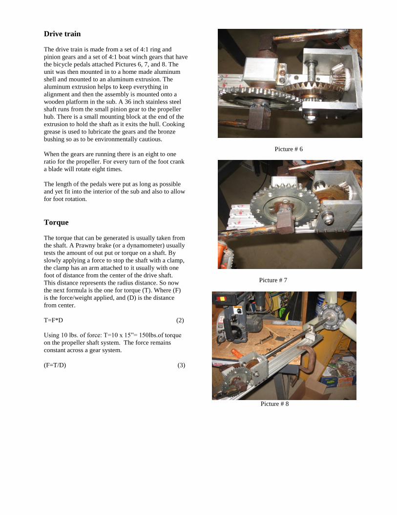
Drive train
The drive train is made from a set of 41 ring and
pinion gears and a set of 41 boat winch gears that have
the bicycle pedals attached Pictures 6 7 and 8 The
unit was then mounted in to a home made aluminum
shell and mounted to an aluminum extrusion The
aluminum extrusion helps to keep everything in
alignment and then the assembly is mounted onto a
wooden platform in the sub A 36 inch stainless steel
shaft runs from the small pinion gear to the propeller
hub There is a small mounting block at the end of the
extrusion to hold the shaft as it exits the hull Cooking
grease is used to lubricate the gears and the bronze
bushing so as to be environmentally cautious
When the gears are running there is an eight to one
ratio for the propeller For every turn of the foot crank
a blade will rotate eight times
The length of the pedals were put as long as possible
and yet fit into the interior of the sub and also to allow
for foot rotation
Torque
The torque that can be generated is usually taken from
the shaft A Prawny brake (or a dynamometer) usually
tests the amount of out put or torque on a shaft By
slowly applying a force to stop the shaft with a clamp
the clamp has an arm attached to it usually with one
foot of distance from the center of the drive shaft
This distance represents the radius distance So now
the next formula is the one for torque (T) Where (F)
is the forceweight applied and (D) is the distance
from center
T=FD (2)
Using 10 lbs of force T=10 x 15rdquo= 150lbsof torque
on the propeller shaft system The force remains
constant across a gear system
(F=TD) (3)
Picture 6
Picture 7
Picture 8
Propeller Assembly
The mounting of the blade fins has three selections for
the Helix angle A helix is a curve that is made by a
point traveling around a cylinder at a constant rate
with the same direction of the axis [5] I will be able
to place a combination of blades from two blades up
to nine blades I can also change the blade helix angle
from 30 degrees to 45 and 60 degrees
The whole assembly was purchased on line and I
thought it would be a useful item to study
The assembly comes with nine blades and has a tip
diameter of 28 inches The hub is split in half to allow
for the blades to change pitch angle The hub is made
from an investment casting and is light weight
The hub is cast so that there are notches for a small
dowel to hold the stub portion of the blade at the pitch
angle you want The first notch I used had the pitch
angle way to steep so I drilled and tapped for a set
screw to adjust for smaller angles of attack
This type of assembly should allow me to study if a
person can really move 9 blades in the water The
amount of surface area to be cranked is a lot and with
about frac14 horse power it should be interesting
Picture rsquos 9a 9b
Picture rsquos 10a 10b 10c
The Sintrareg PVC Core Hull
I believe the newest material that will be introduced at
this years sub race will be that of a material known as
Sintrareg This is an expanded high density plastic
PVC sheet with many properties especially being
water proof I used two sheets one for the top one for
the bottom By using the 4rsquox8rsquox 6mm sheets I was
able to incorporate a lot of the features that I needed
for control surfaces seen in Picture 13
Picture 11
Sintrareg is used in the sign making industry because it
is easily formed and cut and can be shaped by blow
molding which I used or vacuum forming andor
cutting and bonding using PVC adhesive such as that
used in the plumbing industry The material is very
smooth even when it is stretched out into the two hull
forms that I wanted As with any procedures I try to
use it took me six attempts and six sheets before I
achieved the proper shape It seems the material has a
memory to it and as soon as you take the heat off it
wants to go back to a flat shape The sheet also has
some areas that are hot spots and I had to move the
heater around and use baffles to find a sweet spot to get
even heating A Sintrareg heat chart explains the various
temperatures at which the material will start to deform
degrade The material is very easy to work with and is
lightweight even a 4 x 8 foot sheet Once the material
was at the proper shape little else had to be done to
shape the hull The material is not strong on the surface
just like on a PVC pipe you have in a plumbing
system By roughing up the surface I added 5 layers of
epoxy sanding each layer for bonding The Garrie Hill
bike fairing was the source for this type of hull [8]
Picture 12
Figure 2
Picture 13
The Hull Template The hull template was cut from a 4rsquox8rsquo x34 inch piece of
plywood These pictures show the one that worked Do
not use particle chip board or the cheap piece of
plywood I found out that these types of boards tend to
allow for small leaks through the layers and or the chips
however small THE SEAL IS VERY IMPORTANT
Please make a note of this
I projected the form from the center line every 2 inches to
get one half of the shape seen in Figure 3 I made the first
out line on a large piece of cardboard and to use as a
template This proved to be an advantage because of the
two inferior wood products I used first (a) Chip board
and (b) the cheap plywood with the knot holes in it both
proved that the air would leak even after I tried to seal
the boards with paint
Next a door gasket was used between the sandwiched
plywood to create the barrier needed to form the hull
The top 4x8 plywood was then screwed around the
perimeter to hold the seal and the two sheets together
The air line is shown going into the top of the oven
1
2
34
56
78
910 11
12 1314 15 16
17 18 19 2021 22 23 25 26
2728
2930 31 32 33 34 35 36 37 38 39 40
41
4243
44
45
46
47
48
7461
3814
5354
6510
82788999
964410229
1076211252 11703 12120 12507 12866 13199 13508 13796 14062 14309 14538 14749 14942 15120 15282 15428 15560 15677 15780 15870 15945 16007 16056 16092 16115 16092 15945 15677 15282
1474914062
1319912120
10762
8999
6510
Figure 3
Picture 14
Picture 15
Picture 16
Picture 17
The Oven A large used packing crate was procured from the
dumpster It had the right dimensions for the hull project
of the sub and was FREE Shipping and handling not
included The original top was the cheap knotty plywood
mentioned earlier and had to many leaks The next cut
out was done with the chip board also to many leaks
I next welded a frame for around the top for the
Sandwich mold to sit on seen in picture 18 Insulation
was added around the bow and the missing front door
This door was easily removed and I found out that by
quickly removing the door helped set the material and
cool faster (Trial and error method)
I first tried a kerosene heater but could not control the
temperature as well as the propane one Two small
openings were cut in the control side of the oven one for
a visual area to see the hull forming and to control the air
bursts into the mold and the other was to provide make
up air for the heat and to adjust the control knob for
temperature (another trial and error spot) A post was
built to gauge the depth of the form taken from the
bottom side of the PVC This would give me the outer
hull dimension The post also held the oven temperature
gauge along with a rubber orange piece to show where
each half would have to reach in order to be symmetrical
When the material is at about 350 Fdeg it has the feel of
chewing gum to it and will form to what ever touches it
So in order not to punch a hole in the PVC a piece of
rubber would bend as it touched This also allowed me to
control the air pressure by watching the tip so that each
half would be the same 15 inches The gas was turned off
and the front door drop to quickly cool the form when the
desired shape was achieved
A drop light was set inside to watch the form take shape
and to se the temperature gauge In order to distribute the
heat evenly a cast iron plate was placed on top of the
heater for the first layer and an aluminum plate much
longer was placed on top of the iron to distribute heat
from front to back
It should be noted here that Murphyrsquos Law was alive and
well during the hull forming exercise The six attempts to
form the hull ranged from hot spots that blew out on the
sides air leaks in wood and seal running out of propane
at a critical point in the process to a lightning storm that
did not give me a warm fuzzy feeling sitting next to a
propane tank
All in all I had learned a great deal about this sort of
forming plastics and will use the oven for forming some
acrylics and Lexan bubbles
Picture 18
Picture 19
Picture 20
Picture 21
Picture 22
Picture 23
Picture 24
Picture 25
Picture 26
Life Support and Scuba Equipment
The life support equipment will consist of certified air
tanks that have current visual and hydro safety
inspections in order to be refilled at the races The sub
will carry 1 size 80 tank and will be mounted under the
center line of the hull beneath thedriver again keeping in
mind that it will help in stabilizing the torque placed on
the hull by the propeller The Diver on board will also be
carrying two spare air bottles one will be carried on the
diver and one will be on the steering bars in case of an
emergency egress or if the on board regulator fails
The diver will have the option of wearing a full wet suit
(recommended) or if itrsquos warm enough at the race to wear
a short suit to make a run with out being in the water to
long
The air that is exhaled will be vented out through the top
fin of the sub in order to prevent any ventilation in to the
propeller The blades will slip enough without air being
sucked into the path
The emergency buoy will be held by a bicycle hand break
much like the one I had used in previous Subs The buoy
has 30 feet of high visible line that is required by the race
manual
A high visible strobe is placed on the top fin in order to
be seen 360 all around
Picture 27
Picture 28
Picture 29
Picture 30
The Cost Estimate The following page represents a cost estimate if I were
to send out to a vendor to have the work done An
engineering group would provide the design and
drawing documents and provide parts list for
purchasing and bids I used $4500 an hour as an
average estimate you could very well add more
depending on where or who did the work Having done
the project myself the real cost is closer to the dollar
estimate of $265000 With scavenging and on line
auctions the total for the project $32000
Cost EstimateDollars Hours
Design Hours 120
Drafting Hours 80
Purchasing Hours 20
Dive Site Testing hours 50
Research and Reference Hours 40
Rental EquipmentTransportation $35000
Dive equipment $40000
LodgingFood $25000
Hardware Material $50000
Welding Hours 25
Machining Hours 40
Assembly Hours 40
Fiber glass Hours 120
Sanding Polishing Hours 20
Painting Costs $15000
Race Entry Fee $100000
Sub Totals $265000 555
Rate $4500 per hour x $4500
$2497500
Total Estimated Cost $2762500
When searching for human power information the
WISIL HPVerrsquos home page
httpwwwwisilrecumbentcom was a very valuable
source for recumbent information Most noticeable was
the fact a human powered recumbent bike was clocked
at more than 80 MPH[7] I read it several times to
make sure I was including the right numbers
By looking at the design I have presented in this paper
the real test comes from the actual contest at David
Taylor Model Basin The sub race will allow me to test
whether my type of hull with the concave sides can be
faster than the subs that have round cylindrical forms
References
[1] Ballantine Richard and Grant Richard
Richardsrsquo Ultimate Bicycle Book Dorling
KindersleyInc 1992 pp 136-137
[2] Benson Tom (January 2002) Mass Flow Rate
[Home Page of Glen Research Center] Online
Available httpwwwgrcnasagovWWWK-
12airplanemflowhtml (Sept 2002)
[3] Bump John (1999) Bicycle Efficiency and
Powermdashor Why Bikes Have Gears pp 1-7
Available
httpwwwfriicom~katanabiketexthtml (Feb
2003)
[4] Burcher R Rydill L Concepts in Submarine
Design Cambridge University Press 1994 pp
119-123
[5] Oberg Erik Machineryrsquos Handbook Industrial
Press Inc January 1997 p 2037
[6] Osse James Low Drag Technology applied to
Human Powered Vehicles Oceans 89 Volume 6
Human powered Submersibles June1989 pp 7-
11
[7] Beauchamp Warren (2002) WISL Human
Powered Vehicle Web Site
httpwwwwisilrecumbentcom (October
2002)
[8] Hill Garrie (2002) WISIL Human Powered
Vehicle Web Site
httpwwwwisil
recumbentcomwisilhillgarriehillhtm
(October 2002)

mind that the water would be spatial The submarine
would be moving through the water not so much as to
generate lift but to have a shape that is laminar and
will channel the flow into the propeller blades for
capturing the incoming water See Figure1 and
Picture 1
1
2
34
56
78
910 11
12 1314 15 16
17 18 19 2021 22 23 25 26
2728
2930 31 32 33 34 35 36 37 38 39 40
41
4243
44
45
46
47
48
7461
3814
5354
6510
82788999
964410229
1076211252 11703 12120 12507 12866 13199 13508 13796 14062 14309 14538 14749 14942 15120 15282 15428 15560 15677 15780 15870 15945 16007 16056 16092 16115 16092 15945 15677 15282
1474914062
1319912120
10762
8999
6510
Figure 1 Hull shape
Picture 2
By concaving the hull and the variable pitch propeller
system in with the hull an advantage can be taken
with the stream tube as it passes through the prop [4]
When the water is accelerated it contracts on the out
put end This contraction would appear to squeeze the
back end of the sub forcing it forward
The old Sintra form is used from the last ISR sub race
was reconstructed to see if by concaving the sides
inboard This was done to aid the free stream flowing
into the propeller disc area Most of the port and
starboard sides along the hull were brought in The top
and bottom rear area was the only area sunk in for gear
placement purposes The top rear concave section also
is used as a hatch for drive assembly maintenance seen
in Picture 4
Picture 3
Picture 4
Picture 5
Drive train
The drive train is made from a set of 41 ring and
pinion gears and a set of 41 boat winch gears that have
the bicycle pedals attached Pictures 6 7 and 8 The
unit was then mounted in to a home made aluminum
shell and mounted to an aluminum extrusion The
aluminum extrusion helps to keep everything in
alignment and then the assembly is mounted onto a
wooden platform in the sub A 36 inch stainless steel
shaft runs from the small pinion gear to the propeller
hub There is a small mounting block at the end of the
extrusion to hold the shaft as it exits the hull Cooking
grease is used to lubricate the gears and the bronze
bushing so as to be environmentally cautious
When the gears are running there is an eight to one
ratio for the propeller For every turn of the foot crank
a blade will rotate eight times
The length of the pedals were put as long as possible
and yet fit into the interior of the sub and also to allow
for foot rotation
Torque
The torque that can be generated is usually taken from
the shaft A Prawny brake (or a dynamometer) usually
tests the amount of out put or torque on a shaft By
slowly applying a force to stop the shaft with a clamp
the clamp has an arm attached to it usually with one
foot of distance from the center of the drive shaft
This distance represents the radius distance So now
the next formula is the one for torque (T) Where (F)
is the forceweight applied and (D) is the distance
from center
T=FD (2)
Using 10 lbs of force T=10 x 15rdquo= 150lbsof torque
on the propeller shaft system The force remains
constant across a gear system
(F=TD) (3)
Picture 6
Picture 7
Picture 8
Propeller Assembly
The mounting of the blade fins has three selections for
the Helix angle A helix is a curve that is made by a
point traveling around a cylinder at a constant rate
with the same direction of the axis [5] I will be able
to place a combination of blades from two blades up
to nine blades I can also change the blade helix angle
from 30 degrees to 45 and 60 degrees
The whole assembly was purchased on line and I
thought it would be a useful item to study
The assembly comes with nine blades and has a tip
diameter of 28 inches The hub is split in half to allow
for the blades to change pitch angle The hub is made
from an investment casting and is light weight
The hub is cast so that there are notches for a small
dowel to hold the stub portion of the blade at the pitch
angle you want The first notch I used had the pitch
angle way to steep so I drilled and tapped for a set
screw to adjust for smaller angles of attack
This type of assembly should allow me to study if a
person can really move 9 blades in the water The
amount of surface area to be cranked is a lot and with
about frac14 horse power it should be interesting
Picture rsquos 9a 9b
Picture rsquos 10a 10b 10c
The Sintrareg PVC Core Hull
I believe the newest material that will be introduced at
this years sub race will be that of a material known as
Sintrareg This is an expanded high density plastic
PVC sheet with many properties especially being
water proof I used two sheets one for the top one for
the bottom By using the 4rsquox8rsquox 6mm sheets I was
able to incorporate a lot of the features that I needed
for control surfaces seen in Picture 13
Picture 11
Sintrareg is used in the sign making industry because it
is easily formed and cut and can be shaped by blow
molding which I used or vacuum forming andor
cutting and bonding using PVC adhesive such as that
used in the plumbing industry The material is very
smooth even when it is stretched out into the two hull
forms that I wanted As with any procedures I try to
use it took me six attempts and six sheets before I
achieved the proper shape It seems the material has a
memory to it and as soon as you take the heat off it
wants to go back to a flat shape The sheet also has
some areas that are hot spots and I had to move the
heater around and use baffles to find a sweet spot to get
even heating A Sintrareg heat chart explains the various
temperatures at which the material will start to deform
degrade The material is very easy to work with and is
lightweight even a 4 x 8 foot sheet Once the material
was at the proper shape little else had to be done to
shape the hull The material is not strong on the surface
just like on a PVC pipe you have in a plumbing
system By roughing up the surface I added 5 layers of
epoxy sanding each layer for bonding The Garrie Hill
bike fairing was the source for this type of hull [8]
Picture 12
Figure 2
Picture 13
The Hull Template The hull template was cut from a 4rsquox8rsquo x34 inch piece of
plywood These pictures show the one that worked Do
not use particle chip board or the cheap piece of
plywood I found out that these types of boards tend to
allow for small leaks through the layers and or the chips
however small THE SEAL IS VERY IMPORTANT
Please make a note of this
I projected the form from the center line every 2 inches to
get one half of the shape seen in Figure 3 I made the first
out line on a large piece of cardboard and to use as a
template This proved to be an advantage because of the
two inferior wood products I used first (a) Chip board
and (b) the cheap plywood with the knot holes in it both
proved that the air would leak even after I tried to seal
the boards with paint
Next a door gasket was used between the sandwiched
plywood to create the barrier needed to form the hull
The top 4x8 plywood was then screwed around the
perimeter to hold the seal and the two sheets together
The air line is shown going into the top of the oven
1
2
34
56
78
910 11
12 1314 15 16
17 18 19 2021 22 23 25 26
2728
2930 31 32 33 34 35 36 37 38 39 40
41
4243
44
45
46
47
48
7461
3814
5354
6510
82788999
964410229
1076211252 11703 12120 12507 12866 13199 13508 13796 14062 14309 14538 14749 14942 15120 15282 15428 15560 15677 15780 15870 15945 16007 16056 16092 16115 16092 15945 15677 15282
1474914062
1319912120
10762
8999
6510
Figure 3
Picture 14
Picture 15
Picture 16
Picture 17
The Oven A large used packing crate was procured from the
dumpster It had the right dimensions for the hull project
of the sub and was FREE Shipping and handling not
included The original top was the cheap knotty plywood
mentioned earlier and had to many leaks The next cut
out was done with the chip board also to many leaks
I next welded a frame for around the top for the
Sandwich mold to sit on seen in picture 18 Insulation
was added around the bow and the missing front door
This door was easily removed and I found out that by
quickly removing the door helped set the material and
cool faster (Trial and error method)
I first tried a kerosene heater but could not control the
temperature as well as the propane one Two small
openings were cut in the control side of the oven one for
a visual area to see the hull forming and to control the air
bursts into the mold and the other was to provide make
up air for the heat and to adjust the control knob for
temperature (another trial and error spot) A post was
built to gauge the depth of the form taken from the
bottom side of the PVC This would give me the outer
hull dimension The post also held the oven temperature
gauge along with a rubber orange piece to show where
each half would have to reach in order to be symmetrical
When the material is at about 350 Fdeg it has the feel of
chewing gum to it and will form to what ever touches it
So in order not to punch a hole in the PVC a piece of
rubber would bend as it touched This also allowed me to
control the air pressure by watching the tip so that each
half would be the same 15 inches The gas was turned off
and the front door drop to quickly cool the form when the
desired shape was achieved
A drop light was set inside to watch the form take shape
and to se the temperature gauge In order to distribute the
heat evenly a cast iron plate was placed on top of the
heater for the first layer and an aluminum plate much
longer was placed on top of the iron to distribute heat
from front to back
It should be noted here that Murphyrsquos Law was alive and
well during the hull forming exercise The six attempts to
form the hull ranged from hot spots that blew out on the
sides air leaks in wood and seal running out of propane
at a critical point in the process to a lightning storm that
did not give me a warm fuzzy feeling sitting next to a
propane tank
All in all I had learned a great deal about this sort of
forming plastics and will use the oven for forming some
acrylics and Lexan bubbles
Picture 18
Picture 19
Picture 20
Picture 21
Picture 22
Picture 23
Picture 24
Picture 25
Picture 26
Life Support and Scuba Equipment
The life support equipment will consist of certified air
tanks that have current visual and hydro safety
inspections in order to be refilled at the races The sub
will carry 1 size 80 tank and will be mounted under the
center line of the hull beneath thedriver again keeping in
mind that it will help in stabilizing the torque placed on
the hull by the propeller The Diver on board will also be
carrying two spare air bottles one will be carried on the
diver and one will be on the steering bars in case of an
emergency egress or if the on board regulator fails
The diver will have the option of wearing a full wet suit
(recommended) or if itrsquos warm enough at the race to wear
a short suit to make a run with out being in the water to
long
The air that is exhaled will be vented out through the top
fin of the sub in order to prevent any ventilation in to the
propeller The blades will slip enough without air being
sucked into the path
The emergency buoy will be held by a bicycle hand break
much like the one I had used in previous Subs The buoy
has 30 feet of high visible line that is required by the race
manual
A high visible strobe is placed on the top fin in order to
be seen 360 all around
Picture 27
Picture 28
Picture 29
Picture 30
The Cost Estimate The following page represents a cost estimate if I were
to send out to a vendor to have the work done An
engineering group would provide the design and
drawing documents and provide parts list for
purchasing and bids I used $4500 an hour as an
average estimate you could very well add more
depending on where or who did the work Having done
the project myself the real cost is closer to the dollar
estimate of $265000 With scavenging and on line
auctions the total for the project $32000
Cost EstimateDollars Hours
Design Hours 120
Drafting Hours 80
Purchasing Hours 20
Dive Site Testing hours 50
Research and Reference Hours 40
Rental EquipmentTransportation $35000
Dive equipment $40000
LodgingFood $25000
Hardware Material $50000
Welding Hours 25
Machining Hours 40
Assembly Hours 40
Fiber glass Hours 120
Sanding Polishing Hours 20
Painting Costs $15000
Race Entry Fee $100000
Sub Totals $265000 555
Rate $4500 per hour x $4500
$2497500
Total Estimated Cost $2762500
When searching for human power information the
WISIL HPVerrsquos home page
httpwwwwisilrecumbentcom was a very valuable
source for recumbent information Most noticeable was
the fact a human powered recumbent bike was clocked
at more than 80 MPH[7] I read it several times to
make sure I was including the right numbers
By looking at the design I have presented in this paper
the real test comes from the actual contest at David
Taylor Model Basin The sub race will allow me to test
whether my type of hull with the concave sides can be
faster than the subs that have round cylindrical forms
References
[1] Ballantine Richard and Grant Richard
Richardsrsquo Ultimate Bicycle Book Dorling
KindersleyInc 1992 pp 136-137
[2] Benson Tom (January 2002) Mass Flow Rate
[Home Page of Glen Research Center] Online
Available httpwwwgrcnasagovWWWK-
12airplanemflowhtml (Sept 2002)
[3] Bump John (1999) Bicycle Efficiency and
Powermdashor Why Bikes Have Gears pp 1-7
Available
httpwwwfriicom~katanabiketexthtml (Feb
2003)
[4] Burcher R Rydill L Concepts in Submarine
Design Cambridge University Press 1994 pp
119-123
[5] Oberg Erik Machineryrsquos Handbook Industrial
Press Inc January 1997 p 2037
[6] Osse James Low Drag Technology applied to
Human Powered Vehicles Oceans 89 Volume 6
Human powered Submersibles June1989 pp 7-
11
[7] Beauchamp Warren (2002) WISL Human
Powered Vehicle Web Site
httpwwwwisilrecumbentcom (October
2002)
[8] Hill Garrie (2002) WISIL Human Powered
Vehicle Web Site
httpwwwwisil
recumbentcomwisilhillgarriehillhtm
(October 2002)
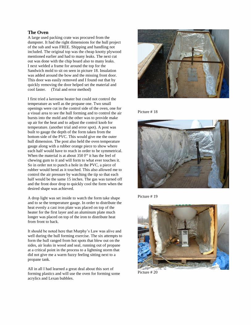
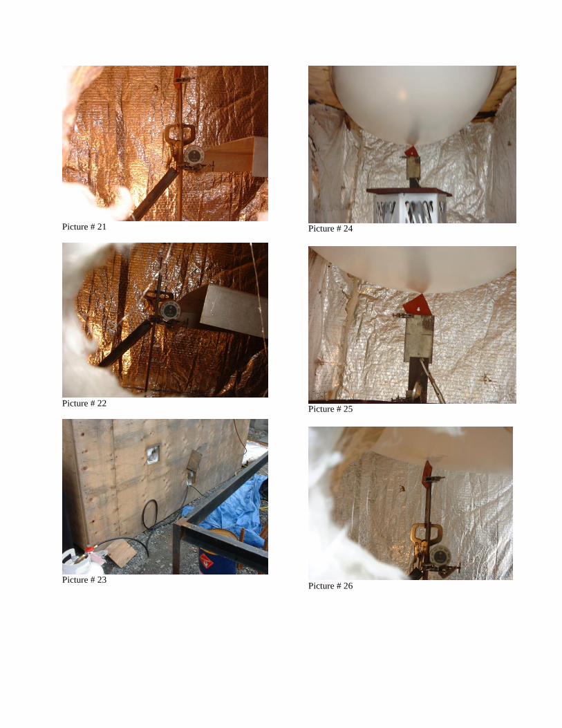