Embed Size (px)
Citation preview
PRODUCT CATALOG
CAT. No.129A
SURGE ABSORBERS
SENSORS AND MODULES
THERMISTORS
3
THERMISTOR
POWER THERMISTOR
VRD (TRANSIENT VOLTAGE SUPPRESSOR)
CRD (CURRENT REGULATIVE DIODE)
ZENAMIC (METAL OXIDE VARISTOR)
GAS TUBE ARRESTER
DIGITAL TEMPERATURE SENSOR MODULE
4
20
24
28
30
38
42
HIGH PRECISION SERIESSMD SERIESHIGH HEAT-RESISTANCE SERIESDISK SERIESSENSORS
POWER THERMISTOR SERIESMARK SERIES
SMD SERIESLEAD TYPE SERIES
LEAD TYPE SERIES
MELF TYPE SERIES
LEAD TYPE SERIESM TYPE SERIESSURGE ABSORBER UNIT SERIES
CERAMIC TUBE SERIESGLASS TUBE SERIESSA-01 SERIES
DM1 SERIES
4
2.1 2.2 2.3 2.4 2.5 2.6 2.7 2.8 2.9 3.0 3.1 3.2 3.3 3.4 3.5 3.6 3.7 3.8 3.9
B:3350
B:3400
B:365
0
1k
10k
100k
Res
ista
nce(
V)
Temperature(1/ Tx103)
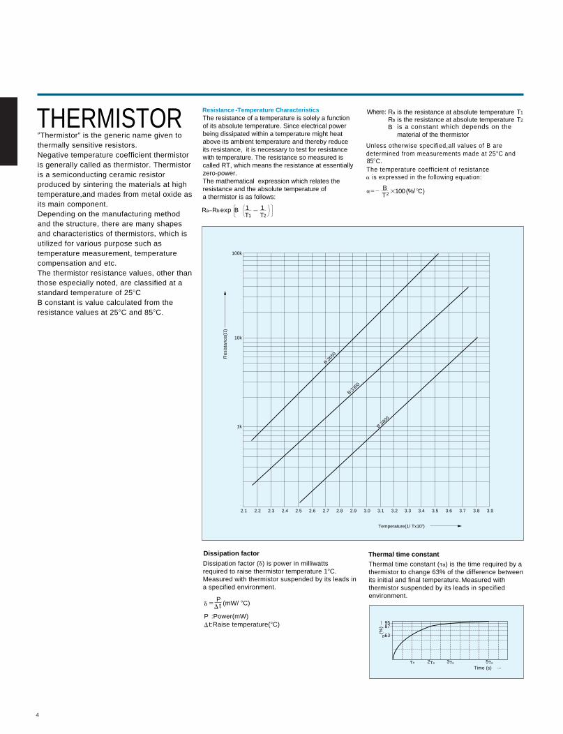
THERMISTOR0Thermistor0 is the generic name given tothermally sensitive resistors.Negative temperature coefficient thermistoris generally called as thermistor. Thermistoris a semiconducting ceramic resistorproduced by sintering the materials at hightemperature,and mades from metal oxide asits main component. Depending on the manufacturing methodand the structure, there are many shapesand characteristics of thermistors, which isutilized for various purpose such astemperature measurement, temperaturecompensation and etc.The thermistor resistance values, other thanthose especially noted, are classified at astandard temperature of 258CB constant is value calculated from theresistance values at 258C and 858C.
The resistance of a temperature is solely a functionof its absolute temperature. Since electrical powerbeing dissipated within a temperature might heatabove its ambient temperature and thereby reduceits resistance, it is necessary to test for resistancewith temperature. The resistance so measured iscalled RT, which means the resistance at essentiallyzero-power.The mathematical expression which relates theresistance and the absolute temperature ofa thermistor is as follows:
Ra5Rb exp B 1T1
1T2
BT2
2
Ra T1Where: is the resistance at absolute temperatureis the resistance at absolute temperatureRb T2
B is a constant which depends on thematerial of the thermistor
Unless otherwise specified,all values of B aredetermined from measurements made at 258C and858C.The temperature coefficient of resistancea is expressed in the follow ing equation:
3100(%/ 8C)a52
Resistance -Temperature Characteristics
Dissipation factor Thermal time constantDissipation factor (d) is power in milliwattsrequired to raise thermistor temperature 18C.Measured with thermistor suspended by its leads ina specified environment.
d 5
t:Raise temperature(8C)
t
t
P (mW/ 8C)
P :Power(mW)
Thermal time constant (ta) is the time required by athermistor to change 63% of the difference betweenits initial and final temperature.Measured withthermistor suspended by its leads in specifiedenvironment.
9587
63
ta 2ta 3ta 5ta
Time (s)
(%)
D
D
D
5
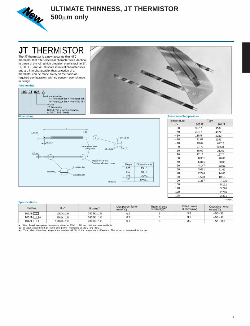
JT THERMISTORThe JT thermistor is a new accurate thin NTCthermistor that offer electrical characteristics identicalto tho se of the AT, a high precision themistor,The JT, IT, HT, ET, and AT all share identical characteristicsand are interchangeable, thus selection of athermistor can be made solely on the basis ofrequired configuration, with no concern over changein design.
Part number
103 JT-025 A
Shape
Insulation film
Rated zero-power resistance at 258C 103 : 10kV
JT thermistor
Dimensions
A
3.660.5 561
2.060.5
0.560.035
0.1760.02
1.860.1
Unit(mm)
0.5max.
Adhesive
lnsulation film
lnsulation film
Solder plated wires42 Alloy leads
Slipped film : 1 max.Protruded adhesive : 1 max.
Shape Dimensions A
025 2561
5061
7561
10061
050
075
100
Specifications
Type
Resistance-Temperature
Temperature(8C)
Unit(kV)
250
240
230
220
2100
102030405060708090
100110120125
367.7204.7118.571.0243.6727.7018.0712.118.3015.8114.1473.0112.2241.6681.267
103JT 104JT
Part No. R25*1 B value*2 Dissipation factor(mW/ 8C)
Thermal time constant(s)*3
Operating temp.range(8C)
Rated powerat 258C(mW)
*1 R25 : Rated zero-power resistance value at 258C, 62% and 3% are also available.
*2 B value : determined by rated zero-power resistance at 258C and 858C.
*3 Time when thermistor temperature reaches 63.2% of the temperature difference. The value is measured in the air.
103JT-103JT-104JT-
10kV61%10kV61%
100kV61%
3435K61%3435K61%4390K61%
0.70.70.7
55
5
3.53.53.5
250;90
250;90250;125
A : Polyester film3Polyester filmNil:Polyester film3Polyimide film
9584457222821191
647.2365.0212.5127.778.8850.0332.5121.6114.6610.137.1355.1113.7202.7462.371
A
ULTIMATE THINNESS, JT THERMISTOR500mm only
1.0Tiebar cut
4.0
max
.
2.5460.25
8.56
1
176
1.5
Color code
Epoxy
Unit mm
0.5 Tim-Plated42 Alloy
2.4 max.
2.4 max.3.8 max.
15 max.
Marking0.3sq TPE lead wire
4.0
max
.
5 m
ax.
2.5460.25
561
8.56
166
0.2 4.16
0.2
1.76
0.1
176
1.5
0.7
Tiebar cut
3.8 max.
Epoxy
Color code
0.5 Tim-Plated42 Alloy
Soldered
600 1200
8max.
Epoxy
32.5m
ax. Lead wire AWG30
40;100
AT-2
AT-11
AT-3
AT-4
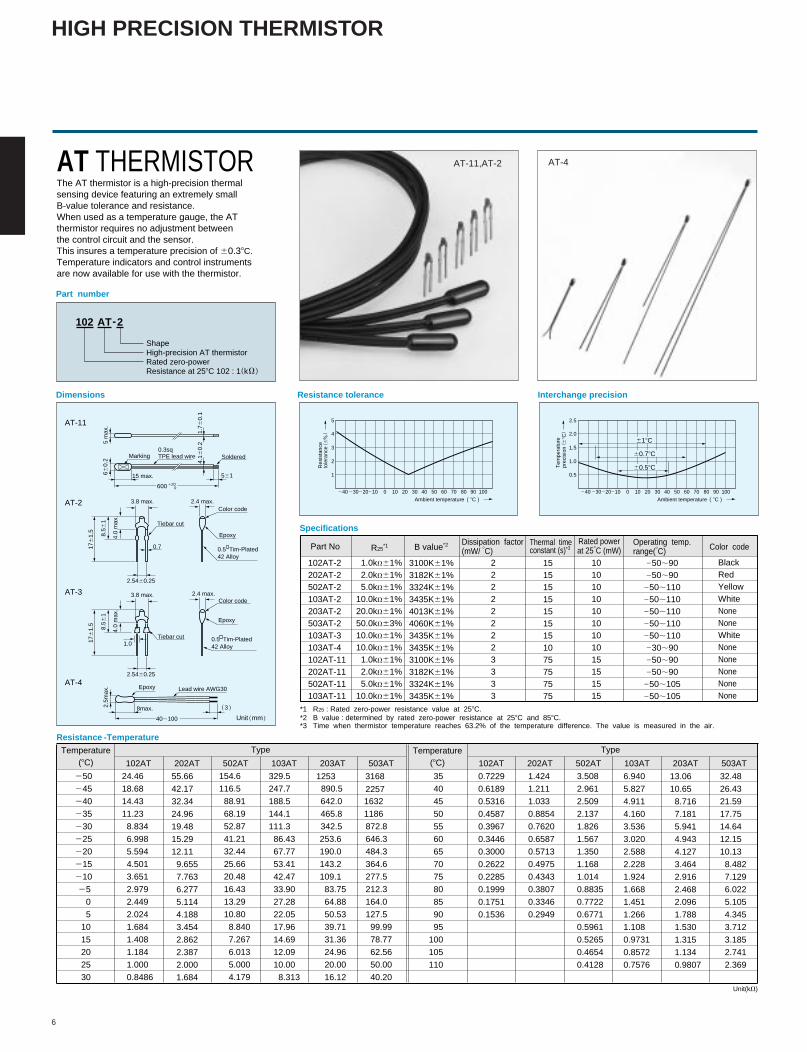
AT THERMISTORThe AT thermistor is a high-precision thermal sensing device featuring an extremely small B-value tolerance and resistance.When used as a temperature gauge, the AT thermistor requires no adjustment between the control circuit and the sensor. This insures a temperature precision of 60.38C.Temperature indicators and control instruments are now available for use with the thermistor.
102 AT-2
ShapeHigh-precision AT thermistorRated zero-powerResistance at 258C 102 : 1 k
Dimensions Resistance tolerance Interchange precision
Part number
Specifications
Resistance -Temperature
240 230220210 0 10 20 30 40 50 60 70 80 90 100
Res
ista
nce
tole
ranc
e 6
5
4
3
2
1
Ambient temperature 8C
Tem
pera
ture
prec
isio
n 6
8C
2.5
2.0
1.5
1.0
0.560.58C
60.78C
618C
102AT-2202AT-2502AT-2103AT-2203AT-2503AT-2103AT-3103AT-4102AT-11202AT-11502AT-11103AT-11
1.0kV61%2.0kV61%5.0kV61%
10.0kV61%20.0kV61%50.0kV63%10.0kV61%10.0kV61%1.0kV61%2.0kV61%5.0kV61%
10.0kV61%
3100K61%3182K61%3324K61%3435K61%4013K61%4060K61%3435K61%3435K61%3100K61%3182K61%3324K61%3435K61%
222222223333
151515151515151075757575
101010101010101015151515
250;90250;90
250;110250;110250;110250;110250;110230;90250;90250;90
250;105250;105
BlackRedYellowWhiteNone None WhiteNoneNone None None None
Part No R25*1 B value*2 Dissipation factor
(mW/ 8C)Thermal time constant (s)*3
Operating temp.range(8C) Color code
Rated powerat 258C (mW)
*1 R25 : Rated zero-power resistance value at 258C.*2 B value : determined by rated zero-power resistance at 258C and 858C.*3 Time when thermistor temperature reaches 63.2% of the temperature difference. The value is measured in the air.
24.46
18.68
14.43
11.23
8.834
6.998
5.594
4.501
3.651
2.979
2.449
2.024
1.684
1.408
1.184
1.000
0.8486
55.66
42.17
32.34
24.96
19.48
15.29
12.11
9.655
7.763
6.277
5.114
4.188
3.454
2.862
2.387
2.000
1.684
154.6
116.5
88.91
68.19
52.87
41.21
32.44
25.66
20.48
16.43
13.29
10.80
8.840
7.267
6.013
5.000
4.179
329.5
247.7
188.5
144.1
111.3
86.43
67.77
53.41
42.47
33.90
27.28
22.05
17.96
14.69
12.09
10.00
8.313
642.0
465.8
342.5
253.6
190.0
143.2
109.1
83.75
64.88
50.53
39.71
31.36
24.96
20.00
16.12
1632
1186
872.8
646.3
484.3
364.6
277.5
212.3
164.0
127.5
99.99
78.77
62.56
50.00
40.20
250
245
240
235
230
225
220
215
210
25
0
5
10
15
20
25
30
35
40
45
50
55
60
65
70
75
80
85
90
95
100
105
110
0.7229
0.6189
0.5316
0.4587
0.3967
0.3446
0.3000
0.2622
0.2285
0.1999
0.1751
0.1536
1.424
1.211
1.033
0.8854
0.7620
0.6587
0.5713
0.4975
0.4343
0.3807
0.3346
0.2949
3.508
2.961
2.509
2.137
1.826
1.567
1.350
1.168
1.014
0.8835
0.7722
0.6771
0.5961
0.5265
0.4654
0.4128
6.940
5.827
4.911
4.160
3.536
3.020
2.588
2.228
1.924
1.668
1.451
1.266
1.108
0.9731
0.8572
0.7576
13.06
10.65
8.716
7.181
5.941
4.943
4.127
3.464
2.916
2.468
2.096
1.788
1.530
1.315
1.134
0.9807
102AT 202AT 502AT 103AT 203AT 503AT
Temperature(8C)
Temperature(8C) 102AT 202AT 502AT 103AT 203AT 503AT
Unit(kV)
32.48
26.43
21.59
17.75
14.64
12.15
10.13
8.482
7.129
6.022
5.105
4.345
3.712
3.185
2.741
2.369
Type Type
1253890.5
3168
2257
240 230220210 0 10 20 30 40 50 60 70 80 90 100
Ambient temperature 8C
6
AT-11,AT-2 AT-4
HIGH PRECISION THERMISTOR
0.3
2N
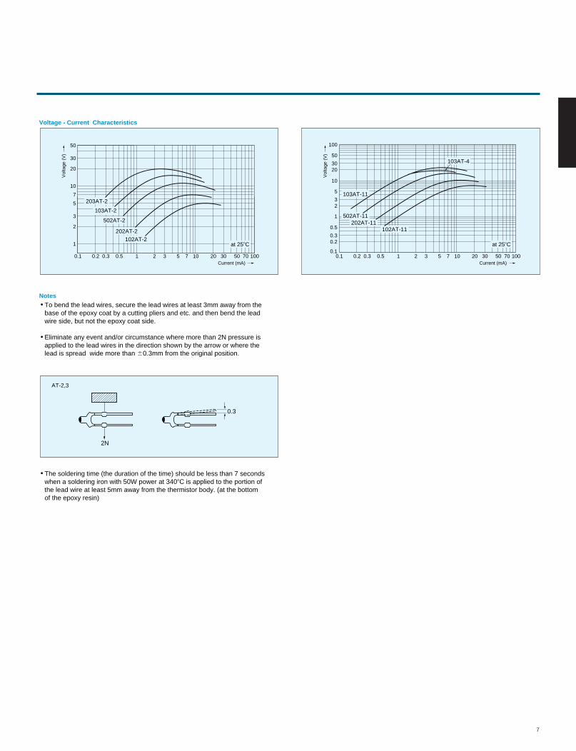
To bend the lead wires, secure the lead wires at least 3mm away from the base of the epoxy coat by a cutting pliers and etc. and then bend the lead wire side, but not the epoxy coat side.
Eliminate any event and/or circumstance where more than 2N pressure is applied to the lead wires in the direction shown by the arrow or where the lead is spread wide more than 60.3mm from the original position.
Voltage - Current Characteristics
Notes
Current (mA)
Vol
tage
(V
)
10
0.1 0.2 0.3 0.5 1 2 3 5 7 10 20 30 50 70 100
20
30
50
1
2
3
5
7203AT-2
203AT-2103AT-2
502AT-2
202AT-2102AT-2
at 258C
Current (mA)
Vol
tage
(V
)
10
0.1 0.2 0.3 0.5 1 2 3 5 7 10 20 30 50 70 100
1
23
5
100
2030
50
0.1
0.20.3
0.5 102AT-11
103AT-11
103AT-4
502AT-11202AT-11
at 258C
The soldering time (the duration of the time) should be less than 7 secondswhen a soldering iron with 50W power at 3408C is applied to the portion of the lead wire at least 5mm away from the thermistor body. (at the bottomof the epoxy resin)
AT-2,3
7
8
4 max.
4 max.
f1.
5 m
ax.
f1.
6 m
ax.
3624622161
8761
4561
Resin(black)
Resin (ET-2 : light brown, ETB : black)
Soldered terminal
Resin
(0.17)
(0.25)
Enlarged view
Solder plated lead wires(resin coated insulation)
Solder plated lead wires
(0.17)
(0.25)
Enlarged view
ET-2, ETB
ET-1
Part number
Dimensions
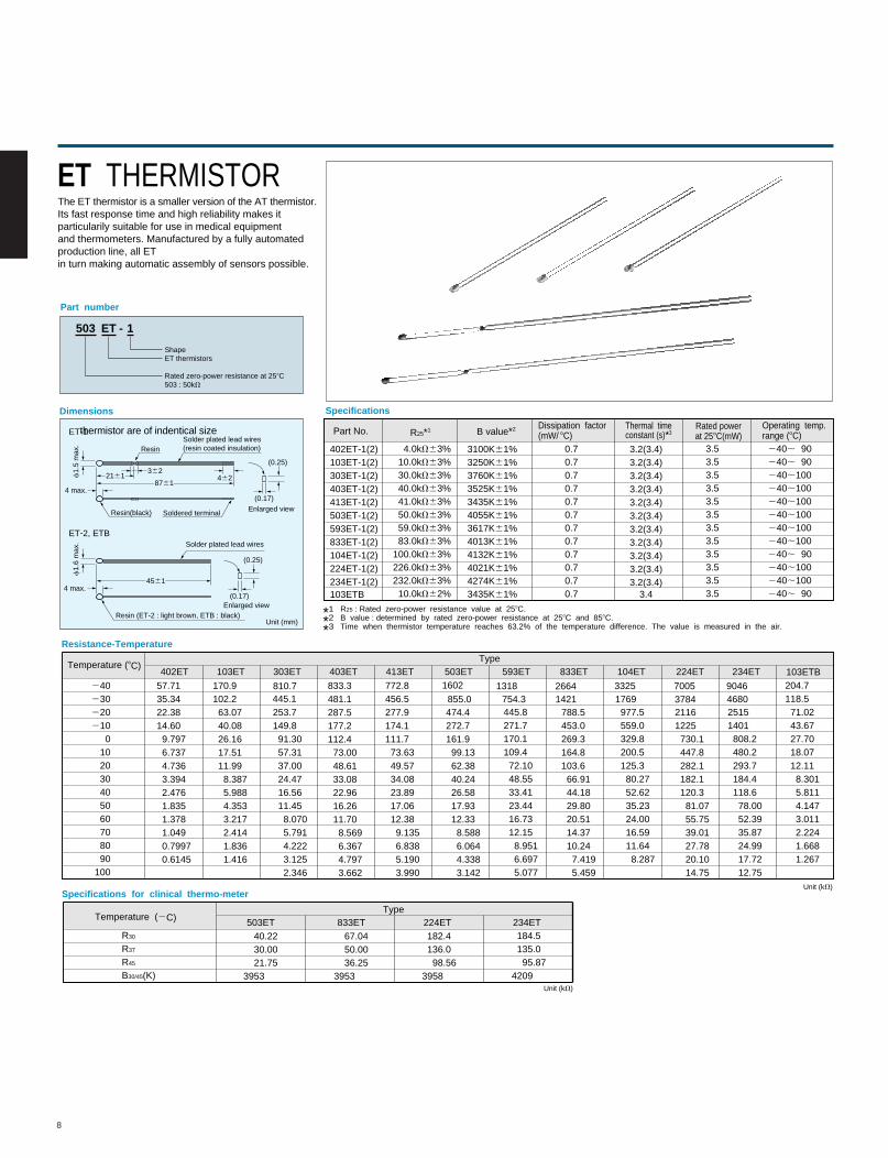
ET THERMISTORThe ET thermistor is a smaller version of the AT thermistor.Its fast response time and high reliability makes itparticularily suitable for use in medical equipmentand thermometers. Manufactured by a fully automatedproduction line, all ET
thermistor are of indentical size
in turn making automatic assembly of sensors possible.
503 ET 1-
ET thermistorsShape
Rated zero-power resistance at 258C503 : 50kV
Specifications
Part No. R25*1 B value*2 Dissipation factor(mW/ 8C)
Thermal time constant (s)*3
Operating temp.range (8C)
Rated powerat 258C(mW)
*1 R25 : Rated zero-power resistance value at 258C.
*2 B value : determined by rated zero-power resistance at 258C and 858C.
*3 Time when thermistor temperature reaches 63.2% of the temperature difference. The value is measured in the air.
402ET-1(2) 103ET-1(2)303ET-1(2)403ET-1(2)413ET-1(2)503ET-1(2)593ET-1(2)833ET-1(2)104ET-1(2)224ET-1(2)234ET-1(2)103ETB
4.0kV63%10.0kV63%30.0kV63%40.0kV63%41.0kV63%50.0kV63%59.0kV63%83.0kV63%
100.0kV63%226.0kV63%232.0kV63%
10.0kV62%
3100K61%3250K61%3760K61%3525K61%3435K61%4055K61%3617K61%4013K61%4132K61%4021K61%4274K61%3435K61%
0.70.70.70.70.70.70.70.70.70.70.70.7
3.53.53.53.53.53.53.53.53.53.53.53.5
3.2(3.4)3.2(3.4)3.2(3.4)3.2(3.4)3.2(3.4)3.2(3.4)3.2(3.4)3.2(3.4)3.2(3.4)3.2(3.4)3.2(3.4)
3.4
240; 90240; 90240;100240;100240;100240;100240;100240;100240; 90240;100240;100240; 90
Temperature (8C)Type
Resistance-Temperature
Unit (kV)
Unit (kV)
240230220210
0102030405060708090
100
57.7135.3422.3814.609.7976.7374.7363.3942.4761.8351.3781.0490.79970.6145
170.9102.263.0740.0826.1617.5111.998.3875.9884.3533.2172.4141.8361.416
253.7149.891.3057.3137.0024.4716.5611.458.0705.7914.2223.1252.346
833.3481.1287.5177.2112.473.0048.6133.0822.9616.2611.708.5696.3674.7973.662
772.8456.5277.9174.1111.773.6349.5734.0823.8917.0612.389.1356.8385.1903.990
474.4272.7161.999.1362.3840.2426.5817.9312.338.5886.0644.3383.142
445.8271.7170.1109.472.1048.5533.4123.4416.7312.158.9516.6975.077
788.5453.0269.3164.8103.666.9144.1829.8020.5114.3710.247.4195.459
977.5559.0329.8200.5125.380.2752.6235.2324.0016.5911.648.287
21161225730.1447.8282.1182.1120.381.0755.7539.0127.7820.1014.75
25151401808.2480.2293.7184.4118.678.0052.3935.8724.9917.7212.75
204.7118.571.0243.6727.7018.0712.118.3015.8114.1473.0112.2241.6681.267
402ET 103ET 303ET 403ET 413ET 503ET 593ET 833ET 104ET 224ET 234ET 103ETB
Specifications for clinical thermo-meter
Temperature (2C)Type
40.2230.0021.75
3953
67.0450.0036.25
3953
182.4136.098.56
3958
184.5135.095.87
4209
R30
R37
R45
B30/45(K)
503ET 833ET 224ET 234ET
Unit (mm)
1602
855.01318
754.326641421
33251769
70053784
90464680
810.7445.1
9
Part number
Dimensions
Taping
Package
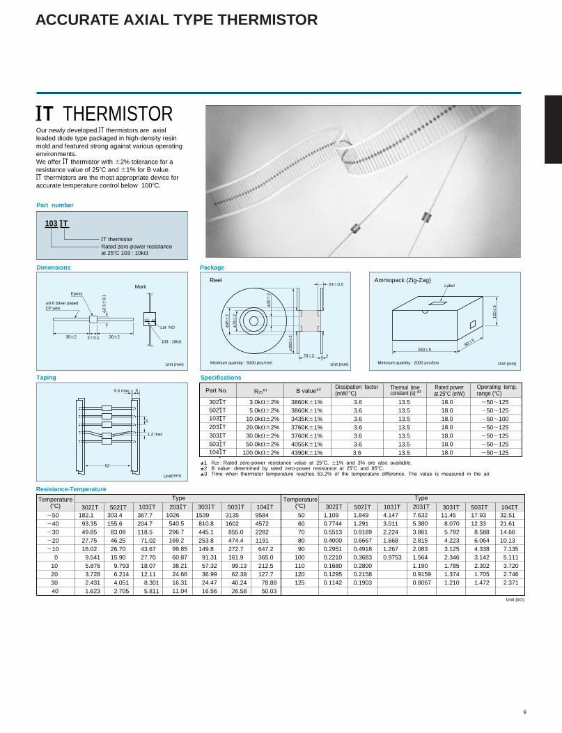
Our newly developed IT thermistors are axialleaded diode type packaged in high-density resinmold and featured strong against various operatingenvironments.We offer IT thermistor with 62% tolerance for aresistance value of 258C and 61% for B value.IT thermistors are the most appropriate device foraccurate temperature control below 1008C.
103 I T
IT thermistorRated zero-power resistance at 258C 103 : 10kV
MarkReel Ammopack (Zig-Zag)
Epoxy
f0.6 Silver platedCP wire
f2.
560.
1
f95
62
f76
62
7062
1006
5
260658065
2460.5
f30
62
f35
0623062 3062360.1
103 AA
Lot NO
103 : 10kV
Unit (mm)
(mm)
Unit (mm) Unit (mm)
2
5
6
1.2 max
0.5 max.
Minimum quantity : 5000 pcs/reel Minimum quantity : 2000 pcs/box
Label
52
182.193.3549.8527.7516.029.5415.8763.7282.4311.623
303.4155.683.0946.2526.7015.909.7936.2144.0512.705
367.7204.7118.571.0243.6727.7018.0712.118.3015.811
1539810.8445.1253.8149.891.3157.3236.9924.4716.56
31351602855.0474.4272.7161.999.1362.3840.2426.58
9584457222821191647.2365.0212.5127.778.8850.03
1026540.5296.7169.299.8560.8738.2124.6616.3111.04
Specifications
Part No. R25*1 B value*2 Dissipation factor(mW/ 8C)
Thermal time constant (s) *3
Operating temp.range (8C)
Rated powerat 258C (mW)
*1 R25 : Rated zero-power resistance value at 258C, 61% and 3% are also available.
*2 B value : determined by rated zero-power resistance at 258C and 858C.
*3 Time when thermistor temperature reaches 63.2% of the temperature difference. The value is measured in the air.
302 I T 3.0kV62%5.0kV62%
10.0kV62%20.0kV62%30.0kV62%50.0kV62%
100.0kV62%
3860K61%3860K61%3435K61%3760K61%3760K61%4055K61%4390K61%
3.63.63.63.63.63.63.6
13.513.513.513.513.513.513.5
18.018.018.018.018.018.018.0
250;125250;125250;100250;125250;125250;125250;125
Resistance-Temperature
250240230220210
0102030
40
Temperature(8C)
Temperature(8C)
1.1090.77440.55130.40000.29510.22100.16800.12950.1142
5060708090
100110120125
1.8491.2910.91890.66670.49180.36830.28000.21580.1903
4.1473.0112.2241.6681.2670.9753
7.6325.3803.8612.8152.0831.5641.1900.91590.8067
11.458.0705.7924.2233.1252.3461.7851.3741.210
17.9312.338.5886.0644.3383.1422.3021.7051.472
32.5121.6114.6610.137.1355.1113.7202.7462.371
Unit (kV)
IT THERMISTOR
Unit
502I T103I T
104 I T503I T
302I T 502I T 103I T 203I T 303I T 503I T 104I T 302I T 502I T 203I T 303I T 503I T 104I T103I T
303I T203I T
Type Type
ACCURATE AXIAL TYPE THERMISTOR
10
1.660.15
2.6560.2
3.8060.150.0260.05 1.160.150.660.2/20
103
Dimensions Dimensions
Taping Taping
Dimensions
Taping
42 AlloyEpoxy resinMark
1.660.15
3.060.3
0.3
0.81.160.15
2.6560.2
8.6560.5
5.2560.11.7
103
Mark
Epoxy resin
Solder platedlead wires42 Alloy
0.660.1
0.1760.1
0.8
0.6
Unit (mm)
Part number
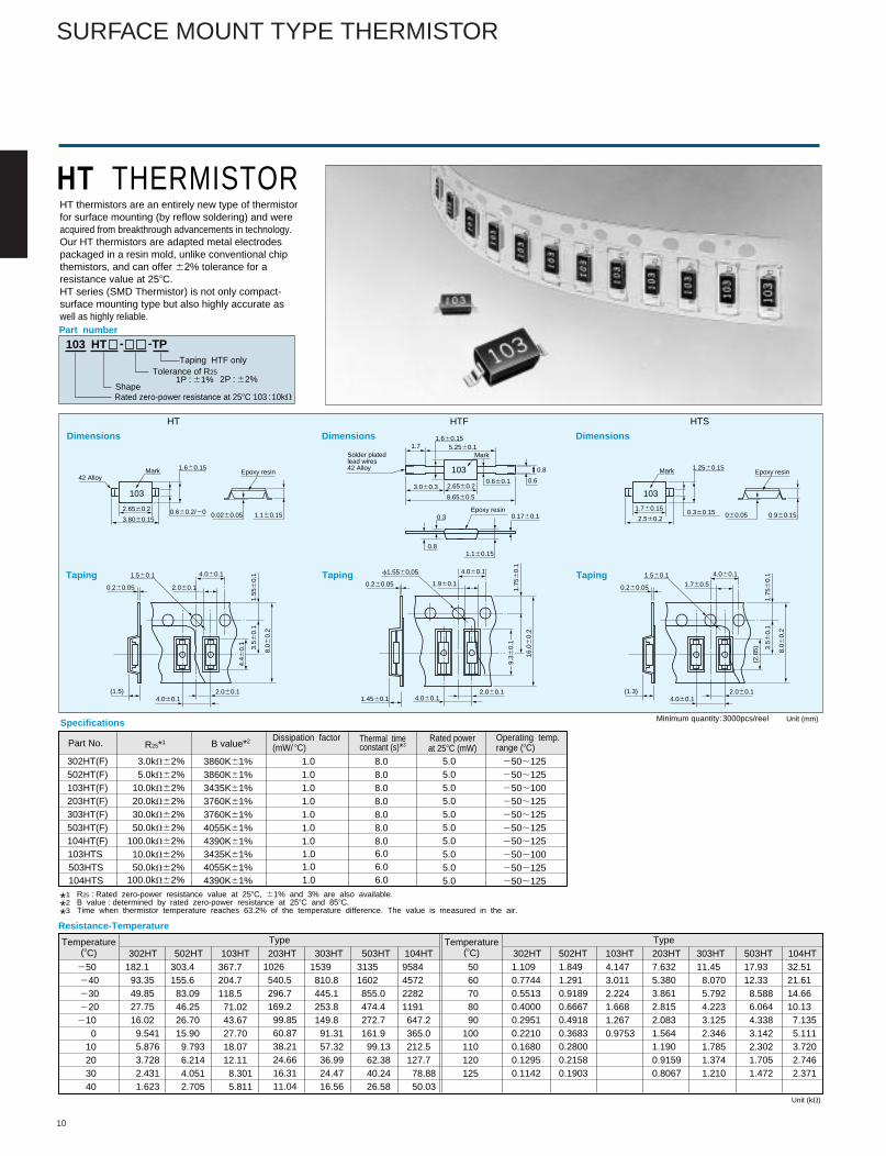
HT THERMISTOR
103 HT
Shape
Tolerance of R25
Taping HTF only
Rated zero-power resistance at 258C 103 : 10kV
HT thermistors are an entirely new type of thermistorfor surface mounting (by reflow soldering) and wereacquired from breakthrough advancements in technology.Our HT thermistors are adapted metal electrodespackaged in a resin mold, unlike conventional chipthemistors, and can offer 62% tolerance for aresistance value at 258C.HT series (SMD Thermistor) is not only compact-surface mounting type but also highly accurate aswell as highly reliable.
182.193.3549.8527.7516.029.5415.8763.7282.4311.623
303.4155.683.0946.2526.7015.909.7936.2144.0512.705
367.7204.7118.571.0243.6727.7018.0712.118.3015.811
1539810.8445.1253.8149.891.3157.3236.9924.4716.56
31351602855.0474.4272.7161.999.1362.3840.2426.58
9584457222821191647.2365.0212.5127.778.8850.03
1026540.5296.7169.299.8560.8738.2124.6616.3111.04
Specifications
Part No. R25*1 B value*2 Dissipation factor(mW/ 8C)
Thermal time constant (s)*3
Operating temp.range (8C)
Rated powerat 258C (mW)
*1 R25 : Rated zero-power resistance value at 258C, 61% and 3% are also available.
*2 B value : determined by rated zero-power resistance at 258C and 858C.
*3 Time when thermistor temperature reaches 63.2% of the temperature difference. The value is measured in the air.
302HT(F)502HT(F)103HT(F)203HT(F)303HT(F)503HT(F)104HT(F)
3.0kV62%5.0kV62%
10.0kV62%20.0kV62%30.0kV62%50.0kV62%
100.0kV62%
3860K61%3860K61%3435K61%3760K61%3760K61%4055K61%4390K61%
1.01.01.01.01.01.01.0
8.08.08.08.08.08.08.0
5.05.05.05.05.05.05.05.05.05.0
250;125250;125250;100250;125250;125250;125250;125250;100250;125250;125
Resistance-Temperature
250240230220210
010203040
Type302HT 502HT 103HT 203HT 303HT 503HT
Type302HT 502HT 103HT 203HT 303HT 503HT 104HT
Temperature(8C)
Temperature(8C)
1.1090.77440.55130.40000.29510.22100.16800.12950.1142
5060708090
100110120125
1.8491.2910.91890.66670.49180.36830.28000.21580.1903
4.1473.0112.2241.6681.2670.9753
7.6325.3803.8612.8152.0831.5641.1900.91590.8067
11.458.0705.7924.2233.1252.3461.7851.3741.210
17.9312.338.5886.0644.3383.1422.3021.7051.472
32.5121.6114.6610.137.1355.1113.7202.7462.371
Unit (kV)
4.060.1
1.960.1
4.060.11.4560.12.060.1
1.75
60.
1
16.0
60.
2
0.260.05
f1.5560.05
1.760.51.560.1
2.060.1
4.060.1
4.060.12.060.1
3.56
0.1
1.55
60.
1
8.0 6
0.2
0.260.05
(1.5)
4.46
0.1
1.2560.15
1.760.15
2.560.2 060.050.360.15 0.960.15
103
Epoxy resinMark
1.560.1 4.060.1
4.060.12.060.1
3.56
0.1
1.75
60.
1
8.0 6
0.2
0.260.05
(1.3)
104HT
-TP-
1P : 61% 2P : 62%
103HTS503HTS104HTS
10.0kV62%50.0kV62%
100.0kV62%
3435K61%4055K61%4390K61%
1.01.01.0
6.06.06.0
HT HTF HTS
(2.8
5)
9.36
0.1
Minimum quantity:3000pcs/reel
SURFACE MOUNT TYPE THERMISTOR
11
0.74
60.
03
0.86
0.1
0.25
60.
03
0.660.1
1.660.1
0.4760.03 0.4760.03
Part number
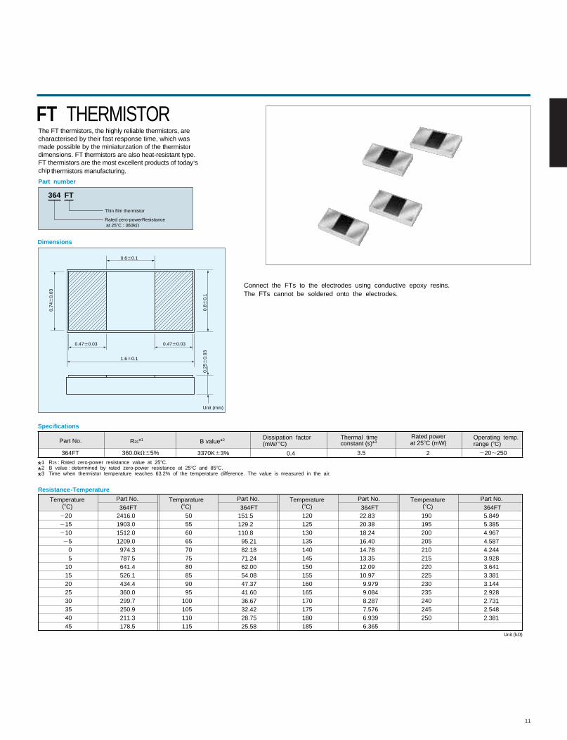
Dimensions
FT THERMISTORThe FT thermistors, the highly reliable thermistors, are characterised by their fast response time, which was made possible by the miniaturzation of the thermistor dimensions. FT thermistors are also heat-resistant type.FT thermistors are the most excellent products of today,s chip thermistors manufacturing.
364 FT
Thin film thermistor
Rated zero-powerResistance at 258C : 360kV
Part No.Temperature(8C)
Resistance-Temperature
364FT
Part No.Temparature(8C) 364FT
Part No.Temperature(8C) 364FT
Part No.Temperature(8C) 364FT
22021521025
05
1015202530354045
50556065707580859095
100105110115
120125130135140145150155160165170175180185
190195200205210215220225230235240245250
2416.01903.01512.01209.0 974.3 787.5 641.4 526.1 434.4 360.0 299.7 250.9 211.3 178.5
151.5129.2110.895.2182.1871.2462.0054.0847.3741.6036.6732.4228.7525.58
22.8320.3818.2416.4014.7813.3512.0910.979.9799.0848.2877.5766.9396.365
5.8495.3854.9674.5874.2443.9283.6413.3813.1442.9282.7312.5482.381
Specifications
Part No. R25*1 B value*2 Dissipation factor(mW/ 8C)
Thermal time constant (s)*3
Operating temp.range (8C)
Rated powerat 258C (mW)
*1 R25 : Rated zero-power resistance value at 258C.
*2 B value : determined by rated zero-power resistance at 258C and 858C.
*3 Time when thermistor temperature reaches 63.2% of the temperature difference. The value is measured in the air.
364FT 360.0kV65% 3370K63% 0.4 3.5 2 220;250
Unit (mm)
Unit (kV)
Connect the FTs to the electrodes using conductive epoxy resins.The FTs cannot be soldered onto the electrodes.
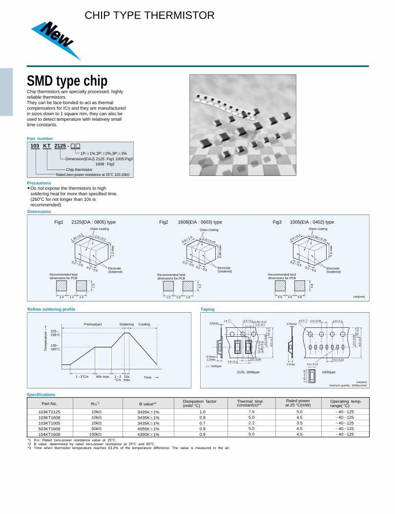
SMD type chip Chip thermistors are specially processed, highlyreliable thermistors. They can be face-bonded to act as thermal compensators for ICs and they are manufacturedin sizes down to 1 square mm, they can also be used to detect temperature with relatively smalltime constants.
Precautions
Dimensions
Reflow soldering profile Taping
103 KT 2125 -
Rated zero-power resistance at 25�C 103:10k�
Part number
Chip thermistor
1P:�1%,2P:�2%,3P:�3%Dimension(EIAJ) 2125: Fig1 1005:Fig3
Specifications
Part No. R25*1 B value*2 Dissipation factor
(mW/ �C)Thermal time constant(s)*3
Operating temp.range( �C)
Rated powerat 25 �C(mW)
*1 R25 : Rated zero-power resistance value at 25�C.*2 B value : determined by rated zero-power resistance at 25�C and 85�C.*3 Time when thermistor temperature reaches 63.2% of the temperature difference. The value is measured in the air.
103KT2125103KT1608103KT1005503KT1608104KT1608
10k�
10k�
10k�
50k�
100k�
3435K�1%3435K�1%3435K�1%4055K�1%4390K�1%
1.00.90.70.90.9
7.55.02.25.05.0
5.04.53.54.54.5
�40�125�40�125�40�125�40�125�40�125
2125(EIA : 0805) typeFig1 Fig2 1608(EIA : 0603) type
Do not expose the thermistors to high soldering heat for more than specified time. (260�C for not longer than 10s is recommended)
1.3 1.1 1.3
1.5
Recommended landdimensions for PCB
1.0 1.0 1.0
1.2
Unit(mm)
Recommended landdimensions for PCB
2.0�0.2
0.2�0.5
0.2�0.5
1.2
max
.
1.25�0.2
Glass coating
Electrode(Soldered)
1005(EIA : 0402) typeFig3
0.6 0.5 0.6
0.6
Recommended landdimensions for PCB
1.00�0.15
0.2�0.5
0.2�0.5
0.6
max
.
0.5�0.1
Glass coating
Electrode(Soldered)
1.6�0.15
0.2�0.5
0.2�0.5
0.95
max
.
0.8�1.5
Glass coating
Electrode(Soldered)
130�160�C
225�235�C
Tem
pera
ture
Time
Soldering CoolingPreheat(air)
1�3�C/s 1�2�C/s
60s max. 10s max.
1608 : Fig2
unit(mm)minimum quantity : 4000pcs/reel
1.5 (1.65�0.2)1.0�0.1
4.0�0.1
4.0�0.12.0�0.05
3.5�
0.05 1.
75�
0.1
8.0�
0.3
(2.0max.)1.2max.
( ) : 1608type
0.6max.�0.1
0
(2.4
�0.
2)1.
85�
0.1
4.0�0.1
3.5�
0.05 1.
75�
0.1
8.0�
0.3
�1.5�0.1 0
2.0�0.10
0.6�0.10
1.10
�0.
10
2.0�0.050.25max
1.0max
1005type2125, 1608type
CHIP TYPE THERMISTOR
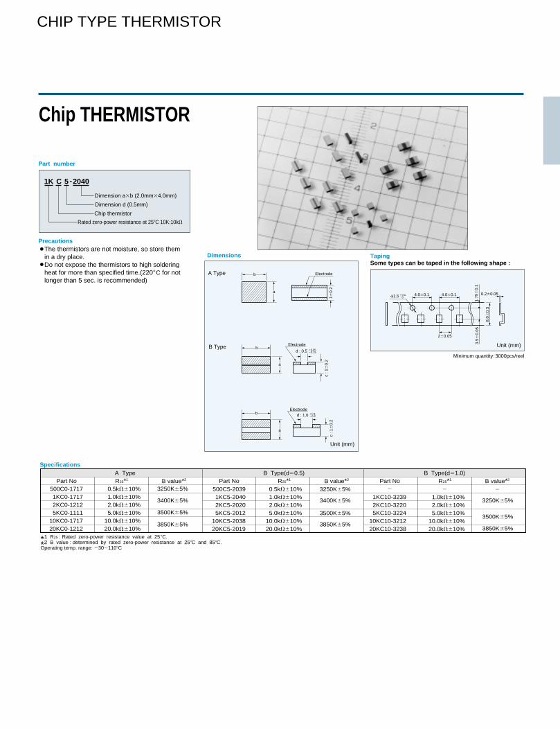
Chip THERMISTOR
The thermistors are not moisture, so store them in a dry place. Do not expose the thermistors to high soldering heat for more than specified time.(220�C for not longer than 5 sec. is recommended)
1K C 5 -2040
Part number
Precautions
4.0�0.1
c : 1
�0.
2c
: 1�
0.2
1�0.
2
4.0�0.1 0.2�0.05
2�0.05
3.5�
0.05
1.75
�0.
1
8.0�
0.3
�1.5 �0.1�0
d : 1.0 �0.1�0.2
d : 0.5 �0.05�0.15
a
b
a
Electrode
Electrode
Electrode
b
a
bA Type
B Type
Dimensions TapingSome types can be taped in the following shape :
SpecificationsA Type B Type(d�0.5) B Type(d�1.0)R25*1 B value*2
*1 R25 : Rated zero-power resistance value at 25 �C.
*2 B value : determined by rated zero-power resistance at 25�C and 85�C.Operating temp. range: �30�110�C
Part No R25*1 B value*2Part No R25*1 B value*2Part No500C0-17171KC0-17172KC0-12125KC0-1111
10KC0-171720KC0-1212
500C5-20391KC5-20402KC5-20205KC5-2012
10KC5-203820KC5-2019
1KC10-32392KC10-32205KC10-3224
10KC10-321220KC10-3238
0.5k��10%1.0k��10%2.0k��10%5.0k��10%
10.0k��10%20.0k��10%
1.0k��10%2.0k��10%5.0k��10%
10.0k��10%20.0k��10%
0.5k��10%1.0k��10%2.0k��10%5.0k��10%
10.0k��10%20.0k��10%
� �
3250K�5%
3500K�5%
3850K�5%
3400K�5%
3250K�5%
3500K�5%
3850K�5%
3400K�5%
3250K�5%
3500K�5%
3850K�5%
Unit (mm)
Unit (mm)
Chip thermistor
Dimension d (0.5mm)
Dimension ab (2.0mm4.0mm)
Rated zero-power resistance at 25�C 10K:10k�
�
Minimum quantity:3000pcs/reel
CHIP TYPE THERMISTOR
14
361
1.35
60.
15
4861
Glass
Nickel-plated
(0.15)
(0.1
8)
Part number
Time constant
Dimensions
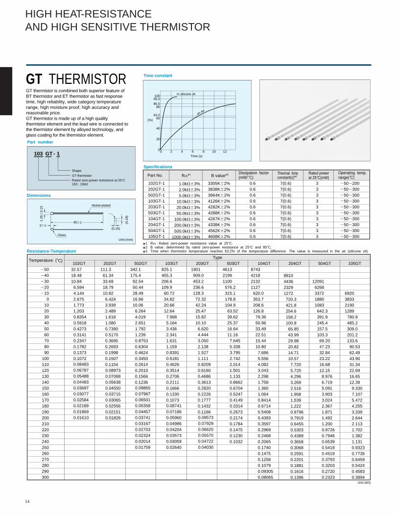
GT THERMISTORGT thermistor is combined both superior feature of BT thermistor and ET thermistor as fast response time, high reliability, wide category temperature range, high moisture proof, high accuracy and reasonable price.GT thermistor is made up of a high qualitythermistor element and the lead wire is connected tothe thermistor element by alloyed technology, andglass coating for the thermistor element.
103 GT 1-
GT thermistor
Shape
Rated zero-power resistance at 258C103 : 10kV
10095.0
86.580
63.260
40
20
00 2 4 6 8 10 12
(%)
Time (s)
on Air
in silicone oil
Specifications
Part No. R25*1 B value*2 Dissipation factor(mW/ 8C)
Thermal time constant(s)*3
Operating temp.range(8C)
Rated powerat 258C(mW)
*1 R25 : Rated zero-power resistance value at 258C.
*2 B value : determined by rated zero-power resistance at 258C and 858C.
*3 Time when thermistor temperature reaches 63.2% of the temperature difference. The value is measured in the air. (silicone oil)
102GT-1202GT-1502GT-1103GT-1203GT-1503GT-1104GT-1204GT-1504GT-1105GT-1
3305K62%3838K62%3964K62%4126K62%4282K62%4288K62%4267K62%4338K62%4562K62%4608K62%
0.60.60.60.60.60.60.60.60.60.6
3333333333
7(0.6)7(0.6)7(0.6)7(0.6)7(0.6)7(0.6)7(0.6)7(0.6)7(0.6)7(0.6)
250;200250;300250;300250;300250;300250;300250;300250;300250;300250;300
Resistance-Temperature
Temperature (8C)Type
Unit (kV)
102GT 202GT 502GT 103GT 203GT 503GT 104GT 204GT 504GT 105GT250240230220210
0102030405060708090
100110120130140150160170180190200210220230240250260270280290300
32.5718.4810.846.5944.1442.6751.7731.2030.83540.59180.42730.3141
0.23470.17820.13730.1072
111.361.3433.6918.7910.826.4243.9392.4891.6181.0800.73900.51700.36950.26930.19980.15070.1154
342.1175.492.5450.4428.4916.6610.066.2644.0192.6511.7921.2390.87530.63040.46240.34500.26140.20100.15660.1236
825.1405.3206.6109.960.7234.8220.6612.647.9685.1643.4362.3411.6311.1590.83910.61810.46260.35140.27060.21110.16660.13300.1073
1901909.0453.2236.6128.372.3242.2425.4715.8210.106.6204.4443.0502.1381.5271.1110.82090.61600.46860.36130.28200.22260.17770.1432
0.1166
461321991100576.2315.1178.8104.963.5239.6225.3716.6411.167.6455.3383.7952.7422.014 1.5011.1330.86620.67040.52470.41490.33140.26730.21740.17840.14750.12300.1032
8743421821321127620.0353.7208.6126.879.3650.9633.4922.5115.4410.807.6865.5564.0823.0432.2981.7581.3601.0640.84140.67140.54080.43930.35970.29690.24680.20650.17400.14750.12580.10790.093050.08065
8810443623291272720.3421.8254.6158.2100.865.8543.9929.9820.8214.7110.577.7205.7204.2963.2692.5161.9581.5391.2220.97960.79190.64550.53030.43890.36580.30680.25910.22010.18810.16160.1396
120916268337218801083642.3391.9245.4157.5103.369.2047.2332.8423.2216.6812.158.9766.7195.0913.9033.0242.3671.8711.4921.2000.97260.79460.65390.54180.45190.37930.32030.27200.2323
6920383321901289780.9485.2309.0201.2133.690.5362.4943.9031.3422.6916.6512.399.3307.1075.4724.2553.3392.6442.1131.7021.3821.1310.93230.77350.64590.54240.45830.3894
Unit (mm)
1.0kV63%2.0kV63%5.0kV63%
10.0kV63%20.0kV63%50.0kV63%
100.0kV63%200.0kV63%500.0kV63%
1000.0kV63%
0.084830.067870.054880.044830.036970.030770.025840.021890.018690.01610
0.089730.070680.056380.045500.037150.030650.025560.021510.01826
0.098650.079670.065010.053580.044570.037410.031670.027030.023240.020140.01759
0.087410.071860.059600.049860.042040.035730.030590.02640
0.095730.079290.066200.055700.047220.04030
HIGH HEAT-RESISTANCEAND HIGH SENSITIVE THERMISTOR
15
1.35
max
.1.
5max
.
70min.
Glass
Glass
Type number
Dimensions
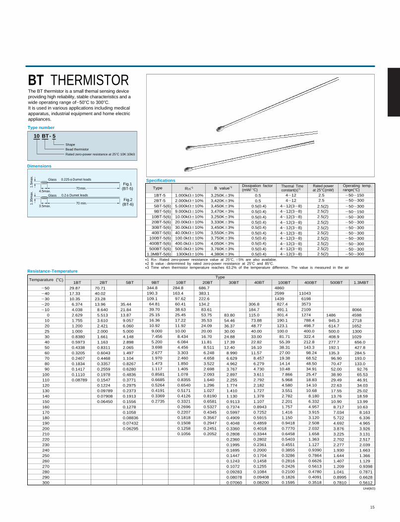
BT THERMISTORThe BT thermistor is a small themal sensing device providing high reliability, stable characteristics and a wide operating range of2508C to 3008C. It is used in various applications including medicalapparatus, industrial equipment and home electricappliances.
10 BT 5-
Bead thermistorShape
Rated zero-power resistance at 258C 10K:10kV
4.5max.
70 min.3.5max.
0.225 f Dumet leads
0.2f Dumet leadsFig.2
(BT-6)
Fig.1(BT-5)
Specifications
Type R25*1 B value*2 Dissipation factor(mW/ 8C)
Thermal Time constant(s)*3
Operating temp.range(8C)
Rated powerat 258C(mW)
*1 R25 : Rated zero-power resistance value at 258C, 65% are also availabie.
*2 B value : determined by rated zero-power resistance at 258C and 858C.
*3 Time when thermistor temperature reaches 63.2% of the temperature difference. The value is measured in the air
1BT-52BT-55BT-5(6)9BT-5(6)
10BT-5(6)20BT-5(6)30BT-5(6)40BT-5(6)
100BT-5(6)400BT-5(6)500BT-5(6)
1.3MBT-5(6)
1.000kV610%2.000kV610%5.000kV610%9.000kV610%10.00kV610%20.00kV610%30.00kV610%40.00kV610%100.0kV610%400.0kV610%500.0kV610%1300kV610%
3,250K63%3,420K63%3,450K63%3,470K63%3,250K63%3,330K63%3,450K63%3,550K63%3,750K63%4,050K63%3,760K63%4,380K63%
0.5(0.4)0.5(0.4)0.5(0.4)0.5(0.4)0.5(0.4)
0.5(0.4)0.5(0.4)0.5(0.4)0.5(0.4)0.5(0.4)
0.50.5
4;124;12
4;12(3;8)4;12(3;8)4;12(3;8)
4;12(3;8)4;12(3;8)4;12(3;8)4;12(3;8)4;12(3;8)4;12(3;8)4;12(3;8)
250;150
250;300
250;300
250;300250;300250;300250;300250;300250;300250;300250;300
250;150
2.52.5
2.5(2)2.5(2)2.5(2)
2.5(2)2.5(2)2.5(2)2.5(2)2.5(2)2.5(2)2.5(2)
Temparature (8C)Type
Resistance-Temperature
250240230220210
010202530405060708090
100110120130140150160170180190200210220230240250260270280290300
29.8717.3310.356.3744.0382.6291.7551.2001.0000.83800.59730.43380.32050.24070.18340.14170.11100.08789
70.7140.0223.2813.968.6405.5133.6102.4212.0001.6611.1630.83110.60430.4468
0.33570.25590.19780.15470.12240.097890.079080.06450
35.4421.8413.879.0576.0605.0004.1482.8982.0651.4971.1040.82670.62800.48360.37710.29750.23730.19130.15560.12780.10580.088360.074320.06295
344.8190.3109.164.8139.7025.1516.3610.929.0007.4565.2003.6982.6771.9701.4731.1170.85810.66850.52640.41910.33690.2735
284.8163.497.6260.4138.6325.4517.2211.9210.008.4346.0844.4563.3032.4601.8501.4051.0780.83550.65400.51710.41260.33210.26960.22070.18180.15080.12580.1056
686.7383.1222.6134.283.6153.7535.5324.0920.0016.7011.818.5116.2484.6583.5222.6982.0931.6401.2961.0270.81900.65810.53270.43450.35670.29470.24510.2052
83.8054.4636.3730.0024.8817.3912.408.9906.6294.9623.7672.8972.2551.7741.4101.1300.91130.73740.59970.49090.40480.33600.28080.23600.19950.16950.14470.12430.10720.092830.080780.07060
306.8184.7115.073.8848.7740.0033.0022.8216.1011.578.4576.2794.7303.6112.7922.1821.7271.3781.1070.89430.72520.59150.48590.40180.33440.28020.23610.20000.17040.14580.12550.10840.094080.08200
486025991439827.4491.1301.4190.1123.1100.081.7155.3938.3127.0019.3814.1410.487.8665.9684.5803.5512.7822.2011.7571.4161.1500.94180.77700.64580.54030.45510.38550.32860.28160.24260.21000.18260.1595
1486945.3614.7500.0408.9277.7192.1135.396.9070.4752.0038.9029.4922.6317.5513.7610.908.7177.0345.7224.6923.8763.2252.7022.2771.9301.6441.4071.2091.0410.89950.7810
806645982718165213001029
656.0427.8284.5193.0133.092.7665.5346.9134.0325.0218.5913.9910.638.163
6.3364.9653.9263.1312.5172.0391.6631.3661.1290.93980.78710.66280.5612
1BT 2BT 5BT 9BT 10BT 20BT 30BT 40BT 100BT 400BT 500BT 1.3MBT
110436198357321091274788.4498.7400.0322.4212.8143.398.2468.5248.5034.9125.4718.8314.1010.688.1806.3324.9573.9153.1202.5082.0321.6581.3631.1270.93900.78640.66260.56130.47800.40910.3518
Unit(kV)
16
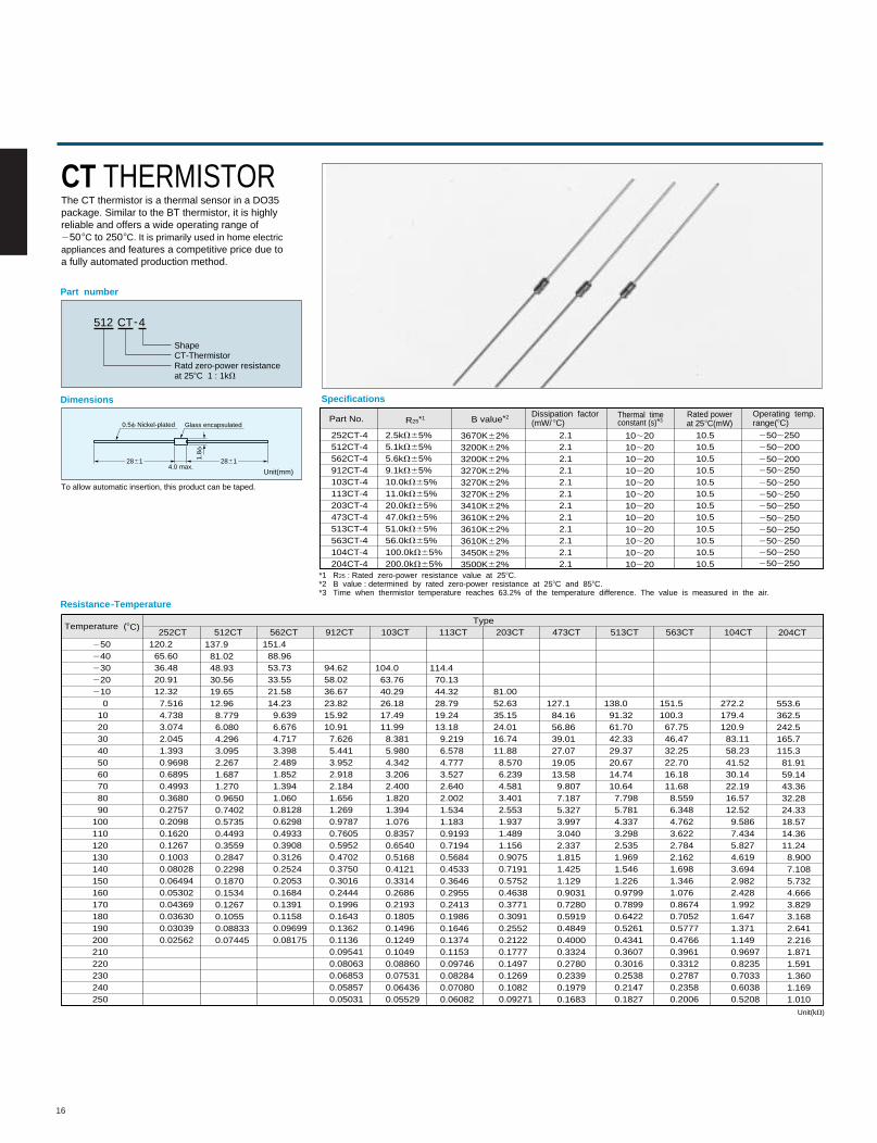
CT THERMISTORThe CT thermistor is a thermal sensor in a DO35package. Similar to the BT thermistor, it is highlyreliable and offers a wide operating range of 2508C to 2508C. It is primarily used in home electric appliances and features a competitive price due to a fully automated production method.
512 CT-4
ShapeCT-ThermistorRatd zero-power resistance at 258C 1 : 1kV
Part number
Dimensions
Resistance-Temperature
Glass encapsulated0.5f Nickel-plated
4.0 max.2861 28611.
8f
To allow automatic insertion, this product can be taped.
Temperature (8C)Type
252CT 512CT 562CT 912CT 103CT 113CT 203CT 473CT 513CT 563CT 104CT 204CT250240230220210
0102030405060708090
100110120130140150160170180190200210220230240250
120.265.6036.4820.9112.327.5164.7383.0742.0451.3930.96980.68950.49930.36800.27570.20980.16200.12670.10030.080280.064940.053020.043690.036300.030390.02562
137.981.0248.9330.5619.6512.968.7796.0804.2963.0952.2671.6871.2700.96500.74020.57350.44930.35590.28470.22980.18700.15340.12670.10550.088330.07445
151.488.9653.7333.5521.5814.239.6396.6764.7173.3982.4891.8521.3941.0600.81280.62980.49330.39080.31260.25240.20530.16840.13910.11580.096990.08175
94.6258.0236.6723.8215.9210.917.6265.4413.9522.9182.1841.6561.2690.97870.76050.59520.47020.37500.30160.24440.19960.16430.13620.11360.095410.080630.068530.058570.05031
104.063.7640.2926.1817.4911.998.3815.9804.3423.2062.4001.8201.3941.0760.83570.65400.51680.41210.33140.26860.21930.18050.14960.12490.10490.088600.075310.064360.05529
114.470.1344.3228.7919.2413.189.2196.5784.7773.5272.6402.0021.5341.1830.91930.71940.56840.45330.36460.29550.24130.19860.16460.13740.11530.097460.082840.070800.06082
81.0052.6335.1524.0116.7411.888.5706.2394.5813.4012.5531.9371.4891.1560.90750.71910.57520.46380.37710.30910.25520.21220.17770.14970.12690.10820.09271
127.184.1656.8639.0127.0719.0513.589.8077.1875.3273.9973.0402.3371.8151.4251.1290.90310.72800.59190.48490.40000.33240.27800.23390.19790.1683
138.091.3261.7042.3329.3720.6714.7410.647.7985.7814.3373.2982.5351.9691.5461.2260.97990.78990.64220.52610.43410.36070.30160.25380.21470.1827
151.5100.367.7546.4732.2522.7016.1811.688.5596.3484.7623.6222.7842.1621.6981.3461.0760.86740.70520.57770.47660.39610.33120.27870.23580.2006
272.2179.4120.983.1158.2341.5230.1422.1916.5712.529.5867.4345.8274.6193.6942.9822.4281.9921.6471.3711.1490.96970.82350.70330.60380.5208
553.6362.5242.5165.7115.381.9159.1443.3632.2824.3318.5714.3611.248.9007.1085.7324.6663.8293.1682.6412.2161.8711.5911.3601.1691.010
Specifications
Part No. R25*1 B value*2 Dissipation factor(mW/ 8C)
Thermal time constant (s)*3
Operating temp.range(8C)
Rated powerat 258C(mW)
*1 R25 : Rated zero-power resistance value at 258C.*2 B value : determined by rated zero-power resistance at 258C and 858C.*3 Time when thermistor temperature reaches 63.2% of the temperature difference. The value is measured in the air.
252CT-4512CT-4562CT-4912CT-4103CT-4113CT-4203CT-4473CT-4513CT-4563CT-4104CT-4204CT-4
2.5kV65%5.1kV65%5.6kV65%9.1kV65%10.0kV65%11.0kV65%20.0kV65%47.0kV65%51.0kV65%56.0kV65%100.0kV65%200.0kV65%
3670K62%3200K62%3200K62%3270K62%3270K62%3270K62%3410K62%3610K62%3610K62%3610K62%3450K62%3500K62%
2.12.12.12.12.12.12.12.12.12.12.12.1
10.510.510.510.510.510.510.510.510.510.510.510.5
10;2010;2010;2010;2010;2010;2010;2010;2010;2010;2010;2010;20
250;250250;200250;200250;250
250;250250;250250;250250;250250;250250;250250;250250;250
Unit(mm)
Unit(kV)
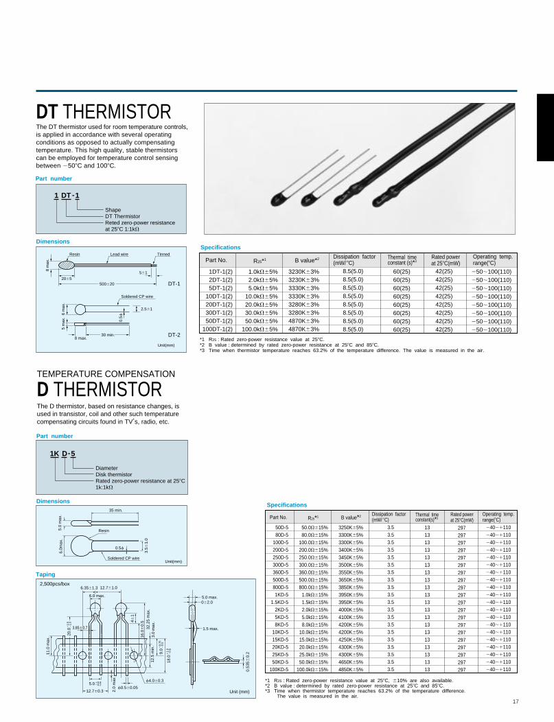
DT THERMISTORThe DT thermistor used for room temperature controls, is applied in accordance with several operating conditions as opposed to actually compensating temperature. This high quality, stable thermistors can be employed for temperature control sensingbetween 2508C and 1008C.
1 DT -1
ShapeDT ThermistorReted zero-power resistance at 258C 1:1kV
Part number
Dimensions
5006202065
2.561
561
8 m
ax.
6 m
ax.
5 m
ax.
8 max.30 min.
DT-1
DT-2
Resin Lead wire Tinned
Soldered CP wire
0.5f
Specifications
Part No. R25*1 B value*2 Dissipation factor(mW/ 8C)
Thermal time constant (s)*3
Operating temp.range(8C)
Rated powerat 258C(mW)
*1 R25 : Rated zero-power resistance value at 258C. *2 B value : determined by rated zero-power resistance at 258C and 858C.*3 Time when thermistor temperature reaches 63.2% of the temperature difference. The value is measured in the air.
1DT-1(2)2DT-1(2)5DT-1(2)
10DT-1(2)20DT-1(2)30DT-1(2)50DT-1(2)
100DT-1(2)
1.0kV65%2.0kV65%5.0kV65%
10.0kV65%20.0kV65%30.0kV65%50.0kV65%
100.0kV65%
3230K63%3230K63%3330K63%3330K63%3280K63%3280K63%4870K63%4870K63%
8.5(5.0)8.5(5.0)8.5(5.0)8.5(5.0)8.5(5.0)8.5(5.0)8.5(5.0)8.5(5.0)
60(25)60(25)60(25)60(25)60(25)60(25)60(25)60(25)
42(25)42(25)42(25)42(25)42(25)42(25)42(25)42(25)
250;100(110)250;100(110)250;100(110)250;100(110)250;100(110)250;100(110)250;100(110)250;100(110)
Unit(mm)
TEMPERATURE COMPENSATION
D THERMISTORThe D thermistor, based on resistance changes, isused in transistor, coil and other such temperaturecompensating circuits found in TV
,s, radio, etc.
1K D-5
DiameterDisk thermistorRated zero-power resistance at 258C1k:1kV
Part number
Dimensions
Taping
35 min.
5.0
max
.6.
0max
.
Resin
Soldered CP wire
3.56
1.0
0.5f
6.3561.3
062.0
6.0 max. 5.0 max.
1.5 max.
20.0
11.
52
1.0
9.0
10.
752
0.5
18.0
11.
02
0.5
5.010.820.2
3.8560.7
12.760.3
12.761.0
f0.560.05
11.0
max
.
2.0
max
32.2
5 m
ax.
3.0
max
.12
.5 m
in.
f4.060.3
461
16.0
60.
5
0.53
560.
2
2,500pcs/box
Unit (mm)
Unit(mm)
Specifications
Part No. R25*1 B value*2 Dissipation factor(mW/ 8C)
Thermal time constant(s)*3
Operating temp.range(8C)
Rated powerat 258C(mW)
*1 R25 : Rated zero-power resistance value at 258C, 610% are also available. *2 B value : determined by rated zero-power resistance at 258C and 858C.*3 Time when thermistor temperature reaches 63.2% of the temperature difference. The value is measured in the air.
50D-580D-5
100D-5200D-5250D-5300D-5360D-5500D-5800D-51KD-5
1.5KD-52KD-55KD-58KD-5
10KD-515KD-520KD-525KD-550KD-5
100KD-5
50.0V615%80.0V615%
100.0V615%200.0V615%250.0V615%300.0V615%360.0V615%500.0V615%800.0V615%
1.0kV615%1.5kV615%2.0kV615%5.0kV615%8.0kV615%
10.0kV615%15.0kV615%20.0kV615%25.0kV615%50.0kV615%
100.0kV615%
3250K65%3300K65%3300K65%3400K65%3450K65%3500K65%3550K65%3650K65%3850K65%3950K65%3950K65%4000K65%4100K65%4200K65%4200K65%4250K65%4300K65%4300K65%4650K65%4850K65%
3.53.53.53.53.53.53.53.53.53.53.53.53.53.53.53.53.53.53.53.5
1313131313131313131313131313131313131313
297297297297297297297297297297297297297297297297297297297297
240;1110240;1110240;1110240;1110240;1110240;1110240;1110240;1110240;1110240;1110240;1110240;1110240;1110240;1110240;1110240;1110240;1110240;1110240;1110240;1110
17
18
Dimensions
2927
27
33
Housing (Ta)
Housing (Ta)
Thermistor (Td)
Thermistor (Td)
Thermistor (Tc)
Thermistor (Tc)
Window
Window
Lead wire
Lead wire
f8.5Pipe
18
R4.35
1
5
(mm)
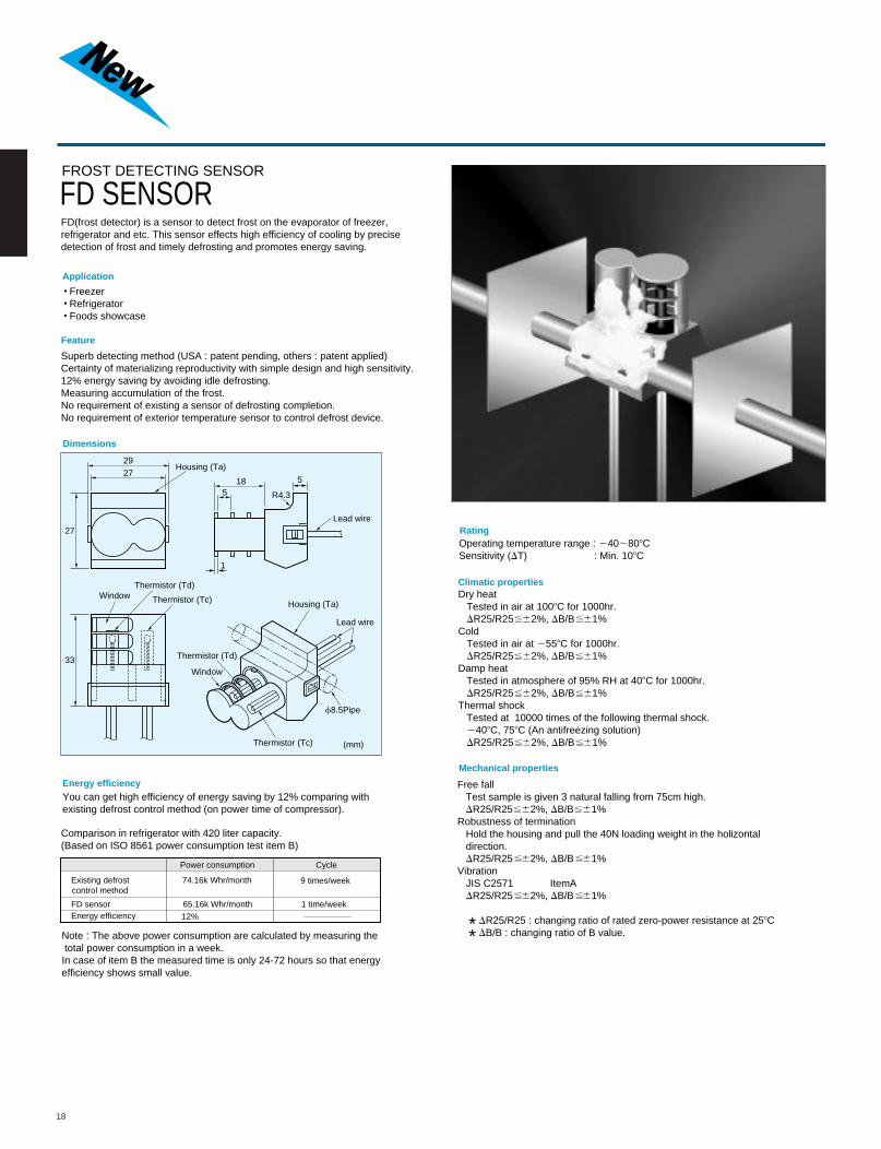
FROST DETECTING SENSOR
FD SENSORFD(frost detector) is a sensor to detect frost on the evaporator of freezer,refrigerator and etc. This sensor effects high efficiency of cooling by precisedetection of frost and timely defrosting and promotes energy saving.
Application
FreezerRefrigeratorFoods showcase
Feature
Superb detecting method (USA : patent pending, others : patent applied)Certainty of materializing reproductivity with simple design and high sensitivity.12% energy saving by avoiding idle defrosting.Measuring accumulation of the frost.No requirement of existing a sensor of defrosting completion.No requirement of exterior temperature sensor to control defrost device.
Energy efficiencyYou can get high efficiency of energy saving by 12% comparing with existing defrost control method (on power time of compressor).
Comparison in refrigerator with 420 liter capacity.(Based on ISO 8561 power consumption test item B)
Note : The above power consumption are calculated by measuring the total power consumption in a week.In case of item B the measured time is only 24-72 hours so that energyefficiency shows small value.
RatingOperating temperature range : 240;808CSensitivity (DT) : Min. 108C
Climatic propertiesDry heat Tested in air at 1008C for 1000hr. DR25/R25 62%, DB/B 61%Cold Tested in air at 2558C for 1000hr. DR25/R25 62%, DB/B 61%Damp heat Tested in atmosphere of 95% RH at 408C for 1000hr. DR25/R25 62%, DB/B 61%Thermal shock Tested at 10000 times of the following thermal shock. 2408C, 758C (An antifreezing solution) DR25/R25 62%, DB/B 61%
Mechanical properties
Free fall Test sample is given 3 natural falling from 75cm high. DR25/R25 62%, DB/B 61%Robustness of termination Hold the housing and pull the 40N loading weight in the holizontal direction. DR25/R25 62%, DB/B 61%Vibration JIS C2571 ItemA DR25/R25 62%, DB/B 61%
* DR25/R25 : changing ratio of rated zero-power resistance at 258C * DB/B : changing ratio of B value.
Power consumption Cycle
Existing defrostcontrol method
FD sensorEnergy efficiency
74.16k Whr/month
65.16k Whr/month
12%
9 times/week
1 time/week
.5.5
.5.5
.5.5
.5.5
.5.5
.5.5
.5.5
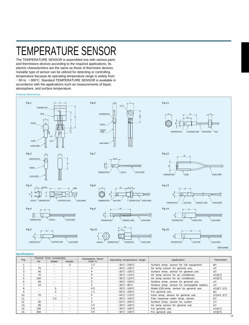
TEMPERATURE SENSORThe TEMPERATURE SENSOR is assembled one with various partsand thermistors devices according to the required applications. ltselectric characteristics are the same as those of thermistor devices.Variable type of sensor can be utilized for detecting or controllingtemperature because its operating temperature range is widely from250 to 13008C. Standard TEMPERATURE SENSOR is available inaccordance with the applications such as measurements of liquid, atmosphere, and surface temperature.
External dimensions
Fig 1
Fig 2
Fig 3
Fig 5
Fig 4
Fig 6
Fig 7
Fig 8
Fig 10
Fig 9
Fig 11
Fig 12
Fig 13
Fig 15
Fig 14
Unit (mm)
THERMISTOR
THERMISTOR
THERMISTOR
THERMISTORTHERMISTOR
THERMISTOR
TAPE
RESINRESIN
RESIN
TUBE
LEAD WIRE
LEAD WIRE
SHRINKTUBE
SHRINK TUBE
LEAD WIRE
LEAD WIRELEAD WIRE
LEAD WIRE
COPPER PLATE
EPOXY
THERMISTOR LEAD WIRECOPPER PIPE
f3
f3
f7
f6
f3.75
f2.4
5
5 6
12
25
517
15
23
EPOXY
3.5
5 5.5max. TUBE
13
25
f5
6.5m
ax.
13.3
5
1.9 7.1
25
25
40
SUS PIPE
THERMISTOR LEAD WIRERESIN PIPE
THERMISTOR LEAD WIRESUS PIPE
EPOXY LERD WIRE
2.5m
ax.
8max.
THERMISTOR
SHRINK TUBE LERD WIRE
f3.
5
30
16
7.8
THERMISTOR
LERD WIRETHERMISTORBRASS SCREW M5
LERD WIRESCREW PT1/8
f6
5012 10 5.5
THERMISTOR SUS PIPE
LERD WIRECOPPER CASE
23
13.3
14 7.5
30
THERMISTOR
TUBETHERMISTOR LERD WIRE
NUT
f6
14
f4
8
Specifications
FigThemal Time constant(s)
Air WaterDissipation factor
mW/ 8COperating temperature range Application Thermistor
123456789
101112131415
2
75 40 70130 65 10 2 2
702
30 85130260
2
2
2
2
2
2
2
5 3
2
Heater32
2
2
2
2
2
2
2
2
2
2
2
2
2
1.0 2 2 2 2
1.23454324.51.15131.52.62.6
2308C;2308C2308C;1058C2308C;1058C2308C;1108C2308C;1108C2308C;1058C2308C;908C2308C;1058C2508C;2008C2508C;1708C2308C;1008C2508C;2058C2308C;1008C2308C;1058C2308C;1058C
Surface temp. sensor for OA equipment.Air temp. sensor for general use.Surface temp. sensor for general use.Air temp. sensor for air conditioner.Air temp. sensor for air conditioner.Surface temp. sensor for general use.Surface temp. sensor for rechargeble battery.Water (Oil) temp. sensor for general use.For general use.Inner temp. sensor for general use.Fast response water temp. sensorSurface temp. sensor for cooker.Air temp. sensor for general use.For general use.For general use.
BTATATAT(ET)AT(ET)ATATAT(ET, GT)BTGT(AT, ET)ETCTETAT(ET)AT(ET)
19
20
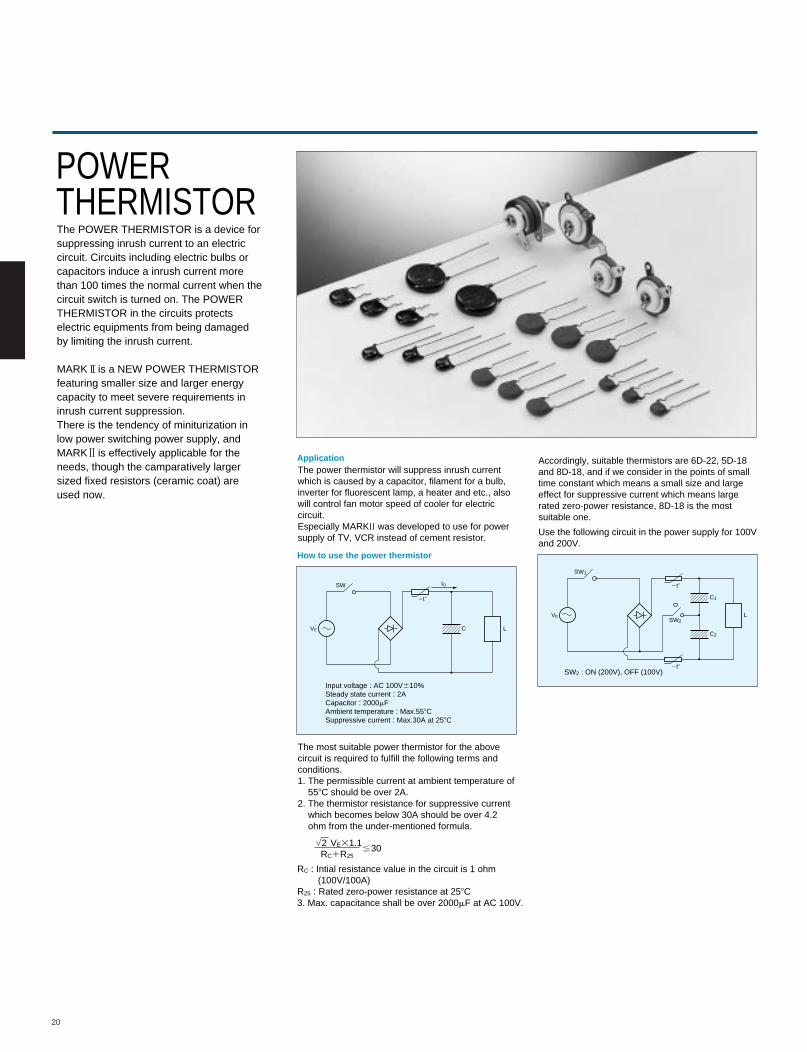
POWERTHERMISTORThe POWER THERMISTOR is a device forsuppressing inrush current to an electriccircuit. Circuits including electric bulbs orcapacitors induce a inrush current morethan 100 times the normal current when thecircuit switch is turned on. The POWERTHERMISTOR in the circuits protectselectric equipments from being damagedby limiting the inrush current.
MARK is a NEW POWER THERMISTORfeaturing smaller size and larger energycapacity to meet severe requirements ininrush current suppression.There is the tendency of miniturization inlow power switching power supply, andMARK is effectively applicable for theneeds, though the camparatively largersized fixed resistors (ceramic coat) areused now.
Application
How to use the power thermistor
The power thermistor will suppress inrush currentwhich is caused by a capacitor, filament for a bulb,inverter for fluorescent lamp, a heater and etc., alsowill control fan motor speed of cooler for electriccircuit.Especially MARK was developed to use for powersupply of TV, VCR instead of cement resistor.
Accordingly, suitable thermistors are 6D-22, 5D-18and 8D-18, and if we consider in the points of smalltime constant which means a small size and largeeffect for suppressive current which means largerated zero-power resistance, 8D-18 is the mostsuitable one.
Use the following circuit in the power supply for 100Vand 200V.
The most suitable power thermistor for the abovecircuit is required to fulfill the following terms andconditions.1. The permissible current at ambient temperature of 558C should be over 2A.2. The thermistor resistance for suppressive current which becomes below 30A should be over 4.2 ohm from the under-mentioned formula.
2t8
SW
VE
IO
C L
Input voltage : AC 100V610%Steady state current : 2ACapacitor : 2000mFAmbient temperature : Max.558CSuppressive current : Max.30A at 258C
SW1
SW2
C2
C1
VE L
2 VE31.1 30.5RC1R25
RC : Intial resistance value in the circuit is 1 ohm (100V/100A)R25 : Rated zero-power resistance at 258C3. Max. capacitance shall be over 2000mF at AC 100V.
SW2 : ON (200V), OFF (100V)
2t8
2t8
21
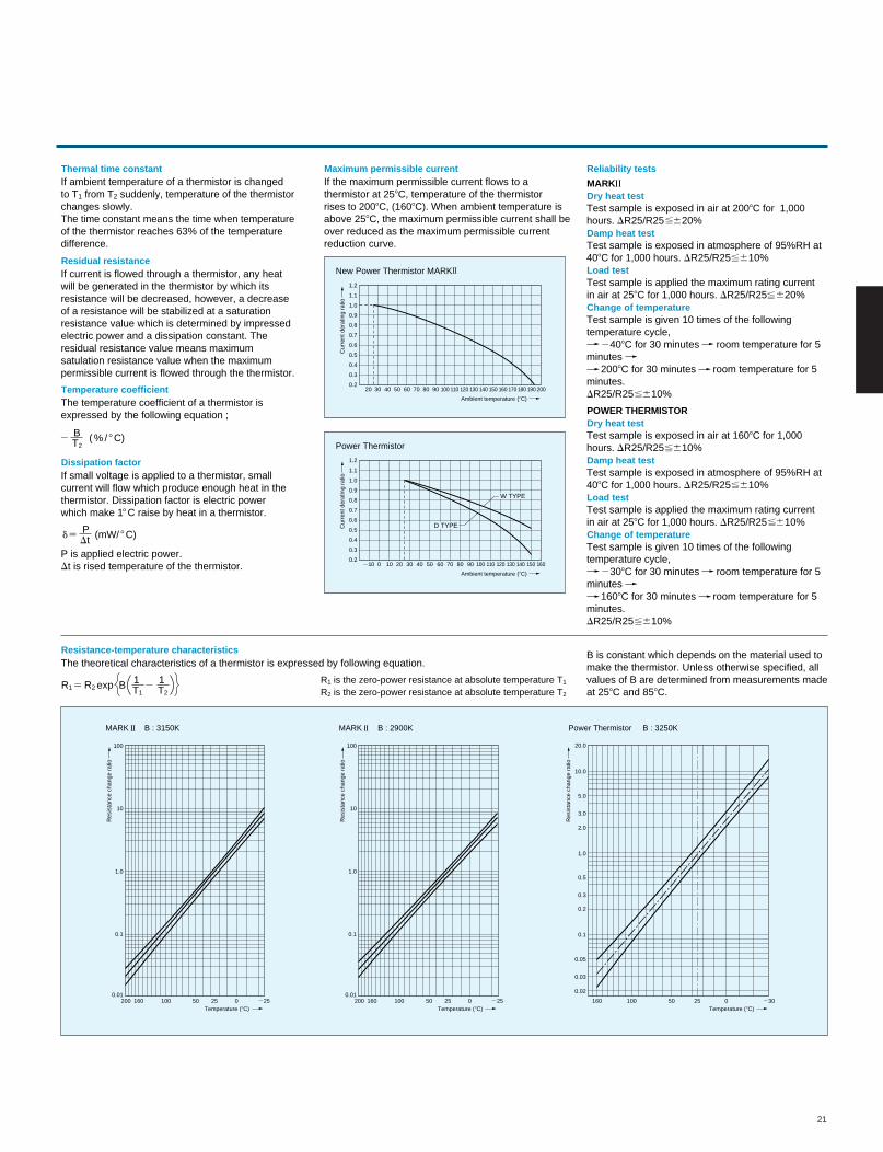
Thermal time constantIf ambient temperature of a thermistor is changedto T1 from T2 suddenly, temperature of the thermistorchanges slowly.The time constant means the time when temperatureof the thermistor reaches 63% of the temperaturedifference.
Maximum permissible currentIf the maximum permissible current flows to athermistor at 258C, temperature of the thermistorrises to 2008C, (1608C). When ambient temperature isabove 258C, the maximum permissible current shall beover reduced as the maximum permissible currentreduction curve.
Reliability tests
Dry heat testMARK
Test sample is exposed in air at 2008C for 1,000hours. DR25/R25 620%Damp heat testTest sample is exposed in atmosphere of 95%RH at408C for 1,000 hours. DR25/R25 610%Load testTest sample is applied the maximum rating currentin air at 258C for 1,000 hours. DR25/R25 620%Change of temperatureTest sample is given 10 times of the followingtemperature cycle, 2408C for 30 minutes room temperature for 5minutes 2008C for 30 minutes room temperature for 5minutes.DR25/R25 610%
Residual resistanceIf current is flowed through a thermistor, any heatwill be generated in the thermistor by which itsresistance will be decreased, however, a decreaseof a resistance will be stabilized at a saturationresistance value which is determined by impressedelectric power and a dissipation constant. Theresidual resistance value means maximumsatulation resistance value when the maximumpermissible current is flowed through the thermistor.
Temperature coefficientThe temperature coefficient of a thermistor isexpressed by the following equation ;
Dissipation factorIf small voltage is applied to a thermistor, smallcurrent will flow which produce enough heat in thethermistor. Dissipation factor is electric powerwhich make 18 C raise by heat in a thermistor.
Resistance-temperature characteristicsThe theoretical characteristics of a thermistor is expressed by following equation.
P is applied electric power.Dt is rised temperature of the thermistor.
New Power Thermistor MARK
1.2
1.1
1.0
0.9
0.8
0.7
0.6
0.5
0.4
0.3
0.220 30 40 50 60 70 80 90 100 110 120 130 140 150 160 170 180 190 200
Ambient temperature (8C)
Cur
rent
der
atin
g ra
tio
Power Thermistor
1.2
1.1
1.0
0.9
0.8
0.7
0.6
0.5
0.4
0.3
0.22010210 0 30 40 50 60 70 80 90 100 110 120 130 140 150 160
Ambient temperature (8C)
Temperature (8C)
Res
ista
nce
chan
ge r
atio
Cur
rent
der
atin
g ra
tio
D TYPE
W TYPE
2 ( % / 8 C)T2
B
25 exp B T1R1
R1 is the zero-power resistance at absolute temperature T1
R2 is the zero-power resistance at absolute temperature T2R2
1T2
1
5 (mW/ 8 C)dDtP
MARK B : 3150K
Dry heat testPOWER THERMISTOR
Test sample is exposed in air at 1608C for 1,000hours. DR25/R25 610%Damp heat testTest sample is exposed in atmosphere of 95%RH at408C for 1,000 hours. DR25/R25 610%Load testTest sample is applied the maximum rating currentin air at 258C for 1,000 hours. DR25/R25 610%Change of temperatureTest sample is given 10 times of the followingtemperature cycle, 2308C for 30 minutes room temperature for 5minutes 1608C for 30 minutes room temperature for 5minutes.DR25/R25 610%
B is constant which depends on the material used tomake the thermistor. Unless otherwise specified, allvalues of B are determined from measurements madeat 258C and 858C.
2000.01
0.1
1.0
10
100
160 100 50 25 2250Temperature (8C)
Res
ista
nce
chan
ge r
atio
MARK B : 2900K
2000.01
0.1
1.0
10
100
160 100 50 25 2250Temperature (8C)
Res
ista
nce
chan
ge r
atio
Power Thermistor B : 3250K
0.02
0.03
0.05
0.1
0.2
0.3
0.5
1.0
2.0
3.0
5.0
10.0
20.0
160 100 50 25 2300
.5
.5
.5
.5
.5
.5
.5
.5
22
Part number
Taping
Dimensions
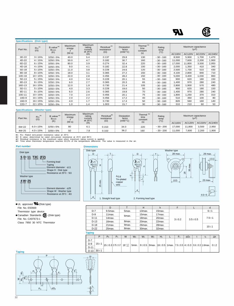
5 D 11 T3C (F2)-
Shape D : Disk typeElement diameter : f11
Resistance at 258C : 5V
Washer type
4 W 25-
Shape W : Washer typeElement diameter : f25
Resistance at 258C : 4V
D
F
hL
d
d
D T
H25
min
.
T
5D-11DU
f 0.8Tin-platedcopperwire
5D-11DU
1. Straight lead type 2. Forming lead type
W W0 W
1
W2
L
H1
P
P1
PO fD0
t1
t
Dh
F1
28 max. 29 max.
(11)
23 max.
f 335
18
35 m
ax.
(12)
Disk typeDisk type
Washer type
UL approved (Disk type)
File No. E92669
Thermistor type device
Canadian Standards (Disk type)
File No. CA97673-1
Class 7950 30 NTC Thermistor
R
Part No.R25
(V)B value
B25/85
(K)
Dissipation factor
(mW/ 8C)
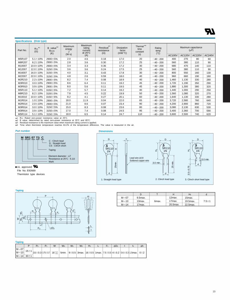
Specifications (Disk type)
Maximumenegy
J(W-s)
Maximumrating
currentat 258C
(A)
Residualresistance
(V)
Thermaltime
constant(s)
Ratingtemp(8C)
Maximum capacitance(mF)
3D-224D-226D-224D-185D-188D-18
10D-185D-138D-13
16D-135D-118D-11
10D-1110D-916D-922D-7
3615%4615%6615%4615%5615%8615%
10615%5615%8615%
16615%5615%8615%
10615%10615%16615%22615%
325065%325065%325065%
325065%325065%325065%325065%325065%325065%
325065%325065%325065%325065%325065%325065%325065%
40.050.080.09.0
11.018.022.04.06.0
12.04.06.07.02.04.01.0
5.44.73.94.13.83.12.83.42.71.93.32.62.42.21.71.4
0.1370.1820.2740.1820.2280.3650.4560.2280.3650.7300.2280.3650.4560.4560.7301.003
29.830.732.422.824.627.228.220.120.321.419.019.820.117.217.415.7
1301602201001201501505565
105507075405030
8,50011,00017,0002,0002,5004,1005,000
9001,4002,800
9001,4001,800
510820310
5,9007,600
11,8001,3501,7002,8003,400
620970
1,900620970
1,250350560210
1,4701,9002,950
34043071086015024048015024031080
14050
1,7002,2003,500
410510840
1,03018028057018028037010016060
AC100V AC120V AC220V AC240V
230;160230;160230;160
230;160230;160
230;160230;160
230;160
230;160230;160230;160230;160230;160230;160230;160230;160
Taping
D-7D-9D-11D-13
1561
3061
960.5 1660.5 7.560.5 460.3 0620.660.31560.3 3.7560.7 1811.0 20.5 3max. 1.6max.1max.5min.
P P0 P1 W W0 W1 W2 H1 L F1 fD0 t t1 Dh
D-7D-9D-11D-13D-18D-22
9.5max.11max.14max.16max.21max.25max.
8max.9max.8max.
13max.15max.18max.20max.26max.30max.
15max.17max.20max.22max.28max.32max.
360.2
661
3.560.57.561
1061
5max.
6max.
D T H h F L d
AC100V AC120V AC220V AC240V
Part No.R25
(V)B value
B25/85
(K)
Dissipation factor
(mW/ 8C)
Specifications (Washer type)
Maximumenegy
J(W-s)
Maximumrating
currentat 258C
(A)
Residualresistance
(V)
Thermaltime
constant(s)
Ratingtemp(8C)
Maximum capacitance(mF)
*4 Time when thermistor temperature reaches 63.2% of the temperature difference. The value is measured in the air.
6W-22
4W-25
6.0615% 325065%
325065%4.0615%
80
50
6.1
7.8
0.153
0.102
34.0
36.2
220
160
230;200
230;200
17,000 11,800 3,500 2,950
11,000 7,600 2,200 1,900
*1 *2 *3 *4
*1 R25 : Rated zero-power resistance value at 258C.
*2 B value : determined by rated zero-power resistance at 258C and 858C.
*3 Residual resistance is the maximum value when maximum rating current is applied.
Forming leadTaping
*1 *2 *3 *4
23
Part number
Taping
Dimensions
M 5R1 07 C
Element diameter : f7
Mark Resistance at 258C : 5.1V
1. Straight lead type
W W0 W
1
W2
L
H1
P
P1
PO fD0
t1
t
Dh
F1
UL approved
File No. E92669
Thermistor type devices
DD
25 m
in.
25m
in.
3.0 min.
dd
H0H5R110
1N5R1101N
D
3.0 min.
d
H0
5R1101N
T
3.56
0.75
Part No.R25
(V)B value
B25/85
(K)
Dissipation factor
(mW/ 8C)
Specifications (Disk type)
Maximumenegy
J(W.s)
Maximumrating
currentat 258C
(A)
Residualresistance
(V)
Thermaltime
constant(s)
Ratingtemp(8C)
Maximum capacitance(mF)
AC100V AC120V AC220V AC240V5.1610%8.2610%
10.0610%12.0610%16.0610%22.0610%2.2610%3.0610%3.9610%5.1610%8.2610%
10.0610%1.0610%2.0610%3.0610%3.9610%5.1610%
315065%315065%
315065%
4.63.63.33.63.12.67.46.45.65.74.54.1
11.98.68.37.46.5
0.180.300.360.240.430.590.080.110.110.140.220.270.040.070.080.080.14
17.017.217.217.517.818.018.919.219.519.219.920.122.023.423.624.524.7
290065%
315065%
315065%
290065%315065%
290065%
290065%290065%
290065%
315065%315065%
315065%290065%290065%
20253025304040454540506065908095
110
240;200
240;200240;200240;200240;200240;200240;200240;200240;200
240;200240;200240;200240;200240;200240;200240;200240;200
270380470380550660
1,1301,1901,3001,0001,0801,1302,5802,9002,1302,3602,500
80110140110160190330350380290320330760860630700740
6090
11090
130160280290320250270280640720530590620
M5R107M8R207M10007M12007M16007M22007M2R210M3R010M3R910M5R110M8R210M10010M1R014M2R014M3R014M3R914M5R114
2.02.83.43.64.04.88.28.68.07.27.88.2
18.021.015.017.018.0
400560680560800960
1,4601,7201,8801,4401,5601,6403,7204,2003,0803,4003,600
Taping
960.5 1660.5 7.560.5 460.2 0620.660.31560.3 3.7560.7 1811.0 20.5 3max. 1.5max.1max.5min.
P P0 P1 W W0 W1 W2 H1 L F1 fD0 t t1 Dh
D T H H0 dM...07M...10M...14
7.5619.5max.13max.17max.
12max.17max.20.5max.
15max.19.5max.22.5max.
6max.
1561
3061
M...07M...10M...14
*1 R25 : Rated zero-power resistance value at 258C.
*2 B value : determined by rated zero-power resistance at 258C and 858C.
*3
T3C : Clinch leadD : Straight leadCS : Clinch short
Taping
2. Clinch lead type 3. Clinch short lead type
Lead wire f0.8Soldered copper wire
Residual resistance is the maximum value when maximum rating current is applied.
*1 *2 *3 *4
*4 Time when thermistor temperature reaches 63.2% of the temperature difference. The value is measured in the air.
24
Fig 2
VC
VB
VS
IT'IL
ta
tb
IP
IP
VC
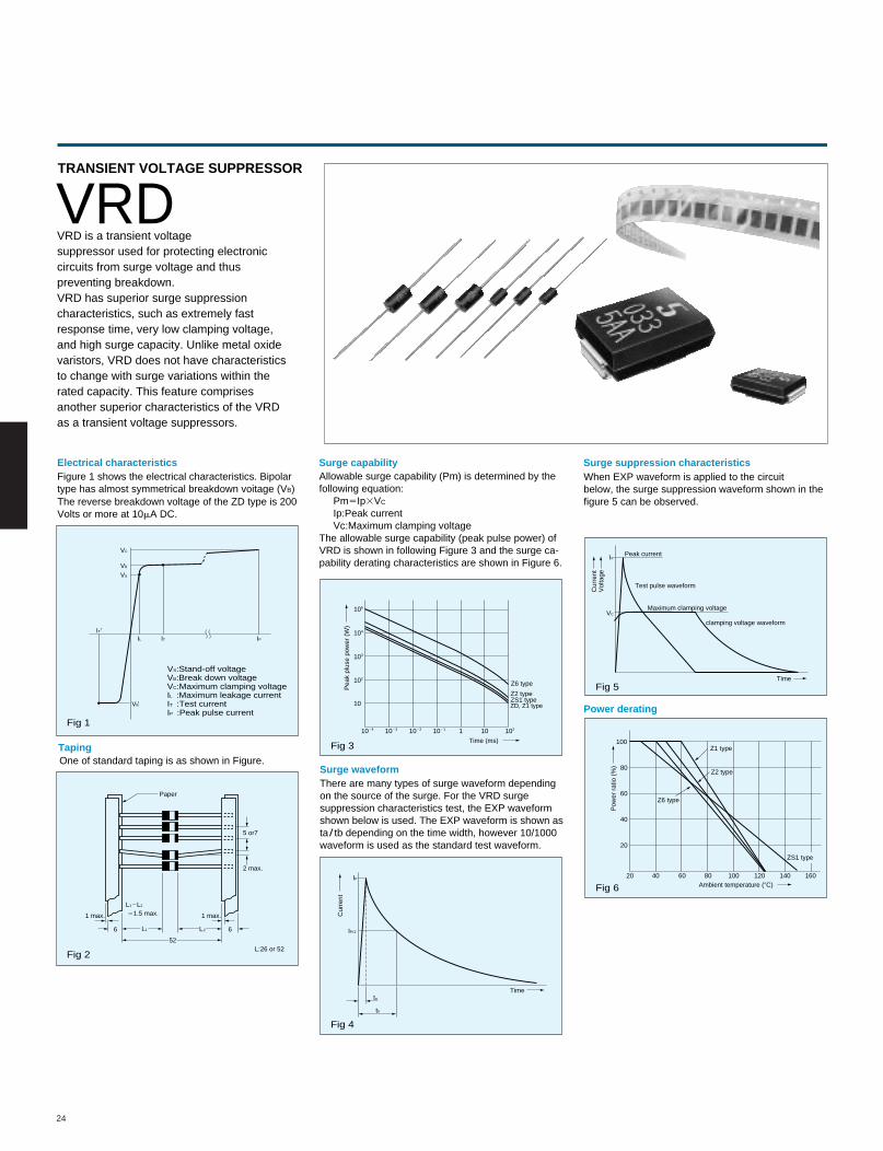
IP/2
VS:Stand-off voltageVB:Break down voltageVC:Maximum clamping voltageIL :Maximum leakage currentIT :Test currentIP :Peak pulse current
IT
L12L2
51.5 max.
Paper
IP
VB '
Fig 1
Fig 3
Fig 4
Fig 5
Fig 6
5 or7
2 max.
1 max.
6
1 max.
6
52L:26 or 52
105
104
1024 1023 1022 1021 102101
103
102
10
Time (ms)
Pea
k pl
use
pow
er (
W)
Ambient temperature (8C)
Pow
er r
atio
(%
)
Time
Cur
rent
Time
Peak current
Test pulse waveform
Maximum clamping voltageV
olta
geC
urre
nt
Z6 type
Z2 typeZS1 typeZD, Z1 type
clamping voltage waveform
100
80
60
40
20
20 40 60 80 100 120 140 160
TRANSIENT VOLTAGE SUPPRESSOR
VRDVRD is a transient voltagesuppressor used for protecting electroniccircuits from surge voltage and thuspreventing breakdown.VRD has superior surge suppressioncharacteristics, such as extremely fastresponse time, very low clamping voltage,and high surge capacity. Unlike metal oxidevaristors, VRD does not have characteristicsto change with surge variations within therated capacity. This feature comprisesanother superior characteristics of the VRDas a transient voltage suppressors.
Electrical characteristicsFigure 1 shows the electrical characteristics. Bipolartype has almost symmetrical breakdown voitage (VB)
Surge capabilityAllowable surge capability (Pm) is determined by thefollowing equation: Pm5Ip3VC
Ip:Peak current Vc:Maximum clamping voltageThe allowable surge capability (peak pulse power) ofVRD is shown in following Figure 3 and the surge ca-pability derating characteristics are shown in Figure 6.
Surge suppression characteristics
Power derating
When EXP waveform is applied to the circuitbelow, the surge suppression waveform shown in thefigure 5 can be observed.
Surge waveformThere are many types of surge waveform dependingon the source of the surge. For the VRD surgesuppression characteristics test, the EXP waveformshown below is used. The EXP waveform is shown asta/ tb depending on the time width, however 10/1000waveform is used as the standard test waveform.
The reverse breakdown voltage of the ZD type is 200Volts or more at 10mA DC.
TapingOne of standard taping is as shown in Figure.
L1 L2
Z1 type
Z2 type
Z6 type
ZS1 type
25
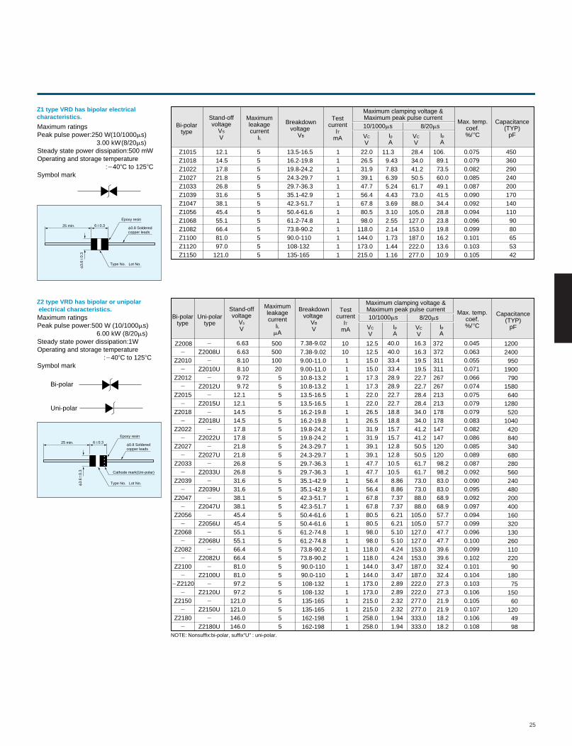
Z1 type VRD has bipolar electrical characteristics.
Maximum ratingsPeak pulse power:250 W(10/1000ms) 3.00 kW(8/20ms)Steady state power dissipation:500 mWOperating and storage temperature :2408C to 1258CSymbol mark
25 min. 660.3
f3.
660.
3
Epoxy resin
f0.8 Solderedcopper leads
Type No. Lot No.
Z2 type VRD has bipolar or unipolar electrical characteristics.Maximum ratingsPeak pulse power:500 W (10/1000ms) 6.00 kW (8/20ms)Steady state power dissipation:1WOperating and storage temperature :2408C to 1258CSymbol mark
25 min. 660.3
f3.
660.
3
Epoxy resin
f0.8 Solderedcopper leads
Type No. Lot No.
Bi-polartype
Stand-offvoltage
VS
V
Maximumleakagecurrent
IL
Breakdownvoltage
VB
Testcurrent
ITmA
Maximum clamping voltage &Maximum peak pulse current10/1000ms 8/20ms
Max. temp.coef.%/ 8CVC
VVC
VIpA
IpA
Capacitance(TYP)
pF
Z1015Z1018Z1022Z1027Z1033Z1039Z1047Z1056Z1068Z1082Z1100Z1120Z1150
12.114.517.821.826.831.638.145.455.166.481.097.0
121.0
5555555555555
13.5-16.516.2-19.819.8-24.224.3-29.729.7-36.335.1-42.942.3-51.750.4-61.661.2-74.873.8-90.290.0-110108-132135-165
1111111111111
22.026.531.939.147.756.467.880.598.0
118.0144.0173.0215.0
11.39.437.836.395.244.433.693.102.552.141.731.441.16
28.434.041.250.561.773.088.0
105.0127.0153.0187.0222.0277.0
106.89.173.560.049.141.534.428.823.819.816.213.610.9
0.0750.0790.0820.0850.0870.0900.0920.0940.0960.0990.1010.1030.105
4503602902402001701401109080655342
Bi-polartype
Uni-polartype
Stand-offvoltage
Vs
V
Maximumleakagecurrent
ILmA
Breakdownvoltage
VB
V
Testcurrent
ITmA
Maximum clamping voltage &Maximum peak pulse current10/1000ms 8/20ms
VC
VVC
VIpA
IpA
2
Z20102
Z20122
Z20152
Z20182
Z20222
Z20272
Z20332
Z20392
Z20472
Z20562
Z20682
Z20822
Z21002
2Z21202
Z21502
Z21802
Z2008U2
Z2010U2
Z2012U2
Z2015U2
Z2018U2
Z2022U2
Z2027U2
Z2033U2
Z2039U2
Z2047U2
Z2056U2
Z2068U2
Z2082U2
Z2100U2
Z2120U2
Z2150U2
Z2180U
6.638.10
8.109.729.72
12.112.114.514.517.817.821.821.826.826.831.631.638.138.145.445.455.155.166.466.481.081.097.297.2
121.0121.0146.0146.0
50010020555555555555555555555555555555
7.38-9.029.00-11.09.00-11.010.8-13.210.8-13.213.5-16.513.5-16.516.2-19.816.2-19.819.8-24.219.8-24.224.3-29.724.3-29.729.7-36.329.7-36.335.1-42.935.1-42.942.3-51.742.3-51.750.4-61.650.4-61.661.2-74.861.2-74.873.8-90.273.8-90.290.0-11090.0-110108-132108-132135-165135-165162-198162-198
1011111111111111111111111111111111
12.515.015.017.317.322.022.026.526.531.931.939.139.147.747.756.456.467.867.880.580.598.098.0
118.0118.0144.0144.0173.0173.0215.0215.0258.0258.0
40.033.433.428.928.922.722.718.818.815.715.712.812.810.510.58.868.867.377.376.216.215.105.104.244.243.473.472.892.892.322.321.941.94
16.319.519.522.722.728.428.434.034.041.241.250.550.561.761.773.073.088.088.0
105.0105.0127.0127.0153.0153.0187.0187.0222.0222.0277.0277.0333.0333.0
37231131126726721321317817814714712012098.298.283.083.068.968.957.757.747.747.739.639.632.432.427.327.321.921.918.218.2
NOTE: Nonsuffix:bi-polar, suffix"U" : uni-polar.
Cathode mark(Uni-polar)
Bi-polar
Uni-polar
Max. temp.coef.%/ 8C
Capacitance(TYP)
pF
Z2008 2 6.63 500 7.38-9.02 10 12.5 40.0 16.3 372 0.0450.0630.0550.0710.0660.0740.0750.0790.0790.0830.0820.0860.0850.0890.0870.0920.0900.0950.0920.0970.0940.0990.0960.1000.0990.1020.1010.1040.1030.1060.1050.1070.1060.108
12002400950
1900790
1580640
1280520
104042084034068028056024048020040016032013026011022090
18075
15060
1204998
26
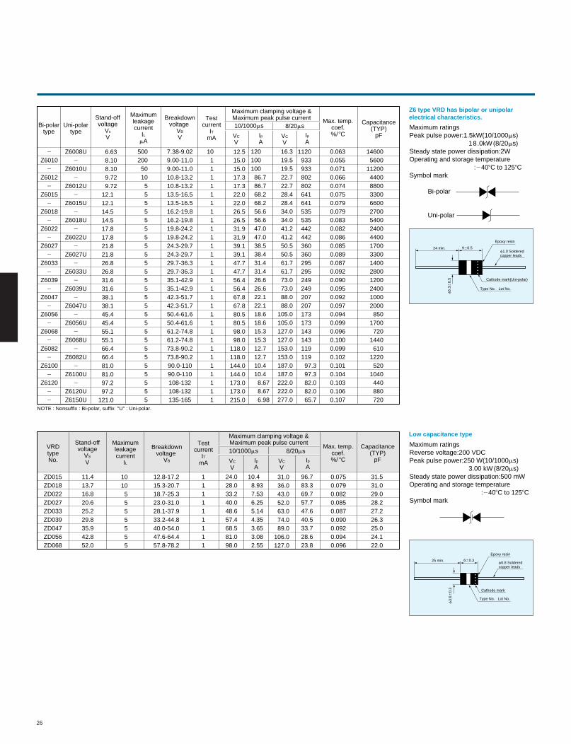
Maximum ratingsPeak pulse power:1.5kW(10/1000ms) 18.0kW(8/20ms)Steady state power dissipation:2WOperating and storage temperature :2408C to 1258CSymbol mark
24 min. 960.5
f5.
360.
5
Epoxy resin
f1.0 Solderedcopper leads
Type No. Lot No.
Low capacitance type
Z6 type VRD has bipolar or unipolar electrical characteristics.
Maximum ratingsReverse voltage:200 VDCPeak pulse power:250 W(10/1000ms) 3.00 kW (8/20ms)Steady state power dissipation:500 mWOperating and storage temperature :2408C to 1258CSymbol mark
25 min. 660.3
f3.
660.
3
Epoxy resin
f0.8 Solderedcopper leads
Type No. Lot No.
Cathode mark
Cathode mark(Uni-polar)
2
Z60102
Z60122
Z60152
Z60182
Z60222
Z60272
Z60332
Z60392
Z60472
Z60562
Z60682
Z60822
Z61002
Z61202
2
Z6008U2
Z6010U2
Z6012U2
Z6015U2
Z6018U2
Z6022U2
Z6027U2
Z6033U2
Z6039U2
Z6047U2
Z6056U2
Z6068U2
Z6082U2
Z6100U2
Z6120UZ6150U
16.319.519.522.722.728.428.434.034.041.241.250.550.561.761.773.073.088.088.0
105.0105.0127.0127.0153.0153.0187.0187.0222.0222.0277.0
112093393380280264164153553544244236036029529524924920720717317314314311911997.397.382.082.065.7
6.638.108.109.729.72
12.112.114.514.517.817.821.821.826.826.831.631.638.138.145.445.455.155.166.466.481.081.097.297.2
121.0
500200501055555555555555555555555555
7.38-9.029.00-11.09.00-11.010.8-13.210.8-13.213.5-16.513.5-16.516.2-19.816.2-19.819.8-24.219.8-24.224.3-29.724.3-29.729.7-36.329.7-36.335.1-42.935.1-42.942.3-51.742.3-51.750.4-61.650.4-61.661.2-74.861.2-74.873.8-90.273.8-90.290.0-11090.0-110108-132108-132135-165
1011111111111111111111111111111
12.515.015.017.317.322.022.026.526.531.931.939.139.147.747.756.456.467.867.880.580.598.098.0
118.0118.0144.0144.0173.0173.0215.0
12010010086.786.768.268.256.656.647.047.038.538.431.431.426.626.622.122.118.618.615.315.312.712.710.410.48.678.676.98
ZD015ZD018ZD022ZD027ZD033ZD039ZD047ZD056ZD068
12.8-17.215.3-20.718.7-25.323.0-31.028.1-37.933.2-44.840.0-54.047.6-64.457.8-78.2
11.413.716.820.625.229.835.942.852.0
10105555555
111111111
24.028.033.240.048.657.468.581.098.0
10.48.937.536.255.144.353.653.082.55
31.036.043.052.063.074.089.0
106.0127.0
96.783.369.757.747.640.533.728.623.8
0.0750.0790.0820.0850.0870.0900.0920.0940.096
Bi-polar
Uni-polar
Bi-polartype
Uni-polartype
Stand-offvoltage
Vs
V
Maximumleakagecurrent
ILmA
Breakdownvoltage
VB
V
Testcurrent
ITmA
Maximum clamping voltage &Maximum peak pulse current10/1000ms 8/20ms
VC
VVC
VIpA
IpA
NOTE : Nonsuffix : Bi-polar, suffix "U" : Uni-polar.
Max. temp.coef.%/ 8C
Capacitance(TYP)
pF
0.0630.0550.0710.0660.0740.0750.0790.0790.0830.0820.0860.0850.0890.0870.0920.0900.0950.0920.0970.0940.0990.0960.1000.0990.1020.1010.1040.1030.1060.107
146005600
112004400880033006600270054002400440017003300140028001200240010002000850
1700720
1440610
1220520
1040440880720
Stand-offvoltage
VS
V
Maximumleakagecurrent
IL
Breakdownvoltage
VB
Testcurrent
ITmA
Maximum clamping voltage &Maximum peak pulse current10/1000ms 8/20ms
Max. temp.coef.%/ 8CVC
VVC
VIpA
IpA
Capacitance(TYP)
pF
VRDtypeNo.
31.531.029.028.227.226.325.024.122.0
27
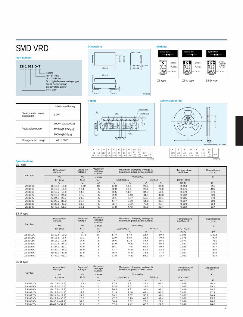
ZS 1 033 D-T
TapingNil : Bi-PolarU : Uni-PolarD : High-Reverse voltage typeBreak down voltageSteady state powerSMD type
Part number
Dimensions
Taping
Marking
4.360.2
4.760.3
1.260.2 1.260.2
0.2
2.060.3
0.1 max.
1.56
0.2
2.5 6
0.2
Symbol Mark
0125AA
S Mark
Part No.
Lot No.
fD0T1
A
B
fD1T2
P1
P1 P2 P0 T1 T2fD0 fD1EFWBA
3.0
60.1
5.2
60.1
12.0
60.3
5.5
60.05
1.75
60.1
4.0
60.1
2.0
60.1
4.0
60.1
1.510.120
1.510.220
0.3
60.05(2.6)
Unit (mm)
P2 P0
W
FE
Dimension of reel
W1A
f178
62.0
B
f80
61.0
C
f13
60.5
D
f21
60.8
E
2.0
60.5
W
14.0
61.5
r
(1.0)1.5
10.521.0
Unit (mm)
E
C
Dr
AW
Minimum quantity : 1500 / reel
W1
B
Steady state power dissipation
Peak pulse power
Storage temp. range
Maximum Rating
1.0W
300W(10/1000ms)
1200W(1.2/50ms)
2000W(8/20ms)
640;1508C
Part No.
Breakdownvoltage
Stand-offvoltage
Temperaturecoefficient
CapacitanceMaximumleakagecurrent
Maximum clamping voltage &Maximum peak pulse current
VB
It51mAV
VS
VS
D.C.
V
IL max
mA10/1000ms 8/20ms
VCmax/Ipp
V VA A pF
C258C;508C
%/ 8C
SpecificationsZS type
ZS1012ZS1015ZS1018ZS1022ZS1027ZS1033ZS1039ZS1047
12(10.8;13.2)15(13.5;16.5)18(16.2;19.8)22(19.8;24.2)27(24.3;29.7)33(29.7;36.3)39(35.1;42.9)47(42.3;51.7)
9.7212.114.517.821.826.831.638.1
105555555
17.322.026.531.939.147.756.467.8
17.313.611.39.407.676.295.324.42
22.428.534.441.450.761.873.188.0
89.370.258.148.339.432.427.422.7
0.0660.0750.0790.0820.0850.0870.0900.092
551465376299248198164137
Part No.
Breakdownvoltage
Stand-offvoltage
Temperaturecoefficient
Capacitance(TYP)
Maximumleakagecurrent
Maximum clamping voltage &Maximum peak pulse current
VB
It51mAV
VS
VS
D.C.
V
IL max
mA10/1000ms 8/20ms
VCmax/Ipp
V VA A pF
C258C;508C
%/ 8CZS1012DZS1015DZS1018DZS1022DZS1027DZS1033DZS1039DZS1047D
12(10.8;13.2)15(13.5;16.5)18(16.2;19.8)22(19.8;24.2)27(24.3;29.7)33(29.7;36.3)39(35.1;42.9)47(42.3;51.7)
9.7212.114.517.821.826.831.638.1
105555555
17.322.026.531.939.147.756.467.8
17.313.611.39.407.676.295.324.42
22.428.534.441.450.761.873.188.0
89.370.258.148.339.432.427.422.7
0.0660.0750.0790.0820.0850.0870.0900.092
30.229.128.227.326.425.524.824.0
ZS-D type
ZS-U type
Part No.
Breakdownvoltage
Stand-offvoltage
Temperaturecoefficient
CapacitanceMaximumleakagecurrent
Maximum clamping voltage &Maximum peak pulse current
VB
It51mAV
VS
VS
D.C.
V
IL max
mA10/1000ms 8/20ms
VCmax/Ipp
V VA A pF
C258C;508C
%/ 8CZS1012UZS1015UZS1018UZS1022UZS1027UZS1033UZS1039UZS1047U
12(10.8;13.2)15(13.5;16.5)18(16.2;19.8)22(19.8;24.2)27(24.3;29.7)33(29.7;36.3)39(35.1;42.9)47(42.3;51.7)
9.7212.114.517.821.826.831.638.1
105555555
17.322.026.531.939.147.756.467.8
17.313.611.39.407.676.295.324.42
22.428.534.441.450.761.873.188.0
89.370.258.148.339.432.427.422.7
0.0660.0750.0790.0820.0850.0870.0900.092
1,102929751598497395328274
SMD VRD
Unit(mm)
0125AA
S MarkCathode MarkPart No.
Lot No.
Symbol Mark
0125AA
S Mark
Part No.
Lot No.
Symbol Mark
ZS type ZS-U type ZS-D type
career tape
cover tape
(TYP)
(TYP)
28
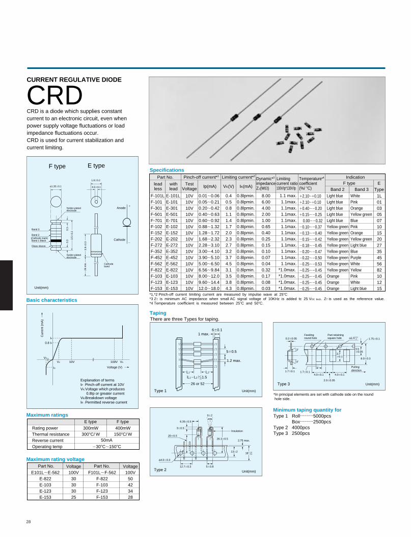
CURRENT REGULATIVE DIODE
CRDCRD is a diode which supplies constantcurrent to an electronic circuit, even when power supply voltage fluctuations or loadimpedance fluctuations occur.CRD is used for current stabilization andcurrent limiting.
1.860.2
0.560.1f1.3560.1
0.3
0.3
Solder-platedelectrode
Solder-platedelectrode
(Cathode mark) Band 1 Black
Band 3
Band 2
Glass sleeve
3.56
0.2
3.96
0.3
26 m
in.
Cathodeband
Anode
1
Cathode2
Unit(mm)
F type E type
100V
Voltage (V)
VB10VVK
VR
IR
IP
0.8 IP
Cur
rent
(m
A)
Explanation of termsIP :Pinch-off current at 10VVK:Voltage which produces 0.8Ip or greater currentVB:Breakdown voltageIR :Permitted reverse current
Basic characteristics
Taping
Specifications
There are three Types for taping.
Minimum taping quantity forType 1 Roll..........5000pcs Box..........2500pcsType 2 4000pcsType 3 2500pcs
Maximum ratings
Maximum rating voltage
Rating powerThermal resistanceReverse currentOperating temp
E101L;E-562E-822E-103E-123E-153
Voltage100V
30303025
E type
300mW3008C/ W
F type
400mW1508C/ W
2308C;1508C
50mA
F101L;F-562F-822F-103F-123F-153
Voltage100V
50423428
Type 1
Type 3
2060.5
062
360.5
6.3560.5
26.360.5
1362
560.812.760.3
f4.060.3
0.260.05
1.760.1 1.760.14.060.1 4.060.1
2.060.05
18
Insulation
2.75 max.
11.020.5
f1.510.120
Type 2
38
38
Pullingdirection
Part retainingsquare hole
Feedinground hole
8.060.3
1.7560.1
3.560.05
3.760.1
Unit(mm)
Unit(mm)
Unit(mm)
*In principal elements are set with cathode side on the round hole side.
560.5
660.1
1.2 max.
1 max.
L1
L12L2 ,1.5L2
26 or 52
*1,*2 Pinch-off current limiting current are measured by impulse wave at 258C*3 ZT is minimum AC impedance when small AC signal voltage of 10KHz is added tc 25 VDC biaS. ZT is used as the reference value.*4 Temperature coefficient is measured between 258C and 508C.
F-101LF-101F-301F-501F-701F-102F-152F-202F-272F-352F-452F-562F-822F-103F-123F-153
E-101LE-101E-301E-501E-701E-102E-152E-202E-272E-352E-452E-562E-822E-103E-123E-153
Light blueLight blueLight blueLight blueLight blueYellow greenYellow greenYellow greenYellow greenYellow greenYellow greenYellow greenYellow greenOrangeOrangeOrange
WhitePinkOrangeYellow greenBluePinkOrangeYellow greenLight blueBluePurpleWhiteYellowPinkWhiteLight blue
10V10V10V10V10V10V10V10V10V10V10V10V10V10V10V10V
1L010305071015202735455682101215
0.01;0.060.05;0.210.20;0.420.40;0.630.60;0.920.88;1.321.28;1.721.68;2.322.28;3.103.00;4.103.90;5.105.00;6.506.56;9.848.00;12.09.60;14.412.0;18.0
0.40.50.81.11.41.72.02.32.73.23.74.53.13.53.84.3
0.8lpmin.0.8lpmin.0.8lpmin.0.8lpmin.0.8lpmin.0.8lpmin.0.8lpmin.0.8lpmin.0.8lpmin.0.8lpmin.0.8lpmin.0.8lpmin.0.8lpmin.0.8lpmin.0.8lpmin.0.8lpmin.
8.006.004.002.001.000.650.400.250.150.100.070.040.320.170.080.03
1.1 max. 1.1max. 1.1max. 1.1max. 1.1max. 1.1max. 1.1max. 1.1max. 1.1max. 1.1max. 1.1max. 1.1max. *1.0max. *1.0max. *1.0max. *1.0max.
12.10;10.1012.10;10.1010.40;20.20 10.15;20.25 0.00;20.3220.10;20.37 20.13;20.40 20.15;20.4220.18;20.45 20.20;20.47 20.22;20.50 20.25;20.53 20.25;20.45 20.25;20.45 20.25;20.4520.25;20.45
Part No.
Part No. Part No.
IndicationF type
Band 2 Band 3E
Type
Pinch-off current*1 Limiting current*2Dynamic*3
impedanceZ1(MV)
Temperature*4
coefficient(%/ 8C)
Limitingcurrent ratio100V/Ip*130V/Ip
TestVoltage
withlead
leadless Ip(mA) VK(V) IK(mA)
22
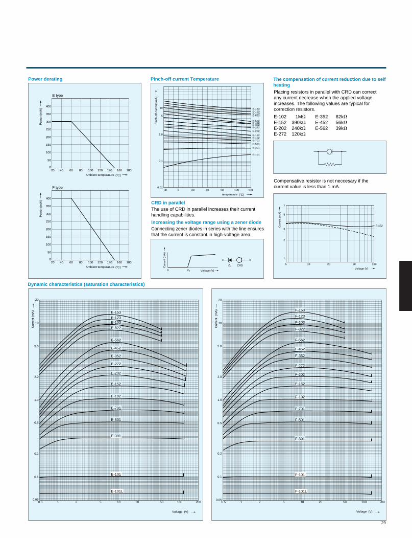
29
Power derating Pinch-off current Temperature
0.050.5 1 2 5 10 20 50 100 200
0.1
0.2
0.5
1.0
2.0
5.0
10
20
0.050.5 1 2 5 10 20 50 100 200
0.1
0.2
0.5
1.0
2.0
5.0
10
20
E-562
E-452
E-352
E-272
E-202
E-152
E-102
E-701
E-501
E-301
E-101
E-101L
E-153
E-123E-103
E-822
F-562
F-452
F-352
F-272
F-202
F-152
F-102
F-701
F-501
F-301
F-101
F-101L
F-153
F-123
F-103
F-822
400
350
300
250
200
150
100
50
0 20 40 60 80 100 120 140 160 180
Ambient temperature
Pow
er (
mW
)
E type
400
350
300
250
200
150
100
50
0 20 40 60 80 100 120 140 160 180
Ambient temperature
temperature
Pin
ch-o
ff cu
rren
t (m
A)
Pow
er (
mW
)
F type
CRD in parallelThe use of CRD in parallel increases their currenthandling capabilities.
The compensation of current reduction due to selfheatingPlacing resistors in parallel with CRD can correctany current decrease when the applied voltageincreases. The following values are typical forcorrection resistors.
Compensative resistor is not neccesary if thecurrent value is less than 1 mA.
E-102 1MVE-152 390kVE-202 240kVE-272 120kV
E-352 82kVE-452 56kVE-562 39kV
Increasing the voltage range using a zener diodeConnecting zener diodes in series with the line ensuresthat the current is constant in high-voltage area.
Dynamic characteristics (saturation characteristics)
0 Voltage (V)V2
ZDCur
rent
(m
A)
5
1
2
3
5
7
10 20 50 100
Voltage (V)
Cur
rent
(m
A)
CRD
10
5
1.0
0.1
0.01230 0 30 60 90 120 150
E-153
E-272
E-202
E-152E-102E-701
E-501
E-301
E-101
E-123E-103E-822
E-562E-452E-352
E-452
Cur
rent
(m
A)
Cur
rent
(m
A)
Voltage (V) Voltage (V)
(8C)
(8C)
(8C)
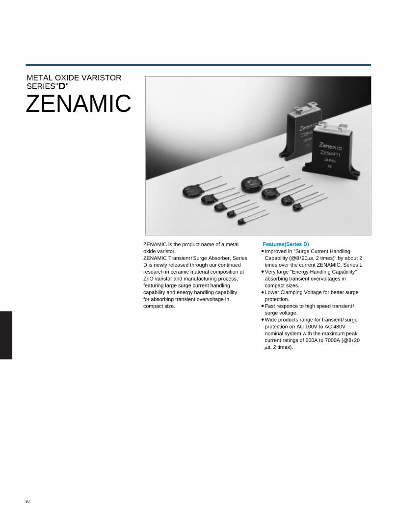
30
Features(Series D)
METAL OXIDE VARISTORSERIES"D"
ZENAMIC
ZENAMIC is the product name of a metaloxide varistor.ZENAMIC Transient / Surge Absorber, SeriesD is newly released through our continuedresearch in ceramic material composition ofZnO varistor and manufacturing process,featuring large surge current handlingcapability and energy handling capabilityfor absorbing transient overvoltage incompact size.
Improved in "Surge Current Handling Capability (@8/20ms, 2 times)" by about 2 times over the current ZENAMIC, Series L Very large "Energy Handling Capability" absorbing transient overvoltages in compact sizes. Lower Clamping Voltage for better surge protection. Fast responce to high speed transient/ surge voltage. Wide products range for transient/surge protection on AC 100V to AC 480V nominal system with the maximum peak current ratings of 600A to 7000A (@8/20 ms, 2 times).
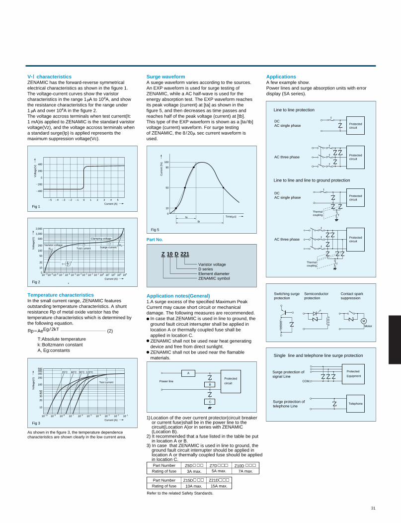
31
ZENAMIC has the forward-reverse symmetricalelectrical characteristics as shown in the figure 1.The voltage-current curves show the varistorcharacteristics in the range 1 mA to 104A, and showthe resistance characteristics for the range under 1 mA and over 104A in the figure 2.The voltage accross terminals when test current(It:1 mA)is applied to ZENAMIC is the standard varistorvoltage(Vz), and the voltage accross terminals whena standard surge(Ip) is applied represents themaximum suppression voltage(Vc).
Z 10 D 221
Varistor voltageD seriesElement diameterZENAMIC symbol
V- characteristicsA suege waveform varies according to the sources.An EXP waveform is used for surge testing ofZENAMIC, while a AC half-wave is used for theenergy absorption test. The EXP waveform reachesits peak voltage (current) at [ta] as shown in thefigure 5, and then decreases as time passes andreaches half of the peak voltage (current) at [tb].This type of the EXP waveform is shown as a [ta/ tb]voltage (current) waveform. For surge testingof ZENAMIC, the 8/20m sec current waveform isused.
Surge waveformA few example show.Power lines and surge absorption units with errordisplay (SA series).
Applications
In the small current range, ZENAMIC featuresoutstanding temperature characteristics. A shuntresistance Rp of metal oxide varistor has thetemperature characteristics which is determined bythe following equation.
Temperature characteristics1.A surge excess of the specified Maximum PeakCurrent may cause short circuit or mechanicaldamage. The following measures are recommended. In case that ZENAMIC is used in line to ground, the ground fault circuit interrupter shall be applied in location A or thermally coupled fuse shall be applied in location C. ZENAMIC shall not be used near heat generating device and free from direct sunlight. ZENAMIC shall not be used near the flamable materials.
1) Location of the over current protector(circuit breaker or current fuse)shall be in the power line to the circuit(Location A)or in series with ZENAMIC (Location B).2) It recommended that a fuse listed in the table be put in location A or B.3) In case that ZENAMIC is used in line to ground, the ground fault circuit interrupter should be applied in location A or thermally coupled fuse should be applied in location C.
Application notes(General)
Part No.
0
200
2200
2400
400
0 1 2 3 4 52122232425
Current (A)
Time(ms)
Cur
rent
(%
)
Vol
tage
(V)
Fig 1
Fig 5
5
10
20
50
200
500
100
2,000
1,000
21010 2910 2810 2710 2610 2510 2410 2310 2210 2110 010 110 210 310 410
Current (A)
Vol
tage
(V)
Fig 2
Clamping voltage
Varistor voltageRp
RsTest current Suege current
I5 CE a
10
20
504030
200
500400300
100
21010 2910 2810 2710 2610 2510 2410 2310 2210 2110
Current (A)
Vol
tage
(V)
Fig 3
100
90
50
10
0ta
tb
Rp5AeEg/2kT
T:Absolute temperaturek:Boltzmann constantA, Eg:constants
As shown in the figure 3, the temperature dependencecharacteristics are shown clearly in the low current area.
(2)
Test current
258C 608C 908C 1208C Protected
Equipment
COM.
Surge protection ofsignal Line
Surge protection oftelephone Line
Telephone
Protectedcircuit
Power line
A
B
C
Protected
circuit
Part Number
Rating of fuse 3A max. 5A max. 7A max.
Part Number
Rating of fuse
Refer to the related Safety Standards.
10A max. 15A max.
Line to line protection
Line to line and line to ground protection
Single line and telephone line surge protection
DCAC single phase
AC three phase Protectedcircuit
f
Protectedcircuit
DCAC single phase
Switching surgeprotection
Semiconductorprotection
Contact sparksuppression
f
f
f
f
f
AC three phase Protectedcircuit
f
f
f
f
Thermalcoupling
Thermalcoupling
M
Motor
Z5D Z7D Z10D
Z15D Z21D
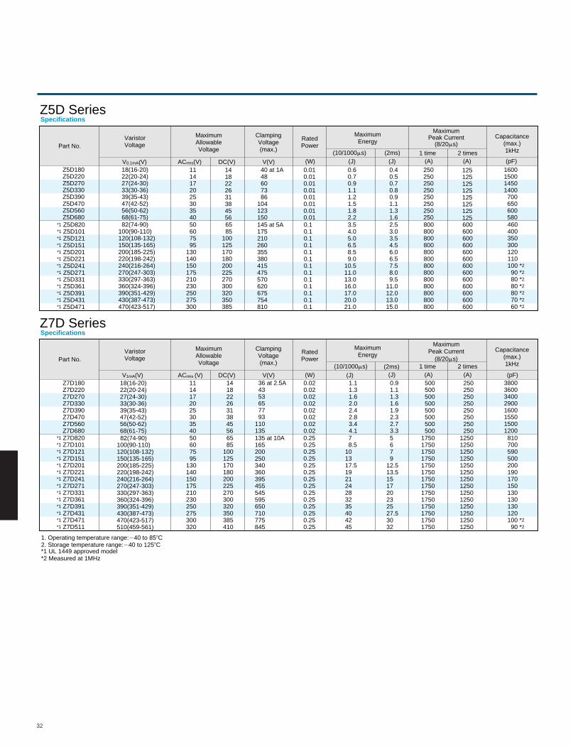
32
Z5D SeriesSpecifications
Part No.VaristorVoltage
V0.1mA(V)
MaximumAllowableVoltage
ACrms(V) DC(V)
ClampingVoltage(max.)
RatedPower
MaximumEnergy
MaximumPeak Current
(8/20ms)Capacitance
(max.)1kHz
V(V) (W) (J) (J) (A) (A) (pF)(10/1000ms) (2ms) 1 time 2 times
Z5D180Z5D220Z5D270Z5D330Z5D390Z5D470Z5D560Z5D680
*1 Z5D820*1 Z5D101*1 Z5D121*1 Z5D151*1 Z5D201*1 Z5D221*1 Z5D241*1 Z5D271*1 Z5D331*1 Z5D361*1 Z5D391*1 Z5D431*1 Z5D471
18(16-20)22(20-24)27(24-30)33(30-36)39(35-43)47(42-52)56(50-62)68(61-75)
82(74-90)100(90-110)120(108-132)150(135-165)200(185-225)220(198-242)240(216-264)270(247-303)330(297-363)360(324-396)390(351-429)430(387-473)470(423-517)
111417202530354050607595
130140150175210230250275300
14182226313845566585
100125170180200225270300320350385
40 at 1A 48 60 73 86104123150145 at 5A175210260355380415475570620675754810
0.010.010.010.010.010.010.010.010.10.10.10.10.10.10.10.10.10.10.10.10.1
0.60.70.91.11.21.51.82.23.54.05.06.58.59.0
10.511.013.016.017.020.021.0
0.40.50.70.80.91.11.31.62.53.03.54.56.06.57.58.09.5
11.012.013.015.0
250250250250250250250250800800800800800800800800800800800800800
125125125125125125125125600600600600600600600600600600600600600
1600150014501400700650600580460400350300120110100 *2
90 *2
80 *2
80 *2
80 *2
70 *2
60 *2
Z7D SeriesSpecifications
Part No.VaristorVoltage
V1mA(V)
MaximumAllowableVoltage
ACrms (V) DC(V)
ClampingVoltage(max.)
RatedPower
MaximumEnergy
MaximumPeak Current
(8/20ms)
Capacitance(max.)1kHz
V(V) (W) (J) (J) (A) (A) (pF)(10/1000ms) (2ms) 1 time 2 times
Z7D180Z7D220Z7D270Z7D330Z7D390Z7D470Z7D560Z7D680
18(16-20)22(20-24)27(24-30)33(30-36)39(35-43)47(42-52)56(50-62)68(61-75)
1114172025303540
1418222631384556
36 at 2.5A 43 53 65 77 93110135
0.020.020.020.020.020.020.020.02
1.11.31.62.02.42.83.44.1
0.91.11.31.61.92.32.73.3
500500500500500500500500
250250250250250250250250
38003600340029001600155015001200
*1 Z7D820*1 Z7D101*1 Z7D121*1 Z7D151*1 Z7D201*1 Z7D221*1 Z7D241*1 Z7D271*1 Z7D331*1 Z7D361*1 Z7D391*1 Z7D431*1 Z7D471*1 Z7D511
82(74-90)100(90-110)120(108-132)150(135-165)200(185-225)220(198-242)240(216-264)270(247-303)330(297-363)360(324-396)390(351-429)430(387-473)470(423-517)510(459-561)
50607595
130140150175210230250275300320
6585
100125170180200225270300320350385410
135 at 10A165200250340360395455545595650710775845
0.250.250.250.250.250.250.250.250.250.250.250.250.250.25
7 8.5101317.5192124283235404245
5 6 7 912.513.5151720232527.53032
810700590500200190170 150 130 130 130 120 100 *2
90 *2
17501750175017501750175017501750175017501750175017501750
12501250125012501250125012501250125012501250125012501250
1. Operating temperature range:240 to 858C2. Storage temperature range:240 to 1258C*1 UL 1449 approved model*2 Measured at 1MHz
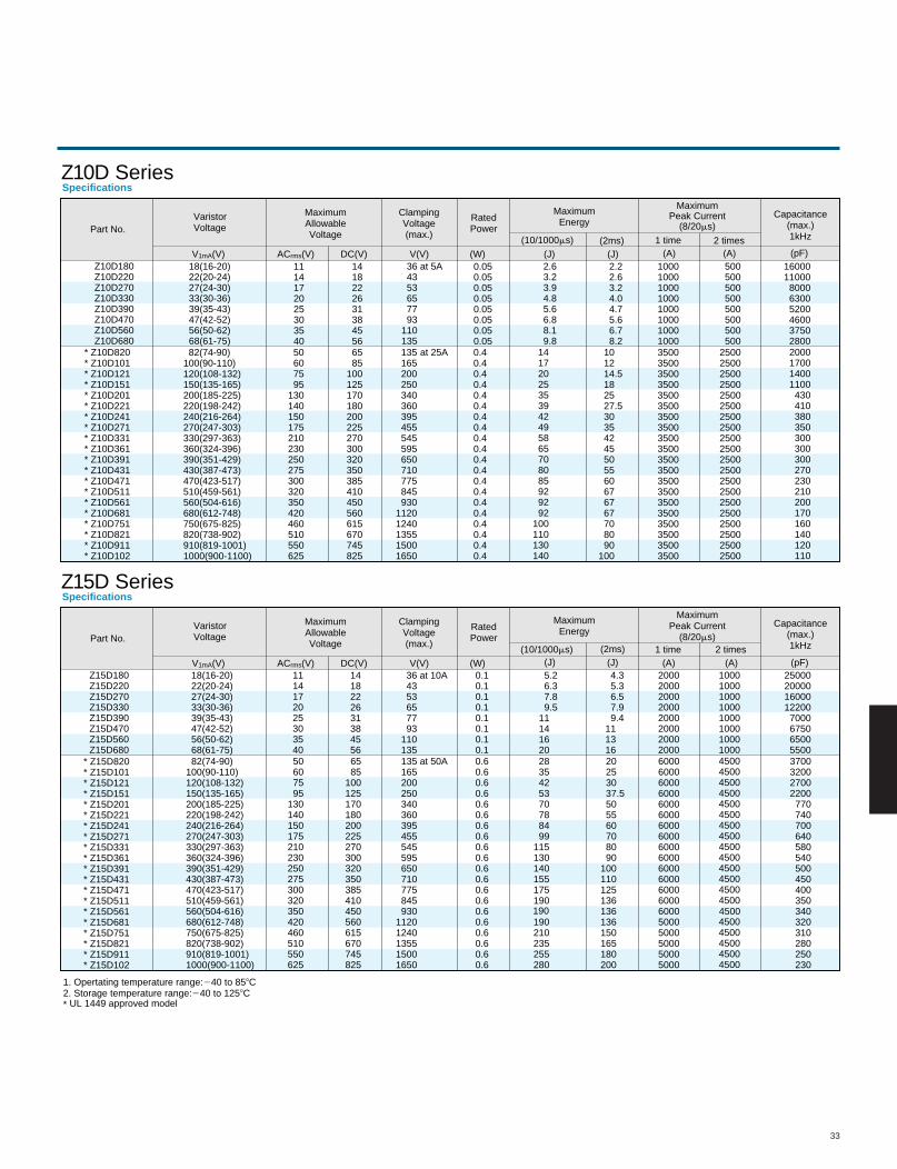
33
Z10D SeriesSpecifications
Part No.VaristorVoltage
V1mA(V)
MaximumAllowableVoltage
ACrms(V) DC(V)
ClampingVoltage(max.)
RatedPower
MaximumEnergy
MaximumPeak Current
(8/20ms)Capacitance
(max.)1kHz
V(V) (W) (J) (J) (A) (A) (pF)(10/1000ms) (2ms) 1 time 2 times
1. Opertating temperature range:240 to 858C2. Storage temperature range:240 to 1258C* UL 1449 approved model
Z10D180Z10D220Z10D270Z10D330Z10D390Z10D470Z10D560Z10D680
18(16-20)22(20-24)27(24-30)33(30-36)39(35-43)47(42-52)56(50-62)68(61-75)
1114172025303540
1418222631384556
36 at 5A 43 53 65 77 93110135
0.050.050.050.050.050.050.050.05
2.63.23.94.85.66.88.19.8
2.22.63.24.04.75.66.78.2
10001000100010001000100010001000
500500500500500500500500
1600011000800063005200460037502800
* Z10D820* Z10D101* Z10D121* Z10D151* Z10D201* Z10D221* Z10D241* Z10D271* Z10D331* Z10D361* Z10D391* Z10D431* Z10D471* Z10D511* Z10D561* Z10D681* Z10D751* Z10D821* Z10D911* Z10D102
82(74-90)100(90-110)120(108-132)150(135-165)200(185-225)220(198-242)240(216-264)270(247-303)330(297-363)360(324-396)390(351-429)430(387-473)470(423-517)510(459-561)560(504-616)680(612-748)750(675-825)820(738-902)910(819-1001)1000(900-1100)
50607595
130140150175210230250275300320350420460510550625
6585
100125170180200225270300320350385410450560615670745825
0.40.40.40.40.40.40.40.40.40.40.40.40.40.40.40.40.40.40.40.4
14172025353942495865708085929292
100110130140
101214.5182527.530354245505560676767708090
100
35003500350035003500350035003500350035003500350035003500350035003500350035003500
25002500250025002500250025002500250025002500250025002500250025002500250025002500
2000170014001100430410380350300300300270230210200170160140120110
Z15D SeriesSpecifications
Part No.VaristorVoltage
V1mA(V)
MaximumAllowableVoltage
ACrms(V) DC(V)
ClampingVoltage(max.)
RatedPower
MaximumEnergy
MaximumPeak Current
(8/20ms)Capacitance
(max.)1kHz
V(V) (W) (J) (J) (A) (A) (pF)(10/1000ms) (2ms) 1 time 2 times
Z15D180Z15D220Z15D270Z15D330Z15D390Z15D470Z15D560Z15D680
18(16-20)22(20-24)27(24-30)33(30-36)39(35-43)47(42-52)56(50-62)68(61-75)
1114172025303540
1418222631384556
36 at 10A 43 53 65 77 93110135
0.10.10.10.10.10.10.10.1
5.2 6.3 7.8 9.511141620
4.3 5.3 6.5 7.9 9.4111316
20002000200020002000200020002000
10001000100010001000100010001000
250002000016000122007000675065005500
* Z15D820 * Z15D101 * Z15D121 * Z15D151 * Z15D201 * Z15D221 * Z15D241 * Z15D271 * Z15D331 * Z15D361 * Z15D391 * Z15D431 * Z15D471 * Z15D511 * Z15D561 * Z15D681 * Z15D751 * Z15D821 * Z15D911 * Z15D102
82(74-90)100(90-110)120(108-132)150(135-165)200(185-225)220(198-242)240(216-264)270(247-303)330(297-363)360(324-396)390(351-429)430(387-473)470(423-517)510(459-561)560(504-616)680(612-748)750(675-825)820(738-902)910(819-1001)1000(900-1100)
50 60 75 95130140150175210230250275300320350420460510550625
65 85100125170180200225270300320350385410450560615670745825
135 at 50A 165 200 250 340 360 395 455 545 595 650 710 775 845 93011201240135515001650
0.60.60.60.60.60.60.60.60.60.60.60.60.60.60.60.60.60.60.60.6
2835425370788499
115130140155175190
190210235255280
20 25 30 37.5 50 55 60 70 80 90100110125136136136150165180200
60006000600060006000600060006000600060006000600060006000600050005000500050005000
45004500450045004500450045004500450045004500450045004500
45004500450045004500
3700320027002200770740700640580540500450400350340320310280250230
135165200250340360395455545595650710775845930
11201240135515001650
at 25A
190 4500
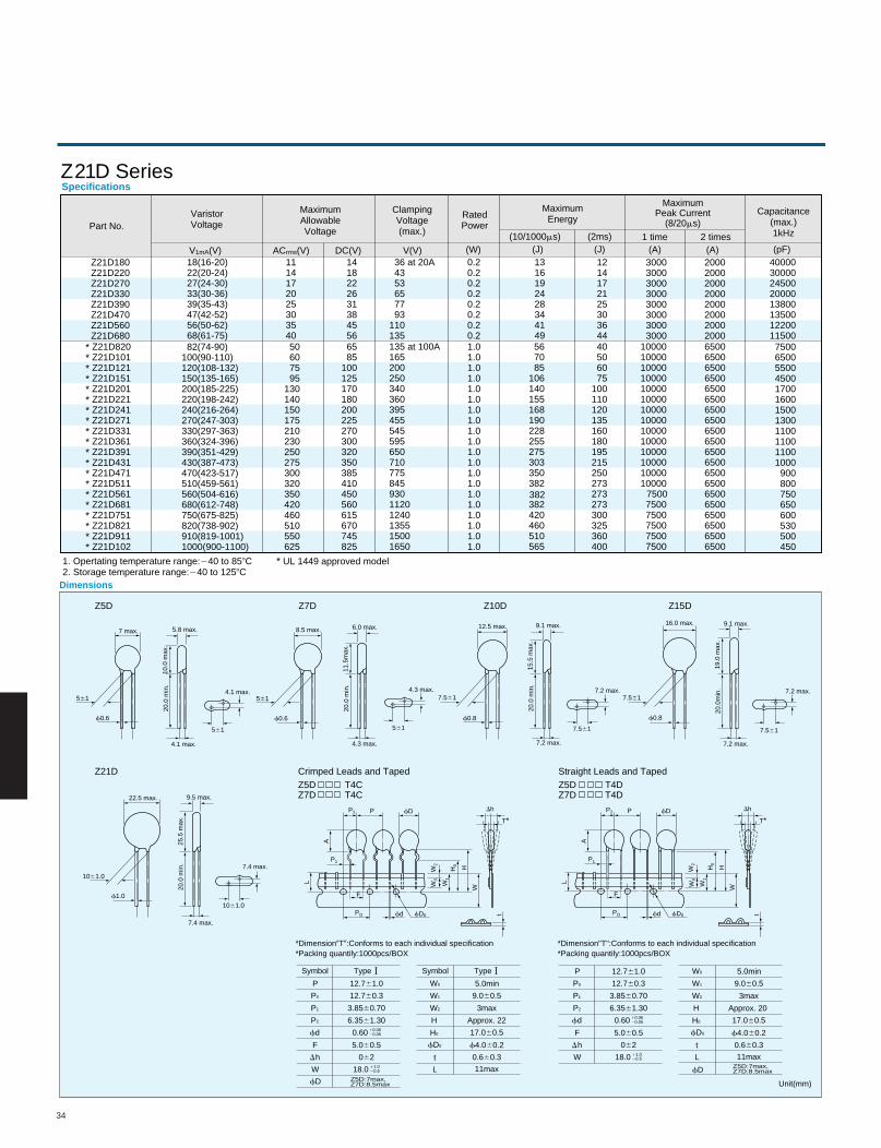
34
Dimensions
12.5 max. 16.0 max.9.1 max. 9.1 max.5.8 max. 6.0 max.
7 max. 8.5 max.
22.5 max. 9.5 max.
15.5
max
.
19.0
max
.
10.0
max
.
11.5
max
.
25.5
max
.
20.0
min
.
20.0
min
.
20.0
min
.
20.0
min
.
20.0
min
.
7.561 7.561561 561
1061.0
1061.0
7.561 7.561561 561
f0.8 f0.8f0.6 f0.6
f1.0
7.2 max. 7.2 max.4.1 max. 4.3 max.
7.4 max.
7.2 max. 7.2 max.4.1 max. 4.3 max.
7.4 max.
P2 P fD
A
P1
L
F
PO fD0fd
W0
W1
W2
H0
H
W
t
Dh
T*P2 P fD
A
P1
L
F
PO fD0fd
W0
W1
W2
H0 H
W
t
Dh
T*
Z5D
Z21D Crimped Leads and Taped
Z7D Z10D Z15D
Z5D T4CZ7D T4C
Straight Leads and TapedZ5D T4DZ7D T4D
*Dimension0T0:Conforms to each individual specification*Packing quantily:1000pcs/BOX
Symbol
P
F
W
h
fd
fD Z5D:7max,Z7D:8.5max
fD Z5D:7max,Z7D:8.5max
P0
P1
P2
Type
12.761.0
5.060.5
18.0
062
0.60
12.760.3
3.8560.70
6.3561.3010.0620.05
11.020.5
Symbol
t
L
W1
W0
W2
H0
H
Type
5.0min
f4.060.2
17.060.5
0.660.3
9.060.5
3max
11max
Approx. 22
5.0min
f4.060.2
17.060.5
0.660.3
9.060.5
3max
11max
Approx. 20
*Dimension"T":Conforms to each individual specification*Packing quantily:1000pcs/BOX
P
F
W
h
fd
P0
P1
P2
12.761.0
5.060.5
18.0
062
0.60
12.760.3
3.8560.70
6.3561.3010.0620.05
11.020.5
t
L
fD0
fD0
W1
W0
W2
H0
H
Unit(mm)
Z21D SeriesSpecifications
Part No.VaristorVoltage
V1mA(V)
MaximumAllowableVoltage
ACrms(V) DC(V)
ClampingVoltage(max.)
RatedPower
MaximumEnergy
MaximumPeak Current
(8/20ms)Capacitance
(max.)1kHz
V(V) (W) (J) (J) (A) (A) (pF)(10/1000ms) (2ms) 1 time 2 times
1. Opertating temperature range:240 to 858C2. Storage temperature range:240 to 1258C
Z21D180Z21D220Z21D270Z21D330Z21D390Z21D470Z21D560Z21D680
18(16-20)22(20-24)27(24-30)33(30-36)39(35-43)47(42-52)56(50-62)68(61-75)
1114172025303540
1418222631384556
36 at 20A 43 53 65 77 93110135
0.20.20.20.20.20.20.20.2
1316192428344149
1214172125303644
30003000300030003000300030003000
20002000200020002000200020002000
4000030000245002000013800135001220011500
* Z21D820* Z21D101* Z21D121* Z21D151* Z21D201* Z21D221* Z21D241* Z21D271* Z21D331* Z21D361* Z21D391* Z21D431* Z21D471* Z21D511* Z21D561* Z21D681* Z21D751* Z21D821* Z21D911* Z21D102
82(74-90)100(90-110)120(108-132)150(135-165)200(185-225)220(198-242)240(216-264)270(247-303)330(297-363)360(324-396)390(351-429)430(387-473)470(423-517)510(459-561)560(504-616)680(612-748)750(675-825)820(738-902)910(819-1001)1000(900-1100)
50 60 75 95130140150175210230250275300320350420460510550625
65 85100125170180200225270300320350385410450560615670745825
135 at 100A16520025034036039545554559565071077584593011201240135515001650
1.01.01.01.01.01.01.01.01.01.01.01.01.01.01.01.01.01.01.01.0
567085
106140155168190228255275303350382
382420460510565
40506075
100110120135160180195215250273273273300325360400
1000010000100001000010000100001000010000100001000010000100001000010000
75007500750075007500
65006500650065006500650065006500650065006500650065006500650065006500650065006500
750065005500450017001600150013001100110011001000900800750650600530500450
* UL 1449 approved model
382 7500
D
D
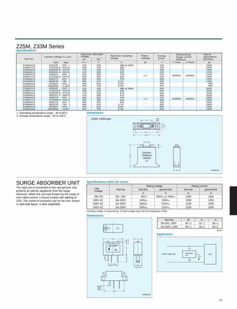
35
Dimensions
Dimensions
Application
Z25M, Z33M type
The said unit is connected to line and ground, andprotects an electric appliance from the surgeinfluence. When the unit was broken by the surge ofover rated current, it shows trouble with lighting ofLED. The socket of exclusive use for the unit, shownin right side figure, is also suppliable.
Power supply line Unit
Z25M, Z33M Series
SURGE ABSORBER UNIT
4.3
5
24
12
14
5161
6061
556
1
ISOM4
ZenamicZ33M441JAPAN
17
SA
100V
SA-100V
1E
W D
38
9
f3 f3
12.5
H12
.59.5
0;1.
5
use asshortcircuit
(7.5) (7.5)
Unit(mm)
Unit(mm)
Absorptionunit
C
A
B
Part No.
Min Max
Varistor voltage V1mA(V)Maximum allowable voltage
AC DC
Maximum clampingvoltage
Rated wattage
Energy(2ms)
WithstandingSurge current(8/20ms)
Typicalcapacitance(@1kHz)
V W J pF1 Time 2 Times
Z25M221SZ25M271SZ25M331SZ25M391SZ25M441SZ25M471SZ25M561SZ25M681SZ25M821SZ25M102SZ33M221SZ33M271SZ33M331SZ33M391SZ33M441SZ33M471SZ33M561SZ33M681SZ33M821SZ33M102S
220(187 ;253 ) 270(229.5;310.5) 330(280.5;379.5) 390(331.5;448.5) 440(374 ;506 ) 470(399.5;540.5) 560(476 ;644 ) 680(578 ;782 ) 820(697 ;943 )1000(850 ;1,150) 220(187 ;253 ) 270(229.5;310.5) 330(280.5;379.5) 390(331.5;448.5) 440(374 ;506 ) 470(399.5;540.5) 560(476 ;644 ) 680(578 ;782 ) 820(697 ;943 )1000(850 ;1150)
120150175210240250300365440520
125155185215225235260280330375200255310360370385425460580620
33002200190017001500150014001250 800 5005500420037003200280026002200180015001000
165210245295335350420510615730
120150175210240250300365440520
165210245295335350420510615730
380 at 150A 465 570 675 760 810 970117514151725 380 at 200A 465 570 675 760 810 970117514151725
VVrms
1.0
1.2
15000A
25000A
10000A
20000A
Specifications
48V DC100V AC200V AC240V AC
SA- 50VSA-100VSA-200VSA-240V
65VDC
140VAC
250VAC
300VAC
180VDC or 140VDC
240VAC
510VAC
510VAC
1250125012501250
SA-50V, 100VSA-200V, 240V
40614061
156
186130613561
1500125015001500
Linevoltage Part No.
Part No. W D H
Rating voltageline-line
V Vground-line
Rating currentline-line
A Aground-line
Clamping voltage is measured by( )V peak voltage wave with line impedance of 50V
Specifications table SA series
21
(mm)
1. Opertating temperature range:240 to 858C2. Storage temperature range:240 to 1258C
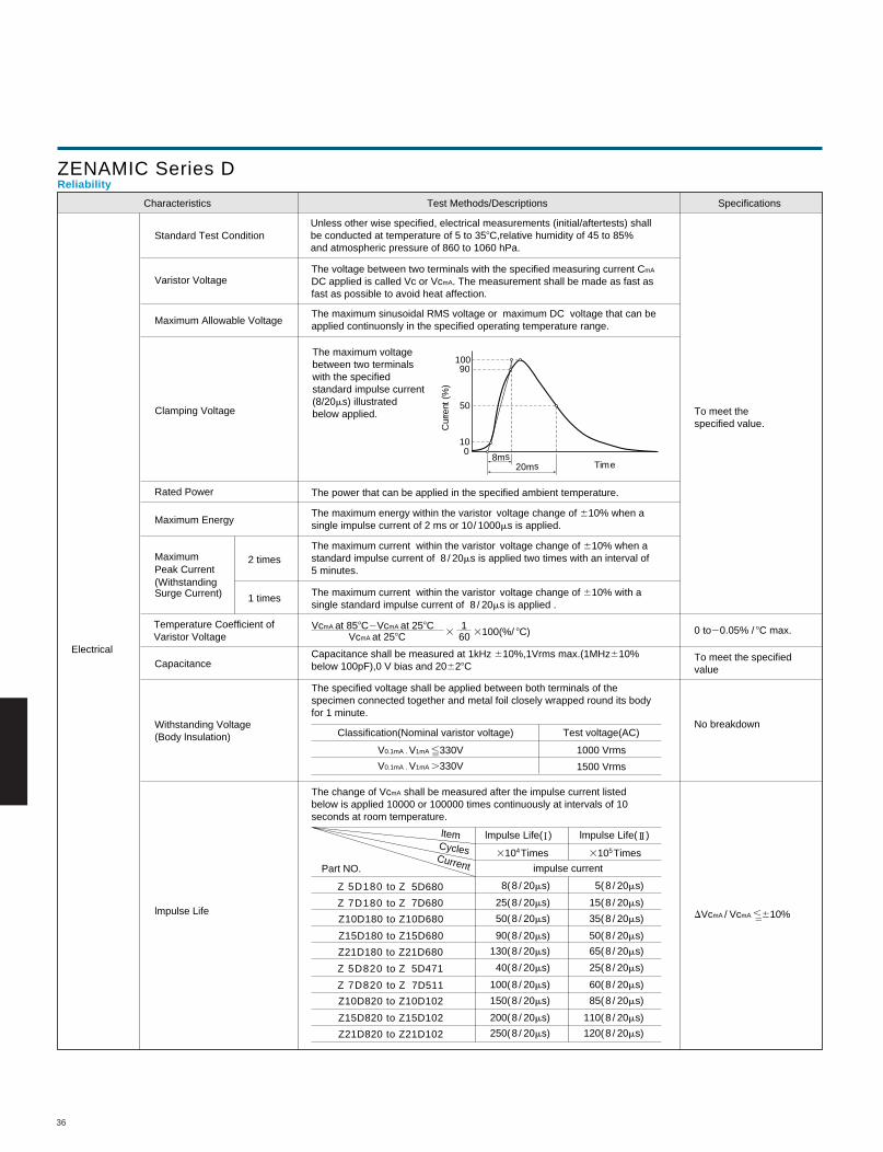
36
ZENAMIC Series DReliability
Characteristics SpecificationsTest Methods/Descriptions
Standard Test Condition
Varistor Voltage
Maximum Allowable Voltage
Maximum Energy
Clamping Voltage
Rated Power
MaximumPeak Current(WithstandingSurge Current)
Temperature Coefficient ofVaristor Voltage
Capacitance
Withstanding Voltage(Body lnsulation)
lmpulse Life
Electrical
2 times
1 times
Unless other wise specified, electrical measurements (initial/aftertests) shallbe conducted at temperature of 5 to 358C,relative humidity of 45 to 85%and atmospheric pressure of 860 to 1060 hPa.
The voltage between two terminals with the specified measuring current CmA
DC applied is called Vc or VcmA. The measurement shall be made as fast asfast as possible to avoid heat affection.
The maximum sinusoidal RMS voltage or maximum DC voltage that can beapplied continuonsly in the specified operating temperature range.
The maximum voltagebetween two terminalswith the specifiedstandard impulse current(8/20ms) illustratedbelow applied.
Time20ms8ms
100
50
90100
Cur
rent
(%
)
The power that can be applied in the specified ambient temperature.
The maximum energy within the varistor voltage change of 610% when asingle impulse current of 2 ms or 10/ 1000ms is applied.
The maximum current within the varistor voltage change of 610% when astandard impulse current of 8 / 20ms is applied two times with an interval of5 minutes.
The maximum current within the varistor voltage change of 610% with asingle standard impulse current of 8 / 20ms is applied .
VcmA at 258C
V0.1mA . V1mA ,330V
V0.1mA . V1mA .330V
60VcmA at 858C2VcmA at 258C 1
3
3104Times 3105Times
3100(%/ 8C)
Capacitance shall be measured at 1kHz 610%,1Vrms max.(1MHz610%below 100pF),0 V bias and 20628C
The specified voltage shall be applied between both terminals of thespecimen connected together and metal foil closely wrapped round its bodyfor 1 minute.
Classification(Nominal varistor voltage) Test voltage(AC)
1000 Vrms
1500 Vrms
The change of VcmA shall be measured after the impulse current listedbelow is applied 10000 or 100000 times continuously at intervals of 10seconds at room temperature. ltem
CyclesCurrent
lmpulse Life( ) lmpulse Life( )
impulse current Part NO.
Z 7D820 to Z 7D511
Z 5D820 to Z 5D471
Z15D820 to Z15D102
Z10D820 to Z10D102
Z21D820 to Z21D102
Z 7D180 to Z 7D680
Z 5D180 to Z 5D680
Z15D180 to Z15D680
Z10D180 to Z10D680
Z21D180 to Z21D680
8( 8 / 20ms)
25( 8 / 20ms)
90( 8 / 20ms)
130( 8 / 20ms)
50( 8 / 20ms)
40( 8 / 20ms)
100( 8 / 20ms)
200( 8 / 20ms)
250( 8 / 20ms)
150( 8 / 20ms)
5( 8 / 20ms)
15( 8 / 20ms)
50( 8 / 20ms)
65( 8 / 20ms)
35( 8 / 20ms)
25( 8 / 20ms)
60( 8 / 20ms)
110( 8 / 20ms)
120( 8 / 20ms)
85( 8 / 20ms)
To meet thespecified value.
0 to20.05% / 8C max.
To meet the specifiedvalue
No breakdown
DVcmA / VcmA ,610%
22
22
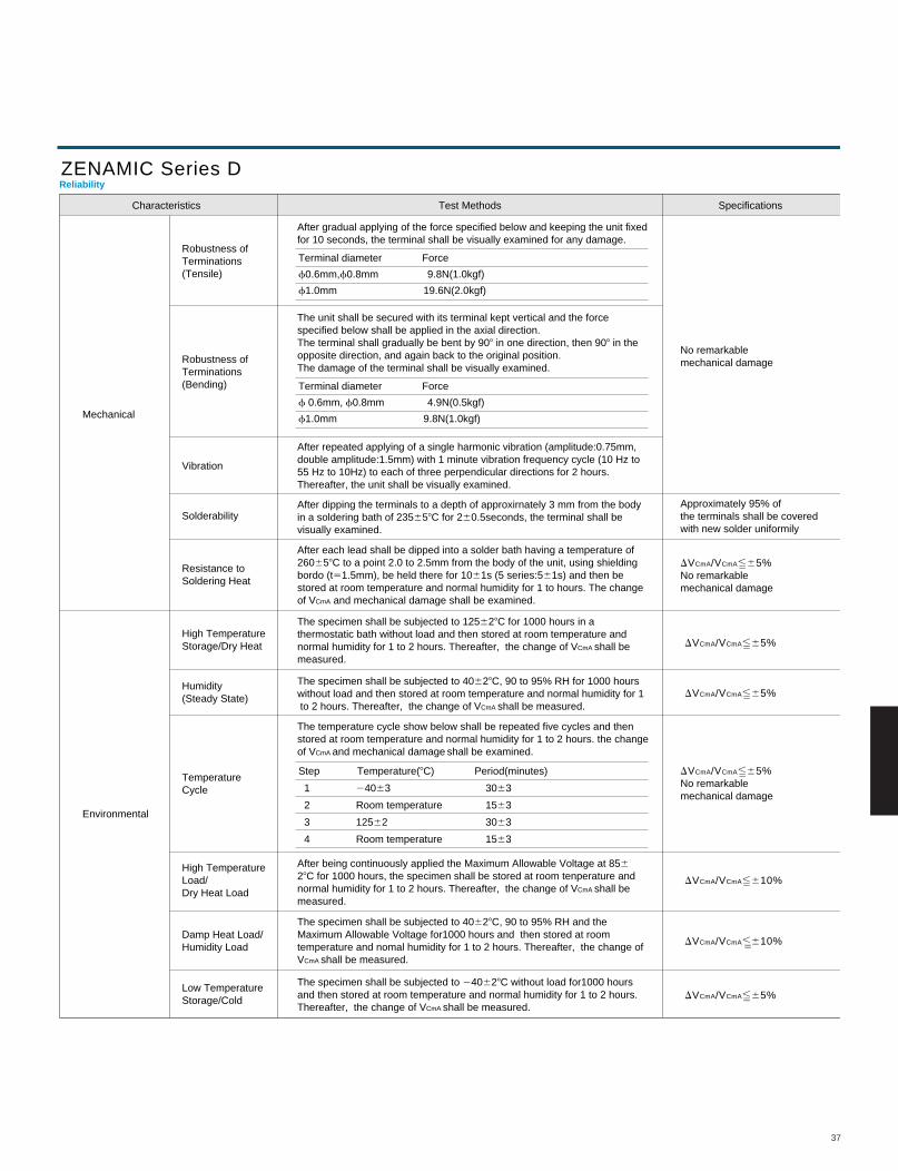
37
ReliabilityZENAMIC Series D
Characteristics Test Methods Specifications
Robustness ofTerminations(Tensile)
Robustness ofTerminations(Bending)
Humidity(Steady State)
Vibration
Solderability
Resistance toSoldering Heat
High TemperatureStorage/Dry Heat
High TemperatureLoad/Dry Heat Load
Low TemperatureStorage/Cold
Damp Heat Load/Humidity Load
TemperatureCycle
Mechanical
Environmental
After gradual applying of the force specified below and keeping the unit fixedfor 10 seconds, the terminal shall be visually examined for any damage.
Terminal diameter Force
f0.6mm,f0.8mm 9.8N(1.0kgf)
f1.0mm 19.6N(2.0kgf)
The unit shall be secured with its terminal kept vertical and the forcespecified below shall be applied in the axial direction. The terminal shall gradually be bent by 908 in one direction, then 908 in theopposite direction, and again back to the original position.The damage of the terminal shall be visually examined.
After repeated applying of a single harmonic vibration (amplitude:0.75mm,double amplitude:1.5mm) with 1 minute vibration frequency cycle (10 Hz to 55 Hz to 10Hz) to each of three perpendicular directions for 2 hours.Thereafter, the unit shall be visually examined.
The specimen shall be subjected to 125628C for 1000 hours in athermostatic bath without load and then stored at room temperature and normal humidity for 1 to 2 hours. Thereafter, the change of VCmA shall bemeasured.
After being continuously applied the Maximum Allowable Voltage at 85628C for 1000 hours, the specimen shall be stored at room tenperature andnormal humidity for 1 to 2 hours. Thereafter, the change of VCmA shall bemeasured.
The specimen shall be subjected to 40628C, 90 to 95% RH for 1000 hours without load and then stored at room temperature and normal humidity for 1 to 2 hours. Thereafter, the change of VCmA shall be measured.
The specimen shall be subjected to 40628C, 90 to 95% RH and the Maximum Allowable Voltage for1000 hours and then stored at roomtemperature and nomal humidity for 1 to 2 hours. Thereafter, the change ofVCmA shall be measured.
The specimen shall be subjected to 240628C without load for1000 hoursand then stored at room temperature and normal humidity for 1 to 2 hours.Thereafter, the change of VCmA shall be measured.
The temperature cycle show below shall be repeated five cycles and then stored at room temperature and normal humidity for 1 to 2 hours. the change of VCmA and mechanical damage shall be examined.
After each lead shall be dipped into a solder bath having a temperature of260658C to a point 2.0 to 2.5mm from the body of the unit, using shielding bordo (t51.5mm), be held there for 1061s (5 series:561s) and then bestored at room temperature and normal humidity for 1 to hours. The changeof VCmA and mechanical damage shall be examined.
After dipping the terminals to a depth of approxirnately 3 mm from the bodyin a soldering bath of 235658C for 260.5seconds, the terminal shall be visually examined.
Terminal diameter Force
f 0.6mm, f0.8mm 4.9N(0.5kgf)
f1.0mm 9.8N(1.0kgf)
Step Temperature(8C) Period(minutes)
1 24063 3063
2 Room temperature 1563
3 12562 3063
4 Room temperature 1563
Approximately 95% ofthe terminals shall be coveredwith new solder uniformily
DVCmA/VCmA,65%No remarkablemechanical damage
No remarkablemechanical damage
22
DVCmA/VCmA,65%No remarkablemechanical damage
22
22
22
22
DVCmA/VCmA,65%
DVCmA/VCmA,610%
DVCmA/VCmA,610%
DVCmA/VCmA,65%
22
DVCmA/VCmA,65%22
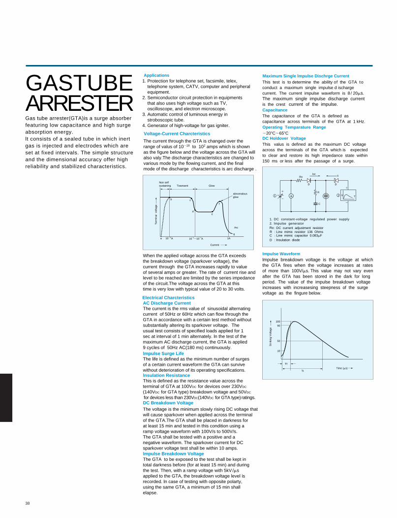
38
GASTUBEARRESTERGas tube arrester(GTA)is a surge absorberfeaturing low capacitance and high surge absorption energy.lt consists of a sealed tube in which inert gas is injected and electrodes which areset at fixed intervals. The simple structureand the dimensional accuracy offer highreliability and stabilized characteristics.
Applications Maximum Single lmpulse Dischrge Current
Capacitance
Operating Temparature Range
DC Holdover Voltage
Impulse Waveform
1. Protection for telephone set, facsimile, telex, telephone system, CATV, computer and peripheral equipment.2. Semiconductor circuit protection in equipments that also uses high voltage such as TV, oscilloscope, and electron microscope.3. Automatic control of luminous energy in stroboscopic tube. 4. Generator of high-voltage for gas igniter.
Voltage-Current Charcteristics
Electrical CharcteristicsAC Discharge Current
lmpulse Surge Life
lnsulation Resistance
DC Breakdown Voltage
Impulse Breakdown Voltage
The current through the GTA is changed over therange of valus of 10218 to 102 amps which is shownas the figure below and the voltage across the GTA willalso valy.The discharge characteristics are changed tovarious mode by the flowing current, and the finalmode of the discharge characteristics is arc discharge .
When the applied voltage across the GTA exceedsthe breakdown voltage (sparkover voltage), thecurrent through the GTA increases rapidly to valueof several amps or greater. The rate of current rise andlevel to be reached are limited by the series impedanceof the circuit.The voltage across the GTA at thistime is very low with typical value of 20 to 30 volts.
The current is the rms value of sinusoidal alternatingcurrent of 50Hz or 60Hz which can flow through theGTA in accordance with a certain test method withoutsubstantially altering its sparkover voltage. Theusual test consists of specified loads applied for 1sec at interval of 1 min alternately. ln the test of themaximum AC discharge current, the GTA is applied9 cycles of 50Hz AC(180 ms) continuously.
The life is defined as the minimum number of surgesof a certain current waveform the GTA can survivewithout deterioration of its operating specifications.
This is defined as the resistance value across theterminal of GTA at 100VDC for devices over 230VDC
(140VDC for GTA type) breakdown voltage and 50VDC
for devices less than 230VDC(140VDC for GTA type) ratings.
The voltage is the minimum slowly rising DC voltage thatwill cause sparkover when applied across the terminalof the GTA.The GTA shall be placed in darkness forat least 15 min and tested in this condition using aramp voltage waveform with 100V/s to 500V/s. The GTA shall be tested with a positive and anegative waveform. The sparkover current for DCsparkover voltage test shall be within 10 amps. The GTA to be exposed to the test shall be kept intotal darkness before (for at least 15 min) and duringthe test. Then, with a ramp voltage with 5kV /msapplied to the GTA, the breakdown voltage level isrecorded. ln case of testing with opposite polarty,using the same GTA, a minimum of 15 min shallelapse.
This test is to determine the ability o f the GTA t oconduct a maximum single impulse d ischargecurrent. The current impulse waveform is 8 / 20ms.The maximum single impulse discharge currentis the crest current of the impulse.
This valus is defined as the maximum DC voltageacross the t erminals of the GTA which is expectedto clear and restore its high impedance state within150 ms or less after the passage of a surge.
The capacitance of the GTA is defined ascapacitance across terminals of the GTA at 1 kHz.
2208C;658C
lmpulse breakdown voltage is the voltage at whichthe GTA fires when the voltage increases at ratesof more than 100V/ms. This value may not vary evenafter the GTA has been stored in the dark for longperiod. The value of the impulse breakdown voltageincreases with increasesing steepness of the surgevoltage as the fingure below.
Non selfsustaining Townsent Glow
Ter
min
al v
olta
ge
b c
d
a
e
f
g
Arc
1A102161024;1025A
abnomalousglow
100
90
50
10
Tf
TtTime (ms)
Str
ikin
g V
olta
ge
V V T
1
2
1
2
D
D
D
R
R
Ro
Ro
C
C
locli
1 2
1. DC constant-voltage regulated power supply2. lmpulse generator
: DC current adjustment resistor: Line mimic resistor 136 Ohms: Line mimic capacitor 0.083mF: lnsulation diode
Current
A
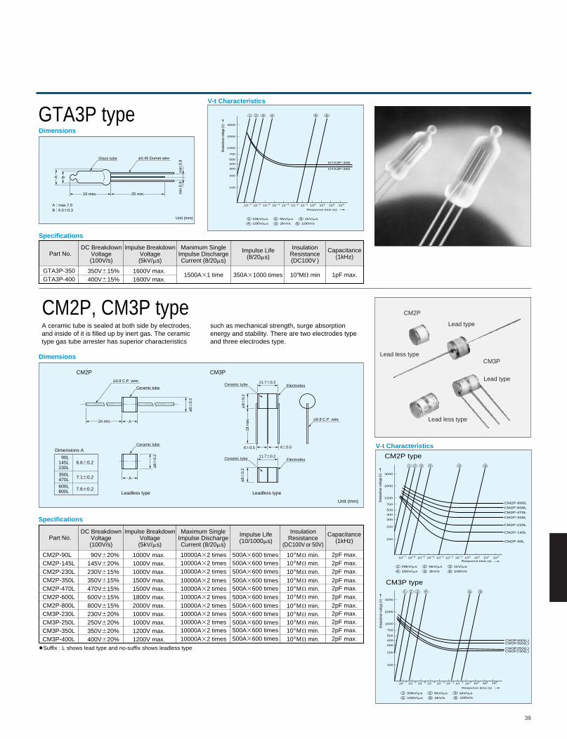
39
Dimensions
GTA3P type
Dimensions
Specifications
Specifications
CM2P, CM3P type
Glass tube f0.45 Dumet wire
min
.0.8
min
.0.8
A : max.7.0B : 6.560.3
Unit (mm)
V-t Characteristics
A ceramic tube is sealed at both side by electrodes,and inside of it is filled up by inert gas. The ceramictype gas tube arrester has superior characteristics
such as mechanical strength, surge absorptionenergy and stability. There are two electrodes typeand three electrodes type.
Ceramic tube
Dimensions A
90L145L230L
350L470L
6.660.2
7.160.2
600L800L 7.660.2
f0.8 C.P. wire
f0.8 C.P. wireElectrodesCeramic tube
f86
0.2
f86
0.2
f8 6
0.2f
860.
2
18 m
in.
11.760.2
Electrodes
Unit (mm)
Ceramic tube11.760.2
660.5 660.5
24 min. A
Ceramic tube
A
CM2P
CM2P type
CM3P type
CM3P
Leadless type Leadless type
V-t Characteristics
21 3 4 5 6
21 20kV/ms 5kV/ms 1kV/ms
100V/ms 2kV/s 100V/s
3
4 5 6
100
10
200
300
400
500
700
1000
2000
4000
27 1026 1025 1024 1023 1022 1021 100 10
Responce time (s)
1 102 103
Brea
kedo
wn vo
ltage
(V)
GTA3P-400
GTA3P-350
21 3 4 5 6
21 20kV/ms 5kV/ms 1kV/ms
100V/ms 2kV/s 100V/s
3
4 5 6
100
10
200
300
400
500
700
1000
2000
4000
27 1026 1025 1024 1023 1022 1021 100 10Responce time (s)
1 102 103
Brea
kedo
wn vo
ltage
(V)
CM2P-800L
CM2P-600L
CM2P-470L
CM2P-350L
CM2P-230L
CM2P-145L
CM2P-90L
25 min.19 max.
BA
CM2P-90LCM2P-145LCM2P-230LCM2P-350LCM2P-470LCM2P-600LCM2P-800LCM3P-230LCM3P-250LCM3P-350LCM3P-400L
90V620%145V620%230V615%350V615%470V615%600V615%800V615%230V620%250V620%350V620%400V620%
1000V max.1000V max.1000V max.1500V max.1500V max.1800V max.2000V max.1000V max.1000V max.1200V max.1200V max.
Part No.DC Breakdown
Voltage(100V/s)
Impulse BreakdownVoltage(5kV/ms)
Maximum SingleImpulse DischargeCurrent (8/20ms)
InsulationResistance
(DC100V or 50V)
Capacitance(1kHz)
Impulse Life(10/1000ms)
10000A32 times10000A32 times10000A32 times10000A32 times10000A32 times10000A32 times
10000A32 times10000A32 times10000A32 times
10000A32 times10000A32 times
500A3600 times
500A3600 times500A3600 times500A3600 times500A3600 times500A3600 times500A3600 times
500A3600 times
500A3600 times500A3600 times
500A3600 times
104MV min.
104MV min.104MV min.104MV min.
104MV min.104MV min.
104MV min.104MV min.104MV min.104MV min.104MV min.
2pF max.
2pF max.2pF max.
2pF max.2pF max.2pF max.2pF max.2pF max.
2pF max.2pF max.2pF max.
GTA3P-350GTA3P-400
350V615%400V615%
1600V max.1600V max.
Part No.DC Breakdown
Voltage(100V/s)
Impulse BreakdownVoltage(5kV/ms)
Manimum SingleImpulse DischargeCurrent (8/20ms)
InsulationResistance(DC100V )
Capacitance(1kHz)
Impulse Life(8/20ms)
1500A31 time 350A31000 times 104MV min 1pF max.
Suffix : L shows lead type and no-suffix shows leadless type
21 3 4 5 6
27 26 25 24 23 22 21 0 1 2 3
21 20kV/ms 5kV/ms 1kV/ms
100V/ms 2kV/s 100V/s
3
4 5 6
100
10
200
300
400
500
700
1000
2000
4000
10 10 10 10 10 10 10 10
Responce time (s)
10 10
Brea
kedo
wn vo
ltage
(V)
CM3P400(L)CM3P350(L)
CM3P250(L)CM3P230(L)
CM2P
CM3P
Lead type
Lead type
Lead less type
Lead less type
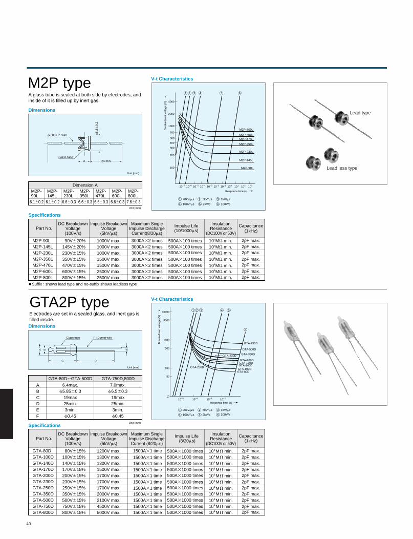
40
Dimensions
A glass tube is sealed at both side by electrodes, andinside of it is filled up by inert gas.
M2P type
Dimensions
Specifications
Specifications
GTA2P type
Unit (mm)
Unit (mm)
Unit (mm)
Unit (mm)
Electrodes are set in a sealed glass, and inert gas isfilled inside.
21 3 4 5 6
21 20kV/ms 5kV/ms 1kV/ms
100V/ms 2kV/s 100V/s
3
4 5 6
V-t Characteristics
100
10
200
300
400
500
700
1000
2000
4000
27 1026 1025 1024 1023 1022 1021 100 10
Responce time (s)
1 102 103
Bre
aked
own
volta
ge (
V)
M2P-800L
M2P-600LM2P-470L
M2P-350L
M2P-230L
M2P-145L
M2P-90L
GTA-750D
GTA-500D
GTA-350D
GTA-200D
GTA-230D
GTA-250D
GTA-170DGTA-140D
GTA-100DGTA-80D
f0.8 C.P. wire f8.
260.
2
Glass tube24 min.A
21 3 4 5
6
21 20kV/ms 5kV/ms 1kV/ms
100V/s100V/ms 2kV/s
3
4 5 6
V-t Characteristics
10
50
100
500
1000
5000
10000
1022102410261028
Responce time (s)
Bre
aked
own
volta
ge (
V)
Dimension AM2P-90L
6.160.2
M2P-145L
6.160.2
M2P-230L
6.660.3
M2P-350L
6.660.3
M2P-470L
6.660.3
M2P-600L
6.660.3
M2P-800L
7.660.3
Glass tube F : Dumet wire
C D
B EA
ABCDEF
GTA-80D;GTA-500D GTA-750D,800D
6.4max.f5.8560.3
19max25min.3min.f0.45
7.0max.f6.560.3
19max25min.3min.f0.45
GTA-80DGTA-100DGTA-140DGTA-170DGTA-200DGTA-230DGTA-250DGTA-350DGTA-500DGTA-750DGTA-800D
80V615%100V615%140V615%170V615%200V615%230V615%250V615%350V615%500V615%750V615%800V615%
1200V max.1300V max.1300V max.1500V max.1700V max.1700V max.1700V max.2000V max.2100V max.4500V max.5000V max.
Part No.DC Breakdown
Voltage(100V/s)
Impulse BreakdownVoltage(5kV/ms)
Maximum SingleImpulse DischargeCurrent (8/20ms)
InsulationResistance
(DC100V or 50V)
Capacitance(1kHz)
Impulse Life (8/20ms)
1500A31 time
1500A31 time
1500A31 time1500A31 time1500A31 time1500A31 time
1500A31 time1500A31 time1500A31 time1500A31 time1500A31 time
500A31000 times500A31000 times500A31000 times500A31000 times500A31000 times500A31000 times
500A31000 times500A31000 times500A31000 times500A31000 times500A31000 times
104MV min.
104MV min.104MV min.104MV min.104MV min.104MV min.
104MV min.104MV min.104MV min.104MV min.104MV min.
2pF max.2pF max.2pF max.2pF max.2pF max.2pF max.
2pF max.2pF max.2pF max.2pF max.2pF max.
M2P-90LM2P-145LM2P-230LM2P-350LM2P-470LM2P-600LM2P-800L
90V620%145V620%230V615%350V615%470V615%600V615%800V615%
1000V max.1000V max.1000V max.1500V max.1500V max.2500V max.2500V max.
Part No.DC Breakdown
Voltage(100V/s)
Impulse BreakdownVoltage(5kV/ms)
Maximum SingleImpulse Discharge
Current(8/20ms)
InsulationResistance
(DC100V or 50V)
Capacitance(1kHz)
Impulse Life(10/1000ms)
3000A32 times
3000A32 times3000A32 times3000A32 times
3000A32 times3000A32 times3000A32 times
500A3100 times
500A3100 times500A3100 times500A3100 times
500A3100 times500A3100 times500A3100 times
104MV min.
104MV min.104MV min.104MV min.
104MV min.104MV min.104MV min.
2pF max.
2pF max.2pF max.2pF max.
2pF max.2pF max.2pF max.
Suffix : shows lead type and no-suffix shows leadless type
Lead type
Lead iess type
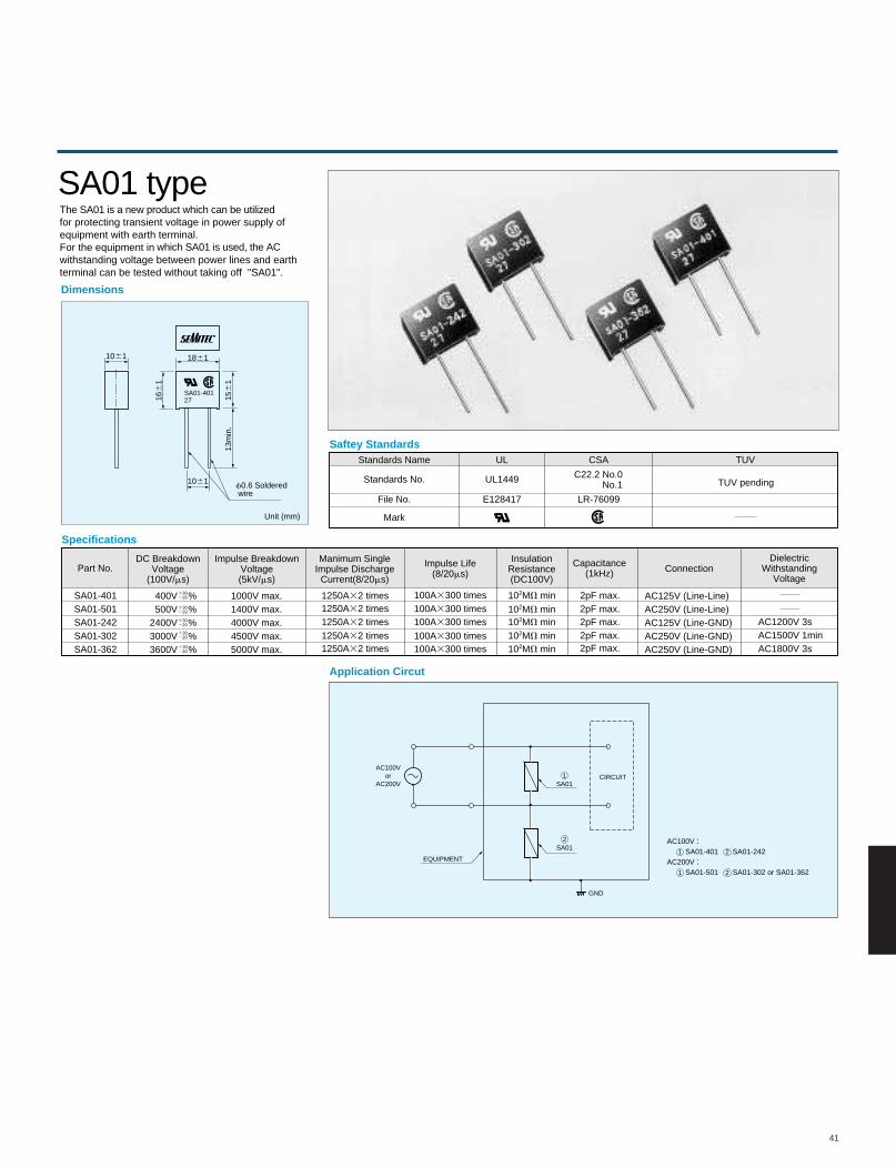
41
Specifications
SA01-401SA01-501SA01-242SA01-302SA01-362
400V %500V %
2400V %3000V %3600V %
1000V max.1400V max.4000V max.4500V max.5000V max.
AC125V (Line-Line)AC250V (Line-Line)AC125V (Line-GND)AC250V (Line-GND)AC250V (Line-GND)
AC1200V 3sAC1500V 1minAC1800V 3s
Part No.DC Breakdown
Voltage(100V/ms)
Impulse BreakdownVoltage(5kV/ms)
Manimum SingleImpulse Discharge
Current(8/20ms)
InsulationResistance(DC100V)
Capacitance(1kHz) Connection
DielectricWithstanding
Voltage
Impulse Life(8/20ms)
SA01 typeThe SA01 is a new product which can be utilized for protecting transient voltage in power supply ofequipment with earth terminal.For the equipment in which SA01 is used, the AC withstanding voltage between power lines and earth terminal can be tested without taking off "SA01".
1250A32 times
1250A32 times1250A32 times
1250A32 times1250A32 times
100A3300 times100A3300 times100A3300 times
100A3300 times100A3300 times
102MV min
102MV min102MV min
102MV min102MV min
2pF max.
2pF max.2pF max.
2pF max.2pF max.
Saftey Standards
Application Circut
Dimensions
Standards Name
Standards No.
File No.
Mark
UL
UL1449
E128417
CSA
C22.2 No.0No.1
LR-76099
TUV
TUV pendingf0.6 Soldered wire
1061
1061 1861
SA01-4012716
61
156
113
min
.
Unit (mm)
EQUIPMENT
SA012
2
SA011
1
21
CIRCUITAC100V
orAC200V
GND
AC100V : SA01-401 SA01-242AC200V : SA01-501 SA01-302 or SA01-362
130220
130220
130220
130220
130220
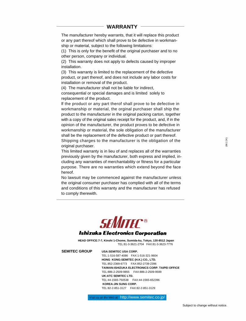
WARRANTY
SEMITEC GROUP USA:SEMITEC USA CORP.TEL:1-516-587-4086 FAX:1-516-321-9604HONG KONG:SEMITEC (H.K.) CO., LTD.TEL:852-2369-6773 FAX:852-2739-2396TAIWAN:ISHIZUKA ELECTRONICS CORP. TAIPEI OFFICETEL:886-2-2509-9855 FAX:886-2-2509-9599
UK:ATC SEMITEC LTD.TEL:44-1565-750538 FAX:44-1565-652396 KOREA:JIN SUNG CORP.TEL:82-2-851-3127 FAX:82-2-851-3129
The manufacturer hereby warrants, that it will replace this productor any part thereof which shall prove to be defective in workman-ship or material, subject to the following limitations:(1) This is only for the benefit of the original purchaser and to no other person, company or individual.(2) This warranty does not apply to defects caused by improperinstallation.(3) This warranty is limited to the replacement of the defectiveproduct, or part thereof, and does not include any labor costs forinstallation or removal of the product.(4) The manufacturer shall not be liable for indirect,consequential or special damages and is limited solely toreplacement of the product.lf the product or any part therof shall prove to be defective inworkmanship or material, the orginal purchaser shall ship theproduct to the manufacturer in the original packing carton, togetherwith a copy of the original sales receipt for the product, and, if in theopinion of the manufacturer, the product proves to be defective inworkmanship or material, the sole obligation of the manufacturershall be the replacement of the defective product or part thereof.Shipping charges to the manufacturer is the obligation of theoriginal purchaser.This limited warranty is in lieu of and replaces all of the warrantiespreviously given by the manufacturer, both express and implied, in-cluding any warranties of merchantability or fitness for a particularpurpose. There are no warranties which extend beyond the facehereof.No lawsuit may be commenced against the manufacturer unlessthe original consumer purchaser has complied with all of the termsand conditions of this warranty and the manufacturer has refusedto comply therewith.
(98.
2.2K
)
Subject to change without notice.
HEAD OFFICE:7-7, Kinshi 1-Chome, Sumida-ku, Tokyo, 130-8512 Japan
Visit us on the Web at http://www.semitec.co.jp/
TEL:81-3-3621-2704 FAX:81-3-3623-7776