Embed Size (px)
Citation preview
Your number one name for EMC
for chassis- andPCB-mounting
SINGLE PHASE FILTERS
SCHAFFNER
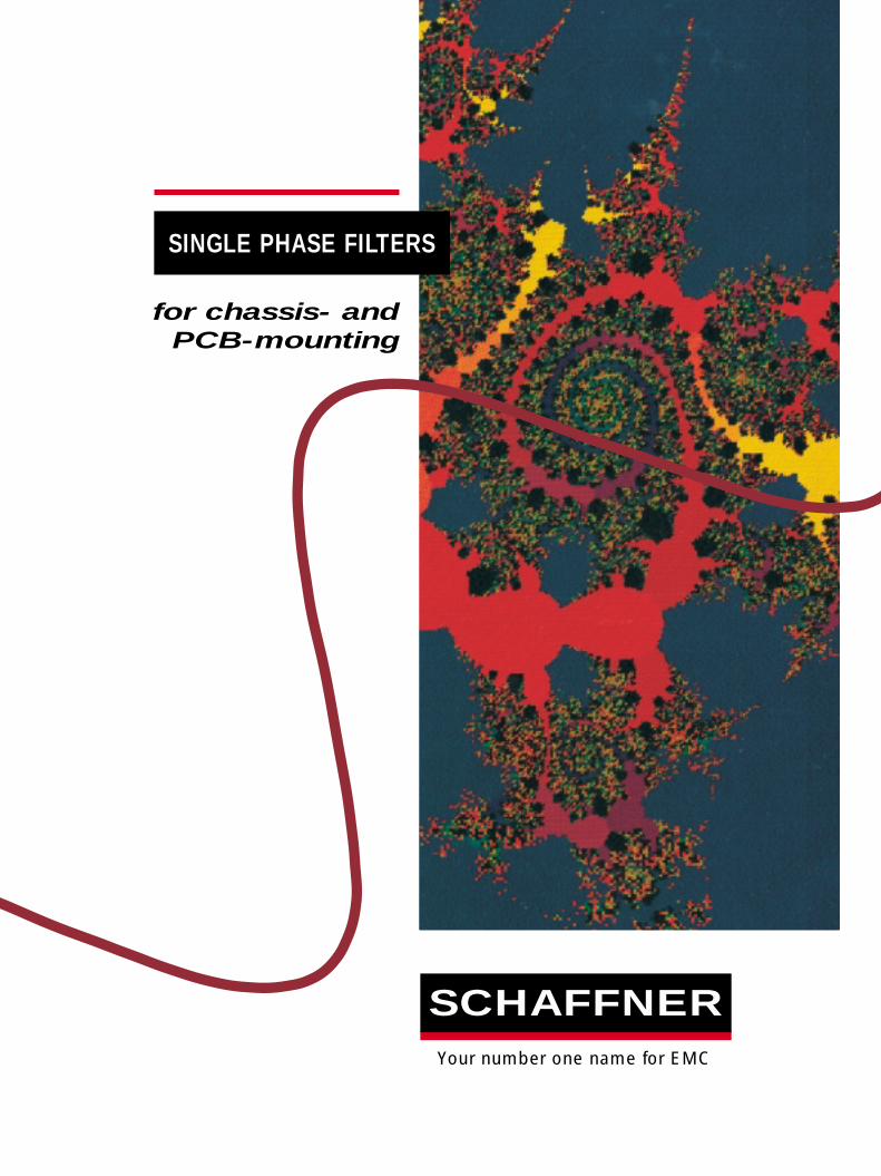
Single-phase filters for chassis- and PCB-mounting
CONTENTS General informationIntroduction to single-phase filters ............2
Filter selection chart ...................................3
Understanding EMC standards &
filter specifications......................................4
EMC measurement & engineering
services .......................................................8
Ordering information...................................9
Technical dataFN 22 .........................................................10
FN 250 .......................................................12
FN 332 .......................................................14
FN 343 .......................................................16
FN 346 .......................................................18
FN 350 .......................................................20
FN 352Z.....................................................22
FN 357 .......................................................24
FN 401 .......................................................26
FN 402 .......................................................28
FN 405 .......................................................30
FN 406 .......................................................32
FN 410 .......................................................34
FN 420 .......................................................36
FN 610 .......................................................38
FN 612 .......................................................40
FN 660 .......................................................42
FN 670 .......................................................44
FN 680 .......................................................46
FN 685 .......................................................48
FN 700Z.....................................................50
FN 9675 .....................................................52
Mechanical Data ..............................54 - 60
Addresses and contact information ........61
SCHAFFNER
In today’s world, more electrical energy is
being generated at increasing levels of
power, and more and more low power
energy is being used for the transmission
and processing of data. The result is vastly
increased ‘electronic smog’ or noise. This
noise can disrupt, and even destroy,
electronic devices: an unacceptable
situation, and shortly an illegal one in
certain markets. The electronics
industry must strive to protect
equipment against such ‘noise’.
Noise, or interference, travels two ways.
Switches - such as semiconductors - can
emit interference, and be susceptible to it.
The same is true for data processing
equipment. The most common method of
protection is the use of powerline filters
coupled with screening or gasketting
materials.
The mains, or powerline, filter is the key
element in eliminating mains-borne
interference. This filter not only has to
meet the requirements of electro-magnetic
compatibility (EMC), but safety aspects as
well. For some applications, the filter also
has to prevent the radiation of classified
information from the mains line (‘Tempest’
applications). Other applications require a
filter to protect equipment from
destructive voltages on the power line, like
those caused by lightning or nuclear
explosion (NEMP).
Schaffner’s breadth of product range, the
high attenuation characteristics of our
filters under various load
conditions, our dedication to
quality - and above all our
organization’s unique
experience in filter design
and manufacturing -
spanning more than 25
years - is your guarantee of
excellence.
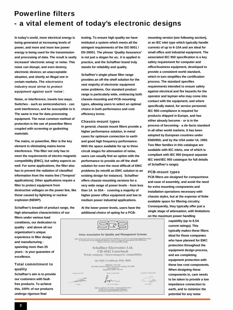
Total commitment toqualitySchaffner’s aim is to provide
our customers with fault-
free products. To achieve
this, 100% of our products
undergo rigorous final
testing. To ensure high quality we have
instituted a system which meets all the
stringent requirements of the ISO 9001 /
EN 29001. The phrase ‘Quality Assurance’
is not just a slogan for us; it is applied in
practice, and the Schaffner brand truly
stands for reliability and quality.
Schaffner’s single-phase filter range
provides an off-the-shelf solution for the
vast majority of electronic equipment
noise problems. Our standard product
range is particularly wide, embracing both
chassis-mounting and PCB-mounting
types, allowing users to select an optimal
choice in both performance and cost
efficiency terms.
Chassis-mount typesIn general, chassis mount filters provide a
higher performance solution, in metal
cases for optimum connection to earth
and good high frequency performance.
With the space available for up to three
circuit stages for attenuation of noise,
users can usually find an option with the
performance to provide an off the shelf
solution for even the most difficult of EMC
problems (to retrofit an EMC solution to an
existing design for instance). Schaffner
offers chassis-mounting versions for a
very wide range of power levels - from less
than 1A to 55A - covering a majority of
higher power office equipment and low to
medium power industrial applications.
At the lower power levels, users have the
additional choice of opting for a PCB-
mounting version (see following section),
or an IEC inlet type which typically handle
currents of up to 6-10A and are ideal for
small office and industrial equipment. The
associated IEC 950 specification is a key
safety requirement for computer and
office/business equipment, developed to
provide a consistent world standard,
which in turn simplifies the certification
process. The standard specifies
requirements intended to ensure safety
against electrical and fire hazards for the
operator and layman who may come into
contact with the equipment, and where
specifically stated, for service personnel.
IEC 950-compliance is required for
products shipped in Europe, and has
either already become - or is in the
process of becoming - a de-facto standard
in all other world markets. It has been
adopted by European countries under
EN60950, and by the USA under UL 1950.
Two filter families in this catalogue are
available with IEC inlets, one of which is
compliant with IEC 950 (request separate
IEC inlet/IEC 950 catalogue for full details
of Schaffner’s range).
PCB-mount typesPCB filters are designed for compactness
and ease of assembly, and avoid the need
for extra mounting components and
installation operations necessary with
chassis styles, but at the expense of finite
available space for filtering circuitry.
Consequently, they typically offer just a
single stage of attenuation, with limitations
on the maximum power handling
capability (up to 6.5A
current ratings). This
typically makes these filters
ideal for those companies
who have planned for EMC
protection throughout the
equipment design process,
and are completing
equipment protection with
these low cost components.
When designing these
components in, care needs
to be taken to provide a low
impedance connection to
earth, and to minimize the
potential for any noise
2
Powerline filters- a vital element of today’s electronic designs
Filter family
FN 22
FN 250, 350
FN 332
FN 343
FN 346
FN 352Z
FN 401 ...406
FN 410
FN 610, 612
FN 660, 670
FN 680, 685
FN 700Z
FN 9675/76
3
radiation from the mains inlet connection.
Time to marketThe key reasons for choosing ready-made
filters are convenience, compactness and
cost. Although you can design your own
mains inlet and filter using discrete
components, or have a custom solution
designed and assembled for you, the
timescales involved in getting safety
approvals will often rule this approach
out, especially for higher volume products
such as photocopiers which necessitate
very fast design cycles.
Ready-made chassis- and PCB-mount
filters provide a convenient single-source
solution, with the additional benefits of
custom-engineered housings for
compactness. The following guide to
Schaffner’s single-phase products - with
brief details on key parameters - will help
you to identify one or more filters for
closer review of specifications (there are
some 170 options available in the total
range). From this initial selection, a
review of the circuit diagram and detailed
specifications in the following pages will
tell you if the module is suitable for your
application, allowing you to choose a unit
(or units) for trial.
Schaffner is one of the world’s leading
suppliers of EMC equipment, and our
extensive experience allows us to offer
one of the widest EMC filtering ranges
available - spanning both general-
purpose and specialist needs like
TEMPEST. This breadth of range greatly
assists designers, allowing optimum
choices to be made, whether the need is
for maximum performance or lowest cost.
Our worldwide organization - with its
numerous application engineering teams -
will gladly help your engineers select and
trial suitable power line filters, and
provides an efficient support structure to
assist multi-national organizations with
dispersed design and manufacturing
facilities.
As a review of this catalogue will show
you, Schaffner designs power line filters
using high grade components in order to
optimize reliability. And we construct
modules under the control of the most
advanced quality system. Whichever
power line filter you choose, you can rely
on Schaffner’s quality.
5 10 15 20 25 30 35 40 45 505 10 15 20 25 30 35 40 45 50
1 9standard
current rating (A)
Attenuation
middle high very high
with
ear
th li
ne c
hoke
with
ove
rvo
ltag
e p
rote
ctio
n
2 st
age
3 st
age
with
IEC
inle
t
for
SM
PS
for
med
ical
eq
uip
men
t
NE
MP
, TE
MP
ES
T
for
pri
nted
-cir
cuit
mo
untin
g
for
mo
tor
dri
ves
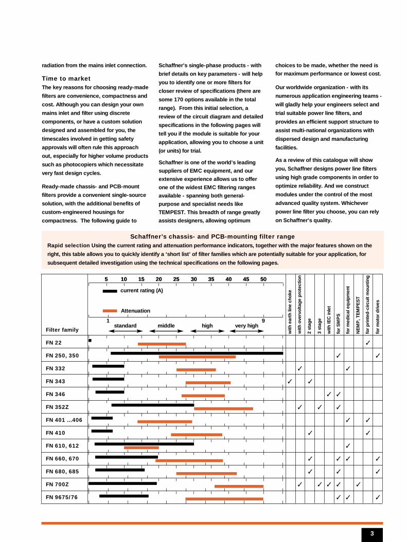
Schaffner’s chassis- and PCB-mounting filter rangeRapid selection Using the current rating and attenuation performance indicators, together with the major features shown on the
right, this table allows you to quickly identify a ‘short list’ of filter families which are potentially suitable for your application, for
subsequent detailed investigation using the technical specifications on the following pages.
This section introduces thestandards and regulationsassociated with EMC protection,and provides detailed informationto help you understand filter design and specifications. It willhelp you identify for your applica-tion the right specifications andtype of filter.
Interference protection standardsUntil recently most countries have had
their own regulations and standards
governing electro-magnetic interference
(EMI) or radio frequency interference (RFI).
However, on the 1 January 1992 the
European Directive 89/336/EMC on
electro-magnetic compatibility (EMC)
came into force. This directive brings a
common approach to EMC to every
member state of the European Union.
Common standards will be used
throughout Europe to ensure that
technical trade barriers are removed. As
well as controlling EMI emissions from
equipment, the directive also calls for
equipment to be immune to external
electro-magnetic disturbances.
The task of elaborating the standards to
be used has been given to the European
organisation called CENELEC. The
member countries of CENELEC are:
Austria Italy
Belgium Luxembourg
Denmark Netherlands
Finland Norway
France Portugal
Germany Spain
Greece Sweden
Iceland Switzerland
Ireland United Kingdom
Most of the European standards will be
based upon international standards from
CISPR and IEC. The numbering system
used in the European standards is:
EN xx yyy
EN = European Norm. xx = 50 denotes that
the standard is a standard of CENELEC
origin; xx = 55 means the standard is
based on a CISPR standard yyy; xx = 60
means the standard is based on an IEC
standard yyy.
Once the European standard is complete
the individual members of the European
Union will produce national harmonised
standards and will usually give their
harmonised standard a national number,
eg the British harmonised standard of EN
55011 is BS EN 55011.
Types of standards:Basic standards describe the general
and fundamental rules for meeting the
requirements. Terminology, phenomena,
compatibility levels, measurement, test
techniques and classification of EM
environments are so described within.
Generic standards refer to specific
environments. They set minimal EMI levels
which equipment in these environments
must meet. Where no product specific
standards exist then the generic standards
are to be used. Generic standards
describe household and industrial EMI
environments.
Products standards are for specific
products or product groups. These
standards are coordinated with the
generic standards.
In countries outside Europe other
standards will be used, such as the FCC in
the USA. Table 1 shows the main
European standards.
Permissible noise limitsThe various standards set down limits for
conducted EMI emissions. These limits are
measured in voltage and given in dBµV
where 0dB is 1µV. The interference is
measured using measurement equipment
which has defined bandwidths and
receivers. The two receivers used are a
quasi-peak detector, and an average
detector.
To ensure repeatability of the
measurements, the impedance of the
mains supply must be constant. The
standards calls for a defined artificial
mains network - sometimes called a line
impedance stabilisation network (LISN) -
which gives a defined impedance to the
noise and also helps filter any noise on the
mains which may affect the
measurements.
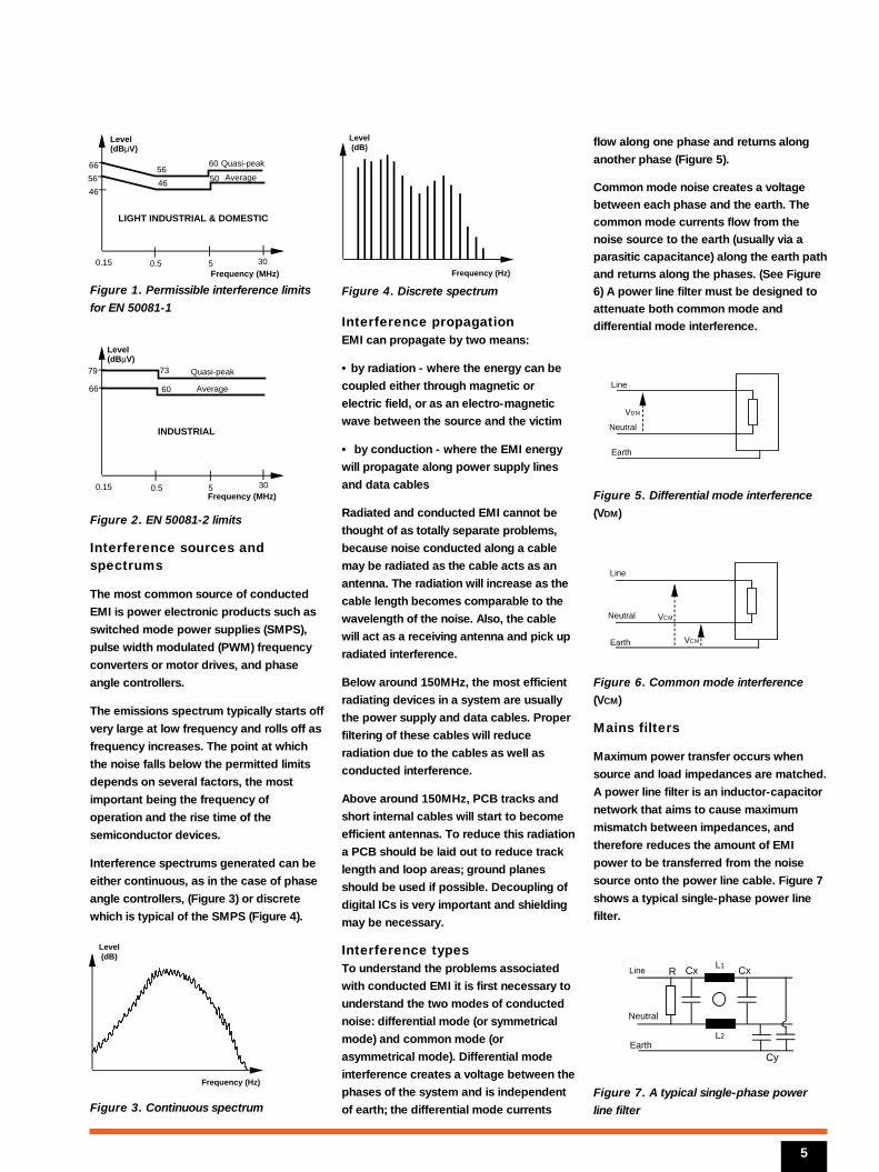
Figure 1 shows the limits of EN 50081-1
the European generic standard for
residential, commercial and light industrial
environments, and Figure 2 of EN 50081-2,
the European generic standard for the
industrial environment.
Above 30MHz, radiated noise interference
is measured instead of conducted noise.
This takes place on an open field test site
using defined antennas.
Understanding EMC standards and filter specifications
4
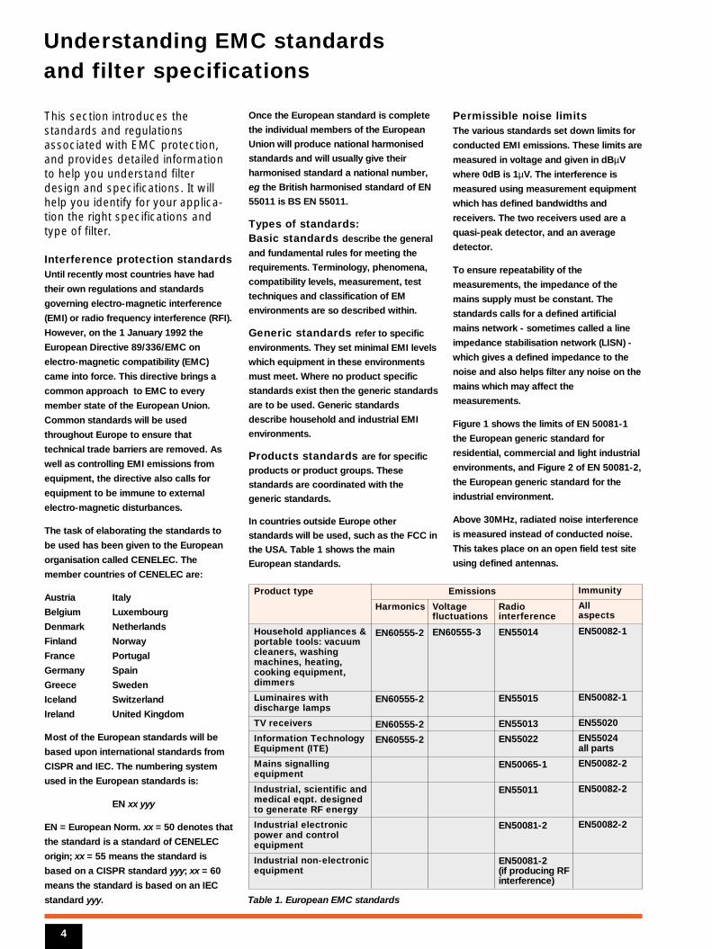
Table 1. European EMC standards
Product type
Household appliances &portable tools: vacuumcleaners, washingmachines, heating,cooking equipment,dimmers
Luminaires with discharge lamps
TV receivers
Information TechnologyEquipment (ITE)
Mains signallingequipment
Industrial, scientific andmedical eqpt. designed to generate RF energy
Industrial electronic power and controlequipment
Industrial non-electronicequipment
Harmonics
EN60555-2
EN60555-2
EN60555-2
EN60555-2
Voltagefluctuations
EN60555-3
Radiointerference
EN55014
EN55015
EN55013
EN55022
EN50065-1
EN55011
EN50081-2
EN50081-2(if producing RFinterference)
Immunity
Allaspects
EN50082-1
EN50082-1
EN55020
EN55024all parts
EN50082-2
EN50082-2
EN50082-2
Emissions
Frequenz Hz
Pegel dB
Figure 1. Permissible interference limits
for EN 50081-1
Figure 2. EN 50081-2 limits
Interference sources andspectrums
The most common source of conducted
EMI is power electronic products such as
switched mode power supplies (SMPS),
pulse width modulated (PWM) frequency
converters or motor drives, and phase
angle controllers.
The emissions spectrum typically starts off
very large at low frequency and rolls off as
frequency increases. The point at which
the noise falls below the permitted limits
depends on several factors, the most
important being the frequency of
operation and the rise time of the
semiconductor devices.
Interference spectrums generated can be
either continuous, as in the case of phase
angle controllers, (Figure 3) or discrete
which is typical of the SMPS (Figure 4).
Figure 3. Continuous spectrum
Figure 4. Discrete spectrum
Interference propagationEMI can propagate by two means:
• by radiation - where the energy can be
coupled either through magnetic or
electric field, or as an electro-magnetic
wave between the source and the victim
• by conduction - where the EMI energy
will propagate along power supply lines
and data cables
Radiated and conducted EMI cannot be
thought of as totally separate problems,
because noise conducted along a cable
may be radiated as the cable acts as an
antenna. The radiation will increase as the
cable length becomes comparable to the
wavelength of the noise. Also, the cable
will act as a receiving antenna and pick up
radiated interference.
Below around 150MHz, the most efficient
radiating devices in a system are usually
the power supply and data cables. Proper
filtering of these cables will reduce
radiation due to the cables as well as
conducted interference.
Above around 150MHz, PCB tracks and
short internal cables will start to become
efficient antennas. To reduce this radiation
a PCB should be laid out to reduce track
length and loop areas; ground planes
should be used if possible. Decoupling of
digital ICs is very important and shielding
may be necessary.
Interference typesTo understand the problems associated
with conducted EMI it is first necessary to
understand the two modes of conducted
noise: differential mode (or symmetrical
mode) and common mode (or
asymmetrical mode). Differential mode
interference creates a voltage between the
phases of the system and is independent
of earth; the differential mode currents
flow along one phase and returns along
another phase (Figure 5).
Common mode noise creates a voltage
between each phase and the earth. The
common mode currents flow from the
noise source to the earth (usually via a
parasitic capacitance) along the earth path
and returns along the phases. (See Figure
6) A power line filter must be designed to
attenuate both common mode and
differential mode interference.
Figure 5. Differential mode interference
(VDM)
Figure 6. Common mode interference
(VCM)
Mains filters
Maximum power transfer occurs when
source and load impedances are matched.
A power line filter is an inductor-capacitor
network that aims to cause maximum
mismatch between impedances, and
therefore reduces the amount of EMI
power to be transferred from the noise
source onto the power line cable. Figure 7
shows a typical single-phase power line
filter.
Figure 7. A typical single-phase power
line filter
5
0.15Frequency (MHz)
0.5 5 30
Level(dBµV)
66
79 73
60
Quasi-peak
Average
INDUSTRIAL
VDM
Line
Neutral
Earth
VCM
VCM
Line
Neutral
Earth
Level(dBµV)
66 Quasi-peak
Average
LIGHT INDUSTRIAL & DOMESTIC
46
56
0.15Frequency (MHz)
0.5 5 30
60
5056
46
Frequency Hz
Level dB
Live
Neutral
Earth
L1
L2
Level dB
Frequency Hz
R Cx Cx
Cy
Line
Level(dB)
Frequency (Hz)
Level(dB)
Frequency (Hz)
The inductors L1 and 2 are usually wound
- in a current compensated fashion - on a
toroidal core. This winding method allows
flux due to differential mode currents and
mains currents to cancel each other, while
common mode currents will be added
together. This gives a large inductance to
common mode currents and ensures that
the inductor will not be saturated by the
large magnetic flux produced by the mains
current.
The capacitors placed between the
phases, known as ‘X’ class capacitors
must offer a high pulse voltage rating and
are used to attenuate differential mode
interference. The capacitors between the
phase lines and earth, known as ‘Y’ class
capacitors must have a more stringent
rating and are used to attenuate common
mode interference. The value of the Y
capacitor is restricted by the permissible
leakage current allowed. The maximum
leakage current is governed by standards
and regulations and depends upon the
type of equipment. The leakage current is
given by:
IL=2 · π· U · f · c
where IL is the leakage current; U the
voltage across the capacitor; f the
frequency of the mains voltage across the
capacitor, and c the capacitance.
Mains filters should be mounted as close
as possible to power entry so that high
frequency interference does not bypass
the filter. IEC inlet modules are ideally
suited for this task.
To achieve higher attenuation or an
increase in the effective working
frequency range more complex filters than
the one shown in Figure 7 can be made
using more common mode or differential
mode inductors and capacitors.
Insertion lossThe insertion loss characteristics for each
filter shown on the datasheets, are
measured in accordance with CISPR 17.
Two test conditions are employed: one
using 50Ω termination impedances, the
other using an input impedance of 0.1Ωand an output impedance of 100Ω (and
reverse conditions). Both test methods
can be found in section 4.2 of CISPR 17,
and in ‘CISPR 17 Measurements’, a
document published by Schaffner and
available on request.
In the 50Ω test condition, two sets of
insertion loss curves are given. One is
common (asymmetrical) mode insertion
loss. The other one for differential mode
interference.
In general, Schaffner filters perform
against common mode interference in the
manner shown by the 50Ω insertion loss
tests. But in differential mode, the 50Ω is
not representative of effective
performance. Therefore Schaffner includes
the 0.1/100Ω differential mode test to
show how a filter will perform in real life
situations.
For this 0.1/100Ω test condition, only
differential mode insertion loss is given. In
this test, mismatched impedances
illustrate effective filter performance in a
piece of equipment.
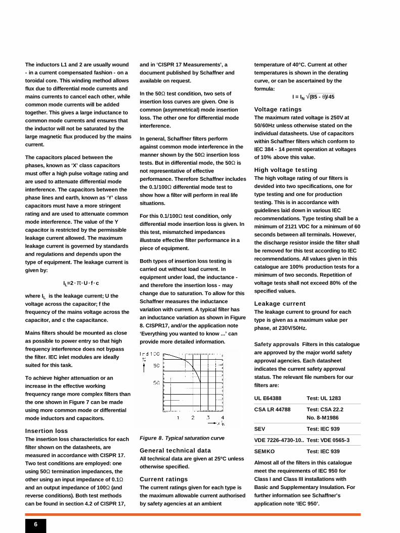
Both types of insertion loss testing is
carried out without load current. In
equipment under load, the inductance -
and therefore the insertion loss - may
change due to saturation. To allow for this
Schaffner measures the inductance
variation with current. A typical filter has
an inductance variation as shown in Figure
8. CISPR17, and/or the application note
‘Everything you wanted to know ...’ can
provide more detailed information.
Figure 8. Typical saturation curve
General technical dataAll technical data are given at 25ºC unless
otherwise specified.
Current ratingsThe current ratings given for each type is
the maximum allowable current authorised
by safety agencies at an ambient
temperature of 40°C. Current at other
temperatures is shown in the derating
curve, or can be ascertained by the
formula:
I = IN √(85 - θ)/45
Voltage ratingsThe maximum rated voltage is 250V at
50/60Hz unless otherwise stated on the
individual datasheets. Use of capacitors
within Schaffner filters which conform to
IEC 384 - 14 permit operation at voltages
of 10% above this value.
High voltage testingThe high voltage rating of our filters is
devided into two specifications, one for
type testing and one for production
testing. This is in accordance with
guidelines laid down in various IEC
recommendations. Type testing shall be a
minimum of 2121 VDC for a minimum of 60
seconds between all terminals. However,
the discharge resistor inside the filter shall
be removed for this test according to IEC
recommendations. All values given in this
catalogue are 100% production tests for a
minimum of two seconds. Repetition of
voltage tests shall not exceed 80% of the
specified values.
Leakage currentThe leakage current to ground for each
type is given as a maximum value per
phase, at 230V/50Hz.
Safety approvals Filters in this catalogue
are approved by the major world safety
approval agencies. Each datasheet
indicates the current safety approval
status. The relevant file numbers for our
filters are:
UL E64388 Test: UL 1283
CSA LR 44788 Test: CSA 22.2
No. 8-M1986
SEV Test: IEC 939
VDE 7226-4730-10.. Test: VDE 0565-3
SEMKO Test: IEC 939
Almost all of the filters in this catalogue
meet the requirements of IEC 950 for
Class I and Class III installations with
Basic and Supplementary Insulation. For
further information see Schaffner’s
application note ‘IEC 950’.
6
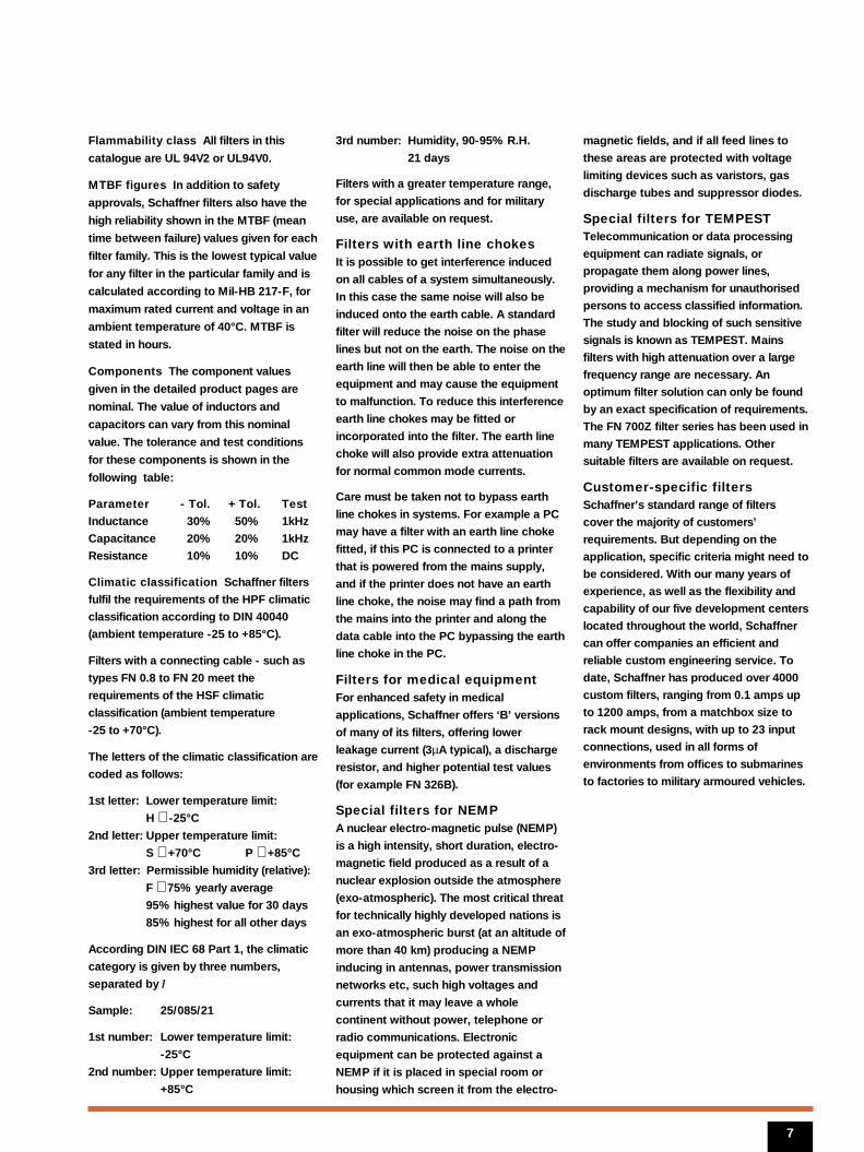
Flammability class All filters in this
catalogue are UL 94V2 or UL94V0.
MTBF figures In addition to safety
approvals, Schaffner filters also have the
high reliability shown in the MTBF (mean
time between failure) values given for each
filter family. This is the lowest typical value
for any filter in the particular family and is
calculated according to Mil-HB 217-F, for
maximum rated current and voltage in an
ambient temperature of 40°C. MTBF is
stated in hours.
Components The component values
given in the detailed product pages are
nominal. The value of inductors and
capacitors can vary from this nominal
value. The tolerance and test conditions
for these components is shown in the
following table:
Parameter - Tol. + Tol. Test
Inductance 30% 50% 1kHz
Capacitance 20% 20% 1kHz
Resistance 10% 10% DC
Climatic classification Schaffner filters
fulfil the requirements of the HPF climatic
classification according to DIN 40040
(ambient temperature -25 to +85°C).
Filters with a connecting cable - such as
types FN 0.8 to FN 20 meet the
requirements of the HSF climatic
classification (ambient temperature
-25 to +70°C).
The letters of the climatic classification are
coded as follows:
1st letter: Lower temperature limit:
H ≅ -25°C
2nd letter: Upper temperature limit:
S ≅ +70°C P ≅ +85°C
3rd letter: Permissible humidity (relative):
F ≅ 75% yearly average
95% highest value for 30 days
85% highest for all other days
According DIN IEC 68 Part 1, the climatic
category is given by three numbers,
separated by /
Sample: 25/085/21
1st number: Lower temperature limit:
-25°C
2nd number: Upper temperature limit:
+85°C
3rd number: Humidity, 90-95% R.H.
21 days
Filters with a greater temperature range,
for special applications and for military
use, are available on request.
Filters with earth line chokesIt is possible to get interference induced
on all cables of a system simultaneously.
In this case the same noise will also be
induced onto the earth cable. A standard
filter will reduce the noise on the phase
lines but not on the earth. The noise on the
earth line will then be able to enter the
equipment and may cause the equipment
to malfunction. To reduce this interference
earth line chokes may be fitted or
incorporated into the filter. The earth line
choke will also provide extra attenuation
for normal common mode currents.
Care must be taken not to bypass earth
line chokes in systems. For example a PC
may have a filter with an earth line choke
fitted, if this PC is connected to a printer
that is powered from the mains supply,
and if the printer does not have an earth
line choke, the noise may find a path from
the mains into the printer and along the
data cable into the PC bypassing the earth
line choke in the PC.
Filters for medical equipmentFor enhanced safety in medical
applications, Schaffner offers ‘B’ versions
of many of its filters, offering lower
leakage current (3µA typical), a discharge
resistor, and higher potential test values
(for example FN 326B).
Special filters for NEMPA nuclear electro-magnetic pulse (NEMP)
is a high intensity, short duration, electro-
magnetic field produced as a result of a
nuclear explosion outside the atmosphere
(exo-atmospheric). The most critical threat
for technically highly developed nations is
an exo-atmospheric burst (at an altitude of
more than 40 km) producing a NEMP
inducing in antennas, power transmission
networks etc, such high voltages and
currents that it may leave a whole
continent without power, telephone or
radio communications. Electronic
equipment can be protected against a
NEMP if it is placed in special room or
housing which screen it from the electro-
magnetic fields, and if all feed lines to
these areas are protected with voltage
limiting devices such as varistors, gas
discharge tubes and suppressor diodes.
Special filters for TEMPESTTelecommunication or data processing
equipment can radiate signals, or
propagate them along power lines,
providing a mechanism for unauthorised
persons to access classified information.
The study and blocking of such sensitive
signals is known as TEMPEST. Mains
filters with high attenuation over a large
frequency range are necessary. An
optimum filter solution can only be found
by an exact specification of requirements.
The FN 700Z filter series has been used in
many TEMPEST applications. Other
suitable filters are available on request.
Customer-specific filtersSchaffner’s standard range of filters
cover the majority of customers’
requirements. But depending on the
application, specific criteria might need to
be considered. With our many years of
experience, as well as the flexibility and
capability of our five development centers
located throughout the world, Schaffner
can offer companies an efficient and
reliable custom engineering service. To
date, Schaffner has produced over 4000
custom filters, ranging from 0.1 amps up
to 1200 amps, from a matchbox size to
rack mount designs, with up to 23 input
connections, used in all forms of
environments from offices to submarines
to factories to military armoured vehicles.
7

SCHAFFNER
EMC measurement andengineering services
8
In addition to offering one of theworld’s most comprehensiveranges of standard filter products,Schaffner offers the fullcomplement of measurement and engineering services tosupport equipment manufacturersand users.
EMC testing Schaffner operates the most sophisticated
EMC test facilities available anywhere
today - with extensive investment in
screened rooms, specialist test
equipment, and application engineering
teams - distributed at seven locations
throughout the world. Services available at
these locations include:
• Faraday cage and open field testing
• harmonics instrumentation for current
and voltage to the 49th harmonic
• radio emission measurements to CISPR,
EN, VDE, FCC, Mil or SEV
• simulation of electro-magnetic fields
• simulation of short-term DC or AC mains
failures
• simulation of transient parasitic voltages
• electro-static discharges to IEC 801-2,
VDE 0843 part 2 specifications
• AC and DC insulation testing
Engineering servicesSchaffner has the largest world
engineering experience in solving EMC
problems. In addition to testing and
measuring services Schaffner can provide
the expert engineering support to help you
bring your equipment to market quickly
and efficiently; services available include:
• custom filter design
- to optimize filter performance, and
solve space, layout, mounting or
connection problems
• circuit and equipment design
- advising on circuit and equipment or
enclosure design to overcome EMC
problems
• turnkey component design and build
Expert EMC Support
SCHAFFNER
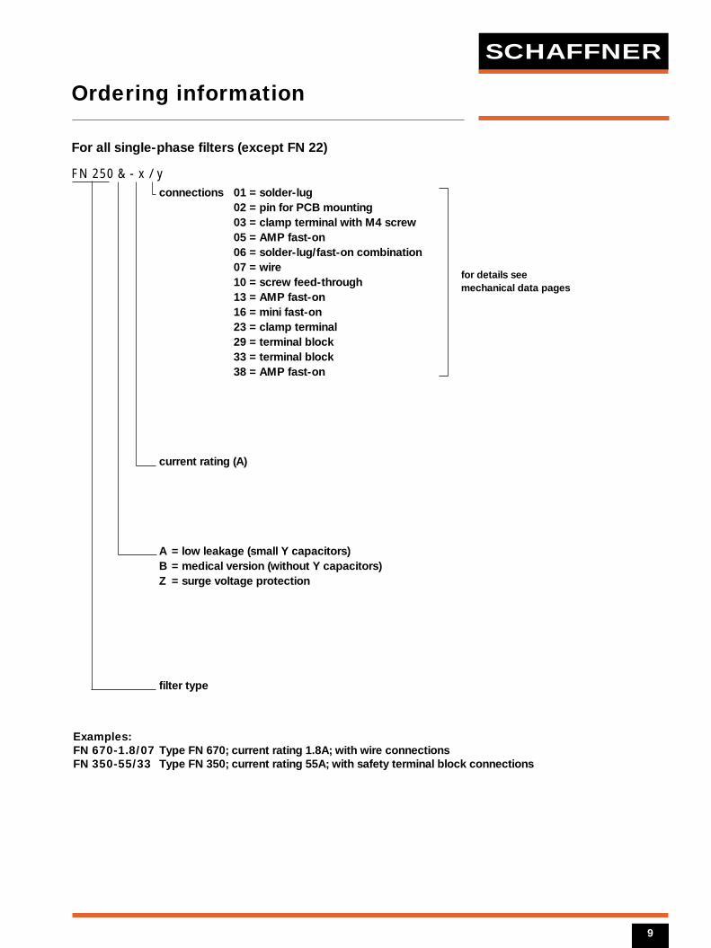
Ordering information
9
For all single-phase filters (except FN 22)
FN 250 & - x / yconnections 01 = solder-lug
02 = pin for PCB mounting03 = clamp terminal with M4 screw05 = AMP fast-on06 = solder-lug/fast-on combination07 = wire10 = screw feed-through13 = AMP fast-on16 = mini fast-on23 = clamp terminal29 = terminal block33 = terminal block38 = AMP fast-on
current rating (A)
A = low leakage (small Y capacitors)B = medical version (without Y capacitors)Z = surge voltage protection
filter type
for details seemechanical data pages
Examples:FN 670-1.8/07 Type FN 670; current rating 1.8A; with wire connections FN 350-55/33 Type FN 350; current rating 55A; with safety terminal block connections
Filter selection tableChoose the family FN xxx with the required current rating and features, and add /2 or
/3 to determine the component value.
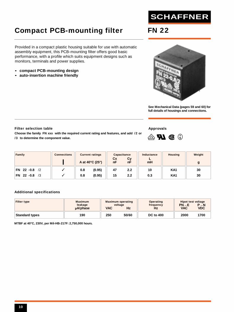
See Mechanical Data (pages 59 and 60) forfull details of housings and connections.
SCHAFFNER
47 2.2
15 2.2
Capacitance
Cx Cy nF nF
0.8 (0.95)
0.8 (0.95)
Current ratings
A at 40°C (25°)
FN 22 -0.8 /2
FN 22 -0.8 /3
Family
Connections
KA1
KA1
Housing
10
0.3
Inductance
LmH
2000 1700
Filter type
190
Maximum leakage
µA/phase
250 50/60
Maximum operatingvoltage
VAC Hz
Hipot test voltagePN→E P→N VAC VDC
Operating frequency
Hz
DC to 400
MTBF at 40°C, 230V, per Mil-HB-217F: 2,750,000 hours.
Additional specifications
Approvals
VED
FN 22
30
30
Weight
g
Provided in a compact plastic housing suitable for use with automaticassembly equipment, this PCB-mounting filter offers good basicperformance, with a profile which suits equipment designs such asmonitors, terminals and power supplies.
• compact PCB-mounting design• auto-insertion machine friendly
Compact PCB-mounting filter
Standard types
10
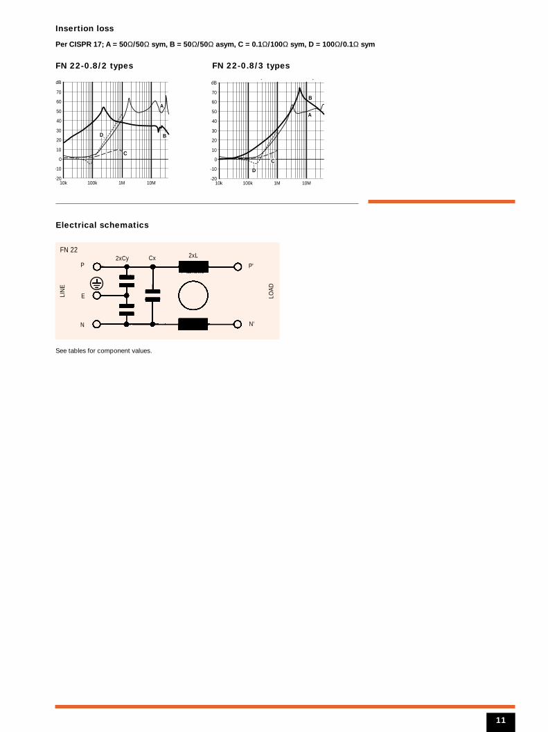
Insertion loss
Per CISPR 17; A = 50Ω/50Ω sym, B = 50Ω/50Ω asym, C = 0.1Ω/100Ω sym, D = 100Ω/0.1Ω sym
FN 22-0.8/2 types FN 22-0.8/3 types
Electrical schematics
10k 100k 1M 10M-20
-10
0
10
20
30
40
50
60
70
dB
BD
A
C
10k 100k 1M 10M-20
-10
0
10
20
30
40
50
60
70
dBy y
B
D
A
C
N
2xLCxFN 22
LIN
E
LOAD
2xCy
E
P
N'
P'
See tables for component values.
11
Filter selection tableChoose the family FN xxx with the required current rating and features, and add /??
to determine input/output (line/load) connection style. Example: FN 250-6/07 is a 6A
filter with wire connections.
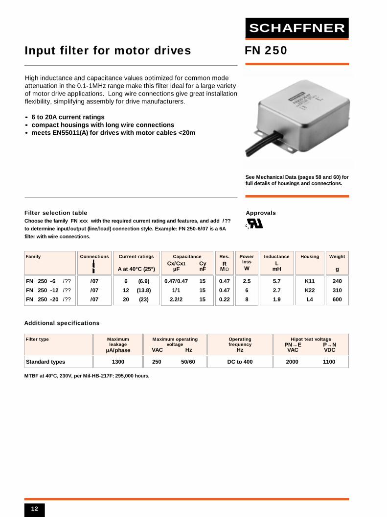
See Mechanical Data (pages 58 and 60) forfull details of housings and connections.
6 (6.9)
12 (13.8)
20 (23)
Current ratings
A at 40°C (25°)
FN 250 -6 /??
FN 250 -12 /??
FN 250 -20 /??
Family
/07
/07
/07
Connections
K11
K22
L4
Housing
2.5
6
8
Powerloss
W
5.7
2.7
1.9
Inductance
LmH
0.47/0.47 15
1/1 15
2.2/2 15
Capacitance
Cx/Cx1 Cy µF nF
2000 1100
Filter type
0.47
0.47
0.22
Res.
RMΩ
1300
Maximum leakage
µA/phase
250 50/60
Maximum operatingvoltage
VAC Hz
Hipot test voltagePN→E P→N VAC VDC
Operating frequency
Hz
DC to 400
MTBF at 40°C, 230V, per Mil-HB-217F: 295,000 hours.
Additional specifications
Approvals
FN 250
240
310
600
Weight
g
High inductance and capacitance values optimized for common modeattenuation in the 0.1-1MHz range make this filter ideal for a large varietyof motor drive applications. Long wire connections give great installationflexibility, simplifying assembly for drive manufacturers.
• 6 to 20A current ratings• compact housings with long wire connections• meets EN55011(A) for drives with motor cables <20m
Input filter for motor drives
Standard types
12
SCHAFFNER
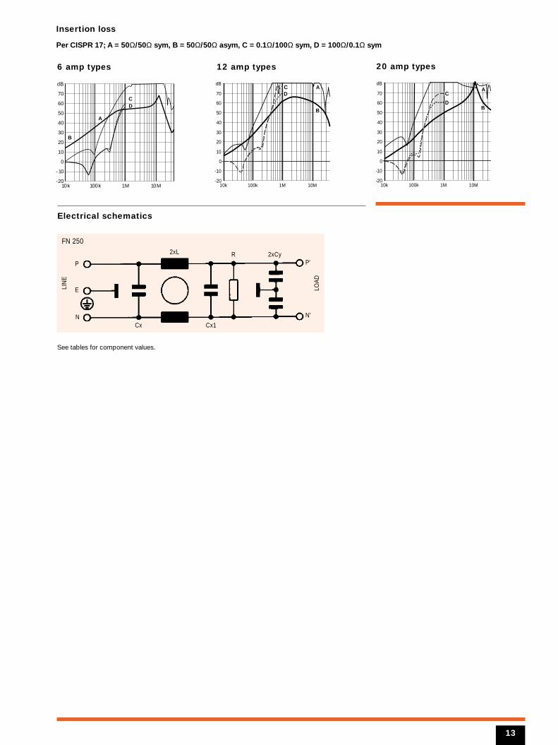
Insertion loss
Per CISPR 17; A = 50Ω/50Ω sym, B = 50Ω/50Ω asym, C = 0.1Ω/100Ω sym, D = 100Ω/0.1Ω sym
6 amp types 12 amp types 20 amp types
Electrical schematics
dB
70
60
50
40
30
20
10
0
-10
-2010k 100k 1M 10M
A
B
CD
10k 100k 1M 10M-20
-10
0
10
20
30
40
50
60
70
dB
B
DAC
10k 100k 1M 10M-20
-10
0
10
20
30
40
50
60
70
dB
BD
AC
N
2xL
Cx
R
Cx1
FN 250
LIN
E
LOAD
2xCy
E
P
N'
P'
See tables for component values.
13
Filter selection tableChoose the family FN xxx with the required current rating and features, and add /??
to determine input/output (line/load) connection style. Example: FN 332-6/01 is a 6A
filter with solder lug connections.
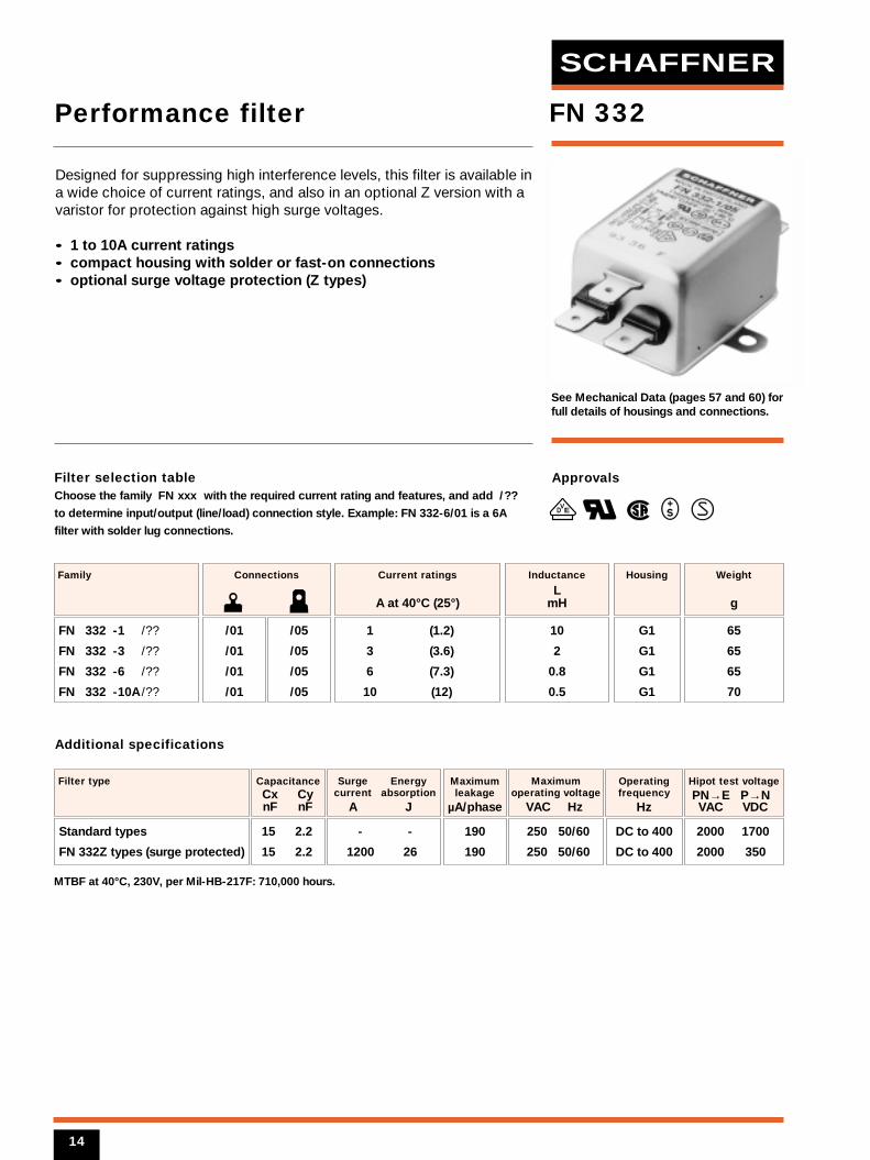
See Mechanical Data (pages 57 and 60) forfull details of housings and connections.
1 (1.2)
3 (3.6)
6 (7.3)
10 (12)
Current ratings
A at 40°C (25°)
FN 332 -1 /??
FN 332 -3 /??
FN 332 -6 /??
FN 332 -10A /??
Family
/01
/01
/01
/01
/05
/05
/05
/05
Connections
G1
G1
G1
G1
Housing
10
2
0.8
0.5
Inductance
LmH
15 2.2
15 2.2
CapacitanceCx Cy nF nF
- -
1200 26
Surge Energycurrent absorption
A J
2000 1700
2000 350
Filter type
190
190
Maximumleakage
µA/phase
250 50/60
250 50/60
Maximumoperating voltage
VAC Hz
Hipot test voltagePN→E P→N VAC VDC
Operatingfrequency
Hz
DC to 400
DC to 400
MTBF at 40°C, 230V, per Mil-HB-217F: 710,000 hours.
Additional specifications
Approvals
VED
FN 332
65
65
65
70
Weight
g
Designed for suppressing high interference levels, this filter is available ina wide choice of current ratings, and also in an optional Z version with avaristor for protection against high surge voltages.
• 1 to 10A current ratings• compact housing with solder or fast-on connections• optional surge voltage protection (Z types)
Performance filter
Standard types
FN 332Z types (surge protected)
14
SCHAFFNER
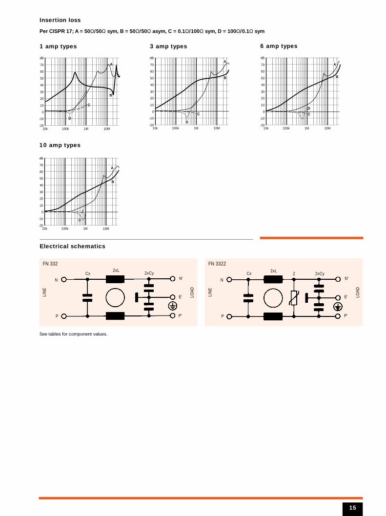
Insertion loss
Per CISPR 17; A = 50Ω/50Ω sym, B = 50Ω/50Ω asym, C = 0.1Ω/100Ω sym, D = 100Ω/0.1Ω sym
1 amp types
10 amp types
3 amp types 6 amp types
Electrical schematics
B
D
A
C
10k 100k 1M 10M-20
-10
0
10
20
30
40
50
60
70
dB
10k 100k 1M 10M-20
-10
0
10
20
30
40
50
60
70
dB
B
D
A
C
10k 100k 1M 10M-20
-10
0
10
20
30
40
50
60
70
dB
B
D
A
C
10k 100k 1M 10M-20
-10
0
10
20
30
40
50
60
70
dB
B
D
A
C
N
2xLCx
FN 332
LIN
E
LOAD
2xCy
P
N'
E'
P'
N
2xLCx Z
FN 332Z
LIN
E
LOAD
2xCy
P
N'
E'
P'
See tables for component values.
15
Filter selection tableChoose the family FN xxx with the required current rating and features, and add /??
to determine input/output (line/load) connection style. Example: FN 343-3/01 is a 3A
filter with solder lug connections.
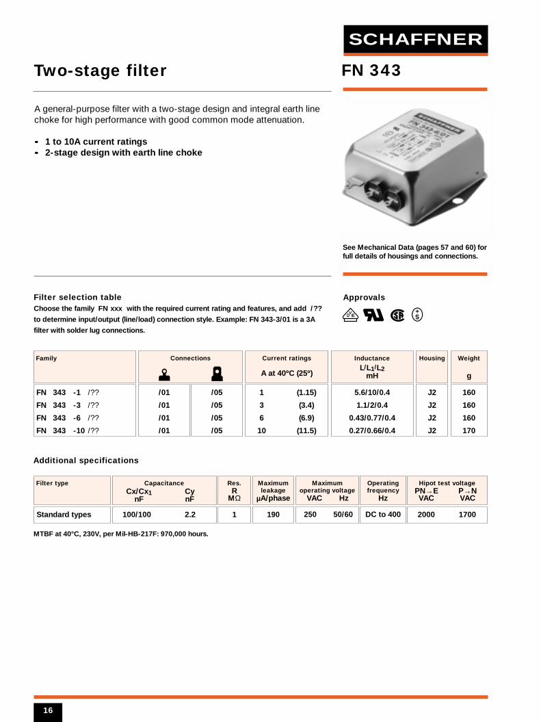
See Mechanical Data (pages 57 and 60) forfull details of housings and connections.
1 (1.15)
3 (3.4)
6 (6.9)
10 (11.5)
Current ratings
A at 40ºC (25º)
FN 343 -1 /??
FN 343 -3 /??
FN 343 -6 /??
FN 343 -10 /??
Family
/01
/01
/01
/01
/05
/05
/05
/05
Connections
J2
J2
J2
J2
Housing
5.6/10/0.4
1.1/2/0.4
0.43/0.77/0.4
0.27/0.66/0.4
Inductance
L/L1/L2mH
2000 1700
Filter type
100/100 2.2
CapacitanceCx/Cx1 Cy
nF nF
190
Maximumleakage
µA/phase
250 50/60
Maximumoperating voltage
VAC Hz
1
Res.R
MΩ
Hipot test voltagePN→E P→N VAC VAC
Operatingfrequency
Hz
DC to 400
MTBF at 40°C, 230V, per Mil-HB-217F: 970,000 hours.
Additional specifications
Approvals
FN 343
160
160
160
170
Weight
g
A general-purpose filter with a two-stage design and integral earth linechoke for high performance with good common mode attenuation.
• 1 to 10A current ratings• 2-stage design with earth line choke
Two-stage filter
Standard types
16
VED
SCHAFFNER
1 amp types
10 amp types
3 amp types
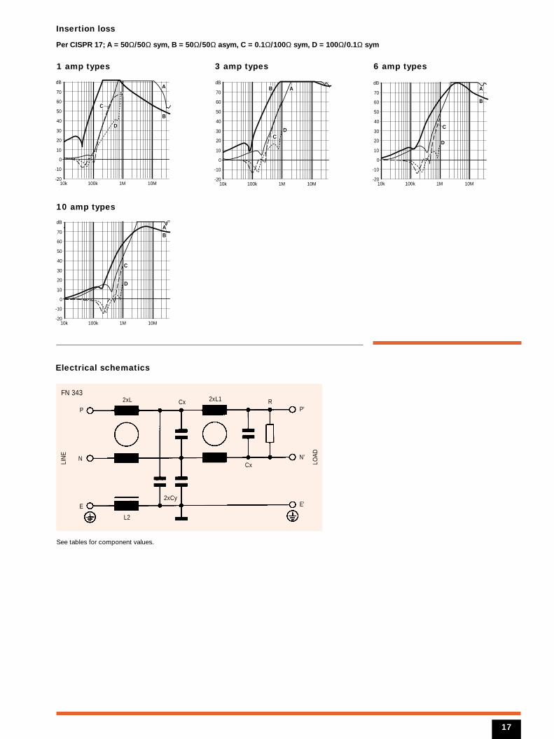
Electrical schematics
10k 100k 1M 10M-20
-10
0
10
20
30
40
50
60
70
dB
B
D
A
C
10k 100k 1M 10M-20
-10
0
10
20
30
40
50
60
70
dBB
D
A
C
6 amp types
10k 100k 1M 10M-20
-10
0
10
20
30
40
50
60
70
dB
B
D
A
C
10k 100k 1M 10M-20
-10
0
10
20
30
40
50
60
70
dB
B
D
A
C
N
2xL Cx
Cx
RFN 343
LIN
E
LOAD
2xL1
L2
2xCyE
P
N'
E'
P'
See tables for component values.
17
Insertion loss
Per CISPR 17; A = 50Ω/50Ω sym, B = 50Ω/50Ω asym, C = 0.1Ω/100Ω sym, D = 100Ω/0.1Ω sym
Filter selection tableChoose the family FN xxx with the required current rating and features, and add /??
to determine input/output (line/load) connection style. Example: FN 346-10/06 is a 10A
filter with fast-on connections.
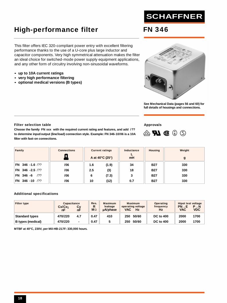
See Mechanical Data (pages 56 and 60) forfull details of housings and connections.
1.6 (1.9)
2.5 (3)
6 (7.3)
10 (12)
Current ratings
A at 40°C (25°)
FN 346 -1.6 /??
FN 346 -2.5 /??
FN 346 -6 /??
FN 346 -10 /??
Family
/06
/06
/06
/06
Connections
B27
B27
B27
B27
Housing
34
18
3
0.7
Inductance
LmH
470/220 4.7
470/220 -
CapacitanceCx/Cx1 Cy
nF nF
2000 1700
2000 1700
Filter type
0.47
0.47
Res.R
MΩ
410
5
Maximumleakage
µA/phase
250 50/60
250 50/60
Maximumoperating voltage
VAC Hz
Hipot test voltagePN→E P→N VAC VDC
Operatingfrequency
Hz
DC to 400
DC to 400
MTBF at 40°C, 230V, per Mil-HB-217F: 330,000 hours.
Additional specifications
Approvals
VED
FN 346
330
330
330
330
Weight
g
This filter offers IEC 320-compliant power entry with excellent filteringperformance thanks to the use of a U-core plus large inductor andcapacitor components. Very high symmetrical attenuation makes the filteran ideal choice for switched-mode power supply equipment applications,and any other form of circuitry involving non-sinusoidal waveforms.
• up to 10A current ratings• very high performance filtering• optional medical versions (B types)
High-performance filter
Standard types
B types (medical)
18
SCHAFFNER
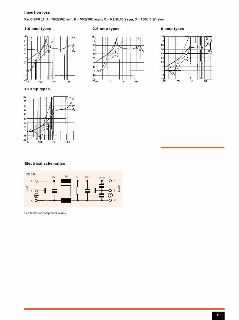
Insertion loss
Per CISPR 17; A = 50Ω/50Ω sym, B = 50Ω/50Ω asym, C = 0.1Ω/100Ω sym, D = 100Ω/0.1Ω sym
1.6 amp types
10 amp types
2.5 amp types
Electrical schematics
6 amp types
N
2xLCx RFN 346
LIN
E
LOAD
2xCy
E
P
N'
E'
P'
See tables for component values.
19
Cx1
Filter selection tableChoose the family FN xxx with the required current rating and features, and add /??
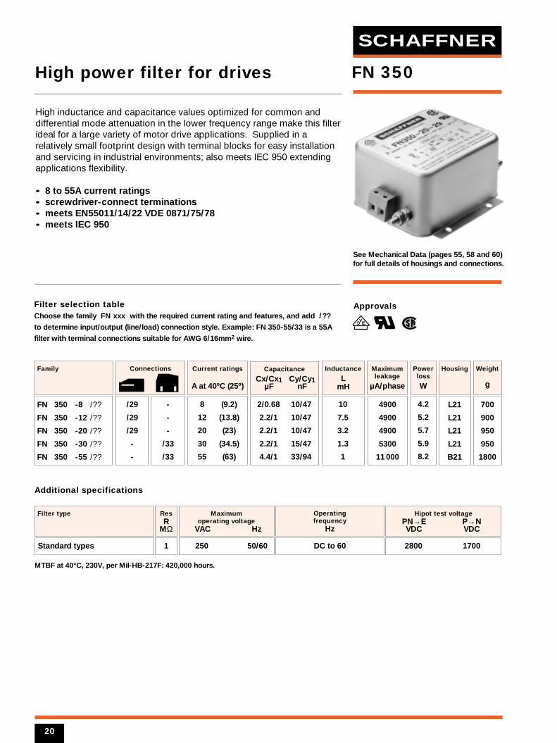
to determine input/output (line/load) connection style. Example: FN 350-55/33 is a 55A
filter with terminal connections suitable for AWG 6/16mm2 wire.
See Mechanical Data (pages 55, 58 and 60)for full details of housings and connections.
8 (9.2)
12 (13.8)
20 (23)
30 (34.5)
55 (63)
Current ratings
A at 40ºC (25º)
FN 350 -8 /??
FN 350 -12 /??
FN 350 -20 /??
FN 350 -30 /??
FN 350 -55 /??
Family
/29
/29
/29
-
-
-
-
-
/33
/33
Connections
L21
L21
L21
L21
B21
Housing
4.2
5.2
5.7
5.9
8.2
Powerloss
W
10
7.5
3.2
1.3
1
Inductance
LmH
2800 1700
Filter type
2/0.68 10/47
2.2/1 10/47
2.2/1 10/47
2.2/1 15/47
4.4/1 33/94
Capacitance
Cx/Cx1 Cy/Cy1µF nF
4900
4900
4900
5300
11 000
Maximumleakage
µA/phase
250 50/60
Maximum operating voltage
VAC Hz
1
ResR
MΩ
Hipot test voltagePN→E P→N VDC VDC
Operating frequency
Hz
DC to 60
MTBF at 40°C, 230V, per Mil-HB-217F: 420,000 hours.
Additional specifications
Approvals
FN 350
700
900
950
950
1800
Weight
g
High inductance and capacitance values optimized for common anddifferential mode attenuation in the lower frequency range make this filterideal for a large variety of motor drive applications. Supplied in arelatively small footprint design with terminal blocks for easy installationand servicing in industrial environments; also meets IEC 950 extendingapplications flexibility.
• 8 to 55A current ratings• screwdriver-connect terminations• meets EN55011/14/22 VDE 0871/75/78• meets IEC 950
High power filter for drives
Standard types
VED
20
SCHAFFNER
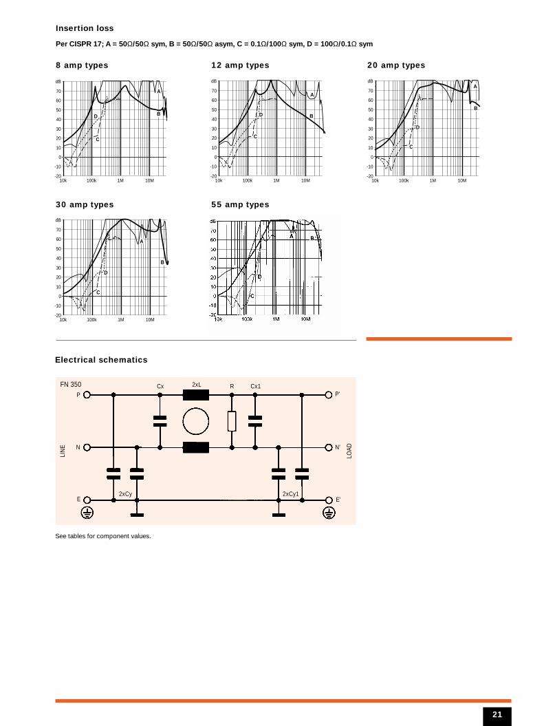
Insertion loss
Per CISPR 17; A = 50Ω/50Ω sym, B = 50Ω/50Ω asym, C = 0.1Ω/100Ω sym, D = 100Ω/0.1Ω sym
8 amp types 12 amp types
Electrical schematics
10k 100k 1M 10M-20
-10
0
10
20
30
40
50
60
70
dB
BD
A
C
10k 100k 1M 10M-20
-10
0
10
20
30
40
50
60
70
dB
BD
A
C
30 amp types 55 amp types
10k 100k 1M 10M-20
-10
0
10
20
30
40
50
60
70
dB
B
D
A
C
N
2xLCx
2xCy 2xCy1
FN 350
LIN
E
LOAD
Cx1R
E
P
N'
E'
P'
See tables for component values.
20 amp types
10k 100k 1M 10M-20
-10
0
10
20
30
40
50
60
70
dB
B
D
A
C
21
Filter selection tableChoose the family FN xxx with the required current rating and features, and add /??
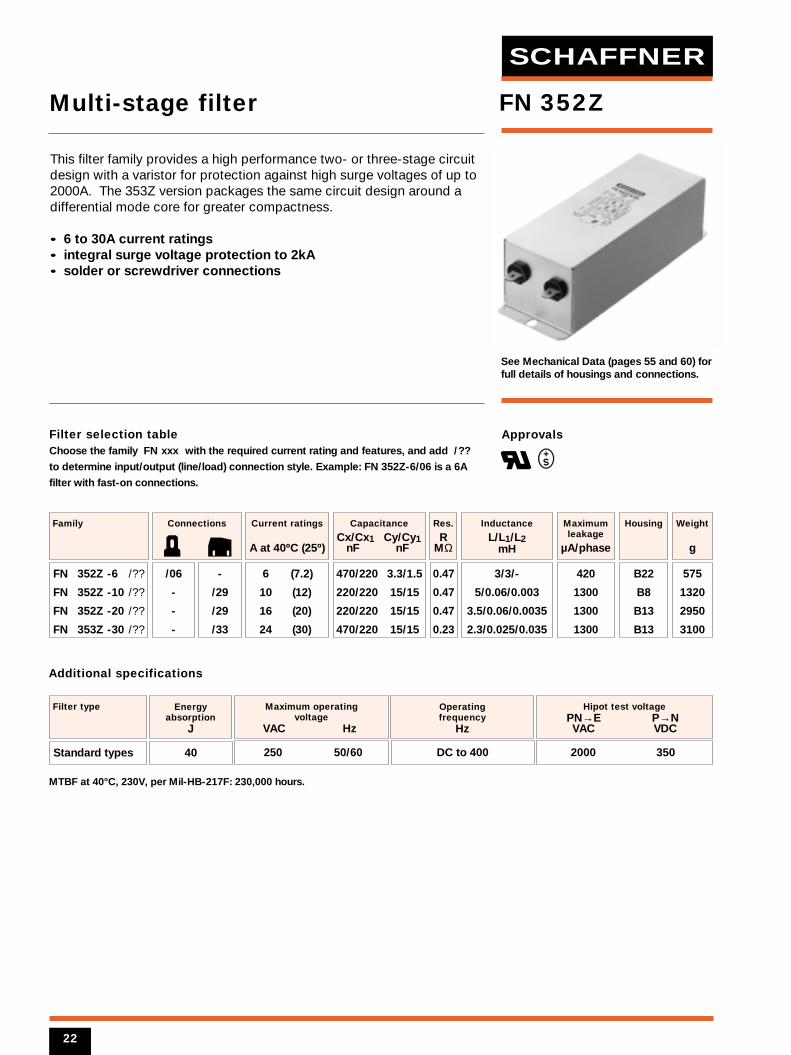
to determine input/output (line/load) connection style. Example: FN 352Z-6/06 is a 6A
filter with fast-on connections.
See Mechanical Data (pages 55 and 60) forfull details of housings and connections.
6 (7.2)
10 (12)
16 (20)
24 (30)
Current ratings
A at 40ºC (25º)
FN 352Z -6 /??
FN 352Z -10 /??
FN 352Z -20 /??
FN 353Z -30 /??
Family
/06
-
-
-
-
/29
/29
/33
Connections
3/3/-
5/0.06/0.003
3.5/0.06/0.0035
2.3/0.025/0.035
Inductance
L/L1/L2mH
2000 350
Filter type
470/220 3.3/1.5
220/220 15/15
220/220 15/15
470/220 15/15
Capacitance
Cx/Cx1 Cy/Cy1nF nF
420
1300
1300
1300
Maximumleakage
µA/phase
B22
B8
B13
B13
Housing
250 50/60
Maximum operating voltage
VAC Hz
40
Energyabsorption
J
0.47
0.47
0.47
0.23
Res.
RMΩ
Hipot test voltagePN→E P→N VAC VDC
Operating frequency
Hz
DC to 400
MTBF at 40°C, 230V, per Mil-HB-217F: 230,000 hours.
Additional specifications
Approvals
FN 352Z
575
1320
2950
3100
Weight
g
This filter family provides a high performance two- or three-stage circuitdesign with a varistor for protection against high surge voltages of up to2000A. The 353Z version packages the same circuit design around adifferential mode core for greater compactness.
• 6 to 30A current ratings• integral surge voltage protection to 2kA• solder or screwdriver connections
Multi-stage filter
Standard types
22
SCHAFFNER
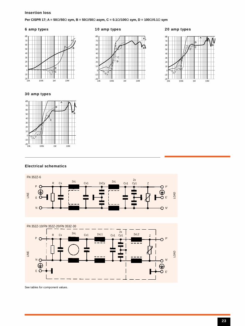
Insertion loss
Per CISPR 17; A = 50Ω/50Ω sym, B = 50Ω/50Ω asym, C = 0.1Ω/100Ω sym, D = 100Ω/0.1Ω sym
6 amp types 10 amp types
Electrical schematics
10k 100k 1M 10M-20
-10
0
10
20
30
40
50
60
70
dB
B
D
A
C
10k 100k 1M 10M-20
-10
0
10
20
30
40
50
60
70
dB
B
D
A
C
20 amp types
10k 100k 1M 10M-20
-10
0
10
20
30
40
50
60
70
dB
BD
A
C
30 amp types
10k 100k 1M 10M-20
-10
0
10
20
30
40
50
60
70
dB
B
D
A
C
N
2xLR Cx Cx1 2xCy
FN 352Z-6
LIN
E
LOAD
2xLCx1 Z
2xCy1
E
P
N'
E'
P'
N
2xLR Cx Cx1 Cx1
FN 352Z-10/FN 352Z-20/FN 353Z-30
LIN
E
LOAD
2xL1 2xL2 Z2x
Cy1
E
P
N'
E'
P'
See tables for component values.
23
Filter selection tableChoose the family FN xxx with the required current rating and features, and add /??
to determine input/output (line/load) connection style. Example: FN 357-10/29 is a 10A
filter with terminal connections suitable for AWG 10/6mm2 wire.
See Mechanical Data (pages 55 and 60) forfull details of housings and connections.
6 (6.9)
10 (11.5)
16 (18.4)
Current ratings
A at 40ºC (25º)
FN 357 -6 /??
FN 357 -10 /??
FN 357 -16 /??
Family
/29
/29
/29
Connections
B7
B7
B11
Housing
5.5
6.2
8.4
Powerloss
W
3.5/0.75
2.8/0.45
2.3/0.4
Inductance
L/L1mH
2800 1100
Filter type
1.5/2.2 22/-
2.2/2.2 22/33
3/3 47/47
Capacitance
Cx/Cx1 Cy/Cy1µF nF
3800
4800
8100
Maximumleakage
µA/phase
250 50/60
Maximum operating voltage
VAC Hz
0.1
0.1
0.075
Res.
RMΩ
Hipot test voltagePN→E P→N VDC VDC
Operating frequency
Hz
DC to 60
MTBF at 40°C, 230V, per Mil-HB-217F: 250,000 hours.
Additional specifications
Approvals
FN 357
1450
1500
3000
Weight
g
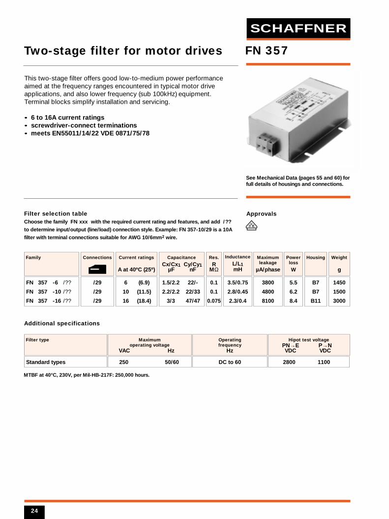
This two-stage filter offers good low-to-medium power performanceaimed at the frequency ranges encountered in typical motor driveapplications, and also lower frequency (sub 100kHz) equipment.Terminal blocks simplify installation and servicing.
• 6 to 16A current ratings• screwdriver-connect terminations• meets EN55011/14/22 VDE 0871/75/78
Two-stage filter for motor drives
Standard types
VED
24
SCHAFFNER
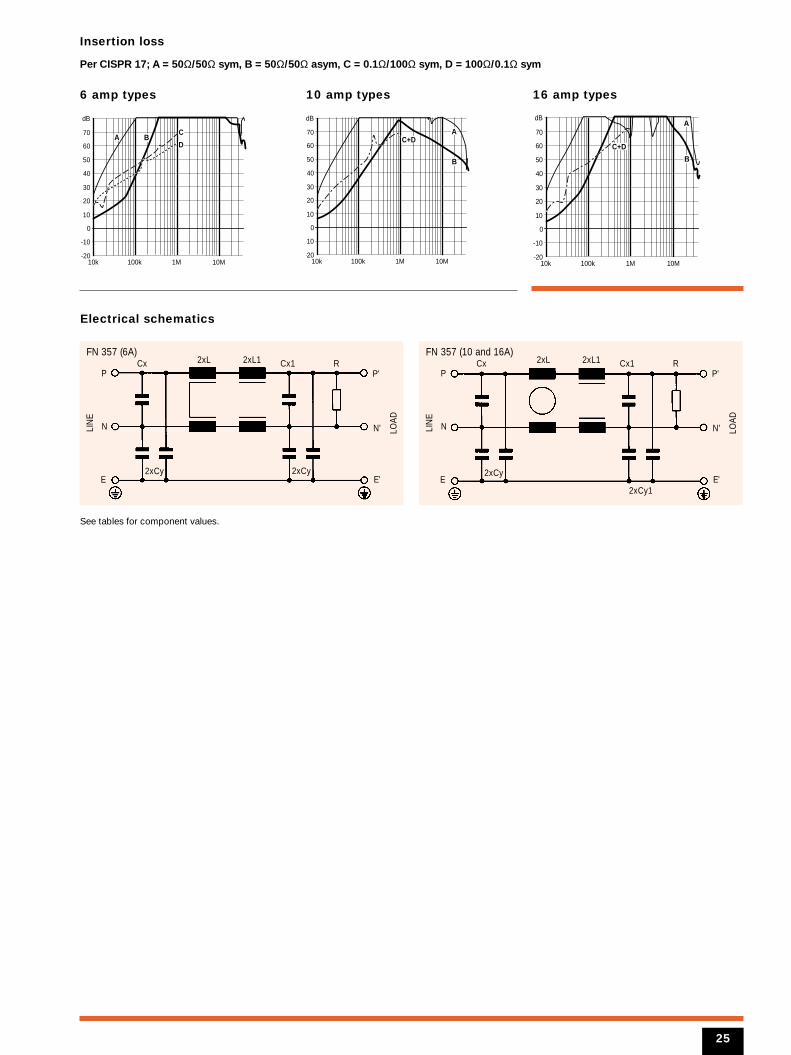
Insertion loss
Per CISPR 17; A = 50Ω/50Ω sym, B = 50Ω/50Ω asym, C = 0.1Ω/100Ω sym, D = 100Ω/0.1Ω sym
6 amp types 10 amp types
Electrical schematics
10k 100k 1M 10M-20
-10
0
10
20
30
40
50
60
70
dB
BD
AC
10k 100k 1M 10M-20
-10
0
10
20
30
40
50
60
70
dB
B
AC+D
N
2xL 2xL1Cx Cx1 RFN 357 (6A)
LIN
E
LOAD
2xCy2xCyE
P
N'
E'
P'
See tables for component values.
N
2xL 2xL1Cx Cx1 RFN 357 (10 and 16A)
LIN
E
LOAD
2xCy1
2xCyE
P
N'
E'
P'
16 amp types
10k 100k 1M 10M-20
-10
0
10
20
30
40
50
60
70
dB
B
A
C+D
25
Filter selection tableChoose the family FN xxx with the required current rating and features, and add /??
to determine input/output (line/load) connection style. Example: FN 401-1.5/02 is a 1.5A
filter with pin connections.
See Mechanical Data (pages 59 and 60) forfull details of housings and connections.
0.8 (0.95)
1.5 (1.8)
Current ratings
A at 40ºC (25º)
FN 401 -0.8 /??
FN 401 -1.5 /??
Family
/02
/02
Connections
20
20
Inductance
LmH
2000 1100
Filter type
68 15 2.2
100 – 2.2
Capacitance
Cx Cx1 CynF nF nF
KA2
KA3
Housing
250 50/60
Maximum operatingvoltage
VAC Hz
190
Maximum leakage
µA/phase
-
1
Res.
RMΩ
Hipot test voltagePN→E P→N VAC VDC
Operating frequency
Hz
DC to 400
MTBF at 40°C, 230V, per Mil-HB-217F: 1,000,000 hours.
Additional specifications
Approvals
FN 401
30
90
Weight
g
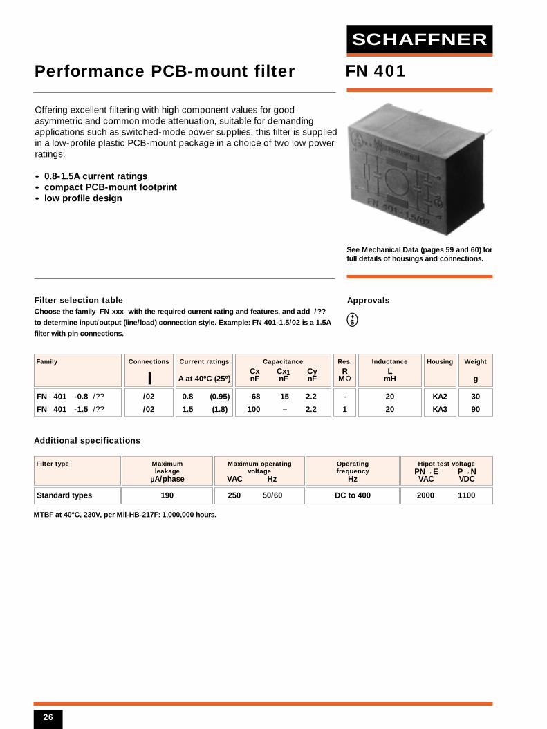
Offering excellent filtering with high component values for goodasymmetric and common mode attenuation, suitable for demandingapplications such as switched-mode power supplies, this filter is suppliedin a low-profile plastic PCB-mount package in a choice of two low powerratings.
• 0.8-1.5A current ratings• compact PCB-mount footprint• low profile design
Performance PCB-mount filter
Standard types
26
SCHAFFNER
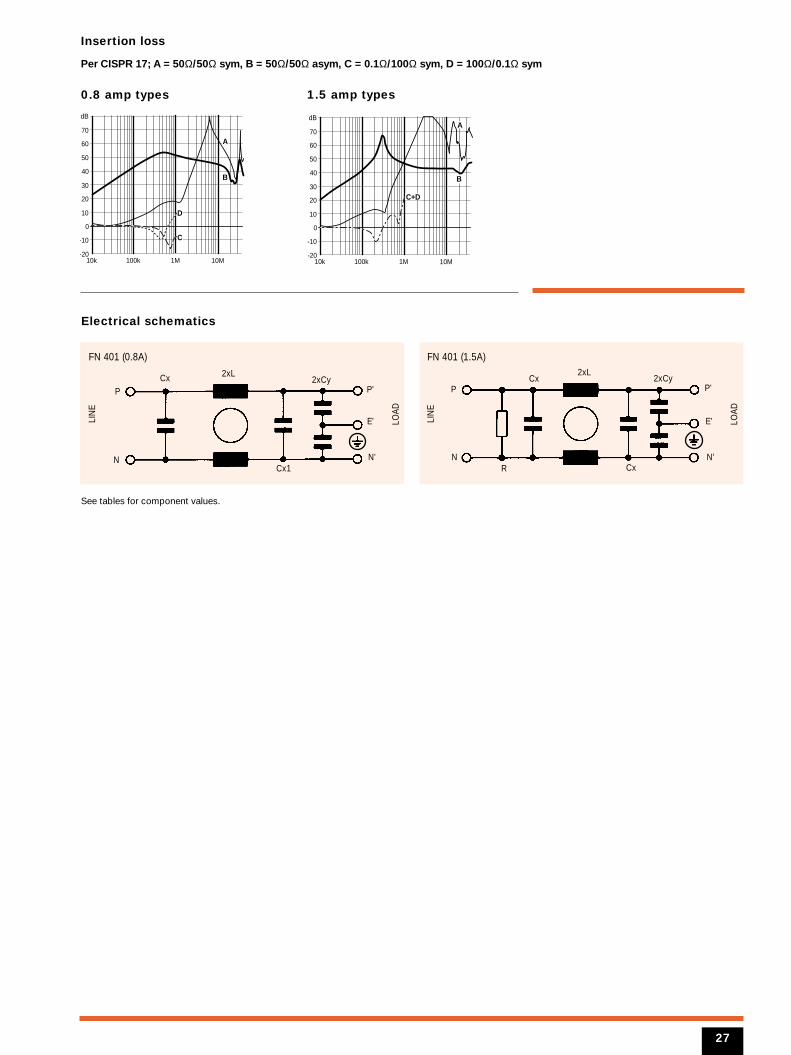
Insertion loss
Per CISPR 17; A = 50Ω/50Ω sym, B = 50Ω/50Ω asym, C = 0.1Ω/100Ω sym, D = 100Ω/0.1Ω sym
0.8 amp types 1.5 amp types
Electrical schematics
10k 100k 1M 10M-20
-10
0
10
20
30
40
50
60
70
dBy y
B
D
A
C
10k 100k 1M 10M-20
-10
0
10
20
30
40
50
60
70
dB
B
A
C+D
N
2xLCx
R Cx
FN 401 (1.5A)
LIN
E
LOAD
2xCyP
N'
E'
P'
N
2xLCx
Cx1
FN 401 (0.8A)
LIN
E
LOAD
2xCyP
N'
E'
P'
See tables for component values.
27
Filter selection tableChoose the family FN xxx with the required current rating and features, and add /??
to determine input/output (line/load) connection style. Example: FN 402-4/16 is a 4A
filter with mini fast-on connections.
See Mechanical Data (pages 59 and 60) forfull details of housings and connections.
0.5 (0.6)
1 (1.2)
1.6 (1.9)
2.5 (3.0)
4 (4.7)
6.5 (7.5)
Current ratings
A at 40ºC (25º)
FN 402 -0.5 /??
FN 402 -1 /??
FN 402 -1.6 /??
FN 402 -2.5 /??
FN 402 -4 /??
FN 402 -6.5 /??
Family
/02
/02
/02
/02
/02
/02
/07*
/07*
/07*
/07*
/07*
/07*
/16
/16
/16
/16
/16
/16
/38
/38
/38
/38
/38
/38
Connections
KA/KB
KA/KB
KA/KB
KA/KB
KA/KB
KA/KB
Housing
40
10
6
2
1
1
Inductance
LmH
2000 1700
2500 1700
Filter type
* /07 outputs add 5g to weight
100 2.2
100 -
CapacitanceCx Cy nF nF
190
2
Maximumleakage
µA/phase
250 50/60
250 50/60
Maximumoperating voltage
VAC Hz
1
1
Res.R
MΩ
Hipot test voltagePN→E P→N VAC VDC
Operatingfrequency
Hz
DC to 400
DC to 400
MTBF at 40°C, 230V, per Mil-HB-217F: 1,900,000 hours. (standard types); 1,200,000 hours (B types)
Additional specifications
Approvals
FN 402
40
40
40
40
40
40
Weight
g
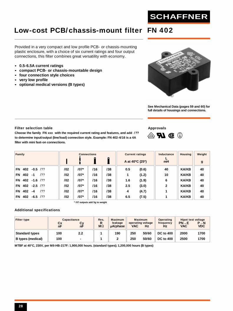
Provided in a very compact and low profile PCB- or chassis-mountingplastic enclosure, with a choice of six current ratings and four outputconnections, this filter combines great versatility with economy.
• 0.5-6.5A current ratings• compact PCB- or chassis-mountable design• four connection style choices• very low profile• optional medical versions (B types)
Low-cost PCB/chassis-mount filter
Standard types
B types (medical)
28
VED
SCHAFFNER
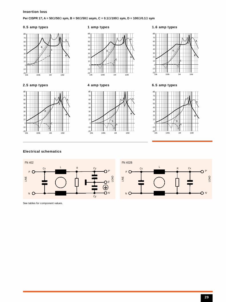
Insertion loss
Per CISPR 17; A = 50Ω/50Ω sym, B = 50Ω/50Ω asym, C = 0.1Ω/100Ω sym, D = 100Ω/0.1Ω sym
0.5 amp types
2.5 amp types
1 amp types
Electrical schematics
10k 100k 1M 10M-20
-10
0
10
20
30
40
50
60
70
dB
B
DC
A
10k 100k 1M 10M-20
-10
0
10
20
30
40
50
60
70
dB
B
D
C
A
1.6 amp types
10k 100k 1M 10M-20
-10
0
10
20
30
40
50
60
70
dB
B
D
C
A
6.5 amp types
10k 100k 1M 10M-20
-10
0
10
20
30
40
50
60
70
dB
B
DC
A
4 amp types
10k 100k 1M 10M-20
-10
0
10
20
30
40
50
60
70
dB
B
DC
A
10k 100k 1M 10M-20
-10
0
10
20
30
40
50
60
70
dB
B
D
C
A
See tables for component values.
29
N
L RCx
FN 402
LIN
E
LOAD
Cy
Cy
P
N'
E'
P'
N
LCx R
FN 402B
LIN
E
LOAD
CxP
N'
P'
Filter selection tableChoose the family FN xxx with the required current rating and features, and add /??
to determine input/output (line/load) connection style. Example: FN 405-6/02 is a 6A
filter with pin connections.
See Mechanical Data (pages 59 and 60) forfull details of housings and connections.
0.5 (0.6)
1 (1.2)
3 (3.6)
6 (6.9)
Current ratings
A at 40°C (25°)
FN 405 -0.5 /??
FN 405 -1 /??
FN 405 -3 /??
FN 405 -6 /??
Family
/02
/02
/02
/02
Connections
KA4
KA4
KA4
KA4
Housing
24
10
2
0.8
Inductance
LmH
15 2.2
CapacitanceCx Cy nF nF
2000 1100
Filter type
190
Maximumleakage
µA/phase
250 50/60
Maximum operatingvoltage
VAC Hz
Hipot test voltagePN→E P→N VAC VDC
Operating frequency
Hz
DC to 400
MTBF at 40°C, 230V, per Mil-HB-217F: 1,600,000 hours.
Additional specifications
Approvals
VED
FN 405
40
40
40
40
Weight
g
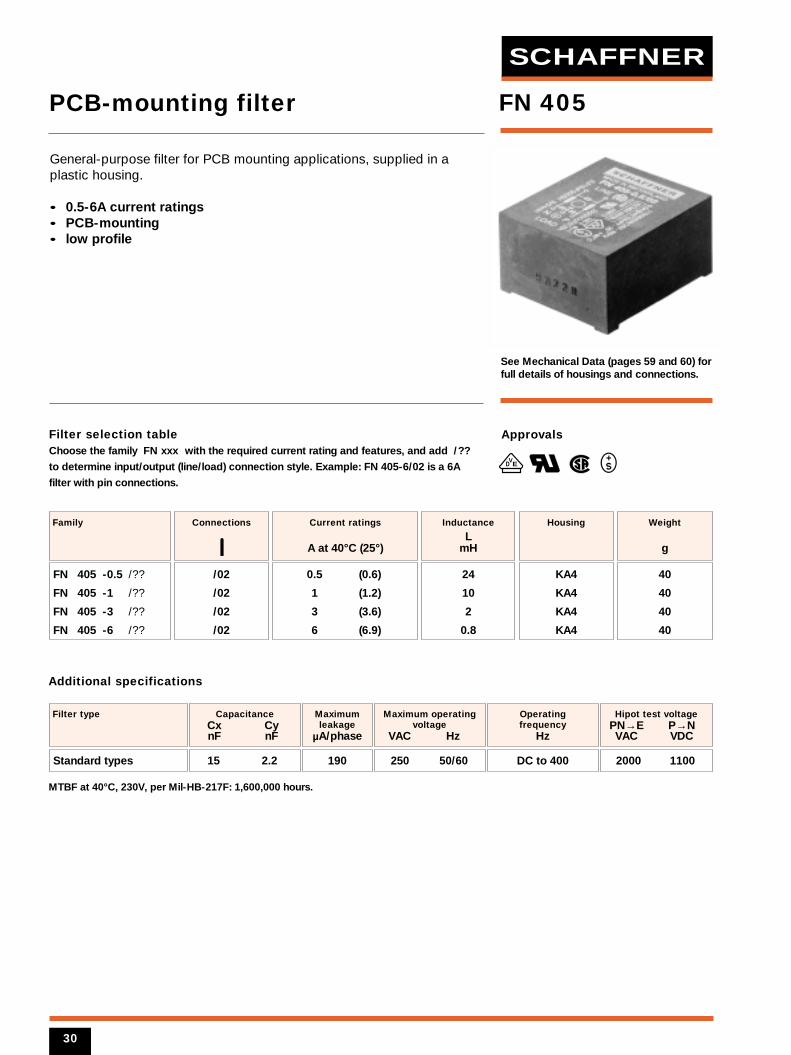
General-purpose filter for PCB mounting applications, supplied in aplastic housing.
• 0.5-6A current ratings• PCB-mounting• low profile
PCB-mounting filter
Standard types
30
SCHAFFNER
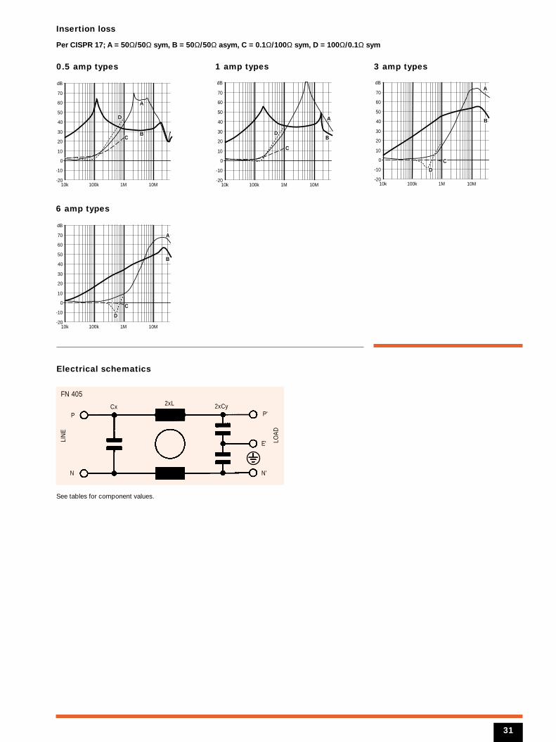
Insertion loss
Per CISPR 17; A = 50Ω/50Ω sym, B = 50Ω/50Ω asym, C = 0.1Ω/100Ω sym, D = 100Ω/0.1Ω sym
0.5 amp types
6 amp types
1 amp types
Electrical schematics
10k 100k 1M 10M-20
-10
0
10
20
30
40
50
60
70
dB
B
D
A
C
10k 100k 1M 10M-20
-10
0
10
20
30
40
50
60
70
dB
BD
A
C
3 amp types
10k 100k 1M 10M-20
-10
0
10
20
30
40
50
60
70
dB
B
D
A
C
10k 100k 1M 10M-20
-10
0
10
20
30
40
50
60
70
dB
B
D
A
C
N
2xLCx
FN 405
LIN
E
LOAD
2xCyP
N'
E'
P'
See tables for component values.
31
Filter selection tableChoose the family FN xxx with the required current rating and features, and add /??
to determine input/output (line/load) connection style. Example: FN 406-6/02 is a 6A
filter with pin connections.
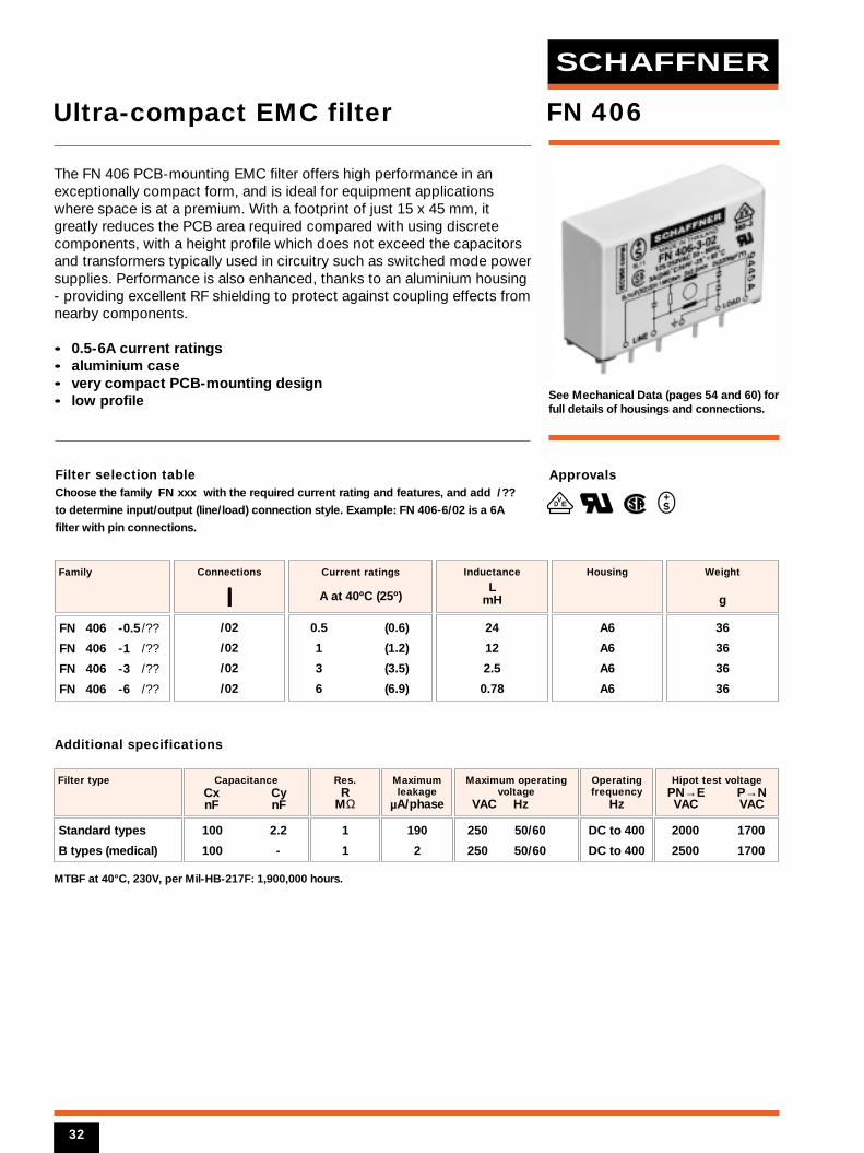
See Mechanical Data (pages 54 and 60) forfull details of housings and connections.
0.5 (0.6)
1 (1.2)
3 (3.5)
6 (6.9)
Current ratings
A at 40ºC (25º)
FN 406 -0.5 /??
FN 406 -1 /??
FN 406 -3 /??
FN 406 -6 /??
Family
/02
/02
/02
/02
Connections
A6
A6
A6
A6
Housing
24
12
2.5
0.78
Inductance
LmH
2000 1700
2500 1700
Filter type
100 2.2
100 -
CapacitanceCx Cy nF nF
190
2
Maximumleakage
µA/phase
250 50/60
250 50/60
Maximum operatingvoltage
VAC Hz
1
1
Res.R
MΩ
Hipot test voltagePN→E P→N VAC VAC
Operatingfrequency
Hz
DC to 400
DC to 400
MTBF at 40°C, 230V, per Mil-HB-217F: 1,900,000 hours.
Additional specifications
Approvals
FN 406
36
36
36
36
Weight
g
The FN 406 PCB-mounting EMC filter offers high performance in anexceptionally compact form, and is ideal for equipment applicationswhere space is at a premium. With a footprint of just 15 x 45 mm, itgreatly reduces the PCB area required compared with using discretecomponents, with a height profile which does not exceed the capacitorsand transformers typically used in circuitry such as switched mode powersupplies. Performance is also enhanced, thanks to an aluminium housing- providing excellent RF shielding to protect against coupling effects fromnearby components.
• 0.5-6A current ratings• aluminium case• very compact PCB-mounting design• low profile
Ultra-compact EMC filter
Standard types
B types (medical)
VED
32
SCHAFFNER
Insertion loss
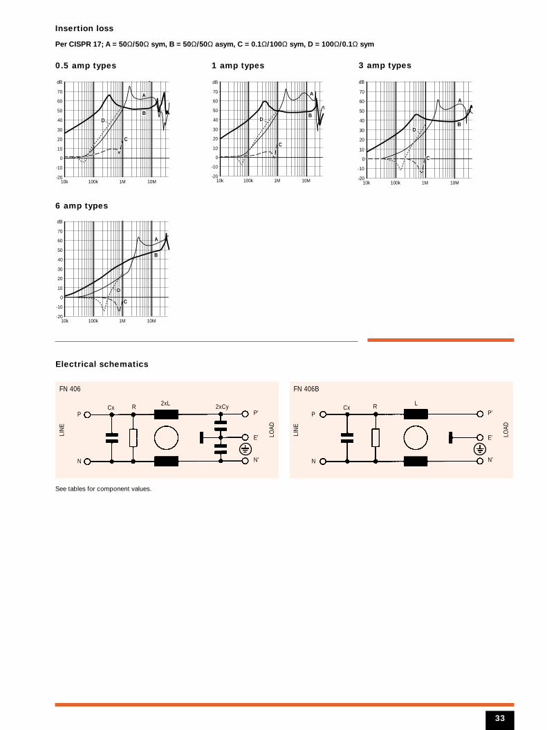
Per CISPR 17; A = 50Ω/50Ω sym, B = 50Ω/50Ω asym, C = 0.1Ω/100Ω sym, D = 100Ω/0.1Ω sym
0.5 amp types 3 amp types1 amp types
Electrical schematics
10k 100k 1M 10M-20
-10
0
10
20
30
40
50
60
70
dB
BD
C
A
10k 100k 1M 10M-20
-10
0
10
20
30
40
50
60
70
dB
BD
C
A
6 amp types
10k 100k 1M 10M-20
-10
0
10
20
30
40
50
60
70
dB
B
D
C
A
10k 100k 1M 10M-20
-10
0
10
20
30
40
50
60
70
dB
BD
C
A
See tables for component values.
33
N
2xLCx R
FN 406
LIN
E
LOAD
2xCyP
N'
E'
P'
N
LCx R
FN 406B
LIN
E
LOAD
P
N'
E'
P'
Filter selection tableChoose the family FN xxx with the required current rating and features, and add /??
to determine input/output (line/load) connection style. Example: FN 410-6/02 is a 6A
filter with pin connections.
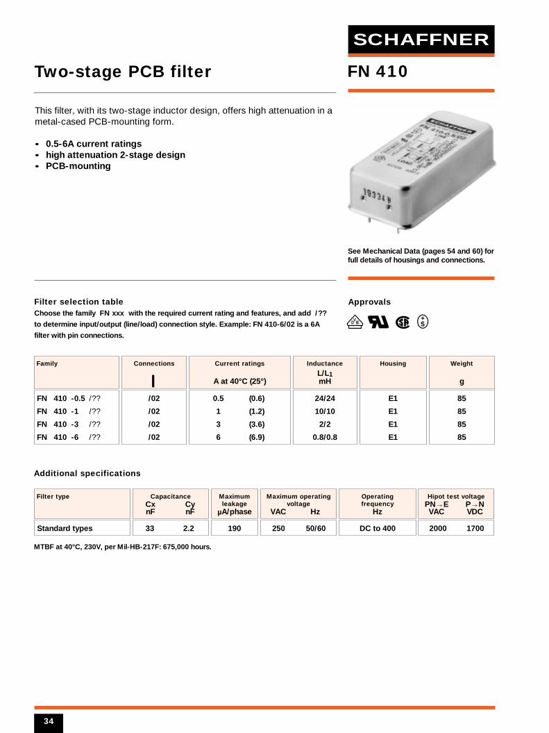
See Mechanical Data (pages 54 and 60) forfull details of housings and connections.
0.5 (0.6)
1 (1.2)
3 (3.6)
6 (6.9)
Current ratings
A at 40°C (25°)
FN 410 -0.5 /??
FN 410 -1 /??
FN 410 -3 /??
FN 410 -6 /??
Family
/02
/02
/02
/02
Connections
E1
E1
E1
E1
Housing
24/24
10/10
2/2
0.8/0.8
Inductance
L/L1mH
33 2.2
CapacitanceCx Cy nF nF
2000 1700
Filter type
190
Maximumleakage
µA/phase
250 50/60
Maximum operatingvoltage
VAC Hz
Hipot test voltagePN→E P→N VAC VDC
Operating frequency
Hz
DC to 400
MTBF at 40°C, 230V, per Mil-HB-217F: 675,000 hours.
Additional specifications
Approvals
VED
FN 410
85
85
85
85
Weight
g
This filter, with its two-stage inductor design, offers high attenuation in ametal-cased PCB-mounting form.
• 0.5-6A current ratings• high attenuation 2-stage design• PCB-mounting
Two-stage PCB filter
Standard types
34
SCHAFFNER
Insertion loss
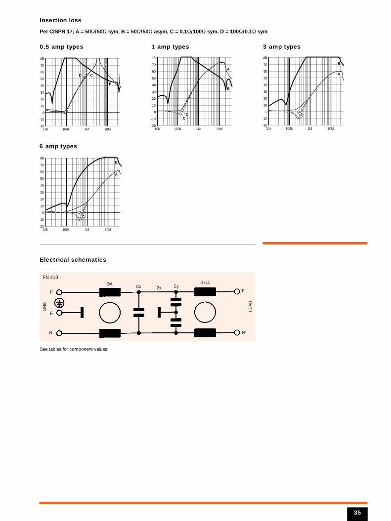
Per CISPR 17; A = 50Ω/50Ω sym, B = 50Ω/50Ω asym, C = 0.1Ω/100Ω sym, D = 100Ω/0.1Ω sym
0.5 amp types
6 amp types
1 amp types
Electrical schematics
10k 100k 1M 10M-20
-10
0
10
20
30
40
50
60
70
dB
B
D
A
C
10k 100k 1M 10M-20
-10
0
10
20
30
40
50
60
70
dB
B
D
A
C
3 amp types
10k 100k 1M 10M-20
-10
0
10
20
30
40
50
60
70
dB
B
D
A
C
10k 100k 1M 10M-20
-10
0
10
20
30
40
50
60
70
dBB
D
A
C
N
2xLCx
FN 410
LIN
E
LOAD
Cy2x2xL1
E
P
N'
P'
See tables for component values.
35
Filter selection tableChoose the family FN xxx with the required current rating and features, and add /??
to determine input/output (line/load) connection style. Example: FN 422-4/13 is a 4A
filter with mini fast-on connections.
See Mechanical Data (pages 54 and 60) forfull details of housings and connections.
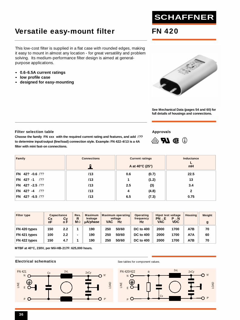
0.6 (0.7)
1 (1.2)
2.5 (3)
4 (4.8)
6.5 (7.3)
Current ratings
A at 40°C (25°)
FN 42? -0.6 /??
FN 42? -1 /??
FN 42? -2.5 /??
FN 42? -4 /??
FN 42? -6.5 /??
Family
/13
/13
/13
/13
/13
Connections
22.5
13
3.4
2
0.75
Inductance
LmH
150 2.2
100 2.2
150 4.7
CapacitanceCx Cy nF n F
2000 1700
2000 1700
2000 1700
Filter type
1
-
1
Res.R
MΩ
190
190
190
Maximumleakage
µA/phase
70
60
70
Weight
g
A7B
A7A
A7B
Housing
250 50/60
250 50/60
250 50/60
Maximum operatingvoltage
VAC Hz
Hipot test voltagePN→E P→N VAC VDC
Operatingfrequency
Hz
DC to 400
DC to 400
DC to 400
MTBF at 40°C, 230V, per Mil-HB-217F: 625,000 hours.
Approvals
VED
FN 420
This low-cost filter is supplied in a flat case with rounded edges, makingit easy to mount in almost any location - for great versatility and problemsolving. Its medium-performance filter design is aimed at general-purpose applications.
• 0.6-6.5A current ratings• low profile case• designed for easy-mounting
Versatile easy-mount filter
FN 420 types
FN 421 types
FN 422 types
N2xLCxFN 421
LIN
E
LOAD
2xCy
E
P
N'
P'
N
2xL
Cx
RFN 420/422
LIN
E
LOAD
2xCy
E
P
N'
P'
See tables for component values.Electrical schematics
36
SCHAFFNER
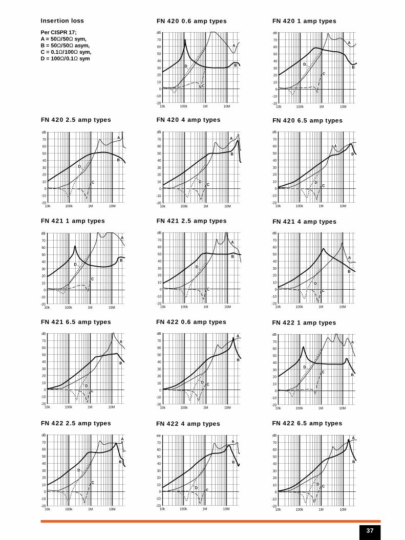
FN 420 0.6 amp types
FN 420 4 amp types
FN 420 1 amp types
FN 420 2.5 amp types
10k 100k 1M 10M-20
-10
0
10
20
30
40
50
60
70
dB
BD
A
C
10k 100k 1M 10M-20
-10
0
10
20
30
40
50
60
70
dB
BD
A
C
10k 100k 1M 10M-20
-10
0
10
20
30
40
50
60
70
dB
B
D
A
C
FN 420 6.5 amp types
FN 421 1 amp types
10k 100k 1M 10M-20
-10
0
10
20
30
40
50
60
70
dB
B
D
A
C
10k 100k 1M 10M-20
-10
0
10
20
30
40
50
60
70
dB
BD
A
C
10k 100k 1M 10M-20
-10
0
10
20
30
40
50
60
70
dB
B
D
A
C
FN 421 2.5 amp types FN 421 4 amp types
FN 421 6.5 amp types
10k 100k 1M 10M-20
-10
0
10
20
30
40
50
60
70
dB
B
D
A
C
10k 100k 1M 10M-20
-10
0
10
20
30
40
50
60
70
dB
B
D
A
C
10k 100k 1M 10M-20
-10
0
10
20
30
40
50
60
70
dB
B
D
A
C
FN 422 0.6 amp types FN 422 1 amp types
FN 422 2.5 amp types
10k 100k 1M 10M-20
-10
0
10
20
30
40
50
60
70
dB
B
D
A
C
10k 100k 1M 10M-20
-10
0
10
20
30
40
50
60
70
dB
B
D
A
C
10k 100k 1M 10M-20
-10
0
10
20
30
40
50
60
70
dB
B
D
A
C
FN 422 4 amp types FN 422 6.5 amp types
10k 100k 1M 10M-20
-10
0
10
20
30
40
50
60
70
dB
B
D
A
C
10k 100k 1M 10M-20
-10
0
10
20
30
40
50
60
70
dB
B
D
A
C
Insertion loss
Per CISPR 17; A = 50Ω/50Ω sym, B = 50Ω/50Ω asym, C = 0.1Ω/100Ω sym, D = 100Ω/0.1Ω sym
37
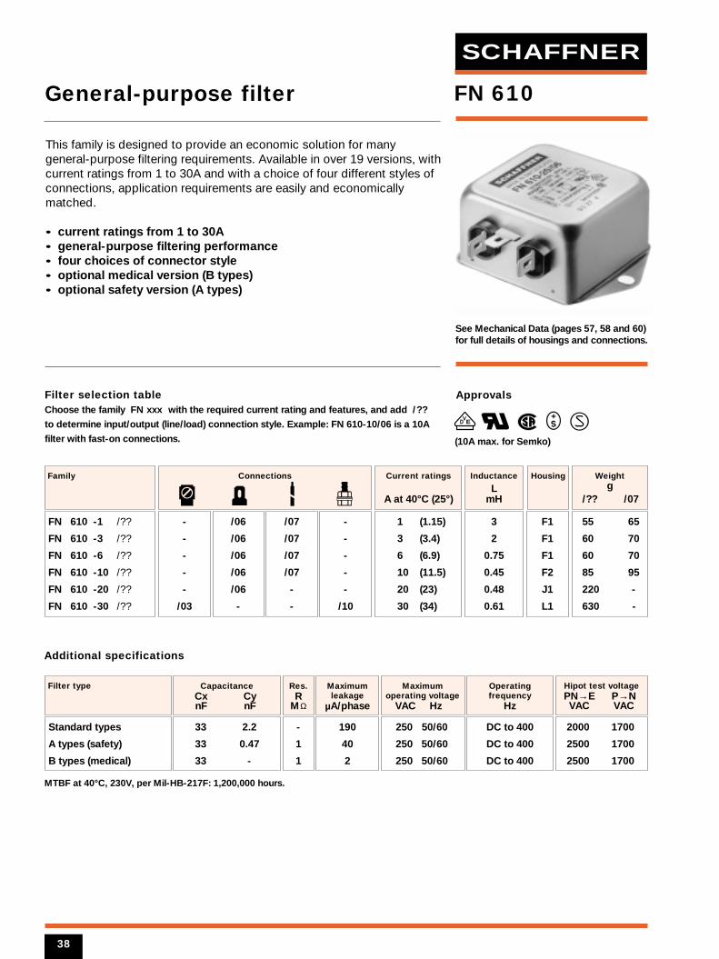
Filter selection tableChoose the family FN xxx with the required current rating and features, and add /??
to determine input/output (line/load) connection style. Example: FN 610-10/06 is a 10A
filter with fast-on connections.
See Mechanical Data (pages 57, 58 and 60)for full details of housings and connections.
1 (1.15)
3 (3.4)
6 (6.9)
10 (11.5)
20 (23)
30 (34)
Current ratings
A at 40°C (25°)
FN 610 -1 /??
FN 610 -3 /??
FN 610 -6 /??
FN 610 -10 /??
FN 610 -20 /??
FN 610 -30 /??
Family
-
-
-
-
-
/03
/06
/06
/06
/06
/06
-
/07
/07
/07
/07
-
-
-
-
-
-
-
/10
Connections
F1
F1
F1
F2
J1
L1
Housing
3
2
0.75
0.45
0.48
0.61
Inductance
LmH
33 2.2
33 0.47
33 -
CapacitanceCx Cy nF nF
2000 1700
2500 1700
2500 1700
Filter type
-
1
1
Res.R
MΩ
190
40
2
Maximumleakage
µA/phase
250 50/60
250 50/60
250 50/60
Maximumoperating voltage
VAC Hz
Hipot test voltagePN→E P→N VAC VAC
Operatingfrequency
Hz
DC to 400
DC to 400
DC to 400
MTBF at 40°C, 230V, per Mil-HB-217F: 1,200,000 hours.
Additional specifications
Approvals
VED
FN 610
55 65
60 70
60 70
85 95
220 -
630 -
Weightg
/?? /07
This family is designed to provide an economic solution for manygeneral-purpose filtering requirements. Available in over 19 versions, withcurrent ratings from 1 to 30A and with a choice of four different styles ofconnections, application requirements are easily and economicallymatched.
• current ratings from 1 to 30A• general-purpose filtering performance• four choices of connector style• optional medical version (B types)• optional safety version (A types)
General-purpose filter
Standard types
A types (safety)
B types (medical)
(10A max. for Semko)
38
SCHAFFNER
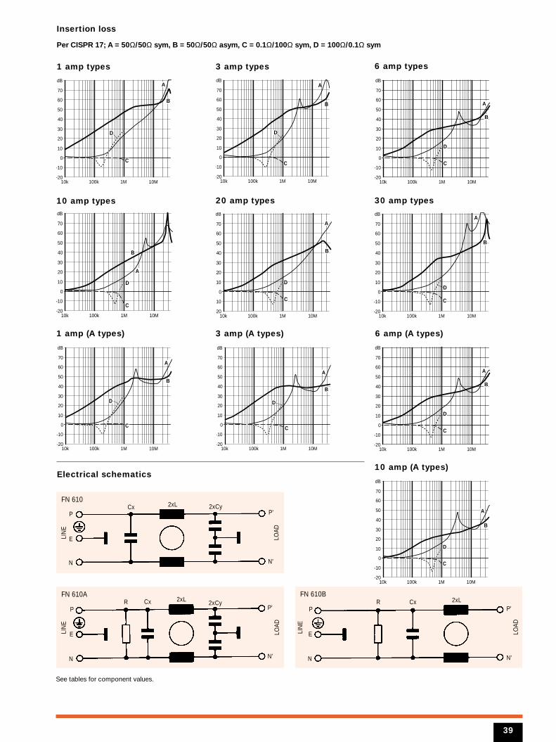
Insertion loss
Per CISPR 17; A = 50Ω/50Ω sym, B = 50Ω/50Ω asym, C = 0.1Ω/100Ω sym, D = 100Ω/0.1Ω sym
1 amp types
10 amp types
3 amp types 6 amp types
Electrical schematics
10k 100k 1M 10M-20
-10
0
10
20
30
40
50
60
70
dB
B
D
A
C
A
B
10k 100k 1M 10M-20
-10
0
10
20
30
40
50
60
70
dB
D
C
10k 100k 1M 10M-20
-10
0
10
20
30
40
50
60
70
dB
B
A
C
D
20 amp types 30 amp types
10k 100k 1M 10M-20
-10
0
10
20
30
40
50
60
70
dB
B
A
C
D
10k 100k 1M 10M-20
-10
0
10
20
30
40
50
60
70
dB
B
A
C
D
10k 100k 1M 10M-20
-10
0
10
20
30
40
50
60
70
dB
B
A
C
D
1 amp (A types) 3 amp (A types)
10 amp (A types)
10k 100k 1M 10M-20
-10
0
10
20
30
40
50
60
70
dB
B
A
C
D
6 amp (A types)
10k 100k 1M 10M-20
-10
0
10
20
30
40
50
60
70
dB
B
A
C
D
10k 100k 1M 10M-20
-10
0
10
20
30
40
50
60
70
dB
B
A
C
D
10k 100k 1M 10M-20
-10
0
10
20
30
40
50
60
70
dB
B
A
C
D
N
2xLCxFN 610
LIN
E
LOAD
2xCy
E
P
N'
P'
N
2xLCxRFN 610A
LIN
E
LOAD
2xCy
E
P
N'
P'
N
2xLCxRFN 610B
LIN
E
LOAD
E
P
N'
P'
See tables for component values.
39
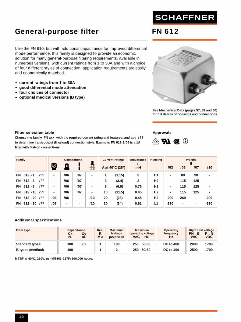
Filter selection tableChoose the family FN xxx with the required current rating and features, and add /??
to determine input/output (line/load) connection style. Example: FN 612-1/06 is a 1A
filter with fast-on connections.
See Mechanical Data (pages 57, 58 and 60)for full details of housings and connections.
1 (1.15)
3 (3.4)
6 (6.9)
10 (11.5)
20 (23)
30 (34)
Current ratings
A at 40°C (25°)
FN 612 -1 /??
FN 612 -3 /??
FN 612 -6 /??
FN 612 -10 /??
FN 612 -20 /??
FN 612 -30 /??
Family
-
-
-
-
/03
/03
/06
/06
/06
/06
/06
-
/07
/07
/07
/07
-
-
-
-
-
-
/10
/10
Connections
H1
H2
H2
H2
H2
L1
Housing
3
2
0.75
0.45
0.48
0.61
Inductance
LmH
100 2.2
100 -
CapacitanceCx Cy nF nF
2000 1700
2500 1700
Filter type
1
1
Res.R
MΩ
190
2
Maximumleakage
µA/phase
250 50/60
250 50/60
Maximumoperating voltage
VAC Hz
Hipot test voltagePN→E P→N VAC VDC
Operatingfrequency
Hz
DC to 400
DC to 400
MTBF at 40°C, 230V, per Mil-HB-217F: 800,000 hours.
Additional specifications
Approvals
VED
FN 612
- 80 90 -
- 115 125 -
- 115 125 -
- 115 125 -
290 260 - 290
630 - - 630
Weightg
/03 /06 /07 /10
Like the FN 610, but with additional capacitance for improved differentialmode performance, this family is designed to provide an economicsolution for many general-purpose filtering requirements. Available innumerous versions, with current ratings from 1 to 30A and with a choiceof four different styles of connection, application requirements are easilyand economically matched.
• current ratings from 1 to 30A• good differential mode attenuation• four choices of connector• optional medical versions (B type)
General-purpose filter
Standard types
B types (medical)
40
SCHAFFNER
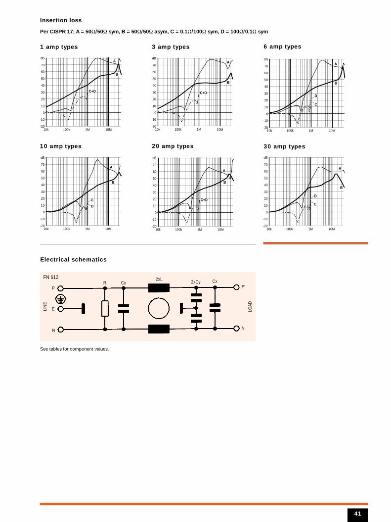
Insertion loss
Per CISPR 17; A = 50Ω/50Ω sym, B = 50Ω/50Ω asym, C = 0.1Ω/100Ω sym, D = 100Ω/0.1Ω sym
1 amp types
10 amp types
3 amp types 6 amp types
Electrical schematics
10k 100k 1M 10M-20
-10
0
10
20
30
40
50
60
70
dB
B
A
C+D
10k 100k 1M 10M-20
-10
0
10
20
30
40
50
60
70
dB
B
A
C+D
10k 100k 1M 10M-20
-10
0
10
20
30
40
50
60
70
dB
B
A
D
C
20 amp types 30 amp types
10k 100k 1M 10M-20
-10
0
10
20
30
40
50
60
70
dB
B
A
C+D
10k 100k 1M 10M-20
-10
0
10
20
30
40
50
60
70
dB
B
A
D
C
10k 100k 1M 10M-20
-10
0
10
20
30
40
50
60
70
dB
B
A
D
C
N
2xLCx CxR
FN 612
LIN
E
LOAD
2xCy
E
P
N'
P'
See tables for component values.
41
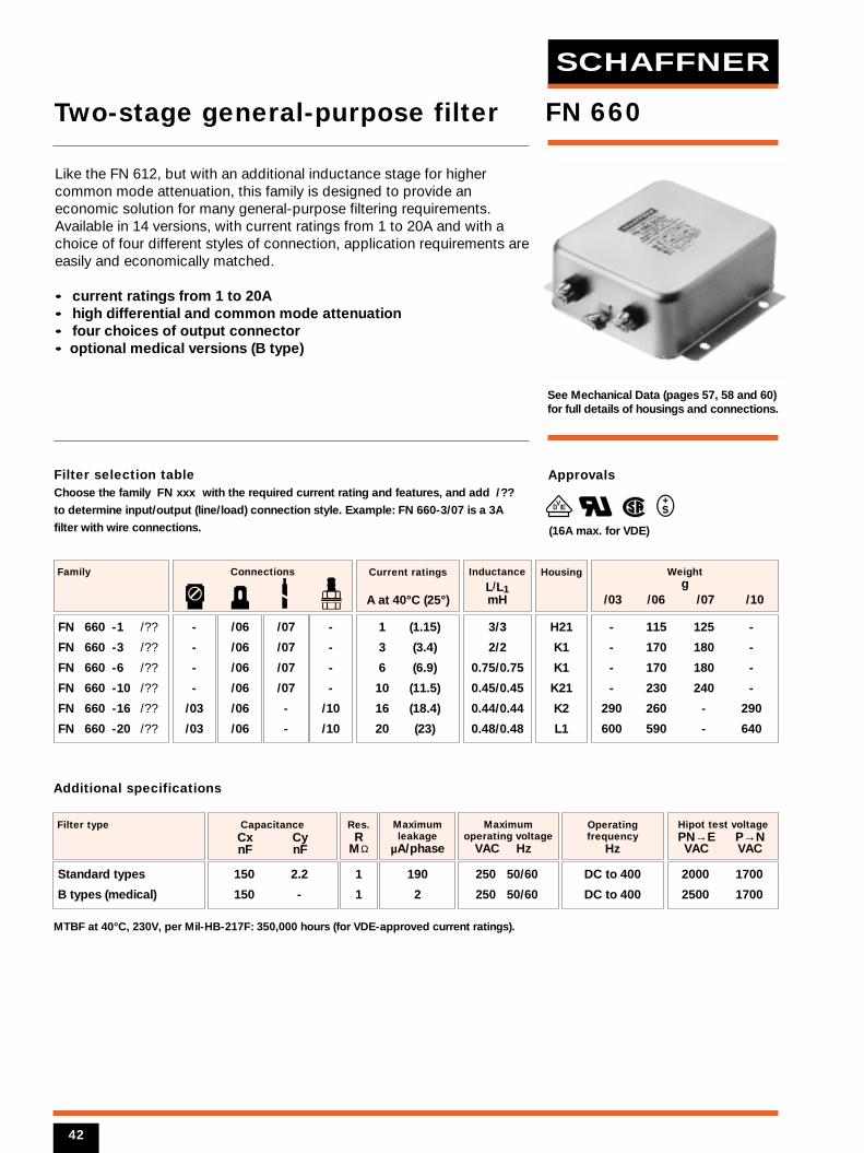
Filter selection tableChoose the family FN xxx with the required current rating and features, and add /??
to determine input/output (line/load) connection style. Example: FN 660-3/07 is a 3A
filter with wire connections.
See Mechanical Data (pages 57, 58 and 60)for full details of housings and connections.
1 (1.15)
3 (3.4)
6 (6.9)
10 (11.5)
16 (18.4)
20 (23)
Current ratings
A at 40°C (25°)
FN 660 -1 /??
FN 660 -3 /??
FN 660 -6 /??
FN 660 -10 /??
FN 660 -16 /??
FN 660 -20 /??
Family
-
-
-
-
/03
/03
/06
/06
/06
/06
/06
/06
/07
/07
/07
/07
-
-
-
-
-
-
/10
/10
Connections
H21
K1
K1
K21
K2
L1
Housing
3/3
2/2
0.75/0.75
0.45/0.45
0.44/0.44
0.48/0.48
Inductance
L/L1mH
150 2.2
150 -
CapacitanceCx Cy nF nF
2000 1700
2500 1700
Filter type
1
1
Res.R
MΩ
190
2
Maximumleakage
µA/phase
250 50/60
250 50/60
Maximumoperating voltage
VAC Hz
Hipot test voltagePN→E P→N VAC VAC
Operatingfrequency
Hz
DC to 400
DC to 400
MTBF at 40°C, 230V, per Mil-HB-217F: 350,000 hours (for VDE-approved current ratings).
Additional specifications
Approvals
VED
FN 660
- 115 125 -
- 170 180 -
- 170 180 -
- 230 240 -
290 260 - 290
600 590 - 640
Weightg
/03 /06 /07 /10
Like the FN 612, but with an additional inductance stage for highercommon mode attenuation, this family is designed to provide aneconomic solution for many general-purpose filtering requirements.Available in 14 versions, with current ratings from 1 to 20A and with achoice of four different styles of connection, application requirements areeasily and economically matched.
• current ratings from 1 to 20A• high differential and common mode attenuation• four choices of output connector• optional medical versions (B type)
Two-stage general-purpose filter
Standard types
B types (medical)
(16A max. for VDE)
42
SCHAFFNER
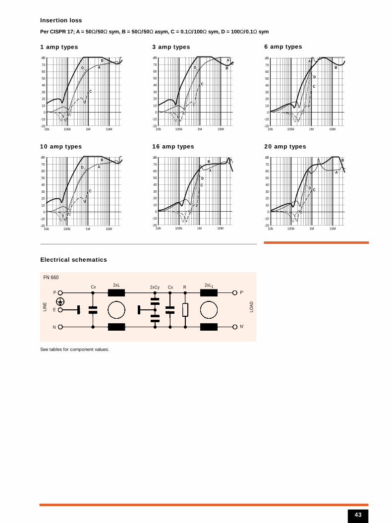
Insertion loss
Per CISPR 17; A = 50Ω/50Ω sym, B = 50Ω/50Ω asym, C = 0.1Ω/100Ω sym, D = 100Ω/0.1Ω sym
1 amp types
10 amp types
3 amp types 6 amp types
Electrical schematics
10k 100k 1M 10M-20
-10
0
10
20
30
40
50
60
70
dBB
AD
C
10k 100k 1M 10M-20
-10
0
10
20
30
40
50
60
70
dB
B
A
D
C
10k 100k 1M 10M-20
-10
0
10
20
30
40
50
60
70
dB
B
A
D
C
16 amp types 20 amp types
10k 100k 1M 10M-20
-10
0
10
20
30
40
50
60
70
dBB
A
D
C
10k 100k 1M 10M-20
-10
0
10
20
30
40
50
60
70
dBB
A
D C
10k 100k 1M 10M-20
-10
0
10
20
30
40
50
60
70
dBB
AD
C
N
2xL 2xL1Cx
FN 660
LIN
E
LOAD
2xCy Cx R
E
P
N'
P'
See tables for component values.
43
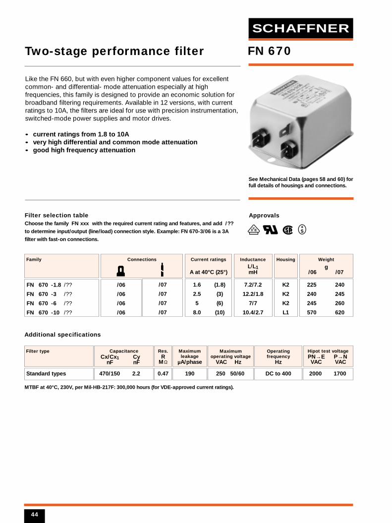
Filter selection tableChoose the family FN xxx with the required current rating and features, and add /??
to determine input/output (line/load) connection style. Example: FN 670-3/06 is a 3A
filter with fast-on connections.
See Mechanical Data (pages 58 and 60) forfull details of housings and connections.
1.6 (1.8)
2.5 (3)
5 (6)
8.0 (10)
Current ratings
A at 40°C (25°)
FN 670 -1.8 /??
FN 670 -3 /??
FN 670 -6 /??
FN 670 -10 /??
Family
/06
/06
/06
/06
/07
/07
/07
/07
Connections
K2
K2
K2
L1
Housing
7.2/7.2
12.2/1.8
7/7
10.4/2.7
Inductance
L/L1mH
470/150 2.2
CapacitanceCx/Cx1 Cy
nF nF
2000 1700
Filter type
0.47
Res.R
MΩ
190
Maximumleakage
µA/phase
250 50/60
Maximumoperating voltage
VAC Hz
Hipot test voltagePN→E P→N VAC VAC
Operatingfrequency
Hz
DC to 400
MTBF at 40°C, 230V, per Mil-HB-217F: 300,000 hours (for VDE-approved current ratings).
Additional specifications
Approvals
VED
FN 670
225 240
240 245
245 260
570 620
Weight
g/06 /07
Like the FN 660, but with even higher component values for excellentcommon- and differential- mode attenuation especially at highfrequencies, this family is designed to provide an economic solution forbroadband filtering requirements. Available in 12 versions, with currentratings to 10A, the filters are ideal for use with precision instrumentation,switched-mode power supplies and motor drives.
• current ratings from 1.8 to 10A• very high differential and common mode attenuation• good high frequency attenuation
Two-stage performance filter
Standard types
44
SCHAFFNER
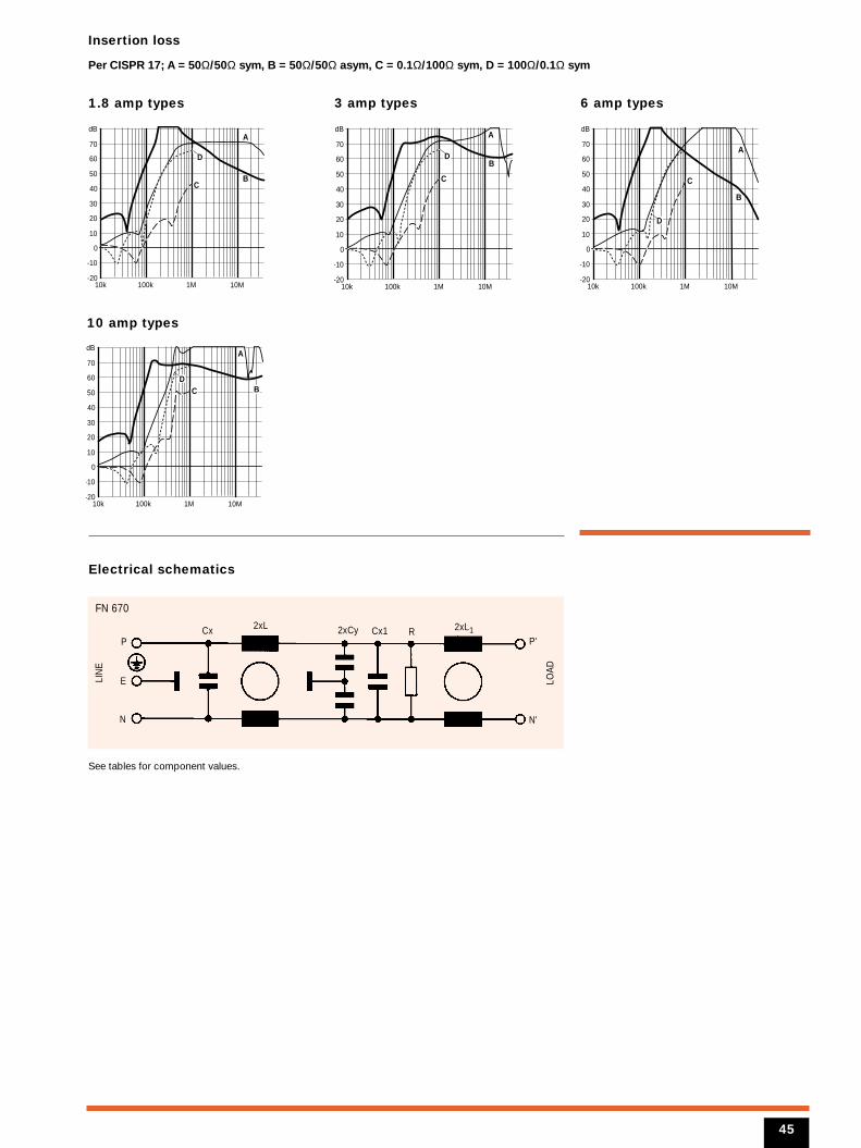
Insertion loss
Per CISPR 17; A = 50Ω/50Ω sym, B = 50Ω/50Ω asym, C = 0.1Ω/100Ω sym, D = 100Ω/0.1Ω sym
1.8 amp types 3 amp types
10 amp types
Electrical schematics
10k 100k 1M 10M-20
-10
0
10
20
30
40
50
60
70
dB
B
A
D
C
10k 100k 1M 10M-20
-10
0
10
20
30
40
50
60
70
dB
B
A
D
C
6 amp types
10k 100k 1M 10M-20
-10
0
10
20
30
40
50
60
70
dB
B
A
D
C
A
10k 100k 1M 10M-20
-10
0
10
20
30
40
50
60
70
dB
BD
C
N
2xL 2xL1Cx Cx1 R
FN 670
LIN
E
LOAD
2xCy
E
P
N'
P'
See tables for component values.
45
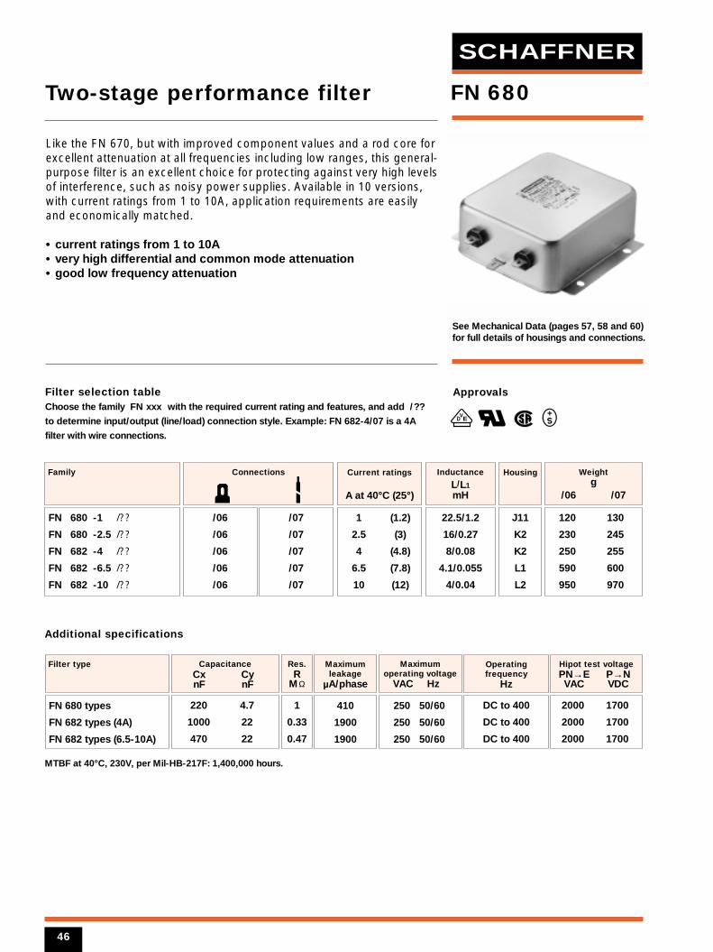
Filter selection tableChoose the family FN xxx with the required current rating and features, and add /??
to determine input/output (line/load) connection style. Example: FN 682-4/07 is a 4A
filter with wire connections.
See Mechanical Data (pages 57, 58 and 60)for full details of housings and connections.
1 (1.2)
2.5 (3)
4 (4.8)
6.5 (7.8)
10 (12)
Current ratings
A at 40°C (25°)
FN 680 -1 /??
FN 680 -2.5 /??
FN 682 -4 /??
FN 682 -6.5 /??
FN 682 -10 /??
Family
/06
/06
/06
/06
/06
/07
/07
/07
/07
/07
Connections
J11
K2
K2
L1
L2
Housing
22.5/1.2
16/0.27
8/0.08
4.1/0.055
4/0.04
Inductance
L/L1
mH
220 4.7
1000 22
470 22
CapacitanceCx Cy nF nF
2000 1700
2000 1700
2000 1700
Filter type
1
0.33
0.47
Res.R
MΩ
410
1900
1900
Maximumleakage
µA/phase
250 50/60
250 50/60
250 50/60
Maximumoperating voltage
VAC Hz
Hipot test voltagePN→E P→N VAC VDC
Operatingfrequency
Hz
DC to 400
DC to 400
DC to 400
MTBF at 40°C, 230V, per Mil-HB-217F: 1,400,000 hours.
Additional specifications
Approvals
VED
FN 680
120 130
230 245
250 255
590 600
950 970
Weight g
/06 /07
Like the FN 670, but with improved component values and a rod core forexcellent attenuation at all frequencies including low ranges, this general-purpose filter is an excellent choice for protecting against very high levelsof interference, such as noisy power supplies. Available in 10 versions,with current ratings from 1 to 10A, application requirements are easilyand economically matched.
• current ratings from 1 to 10A• very high differential and common mode attenuation• good low frequency attenuation
Two-stage performance filter
FN 680 types
FN 682 types (4A)
FN 682 types (6.5-10A)
46
SCHAFFNER
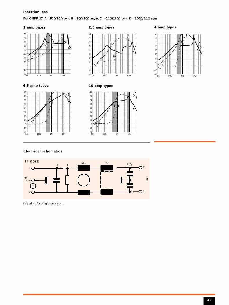
Insertion loss
Per CISPR 17; A = 50Ω/50Ω sym, B = 50Ω/50Ω asym, C = 0.1Ω/100Ω sym, D = 100Ω/0.1Ω sym
1 amp types
6.5 amp types
2.5 amp types 4 amp types
Electrical schematics
10k 100k 1M 10M-20
-10
0
10
20
30
40
50
60
70
dB
BD
C
A
10k 100k 1M 10M-20
-10
0
10
20
30
40
50
60
70
dB
B
D
C
A
10 amp types
10k 100k 1M 10M-20
-10
0
10
20
30
40
50
60
70
dB
BD C
A
10k 100k 1M 10M-20
-10
0
10
20
30
40
50
60
70
dB
B
DC A
10k 100k 1M 10M-20
-10
0
10
20
30
40
50
60
70
dB
B
D
C
A
N
2xL 2xL1Cx R
FN 680/682
LIN
E
LOAD
2xCy
E
P
N'
P'
See tables for component values.
47
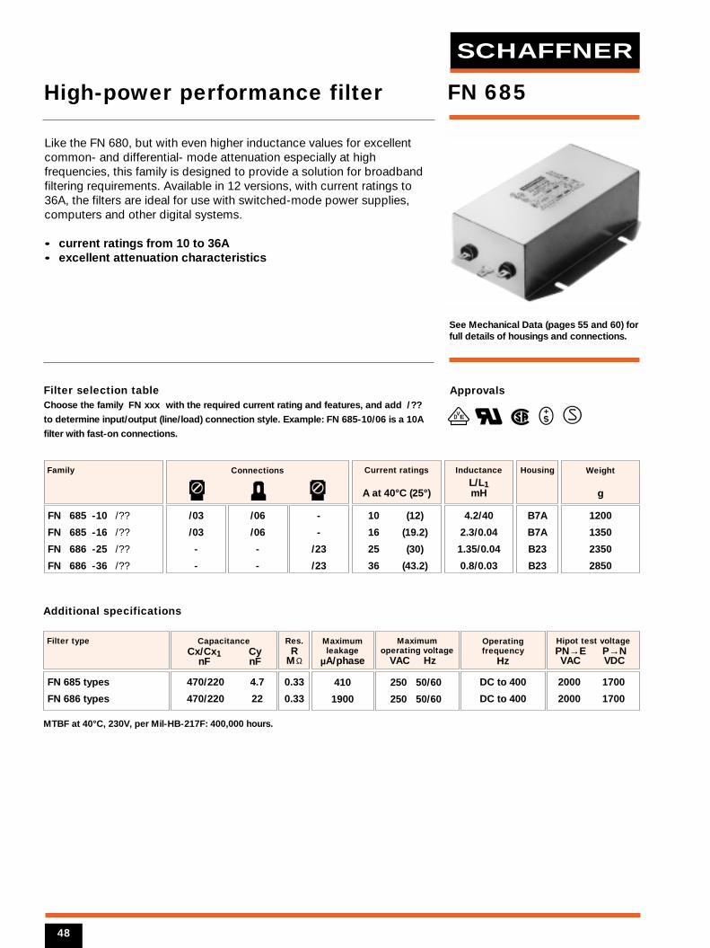
Filter selection tableChoose the family FN xxx with the required current rating and features, and add /??
to determine input/output (line/load) connection style. Example: FN 685-10/06 is a 10A
filter with fast-on connections.
See Mechanical Data (pages 55 and 60) forfull details of housings and connections.
10 (12)
16 (19.2)
25 (30)
36 (43.2)
Current ratings
A at 40°C (25°)
FN 685 -10 /??
FN 685 -16 /??
FN 686 -25 /??
FN 686 -36 /??
Family
/03
/03
-
-
/06
/06
-
-
-
-
/23
/23
Connections
B7A
B7A
B23
B23
Housing
4.2/40
2.3/0.04
1.35/0.04
0.8/0.03
Inductance
L/L1mH
470/220 4.7
470/220 22
CapacitanceCx/Cx1 Cy
nF nF
2000 1700
2000 1700
Filter type
0.33
0.33
Res.R
MΩ
410
1900
Maximumleakage
µA/phase
250 50/60
250 50/60
Maximumoperating voltage
VAC Hz
Hipot test voltagePN→E P→N VAC VDC
Operatingfrequency
Hz
DC to 400
DC to 400
MTBF at 40°C, 230V, per Mil-HB-217F: 400,000 hours.
Additional specifications
Approvals
VED
FN 685
1200
1350
2350
2850
Weight
g
Like the FN 680, but with even higher inductance values for excellentcommon- and differential- mode attenuation especially at highfrequencies, this family is designed to provide a solution for broadbandfiltering requirements. Available in 12 versions, with current ratings to36A, the filters are ideal for use with switched-mode power supplies,computers and other digital systems.
• current ratings from 10 to 36A• excellent attenuation characteristics
High-power performance filter
FN 685 types
FN 686 types
48
SCHAFFNER
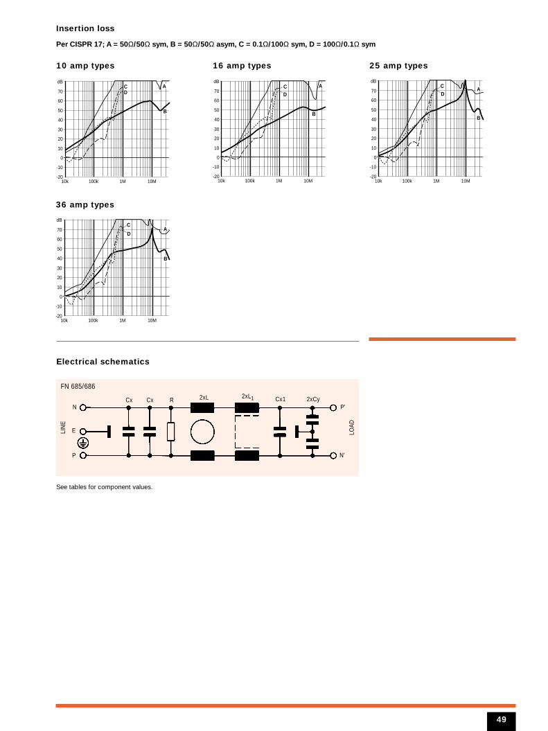
Insertion loss
Per CISPR 17; A = 50Ω/50Ω sym, B = 50Ω/50Ω asym, C = 0.1Ω/100Ω sym, D = 100Ω/0.1Ω sym
10 amp types
36 amp types
16 amp types
Electrical schematics
10k 100k 1M 10M-20
-10
0
10
20
30
40
50
60
70
dB
B
DC A
10k 100k 1M 10M-20
-10
0
10
20
30
40
50
60
70
dB
B
DC A
25 amp types
10k 100k 1M 10M-20
-10
0
10
20
30
40
50
60
70
dB
B
DC
A
10k 100k 1M 10M-20
-10
0
10
20
30
40
50
60
70
dB
B
D
CA
N
2xLCx Cx R
FN 685/686
LIN
E
LOAD
2xL1 2xCyCx1
E
P N'
P'
See tables for component values.
49
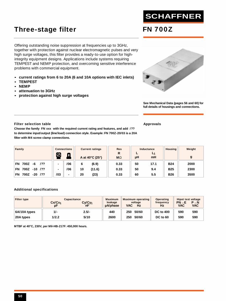
Filter selection tableChoose the family FN xxx with the required current rating and features, and add /??
to determine input/output (line/load) connection style. Example: FN 700Z-20/03 is a 20A
filter with M4 screw clamp connections.
See Mechanical Data (pages 56 and 60) forfull details of housings and connections.
6 (6.9)
10 (11.6)
20 (23)
Current ratings
A at 40°C (25°)
FN 700Z -6 /??
FN 700Z -10 /??
FN 700Z -20 /??
Family
-
-
/03
/06
/06
-
Connections
B24
B25
B26
Housing
50 17.1
50 9.4
60 5.5
Inductance
L L1µH mH
0.33
0.33
0.33
Res
RMΩ
1/- 2.5/-
1/2.2 5/10
CapacitanceCx/Cx1 Cy/Cy1
µF nF
590 590
590 590
Filter type
440
2600
Maximumleakage
µA/phase
250 50/60
250 50/60
Maximum operatingvoltage
VAC Hz
Hipot test voltagePN→E P→N VAC VAC
Operatingfrequency
Hz
DC to 400
DC to 60
MTBF at 40°C, 230V, per Mil-HB-217F: 450,000 hours.
Additional specifications
Approvals
FN 700Z
2000
2300
3500
Weight
g
Offering outstanding noise suppression at frequencies up to 3GHz,together with protection against nuclear electromagnetic pulses and veryhigh surge voltages, this filter provides a ready-to-use option for high-integrity equipment designs. Applications include systems requiringTEMPEST and NEMP protection, and overcoming sensitive interferenceproblems with commercial equipment.
• current ratings from 6 to 20A (6 and 10A options with IEC inlets)• TEMPEST• NEMP• attenuation to 3GHz• protection against high surge voltages
Three-stage filter
6A/10A types
20A types
50
SCHAFFNER
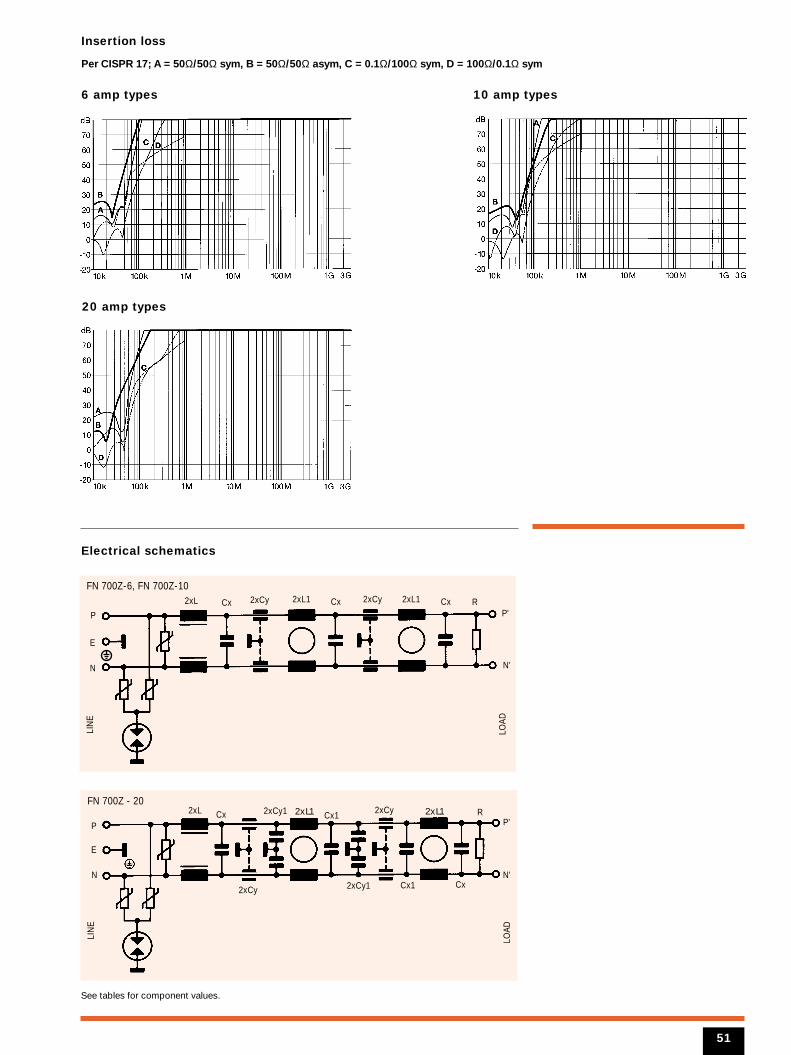
Insertion loss
Per CISPR 17; A = 50Ω/50Ω sym, B = 50Ω/50Ω asym, C = 0.1Ω/100Ω sym, D = 100Ω/0.1Ω sym
6 amp types
Electrical schematics
10 amp types
20 amp types
N
RCx Cx1
CxCx1
2xCy1 2xCy
2xCy1
2xLFN 700Z - 20
LIN
E
LOAD
2xCy
E
P
N'
P'
See tables for component values.
51
N
2xL Cx Cx Cx
FN 700Z-6, FN 700Z-10
LIN
E
LOAD
2xCy 2xCy2xL1 2xL1
E
P
N'
RP'
2xL1 2xL1
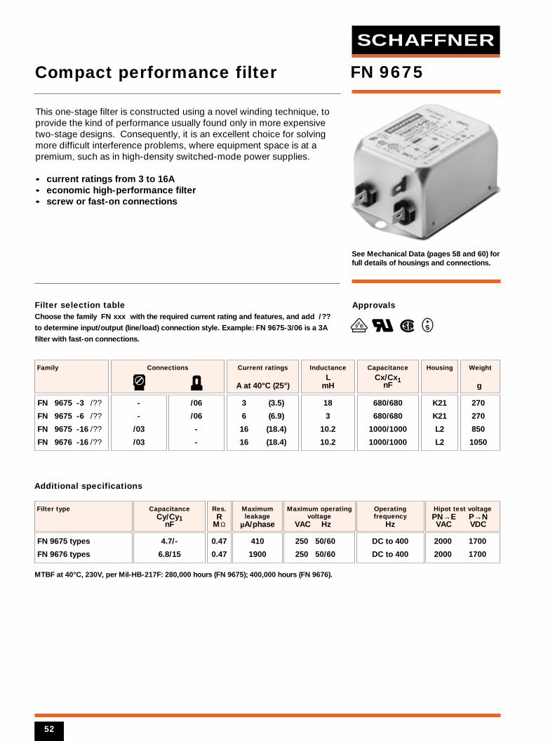
Filter selection tableChoose the family FN xxx with the required current rating and features, and add /??
to determine input/output (line/load) connection style. Example: FN 9675-3/06 is a 3A
filter with fast-on connections.
See Mechanical Data (pages 58 and 60) forfull details of housings and connections.
3 (3.5)
6 (6.9)
16 (18.4)
16 (18.4)
Current ratings
A at 40°C (25°)
FN 9675 -3 /??
FN 9675 -6 /??
FN 9675 -16 /??
FN 9676 -16 /??
Family
-
-
/03
/03
/06
/06
-
-
Connections
K21
K21
L2
L2
Housing
18
3
10.2
10.2
Inductance
LmH
680/680
680/680
1000/1000
1000/1000
Capacitance
Cx/Cx1nF
4.7/-
6.8/15
CapacitanceCy/Cy1
nF
2000 1700
2000 1700
Filter type
0.47
0.47
Res.R
MΩ
410
1900
Maximumleakage
µA/phase
250 50/60
250 50/60
Maximum operatingvoltage
VAC Hz
Hipot test voltagePN→E P→N VAC VDC
Operatingfrequency
Hz
DC to 400
DC to 400
MTBF at 40°C, 230V, per Mil-HB-217F: 280,000 hours (FN 9675); 400,000 hours (FN 9676).
Additional specifications
Approvals
VED
FN 9675
270
270
850
1050
Weight
g
This one-stage filter is constructed using a novel winding technique, toprovide the kind of performance usually found only in more expensivetwo-stage designs. Consequently, it is an excellent choice for solvingmore difficult interference problems, where equipment space is at apremium, such as in high-density switched-mode power supplies.
• current ratings from 3 to 16A• economic high-performance filter• screw or fast-on connections
Compact performance filter
FN 9675 types
FN 9676 types
52
SCHAFFNER
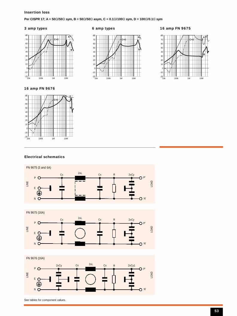
Insertion loss
Per CISPR 17; A = 50Ω/50Ω sym, B = 50Ω/50Ω asym, C = 0.1Ω/100Ω sym, D = 100Ω/0.1Ω sym
3 amp types
16 amp FN 9676
6 amp types
Electrical schematics
10k 100k 1M 10M-20
-10
0
10
20
30
40
50
60
70
dB
B
AC+D
10k 100k 1M 10M-20
-10
0
10
20
30
40
50
60
70
dB
B
AC+D
16 amp FN 9675
10k 100k 1M 10M-20
-10
0
10
20
30
40
50
60
70
dB
B
AC+D
10k 100k 1M 10M-20
-10
0
10
20
30
40
50
60
70
dB
B
A
C+D
N
2xL 2xCyCx
FN 9675 (3 and 6A)
LIN
E
LOAD
Cx R
E
P
N'
P'
N
2xL 2xCyCx
FN 9675 (16A)
LIN
E
LOAD
Cx R
E
P
N'
P'
N
2xL2xCy 2xCy1Cx
FN 9676 (16A)
LIN
E
LOAD
Cx R
E
P
N'
P'
53
See tables for component values.
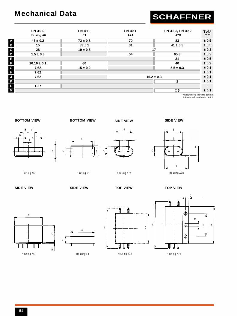
Mechanical Data
ABCDEFGHJKLM
45 ± 0.2 70 8372 ± 0.815 31 41 ± 0.333 ± 128 1719 ± 0.5
1.5 ± 0.3 54 65.831
10.16 ± 0.1 40607.62 5.5 ± 0.315 ± 0.27.627.62 15.2 ± 0.3
11.27
∅ 5
FN 406 FN 410 FN 421 FN 420, FN 422Housing A6 E1 A7A A7B
BOTTOM VIEW BOTTOM VIEW SIDE VIEW SIDE VIEW
SIDE VIEW TOP VIEWSIDE VIEW TOP VIEW
± 0.5± 0.5± 0.3± 0.2± 0.5± 0.2± 0.1± 0.1± 0.1± 0.1
-± 0.1
Tol.*mm
FH
L
B
J
C
E
J
C
B
K
G J
B
Housing A6
Housing A6 Housing A7A
Housing A7BHousing E1 Housing A7A
Housing A7BHousing E1
A
DDF
M
G
C
A
G
F
B
AA
C
D
* Measurements share this commontolerance unless otherwise stated.
54
SCHAFFNER
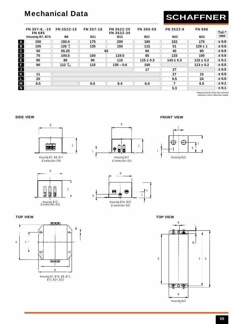
55
Mechanical Data
ABCDEFJKLMN
150 150.5 175 200 180 152 170105 126 +0
-1 130
100
150 115 51 129 ± 150 55.25 65 60 45 6075 100.5 119.5 85
6.4
133 10085 85 90 115 115 ± 0.3 143 ± 0.3 115 ± 0.290 112 +0
-0.4 115
6.5
135 – 0.6
6.4
10017
113 ± 0.227
11 27 1520 9.5 246.5 7 6.5
5.3
FN 357-6, -10 FN 352Z-10 FN 357-16 FN 352Z-20 FN 350-55 FN 352Z-6 FN 686FN 685 FN 353Z-30
Housing B7, B7A B8 B11 B13 B21 B22 B23
± 0.5± 0.5± 0.5± 0.5± 0.1± 0.5± 0.5± 0.5± 0.5± 0.1± 0.1
Tol.*mm
SIDE VIEW
TOP VIEW
FRONT VIEW
TOP VIEW
D
Housing B7, B8, B11(Connection /29)
Housing B7, B7A, B8, B11,B13, B21, B23
Housing B21(Connection /33)
Housing B13(Connection /33)
Housing B22
Housing B7A, B23(Connection /03)
D
J
C
DD
CLK
J
LK
CC
A E
F
B
M
N
M
E A
B
D
* Measurements share this commontolerance unless otherwise stated.
C
Housing B22
SCHAFFNER
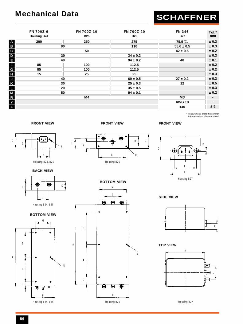
Mechanical Data
ABCDEFGHJKLMRYZ
200 250 27580 110
503040 94 ± 0.2
85 100 112.585 100 112.515 25 25
40 60 ± 0.530 25 ± 0.320 35 ± 0.550 94 ± 0.1
M4 M3
75.9 +0-0.3
55.6 ± 0.5
34 ± 0.242 ± 0.5
40
AWG 18140
27 ± 0.212
FN 700Z-6 FN 700Z-10 FN 700Z-20 FN 346Housing B24 B25 B26 B27
± 0.3± 0.3± 0.2± 0.3± 0.1± 0.2± 0.2± 0.3± 0.3± 0.5± 0.3± 0.2
--
± 5
Tol.*mm
BACK VIEW
FRONT VIEW FRONT VIEW
BOTTOM VIEW
BOTTOM VIEW
A
M
H
G
FR
J
Housing B24, B25
Housing B24, B25 Housing B26
Housing B26Housing B24, B25
KL
B
D
E
R
E
KL
CD
R
C
J
M
A
G
FF
H
B
R
* Measurements share this commontolerance unless otherwise stated.
FRONT VIEW
SIDE VIEW
TOP VIEW
R
E
B
A
K
C
Housing B27
J
Housing B27
56
SCHAFFNER

57
Mechanical Data
ABCDFJKLMNYZ
64 45 71 8533 41 46.6 ± 1 54 ± 1
19 29 24.8 22 ± 1 29 ± 1 40 ± 144 29 ± 0.5 50.5 ± 1 65 ± 154 37 ± 0.4 61 7521 12.5 ± 0.2 21 279 9.6 ± 0.2 10.5 1215 18.7 16.5 24.5 29.5
7146.6 ± 1 52.629 ± 1 29
50.5 ± 1 50.5 ± 161
21(J1) 8.5(J2)
10.5 ± 0.319
5.3 3.5 5.3
211420
7069
30 ± 149.8 ± 160 ± 0.2
2712
6.3 3.9 6.36 6
140 140
FN 610 FN 610-10 FN 332 FN 612-1 FN 612 FN 612 FN 660-1 FN 610 FN 680-1 FN 343-1-3-6 -3-6-10 -20 -20
Housing F1 F2 G1 H1 H2 H2 H21 J1 J11 J2
FRONT VIEW
TOP VIEW
± 0.5± 0.5± 0.5± 0.3± 0.2± 0.5± 0.5± 0.5± 0.1± 0.1± 1+ 5
Tol.*mm
L
J
KC
M
N
B
K
J
C
J
LK
C
N N
B
K
C
J
J1
J2
M
B
Housing F1, F2, G1H1, H2, J1, K2
Housing H1, H2, J1, J11, J2Housing F1, F2, G1
Housing K2
Housing H21, K1
Housing H21, K1, K2, K21
Housing J2
Housing J11
D FA
L
LC
K
M
A
F
D
A
F
D
* Measurements share this commontolerance unless otherwise stated.
SCHAFFNER
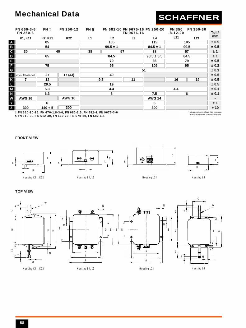
Mechanical Data
ABCDEFGJKLMNWYZ
85 105 11954 99.5 ± 1 84.5 ± 1
30 40 38 57 3865 84.5 98.5 ± 0.5
79 6675 95 109
5127(J1) 8.5(J2)17(J3) 27
1217 (J3) 40
7 119.529.5 195.3 4.4 4.46.3 6 7.5
AWG 16 AWG 16 AWG 146 6
300 300 300140 + 5
10599.557
84.57995
16 19
6
FN 660-3-6FN 250-6
K1, K11
FN ‡
K2, K21
FN 250-12
K22
FN §
L1
FN 682-10
L2
FN 9675-16FN 9676-16
L2
FN 250-20
L4
FN 350-8-12-20
L21
FN 350-30
L21
K
BJ3
C
FRONT VIEW
TOP VIEW
K LC
J
± 0.5± 0.5± 1± 1
± 0.5± 0.2± 0.1± 0.5± 0.5± 0.5± 0.1± 0.1
-± 1
+ 10
Tol.*mm
Y
Z
D
Z
Y
M
F
N
A
W
M
N
E
A
G
F
D
B B G E
M
N
M
N
W
Y
AF
E
Y
Z
D
Z
G
Housing K11, K22
Housing K11, K22
Housing L1, L2
Housing L1, L2
Housing L21
Housing L21
Housing L4
Housing L4
B
C
K
* Measurements share this commontolerance unless otherwise stated.
‡ FN 660-10-16, FN 670-1.8-3-6, FN 680-2.5, FN 682-4, FN 9675-3-6§ FN 610-30, FN 612-30, FN 660-20, FN 670-10, FN 682-6.5
C
A
F
D
SCHAFFNER
58
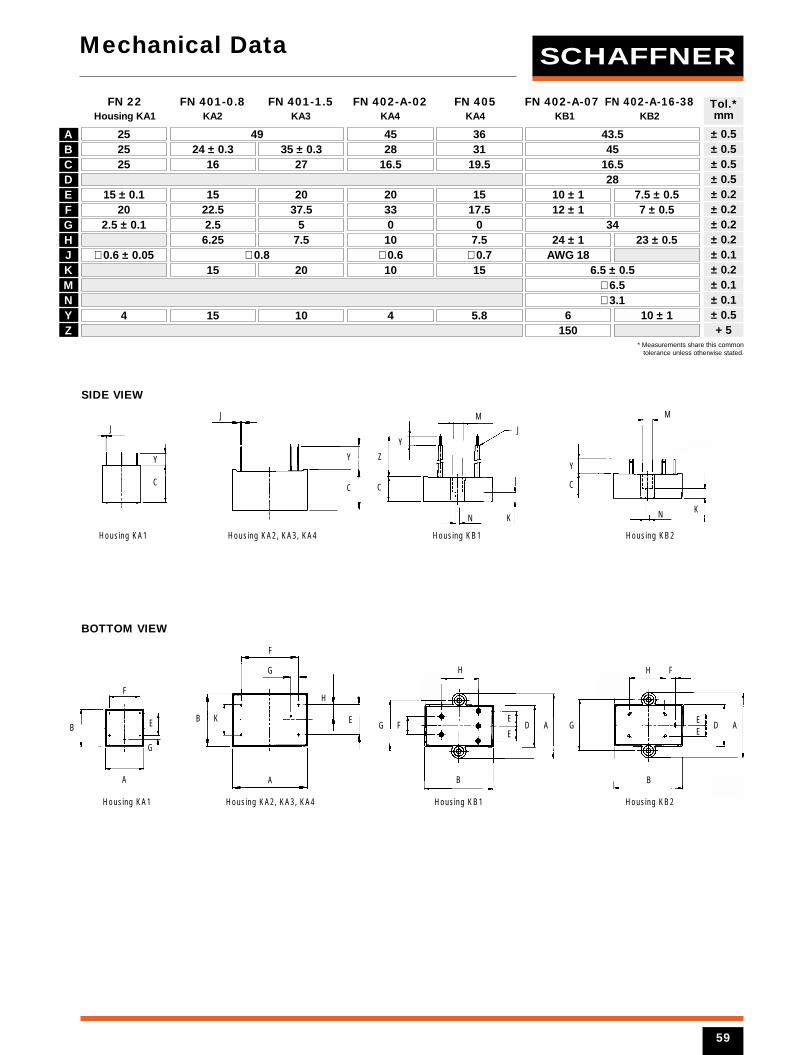
59
Mechanical Data
ABCDEFGHJKMNYZ
25 49 45 43.525 24 ± 0.3 35 ± 0.3 28 4525 16 27 16.5
2815 ± 0.1 15 20 20 10 ± 1 7.5 ± 0.5
20 22.5 37.5 33 12 ± 1 7 ± 0.52.5 ± 0.1 2.5 5 0 34
6.25 7.5 10
15 20 10
24 ± 1 23 ± 0.5∅ 0.6 ± 0.05 ∅ 0.8 ∅ 0.6
4
3631
19.5 16.5
1517.5
07.5
15∅ 0.7
5.8
AWG 186.5 ± 0.5
∅ 6.5∅ 3.1
4 6 10 ± 1150
FN 22 FN 401-0.8 FN 401-1.5 FN 402-A-02 FN 405 FN 402-A-07 FN 402-A-16-38Housing KA1 KA2 KA3 KA4 KA4 KB1 KB2
± 0.5± 0.5± 0.5± 0.5± 0.2± 0.2± 0.2± 0.2± 0.1± 0.2± 0.1± 0.1± 0.5+ 5
Tol.*mm
SIDE VIEW
BOTTOM VIEW
JJ
C
Y
N K
C
Z
YJ
M
Y
C
F
E
A
Housing KA1 Housing KA2, KA3, KA4 Housing KB1 Housing KB2
Housing KA1 Housing KA2, KA3, KA4 Housing KB1 Housing KB2
BE
H
F
H
G F D A
B
H
G
F
E
ED A
EE
B
G
B K
A
M
C
Y
N K
* Measurements share this commontolerance unless otherwise stated.
G
15 10
SCHAFFNER
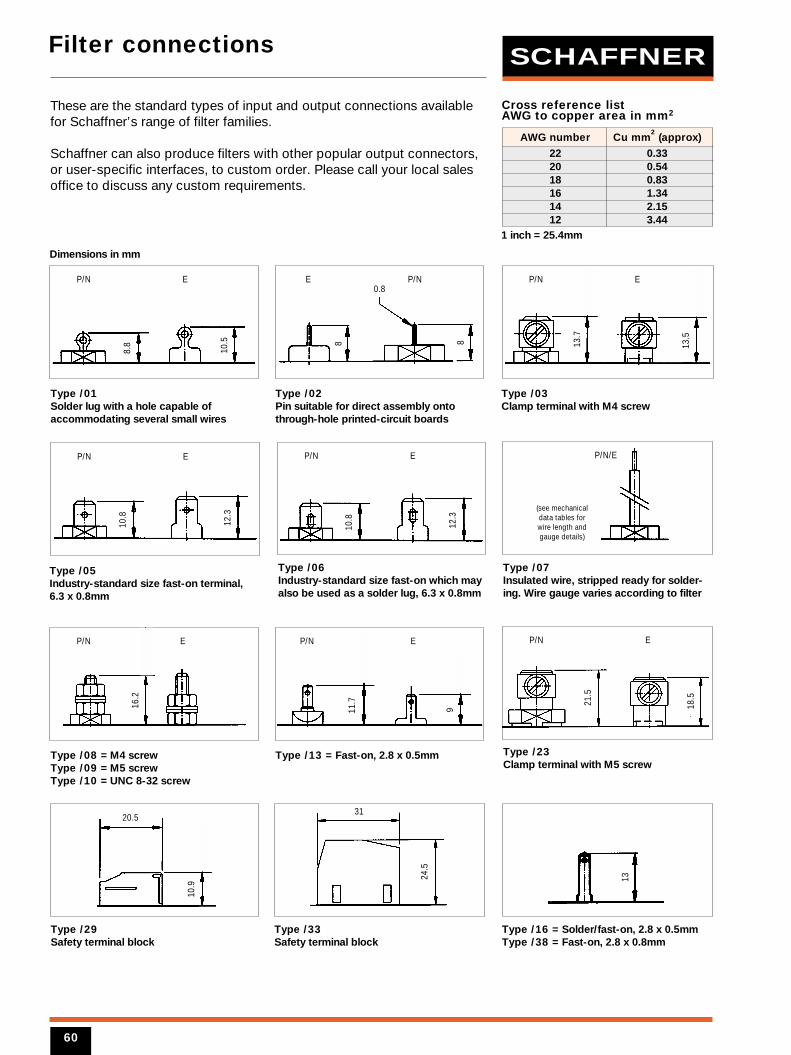
Filter connections
60
These are the standard types of input and output connections availablefor Schaffner’s range of filter families.
Schaffner can also produce filters with other popular output connectors,or user-specific interfaces, to custom order. Please call your local salesoffice to discuss any custom requirements.
Type /01Solder lug with a hole capable ofaccommodating several small wires
Type /02Pin suitable for direct assembly ontothrough-hole printed-circuit boards
Type /03Clamp terminal with M4 screw
Type /06 Industry-standard size fast-on which mayalso be used as a solder lug, 6.3 x 0.8mm
Type /07Insulated wire, stripped ready for solder-ing. Wire gauge varies according to filter
AWG number Cu mm2
(approx)
22 0.3320 0.5418 0.8316 1.3414 2.1512 3.44
1 inch = 25.4mm
Cross reference list AWG to copper area in mm2
8.8
12.3
10.5 13
.7
13.5
8 8
0.8
10.8
P/N E P/NP/N EE
P/N E P/N/E
(see mechanicaldata tables forwire length andgauge details)
Type /08 = M4 screwType /09 = M5 screwType /10 = UNC 8-32 screw
Type /13 = Fast-on, 2.8 x 0.5mm
Type /05Industry-standard size fast-on terminal,6.3 x 0.8mm
Type /23 Clamp terminal with M5 screw
Type /29Safety terminal block
12.3
18.5
10.8
21.5
P/N E
P/N
P/N
E
E P/N E
20.5
Type /33Safety terminal block
24.5
31
Type /16 = Solder/fast-on, 2.8 x 0.5mmType /38 = Fast-on, 2.8 x 0.8mm
13
10.9
11.7
916.2
Dimensions in mm
SCHAFFNER
Schaffner’s worldwide sales,distribution and production networkHEADQUARTERS
Schaffner EMV AGNordstrasse 11CH-4542 LuterbachSwitzerland Tel: (032) 6816 626Fax: (032) 6816 641
EUROLOGISTICS CENTER
Schaffner1A, avenue de SuisseF-68311 IllzachFrance Tel: (03) 89 31 04 00Fax: (03) 89 31 04 01
FACTORIES
Schaffner EMV AGNordstrasse 11CH-4542 LuterbachSwitzerland Tel: (032) 6816 626Fax: (032) 6816 641
Schaffner LtdNational Technological ParkCastletroyLimerickIreland Tel: (061) 332233Fax: (061) 332584
Schaffner EMC Co Ltd67 Moo 4 Tambol Ban KlangAmphur Muang PO Box 14Lamphun 51000ThailandTel: (053) 581 104Fax: (053) 581 019
SALES SUBSIDIARIES
Schaffner Beijing Liaison OfficeRoom 911, Bright China Chang An BuildingNo. 7 Jianguomennei DajieBeijing 100005ChinaTel: (10) 6510 1761Fax: (10) 6510 1763
Schaffner SA43 rue Michel CarréF-95103 ArgenteuilFranceTel: (01) 34 34 30 60Fax: (01) 39 47 02 28
Rhone AlpesF-38560 Champ sur DracTel: (04) 76 68 64 00 Fax: (04) 76 68 63 70
RennesF-35510 Cesson-SévignéTel: (02) 99 22 70 00Fax: (02) 99 22 70 07
Schaffner EMV GmbHSchoemperlenstrasse 12BD-76185 KarlsruheGermany Tel: (0721) 56 910 Fax: (0721) 56 9110
Northern GermanyD-59581 WarsteinTel: (02902) 97 56 10Fax: (02902) 97 56 80
Schaffner EMC SrlVia Galileo Galilei, 47I-20092 Cinisello Balsamo (MI)ItalyTel: (02) 66 04 30 45Fax: (02) 61 23 943
Schaffner EMC KK2-31-6 KamiumaSetagaya-KuTokyo 154-0011JapanTel: (03) 3418 5822 Fax: (03) 3418 3013
Schaffner EMC Pte Ltd1200 Depot Road 06-01Singapore 109675Tel: 377 3283Fax: 377 3281
Schaffner EMC ABTurebergstorg 1,6S-19147 SollentunaSwedenTel: (08) 5792 1121Fax: (08) 929690
Schaffner Altrac AGMühlehaldenstrasse 6CH-8953 DietikonSwitzerland Tel: (01) 744 6111Fax: (01) 744 6161
Schaffner EMC LtdAshville WayMolly Millar’s LaneWokinghamBerks RG41 2PLUKTel: (0118) 9770070Fax: (0118) 9792969
Schaffner EMC Inc9-B Fadem RoadSpringfield, NJ 07081USA Toll free: 800 367 5566Tel: (973) 379 7778 Fax: (973) 379 1151
West CoastIrvine, CA 92718Tel: (949) 457 9400Fax: (949) 457 9510
DISTRIBUTORS
AustriaEurodis Electronics GmbH Tel: 1 610 620
BelgiumSEI Belgium Tel: 2 456 0747
Czech RepublicEnergo Praga Ltd. Tel: 2 6111 2665
DenmarkAvnet Nortec A/S Tel: 44 88 08 00
FinlandElectro Ferrum Oy Tel: 19 326 616
GermanySpoerle Electronic Tel: 6103 3048
GreeceMicrelec Advanced Technologies Ltd. Tel: 1 569 5043
NetherlandsSEI Benelux B.V. Tel: 76 57 22 500
NorwayAvnet Nortec A/S Tel: 66 77 36 00
PolandAstat Sp. Tel: 61 8488 871
SpainSelco S.A. Tel: 91 637 1011
SwedenAvnet Nortec AB Tel: 8 629 1400
TurkeyArtest Elektronik Tel: 216 478 1757
AustraliaWestek Industrial Products Pty Ltd. Tel: 3 9369 8802
BrasilTeknikao Ind e Com Ltda Tel: 11 3901 3741
Hong KongDenetron International Ltd. Tel: 2 707 9132
IndiaVishal Agencies Tel: 40 711 2079
IsraelRDT Components Ltd. Tel: 3 645 0707
JapanNemic Lambda K.K. Tel: 3 3447 4411SSR Engineering Co. Ltd. Tel: 3 3493 6613Unidux Inc Tel: 4 2232 4500
KoreaPower EMC TEK Tel: 2 501 5852
New ZealandMHS Technologies Ltd. Tel: 4 567 7016
Republic of South AfricaArrow Altech Ltd. Tel: 11 923 9600
TaiwanBandtek International Co. Ltd. Tel: 2 2657 2615
SCHAFFNER
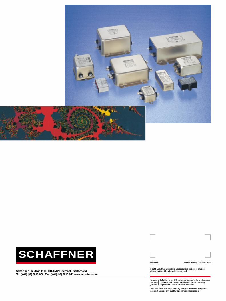
Schaffner Elektronik AG CH-4542 Luterbach, SwitzerlandTel: [+41] (32) 6816 626 Fax: [+41] (32) 6816 641 www.schaffner.com
690-339H Benteli Hallwag/October 1998
© 1995 Schaffner Elektronik. Specifications subject to changewithout notice. All trademarks recognised.
Schaffner is an ISO-registered company. Its products aredesigned and manufactured under the strict qualityrequirements of the ISO 9001 standard.
CertifiedISO 9001
supplier
This document has been carefully checked. However, Schaffnerdoes not assume any liability for errors or inaccuracies.
SCHAFFNER