Embed Size (px)
Citation preview

The International Journal of Nautical Archaeology and Underwater Exploration (1978). 7.1 :29-58
The Dartmouth, a British frigate wrecked off Mull, 1690 5. The ship
Colin J. M. Martin Institute of Maritime Archaeology, University of St Andrews, Fife (in association with the Under- sea Archaeology Branch (Bristol), BSAC)
Investigation of the wreck of HMS Dartmouth, a fifth rate warship['] lost in the Sound of Mull in 1690, has already led to a number of special- ist studies (Adnams, 1974; Holman, 1975; McBride, 1976; P. Martin, 1977). Since its dis- covery in 1973 a total of 24 weeks of fieldwork has been completed on the site by the Institute of Maritime Archaeology, working in conjunction with the Bristol Undersea Archaeology Branch of the British Sub-Aqua Club. In this work the Institute's primary concern has been with the isolation and recording of the structural remains of the ship, and with interpreting the wreck formation as a whole. Though some peripheral areas of the site remain unexcavated it is now believed that the full extent of the surviving structure has been defined, and it is the aim of
this paper to describe and discuss these re- mains.
The ship The Dartmouth was completed at Portsmouth by John Tippets in 1655 to the following specification (Anon, 1689): Length by the keel 80 ft (24.4 m)[2 Breadth by the beam 25 ft (7-6 m) Depth in hold 10 ft (3.05 m) Draught 12 ft (3.66 m) Tuns burden 2 66
Her armament, as listed in the Ordnance Office Establishment of 1687 (McBride, 1976) was as follows: Demi-culverin drakes (9-pounders) 16
Figure 1. A fifth-rate, probably the Dartmouth, sketched by Van de Velde in the 1670s. Photo by courtesy of the National Maritime Museum.
29

NAUTICAL ARCHAEOLOGY, 7.1
Saker drakes (6-pounders) 16 Minion forts (3-pounders) 4
Sir John Tippets, who became Surveyor of the Navy in 1672, had studied ship design and construction in Denmark as a young man dur- ing the reign of Charles I (Pepys’sNavaZMinutes, 1926: 223). In the 1640s radical developments had taken place in the design of small British warships, and in 1646 the first of the so-called ‘frigates’, the Constant Warwick, was built in Pett’s yard at Ratcliffe (Pepys’s Naval Minutes, 1926: 15). The hull form of the Constant War- wick, according to Pepys, was ‘taken from the
Dunkirk frigates, which outsailed all other ships in the seas; and from thence came that improve- ment. Upon which foundation our frigates from the third rate downwards were built’.
Tippets-who was to rebuild the Constant Warwick in 1666-thus learned his trade as a shipwright against a background of and in inti- mate contact with a new design concept which produced manoeuverable and fast vessels by combining lightness with fine underwater lines. We may suppose that these influences were strong in his mind when, less than a decade after the Constant Warwick had been launched,
T A B L E OF L O R N
wreck
c . , r . , c
r
@a Glas Eileanan
Gobhar
Rubha an Ridire
I 1 0 1 nautical mi le
Figure 2. The south-east end of the Sound of Mull, showing the Dartmouth’s wreck site and earlier anchorage.
30

C. J. M. MARTIN: THE DARTMOUTH
he laid down Dartmouth’s keel. A fine impres- sion of the sleek light hull of this class of vessel is conveyed in Van de Velde’s mid 1670s sketch of a fifth rate (Fig. l ) , thought to represent the Dartmouth herself (Robinson, 1958: 164 and 362). The ship’s long service career in many parts of the world, often involving operations in confined and difficult waters, further points to her excellent sailing qualities and design.
In 1678 the ship underwent a major overhaul, which included the fitting of a new keel. An itemized account of this refit and two succeed- ing surveys, which provide much technical information about the construction of the ship and are consequently of value in interpreting the archaeological remains, are included in a prdcis as an Appendix to this paper.
The wrecking In October 1690, Dartmouth, under the com- mand of Captain Edward Pottinger and in company with two smaller ships, entered the Sound of Mull in order to persuade, by force if need be, the Jacobite MacLean of Duart to sign Articles of Allegiance to William and Mary. This small squadron had been based at Greenock since March with the object of demonstrating the authority of the new regime on the west coast of Scotland, and of supporting govern- ment land forces operating there. These ex- tended patrol duties had placed a heavy strain on the serviceability of the ships and their equipment, and on 2 December Captain Pottinger, writing from the Ardgour Channel at the head of Loch Linnhe, noted ‘our best bower cable, with often anchoring . . . is so extremely worn as not to be trusted’ (PRO ADM 106/399).
As the ships sailed down the Sound from the north-west bad weather threatened, and a pre- cautionary anchorage was made in Scallastle Bay, some five miles short of Duart. This spot is still noted on Admiralty Chart 2390 (1976) as an emergency anchorage. At 18.00 hrs on 9 October a violent storm parted Dartmouth from her anchors and drove the ship across the Sound to strike a rocky islet and become a total loss (Fig. 2). Of the 130 or so on board only six survived (Adnams, 1974).
Traditional accounts A tradition of the Dartmouth wreck has sur-
vived on Mull into the present day, although perhaps inevitably it is confused in parts with the more famous Tobermory wreck of a cen- tury earlier. A version of the story was told to me by Mr Willie Fletcher of Loch Don, who is 71 years old and first heard the story himself when he was 14 from a woman then aged 80. This tradition attributes the loss of the ship to Jacobite-inspired witchcraft, and relates the spell which supposedly caused the wreck. A rope was tied through the centre of a heavy millstone, and then used to pull the millstone over a rafter, so causing the warship anchored in the bay to capsize and sink. The analogy of the toppling millstone and the capsizing ship is particularly vivid in the story, and stress is laid on the considerable effort needed by the witches to pull the heavy and awkwardly balanced stone over the rafter-several times it almost came over but fell back, and several times the ship heeled critically in the gale but then righted herself. It seems likely that this precise and graphic description of the vessel’s behaviour in the storm derives from an eye witness account of what actually happened.
Another version of the story, which differs sufficiently in detail not to be itself the source of Mr Fletcher’s account, was published nearly a century ago (Lorne, 1898: 187-91). This version states that ‘for two days it blew very hard, and the ship’s anchors held during that time; but on the third day the wind was so violent that some of the cables gave way, and she drifted, pulling the anchors after her. And away she went, stern foremost, until she struck the Knight’s Point in Morvern, across the Sound. The waves beat on her until she went to pieces there, to the great rejoicing of the MacLeans’.
Until at least the mid-19th century the site of the disaster was remembered locally. McLeod (1867: 239), states that the vessel ‘was wrecked on a rock opposite Duart, and only a few years ago the spot was examined. . . when human remains were discovered. Some of the guns of the vessel have also, I believe, been seen’.
From these accounts it appears that the ship was at least partially capsized when she was driven, stern first, a distance of some two miles (3-2 km) from her anchorage to the north- western end of the islet of Eilean Rubha an
31

NAUTICAL ARCHAEOLOGY, 7.1
a
' , fi
.... -
E
".,
32

C. J. M. MARTIN: THIS DARTMOUTH
Ridire, close to the Morvern shore, where her wreck was located in 1973 (Adnams, 1974) (Fig. 2).
The wreck formation: description and inter- pretation Before examining the structural evidence it is necessary to consider the wreck formation as a whole-that is, the relationship between the coherent ship, the environmental factors affect- ing its wrecking and deposition, and the re- mains as they now appear.
The north-western face of Eilean Rubha an Ridire has collected at least two wrecks subse- quent to that of the Dartmouth. The most recent, that of the coaster Ballista which was lost in 1973, overlies the remains of a coal- carrying vessel of the 1940s. Fortunately the Dartnzouth site is little polluted with material from the modern wrecks because of a rock spur which separates them from it. Such intrusive material as there is has generally been easy to spot: in addition to some pieces of iron, a broken gramophone record, and a quantity of coal, patently originating from the modern wrecks, some 19th century artefacts have been noted, including a heavy calibre lead rifle bullet of early type and a quantity of bottle glass. The latter no doubt derives from the debris of island picnics which, from Victorian times, have been popular; the former perhaps from stag or seal hunting of similar date.
Though a steady tidal stream runs across the northern side of the islet from north-east to south-west, the site itself is largely free from currents. It is also reasonably well protected from heavy seas, and although it can be ex- posed to a fairly violent chop in north-westerly winds, the maximum open water fetch of 11 miles (17.7 km) is insufficient for major swells to develop. The stability of the seabed is enhanced by a luxuriant coverage of Laminaria digitQta:
The wreck lies at the foot of a sloping rock face hard against the side of the island (Fig. 3). At the shoreward end wreckage is contained within a wedge-shaped gully only 8 to 10 ft (2.44 to 3.05 m) deep at Low Water Springs, and one gun (20) lies close to the apex of this gully at an even shallower depth. Another gun (2) lies partly up-ended in a rock cleft nearby,
while three more (1, 3 and 5) were noted close to the base of the northern rock face.
Excavation of the shoreward end of the wreckage has yielded a group of artefacts clearly associated with the after end of the ship. These include navigational and surgical instruments, a sea-service flintlock pistol, balance weights, and fine pewter and ceramic tableware. Leaded mica pieces (Fig. 4) were also found in this area. These more probably come from the windows of the great cabin or the bulkheads of officers’ cabins than from the lantern, since a large group of lantern mica pieces found recently during the excavation of the 17th century levels at Woolwich Dockyard (Courtney, 1975: 48-50) were bound not with lead but with strips of zinc coated iron, appar- ently to withstand the heat of the lamp. In either event they are to be securely placed in the stern. ‘Muscovy glass’ (i.e. mica) is men- tioned in the ship’s 1678 refit (see Appendix), and was apparently used as a glazing material in the Royal Navy until 1704, when it was replaced by glass (Courtney, 1975: 49).
The artefactual evidence thus supports the traditional account that the ship struck stern first, and this is further confirmed by comple- mentary evidence from the other end of the site, discussed below.
The main spread of coherent structure begins where the mouth of the gully starts to widen out, and slopes gradually seawards, following the rock base for some 40 ft (12.19 m) until it reaches a depth of 17 ft (5.18 m). About 18 ft (5.49 m) of the keel survives at the inshore end.
Before excavation the timber structure was covered with up to 2 ft (0.61 m) of shingle and boulders which had presumably tumbled from the slope above, and was further pinned and preserved by several large iron concretions which included guns, shot, and a 13 ft (3.96 m) anchor. That at least some of this material was ballast is suggested by the number of broken guns in this area (4, 6 , 7, 8, and 10, and other gun fragments observed within the concretion but not removed from it), by the presence of shot too large to fit any of the Dartmouth’s listed or identified armament (including 6 in (0.152 m) balls, nominally 32-pounders), and by considerable quantities of flint chippings which presumably derive from the ship’s ballast gravel.
33

NAUTICAL ARCHAEOLOGY, 7.1
There are several references to the Dart- mouth’s ballast in documentary sources (PRO ADM 106/399; 51/3819). A letter from Cap- tain Pottinger dated 30 July 1690 at Greenock records that four days earlier the ship had been emptied of guns and ballast and laid ashore, and that she was now ‘again afloat: our guns, pow- der, ballast, etc. aboard’. This seems to suggest that the ballast was put back after repairs and cleaning were complete, and does not imply fresh material. We may infer that new ballast had been stowed some months before, since on 7 November 1689 William Kiggins, Dartmouth’s lieutenant, had written from Hoylake, Cheshire, that ‘our ship’s company is sickly, one great occasion of it is, our ballast being so bad, stink- ing and all of a quagmire, and sandy that it stoaks the limbers, that the water has no course to the pump. Had we that ballast out, and shingle in, I doubt not but our ship would be healthy, and in good condition’. This sorry
state of affairs would surely have been set to rights during January 1690 when, for the whole of that month, the ship lay at Plymouth refit- ting. We may suppose that the ‘stinking quag- mire’ was dumped, the hull thoroughly rummaged, and clean shingle stowed.
This new ballast may well have been the ballast she was carrying when, nine months later, she was wrecked. Certainly flint-bearing gravel would have been readily available at Plymouth, while it does not occur naturally either at Greenock or in the Sound of Mull. It is not therefore unreasonable to see in the flint pieces scattered over the wreck site an accurate indicator of ballast spread from the ship.
Iron ballast was often used in conjunction with gravel since it was a more convenient material with which to adjust trim. Several references in the Dartmouth’s log mention such ballast. On 30 May 1678, for example, she ‘took in 15 tuns of ballast which completes the
Figure 4. Leaded mica pieces from the stern glazing (scale in millimetres). Photo by courtesy of the National Museum of Antiquities of Scotland.
34
C. J. M. MARTIN: THE DARTMOUTH
70 tuns we had before, of which 15 tuns or thereabouts is old iron’. Again, on 19 May 1683, the ship ‘got aboard broken shells and guns for dead ballast’, while on the following day she received ‘ a gun weighing 45 cwt 3 qtrs 11 lbs for ballast’. In the hexhedral-shaped masses of ‘old iron’ identified on the wreck site, particu- larly the lump weighing an estimated 3 tons of which the broken gun 8 is a part, we may surely recognize closely packed piles of such ballast, no doubt once securely boxed with shifting boards into an appropriate part of the hold.
Between the western end of the coherent structure and the curve inwards of the cliff towards the north-west-a distance of some 30 ft (9.14 m)-excavation revealed a gravelly deposit up to 2 ft (0.61 m) deep which overlay bedrock close to the cliff and a firm clay/pebble conglomerate elsewhere. This deposit contained a quantity of scattered timber, most of which could be recognized either as elm planking or fir sheathing. Throughout this area the charac- teristic ballast flints were noted, and in the western two-thirds of it objects of a kind to be associated with a bosun’s store were found in some quantity. These consisted of rigging fit- tings of various types, including cordage, parrel and shroud trucks, deadeyes, blocks of differ- ent sizes, and several loose sheaves. Some of these fittings showed evidence of makeshift repair, while others by their lack of running wear had clearly never been used. The bosun’s locker, where new rigging fittings were stored and unserviceable ones repaired, is traditionally located in the fore part of the ship, and parallel examples may be cited archaeologically from the Amsterdam (Marsden, 1974: 153-5) and historically from Chapman’s sectional drawing of a mid-18th century privateer (Chapman, 1768: pl. XXXII). This part of the wreck also contained concretions of what had once been boxes or kegs of hand grenades together with large quantities of lead shot of pistol and musket calibre (McBride, 1976: 196-9). These finds appear to indicate the presence of an armoury, a conclusion supported by the discovery in the same area of a Highland musket stock. Like the bosun’s locker the ship’s armoury, especially in small vessels, was generally situated well for- ward. This evidence, when coupled with the evi- dence relating to the stern discussed above,
makes it clear that the main axis of the wreck runs, through the surviving keel, approximately east-north-east-west-south-west with the stern lying towards the east and the bow towards the west.
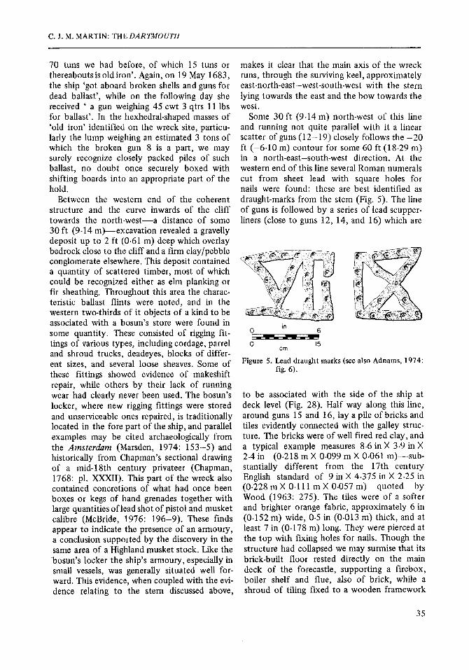
Some 30f t (9.14m) north-west of this line and running not quite parallel with it a linear scatter of guns (12-19) closely follows the -20 ft (-6.10 m) contour for some 60 ft (18.29 m) in a north-east-south-west direction. At the western end of this line several Roman numerals cut from sheet lead with square holes for nails were found: these are best identified as draught-marks from the stem (Fig. 5). The line of guns is followed by a series of lead scupper- liners (close to guns 12, 14, and 16) which are
6 in 0 -
15 cm
Figure 5. Lead draught marks (see also Adnams, 1974; fig. 6 ) .
to be associated with the side of the ship at deck level (Fig. 28). Half way along this line, around guns 15 and 16, lay a pile of bricks and tiles evidently connected with the galley struc- ture. The bricks were of well fired red clay, and a typical example measures 8.6 in X 3.9 in X 2-4 in (0.218 m X 0.099 m X 0.061 m)-sub- stantially different from the 17th century Enghsh standard of 9 in X 4.375 in X 2.25 in (0.228 m X 0.1 11 m X 0.057 m) quoted by Wood (1963: 275). The tiles were of a softer and brighter orange fabric, approximately 6 in (0.152 m) wide, 0.5 in (0.013 m) thick, and at least 7 in (0.178 m) long. They were pierced at the top with fixing holes for nails. Though the structure had collapsed we may surmise that its brick-built floor rested directly on the main deck of the forecastle, supporting a firebox, boiler shelf and flue, also of brick, while a shroud of tiling fured to a wooden framework
35
NAUTICAL ARCHAEOLOGY, 7.1
r
~~~
SYMBOLS
A gold/ silver
A other non-ferrous
clay tobacco pipes pottery
o glass
0 organic
@& concretion
--+
-+
0
OA
A $$ A &
, o
0
0 A A A
t- qrenades --+ - 0 3 metres
4- musket shot -b
4 scattered flints +
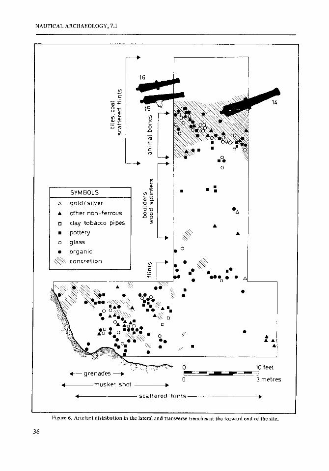
Figure 6. Artefact distribution in the lateral and transverse trenches at the forward end of the site.
36

C. J. M. MARTIN: THE DAR TMOUTH
above it helped to reduce the hazard of acci- dental fire (cf. the ‘lining of the beams and planks over the firehearth’ of the 1678 refit). Possibly the slates reported by Adnams (1974: fig. 7) were also connected with this protective shroud.
Among the remains of the galley were found considerable quantities of burnt debris, animal bones, and coal. The latter was firmly associ- ated with wreck levels and concretion, and therefore unconnected with surface coal from the modern collier wreck. Coal would have been readily available in late 17th century Greenock from the open-cast delvings around Glasgow, and would have provided the Dart- mouth with an excellent source of galley fuel.
A length of narrow-bore lead piping flanged at one end and pinned beneath gun 15 at the other may have been associated with the plumb- ing of the boiler (thls pipe unfortunately dis- appeared from the site shortly after the wreck’s discovery was announced). The ship’s watch bell, which would have hungin a belfry immedi- ately above the galley on top of the forecastle (it may be seen, without a bell, in Fig. l), was found concreted to the side of gun 15.
Twenty feet (6.10m) west of the forward end of the line of guns lay a pair of medium-
sized anchors, 7 and 8 ft (2.13 and 2.44m) long, nestled crown to ring as if stowed and lashed when lost. Close by was a piece of lead sheeting and a large-bore lead pipe flanged at either end (Fig. 28), perhaps associated with the sanitary arrangements of the heads (cf. the leaden ‘pissdale pipes’ of the 1678 refit).
A lateral trench, 10 ft (3.05 m) wide, was driven from just forward of the coherent struc- ture towards the line of guns and scupper liners in the vicinity of the galley remains, in order to determine the relationship between the two main axes of the wreck (Fig. 6). Once again a deposit of loose stones and gravel some 18 in (0.46 m) deep was found to overlie a firm clay/ pebble substratum, which evidently represented a natural level beyond which wreck material had not penetrated, although some heavy objects had partially indented its surface (Fig. 7). The top deposit was cleared down to this substratum to reveal a distribution of artefacts shown diagrammatically in Fig. 6.
The pattern shown in this distribution is note- worthy. Between the two axes there is a remark- able paucity of objects of any kind until a point some 6 ft (1.83 m) from the line of guns is reached. Beyond this, and up to the line, numerous artefacts of all kinds are crowded
Figure 7. Lead scupper-liner in situ, partially embedded in the top level of the claylpebble substratum. Scale 1 ft.
37
NAUTICAL ARCHAEOLOGY, 7.1
\ SECTION AT R4 ' port
\ \ \
starboard -
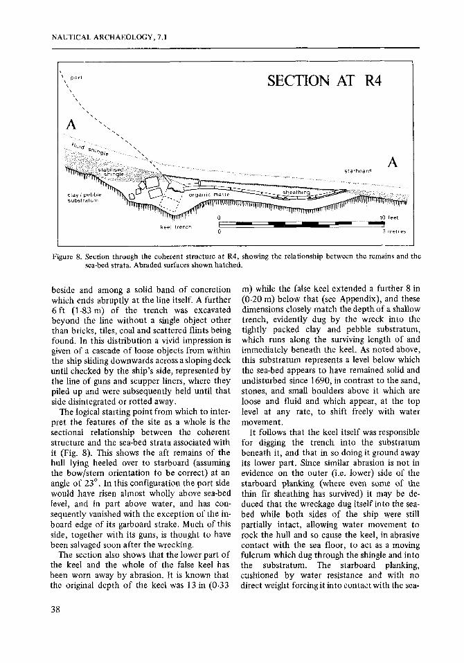
Figure 8. Section through the coherent structure a t R4, showing the relationship between the remains and the sea-bed strata. Abraded surfaces shown hatched.
beside and among a solid band of concretion which ends abruptly at the line itself. A further 6 ft (1.83 m) of the trench was excavated beyond the line without a single object other than bricks, tiles, coal and scattered flints being found. In this distribution a vivid impression is given of a cascade of loose objects from within the ship sliding downwards across a sloping deck until checked by the ship's side, represented by the line of guns and scupper liners, where they piled up and were subsequently held until that side disintegrated or rotted away.
The logical starting point from which to inter- pret the features of the site as a whole is the sectional relationship between the coherent structure and the sea-bed strata associated with it (Fig. 8). This shows the aft remains of the hull lying heeled over to starboard (assuming the bow/stern orientation to be correct) at an angle of 23'. In this configuration the port side would have risen almost wholly above sea-bed level, and in part above water, and has con- sequently vanished with the exception of the in- board edge of its garboard strake. Much of this side, together with its guns, is thought to have been salvaged soon after the wrecking.
The section also shows that the lower part of the keel and the whole of the false keel has been worn away by abrasion. It is known that the original depth of the keel was 13 in (0.33
m) while the false keel extended a further 8 in (0.20 m) below that (see Appendix), and these dimensions closely match the depth of a shallow trench, evidently dug by the wreck into the tightly packed clay and pebble substratum, which runs along the surviving length of and immediately beneath the keel. As noted above, this substratum represents a level below which the sea-bed appears to have remained solid and undisturbed since 1690, in contrast to the sand, stones, and small boulders above it which are loose and fluid and which appear, at the top level at any rate, to shift freely with water movement.
It follows that the keel itself was responsible for digging the trench into the substratum beneath it, and that in so doing it ground away its lower part. Since similar abrasion is not in evidence on the outer (i.e. lower) side of the starboard planking (where even some of the thin fir sheathing has survived) it may be de- duced that the wreckage dug itself into the sea- bed while both sides of the ship were still partially intact, allowing water movement to rock the hull and so cause the keel, in abrasive contact with the sea floor, to act as a moving fulcrum which dug through the shingle and into the substratum. The starboard planking, cushioned by water resistance and with no direct weight forcingit into contact with the sea-
38
C . J. M. MARTIN: THE DARTMOUTH
bed as the hull rocked, would have gently fanned away the shingle beneath it to form the hollow into which it eventually settled with minimal damage to its outer surface.
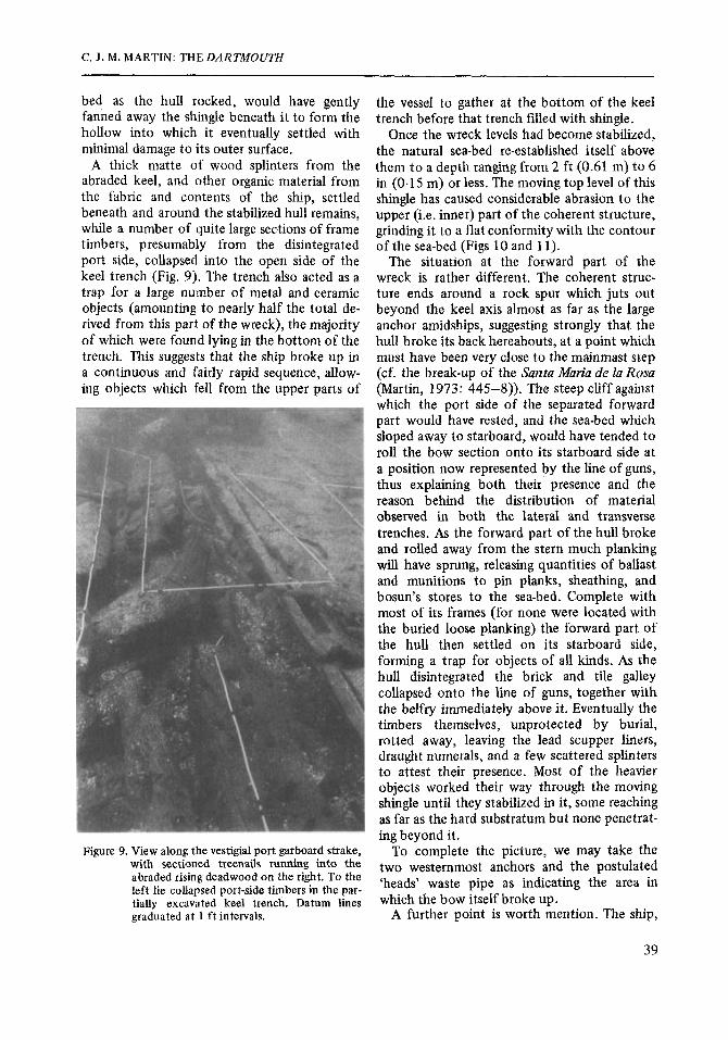
A thick matte of wood splinters from the abraded keel, and other organic material from the fabric and coritents of the ship, settled beneath and around the stabilized hull remains, while a number of quite large sections of frame timbers, presumably from the disintegrated port side, collapsed into the open side of the keel trench (Fig. 9). The trench also acted as a trap for a large number of metal and ceramic objects (amounting to nearly half the total de- rived from this part of the wreck), the majority of which were found lying in the bottom of the trench. This suggests that the ship broke up in a continuous and fairly rapid sequence, allow- ing objects which fell from the upper parts of
Figure 9. View along the vestigial port garboard strake, with sectioned treenails running into the abraded rising deadwood on the right. To the left lie collapsed port-side timbers in the par- tially excavated keel trench. Datum lines graduated a t 1 ft intervals.
~ ~-~
the vessel to gather at the bottom of the keel trench before that trench filled with shingle.
Once the wreck levels had become stabilized, the natural sea-bed re-established itself above them to a depth ranging from 2 ft (0.61 m) to 6 in (0.15 m) or less. The moving top level of this shingle has caused considerable abrasion to the upper (i.e. inner) part of the coherent structure, grinding it to a flat conformity with the contour of the sea-bed (Figs 10 and 11).
The situation at the forward part of the wreck is rather different. The coherent struc- ture ends around a rock spur which juts out beyond the keel axis almost as far as the large anchor amidships, suggesting strongly that the hull broke its back hereabouts, at a point which must have been very close to the mainmast step (cf. the break-up of the Santa Maria de la Rosa (Martin, 1973: 445-8)). The steep cliff against which the port side of the separated forward part would have rested, and the sea-bed which sloped away to starboard, would have tended to roll the bow section onto its starboard side at a position now represented by the line of guns, thus explaining both their presence and the reason behind the distribution of material observed in both the lateral and transverse trenches. As the forward part of the hull broke and rolled away from the stern much planking will have sprung, releasing quantities of ballast and munitions to pin planks, sheathing, and bosun’s stores to the sea-bed. Complete with most of its frames (for none were located with the buried loose planking) the forward part of the hull then settled on its starboard side, forming a trap for objects of all kinds. As the hull disintegrated the brick and tile galley collapsed onto the line of guns, together with the belfry immediately above it. Eventually the timbers themselves, unprotected by burial, rotted away, leaving the lead scupper liners, draught numerals, and a few scattered splinters to attest their presence. Most of the heavier objects worked their way through the moving shingle until they stabilized in it, some reaching as far as the hard substratum but none penetrat- ing beyond it.
To complete the picture, we may take the two westernmost anchors and the postulated ‘heads’ waste pipe as indicating the area in which the bow itself broke up.
A further point is worth mention. The ship,
39

NAUTICAL ARCHAEOLOGY, 7.1
when lost, still had at least three anchors on board-two apparently stowed and lashed near the bow and one, the largest, midships inside the hull. For a ship to leave anchors aboard when in dire peril of wrecking on a lee shore seems extraordinary. Even allowing a surface drift of up to ten knots there will have been a lapse of at least ten minutes from breaking adrift to striking, time enough for seamen of Dartmouth’s calibre to loose the forward anchors or even bring up, stock and cast the big anchor stowed below-probably her sheet anchor, the anchora spei normally kept un- stocked iii the hold and reserved for the last extremity (Mainwaring, c. 1623: 89). This failure might be explained by a lack of cables, but this is unlikely, since although Captain Pottinger had complained about the condition of his best bower cable a month before the wreck he made no mention of a lack of cables
for his spare anchors, which would surely have been just as serious a matter. Much more prob- ably, the final wrecking on Eilean Rubha an Ridire was the culmination of a series of disas- ters which prevented such obvious measures from being taken, and the start of this fatal chain of events may well have been the over- setting of the ship when the cables parted in Scallastle Bay, as is so vividly implied in the toppling millstone analogy of the traditional story. In short, the archaeological evidence firmly supports the evidence of the folk accounts, in that both imply that after striking the islet stern first and on her beam ends the waves beat on the ship ‘until she went to pieces there, to the great rejoicing of the Machans’.
The hull remains Methods of recording The full extent of the coherent structure was
Figure 10. Abraded frames 3 and 4, viewed from the starboard side looking inboard. Note how abrasion has re- duced their vertical height almost to extinction. These are the forwardmost frames to butt into the rising deadwood; succeeding ones are clamped beneath it. Scale graduations in feet.
40
C. J. M. MARTIN: THE DARTMOUTH
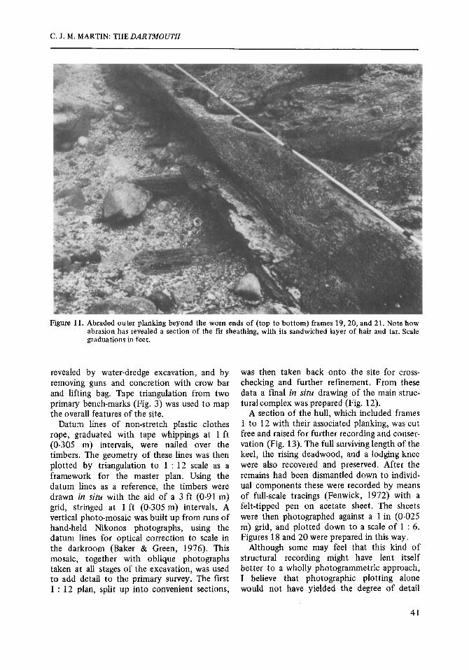
Figure 11. Abraded outer planking beyond the worn ends of (top to bottom) frames 19, 20, and 21. Note how abrasion has revealed a section of the fir sheathing, with its sandwiched layer of hair and tar. Scale graduations in feet.
revealed by water-dredge excavation, and by removing guns and concretion with crow bar and lifting bag. Tape triangulation from two primary bench-marks (Fig. 3) was used to map the overall features of the site.
Datum lines of non-stretch plastic clothes rope, graduated with tape whippings at 1 ft (0-305 m) intervals, were nailed over the timbers. The geometry of these lines was then plotted by triangulation to 1 : 12 scale as a framework for the master plan. Using the datum lines as a reference, the timbers were drawn in situ with the aid of a 3 ft (0.91 m) grid, stringed at 1 ft (0.305 m) intervals. A vertical photo-mosaic was built up from runs of hand-held Nikonos photographs, using the datum lines for optical correction to scale in the darkroom (Baker & Green, 1976). This mosaic, together with oblique photographs taken at all stages of the excavation, was used to add detail to the primary survey. The first 1 : 12 plan, split up into convenient sections,
was then taken back onto the site for cross- checking and further refinement. From these data a final in situ drawing of the main struc- tural complex was prepared (Fig. 12).
A section of the hull, which included frames 1 to 12 with their associated planking, was cut free and raised for further recording and conser- vation (Fig. 13). The full surviving length of the keel, the rising deadwood, and a lodging knee were also recovered and preserved. After the remains had been dismantled down to individ- ual components these were recorded by means of full-scale tracings (Fenwick, 1972) with a felt-tipped pen on acetate sheet. The sheets were then photographed against a 1 in (0.025 m) grid, and plotted down to a scale of 1 : 6. Figures 18 and 20 were prepared in this way.
Although some may feel that this kind of structural recording might have lent itself better to a wholly photogrammetric approach, I believe that photographic plotting alone would not have yielded the degree of detail
41

NAUTICAL ARCHAEOLOGY, 7.1
Figure 13. The main recovered section of hull being dismantled at the Research laboratory of the National Museum of Antiquities of Scotland.
and understanding ultimately derived from the intensive physical exercise of observing and recording the remains in situ over a substantial period. Such an approach, in my opinion, brings the archaeologist into direct and tactile contact with his material in its context, so inducing a sympathy between the three dimensional evi- dence in its actuality, and the interpretation through recording of that evidence. Purely mech- anical techniques, by their very speed and effici- ency, tend to minimize this contact. For precisely the same reason I suspect that attempts by non-diving archaelologists to interpret sub- merged wreck sites are of little value: by its nature archaeological evidence cannot properly be understood at second hand.
The keel (Figs 14 to 16) Because of the absence of the port side and the peculiar arrangement of the frames and rising deadwood (see below) the surviving 18 ft (5.49 m) length of keel was removed from the structure without difficulty. It was made of elm
and, as described above, had been much abraded on its underside. The top part, however, which had been protected by the deadwood and by the two garboard strakes, was in fine condition, revealing clear tool marks on its surfaces and traces of the white paying stuff (apparently white lead and oil) which had been applied where two faces made contact. It had been bolted through to the deadwood with 1 in (0.025 m) collared iron bolts at intervals of approximately 2 ft (0.61 m), the bolt holes being staggered slightly to avoid weakening the grain of the keel. The garboard rebates (Fig. 14) were neatly cut and well caulked with oakum, tar and resin, recalling Sir Henry Mainwaring’s caution that the garboard strake was ‘the most dangerous place in all the ship to spring a leak, for it is almost impossible to come to it within- board’ (Mainwaring, c. 1623: 154). The width of the keel, 13 in (0-33 m), is exactly the dimen- sion given in the 1678 refit (see Appendix), and we may presume that the other measurements given there are correct-namely a depth of 13
42
C. J. M. MARTIN: THE DARTMOUTH
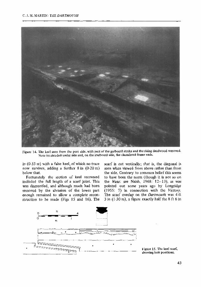
Figure 14. The keel seen from the port side, with part of the garboard strake and the rising deadwood removed. Note its abraded under side and, on the starboard side, the chamfered frame ends.
in (0.33 m) with a false keel, of which no trace now survives, adding a further 8 in (0.20m) below that.
Fortunately the section of keel recovered included the full length of a scarf joint. This was dismantled, and although much had been removed by the abrasion of the lower part enough remained to allow a complete recon- struction to be made (Figs 15 and 16). The
scarf is cut vertically; that is, the diagonal is seen when viewed from above rather than from the side. Contrary to common belief this seems to have been the norm (though it is not so on the Wasa: see Naish, 1968: 12-13), as was pointed out some years ago by Longridge (1955: 7) in connection with the Victory. The scarf overlap on the Dartmoufh was 4 ft 3 in (1 -30 m), a figure exactly half the 8 ft 6 in
43

NAUTICAL ARCHAEOLOGY, 7.1
I /
(2.59 m) excess over the ship’s 80 ft (24.38 m) stem to stern length given for keel timbers in the 1678 re-keeling account, showing that two complete scarfs were allowed for. A three-piece keel would call for sections (measured from the butt-ends of the scarfs) averaging 29 ft 6 i n (8-99 m) apiece, which is close to the maximum length in which elm of this thickness can con- veniently be obtained (Longridge, 1955: 7). If we assume, as is probable, that the three sec- tions were of equal length, the scarf gives us a fixed point on the longitudinal axis of the vessel, and thus we may say, with reasonable confidence, that the forward edge of frame 1 (as numbered in Fig. 12) is 26 ft 8 in (8-12 m) forward of the stern end of the keel.
The scarf is locked vertically by a tabled joint cut from the solid with considerable skill, and horizontally by eight 1 in collared iron bolts. The joint itself was caulked with resin in the tabling, hair and tar along the flat faces, and oakum at the fore and aft butts. Further sealing was effected by a lightly nailed capping piece recessed into the top surface of the joint which held in place a felting of hair and tar.
These remains are undoubtedly those of the 1678 keel, fitted at Captain Castle’s Dock at Rotherhithe. Re-keeling a ship of the Dart- mouth’s size must have been an extraordinarily difficult operation, as she would require laying over with all her weight on one side. Without a keel her frames could hardly have borne this stress on dry land, and it is more likely that
Figure 16. An exploded reconstruction of the keel scarf.
she was careened for the job in the manner shown in a photograph of the re-keeling of the late 19th century schooner Dizzy Dunlop (Eames, 1973: 222-3; 230).
Rising deadwood (Fig. 17) Above the keel, and in flat contact with its upper surface, lay an elm component of massive
Rider
Rising
Forword of frame 5 H
U
Rider
Rising
A f t of frame 5
Figure 17. Suggested arrangements of the lower frame sections fore and aft of frame 5.
44
C. J . M. MARTIN: THE DARTMOUTH
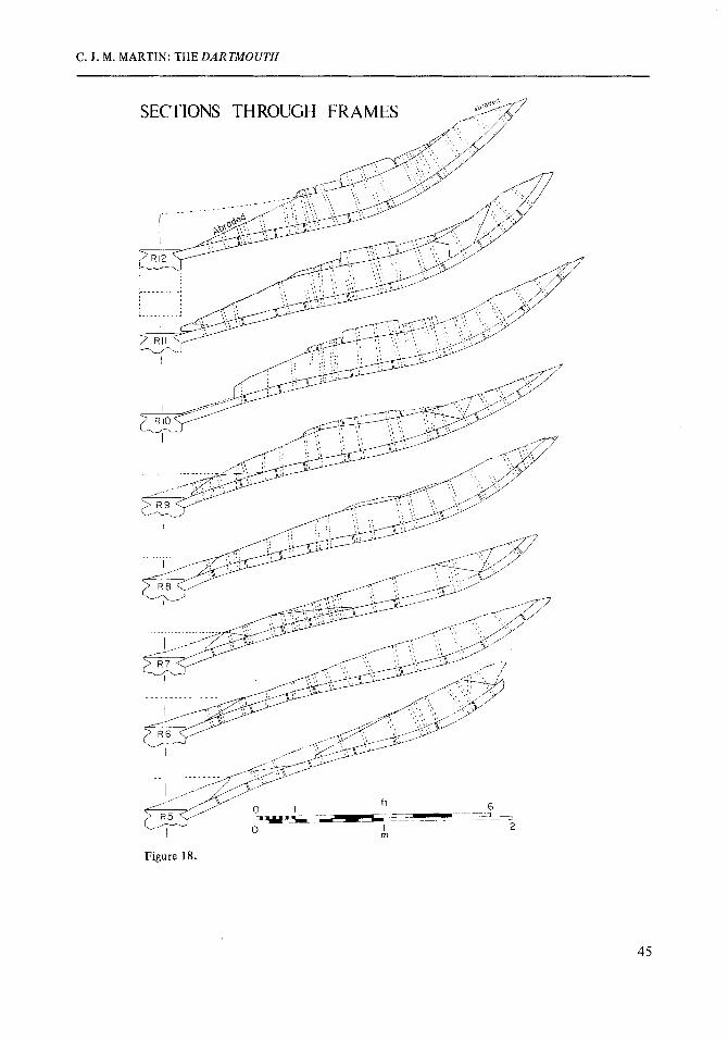
Figure 18.
45

NAUTICAL ARCHAEOLOGY, 7.1
proportions. Though it is much reduced by abrasion on the port side enough remains on the starboard for its maximum width, assuming symmetry, to be assessed as at least 4 ft (1.22 m). This is as large a piece of timber as could be derived from an average full-grown tree. The component, as restored, is trapezoidal in sec- tion, its bottom surface being the same width as the keel, to which it was bolted, while its sides flare out to match the rise of the garboard strakes, to which it was treenailed. Frames 1 to 4 butt against its upper edge, while frames 5 to 9 are clamped with tapering chocks into recesses cut in its under surface. This compo- nent ends just forward of frame 9, at a point which may be calculated to be 35 ft (10.67 m) forward of the stern end of the keel.
The way in which this timber is incorporated into the structure is unusual. Normally the frames ran continuously across the keel, clamped between it and the keelson, until well aft (cf. Fig. 19). As the frames ran aft they became increasingly hook-shaped to accommo- date the narrowing lines towards the stern, and
~
were brought into the solid deadwood only when this angle became too acute for hook frames to be practical (Longridge, 1955: 12- 13). The Durtmouth arrangement is quite different: at a point only a few feet aft of the midships frame-the exact location of which is uncertain, though it probably lies between frames 15 and 18-the frames were not con- tinuous, but were clamped port and starboard by the component under discussion which acted, as it were, as a continuous longitudinal chocked scarf. It is not impossible that this arrangement extended the full length of the ship, since the forwardmost frame which survives to its junction with the keel-frame 1 1-is still not continuous, although ad- mittedly the port and starboard terminal chocks here come very close together. The possibility must therefore remain undecided.
The arrangement, though unconventional, is ingenious. By bolting this component to the keel, and then by treenailing the garboard strakes to it, an extremely solid longitudinal unit is formed. The aftermost third of the ship,
Figure 19. Keltridge’s midships section of a small warship, 1684, redrawn for clarity. Note the overlaps on the joints between paired frames, and the use of floor riders.
46

C. J . M. MARTIN: T H € DARTMOUTH
where the frame ends simply butted into the component, could have been strengthened laterally by the insertion of short chock-shaped riders, while further forward riders integral with the frames themselves would run flat across the top of it (Fig. 17). Abrasion has, unfortunately, removed all trace of such riders, although both floor and futtock riders are mentioned in refit accounts (see Appendix).
If this arrangement extended the full length of the ship a conventional keelson may not have been strictly necessary, since this single component could have functioned as keelson, scarf chock, and rising deadwood. On the evi- dence, however, it would be unwise to rule out the probability of a separate keelson, though no identifiable remains of one now survive.
Two possible reasons for this departure from normal shipbuilding practice may be suggested. The first is the obvious advantage of a system in which very few grown shapes-especially hook frames-were required, and this would be especially relevant in the mid and later 17th century, when the problem of timber supply was becoming critical (Albion, 1952). Dart- mouth’s fine hull, with its considerable dead rise, would otherwise have consumed a large quantity of scarce and valuable ‘grown’ pieces.
Another reason may have been the re-keeling of 1678. The shipwright’s survey of 29 October 1677 (see Appendix) states that keel, false keel, false post, gripe and lower strakes were ‘all very much worm eaten’ and needed to be re- placed, and while no mention is made of the condition of the lower frames it is possible that the rot had penetrated there too. Replacing the frames as well as the keel would have been tantamount to rebuilding the ship, and possibly the arrangement under discussion was a solu- tion whereby the worm affected central sections of the frames were cut out and replaced.
The term ‘rising deadwood’ is offered for this unusual component, since its primary function seems to have been to give strength and shape to the dead rise of the hull.
Frames (Figs 18 and 19) All the frames examined were of oak. A total of 34 have been identified in situ, with a gap for a missing one (frame 2). This continuous run of
35 frames along the hull, involving a structural length of 35 ft (10.67 m), is identified in numerical series from the aftermost one (Fig. 12). It is noteworthy that the frames appear to be intentionally spaced at 1 ft (0.305 m) inter- vals: though timber sizes sometimes occasion slight deviation in individual cases, succeeding frames invariably correct this trend, which sug gests that centre lines were marked out by care- ful measurement before the frames were placed. The lack of identifiable carpenters’ marks sug gests that these had been chalked, as is common practice today. The frames are very closely spaced, and measure on average 10 in (0.25 m) wide by 8 in (0.20 m) deep.
Although the frames are here considered for convenience as single ‘ribs’, they should more properly be regarded as complementary pairs with joints set alternatively for strength (Fig. 19). The frame joints are chocked in the manner commonly believed to have been intro- duced by the Admiralty in 1714 (Longridge, 1955: 19; followed by McKee, 1976: 8); this find shows the system in use considerably earlier. The paired ribs are not, however, joined laterally, and depend for mutual in- tegrity on connection via the strakes and ceil- ing. They could not, therefore, have been pre- erected, and the hull must have been built by setting up and planking the keel and floors, adding futtocks, chocks, and further planking as appropriate. This method of construction is well illustrated in a Swedish treatise of 1691 (as published by Greenhill, 1976: 71) where, in fig. 2 of the reproduced illustration, a single midships control frame has been set up with ribbands to fair the intended hull shape. The frames and planks were then built up from the keel in exactly the manner suggested above.
Strakes (Figs 20 to 22) The ship’s outer planking, at least below the waterline, was exclusively of elm, and varied in thickness from 2.5 in (0.063 m) to 3 in (0.076 m), which accords well enough with the 3 in plank described in the shipwrights’ documents. The strakes were pinned to the framing, usually through to the ceiling, with spokeshaved oak treenails 1.5 in (0.038 m) in diameter, the heads of which had been tightened by a triangu- lar or criss-cross saw cut half an inch (0-013 m) deep into which oakum had been rammed
47

NAUTICAL ARCHAEOLOGY, 7.1
- 1 . . . . . . . S l l ~ - --I OUTSIDE STRAKE PLAN . . .
RI - R13
Treenail 3 Ball
Centre line of top of heel --- p ~
0 1
0 I 3
11 10 -
m
(Fig. 21). Some collar headed 1 in (0.025 m) iron bolts were also in evidence.
A detailed outside strake and fastenings plan of the recovered section of the hull is presented in Fig. 20. In general the aim seems to have been to place an inboard and outboard treenail at each plank/frame joint, although the positioning is often erratic. The lack of symmetry may well be deliberate, to avoid setting up lines of weakness along the grain of the planks. Sometimes only one treenail is used; rarely, as at S2/R1 and S4/R4, none at all. In addition to the more or less regular pattern a good many 'extra' tree- nails are to be seen, and these are best explained as dockyard additions intended to tighten up an ageing hull. The additions are sometimes clustered in groups, as at S la /Rl and S5/R12, but much more often they are placed singly to touch or even cut into an existing treenail, presumably to tighten it.
Another remarkable feature is t o be seen on the thin strake S4, where the treenails are placed so close to the edges that some cut
through the join between it and its neighbour- ing strakes. It may be significant that the 1678 refit included the replacement of three strakes on each side, presumably those nearest the keel. If we discount S2, which is a stealer, the thin and oddly treenailed S4 would be the strake bridging the gap between the old and new plank- ing, which perhaps accounts for its peculiarity.
0 3 i n
h 0 8 c m
Figure 21. Treenail heads, showing caulking cuts.
48
C. J. M. MARTIN: THE DARTMOUTH
The treenailing on S1 to S4, moreover, is less obviously regular than the patterns on the remaining strakes: this may be due to a deliber- ate avoidance of the original fastening holes in the frames and rising deadwood, for greater strength and tightness.
S2 and S6a are stealers-extra planks inserted to accommodate the widening surface area as the hull flares aft (Longridge, 1955: 52).
A small rectangu1a.r insert has been let into S1 and nailed through to the frame, apparently to stop a crack in the plank. This it has success- fully done, though a second crack has developed fore and aft from the inboard edge of the stop. The latter crack may well have happened during the break-up of the ship, and does not necess- arily reflect on the efficacy of the repair.
A number of sheet lead tingles (Fig. 22) were found among the wreckage, although none were observed fixed to the hull. Mainwaring (c. 1623: 177)recommends their use in stopping leaks inboard and out.
Figure 22. Sheet lead tingles.
An elm timber, marked ' W in Fig. 12, l o i n (0.25 m) wide, 6 in (0.15 m) thick and 22 ft (6.71 m) long lay partially pinned beneath the main structural complex but was unconnected to any surviving component, Its treenailing followed the general spacing and pattern observed on the 3 i n (0.076m) strakes, so its double thickness suggests that it comes from the side waling, above the waterline. This con- clusion is strengthened by the presence of a central hole 4 in (0.10 m) in diameter (hidden in the drawing) doubtless intended for a scup- per. At its shoreward end a shallow recess 25 in (0.63 m) wide had been cut into a side of the wale: this may well have been to accommodate one of the aft gunports where it cut through the line of the wale (cf. the second gunport
from the stern in Fig. 1). Mainwaring (c. 1623: 200) allows 30 in (0.76 m) for a demi-culverin port.
A fragment of bark was noted on the wale's edge, close to the postulated gunport, suggest- ing that this timber had been fitted not long before the ship was wrecked.
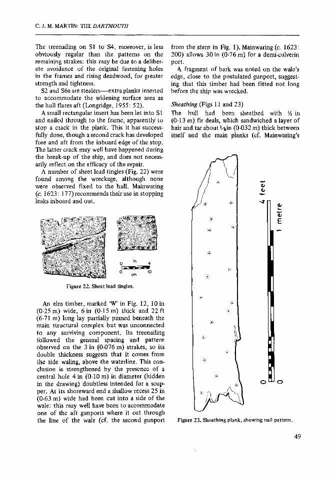
Sheathing (Figs 11 and 23) The hull had been sheathed with 54 in (0.13 m) fir deals, which sandwiched a layer of hair and tar about +*in (0.032 m) thick between itself and the main planks (cf. Mainwaring's
Figure 23. Sheathing plank, showing nail pattern.
49
NAUTICAL ARCHAEOLOGY, 7.1
‘thin boards, hair, and tar’ (c. 1623: 222). Some of these boards and hair felting survived in situ, showing that they had been placed so as to overlap the main plank joints, thus enhanc- ing the caulking of the ship (Fig. 11). The boards were held in place by flat headed iron nails, arranged in a zig-zag pattern of which Fig. 23 is a typical example.
Slight traces of hair adhering to the sides of the keel show that it had a similar sheathing: negative evidence, in the lack of suitable lead sheeting in any quantity, suggests that it had not been leaded.
Despite her sheathing, Dartmouth was much afflicted by shipworm, as evident both in docu- mentary sources and in the teredo drillings in her surviving timbers. That this infestation con- tinued for some time after wrecking is shown by drillings which work outwards from the interior of the ship (Fig. 10).
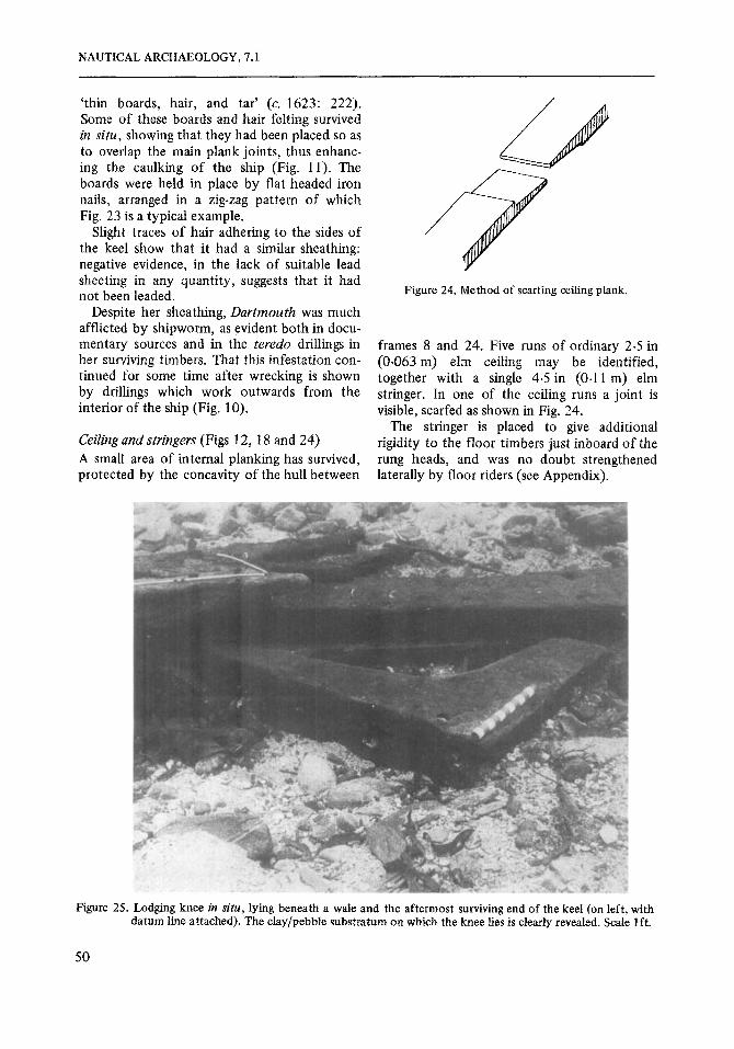
Ceiling and stringers (Figs 12, 1 8 and 24) A small area of internal planking has survived, protected by the concavity of the hull between
Figure 24. Method of scarfing ceiling plank.
frames 8 and 24. Five runs of ordinary 2.5 in (0.063 m) elm ceiling may be identified, together with a single 4.5 in (0.1 1 m) elm stringer. In one of the ceiling runs a joint is visible, scarfed as shown in Fig. 24.
The stringer is placed to give additional rigidity to the floor timbers just inboard of the rung heads, and was no doubt strengthened laterally by floor riders (see Appendix).
Figure 25. Lodging knee in situ, lying beneath a wale and the aftermost surviving end of the keel (on left, with datum line attached). The clay/pebble substratum on which the knee lies is clearly revealed. Scale lft.
50

C. J. M. MARTIN: THE DARTMOUTH
Figure 26. The lodging knee, showing slots for ledges. Scale in half metres. Photo by courtesy of the National Museum ofhtiquitiesof Scotland.
Lodging knee (Figs 25,26 and 27) The only identifiable component from the internal upper parts of the ship was a well pre- served lodging knee, which lay pinned beneath the after end of the coherent structure (Fig. 25). The knee, which is of oak, is a 'grown' timber, having been selected from a junction point between the trunk and a branch so that the grain followed its shape. The function of lodging knees was to act as horizontal braces between the sides of the ship and the maindeck beams (see Fig. 30), and consequently it may be used as evidence for the general arrangement and spacing of these members.
The knee is set at an obtuse angle of 94", sug- gesting that it was placed either fore or aft of midships, where it would have been set at right angles. Since it was found at the aft end of the site, it is probably from the collapsed aft upper- works, in which case, from the position of its
0 0
4 f t I +---- m I
ledge 'lots, it is a starboard knee* On the analogy Figure 27. Phn and outside elevations of the lodging of the Keltridge fifth rate draught an angle of 4" beyond the right angle would be reached at a
knee, with a reconstruction demonstrating its function in the hull.
51

NAUTICAL ARCHAEOLOGY, 7.1
point about halfway aft from midships, which accords well with the actual position of the knee in relation to the coherent structure as interpreted above. It thus almost certainly represents, along with the wale and the col- lapsed frames in the keel trench, the remains of the disintegrated starboard side.
Figure 27 includes a reconstructed section of the gundeck structure as projected from the knee.
Scupper liners (Fig. 28) The lead scupper liners, which allowed drain- age through the hull from the waterways, pro- vide evidence €or the thickness of the upper structure. The liners, which were set at a down- wards angle of about 25' to ensure a free flow, are characterized at their inboard ends by an L-shaped apron which was edge-nailed to the waterway and side members, and at their out- board ends by a flange whch was nailed to the
outer planking. The scuppers were solder jointed along the upper side of the pipe, and sealed with a %in (0.013 rn) strip of pitch. Flapper valves of leather attached to the top of the outer flange would have prevented the scuppers from taking in water should they roll below water or be struck by waves.
The longest liner (no. 1) has a horizontal length of 15 in (0.38 m), which suggests that it probably passed through inner planking, a frame, and a wale. If, like the one identified, this wale was 6 in (0.15 m) thick, and the inner planking was, say, 2 in (0-05 m), then the frame will have been 7 in (0.18 m) thick-only slightly less than the 8 in (0.20 m) depth recorded €or the floor timbers. No. 2, with a 12 in horizontal length, would also fit a 7 in (0.18 rn) frame thickness if we assume standard 3 in (0-08 m) outer planking and 2 in (0.05 m) inner. It is probable therefore that at main deck level the frames were only marginally slighter than at the floors, if at all.
0 12 in
0 30 cm '$
Figure 28. Lead scupper-liners (1-3) and lead pissdale pipe (4).
52

C. J. M. MARTIN: THE DARTMOUTH
Much slighter framing, however, is implied by no. 3, which measures only 8 in (0-20 m) hori- zontally. We may surmise that this comes from the hull superstructure, where the timbering was naturally lighter. According to the 1678 refit the forecastle planking was 2 in (0.05 m) thick: if this scupper comes from there, and if we presume an inner lining of the same thick- ness, then the framing here will have been re- duced to a depth of 4 in (0-10 m)-only half its dimension on the floors.
The leaden ‘pissdale pipe’ (no. 4) was prob- ably set vertically, otherwise its seam would have been on the underside in a manner avoided with the horizontal scuppers: upright, its slight angling ensures that the seam lies away from the natural waste run. Set in a block between the head beams and carlings beyond the bows (cf. the arrangements on Victoly (Longridge, 1955: 82)) this pipe would have provided a service- able if somewhat Spartan convenience for the crew.
Discussion The Dartmouth’s structural remains have shown interesting divergences from commonly accepted interpretations of 17th century naval architectural techniques. Whether for some reason this particular ship was atypical, or whether there was a greater degree of techni- cal variance in shipbuilding practice within this period than has hitherto been supposed, can only be decided by the investigation of parallel sites. But in either case the value of ship archaeology in elucidating such matters, even in otherwise well documented periods, cannot be denied.
The most significant feature of construc- tion is undoubtedly the unusual use of rising deadwood to lock keel, garboards and frames together. We know that this arrangement extended at least as far forward as a few feet aft of midships: the key question of whether it extended beyond that, perhaps for the full length of the ship, cannot be answered on the available evidence. Nor can we be certain, as discussed above, that this peculiar arrange- ment was not a rtlodification occasioned by the fitting of a new keel in 1678. But the irregular treenailing of the first three strakes, which were also replaced in 1678, tends to suggest that the internal components to whch they were pinned were original, since otherwise there would have been no need to avoid the old holes. Further- more, had an operation so costly in effort and materials as the modification of the ship in this way taken place along with the re-keeling, men- tion of it would surely have found its way into the refit accounts. On balance, then, the rising deadwood was probably original, and an inte- gral part of the design.
Such a system would not only eliminate the need for hook frames, but would also impart a special solidity to the V-shaped dead rise which would otherwise have been a weak point in this light and sleek class of vessel. Something of the ship’s underwater lines may be gauged from the curves of the frame sections (Fig. 18), although it must be admitted that the paper reconstructions of these curves, whether due to the distortion of the frames themselves or to recording errors, are not good enough to permit accurate lines to be projected. It is hoped that further work, including the construction of a
20 O- 0 6
rn Figure 29. Gundeck structure and half-breadth plan of a large fifth-rate, 1684 (redrawn from Keltridge).
53
NAUTICAL ARCHAEOLOGY, 7.1
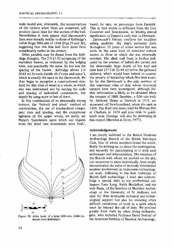
scale model and, ultimately, the reconstruction of the timbers when these are conserved, will produce faired lines for this section of the hull. Nevertheless it does appear that Dartmouth’s lines were broadly similar to those of Keltridge’s rather larger fifth rate of 1648 (Figs 29 and 30), suggesting that this fine hull form dates from considerably earlier in the century.
Other parallels may be drawn from the Kelt- ridge draughts. The 5 ft (1 -52 m) spacing of the maindeck beams, as indicated by the lodging knee, was practically the same. So too was the spacing of the frames-Keltridge allows 2 ft (0.61 m) for each double rib (‘room and space’), which is exactly the same as the Dartmouth. We thus begin to recognize a constructional stan- dard for this class of vessel as a whole, in which size was determined not by varying the scale and spacing of individual components, but simply by using more or less of them.
In this combination of an abnormally strong bottom, the ‘futtock and plank‘ method of construction, the use of standardized compo- nent sizes and spacing, and the exceptional lightness of the upper works, we surely see Pepys’s ‘foundation upon which our frigates from the third rate downwards were built’,
u I f t 0 do
O m 3
Figure 30. After body of a large fifth-rate, 1684 (re- drawn from Keltridge).
based, he says, on prototypes from Dunkirk. This in turn points to influence from the Low Countries and Scandinavia, so lending special significance to Tippets’s early visit to Denmark.
Dartmouth’s history confirms her excellent sailing qualities: the ship’s particular forte throughout 35 years of active service life was work in the same kind of restricted inshore waters as those in which she was eventually wrecked. Her sleek hull form is further indi- cated by the amount of ballast she carried and the abnormally large depth of her keel and false keel (17.5 in (0.44 m) below the garboard rabbets), which would have helped to counter the penalty of instability which fine lines exact. So far the Dartmouth is the only survivor of this important class of ship whose structural remains have been investigated, although fur- ther information is likely to be obtained when the remains of HMS Sapphire, a fifth rate built by Anthony Deane at Harwich in 1675, are excavated off Newfoundland, where she sank in 1696. The third rateAnne, built by Phineas Pett at Chatham in 1678 and now sunk in quick- sands near Hastings, will also be interesting in this respect (Marsden & Lyon, 1977).
Acknowledgements I am deeply indebted to the Bristol Undersea Archaeology Branch of the British Sub-Aqua Club, four of whose members found the wreck, firstly for inviting me to direct the investigation, and secondly for participating in it with such enthusiasm and determination. The members of the Branch with whom we worked on the site, too numerous to name individually, have amply demonstrated the value of seriously intentioned amateur involvement in underwater archaeologi- cal work, following in the best traditions of British field archaeology. I must also acknow- ledge a special debt to my professional col- leagues Tony Long, Keith Muckelroy, and my wife Paula, of the Institute of Maritime Archae- ology at the University of S t Andrews, not only for their invaluable technical and archae- ological support but also for enduring often difficult conditions of work in a spirit which went far beyond the call of duty. We profited greatly from visits by other diving archaeolo- gists, who included Professor David Switzer of the American Institute of Nautical Archaeology,
54

C. J. M. MARTIN: THE DARTMOUTH
Jeremy Green of the Western Australian Museum, Lous Zuiderbaan, Thijs Maarleveld, Richard Larn, Jill Sweetnam and Celie O’Rahilly. I would like to thank all of them for their help and stimulating company.
Throughout the project our tasks were eased by the unfailing courtesy, friendliness and co- operation of everyone we met on Mull. Our debt to Richard and Yvonne Greeves, of the Mull Diving Centre, Salen, can never be repaid: without the facilities and kindness they gave so freely (in every sense of the word) the Institute team would, quite simply, have been unable to function. I would also like to thank the owners of the Ardtornish Estate for their kind permis- sion to use Eilean Rubha an Ridire as a base for our operations, and particularly the Factor, Iain Thornber, for his personal interest and support.
The Institute’s travel and operating costs were met by generous contributions from the British Sub-Aqua Club, British Petroleum, Chevron Petroleum (UK) and the Society for Nautical Research. I would like to express my deep gratitude to these sponsors for making our involvement possible.
Much of the project’s success has been due to the participation, from an early stage, of the National Museum of Antiquities of Scotland, which has now acquired the wreck collection in its entirety. My sincere thanks go to the Board of Trustees and, in particular, to the Keeper, Robert Stevenson, for generous and enlightened support throughout. The laborious work of transporting and conserving the heavy and
fragile timbers has been undertaken with great skill by the Museum’s Research Laboratory, and I am deeply indebted to Dr Hugh McKerrell, Jack Howells, and other members of the Laboratory staff for co-operating, at consider- able inconvenience to themselves, in the dis- mantling and recording of the structural remains before conservation processes rendered these temporarily unavailable. In the task of record- ing I must also acknowledge with thanks the valuable assistance of Jane Weeks.
John Adnams, of the Bristol Undersea Archae- ology Branch, has been unstinting in making his copious historical researches available to me, and allowing me to make full use of them in this paper. All the documentary evidence I have cited is derived from his work.
In interpreting the remains I have gained much from discussions with members of the Society for Nautical Research and with staff members of the National Maritime Museum, Greenwich. I am especially grateful to David Lyon, of the Museum, both for his helpful advice and for providing me with full-scale copies of the Keltridge draughts.
Finally I would like to express my thanks to the Runciman Committee and the Department of Trade, whose scheduling of the wreck site under the Protection of Wrecks Act ensured that the work was able to go forward without interference, and to the vast majority of the diving community at large for respecting both the letter and spirit of the Act.
Appendix
Edited prdcis of surveys and refits (PRO ADM 10613 11 8-9 ERD/ 1363) Note: technical terns, which are transcribed direct, are indicated in italics.
Refit at Captain Castle’s Dock, Rotherhithe, 6 June 1678
Fitting a new maine keele 88 ft 6 in x 13 in square. . . . . . . . . . . . . . . . . . . . . Fitting a false keele 88 ft 6 in x 13 in X 8 in.
and a fake post 18 ft x 10 in. . . . . . . . . . . . . . . . . . . . . . . . . . . . . . . . . .
with a further 265 f t on the boughs and buttock.
gudgeons, and a new tiller). . . . . . . . . . . . . . . . . . . . . . . . . . . . . . . . . . . .
. . . . . . . . . . . . . . . . . . . . . . . . Fitting a maine post 18 ft X 20 in
Shifting and replacing 3 in strakes (3 on each side underwater), totalling 7 10 ft, . . . . . . . . . . . . . . . . . . . .
Shifting 39 ft of 4 in plank on the boughs. . . . . . . . . . . . . . . . . . . . . . . . . . . Removing the rother, replacing rother irons (1 new brace and pintle, 2 new
E s d 1 3 2 . 1 5 . 0
8 . 1 6 . 0
2 2 . 0 0 . 0
2 1 . 1 7 . 6 6 . 1 0 . 0
9 . 0 0 . 0
55
NAUTICAL ARCHAEOLOGY, 7.1
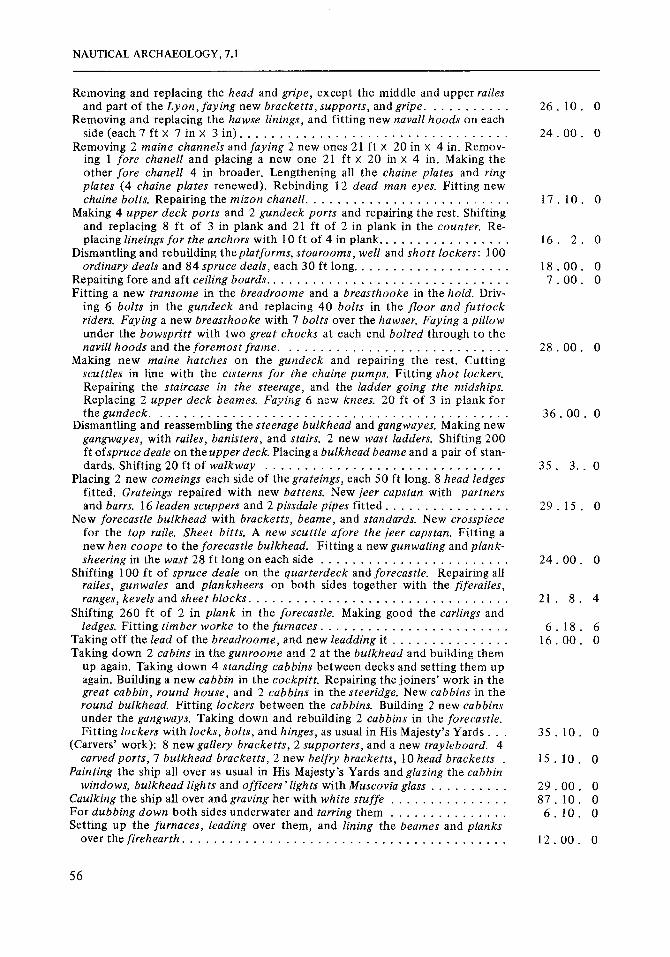
Removing and replacing the head and gripe, except the middle and upper railes
Removing and replacing the hawse linings, and fitting new naval1 hoods on each
Removing 2 maine channels and faying 2 new ones 21 ft X 20 in x 4 in. Remov- ing 1 fore chanell and placing a new one 21 ft X 20 in X 4 in. Making the other fore chanell 4 in broader. Lengthening all the chaine plates and ring plates (4 chaine plates renewed). Rebinding 12 dead man eyes, Fitting new
Making 4 upper deck ports and 2 gundeck ports and repairing the rest. Shifting and replacing 8 f t of 3 in plank and 21 f t of 2 in plank in the counter. Re-
Dismantling and rebuilding the platforms, stoarooms, well and shott lockers: 100
Repairing fore and aft ceiling boards. . . . . . . . . . . . . . . . . . . . . . . . . . . . . . . Fitting a new transome in the breadroome and a breasthooke in the hold. Driv-
ing 6 bolts in the gundeck and replacing 40 bolts in the floor and fut tock riders. Faying a new breasthooke with 7 bolts over the hawser. Faying a pillow under the bowspritt with two great chocks at each end bolted through t o the navill hoods and the foremost frame. . . . . . . . . . . . . . . . . . . . . . . . . . . . .
Making new maine hatches on the gundeck and repairing the rest. Cutting scuttles in line with the cisterns for the chaine pumps. Fitting shot lockers. Repairing the staircase in the steerage, and the ladder going the midships. Replacing 2 upper deck beames. Faying 6 new knees. 20 ft of 3 in plank for thegundeck. . . . . . . . . . . . . . . . . . . . . . . . . . . . . . . . . . . . . . . . . . . . .
Dismantling and reassembling the steerage bulkhead and gangwayes. Making new gangwayes, with railes, banisters, and stairs. 2 new wast ladders. Shifting 200 ft ofspruce deale on the upper deck. Placing a bulkhead beame and a pair of stan-
Placing 2 new comeings each side of the grateings, each 50 ft long. 8 head ledges fitted. Grateings repaired with new battens. New jeer capstan with partners
New forecastle bulkhead with bracketts, beame, and standards. New crosspiece for the top raile. Sheet bitts. A new scuttle afore the jeer capstan, Fitting a new hen coope to the forecastle bulkhead. Fitting a new gunwaling and plank-
Shifting 100 f t of spruce deale on the quarterdeck and forecastle. Repairing all railes, gunwales and planksheers on both sides together with the fiferailes,
Shifting 260 ft of 2 in plank in the forecastle. Making good the carlings and
Taking off the lead of the breadroome, and new leadding it . . . . . . . . . . . . . . . Taking down 2 cabins in the gunroome and 2 a t the bulkhead and building them
up again. Taking down 4 standing cabbins between decks and setting them up again. Building a new cabbin in the cockpitt. Repairing the joiners’ work in the great cabbin, round house, and 2 cabbins in the steeridge. New cabbins in the round bulkhead. Fitting lockers between the cabbins. Building 2 new cabbins under the gangways. Taking down and rebuilding 2 cabbins in the forecastle.
(Carvers’ work): 8 new gallery bracketts, 2 supporters, and a new trayleboard. 4 carved ports, 7 bulkhead bracketts, 2 new belfry bracketts, 10 head bracketts .
Painting the ship all over as usual in His Majesty’s Yards and glazing the cabbin windows, bulkhead lights and officers’lights with Muscovia glass . . . . . . . . . .
Caulking the ship all over and graving her with white stuffe . . . . . . . . . . . . . . . For dubbing down both sides underwater and tarring them . . . . . . . . . . . . . . . Setting up the furnaces, leading over them, and lining the beames and planks
over the firehearth. . . . . . . . . . . . . . . . . . . . . . . . . . . . . . . . . . . . . . . . .
and part of the Lyon, faying new bracketts, supports, and gripe.
side (each 7 ft x 7 in x 3 in). . . . . . . . . . . . . . . . . . . . . . . . . . . . . . . . . .
. . . . . . . . . .
chaine bolts. Repairing the mizon chanell. . . . . . . . . . . . . . . . . . . . . . . . . .
placing lineings for the anchors with 10 ft of 4 in plank. . . . . . . . . . . . . . . . .
ordinary deals and 8 4 spruce deals, each 30 ft long. . . . . . . . . . . . . . . . . . . .
dards. Shifting 20 ft of walkway
and barrs. 16 leaden scuppers and 2 pissdale pipes fitted. . . . . . . . . . . . . . . .
. . . . . . . . . . . . . . . . . . . . . . . . . . . . . .
sheering in the wast 28 ft long on each side
ranges, kevels and sheet blocks. . . . . . . . . . . . . . . . . . . . . . . . . . . . . . . . .
ledges. Fitting timber worke to the furnaces. . . . . . . . . . . . . . . . . . . . . . . .
. . . . . . . . . . . . . . . . . . . . . . . .
Fitting lockers with locks, bolts, and hinges, as usual in His Majesty’s Yards . . .
2 6 . 1 0 . 0
2 4 . 00. 0
1 7 . 1 0 . 0
1 6 . 2 . 0
1 8 . 0 0 . 0 7 . 0 0 . 0
2 8 . 0 0 . 0
3 6 . 0 0 . 0
3 5 . 3 . . 0
2 9 . 1 5 . 0
2 4 . 0 0 . 0
2 1 . 8 . 4
6 . 1 8 . 6 1 6 . 0 0 . 0
3 5 . 1 0 . 0
1 5 . 10. 0
2 9 . 0 0 . 0 8 7 . 1 0 . 0
6 . 1 0 . 0
1 2 . 0 0 . 0
56
C. J. M. MARTIN: THE DARTMOUTH
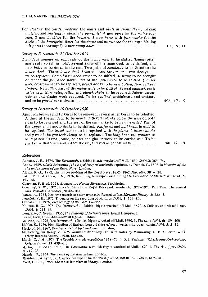
For cleating the yards, wedging the masts and shutt in about them, making scuttles, and shutting in about the bowspritt. 4 new barrs for the maine cap- stan, 3 new bucklers for the hawsers. 3 new barrs with iron worke for the heele of the bowspritt. Burrs for the doors and ironworke for the tops. Making 6 f t ports (doorways?). 2 new pump dales . . . . . . . . . . . . . . . . . . . . . . . . . 1 9 . 1 9 . 11
Survey a t Portsmouth, 27 October 1679 2 gundeck beames on each side of the maine mast to be shifted ‘being rotten
and ready to fall in hold’. Several knees of the same deck to be shifted, and new bolts to be drove in the rest. Two pairs of standards to be fitted to the lower deck. Three lower deck beames-one broken and two decayed- to be replaced. Some lower deck knees to be shifted, A string to be brought on under the gun deck ports. Part of the upper deck to be shifted. Quarter deck crossbeames to be replaced. Breast hooks to be new bolted. New cathead timbers. New tillar. Part of the maine wale to be shifted. Several gundeck ports to be new. Gun wales, railes, and planck sheirs to be repaired. Joiner, carver, painter and glazier work required. To be caulked withinboard and without, and to begraved per estimate . . . . . . . . . . . . . . . . . . . . . . . . . . . . . . . . , 408 . 17 . 9
Survey a t Portsmouth, 10 October 1680 3gundeck beames and 12 knees to be renewed. Several other knees to be rebolted.
A third of the gundeck to be new laid. Several planks below the wale on both sides to be renewed and the rest of the old worke to be new trenailed. Part of the upper and quarter decks to be shifted. Platforms and bulkheads in hold to be repaired. The bread roome to be repaired with tin plates. 2 breast hooks and part of the gundeck clamp to be replaced. The long boat and pinnace to be repaired. Carver, joiner, painter and glazier work to be carried out. To be caulked withinboard and withoutboard, and graved per estimate . . . . . . . . . . 740 . 12 . 9
References Adnams, J. R., 1974, The Dartmouth, a British frigate wrecked off Mull, 1690. IJNA,3: 269-74. Anon., 1689, Gloria Britannica (The Royal Navy of England): reprinted by Derrick, C., 1806, inMemoirs of the
Albion, R. G., 1952, The timber problem of the Royal Navy, 1652-1862. Mar. Mirr. 38: 4-20. Baker, P. E. & Green, J. N., 1976, Recording techniques used during the excavation of the Batavia, IJNA, 5:
Chapman, F. H. af, 1768, Architectura Navalis Mercatoria. Stockholm. Courtney, T. W., 1975, Excavations at the Royal Dockyard, Woolwich, 1972-1973. Part Two: The central
Eames, A., 1973, Maritime records at Caernarvonshire Record Office. Maritime History, 2: 222-3. Fenwick, V. H., 1972, Thoughts on the recording of old ships. IJNA, 1: 177-80. Greenhill, B., 1976, Archaeology of the boat. London. Holman, R. G., 1975, The Dartmouth, a British frigate wrecked off Mull, 1690. 2. Culinary and related items.
Longridge, C. Nepean, 1955, m e anatomy of Nelson’s ships. Hemel Hempstead. Lorne, Lord, 1898, Adventures in legend. London. McBride, P., 1976, The Dartmouth, a British frigate wrecked off Mull, 1690. 3. The guns. IJNA, 5 : 189-200. McKee, E., 1976, Identification of timbers from old ships of north-western European origin. IJNA, 5: 3-12. MacLeod, N., 1867, Reminiscences of Highland parish. London. Mainwaring, Sir Henry, c. 1625, Seaman’s dictionary. Ed. with notes by Mainwaring, G. E. & Perrin, W. G.
Martin, C. J. M., 1973, The Spanish Armada expedition 1968-70. In D. J . Blackman (Ed.),Marine Archaeotogy,
Martin, P. F. de C., 1977, The Dartmouth, a British frigate wrecked of Mull, 1690. 4. The clay pipes. IJNA,
Marsden, P., 1974, The wreck of the Amsterdam. London. Marsden, P. & Lyon, D., A wreck believed to be the warship Anne, lost in 1690. IJNA, 6: 9-20. Naish, G. P. B., 1968, The Wasz her place in history. London.
rise and progress of the Royal Navy. London.
143-58.
area. Post-Med. Archaeol., 9: 42-102.
IJNA, 4: 253-65.
(Navy Records Society), 1920. London.
Colston Papers, 23: 439-61.
6: 219-23.
57
NAUTICAL ARCHAEOLOGY, 7.1
Pepys, S . (no date), Naval Minutes. Ed. with notes by Tanner, J. R. (Navy Records Society), 1926. London. Robinson, M. S., 1958, The Van de Vede drawings. A catalogue of drawings in the National Maritime Museum
Wood, E. S., 1963, Field guide to archaeology. London. Cambridge.
Notes [ 11 As Pepys implies, 'frigate' was a non-specific term applied to small warships throughout the second half of
the 17th century, and the Dartmouth herself is frequently so described in contemporary documents. How- ever, in view of the highly specialized nature of the frigate as a class from the mid-18th century onwards, it is more appropriate when speaking of 17th century warships to describe them solely in terms of 'rate'.
[2] I have adopted the Imperial standard of measurement in this study because it is to this standard that the Dartmouth was built and to which all the documentary evidence conforms. That the modern British stan- dard is identical to its 17th century predecessor is well known, and gains confirmation in the present case by the discovery on the wreck site of an inch-graduated brass rule. Metric equivalents, where appropriate, are given.
Note on technical terms As far as possible I have followed the usages indicated in Mainwaring's Seaman's dictionary (c 1623), augmented where necessary by A. Anstead's Dictionary of sea terms (Glasgow, 1920) and the Oxford English Dictionary.
Note on Iocation The wreck is located a t 56"30'.19 N: 5"41'.95 W. See Admiralty Chart 2390 (1976) and 1 : 10 000 Ordnance Survey Sheet NM 74 SW (1974).
58