Embed Size (px)
Citation preview
Dredging
Processes
Dr.ir. Sape A. Miedema
The Cutting of Sand, Clay & Rock Excavating Equipment
The Cutting of Sand, Clay & Rock – Excavating Equipment
Copyright © Dr.ir. S.A. Miedema Page 2 of 58
The Cutting of Sand, Clay & Rock – Excavating Equipment
Copyright © Dr.ir. S.A. Miedema Page 3 of 58
Dredging Processes The Cutting of Sand, Clay & Rock
Excavating Equipment
By
Dr.ir. Sape A. Miedema
The Cutting of Sand, Clay & Rock – Excavating Equipment
Copyright © Dr.ir. S.A. Miedema Page 4 of 58
Dredging Processes The Cutting of Sand, Clay & Rock
Excavating Equipment
The Cutting of Sand, Clay & Rock – Excavating Equipment
Copyright © Dr.ir. S.A. Miedema Page 5 of 58
Preface
Lecture notes for the course OE4626 Dredging Processes, for the MSc program Offshore & Dredging Engineering, at the Delft University of Technology.
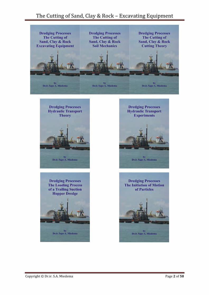
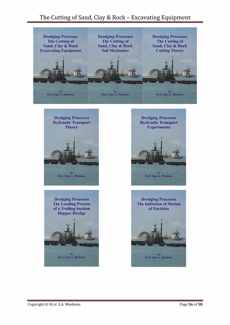
By Dr.ir. Sape A. Miedema, Sunday, January 13, 2013 In dredging, trenching, (deep sea) mining, drilling, tunnel boring and many other applications, sand, clay or rock has to be excavated. The productions (and thus the dimensions) of the excavating equipment range from mm3/sec - cm3/sec to m3/sec. In oil drilling layers with a thickness of a magnitude of 0.2 mm are cut, while in dredging this can be of a magnitude of 0.1 m with cutter suction dredges and meters for clamshells and backhoe’s. Some equipment is designed for dry soil, while others operate under water saturated conditions. Installed cutting powers may range up to 10 MW. For both the design, the operation and production estimation of the excavating equipment it is important to be able to predict the cutting forces and powers. After the soil has been excavated it is usually transported hydraulically as a slurry over a short (TSHD’s) or a long distance (CSD’s). Estimating the pressure losses and determining whether or not a bed will occur in the pipeline is of great importance. Fundamental processes of sedimentation, initiation of motion and ersosion of the soil particles determine the transport process and the flow regimes. In TSHD’s the soil has to settle during the loading process, where also sedimentation and erosion will be in equilibrium. In all cases we have to deal with soil and high density soil water mixtures and its fundamental behavior. This book gives an overview of the equipment involved in cutting processes. This book will give engineers an impression of the diversity of the excavating equipment and is the 1st of 7 books. Part 1: The Cutting of Sand, Clay & Rock – Excavating Equipment Part 2: The Cutting of Sand, Clay & Rock – Soil Mechanics Part 3: The Cutting of Sand, Clay & Rock - Theory Part 4: The Loading Process of a Trailing Suction Hopper Dredge. Part 5: The Initiation of Motion of Particles.. Part 6: Hydraulic Transport – Theory. Part 7: Hydraulic Transport – Experiments. Dr.ir. Sape A. Miedema
Dr.ir. Sape A. Miedema Delft University of Technology
Delft, the Netherlands Sunday, January 13, 2013

The Cutting of Sand, Clay & Rock – Excavating Equipment
Copyright © Dr.ir. S.A. Miedema Page 6 of 58
The Cutting of Sand, Clay & Rock – Excavating Equipment
Copyright © Dr.ir. S.A. Miedema Page 7 of 58
Table of Contents
Chapter 1: History 9
Chapter 2: Bucket Ladder Dredges 11
Chapter 3: Cutter Suction Dredges (CSD) 13
Chapter 4: Trailing Suction Hopper Dredges (TSHD) 19
Chapter 5: Backoe Dredges 25
Chapter 6: Clamshell Dredges 29
Chapter 7: Bucket Wheel Dredges 33
Chapter 8: Deep Sea Mining 37
Chapter 9: Trenching 41
Chapter 10: PDC Cutters 47
Chapter 11: Dry Mining/TBM 49
Chapter 12: List of Figures 53
Chapter 13: About the Author. 57

The Cutting of Sand, Clay & Rock – Excavating Equipment
Copyright © Dr.ir. S.A. Miedema Page 8 of 58
The Cutting of Sand, Clay & Rock – Excavating Equipment
Copyright © Dr.ir. S.A. Miedema Page 9 of 58
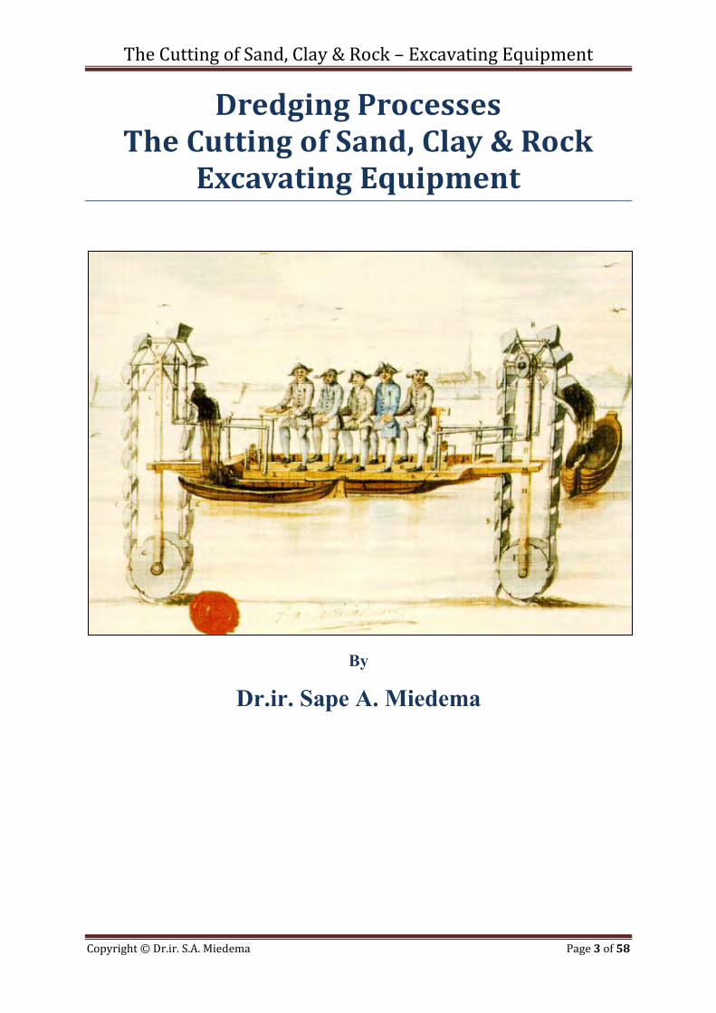
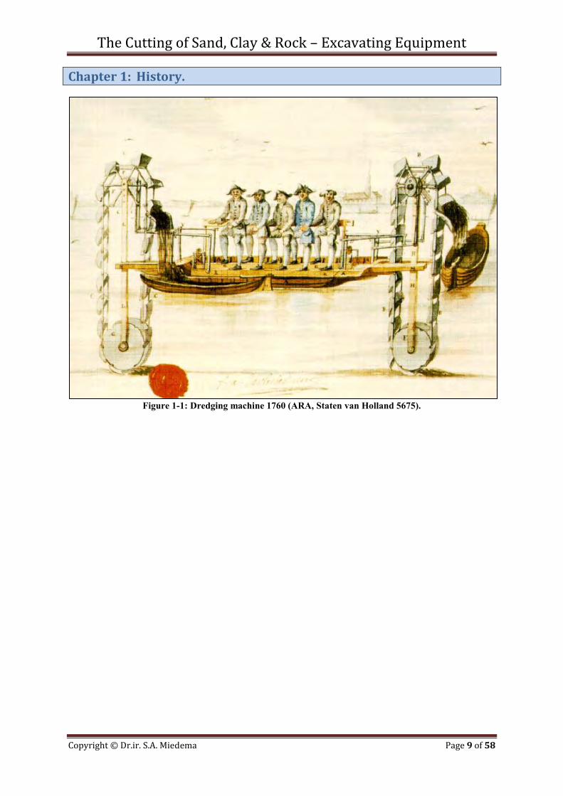
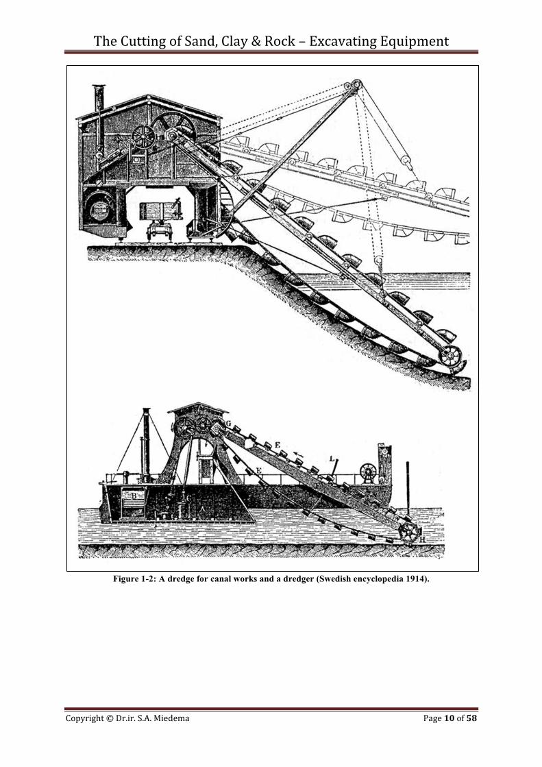
Chapter 1: History.
Figure 1-1: Dredging machine 1760 (ARA, Staten van Holland 5675).
The Cutting of Sand, Clay & Rock – Excavating Equipment
Copyright © Dr.ir. S.A. Miedema Page 10 of 58
Figure 1-2: A dredge for canal works and a dredger (Swedish encyclopedia 1914).
The Cutting of Sand, Clay & Rock – Excavating Equipment
Copyright © Dr.ir. S.A. Miedema Page 11 of 58
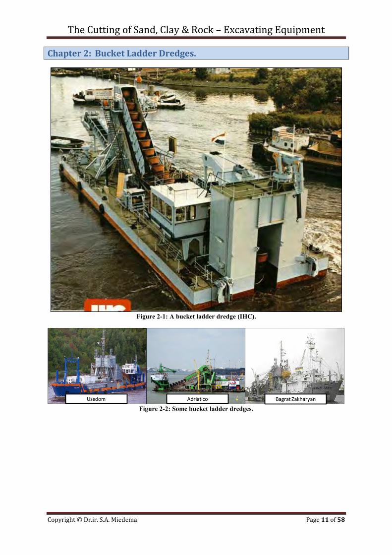
Chapter 2: Bucket Ladder Dredges.
Figure 2-1: A bucket ladder dredge (IHC).
Figure 2-2: Some bucket ladder dredges.
Usedom Bagrat ZakharyanAdriatico

The Cutting of Sand, Clay & Rock – Excavating Equipment
Copyright © Dr.ir. S.A. Miedema Page 12 of 58
The Cutting of Sand, Clay & Rock – Excavating Equipment
Copyright © Dr.ir. S.A. Miedema Page 13 of 58
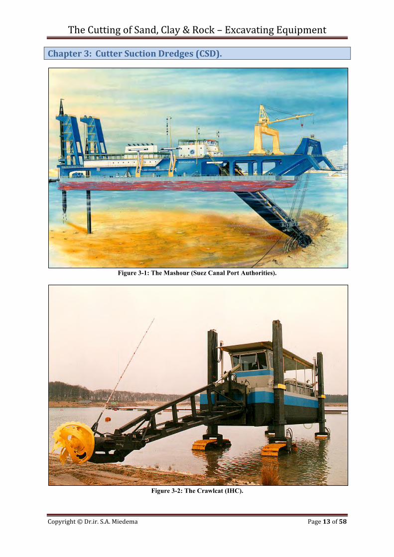
Chapter 3: Cutter Suction Dredges (CSD).
Figure 3-1: The Mashour (Suez Canal Port Authorities).
Figure 3-2: The Crawlcat (IHC).
The Cutting of Sand, Clay & Rock – Excavating Equipment
Copyright © Dr.ir. S.A. Miedema Page 14 of 58
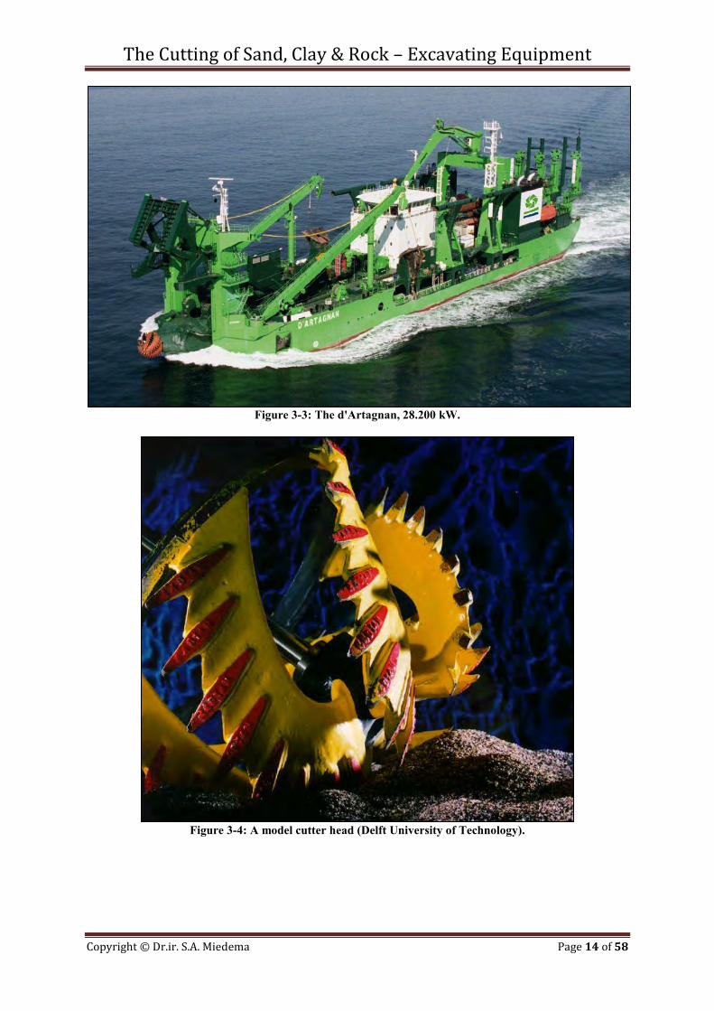
Figure 3-3: The d'Artagnan, 28.200 kW.
Figure 3-4: A model cutter head (Delft University of Technology).
The Cutting of Sand, Clay & Rock – Excavating Equipment
Copyright © Dr.ir. S.A. Miedema Page 15 of 58
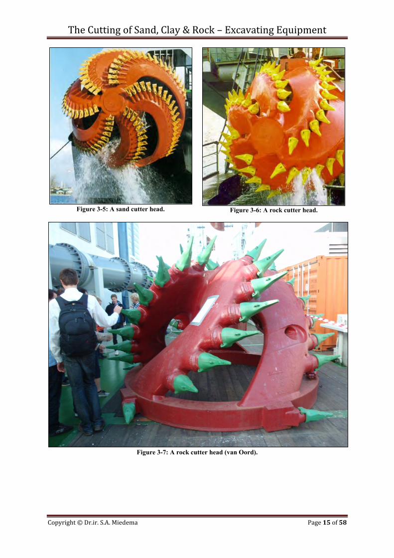
Figure 3-5: A sand cutter head.
Figure 3-6: A rock cutter head.
Figure 3-7: A rock cutter head (van Oord).
The Cutting of Sand, Clay & Rock – Excavating Equipment
Copyright © Dr.ir. S.A. Miedema Page 16 of 58
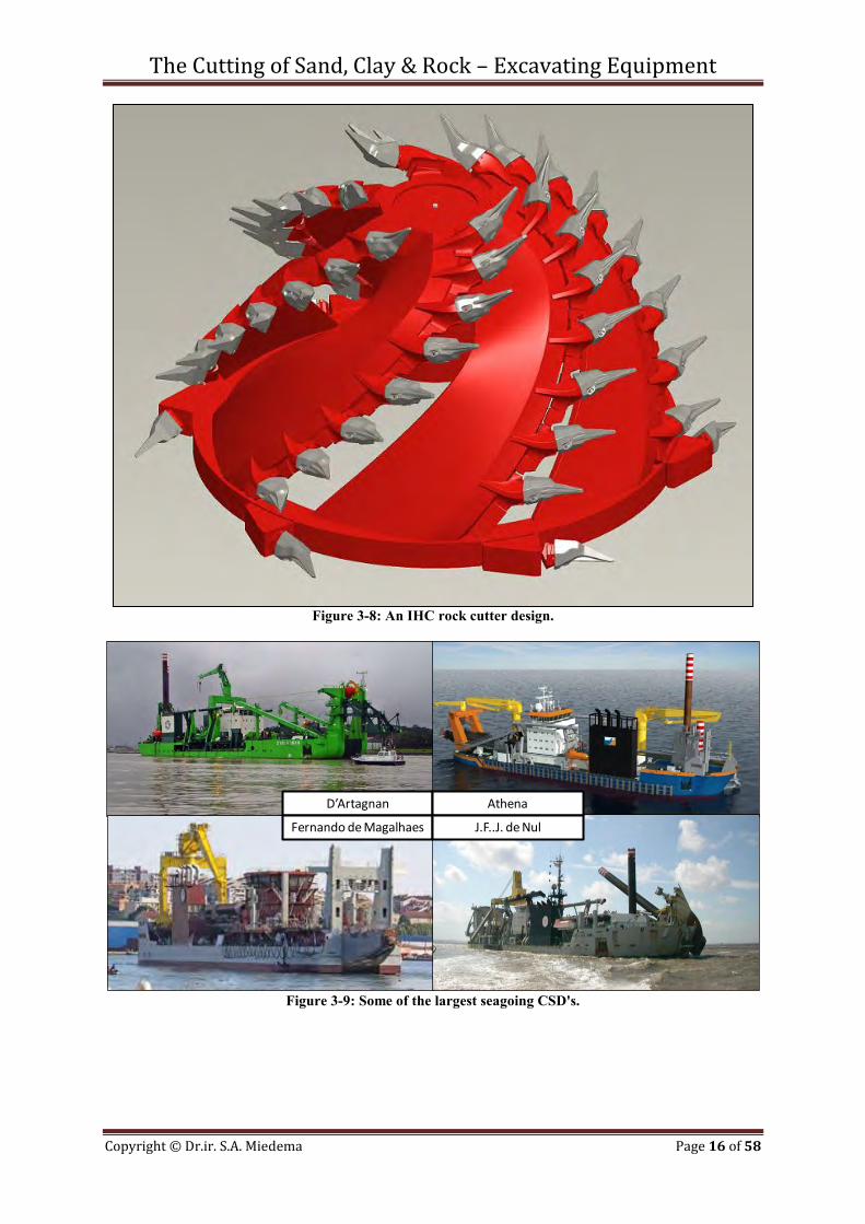
Figure 3-8: An IHC rock cutter design.
Figure 3-9: Some of the largest seagoing CSD's.
D’Artagnan Athena
Fernando de Magalhaes J.F..J. de Nul
The Cutting of Sand, Clay & Rock – Excavating Equipment
Copyright © Dr.ir. S.A. Miedema Page 17 of 58
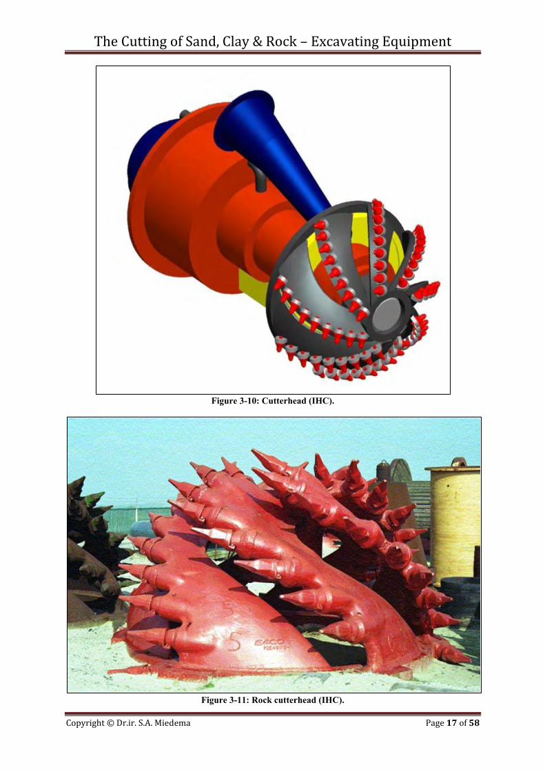
Figure 3-10: Cutterhead (IHC).
Figure 3-11: Rock cutterhead (IHC).

The Cutting of Sand, Clay & Rock – Excavating Equipment
Copyright © Dr.ir. S.A. Miedema Page 18 of 58
The Cutting of Sand, Clay & Rock – Excavating Equipment
Copyright © Dr.ir. S.A. Miedema Page 19 of 58
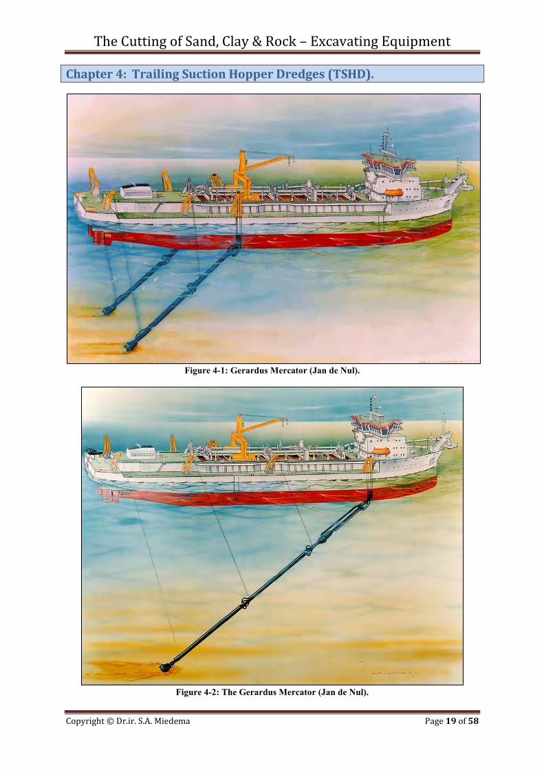
Chapter 4: Trailing Suction Hopper Dredges (TSHD).
Figure 4-1: Gerardus Mercator (Jan de Nul).
Figure 4-2: The Gerardus Mercator (Jan de Nul).
The Cutting of Sand, Clay & Rock – Excavating Equipment
Copyright © Dr.ir. S.A. Miedema Page 20 of 58
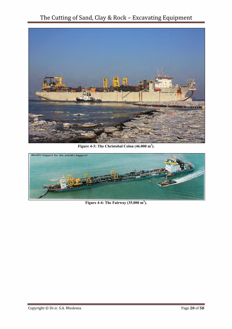
Figure 4-3: The Christobal Colon (46.000 m3).
Figure 4-4: The Fairway (35.000 m3).
The Cutting of Sand, Clay & Rock – Excavating Equipment
Copyright © Dr.ir. S.A. Miedema Page 21 of 58
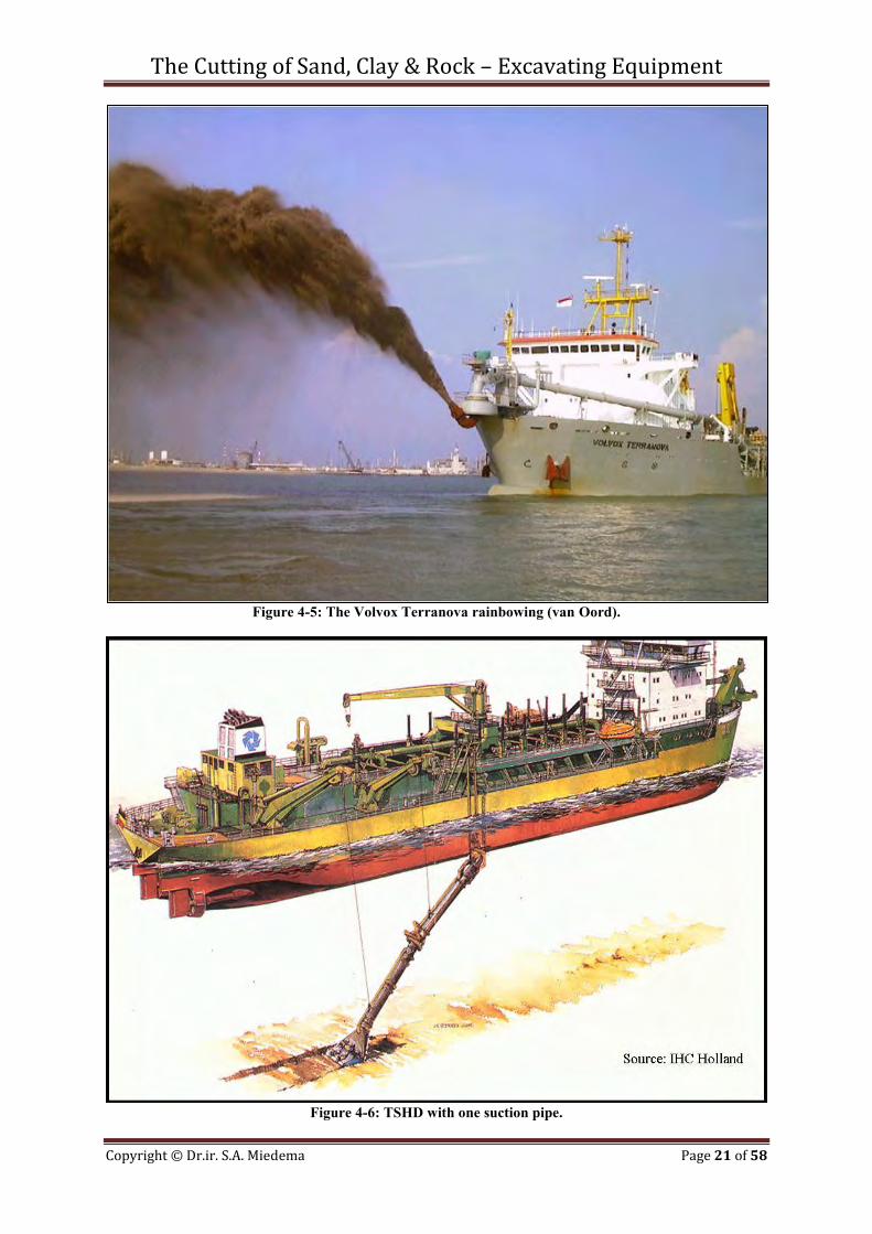
Figure 4-5: The Volvox Terranova rainbowing (van Oord).
Figure 4-6: TSHD with one suction pipe.
The Cutting of Sand, Clay & Rock – Excavating Equipment
Copyright © Dr.ir. S.A. Miedema Page 22 of 58
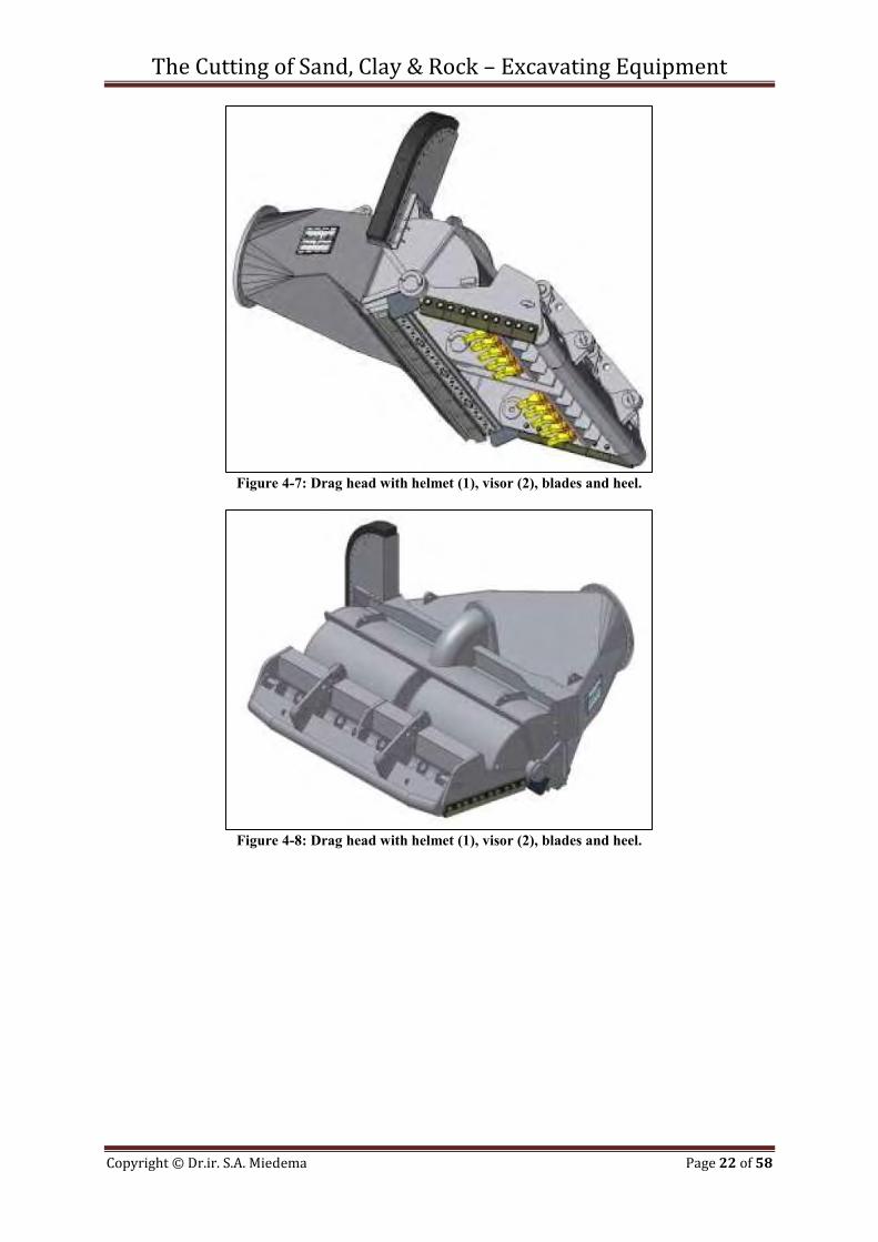
Figure 4-7: Drag head with helmet (1), visor (2), blades and heel.
Figure 4-8: Drag head with helmet (1), visor (2), blades and heel.
The Cutting of Sand, Clay & Rock – Excavating Equipment
Copyright © Dr.ir. S.A. Miedema Page 23 of 58
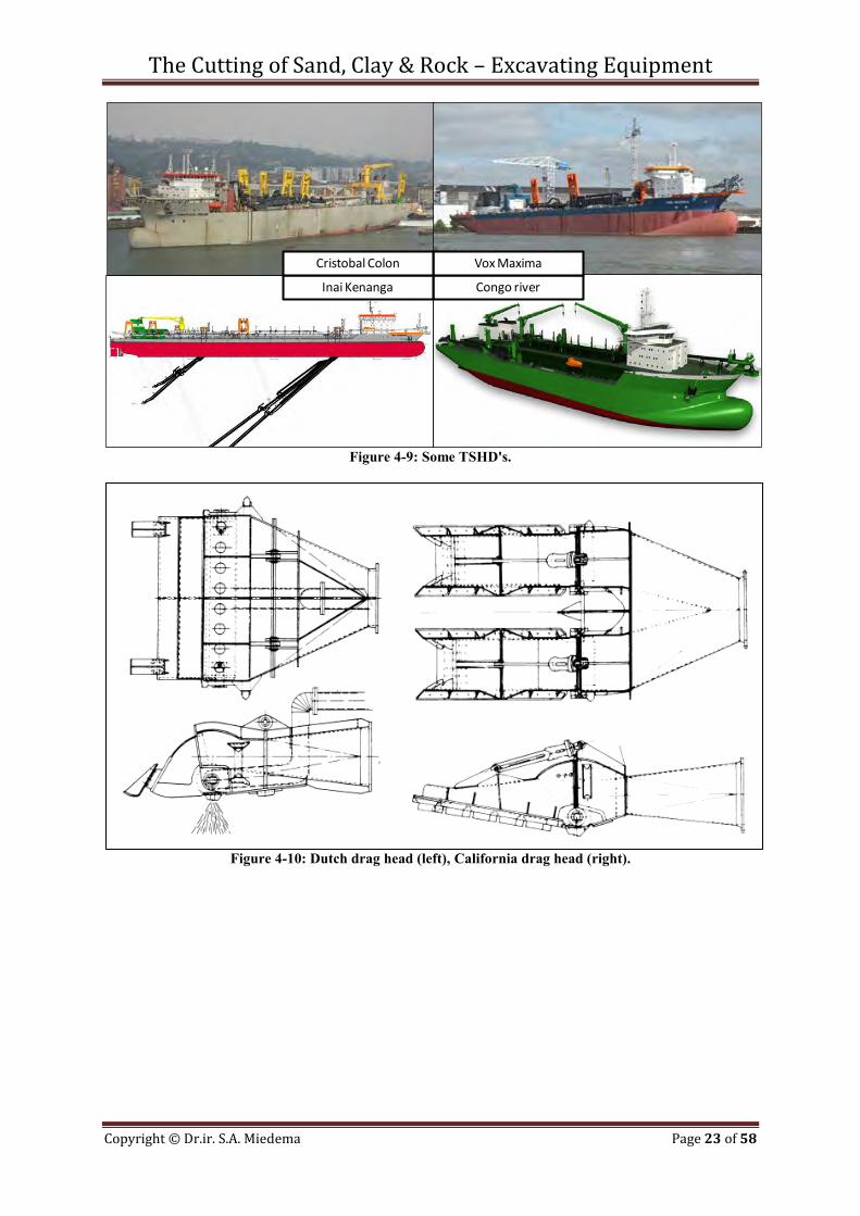
Figure 4-9: Some TSHD's.
Figure 4-10: Dutch drag head (left), California drag head (right).
Congo river
Vox Maxima
Inai Kenanga
Cristobal Colon

The Cutting of Sand, Clay & Rock – Excavating Equipment
Copyright © Dr.ir. S.A. Miedema Page 24 of 58
The Cutting of Sand, Clay & Rock – Excavating Equipment
Copyright © Dr.ir. S.A. Miedema Page 25 of 58
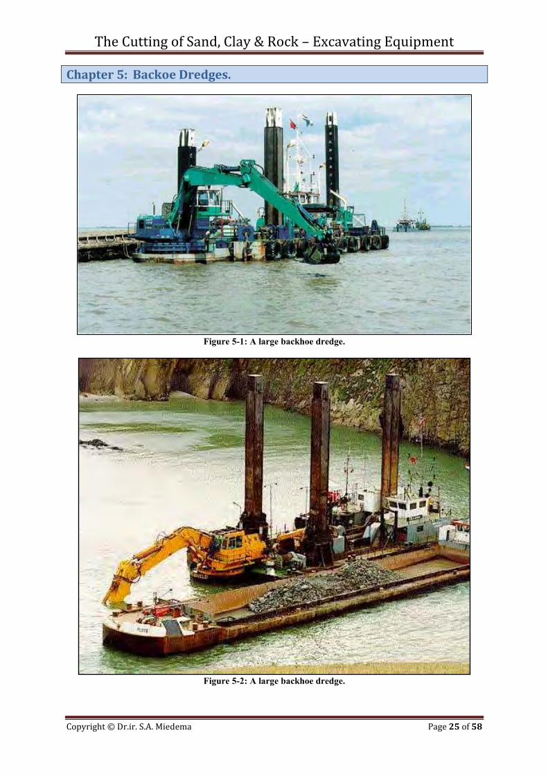
Chapter 5: Backoe Dredges.
Figure 5-1: A large backhoe dredge.
Figure 5-2: A large backhoe dredge.
The Cutting of Sand, Clay & Rock – Excavating Equipment
Copyright © Dr.ir. S.A. Miedema Page 26 of 58
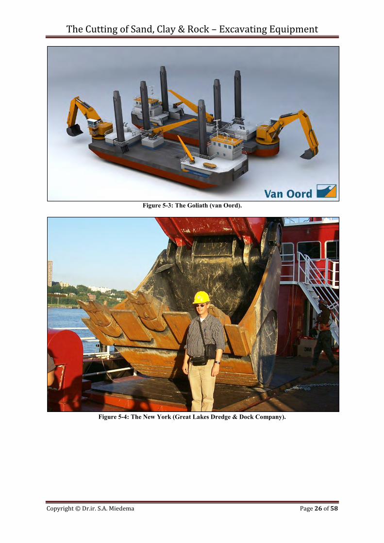
Figure 5-3: The Goliath (van Oord).
Figure 5-4: The New York (Great Lakes Dredge & Dock Company).
The Cutting of Sand, Clay & Rock – Excavating Equipment
Copyright © Dr.ir. S.A. Miedema Page 27 of 58
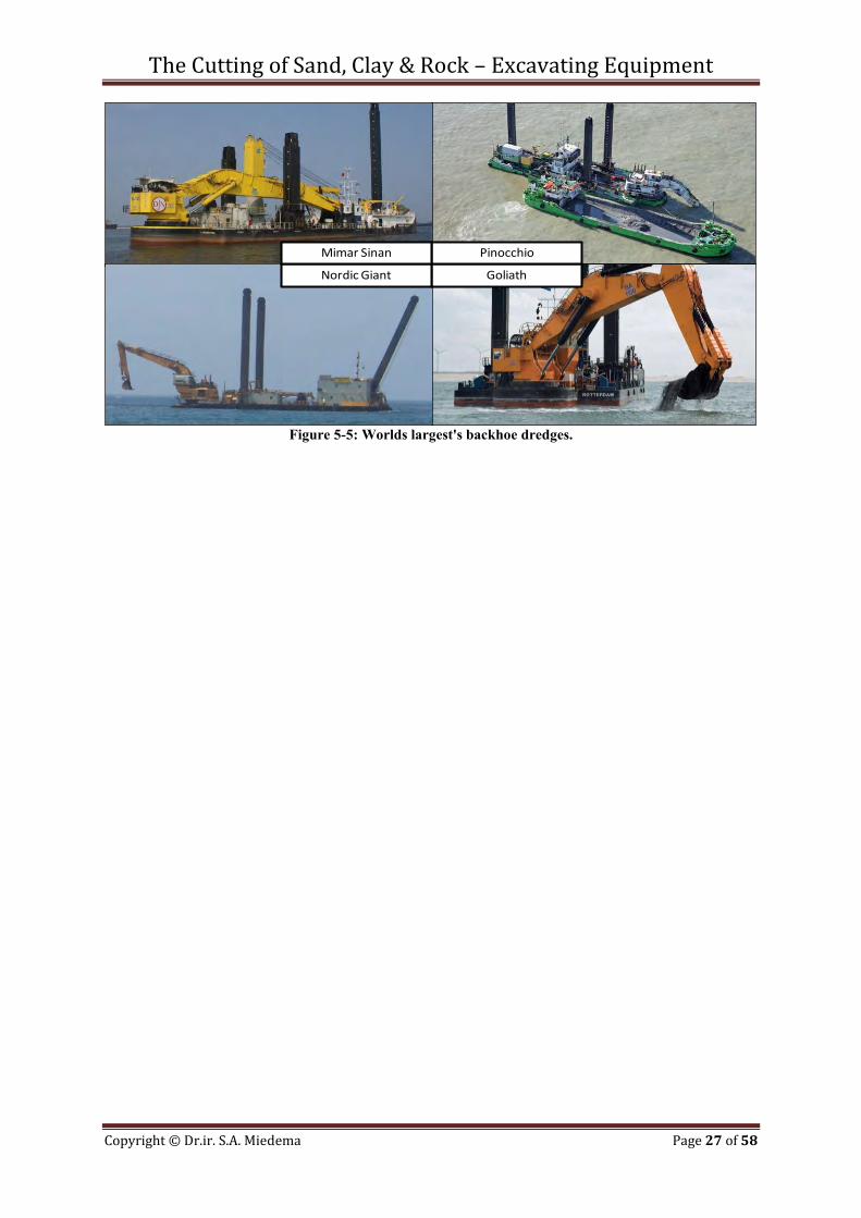
Figure 5-5: Worlds largest's backhoe dredges.
Goliath
Pinocchio
Nordic Giant
Mimar Sinan

The Cutting of Sand, Clay & Rock – Excavating Equipment
Copyright © Dr.ir. S.A. Miedema Page 28 of 58
The Cutting of Sand, Clay & Rock – Excavating Equipment
Copyright © Dr.ir. S.A. Miedema Page 29 of 58
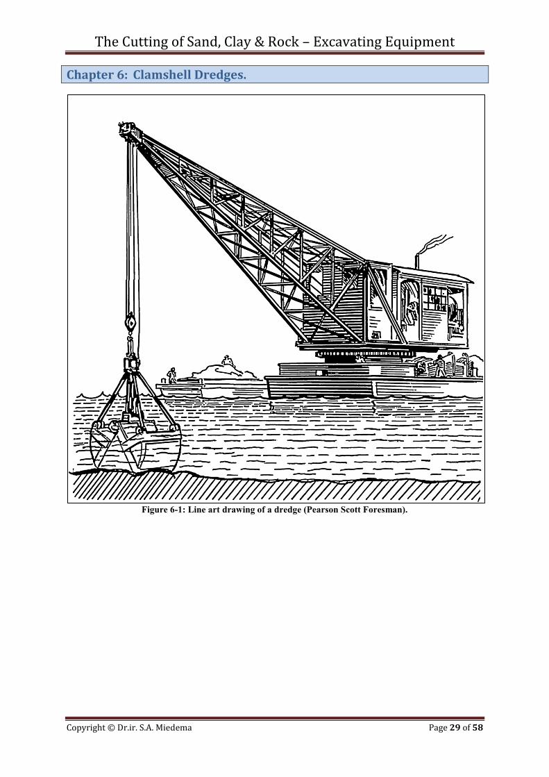
Chapter 6: Clamshell Dredges.
Figure 6-1: Line art drawing of a dredge (Pearson Scott Foresman).
The Cutting of Sand, Clay & Rock – Excavating Equipment
Copyright © Dr.ir. S.A. Miedema Page 30 of 58
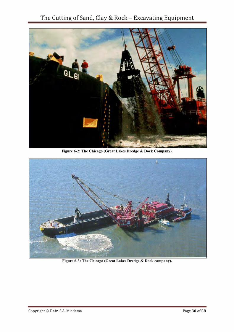
Figure 6-2: The Chicago (Great Lakes Dredge & Dock Company).
Figure 6-3: The Chicago (Great Lakes Dredge & Dock company).
The Cutting of Sand, Clay & Rock – Excavating Equipment
Copyright © Dr.ir. S.A. Miedema Page 31 of 58
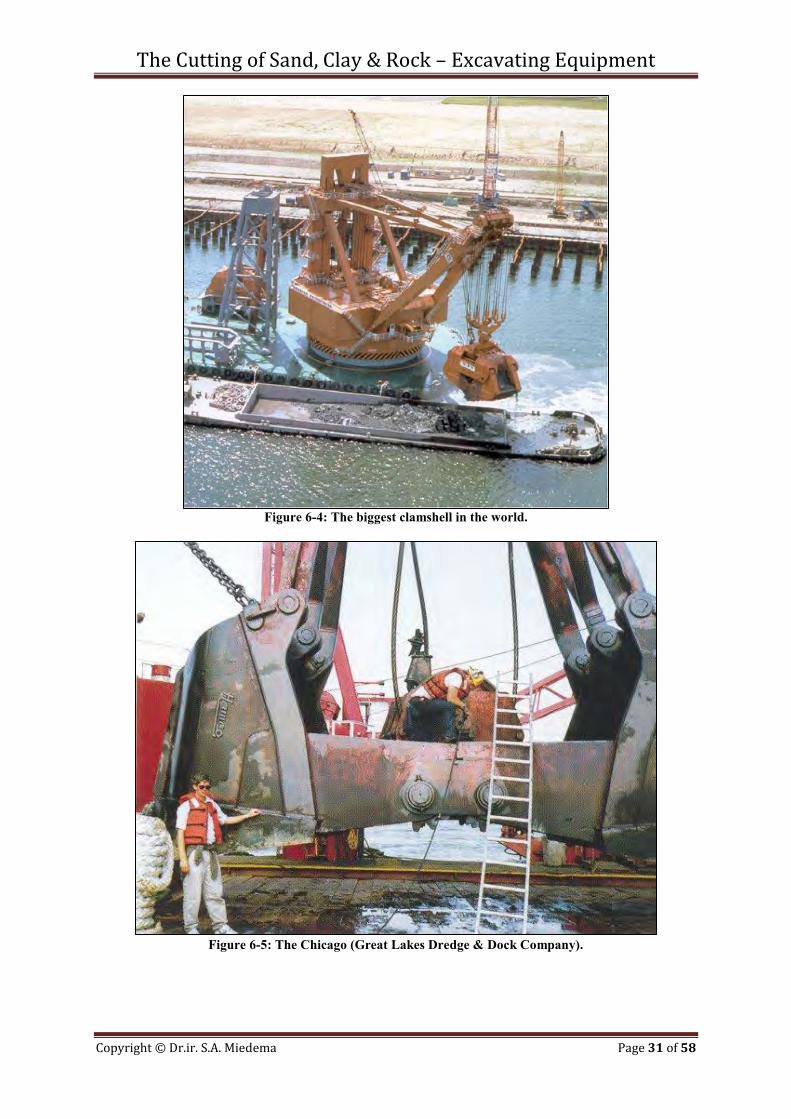
Figure 6-4: The biggest clamshell in the world.
Figure 6-5: The Chicago (Great Lakes Dredge & Dock Company).
The Cutting of Sand, Clay & Rock – Excavating Equipment
Copyright © Dr.ir. S.A. Miedema Page 32 of 58
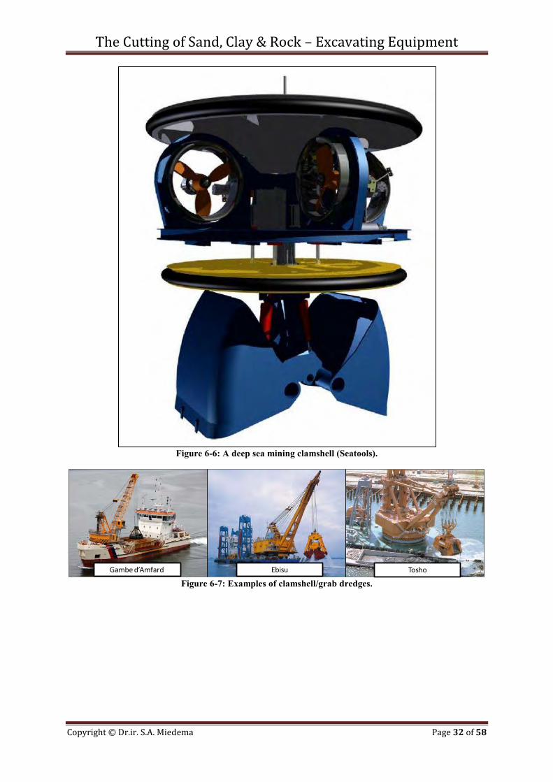
Figure 6-6: A deep sea mining clamshell (Seatools).
Figure 6-7: Examples of clamshell/grab dredges.
Gambed’Amfard ToshoEbisu
The Cutting of Sand, Clay & Rock – Excavating Equipment
Copyright © Dr.ir. S.A. Miedema Page 33 of 58
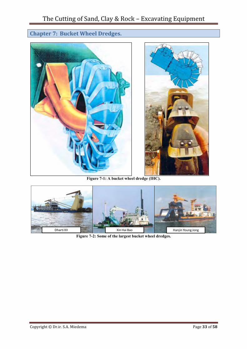
Chapter 7: Bucket Wheel Dredges.
Figure 7-1: A bucket wheel dredge (IHC).
Figure 7-2: Some of the largest bucket wheel dredges.
Dharti XII Hanjin Young JongXin Hai Bao
The Cutting of Sand, Clay & Rock – Excavating Equipment
Copyright © Dr.ir. S.A. Miedema Page 34 of 58
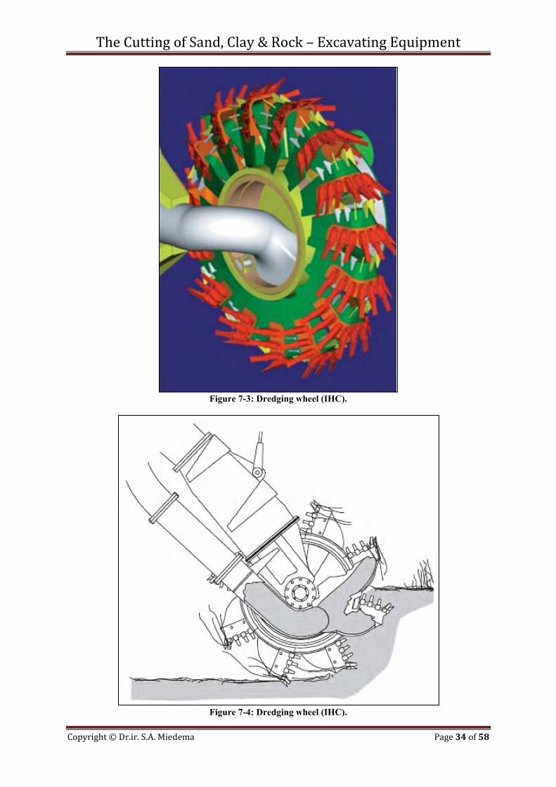
Figure 7-3: Dredging wheel (IHC).
Figure 7-4: Dredging wheel (IHC).
The Cutting of Sand, Clay & Rock – Excavating Equipment
Copyright © Dr.ir. S.A. Miedema Page 35 of 58
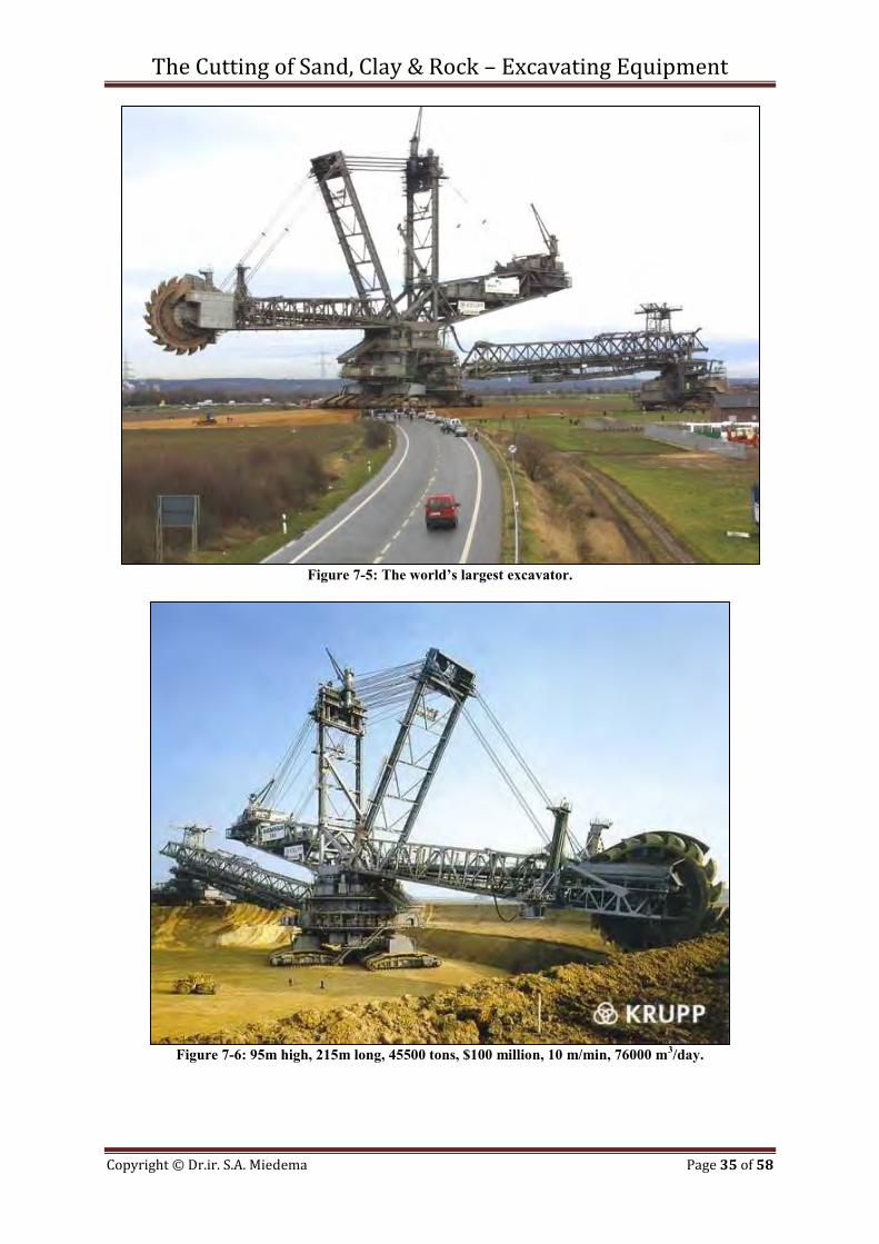
Figure 7-5: The world’s largest excavator.
Figure 7-6: 95m high, 215m long, 45500 tons, $100 million, 10 m/min, 76000 m3/day.

The Cutting of Sand, Clay & Rock – Excavating Equipment
Copyright © Dr.ir. S.A. Miedema Page 36 of 58
The Cutting of Sand, Clay & Rock – Excavating Equipment
Copyright © Dr.ir. S.A. Miedema Page 37 of 58
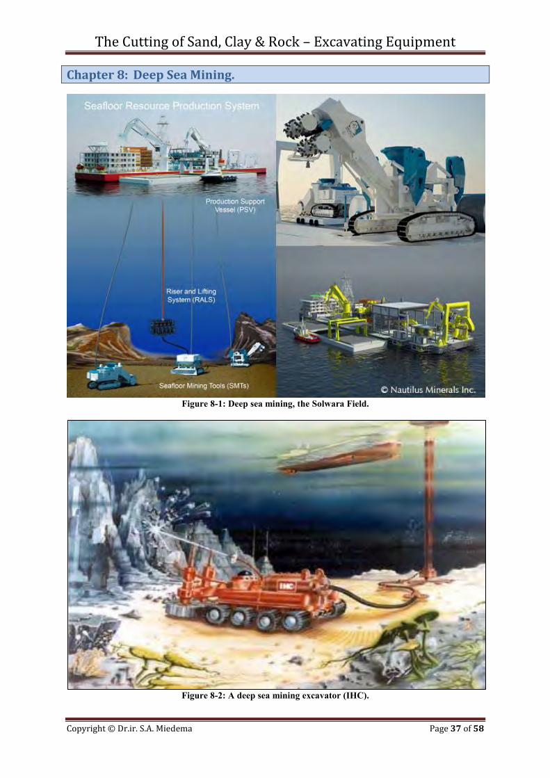
Chapter 8: Deep Sea Mining.
Figure 8-1: Deep sea mining, the Solwara Field.
Figure 8-2: A deep sea mining excavator (IHC).
The Cutting of Sand, Clay & Rock – Excavating Equipment
Copyright © Dr.ir. S.A. Miedema Page 38 of 58
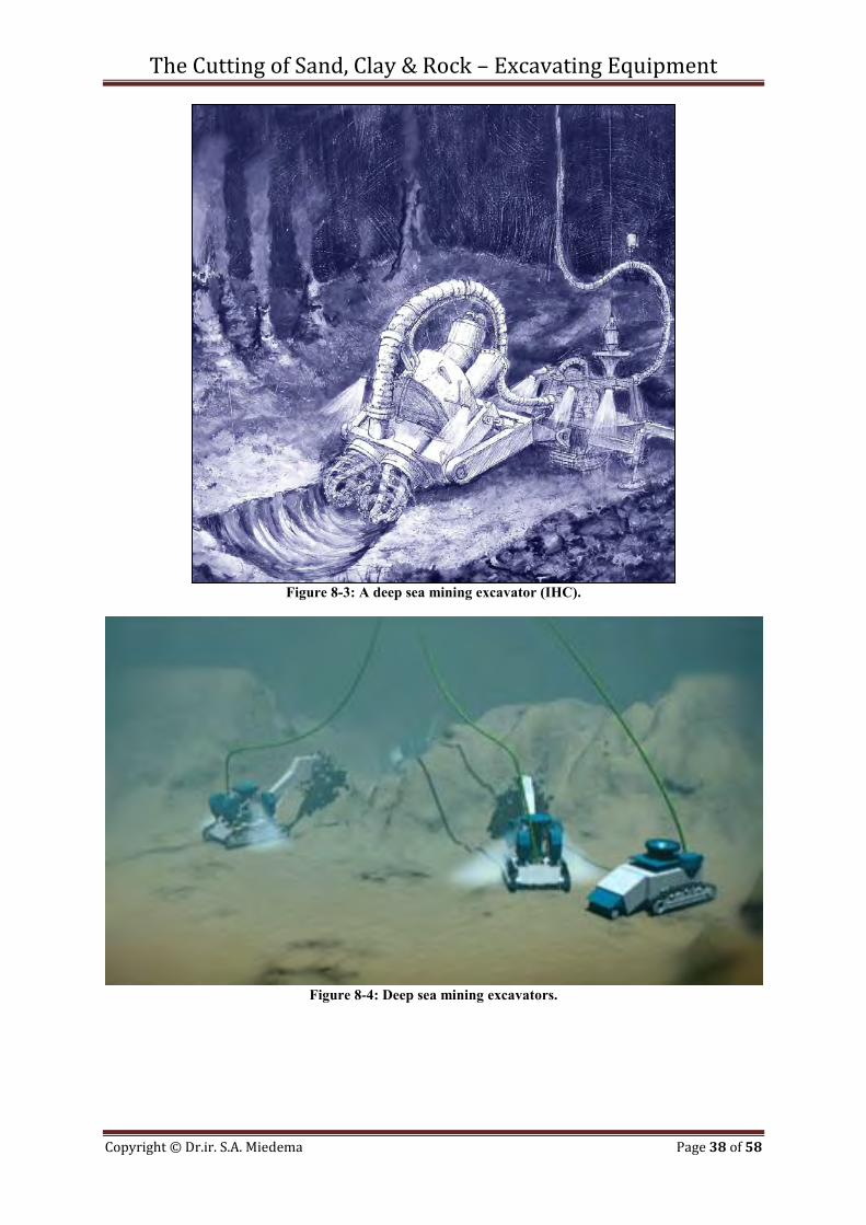
Figure 8-3: A deep sea mining excavator (IHC).
Figure 8-4: Deep sea mining excavators.
The Cutting of Sand, Clay & Rock – Excavating Equipment
Copyright © Dr.ir. S.A. Miedema Page 39 of 58
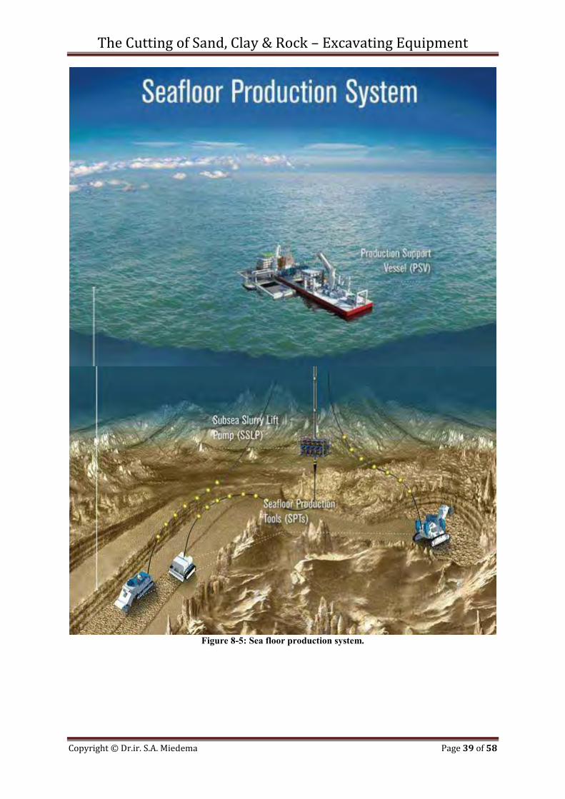
Figure 8-5: Sea floor production system.

The Cutting of Sand, Clay & Rock – Excavating Equipment
Copyright © Dr.ir. S.A. Miedema Page 40 of 58
The Cutting of Sand, Clay & Rock – Excavating Equipment
Copyright © Dr.ir. S.A. Miedema Page 41 of 58
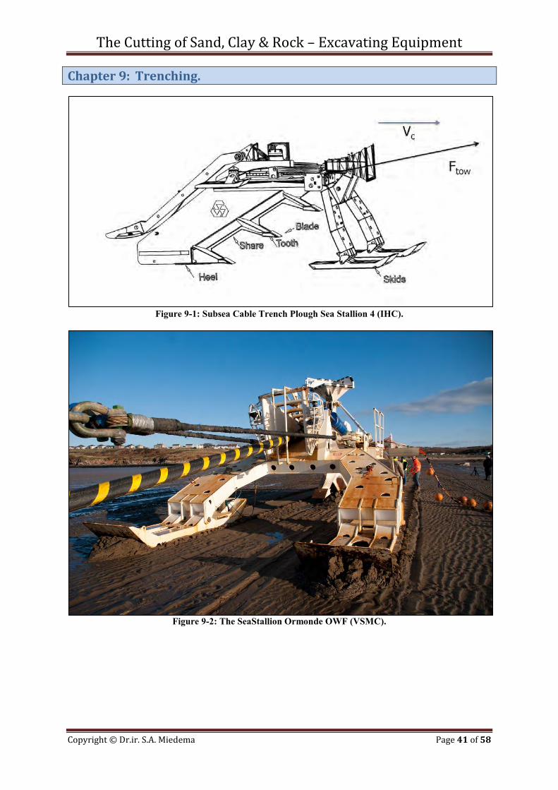
Chapter 9: Trenching.
Figure 9-1: Subsea Cable Trench Plough Sea Stallion 4 (IHC).
Figure 9-2: The SeaStallion Ormonde OWF (VSMC).
The Cutting of Sand, Clay & Rock – Excavating Equipment
Copyright © Dr.ir. S.A. Miedema Page 42 of 58
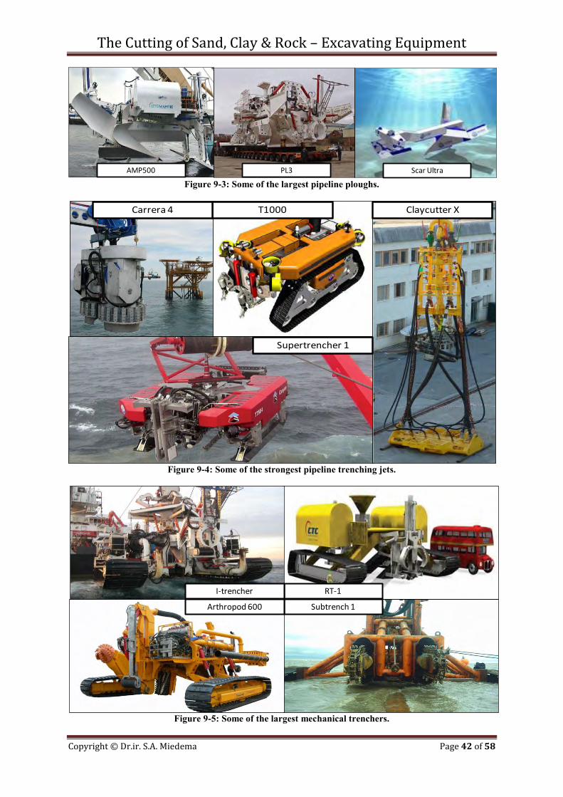
Figure 9-3: Some of the largest pipeline ploughs.
Figure 9-4: Some of the strongest pipeline trenching jets.
Figure 9-5: Some of the largest mechanical trenchers.
AMP500 Scar UltraPL3
Claycutter XT1000
Supertrencher 1
Carrera 4
Subtrench 1
RT-1
Arthropod 600
I-trencher
The Cutting of Sand, Clay & Rock – Excavating Equipment
Copyright © Dr.ir. S.A. Miedema Page 43 of 58
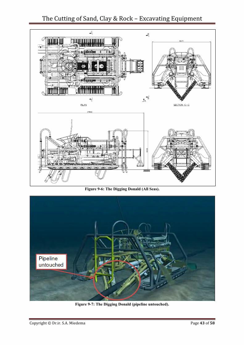
Figure 9-6: The Digging Donald (All Seas).
Figure 9-7: The Digging Donald (pipeline untouched).
The Cutting of Sand, Clay & Rock – Excavating Equipment
Copyright © Dr.ir. S.A. Miedema Page 44 of 58
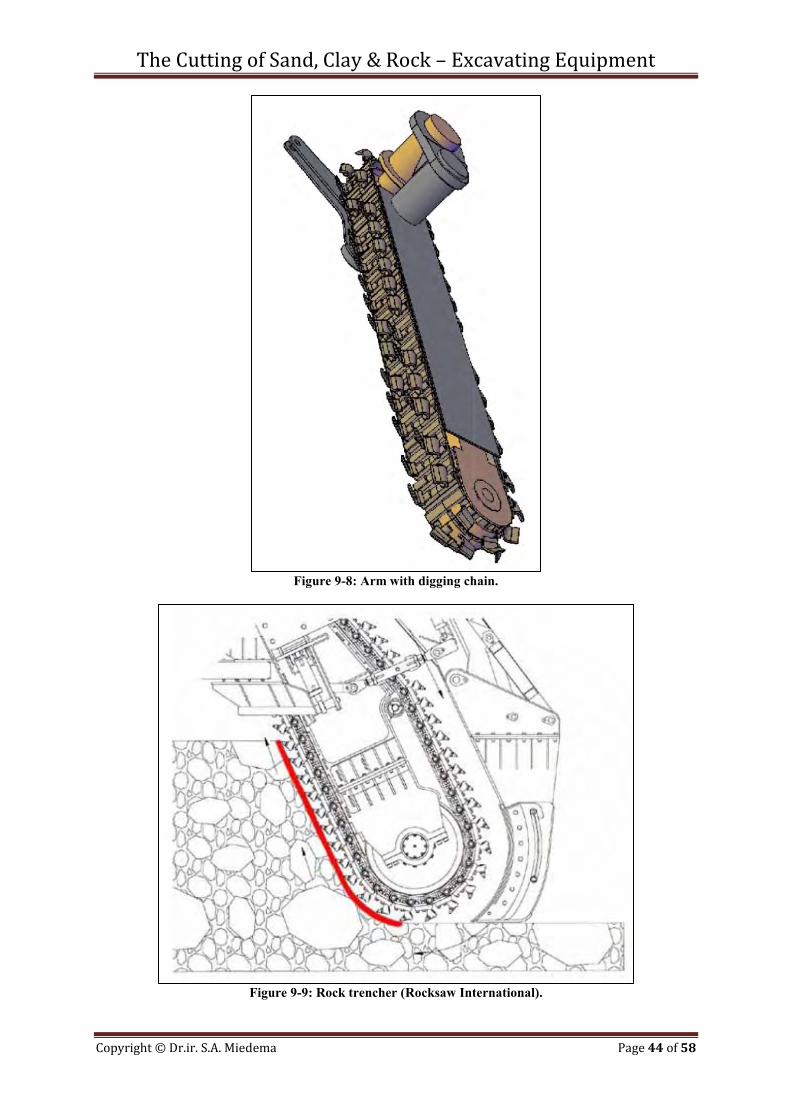
Figure 9-8: Arm with digging chain.
Figure 9-9: Rock trencher (Rocksaw International).

The Cutting of Sand, Clay & Rock – Excavating Equipment
Copyright © Dr.ir. S.A. Miedema Page 45 of 58
Figure 9-10: Rock trencher (Rocksaw International).

The Cutting of Sand, Clay & Rock – Excavating Equipment
Copyright © Dr.ir. S.A. Miedema Page 46 of 58
The Cutting of Sand, Clay & Rock – Excavating Equipment
Copyright © Dr.ir. S.A. Miedema Page 47 of 58
Chapter 10: PDC Cutters.
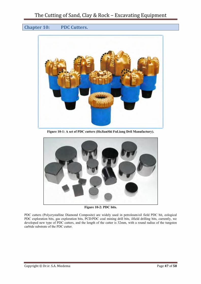
Figure 10-1: A set of PDC cutters (HeJianShi FuLiang Dril Manufactury).
Figure 10-2: PDC bits.
PDC cutters (Polycrystalline Diamond Composite) are widely used in petroleum/oil field PDC bit, eological PDC exploration bits, gas exploration bits, PCD/PDC coal mining drill bits, ilfield drilling bits, currently, we developed new type of PDC cutters, and the length of the cutter is 32mm, with a round radius of the tungsten carbide substrate of the PDC cutter.
The Cutting of Sand, Clay & Rock – Excavating Equipment
Copyright © Dr.ir. S.A. Miedema Page 48 of 58
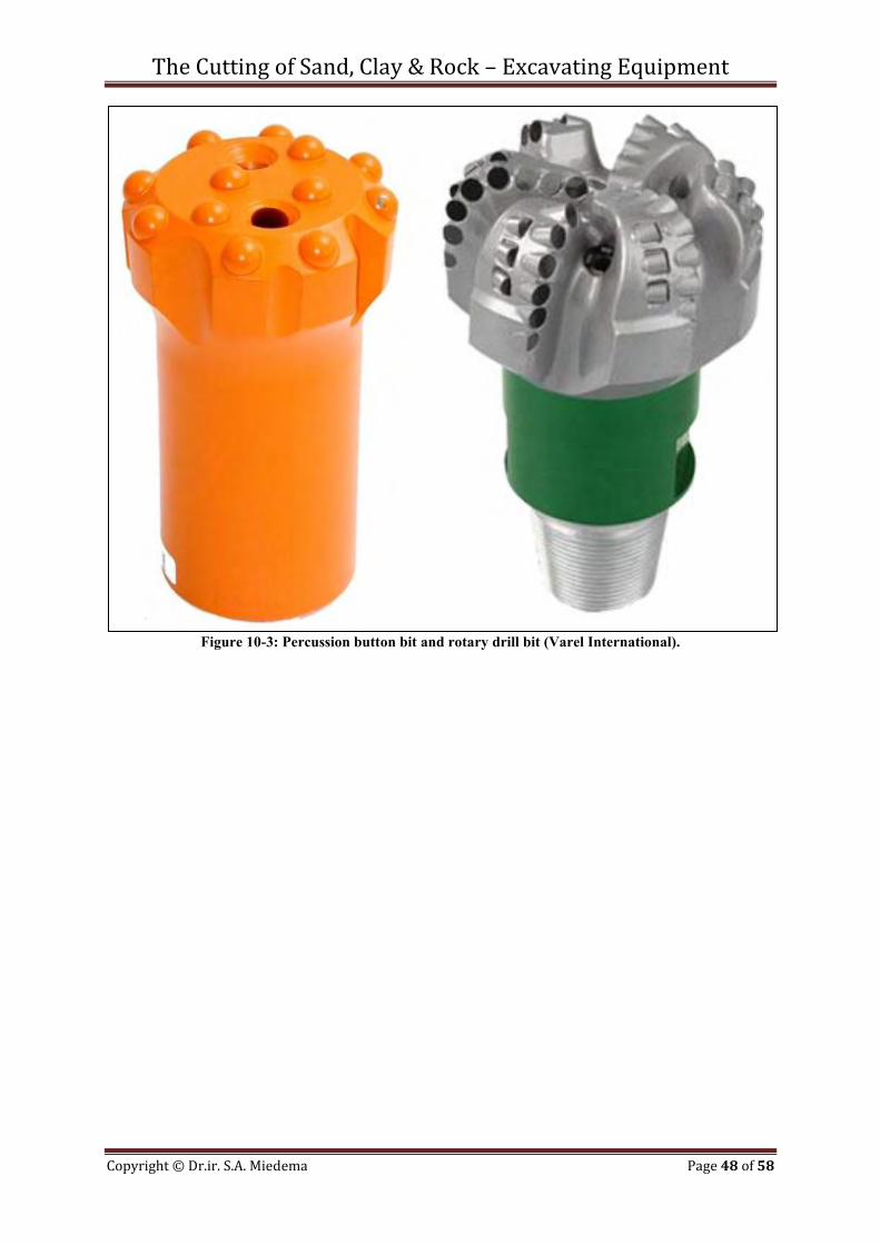
Figure 10-3: Percussion button bit and rotary drill bit (Varel International).
The Cutting of Sand, Clay & Rock – Excavating Equipment
Copyright © Dr.ir. S.A. Miedema Page 49 of 58
Chapter 11: Dry Mining/TBM.
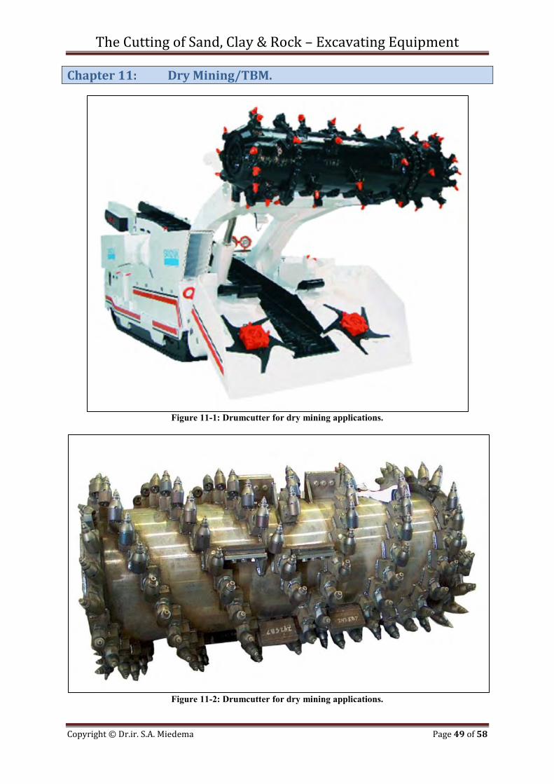
Figure 11-1: Drumcutter for dry mining applications.
Figure 11-2: Drumcutter for dry mining applications.
The Cutting of Sand, Clay & Rock – Excavating Equipment
Copyright © Dr.ir. S.A. Miedema Page 50 of 58
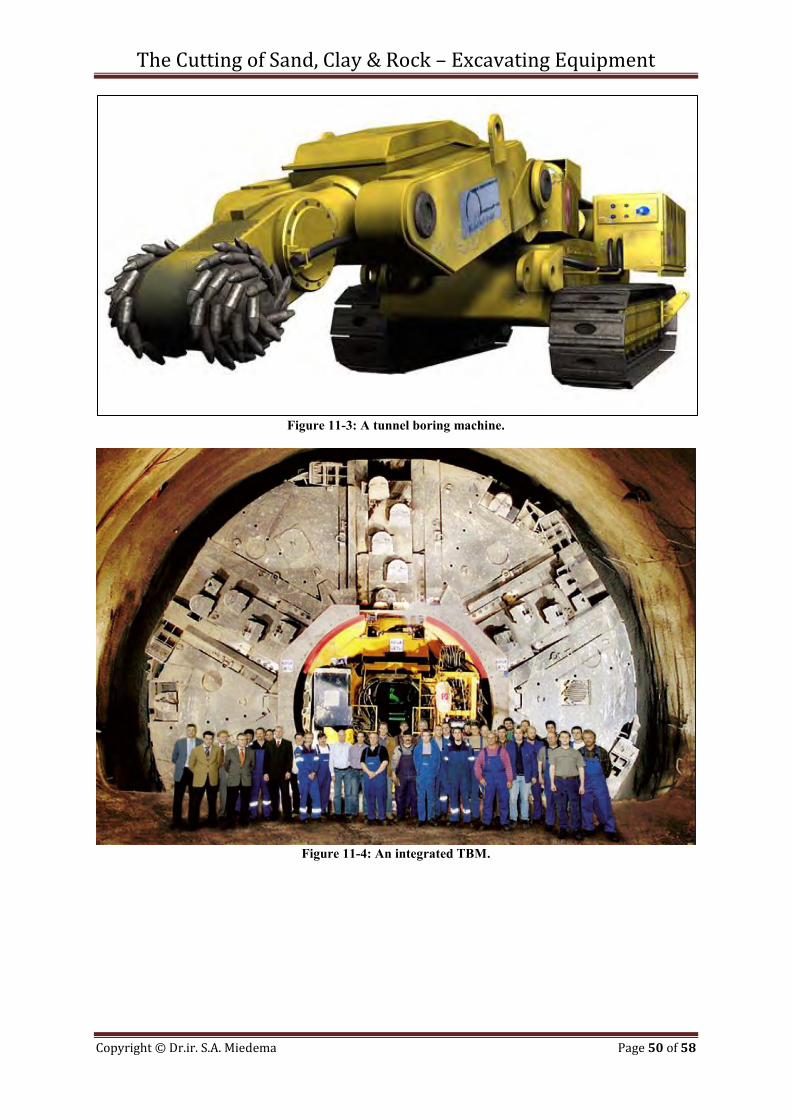
Figure 11-3: A tunnel boring machine.
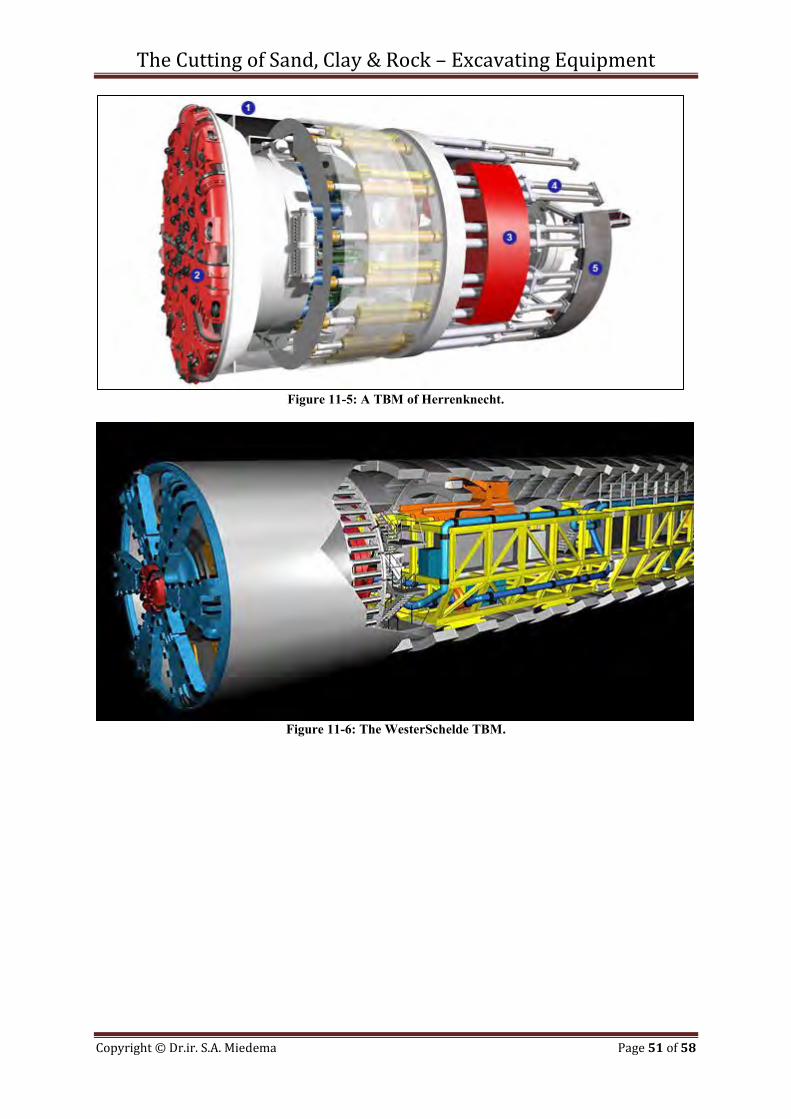
Figure 11-4: An integrated TBM.
The Cutting of Sand, Clay & Rock – Excavating Equipment
Copyright © Dr.ir. S.A. Miedema Page 51 of 58
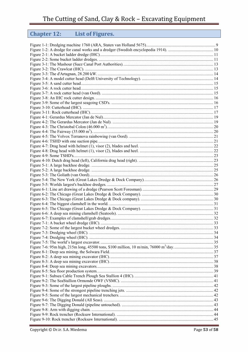
Figure 11-5: A TBM of Herrenknecht.
Figure 11-6: The WesterSchelde TBM.

The Cutting of Sand, Clay & Rock – Excavating Equipment
Copyright © Dr.ir. S.A. Miedema Page 52 of 58
The Cutting of Sand, Clay & Rock – Excavating Equipment
Copyright © Dr.ir. S.A. Miedema Page 53 of 58
Chapter 12: List of Figures. Figure 1-1: Dredging machine 1760 (ARA, Staten van Holland 5675). ................................................................. 9 Figure 1-2: A dredge for canal works and a dredger (Swedish encyclopedia 1914). ........................................... 10 Figure 2-1: A bucket ladder dredge (IHC). ........................................................................................................... 11 Figure 2-2: Some bucket ladder dredges. ............................................................................................................. 11 Figure 3-1: The Mashour (Suez Canal Port Authorities). ..................................................................................... 13 Figure 3-2: The Crawlcat (IHC). .......................................................................................................................... 13 Figure 3-3: The d'Artagnan, 28.200 kW. .............................................................................................................. 14 Figure 3-4: A model cutter head (Delft University of Technology). .................................................................... 14 Figure 3-5: A sand cutter head. ............................................................................................................................. 15 Figure 3-6: A rock cutter head. ............................................................................................................................. 15 Figure 3-7: A rock cutter head (van Oord). .......................................................................................................... 15 Figure 3-8: An IHC rock cutter design. ................................................................................................................ 16 Figure 3-9: Some of the largest seagoing CSD's. ................................................................................................. 16 Figure 3-10: Cutterhead (IHC). ............................................................................................................................ 17 Figure 3-11: Rock cutterhead (IHC). .................................................................................................................... 17 Figure 4-1: Gerardus Mercator (Jan de Nul). ........................................................................................................ 19 Figure 4-2: The Gerardus Mercator (Jan de Nul). ................................................................................................ 19 Figure 4-3: The Christobal Colon (46.000 m3). .................................................................................................... 20 Figure 4-4: The Fairway (35.000 m3). .................................................................................................................. 20 Figure 4-5: The Volvox Terranova rainbowing (van Oord). ................................................................................ 21 Figure 4-6: TSHD with one suction pipe. ............................................................................................................. 21 Figure 4-7: Drag head with helmet (1), visor (2), blades and heel. ...................................................................... 22 Figure 4-8: Drag head with helmet (1), visor (2), blades and heel. ...................................................................... 22 Figure 4-9: Some TSHD's. .................................................................................................................................... 23 Figure 4-10: Dutch drag head (left), California drag head (right). ....................................................................... 23 Figure 5-1: A large backhoe dredge. .................................................................................................................... 25 Figure 5-2: A large backhoe dredge. .................................................................................................................... 25 Figure 5-3: The Goliath (van Oord). ..................................................................................................................... 26 Figure 5-4: The New York (Great Lakes Dredge & Dock Company). ................................................................. 26 Figure 5-5: Worlds largest's backhoe dredges. ..................................................................................................... 27 Figure 6-1: Line art drawing of a dredge (Pearson Scott Foresman). ................................................................... 29 Figure 6-2: The Chicago (Great Lakes Dredge & Dock Company). .................................................................... 30 Figure 6-3: The Chicago (Great Lakes Dredge & Dock company). ..................................................................... 30 Figure 6-4: The biggest clamshell in the world. ................................................................................................... 31 Figure 6-5: The Chicago (Great Lakes Dredge & Dock Company). .................................................................... 31 Figure 6-6: A deep sea mining clamshell (Seatools). ........................................................................................... 32 Figure 6-7: Examples of clamshell/grab dredges. ................................................................................................. 32 Figure 7-1: A bucket wheel dredge (IHC). ........................................................................................................... 33 Figure 7-2: Some of the largest bucket wheel dredges. ........................................................................................ 33 Figure 7-3: Dredging wheel (IHC). ...................................................................................................................... 34 Figure 7-4: Dredging wheel (IHC). ...................................................................................................................... 34 Figure 7-5: The world’s largest excavator. ........................................................................................................... 35 Figure 7-6: 95m high, 215m long, 45500 tons, $100 million, 10 m/min, 76000 m3/day. ..................................... 35 Figure 8-1: Deep sea mining, the Solwara Field. .................................................................................................. 37 Figure 8-2: A deep sea mining excavator (IHC). .................................................................................................. 37 Figure 8-3: A deep sea mining excavator (IHC). .................................................................................................. 38 Figure 8-4: Deep sea mining excavators. .............................................................................................................. 38 Figure 8-5: Sea floor production system. .............................................................................................................. 39 Figure 9-1: Subsea Cable Trench Plough Sea Stallion 4 (IHC). ........................................................................... 41 Figure 9-2: The SeaStallion Ormonde OWF (VSMC). ........................................................................................ 41 Figure 9-3: Some of the largest pipeline ploughs. ................................................................................................ 42 Figure 9-4: Some of the strongest pipeline trenching jets. ................................................................................... 42 Figure 9-5: Some of the largest mechanical trenchers. ......................................................................................... 42 Figure 9-6: The Digging Donald (All Seas). ........................................................................................................ 43 Figure 9-7: The Digging Donald (pipeline untouched). ....................................................................................... 43 Figure 9-8: Arm with digging chain. .................................................................................................................... 44 Figure 9-9: Rock trencher (Rocksaw International). ............................................................................................ 44 Figure 9-10: Rock trencher (Rocksaw International). .......................................................................................... 45
The Cutting of Sand, Clay & Rock – Excavating Equipment
Copyright © Dr.ir. S.A. Miedema Page 54 of 58
Figure 10-1: A set of PDC cutters (HeJianShi FuLiang Dril Manufactury). ........................................................ 47 Figure 10-2: PDC bits. .......................................................................................................................................... 47 Figure 10-3: Percussion button bit and rotary drill bit (Varel International). ....................................................... 48 Figure 11-1: Drumcutter for dry mining applications. .......................................................................................... 49 Figure 11-2: Drumcutter for dry mining applications. .......................................................................................... 49 Figure 11-3: A tunnel boring machine. ................................................................................................................. 50 Figure 11-4: An integrated TBM. ......................................................................................................................... 50 Figure 11-5: A TBM of Herrenknecht. ................................................................................................................. 51 Figure 11-6: The WesterSchelde TBM. ................................................................................................................ 51
The Cutting of Sand, Clay & Rock – Excavating Equipment
Copyright © Dr.ir. S.A. Miedema Page 55 of 58
Dredging Processes The Cutting of Sand, Clay & Rock
Excavating Equipment
The Cutting of Sand, Clay & Rock – Excavating Equipment
Copyright © Dr.ir. S.A. Miedema Page 56 of 58
The Cutting of Sand, Clay & Rock – Excavating Equipment
Copyright © Dr.ir. S.A. Miedema Page 57 of 58
Chapter 13: About the Author.
Dr.ir. Sape A. Miedema (November 8th 1955) obtained his M.Sc. degree in Mechanical Engineering with honours at the Delft University of Technology (DUT) in 1983. He obtained his Ph.D. degree on research into the basics of soil cutting in relation with ship motions, in 1987. From 1987 to 1992 he was assistant professor at the chair of Dredging Technology. In 1992 and 1993 he was a member of the management board of Mechanical Engineering & Marine Technology of the DUT. In 1992 he became associate professor at the DUT with the chair of Dredging Technology. From 1996 to 2001 he was appointed educational director of Mechanical Engineering and Marine Technology at the DUT, but still remaining associate professor of Dredging Engineering. In 2005 he was appointed educational director of the MSc program of Offshore Engineering and he is also still asscoiate professor of Dredging Engineering. In 2011 he was also appointed as director of the MSc program Offshore Engineering of the Petrovietnam University. Dr.ir. S.A. Miedema teaches (or has taught) courses on soil mechanics and soil cutting, hopper sedimentation, mechatronics, applied thermodynamics, drive system design principles, mooring systems and mathematics. His research focuses on the mathematical modeling of dredging systems like, cutter suction dredges, hopper dredges, clamshell dredges, backhoe dredges and trenchers. The fundamental part of the research focuses on the cutting processes of sand, clay and rock, sedimentation processes in Trailing Suction Hopper Dredges and the associated erosion processes. Lately the research focuses on hyperbaric rock cutting in relation with deep sea mining and on hydraulic transport of sand/water slurries.
The Cutting of Sand, Clay & Rock – Excavating Equipment
Copyright © Dr.ir. S.A. Miedema Page 58 of 58
Dredging Processes The Cutting of Sand, Clay & Rock
Excavating Equipment
By
Dr.ir. Sape A. Miedema In dredging, trenching, (deep sea) mining, drilling, tunnel boring and many other applications, sand, clay or rock has to be excavated. The productions (and thus the dimensions) of the excavating equipment range from mm3/sec - cm3/sec to m3/sec. In oil drilling layers with a thickness of a magnitude of 0.2 mm are cut, while in dredging this can be of a magnitude of 0.1 m with cutter suction dredges and meters for clamshells and backhoe’s. Some equipment is designed for dry soil, while others operate under water saturated conditions. Installed cutting powers may range up to 10 MW. For both the design, the operation and production estimation of the excavating equipment it is important to be able to predict the cutting forces and powers. After the soil has been excavated it is usually transported hydraulically as a slurry over a short (TSHD’s) or a long distance (CSD’s). Estimating the pressure losses and determining whether or not a bed will occur in the pipeline is of great importance. Fundamental processes of sedimentation, initiation of motion and ersosion of the soil particles determine the transport process and the flow regimes. In TSHD’s the soil has to settle during the loading process, where also sedimentation and erosion will be in equilibrium. In all cases we have to deal with soil and high density soil water mixtures and its fundamental behavior. This book gives an overview of the equipment involved in cutting processes. This book will give engineers an impression of the diversity of the excavating equipment and is the 1st of 7 books. Part 1: The Cutting of Sand, Clay & Rock – Excavating Equipment Part 2: The Cutting of Sand, Clay & Rock – Soil Mechanics Part 3: The Cutting of Sand, Clay & Rock - Theory Part 4: The Loading Process of a Trailing Suction Hopper Dredge. Part 5: The Initiation of Motion of Particles.. Part 6: Hydraulic Transport – Theory. Part 7: Hydraulic Transport – Experiments.