Embed Size (px)
Citation preview


1
The Convergence ofAdvanced Technology and TraditionThe new FL200 was born out of Toyota’s unending pursuit of the ideal roving frame, one that enables anyone to spin
high-quality roving at high speeds, the aim of the original FL100.
The three-motor drive established in the FL100 has evolved and developed into a four-motor drive, and the latest in
servo technology and dramatically improved CPU performance provides even greater accuracy and control. New
intelligent features have been added to the FL200, enabling the machine to “think for itself” and become a detail-
oriented assistant facilitating the customer’s operations. Combined with the synergy of a high-performance tension
controller, the FL200 guarantees our customers a roving process one rank above all others in every aspect of
performance, including productivity, operability, and roving quality.
Newly Developed Four-Motor Drive• Main motor drives flyers• Draft motor drives bottom rollers• Winding motor drives bobbins• Lifting motor drives bobbin rail

2
10.4-inch color function panel
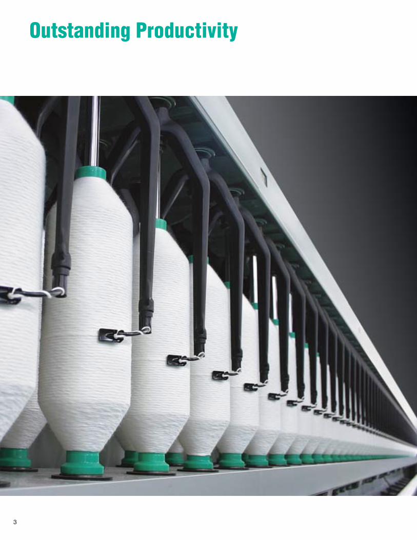
Outstanding Productivity
3
45 85650.4
0.5
0.6
0.7
0.8
0.9
1
1.1
1.2
1.3
1.4
70
60
50
40
30
20
10
0900800700600 1,000 1,200 1,3001,100 1,5001,400
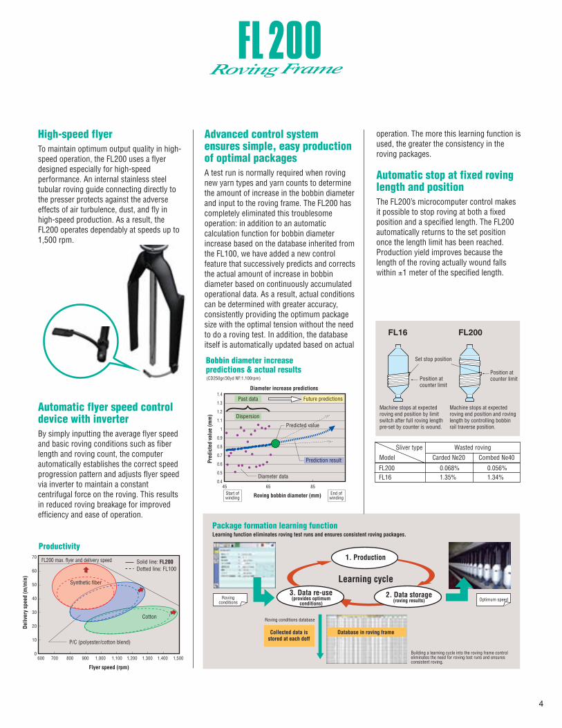
High-speed flyerTo maintain optimum output quality in high-speed operation, the FL200 uses a flyer designed especially for high-speed performance. An internal stainless steel tubular roving guide connecting directly to the presser protects against the adverse effects of air turbulence, dust, and fly in high-speed production. As a result, the FL200 operates dependably at speeds up to 1,500 rpm.
Advanced control system ensures simple, easy production of optimal packagesA test run is normally required when roving new yarn types and yarn counts to determine the amount of increase in the bobbin diameter and input to the roving frame. The FL200 has completely eliminated this troublesome operation: in addition to an automatic calculation function for bobbin diameter increase based on the database inherited from the FL100, we have added a new control feature that successively predicts and corrects the actual amount of increase in bobbin diameter based on continuously accumulated operational data. As a result, actual conditions can be determined with greater accuracy, consistently providing the optimum package size with the optimal tension without the need to do a roving test. In addition, the database itself is automatically updated based on actual
operation. The more this learning function is used, the greater the consistency in the roving packages.
Automatic stop at fixed roving length and positionThe FL200’s microcomputer control makes it possible to stop roving at both a fixed position and a specified length. The FL200 automatically returns to the set position once the length limit has been reached. Production yield improves because the length of the roving actually wound falls within ±1 meter of the specified length.
Automatic flyer speed control device with inverterBy simply inputting the average flyer speed and basic roving conditions such as fiber length and roving count, the computer automatically establishes the correct speed progression pattern and adjusts flyer speed via inverter to maintain a constant centrifugal force on the roving. This results in reduced roving breakage for improved efficiency and ease of operation.
FL200 0.068% 0.056%FL16 1.35% 1.34%
Model Carded Ne20 Combed Ne40
Wasted roving
4
Productivity
Package formation learning function
Synthetic fiber
FL200 max. flyer and delivery speed
Diameter data
Start ofwinding
Rovingconditions Optimum speed
Roving conditions database
Predicted value
Cotton
Solid line: FL200Dotted line: FL100
FL16 FL200
P/C (polyester/cotton blend)
Set stop position
Position atcounter limit
Position atcounter limit
Deliv
ery
spee
d (m
/min
)
Flyer speed (rpm)
(CD250gr/30yd NF:1,100rpm)
Bobbin diameter increase predictions & actual results
Pred
icte
d va
lue
(mm
)
Roving bobbin diameter (mm)
Collected data isstored at each doff
Database in roving frame
1. Production
2. Data storage(roving results)
3. Data re-use(provides optimum
conditions)
Learning cycle
Prediction result
Past data Future predictions
Dispersion
Diameter increase predictions
Learning function eliminates roving test runs and ensures consistent roving packages.
Machine stops at expectedroving end position by limitswitch after full roving lengthpre-set by counter is wound.
Machine stops at expected roving end position and roving length by controlling bobbin rail traverse position.
Sliver type
End ofwinding
Building a learning cycle into the roving frame control eliminates the need for roving test runs and ensures consistent roving.

High-Quality Roving
High-performance sensors, a newly developed CPU, and the latest in servo technology deliver the ultimate in winding tension controlThe combination of a microcomputerand CCD ‘electronic eye’ sensors accurate to the 0.1-mm level maintains ideal windingtension for even the finest count. This system also ensures uniform tension between all frames in a production group, a difficult feat with conventional manual adjustments.
In addition, the computer stores settings according to various criteria—flyer speed, fiber type, etc.—and automatically sets the appropriate tension, eliminating the need for frequent setup adjustments.
The merging of servo technology providing optimal control functions and the newly developed four-motor drive system into this high-performance tension controller delivers the ultimate in winding tension control.
Toyota Monitoring System
FL200
Inverter
Functionpanel
LAN
Tensioncontroller
Servo driver
Servo driver
Servo driver
Main (twisting)
Winding
Lifting
Drafting
Database
High-performance 32-bit CPU
Main control unit
High-precision control
Tension
5
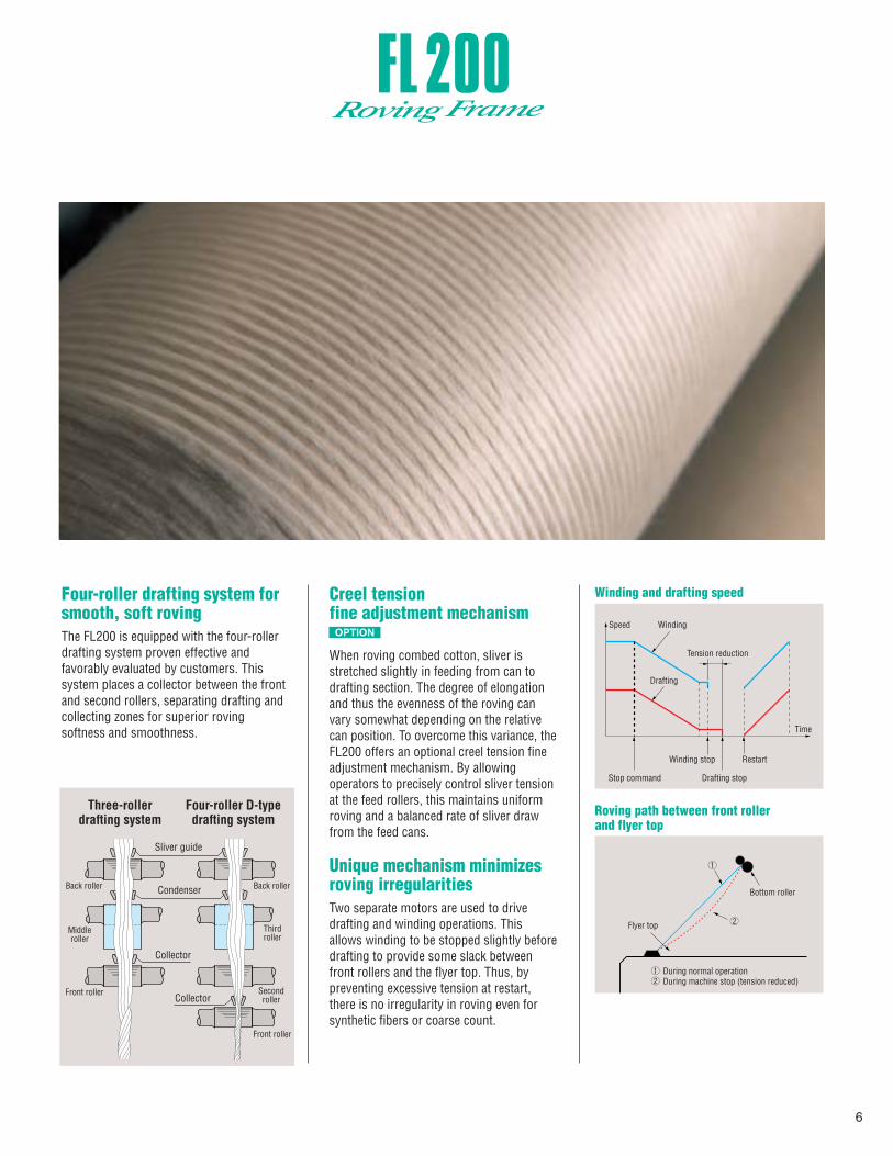
Winding and drafting speed
Roving path between front rollerand flyer top
Flyer top
Bottom roller
During normal operationDuring machine stop (tension reduced)
WindingSpeed
Drafting
Tension reduction
Time
Restart
Drafting stop
Winding stop
Stop command
Four-roller drafting system for smooth, soft rovingThe FL200 is equipped with the four-roller drafting system proven effective and favorably evaluated by customers. This system places a collector between the front and second rollers, separating drafting and collecting zones for superior roving softness and smoothness.
Creel tension fine adjustment mechanism
When roving combed cotton, sliver is stretched slightly in feeding from can to drafting section. The degree of elongation and thus the evenness of the roving can vary somewhat depending on the relative can position. To overcome this variance, the FL200 offers an optional creel tension fine adjustment mechanism. By allowing operators to precisely control sliver tension at the feed rollers, this maintains uniform roving and a balanced rate of sliver draw from the feed cans.
Unique mechanism minimizes roving irregularitiesTwo separate motors are used to drive drafting and winding operations. This allows winding to be stopped slightly before drafting to provide some slack between front rollers and the flyer top. Thus, by preventing excessive tension at restart, there is no irregularity in roving even for synthetic fibers or coarse count.
OPTION
Three-rollerdrafting system
Four-roller D-typedrafting system
Sliver guide
Condenser
Collector
Collector
Back roller Back roller
Middleroller
Front roller
Front roller
Thirdroller
Secondroller
6

Simple Operation, High Reliability, and Easy Maintainability
Function panel Setting functions • Spinning conditions • Roving bobbin formation• Flyer speed control (automatic optimum pattern calculation,
speed control pattern graph display)• Stop sequence operation, etc.
Monitoring functions• Production volume (shift counter) • Transition of efficiency for each shift • History of running conditions for the last 24 hours • Flyer speed, delivery speed, twists, and time to full bobbin• Inverter/servo amplifier monitor • Troubleshooting, history
Management functions• Setting condition memory function • Memory card• Maintenance schedule management function
Large color function panelA 10.4-inch, 2-language color function panel equipped with a Web browser improves interface ability. Connection to an internal or external network is possible for exchange of information or data, thereby expanding the capability of today’s spinning mills.
TMS (Toyota Monitoring System)Advanced mill management has never been easier. TMS, Toyota’s original monitoring software, allows you to effectively conduct mill management—including maintenance—right from your office. Simply use a LAN cable to connect multiple Toyota machines to any commercially available PC in the office. That PC can then be used to easily access various kinds of information, such as shift reports, and to directly view the function panels of all connected machines for an accurate assessment of how the machines are operating. What’s more, machine setting data can be transferred to another machine without using memory cards—a great way to save time and effort when changing yarn types.
Color LCD touch-screen function panel simplifies input and monitoring
Running condition monitor Shift report Troubleshooting
OPTION
7

Energy-saving Clearer Waste Collector (CWC) prevents fly accumulation (pneuma-less type)The CWC deposits bottom clearer fly into the waste trough, where a conveyor belt carries it to the waste container at the out end. The pneuma-less suction mechanism uses far less electricity and simplifies maintenance. The elimination of pneumatic noise and microscopic dust improves factory environment.
Bobbin collision prevention functionIn conventional roving frames, an empty bobbin can occasionally be erroneously set at an angle and can thrust the spindle upwards after doffing, leading to damaged components. The FL200 employs an overload detection function on the servo motors used to raise and lower the bobbin rail to automatically sense this bobbin insertion fault and immediately stop lifting of the bobbin rail. This new mechanism prevents these kinds of accidents from happening.
Automatic roving-endpositioning device for easyrestartingThe need for manual procedures is further reduced through automatic roving-end attachment. When the bobbin rail is raised to the restart position after doffing and new bobbin insertion, the machine restarts in reverse at low speed for a certain period and then switches to normal rotation. Roving ends are automatically positioned and pressed tightly against the bobbins to begin winding.
High-twist roving cutting function An extra twist is applied locally prior to lowering the full bobbin in order to protect the area where the roving is easily cut. This enables the roving to be cut properly between the presser and the wound bobbin regardless of the type of fiber, enabling automatic doffing.
Synchronized back-up system for power failureA back-up power system in the FL200 protects against all kinds of power supply fluctuations, including power failures, enabling the machine to stop while maintaining the synchronization between the spindles and the drafting rollers. In addition, the amount of time back-up power is provided during momentary interruptions to ensure continuous operation has been significantly increased.
Stop motion upon roving breakageA breakage in the middle of the package during operation may cause stray cotton fiber ends to become wound onto adjacentbobbins, causing chain breaks and affecting quality. To prevent this, a phototube with a special circuit detects breakage and immediately stops the machine.
Flyer rail covercleaning device
(option)
CWC
Roving ends are smoothly wound onto the bobbin
Scraper
Belt
Belt
Waste trough
Scraper
8
Bobbin rail lowers(roving is cut between presser
and bobbin)
Machine stop motion
Flyers and bobbins rotate at thesame speed without delivery
(extra twist applied)
Normal roving resumes,feeding extra twist section inside flyer
Doffing

Operation Sequence
Floor Plan
Forks move forward
Before doffing
Forks grasp full bobbins Forks simultaneously graspfull and empty bobbins
Setting of emptybobbins is completed
Empty bobbins are inserted
Preparing to raise full bobbins
Full bobbins are transfered to the ring spinning frame
The shortest doffing machine stoppage time in the world 3.5 min.3.5
Carrie rail& rack
Safety door
ABCD
508 (20)
4,465400
1,0501,000
508 (20)
4,065400
1,050600
Can diameter
Dimensions
Model FL200 (520 mm staff)
12010896
15,74014,18012,620
L
16,95515,39513,835
Numberof spindles
Dimensions(frame length)
75.5
115
L1100
Min. 3600
3245
2000
600 1360
600
965 B C D C
AE*
1360
Carrier frame Hanger rail Lifter pillar
ForkTransfer rail
Control box for FRD
Hanger arm
Carrier
Lifter
*440 mm staff only
FRD Stationary Doffer for Roving FramesToyota’s FRD stationary doffer for roving frames has forks that simultaneously hang on the full bobbins and empty bobbins, thus dramatically reducing the stoppage time required during doffing. Downtime is 3.5 minutes, the shortest in the world. Because it’s simply designed and independent of the roving frame, maintenance is easy. Toyota guarantees that the FRD will give stable doffing.
9

2–3
F–2
15–20–25
OH534-110
20–25–30
Cradle type
Drafting system
Weightingarm
Texparts
4-roller (D type)
40–51 mm
4-roller (D type)
Texparts
51–76 mm
3-roller
Texparts
44–76 mm*
3-roller
Texparts
22–40 mm
Maker
Type
Positive intermittent revolving clearer with comb
F
9–12–15
10–15–202
3
B
F
15–20–25
10–15–20
10–15–20
OH514-110
15–20–25
9–12–15
10–15–20
10–15–20
OH534-110
20–25–30
10–15–20
15–20–25
OH524-110
Weight (kg/2 spindles)
Cradle radiusx width (mm) 34.5 x 40 45.0 x 40 58.0 x 40 45.0 x 40
2
B
3
Bottomroller
diameter(mm)
28.5 (knurled)
28.5
28.5
28.5
28.5 (knurled)
28.5
31.75
31.75
31.75
31.75
28.5
28.5
28 35 3528
10.4-inch color function panel, bobbin misplacement prevention device, automatic grease lubrication for draft gearing,automatic grease supply system for flyer gear, clearer waste collector (pneuma-less type)
Creel
Power required
High speed
Options
3–B
Clearer
Specialdevices
(included)
High speed
Quality
45–
Up to 508 mm (20") diameter x 1,150 mm (45") high
Main motor: 15kW
Automatic roving-end positioning for machine restart, high-twist roving cutting device
Bobbin jumping prevention device
Quality
Positive revolving feed roller with extended creel (single sliver feed system)
Feeding can
Automatic flyer speed control with inverter
Creel tension fine adjustment mechanism
Flyer-rail cover cleaning device, automatic travelling suction cleaner, TMS
PK1500-02
PK1500-02
PK1500-001938
PK1500-001938
28.5 (knurled)28.5 (knurled)
* Cradles for 51 to 76 mm length fiber must be ordered separately.
Roller gauge(mm)
Top rollerdiameter (mm)
Staple length
Main Specifications (Unit: mm)
Design and specifications are subject to change without prior notice.
(Unit: mm)
Automatic tension controller, roving irregularity prevention, roving stop at set length/position,package shoulder collapse prevention, optical electronic roving stop motion, optical electronic sliver stop motion,
stop motion upon roving breakage at middle part of package Toyota originalHigh Speed Flyer
Operation andmaintenance
Operation andmaintenance
Automation
Max.193(total)4–7
35–
49–
Max.193(total)60–
42– Max.185(total)57–
73– Max.185(total)52–
62–
1,360 1,300
115
L
1,300 1,380
1,100232.5
265
965 2,
000
300
100 50
965B
A
C D C
60
1,380 1,320115
L
1,320 1,400
1,100
233.5
265
60
965
2,00
030
0
100 50
965
B A
C D E
Power source
Power source
Floor Plan
Model FL200 (440 mm staff)
144
108 96
15,980
12,02010,700
17,195
13,235
132 14,660 15,875
120 13,340 14,555
11,915
AB
C
Dimensions
4,805 400 990
508 (20)
D
E1,0001,450
4,405 400 990
508 (20)
6001,450
DimensionsNumber of spindles L (frame length)
Can diameter
Configuration 5-row staggered
140
108
96
DimensionsNumber of spindles
18,340
14,180
12,620
19,555
120 15,740 16,955
15,395
13,835
Can diameterDimensions
4,465
400
1,050
508 (20)
1,000
4,065
400
1,050
508 (20)
600
L (frame length)
Model FL200 (520 mm staff)
10
A
B
C
D

Printed in Japan
Textile Machinery Division2-1, Toyoda-cho, Kariya-shi, Aichi 448-8671, JapanURL: http://www.toyota-industries.com/textile/
Sales Department Tel: 81-566-27-5320 Fax: 81-566-27-5301
Service DepartmentTel: 81-566-27-5325 Fax: 81-566-27-5681
G L O B A L S E R V I C E N E T W O R K
1. Korea 2. China (Shanghai, Shaoxing, Wujiang, Jinan, Changzhou) 3. Taiwan 4. Thailand 5. Indonesia 6. India 7. Pakistan 8. Turkey9. Europe (Italy, France, Switzerland) 10. U.S.A. 11. Brazil
71
6
5
810
11
4
23
9
Global service centers
1. Plant layout Before the delivery of machinery, Toyota proposes an installation layout which is designed to optimally suit a customer’s plant.
2. InstallationA Toyota expert supervises installation and instructs customers on machine operation.
3. Customer support service A variety of customer support services are provided, such as supplying spare parts to ensure continuous and smooth operation.
4. TrainingToyota provides a wide range of courses from handling Toyota machinery to management. These substantial courses help customers obtain a level of expertise in both the mechanical knowledge and efficient usage of machinery.
5. Service networkWith service centers located around the world, Toyota is able to quickly respond to the needs of local customers.
Total worldwide customer service
Toyota offers a full range of services, from plant layout consulting to machinery installation and after-sales service. The Toyota Textile Machinery Training Center provides a variety of training courses which precisely match the needs and abilities of individual customers. Toyota also helps train customers’ technical engineers from around the world.
Design and specifications are current as of March 2007.Reproduction in whole or in part without written permission is prohibited.©All rights reserved. 01.2008This brochure is printed on recycled paper with soy ink.


![[3.5 Monster Class] Roving Mauler](https://img.pdfslide.us/doc/110x75/55cf9a9d550346d033a2973a/35-monster-class-roving-mauler.jpg)