Embed Size (px)
Citation preview

Scholars' Mine Scholars' Mine
Masters Theses Student Theses and Dissertations
1966
The construction of a Fermi neutron chopper for cross section The construction of a Fermi neutron chopper for cross section
measurements measurements
Cleon Marion Mobley
Follow this and additional works at: https://scholarsmine.mst.edu/masters_theses
Part of the Nuclear Engineering Commons
Department: Department:
Recommended Citation Recommended Citation Mobley, Cleon Marion, "The construction of a Fermi neutron chopper for cross section measurements" (1966). Masters Theses. 5788. https://scholarsmine.mst.edu/masters_theses/5788
This thesis is brought to you by Scholars' Mine, a service of the Missouri S&T Library and Learning Resources. This work is protected by U. S. Copyright Law. Unauthorized use including reproduction for redistribution requires the permission of the copyright holder. For more information, please contact [email protected].

THE CONSTRUCTION OF A FERMI NEUTRON
CHOPPER FOR CROSS SECTION
MEASUREMENTS
by
CLEON MARION MOBLEY, JR . - 1 q.-t~ -
A
THESIS
Submitted to The Faculty of
THE UNIVERSITY OF MISSOURI AT ROLLA
1n partial fulfillment of the requirements for the
Degree of
MASTER OF SCIENCE IN NUCLEAR ENGINEERING
Rolla , Missouri
1966
Approved by
~~e~ (Advisor )
G.~%~M

ll
ABSTRACT
A Fermi neutron chopper and control system has been
constructed and put into operation at the end of the UMR
Reactor thermal column.
The operation of the chopper has been demonstrated
by reproducing the slow neutron cross section data for
aluminum and by measuring the previously undetermined
slow cross section of cobalt.
The chopper which is powered by a serles DC motor
consists of 34 cadmium plated stainless steel blades
separated by l/16 inch aluminum spacers. The design
incorporates the better characteristics of the Brook-
haven and Argonne slow choppers. Speed regulation is
accomplished using a silicon controlled rectifier feed
back system which permits speeds from 50 to 15,000 rpm.
The speed variation at all speeds is less than one percent.
Aluminum cross sections in an energy range from
0.006 to 0.08 eV were shown to duplicate the Argonne
results except for one additional peak which appeared
at about 0.02 eV. Additional investigation is planned
to explain this peak.
Cobalt cross sections were determined as a function
of energy from 0.005 to 0.1 eV. These data are believed
to be the first published for cobalt in this energy range.

iii
ACKNOWLEDGEMENTS
The author is grateful to the Atomic Energy Commis
sion for financial support and to many people on the UMR
campus for their technical assistance throughout this
project.
In particular, the author wishes to thank Dr. Doyle
R. Edwards, Director of the Reactor Facility, for his
advice and assistance throughout all phases of this work.
He is also grateful to Professor George McPherson
of the Electrical Engineering Department for his help in
designing the speed control mechanism and to Mr. Alva
Elliott, Reactor Supervisor, for assistance with the
electronics.
A special word of thanks is due to Mr. Lee Anderson,
Machine Shop Supervisor, for his high quality work and
his helpful advice.
lV
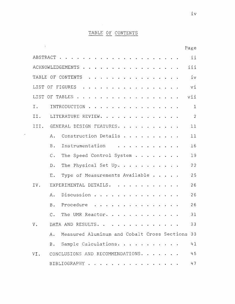
TABLE OF CONTENTS
Page
ABSTRACT . . . . . . . . . . . . . . ll
ACKNOWLEDGEMENTS . . . . . . . lll
TABLE OF CONTENTS . . . . . . . . . . . . lV
LIST OF FIGURES . . . . . . . . . . . . Vl
LIST OF TABLES . . . . . . Vll
I. INTRODUCTION . . . . . 1
II. LITERATURE REVIEW. . . 2
III. GENERAL DESIGN FEATURES. . . . . ll
A. Construction Details . . . . ll
B. Instrumentation . . . . . . . 16
c. The Speed Control System . . . . 19
D. The Physical Set Up. . . . . 22
E. Type of Measurements Available . . . . 25
IV. EXPERIMENTAL DETAILS. . . . . . . 26
A. Discussion . . . . . . 26
B. Procedure . . . . . . . . 26
c. The UMR Reactor. . . . . . 31
v. DATA AND RESULTS. . . . . . . . . 33
A. Measured Aluminum and Cobalt Cross Sections 33
B. Sample Calculations. . . . . . . 41
VI. CONCLUSIONS AND RECOMMENDATIONS. . . 45
BIBLIOGRAPHY . . . . . . . . . . 47
v
Page
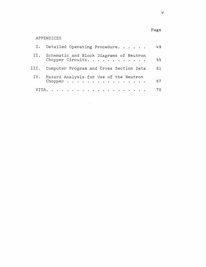
APPENDICES
I. Detailed Operating Procedure .. 49
II. Schematic and Block Diagrams of Neutron Chopper Circuits. . . . . . . . . . . . 55
III. Computer Program and Cross Section Data 61
IV. Hazard Analysis for Use of the Neutron Chopper . . . . . . . . . . . . . . 6 7
VITA. . . . 70

LIST OF FIGURES
Figure
l Neutron Chopper Rotor with Cover Removed
2 Neutron Chopper Rotor and Cover
3 Rotary Shutter in Open Position
4 Neutron Chopper Assembly
5 Neutron Detector and Pre-Amplifier
6 Reactor Thermal Column and Collimators
7 The Experimental Floor
8 The Neutron-Energy Distribution
9 Neutron Chopper Control Panel
10 Slow Neutron Cross Sections of Aluminum
ll Slow Neutron Cross Sections of Cobalt
12 Wiring Diagram of Complete System
13 Connection Diagram for Multi-Channel Analyzer
14 Schematic Diagram of The Speed Controller
15 Schematic Diagram of Tachometer
16 Schematic Diagram of BF 3 Pre-Amplifier
Vl
Page
12
15
17
18
20
23
24
29
30
37
40
56
57
58
59
60

vii
LIST OF TABLES
Table Page
I Measured Aluminum Cross Sections 35
II Measured Cobalt Cross Sections 38
III List of Apparatus 54
IV Computer Program to Calculate Cross Sections 62
V Input Data for Cobalt Cross Sections 63
VI Computer Output Data for Cobalt Cross Sections 65

1
I. INTRODUCTION
The major purpose of this thesis is the design and
construction of a Fermi (slow) neutron chopper using modern
detection methods. Therefore, a significant portion of
this paper is allotted for the purpose of describing the
chopper, its instrumentation, and its experimental signifi
cance. A secondary purpose for this work is to demonstrate
the usefulness of the neutron chopper by measuring a pre
viously undetermined neutron cross section.
This work includes the measured cross sections of
cobalt as a function of energy from 0.005 eV to 0.1 eV.
This is a significant energy range in the construction of
low temperature thermal reactors because the most probable
thermal neutron at 20°C corresponds to 0.025 eV. A litera
ture survey revealed that the total cross section of cobalt
had not been reported for the low energy range from 0.005
to 0.03 eV.
Aluminum cross sections were also measured as a means
of standardizing the energy determination by making reference
to the known peaks in the aluminum cross section.

2
II. LITERATURE REVIEW
Neutron choppers can be separated into at least two
distinct groups, fast choppers and slow choppers. Fast
choppers are designed for the purpose of pulsing a beam
of high energy neutrons above the cadmium cutuff region
while the latter is designed for pulsing (or velocity
selection purposes) in the thermal neutron region. The
high neutron flux available in reactors opens the possibility
of high resolution measurements of neutron velocities by
timing the neutrons electronically as they move over a
particular length of path. These time of flight methods
of velocity selection were developed (1,2) principally
ln connection with pulsed cyclotron neutron sources.
However, the techniques involved have been employed di
rectly for use with neutrons produced by reactors (3).
In the time of flight method, a burst of neutrons on the
order of several microseconds duration is produced and
the time required for the neutron to reach the detector
some distance away is measured electronically (4).
The general principles involved in the velocity selec
tion are the same whether the bursts are produced by a
modulated cyclotron or a neutron chopper operating on a
reactor. The following simple relations hold for the
energy, velocity, and the time of flight over a one meter
path. The velocity of a particular neutron over a one
meter path length is given by (4)

The energy ln electron volts is given by
E = 51.5 X l0 2 /t2
t = 71.5/lr-
Where:
t = time in micro-seconds
E = energy in eV
V = Velocity in m/sec
The resolution in velocity and energy is given by
6V = -loG 6t = - lo-6v2 6t t2
3/2 = - ·028 E
3
The shape of the neutron burst function and that of
the counter huvebeen handled differently by several sources
(3,4,5). Indeed this shape would vary with the type and
design of the chopper and with its detection equipment.
It is generally agreed, however, that the actual shape
can be replaced by an equivalent triangle ln order to
simplify calculations (23). The chopper can not produce
a pure knife edge effect because of its physical size.
Therefore, there is always some departure from the ideal
square pulse.
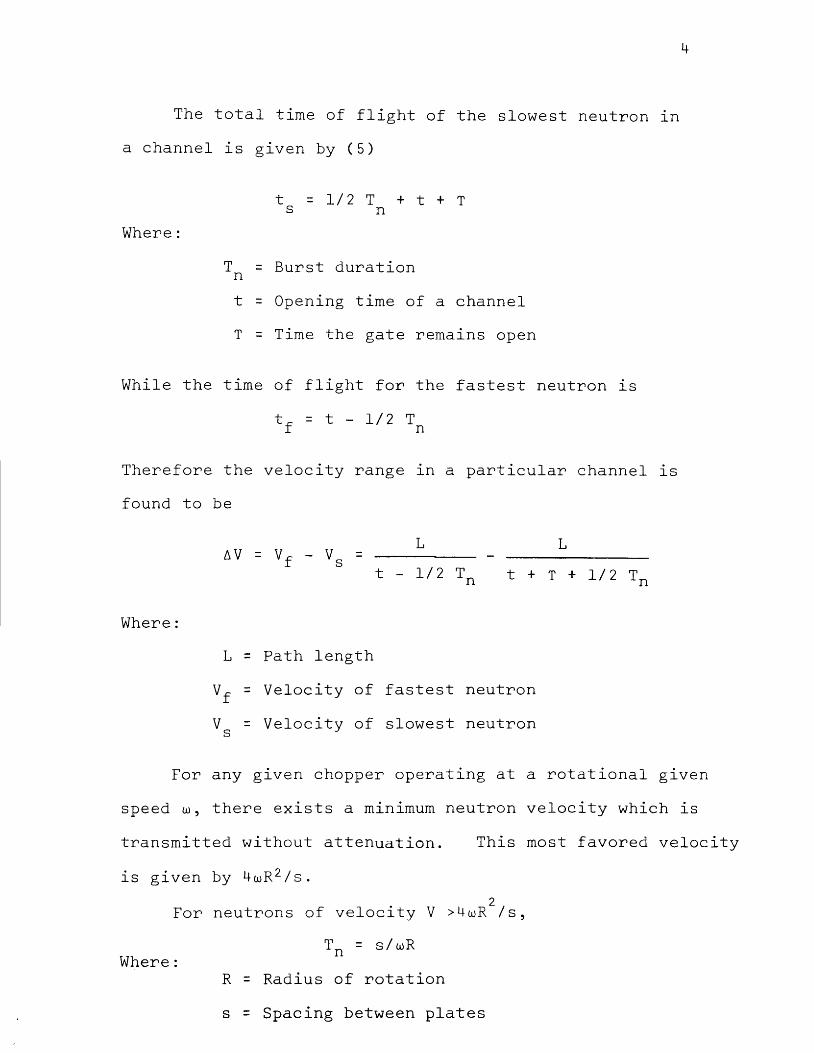
The total time of flight of the slowest neutron ln
a channel is given by (5)
Where:
t = 1/2 T + t + T s n
T = Burst duration n
t = Opening time of a channel
T = Time the gate remains open
While the time of flight for the fastest neutron lS
Therefore the velocity range ln a particular channel lS
found to be
L L
t - l/2 Tn t + T + l/2 Tn
Where:
L = Path length
Vf = Velocity of fastest neutron
V = Velocity of slowest neutron s
4
For any given chopper operating at a rotational g1ven
speed w, there exists a minimum neutron velocity which is
transmitted without attenuation. This most favored velocity
2 For neutrons of velocity V >4wR /s,
Where: Tn = s/wR
R = Radius of rotation
s = Spacing between plates
5
But when V lS less than this most favored velocity,
Tn = 4 ls/wV - 4 R/V
The Fermi Chopper lS designed primarily for the produc
tion of neutron bursts while the actual velocity selection
is performed by an electronic timing (4). Electronic tim
ing has been accomplished (4) by a series of photo cells
activated by a rotating beam of light which actuates several
counters as a function of time. Later innovations have
made use of the multichannel analyser operating in the
time mode (5).
Other types of choppers called velocity selectors
have been developed by Dunning et al (6), by Ringo (7),
and Wollan (8). The purpose of the velocity selector is
not only to pulse the beam of neutrons but also to act
as a mechanical monochromator to select a narrow band of
neutron energies while rejecting all others.
A mechanical monochromator selects the narrow band
of velocities with no time of flight measurements involved.
Monochromators have certain advantages over a time of flight
instrument. For example, activation with mono-energetic
neutrons can be accomplished with the monochromator and
is impossible with the time of flight method (9). The
monochromator is at a disadvantage concerning cross section
measurements in that only one velocity can be studied at a
time (4). When used on a low power reactor, choppers are
desired over monochromators because of the higher count
rate possible (10).

6
This paper concerns the techniques used in the slow
chopper where little or no monochromatization of neutrons
results. The energy measurement is performed by electronics
on a time of flight basis. The Brookhaven slow chopper
(11), designed to contain curved channels, produces some
energy selection of neutron bursts. However, the major
purpose for the curved plates is to facilitate more ef
ficient transfer of neutrons through the chopper. A slow
chopper was used by Fermi at Argonne in 1943 (4), and
later his design was incorporated by Brille and
Lichtenberger (12) at Argonne. A similar chopper lS in
use at the Harwell, England Pile (13). The Argonne chopper
(using the Fermi design) is made up of alternate layers
of cadmium and aluminum sheets driven by an electric motor
at speeds up to 180 revolutions per second (2). Crystal
filtered neutrons (8) and lead-filtered neutrons (15)
have been used for the purpose of velocity selection.
The effect of higher order reflections is negligible in
the epithermal region where the crystal monochromator lS
principally used but is a serious drawback in the use of
thermal neutrons. As a result the mechanical velocity
selector is preferdble for thermal neutron work. Indeed
some work has bee~ done using combinations of a crystal
filter and a neutron chopper (14).

7
One of the principal uses of a neutron cho~per is
1n determining total neutron cross sections (16,17).
There are three basic techniques for measuring cross sec
tions: Beam transmission, in pile, and activation (10).
In the beam method a beam of neutrons is taken out of
the reactor by a thermal column or a beam tube. The
neutrons are made to pass through the specimen and the
intensity is recorded with or without the specimen. The
neutron chopper can be used with the beam method to deter
mlne cross section as a function of energy. In the pile
method the material is placed ln the core and the change
in reactivity is measured; in this method only the absorp
tion cross section can be determined. The activation
method consists of irradiating a specimen a given time
and observing its induced activity. However, because
all the absorptions do not produce activity, only the
activation cross section is measured.
This work will demonstrate a method for total cross
section measurement using the beam transmission method
and a neutron chopper. Total cross section can be dis
tinguished from the scattering and absorption cross sec
tions by the counter used (10). A single BF 3 counter
tube subtending only a small angle from the specimen would
indicate the total cross section while a four pi counter
would detect the scattered neutrons and therefore indicate
only the absorption cross section.

8
Total cross section measurements have been achieved
through the use of a slow neutron chopper by several
investigators (12, 16, 17). The general procedure is
to measure the thermal neutron spectrum with the sample
1n the neutron beam and then to compare this to the
thermal neutron spectrum without the sample. Schunk,
Randolph and Brugger (18) determined the total cross
section of Ti, V, Y, Ta, W, using a slow chopper operat-
ing at a speed of 2,100 rpm. A 1024 multichannel time
analyser was used as the time energy base. Stone and
Slovacek (19) determined the cross sections in the range
above the cadmium cutoff using the 2 inch shutter composed
of l/16th inch borated phenoic plates and l/16th inch
aluminum spacers. Cadmium cannot be used as a shutter
blade in this region because of its transmission of
epithermal neutrons.
The familiar equation (20,21,22) I
derived as follows:
-Nat = I e 0
lS
The change in neutron intensity of the pass1ng through
thickness dt is
di = - aiNdt
I
J~I =
Io 0

or,
Where
a =
N =
t =
Io =
I =
I IO
a
The
-aNt = e
= - ln I/Io Nt
total microscopic cross section
Number of atoms per cm 3
Thickness
The count rate without the sample in
The neutron count rate as a function energy with the sample in the beam
9
the beam
of
A discrete cross section is then calculated for each
energy increment as a function of the time of flight.
Hoag (23) describes a classical method for determining
total neutron cross section. In this method the log of
the transmitted intensity is plotted as a function of the
material thickness and the slope of this graph is taken
to be the total average cross section.
This method is advantageous because of its simplicity
but is limited in that only the average cross section for
the energy of the neutrons in the beam can be determined.
Total cross sections may be determined by using a crystal
spectrometer (24,25). However, the crystal spectrometer
has a limited useful energy range of 0 .l to 10 eV because
10
of the loss of intensity on the low end and loss of resolu-
tion at higher energies (23). Neutron choppers have the
advantage of high energy resolution while still maintaining
a relatively high count rate. A slow chopper developed
by Fermi as early as 1943,to determine total cross sec-
tions at various energies, was later improved by Brill
and Lichtenberger (12). The advantage of this type of chop-
per is the possibility of high energy resolution in the
fractional eV range. The Brookhaven chopper using curved
blades and wide spacing between the blades (27) was de-
signed to improve the energy resolution in the extreme
low fractional eV level. This chopper is capable of
measurements of the slow neutron spectrum extending to c
a wave length of 25A(4).

11
III. GENERAL DESIGN FEATURES
The Brookhaven slow chopper (30) was used as a model
ln designing the present chopper. Many changes were neces
sary for reasons of compatibility with the UMR Reactor,
financial resources, and experimental purpose. The design
of the gear box and the light beam mechanism which it con
trols are identical to the Brookhaven design.
A. Construction Details
This design differs from many choppers(5,23) in that
spacing between the blades is accomplished by very narrow
strips of aluminum providing a space consisting of about
60% air, while other choppers use solid aluminum as the
spacer between the plates. While the aluminum itself has
a low cross section it is believed that air spacing is
better because of less neutron scattering. Egelstaff (27)
estimates that removing 87% of the aluminum reduces the
scattering to 10%.
The rotating chopper (Fig. 1) has 34 blades, 3 1/2
x 4 3/4 x 0.16 inches thick which have been cadmium plated
to a thickness of .002 inches each side. Sets of five
aluminum strips 3 1/2 x 3/8 x l/16th inch are used as
spacers between the blades. This sandwich type structure
is held together by 15 steel bolts.

Fig.l
CADMIUM PLATED STAINLESS STEEL
BLADE SHAFER
Neutron Chopper Rotor With Cover Removed
ALUMINUM SPACER
I I

The chopper is of the same general design as the
Brookhaven chopper except for the following changes:
13
The rotor is designed so that the blades can be operated
in the curved position as used at Brookhaven or as a con
ventional flat Fermi chopper. This is accomplished by
removing the shaper (Fig. 1) and replacing it with a
curved form. When this change is made it will be neces
sary to rebalance the rotor if rotational speeds in excess
of 4,000 rpm are to be encountered. A boron-polyethylene
mixture (Poly-B) supplied by Reactor Experiments, Inc.
is used as a fast neutron shield rather than the conven
tional polyester-boron mixture. This change was made
because Poly-B was commercially available. This boron
mixture is placed on the ends of the chopper (See Fig. 1)
to act as a shield for high energy neutrons which would
penetrate the cadmium plate and thus increase the epl
cadmium background.
Cadmium is a soft metal which deforms easily under
the forces of high rotational speeds. Stainless steel
cadmium plated blades. are considered superior to pure
cadmium because of the increase in strength which is neces
sary at high operating speeds. This practice also permits
small discontinuous spacers to be used between the blades
rather than solid sheets of aluminum which would other
Wlse be necessary for strength. The spacing between cad
mlum blades is wider than most choppers (5,23) which allows
14
a wider neutron window and thus, ln the interest of resolu
tion, requires an increase in rotational speed. This com
bination is possible because of the high strength materials
which have been used in the construction. Strength in
materials limits the top speed to about 500 m/sec (27).
This particular rotor which is believed to be safe up to
15,000 rpm is covered with a l/8 inch aluminum sleeve to
reduce windage friction (See Fig. 2).
A second rotor, (now under construction) which uses
five curved blades with a spacing of l/2 inch, is designed
to increase the intensity of the extreme low energy neutrons.
The curved blades have a radius which varles between 5 and
7 inches and are designed to function as a Fermi chopper
and act as a crude velocity selector as well. This curved
blade chopper operates at a disadvantage because only one
burst of neutrons can be used per revolution. However,
this is sometimes considered as an advantage particularly
in the case of the extremely low velocity neutrons because
the duty cycle of the chopper requires a long waiting
period after the initial burst (4).
The two rotors described above are designed to be
interchangeable for use with the motor and the timing
mechanism. The driving motor manufactured by General
Electric is rated 1/3 horsepower at 12,000 rpm, with a
no load speed of 16,000 rpm. However, because of fric
tion in the recently purchased chopper bearings, a top

r ALUMINUM COVER
Fig.2 Neutron Chopper Rotor and Cover

16
speed of 10,000 rpm is realized. This top speed will
probably increase as the bearings become worn. For speeds
1n excess of 10,000 rpm a Sears, Roebuck ar1d Co. router moto1
rated 3/4 horsepower at 23,000 rpm is substituted directly,
requiring no change in the electrical controls.
B. Instrumentation
Neutron time of flight measurements are accomplished
using a RIDL model 34-12B multichannel analyzer which is
controlled by a photocell actuated by a collimated beam
of light reflected from a mirror on the shaft of the rotor.
(See Figs. 3,4). This angle of reflection is a function
of the position of the chopper blades and is controlled
by mov1ng the position of the light source. This light
source is positioned by a gear box achieving a reduction
of 80 to 1 in combination with provisions for angle indica
tion from 0 to 16 degrees. The gear box is designed such
that the smallest division on the adjustment knob is equlva
lent to 0.5 minutes (See Fig. 4). The spacing between
channels is accomplished by a RIDL Model 54-6 time base
generator which can control channel widths as small as
12.5 microseconds. The time base generator begins its
sequence upon receiving a 5 to 10 volt pulse from the
photocell. This process is repeated until adequate
statistics are accumulated. The count in the analyzer
memory therefore represents an inverse energy plot with

Photo Cell
Neutron Beam
Cadmium Collimator
Fig. 3
Light Source
Parallel Light
Timing Angle-9
Cadmium Plated Stainless Steel
Mirror
2M Flight Path
Rotary Shutter In Open Position
Detector
0
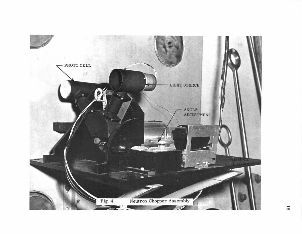
PHOTO CELL
,___ LIGHT SOURCE
....... 00

19
the highest energy neutrons appearing ln the first channel.
A Reuter-Stokes BF 3 proportional counter is used as the
neutron time of flight detector. The output of the tube
is connected to a pre-amplifier similar to the Minneapolis
Honeywell 1906-Hl (See Fig. 5) whose output is connected
to a multichannel analyzer some forty feet away. High
voltage is provided by a Tracerlab SC-86 power supply cap
able of voltages up to 2,500 volts (See Fig. 5). A neutron
catcher made of paraffin and boron is located immediately
behind the BF 3 counter in order to absorb the remalnlng
neutrons. A model 515A Textronix oscilloscope is used
as a general service instrument and particularly to insure
that the control pulses have the proper rise time and
are free of oscillations and transients that would produce
counting or control errors.
C. The Speed Control System
The most desirable chopper would involve a system
allowing continuously variable speed which is precisely
regulated at any setting. Egelstaff (26) describes a sys
tem in which a precision audio oscillator operates a syn
chronous motor. Since the construction of such a system
is economically prohibitive for such a project, a compromlse
system is designed. A simple synchronous motor would
provide constant operation at 3,600 rpm. This speed could
then be varied by changing gear ratios. The North Carolina
State University chopper (27) is designed on this principle.

BF3 DETECTOR

21
This system permits constant speed operation but the speed
must be varied in discrete steps. Also, the thought of
belts or gears operating at 15,000 rpm is discouraging.
Another possibility is an ordinary DC motor coupled directly
to the chopper shaft with a manual speed control. This
system is selective but lacks the desired stability that
might be achieved through the use of a synchronous system.
The system described herein is a compromise between
speed control and regulation: This system employs a
manually controlled series motor directly coupled to the
chopper using a negative feedback loop to regulate the
speed of the otherwise unstable motor. Using this system,
the speed can be controlled as with an ordinary DC motor
while enjoying some degree of regulation approaching but
not equivalent to an AC motor.
Control of the motor speed 1s accomplished by a silicon
controlled rectifier which obtains its feedback signal dur
ing the preconduction time. The feedback is determined
by the back emf of the motor during the non-conduction
cycle of the diode. (See schematic diagram in Appendix II).
Rotational speed is indicated by a multi-vibrator tachometer
which is operated from the photocell. This measurement
allows the operator to bring the chopper up to an approxi
mate speed which is indicated directly on the tachometer.
A scaler deriving its signal from the photocell is provided
for a more precise speed determination. The operator may
thus use the scaler to calibrate the tachometer at any
particular speed.
22
For ordinary work (i.e., spectrum measurement), the
speed regulation inherent in the feedback circuit of the
control mechanism is sufficient. However, for more precise
work, the input power to the control mechanism should be
regulated.
D. The Physical Set ~
The entire chopper assembly lS mounted on the thermal
column door directly in front of the thermal column. A
neutron collimator made of wood approximately seven feet
long (Fig. 6) is designed to replace one of the graphite
stringers in the thermal column and extend approximately
three feet inside the thermal column door. This collimator
defines a neutron beam 1-1/2 by 3 inches. A baffle made
of cadmium located about two feet inside the thermal column
door and attached to the end of the collimator is provided
to absorb any remaining neutrons. The neutron beam is
again confined immediately after leaving the door and before
entering the chopper. Neutron and g&mma shutters are pro
vided to control the beam.
After leaving the rotor, the neutrons travel over a
flight path of 2.00 m where they are detected by a BF 3
counter. (Figs. 6,7).

Pool
Reactor Core
r-4ft Graphite
Poly-B
Concrete-Steel Door
Top View Cross Section
Motor
Chopper
2M Neutron Flight Path
Fig. 6 Reactor Thermal Column and Collimators
"A" Neutron Absorber
Poly-B 6 inx 4 inx 2 in each Cadmium 0.060in Boral 0.25in Lead 0. 50 in
BF3 Detector


25
E. Type of Measurements Available
Valente, Hoag, and others (29, 23,26) describe several
experiments which are performed by a pulse neutron source.
Several of these experiments are possible using the UMR
facility: Neutron flux-energy distributions for a given
thickness in the graphite thermal column can be determined.
From these data, total cross sections can be calculated.
Through the use of a four-pi counting system, absorption
cross sections can be measured. Several other experiments
may be possible with some additional equipment: i.e.,
measurements which lead to the decay constant (a) as a
function of the geometric buckling (B2). From the resulting
curve the diffusion coefficient (D) and the diffusion
length (L) may be calculated. Isenhour and Morrison (32)
describe a neutron capture gamma ray activation analysis
procedure which offers a number of reactions not available
to delayed gamma activation analysis. A neutron chopper
is the primary instrument used in this type work.

26
IV. EXPERIMENTAL DETAILS
A. Discussion
A beam of steady state neutrons corning from the reactor
is collimated into a l/2 by 3 inch column and allowed to pass
through a rotating shutter operating from 2000 to 10,000
rpms. These then separate bursts of neutrons are allowed
to travel over a fixed distance of 2 meters where they
are detected by a BF3
proportional counter. The faster
neutrons arrive at the counter ahead of the slower neutrons
thus providing the time of flight energy relationship.
At the instant the shutter is open a beam of light triggers
a photocell which triggers the multichannel analyzer (MCA) to
start counting neutrons at a preset time in rnicr~oseconds
per channel. If the rotating speed lS accurately known
as well as the geometry of the chopper itself and the
distance between the chopper and counter is measured, all
of the variables are known for calculating energy as a
function of channel number.
B. Procedure
The reactor lS brought up to power while the chopper
and the associated electronic equipment is allowed to
warm up. There is also some indication that the reactor
should be allowed to operate for at least 15 minutes at
constant power before the neutron count is started.

27
The speed of operation and the channel width are deter
mined by the energy range of the experiment and the desired
resolution. A high rotational speed will produce better
resolution but at the same time will decrease the time the
chopper is open which will result in the attenuation of
the low energy neutrons. The time the chopper remains open
(burst width) is given by (5)
Where:
T = s w R
S = Spacing between blades
w = Rotational speed (rad/sec)
R = Radius of rotation
The minimum velocity that is transmitted is therefore (5)
wR 2
v = m S
Therefore, the chopper must be operated at a speed great
enough to produce adequate resolution but slow enough to
permit the transmission of the desired low-energy neutrons.
For the aluminum cross sections, two runs were made
in order to check the accuracy of the data: A high-speed
run for good resolution at high energies and a low-speed
run for the low-energy neutrons. Rotational speeds of 2200
rpm and 6000 rpm were used for the low and high energy ranges
respectively.

28
It was observed that data taken near the minimum
velocity point (V ) tends to produce inconsistent results. m
This effect is probably due to the small variation in the
chopper speed which would thus cause the V to shift thus m
producing errors 1n the cross section near that point.
When a stable operating speed is reached, the spectrum
1s measured without any sample or absorber in the beam.
This determination gives the number of neutrons existing
in the beam as a function of energy (See Fig. 8). This
curve contains the thermal neutron spectrum plus the epi-
thermal neutrons which leaked through the cadmium blades
of the chopper. Because of this leakage a suitable back-
ground representing the leakage through the chopper must
be determined. A thin sheet of cadmium is placed in the
beam for this purpose while the analyzer is operated 1n
the subtract mode for a time equal to the previous run.
The sample whose cross section is to be measured 1s
placed in the beam behind the last collimator and the
spectrum is recorded. Finally, the cadmium and the sample
material are placed in the beam to determine the background
which is again subtracted. From the two resulting curves,
the cross section is calculated. Because the calculations
involved are tedious and repetitious, a suitable computer
program is designed for this purpose. The hand calculations
indicated in the next section demonstrate the procedure for
calculating the cross section for one point on the graph
(See Fig. 11). This calculation is repeated for as many

29
300
) ~ I
\
\ M-
I Fig. 8 0 ...-(
~ The Neutron-Energy Distribution -p:;
;::l 0
Neutron Chopper:w = 3100 rpm Tc = 25 microseconds, L =2M
::t: p:; 200 ~ ll. 00 z 0 p:; E.; ::;:J ~ z \
1\ \ ~ \
100
1\ ----- ~ ---
\
v ~ ~
1'-r-----r-- ,____
. 8 .165 .070 .039 .025 .017 .012 .0095 .0075 .0060 .0050 .0042 .0036 .0030
ENERGY (eV)

30
Fig. 9 Neutron Chopper ControlPanel

points as desired.
handle 99 points.
The computer program lS written to
Actually, the chopper lS incapable of
producing this much data at a particular single speed;
however, it is more convenient to process the data taken
from the multichannel analyzer if 9 9 channels are used.
The channels which contain poor statistics are then
discarded.
c. The UMR Reactor
The UMR Reactor ls a light water moderated and cooled
pool type reactor which is licensed to operate at a power
level of 10 kw. The reactor core contains 14 fuel elements
and 4 control elements which contain approximately 2788
grams of 90% U-235 enriched uranium oxide. The core is
suspended from a bridge which is moveable on tracks from
one end to the center of the pool. For this work, the
core lS moved to the extreme east end of the pool until
it rests against the graphite thermal column which pro
trudes into the pool. This produces the highest possible
neutron flux in the thermal column. A single 4" x 4" x 5'
graphite stringer is removed from the thermal column and
replaced by the collimator. This leaves about one foot
of graphite between the core and the collimator. Because
this distance is not adequate to produce a high thermal
to fast flux ratio, approximately one foot of moderator
lS added to the collimator. Hughes (4) suggests that
there is an optimum moderator thickness which will produce

32
the maxlmum thermal to fast flux ratio. This problem
should be investigated in order to improve the operation
of the chopper.
The present available power (lOkw) lS found to be
adequate but inconveniently low. Better results could be
obtained in less time if the now pending application to
lncrease the power level to 200 kw is approved.
33
V. DATA AND RESULTS
A. Measured Aluminum and Cobalt Cross Sections
These data and results include the measured micro
scopic cross section of aluminum and cobalt. The aluminum
cross section was used as a standard to check the opera
tion of the chopper and to provide a calibration point
for the pulse system. The cross sections given in the
Second Edition of BNL325 (31) are taken as the standard.
The results shown in Figure 10 include 4 points that
are inconsistent with the results obtained on the ANL
fast chopper. Several checks were made to check the
reliability of these points:
(1) The time base per channel and the rotational
speed was changed in order to eliminate the possibility
of channel error.
(2) The data was taken several times to disprove
the possibility of random error.
(3) The MCA was triggered by an external oscillator
with the chopper in the open position as a check on the
channel linearity.
Negative results were obtained in all cases. It is be
lieved therefore that these points do exist for the sample
measured. It is interesting to note that there lS a gap
in the ANL data near the points in question.

34
Very little data is available concern1ng cobalt slow
cross sections. Considerable work (31) has been done in
the energy range from .03 eV to 10 MeV but no data was
found in the region below .03 eV. This low energy reg1on
is of significant importance in thermal reactons because
the most probable thermal neutron at 20° C is 0.025 eV.
This paper presents measured thermal cross sections
1n the range from 0.005 eV to 0.1 eV. The measured cross
sections at higher energies which overlap the previously
determined values (31) were found to be in good agreement.
The cobalt furnished by Metals for Electronics, Inc. was
99.9% pure containing iron, nickel, and copper as impurities.
The errorsin the cobalt cross section are smaller than the
points on the graph except for the extreme low energy
range.

TABLE I
MEASURED ALUMINUM CROSS SECTIONS
Foil thickness: Counting time: Chopper Speed: Time base generator:
Energy (eV)
.0878
.0794
.0722
.0659
.0604
.0556
.0513
.0475
.0441
.0411
.0383
.0358
.0336
.0316
.0297
.0280
.0264
.0250
.0237
.0225
5/16 in. 1. 5 hr. 4,200 rpm 12.5 ll sec.
Cross Section (Barns)
1.63
1.58
1.53
1.53
1.52
1.51
1.62
1.66
1.56
1.53
1.57
1.49
1.68
1.66
1.48
1.48
1.61
1.58
1.46
1.64
35
Statistical Error (Barns)
0.04
0.05
0.05
0.05
0.05
0.05
0.05
0.06
0.06
0.06
0.06
0.07
0.07
0.07
0.07
0.08
0.08
0.09
0.09
0.09

36
Table I (Cont'd)
.0213 1. 7 2 0.10
.0203 2.22 0.10
.0193 2.22 0.11
.0184 1.78 0.11
.0176 1.53 0.12
.0168 1.69 0.12
.0161 2.12 0.13
.0154 2.03 0.14
.0147 2. 2 6 0.14
.0141 2.14 0.15
.0136 1.77 0.16
.0130 1.90 0.16
.0125 2.02 0.17
.0121 1.73 0.18
.0116 1.89 0.19
.0112 1.78 0.20
.0108 2.17 0.21
.0104 2.10 0.22
.0100 2.30 0.23
.0097 1.89 0.24
.0094 1. 81 0.25

rn rn 0 ~ 0
3.0--~~----.---r-----~--~------.----.---.--.---.---,
1.0 --+--+----+---+------+----r------r----r-~r--r----r-~
.006 .01 .02 .005 .008 .015 .03
ENERGY (eV)
0-Results From ANL Fast Chopper A-Results From MSM Slow Chopper
.04 .06 .05
Fig. 10 Slow Neutron Cross Sections of Aluminum
0.1 .08

TABLE II
MEASURED COBALT CROSS SECTIONS
Foil thickness: Counting time: Chopper speed: Time base generator:
Energy (ev)
.0950
.0814
.0706
.0617
.0545
.0484
.0433
.0390
.0353
.0320
.0293
.0268
.0247
.0228
.0211
.0196
.0182
.0170
.0159
0.030 1n 1.0 hour 3100 rpm 25.0 ll sec.
Cross Section (Barns)
25.9
27.4
2 9. 7
31.1
3 2. 2
34.8
36.9
3 8. 0
40.5
41.5
44.5
46.5
47.6
49.5
49.8
51.9
55.4
56. 0
55.5
38
Statistical Error (Barns)
0. 3
0.4
0.4
0.4
0.4
0.4
0.4
0.5
0.5
0.5
0.6
0.6
0.6
0. 7
0. 7
0. 7
0. 8
0. 8
0. 9

39
Table II (Cont'd)
.0149 59.6 1.0
.0140 61.3 1.0
.0132 62.6 1.1
.0124 68.6 1.1
.0117 67.8 1.2
.0111 68.8 1.3
.0105 68. 9 1.4
.0100 70.3 1.4
.0095 74.3 1.5
.0090 72.4 1.6
.0086 7 7. 9 1.7
.0082 76.9 1.8
.0078 80.7 1.9
.0074 75.6 2. 0
.0071 7 3. 5 2.1
.0068 81.1 2. 3
.0065 82.9 2.4
.0063 78.6 2. 5
.0060 86.9 2. 6
.0058 8 2. 6 2. 7
.0055 8 8. 2 2 . 9
.0053 86.9 2 . 9
.0051 80.3 3 . 0

90 00 ~
80 ~
70 cd ~ - 60 z 0 ...... 50 ~ u 45 ~ 40 r/)
00 00 35 0 ~ 30 u
25
~ Do.:, ,.. p ~- fD. P, ·c
am. o~
~e-!fo r. ,,...
v< n G .n~
l!l8 c it,O ~
q~,D
.005 .007 . 009
.006 .008 .01
.015 .025
.02
ENERGY (eV)
.04
.03 .05
11::. -Results From ORNL Crystal Spectr.ometer 0 -Results From MSM Slow Chopper
Fig. 11 Slow Neutron Cross Section of Cobalt
.06
40
Lh r :b -~)
.08 0 .
.07 .09

41
B. Sample Calculations
The microscopic cross section at a particular energy
is glven by,
Where:
o(E) = -1n I(E)/Io(E)
xN
Io = Beam intensity without absorber
I = Beam intensity with absorber
x = Thickness of absorber
a = microscopic cross section (barns)
N = Atomic density (Xl0- 24)
Example: at 0.032 eV, the cobalt cross section lS,
a(. 032 ) = -ln 8444/115099 = 45 barns (.0762)(.091)
See pages 38 and 39 for data.

The energy 1n eV is g1ven by,
E = 1.92 X 10- 4
Where:
v = neutron velocity
L = neutron path length
t = time to open first channel
D = dead time per channel
z = channel number
Example: for a neutron 1n channel 30,
E = [ 2. 0
- 2 I 1.92 5.7+25/2+25(30-1)+12.5(30-l)
The resolution in time is given by,
Where:
s wR
S = spacing between chopper blades
w = speed in rad/sec
R = rotational radius
t = time chopper remains open r
42
0.017 eV

43
Example: at 4800 rpm,
l/16 = 49.8 1.1 sec 502 X 2.5
or approximately two channels at 25 1.1 sees per channel.
For channel 30, this resolution would produce a maximum
error of 0.003 eV.
The analyzer characteristics are not included in
this resolution determination. Actually a short analyzer
channel width tends to improve the resolution (5) so that
the above figure represents a maximum possible resolution
error.
The statistical error in barns is given by,
=
Tl
rc T2
Err = I (~Ir + (~:0 r !::.a = Err
X N
44
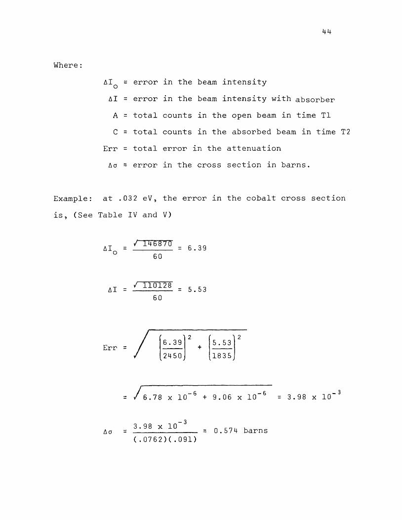
Where:
~Io = error l.n the beam intensity
~I = error in the beam intensity with absorber
A = total counts in the open beam in time Tl
c = total counts l.n the absorbed beam in time T2
Err = total error l.n the attenuation
~a = error in the cross section l.n barns.
Example: at .032 eV, the error in the cobalt cross section
is, (See Table IV and V)
~I =
I 146870
60
I 110128
60
= 6.39
= 5.53
Err =I [~J 2
+ [ 5 • 53 r 2450 1835;
= ;I 6.78 X 10- 6 + 9.06 X 10- 6
~a = 3.98 X 10- 3
(. 0762) (. 091) = 0.574 barns
-3 = 3.98 X 10

45
VI. CONCLUSIONS AND RECOMMENDATIONS
A neutron chopper provides a means for directly
measuring the neutron-energy distribution in a beam of
slow neutrons. This spectrum contains sufficient resolu
tion to permit accurate energy dependent cross section
measurements within a certain energy range.
At high energ1es the resolution becomes poor and
limits the effectiveness of the results. At low energies
the chopper begins to attenuate neutrons near the cut
off velocity and therefore the low energy region is af
fected. The chopper will obtain useful results over
about one and one half energy decades. This useful range
can be moved up or down the energy scale by varying the
chopper speed.
Another limitation on the chopper is the availability
of neutrons at a particular energy. In order to produce
good statistics, a large number of neutrons must be avail
able in the beam at that energy.
The motor bearings should be taken down and lubricated
after 10 7 revolutions or after about 100 hours of normal
use. If the chopper is operated at high speeds for ex
tended periods the brushes in the motor will probably need
replacing at this time also.
All screws and bolts should be checked before each
experiment. A serious accident could result if the chopper
becomes unbalanced at 10,000 rpm because of the loss of

46
a set screw. In order to maintain balance all screws in
the chopper and shaft connector must be returned to their
exact position if the device is disassembled.
Once the collimators are aligned, the alignment
will remain constant only as long as the thermal column
door remains undisturbed. If the door is moved, the
system is subject to misalignment because of the loose
motion in the wheels which support the door. It is recom
mended that either the loose motion be corrected or that
an easy alignment method be developed.

47
BIBLIOGRAPHY
l. L. W. Alvarez, PHYSICS REVIEW 54, 609 (1938)
2. W. B. Jones, Jr., PHYSICS REVIEW 74, 364 (1948)
3. J. Rainwater and W. W. Havens, Jr., PHYSICS REVIEW 70, 136 (1946)
4. D. J. Hughes, Pile Neutron Research, Addison-Wesley Co. , ( 19 53)
5. Jon Spalek, ANL 6990 Chapter 30, January,(l965)
6. Dunning, Pergram, Fink, and Mitchell, PHYSICS REVIEW, 48, 704 (1935)
7. R. Ringo, unpublished Argonne work (1950)
8. E. 0. Wollan, unpublished Oak Ridge work (1949)
9. A. W. McReynolds, PHYSICS REVIEW, 86, 504 (1952)
10. John W. Chastain, U.S. Research Reactor Operation and Use, Addison-Wesley Co. (1958)
11. Seidl, Palevsky, Randall, and Thorne, PHYSICS REVIEW, 82, 345 (1951)
12. T. Brille and H. Lichtenberger, PHYSICS REVIEW, 72, 558 (1947)
13. P. A. Egelstaff and B. T. Taylor, NATURE, 166, 825
14. A. w. McReynolds, PHYSICS REVIEW, 8 8' 950 (1952)
15. P. A. Egelstaff, NATURE (London) 168, 290 (1951)
16. Carter, Palevsky, Myers, Hughes, PHYSICS REVIEW, 9 2' 716 (1953)
17. D. A. Hughes and H. Palevsky, PHYSICS REVIEW, 92, 1206 (1953)
18. R. E. Schmunk, P. D. Randolph, R. M. Brugger, NUC. SCIENCE & ENG., 7, 193 (1960)
19. R. S. Stone, R. E. Slovek, NUC. SCIENCE & ENG., 6, 466 (1959)
20. Emilio Segre, Nuclei and Particles, Benjamin, N.Y., (1965)
(1950)

48
21. S. Glasstone and A. Sesonske, Nuclear Reactor Engineering, Van Nostrand (1963)
22. R. V. Meghreblian, D. K. Holmes, Reactor Analysis, McGraw Hill, (1960)
23. J. B. Haag, Nuclear Reactor Experiments, Van Nostrand (1950)
24. Borst, Ulrich, Osborne, Hasbrouck, PHYSICS REVIEW, 70, 557 (1946)
25. A. W. Merrison, E. R. Wiblin, NATURE, (LONDON) 167, 346 (1951)
26. P. A. Egelstaff, Thermal Neutron Scattering, Academic Press,(l965)
27. General Electric Neutron Pulser, Drawing T 7149733, (1962)
28. F. A. Valente, A Manual of Experiments in Reactor Physics, Macmillan, (1963)
29. Brookhaven National Laboratories Blue Prints, P2-23 Series (1958)
30. T. L. Isenhour and G. H. Morrison, ANALYTICAL CHEMISTRY, 38, 162 (1966)
31. D. J. Hughes and R. B._Schwarts, Neutron Cross Sections BNL 325,(1958)
49
APPENDIX I
Detailed Operating Procedure
This section is an attempt to provide a set of instruc
tions which will enable the undergraduate to operate the
equipment without a complete understanding of all the in
strumentation. There is no attempt to be complete in every
detail and no claim is made that this procedure is superior
to any other. In addition to the operating procedure, the
following suggestions are given so that the experimenter
need not duplicate the mistakes of the author.
Suggestions. The triggering pulse produced by the
photocell and amplified by the pulse amplifiers should
occur at the exact instance the chopper is opened if
accurate energy determinations are to be made. It is
impossible to set this timing pulse by any static method
since the photocell output varies with the speed of the
chopper. The photocell does not produce its sharpest
rise time at maximum intensity in the rotating light beam.
The triggering pulse actually occurs about 2 to 5 degrees
before the light beam reaches maximum intensity.
The author suggests that the experimenter establish
the zero timing by one of two methods. (1) Use a strobo
scope which can be externally triggered by the pulse fed
to the analyzer and adjust the timing until the chopper
lS opened as the strobe flashes. (2) Measure the cross
section of nickel and use the known peaks in the cross
section curve as calibration points.

The following instructions consist of two parts:
(1) general instructions for operating the chopper and
(2) instructions for cross section measurement.
Operating Procedure
50
(1) Connect cable leading to the multichannel analyzer
(MCA) as shown in the block diagram in Fig. 12.
(2) Check all the bolts and set screws ln the chopper
shaft connector, rotating mirror, and chopper mounts.
(3) Check the alignment of the chopper with the neutron
beam.
(4) Position the BF3
chamber as accurately as possible
2 meters from the chopper.
(5) With the reactor operating at one kilowatt, rotate
the chopper slowly by hand until the largest neutron
count rate is observed.
(6) Check the position of the BF3
counter by moving it
until the largest count rate is observed.
(7) Clean the dust from the rotating mirror.
(8) Start the chopper motor (at a low speed setting) and
then turn on the tachometer and light source.
(9) Allow the chopper to operate for five minutes before
attempting to set the speed.
(10) Turn on the pulse amplifier and oscilloscope and check
the o.utput pulse. The pulse must have a lOv peak
and a rise time of l ~ sec.

51
(11) The tachometer can now be calibrated using the scaler
output as a standard. Note that two pulses are re
ceived for each revolution.
(12) Set the MCA to operate on 50 or 100 channels and the
time base generator to operate at 12.5, 25, or 50
microseconds as desired.
(13) Make the necessary calculations to determine if the
total channel scan time can be included in l/2 revolu
tion of the chopper.
EXAMPLE: 25 ~ sec per channel + 12.5 ~ sec dead time
per channel = 37.5 ~ sec per channel.
37.5 ~ sec x 100 channels = 3750 ~ sec or
3. 7 mJ.~ec.
Chopper speed: 100 rev sec or 0.01 sec per
revolution or 0.005 sec per
l/2 revolution = 5.0 m sec.
Because 3.7 is less than 5 this combination
is possible. Note that 50 ~ sec per channel
would not work under these conditions.
(14) Set the MCA gain to l/8 and turn the threshold, upper
level, and sensitivity controls fully clockwise.
(15) Make the other necessary changes to permit the MCA
to operate with external control 1n the time mode.
(16) Disconnect the input cable from the internal amplifier
and read the total instrument noise with the chopper
operating. Reduce the sensitivity just enough to
reduce the instrument noise to zero.

52
(17) Reconnect the input cable and measure the chopper and
amplifier no1se with the preamp ON and the neutron beam
OFF. The no1se should not be more than 100 counts
per minute. If the noise is excessive, reverse the
power plug at the isolation transformer on the chopper
speed controller and make sure all ground connections
are made. See Fig. 12.
(18) With the reactor operating, open the neutron beam
and start the MCA.
(19) A Maxwellian distribution should be observed 1n about
30 seconds. See Fig. 8.
NOTE: About 5 hours warm up time is required for the tacho
meter. However, the tachometer need not be operated during
this time because the warm up is due to the tubes in the
scaler below the tachometer circuit. The motor and tachometer
circuit need about 30 minutes to stabilize if the scaler
has been left on over night.
53
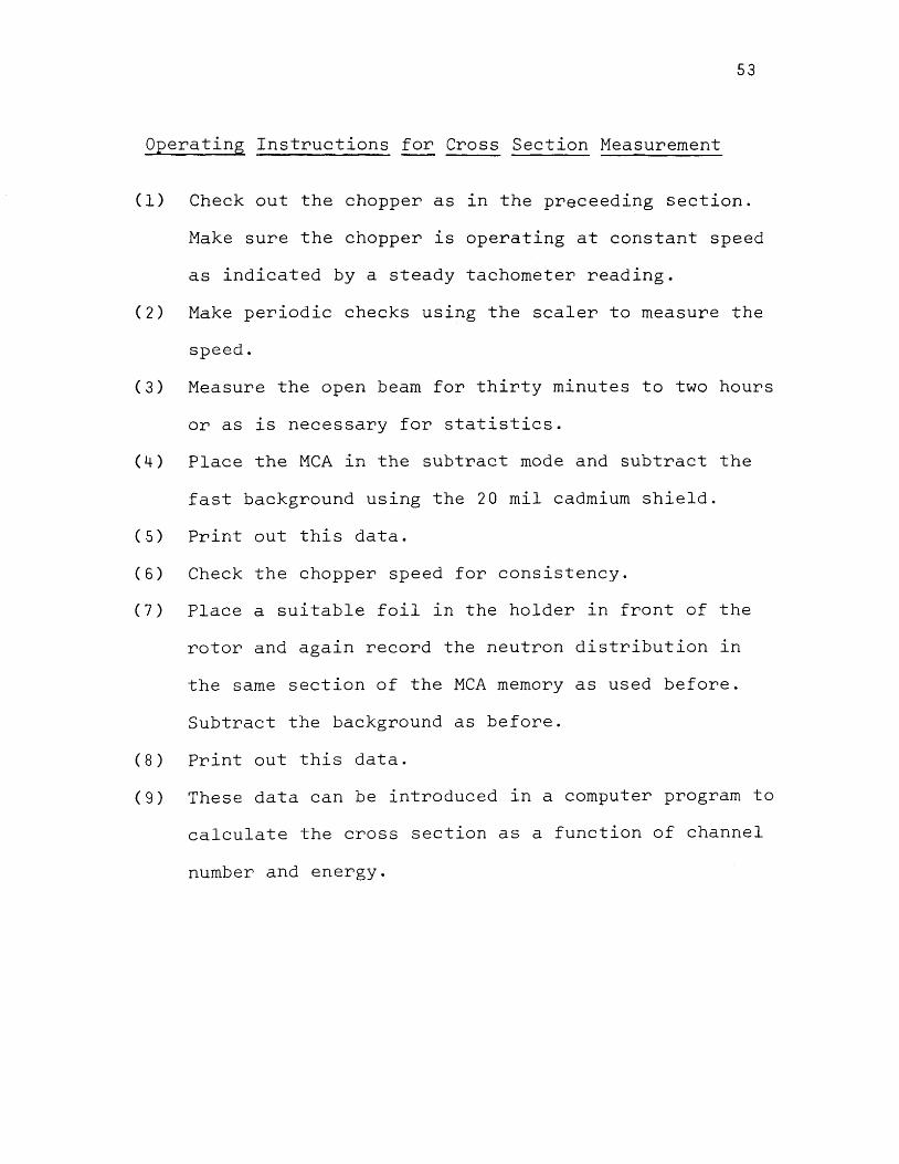
Operating Instructions for Cross Section Measurement
(1) Check out the chopper as in the preceeding section.
Make sure the chopper is operating at constant speed
as indicated by a steady tachometer reading.
(2) Make periodic checks using the scaler to measure the
speed.
(3) Measure the open beam for thirty minutes to two hours
or as is necessary for statistics.
(4) Place the MCA in the subtract mode and subtract the
fast background using the 20 mil cadmium shield.
(5) Print out this data.
(6) Check the chopper speed for consistency.
(7) Place a suitable foil in the holder in front of the
rotor and again record the neutron distribution ln
the same section of the MCA memory as used before.
Subtract the background as before.
(8) Print out this data.
(9) These data can be introduced ln a computer program to
calculate the cross section as a function of channel
number and energy.

54
TABLE III
LIST OF APPARATUS
(1) Neutron Chopper including rotor, electric motor, and
photo timing mechanism
(2) Chopper speed controller (Figs. 9, 14)
(3) Tachometer (Figs. 9, 15)
(4) BF 3 Proportional counter, Reuter-Stokes RSN-44A-MG
(5) High voltage power supply, Tracerlab 2500
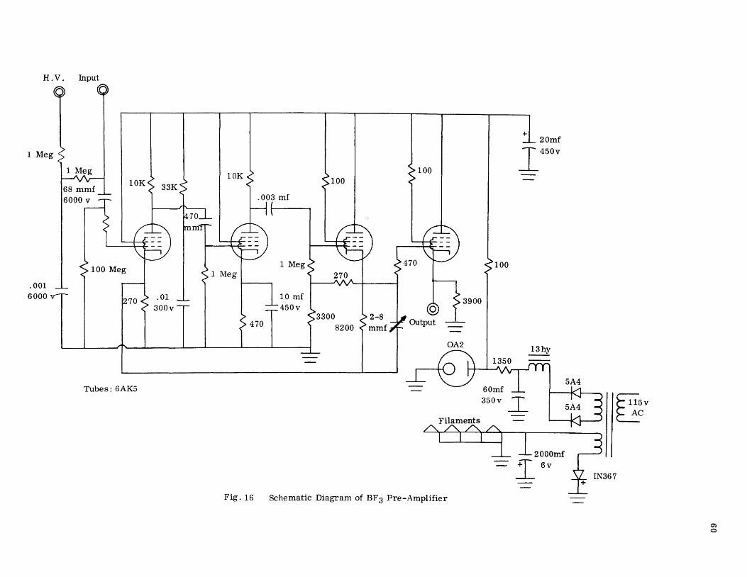
(6) Pre-amplifier for proportional counter (Figs. 5, 16)
(7) Two pulse amplifiers, RIDL 30-19 and 33-12
(8) Oscilloscope, Tektronix 515-A
(9) Scaler, NRD 320-0A2
(10) Multi-channel Analyzer, RIDL 34-12B
(11) X-Y Recorder, F. L. Moseley 2D-2
(12) Time base generator, RIDL 54-6
(13) Isolation Transformer llSV @Sa
(14) Neutron collimators and shutter
(15) Hand held neutron monitor, Nuclear-Chicago DN3
(16) Hand held gamma monitor, Technical Associates CP-4A

55
APPENDIX II
Schematic and Block Diagrams of Neutron Chopper Circuits
The following section includes block diagrams showing
cable connections of all the circuits used in this work.
Reference should be made to the manufactor's operating
instructions in using the commercial equipment. Schematic
diagrams are also provided for all circuits which were
designed and constructed for this work.
Some of this equipment is not foolproof and if cables
are connected to an improper outlet, the circuit could be
damaged. This is particularly true of the tachometer
circuit.

Regulator
135 v Battery
9V Battery
B"F3 Counter
RG-8
"Fig. 12
Isolation Transformer -
9 V Byp
RG62U det.
In
Speed Control
L.V.M.
Line V. Meter
Scaler (H. V. Off)
Out RG59U
_4__CI .J.
Cable
Photo Cell
Out
----~-40ft.
D.C. By-Pass
Earth Ground "For Noise Suppression
Wiring Diagram l<'or Complete System
Motor
56
Direct Conv.
I 40ft _j
lRG59U I Ext.
Start f
Time Base Generator

RIDL 54-6
Det Gate
t
Osc
Ext Live Time
RIDL 34-12B
57
To F3 Pre-Amp
Time Base Generator Multi -Channel Analyser
Gain 1/8 Threshold 1 000 Upper Level 11 00 Time Mode Sensitivity- as necessary to eliminate Time Base Generator noise
Fig. 13 Connection Diagram for Multi-Channel Analyser

To Motor
Fl F2 ~------------------------~ r-------------------~
~ ~ Isolation
P 1- Speed Control P 2- Fine Speed Adjustment
1.5K lOW
1 K lW
Note: Circuit is isolated from chassis to reduce noise in other amplifiers
"Fig. 14
10 Turn Pot
Al A2
IN6050 lOmf 25v
lK 2W
2Nl846A
P2 5K
Field
F1! "f} ___ ::J _ ___, All ~2
OJ Armature
Schematic Diagram of the Speed Controller
Motor

To Photo Cell l35v
0 l[l~o~ P3 lOK 3
_L 'V'v
B
Pulse Outputs
-A
__C--1 A- Pulse output to first pulse amplifier (to trigger analyser) B- Not used P 1- Determines the input pulse height to Q 1 P 2- Determines the meter calibration P 3- Determines the height of the output pulse at A and B
Fig. 15 Schematic Diagram of Tachometer
lOOK
Pl
5A4
0-200ma Speed Indicator
H .V. Input
1 Meg
.001 6000 v
Tubes: 6AK5
100 100
Fig. 16 Schematic Diagram of BF3 Pre-Amplifier
100
3900
+ 20mf I450v
EU5v 2c

61
APPENDIX III
Computer Program and Cross Section Data
This section provides the computer program used to
obtain the results in this paper. Included is a sample
input data sheet and a sample computer output. These
data correspond to the data presented in Section V.

TABLE IV
COMPUTER PROGRAM TO CALCULATE CROSS SECTIONS
*LIST PRINTER C C***64933NE490E MOBLEY C M 07/08/66 FORTRAN 2 C CROSS SECTION BY NEUTRON CHOPPER
DIMENSION A(l00),S(l00) 9 C(l00),P(l00),E(l00),0S(l00) READ lOO,W,X,Y,TC READ lOO,Tl,T2
C W=ATOMS/CC X=SAMPLE THICKNESS C Y=PATH LENGTH TC = TIME PER CNANNEL
READ 2 00 , ( A ( I ) , I = 1, 9 9 ) C A= TOTAL NEUTRONS , NO ABSORBER, NO FILTER C I= CHANNEL NUMBER
READ 200,(C(I),I=l,99l C C= TOTAL NEUTRONS, WITH ABSORBER, NO FILTER
DO 50 I= 1, 99 F=(A(l)/Tl) FO=C(l)IT2
C F= NET COUNTING RATE WITH SAMPLE C FO= NET COUNTING RATE W/0 SAMPLE
z =1-1 E(I )=(YI(5.7+TC/2.+(TC*Z)+(l2.5*Z)) l**2/1.92E-04
C E= ENERGY AS FUNCTION OF CHANNEL NUMBER S(I )=LOGFtFIFO)/(W*X)
C S= MICROSCOPIC CROSS SECTION 0 F = SQ R T F ( A ( I ) ) I T 1 DFO=SQRTF tC (I)) /T2 ERR=SQRTF((DFIF)*(DF/F)+(DFO/FO)*(DFO/FO)) DS(I )=ERRI(W*X)
50 P (I )=FIFO PRINT 300 PRINT 400, (I, P (I), E (I), S (I), OS (I), I= 1, 99) CALL EXIT
100 FORMATtlOX,5Fl0.5) 200 FORMATt6X,9F7.0)
62
300 FORMAT (12H CHAN NUMBER,4X,llHATTENUATION,5X7H ENERGY,8X 2 9 5HBARNS,7X,5HERROR 1/)
400 FORMAT(8X,I4,4Fl4.7) END

TABLE V
INPUT DATA~': FOR COBALT CROSS SECTION
Nuclei per Unit Vol. Thickness Flight Distance Channel Width x lo- 24 (ern) (rn) (].l sec)
.091 .0762 2 . 0 25.0
Counting Time (min)
Open Absorber
60.00000 60.00000
Counts Recorded per Channel COJ2en)
14150. 25412. 57786. 109203. 170602. 227797. 273277. 304322. 322158.
326839. 324086. 314806. 301387. 285191. 268648. 250978. 230771. 213251.
195752. 178847. 163064. 146870. 133119. 120316. 108336. 97711. 88994.
80739. 72929. 65418. 57928. 52073. 47030. 42933. 38882. 34970.
31257. 27690. 24958. 22387. 19914. 18045. 16278. 14847. 13244.
11724. 10646. 9568. 8807. 8293. 7534. 6953. 6594. 6126.
5401. 5060. 4290. 4107. 3996. 3542. 3274. 2978. 2643
2485. 2263. 1971. 1927. 1546. 1567. 1514. 1370. 1224.
1038. 983. 912. 8 3 5. 721. 639. 654. 580. 497. m w
497. 3 9 9. 455. 318. 299. 308. 289. 310. 255.
2 3 6. 92. 170. 215. 245. 2 3 8. 114. 131. 42.

Table V (Cont'd)
Counts Recorded per Channel (Absorber)
11957. 22678. 50504. 95345. 148670. 197759. 236909. 262797. 276129.
279680. 275386. 264516. 251689. 235803. 218547. 202273. 184499. 167448.
151482. 137356. 123058. 110128. 97725. 87133. 77879. 69280. 62998.
56330. 49637. 44341. 39401. 34435. 30729. 27813. 24156. 21840.
19392. 17162. 15326. 13373. 12047. 10509. 9545. 8484. 7840.
7039. 6063. 5383. 5103. 4539. 4248. 3770. 3608. 3509.
2805. 2726. 2505. 2313. 2011. 1769. 1683. 1432. 1329.
1264. 1145. 1002. 919. 926. 840. 729. 587. 592.
454. 462. 428. 331. 320. 404. 295. 2 94. 213.
232. 242. 145. 161. 126. 146. 101. 122. 84.
88. 118. 105. 106. 3 6. 2 . 102. 9 6. 7 0.
*each line contains the data on one computer card.

65
TABLE VI
COMPUTER OUTPUT DATA FOR COBALT CROSS SECTIONS
CHAN
NUMBER ATTENUATION ENERGY BARNS ERROR (cr)
1 1.1834071 62.8949680 24.2850860 1.7914007 2 1.1205573 6. 7150359 16.4151810 1.3173743 3 1.1441865 2. 3984292 19.4245760 .8784632 4 1.1453458 1. 2195 722 19.5706200 .6391973 5 1.1475213 • 7363880 19.8442810 .5116586 6 1.1518919 .4923684 20.3925060 .4432409 7 1.1535104 • 3522342 20.5949940 • 4048 326 8 1.1580117 .2644075 21.1566550 • 384028 7 9 1.1666938 • 205 7587 22.2338450 .3739968
10 1.1686176 .1646610 22.4 7144 70 .3714737 11 1.1768427 • 134 7509 23.4829060 .3737549 12 1.1901208 .1123075 25.1009210 .3803786 13 1.1974579 .0950376 25.98 72640 • 38 94050 14 1.2094460 .0814653 27.4238410 .4014000 15 1.2292458 .0706056 29.7656260 .4154232 16 1.2407884 .0617810 31.1134630 .4309096 17 1. 2507981 .0545130 32.2721900 .4503822 18 1.2735356 .0484560 34.8702040 .4 708785 19 1.2922459 .0433552 36.9735090 .4934931 20 1.3020690 .0390193 38.0656060 .5173946 21 1.3250987 .0353028 40.5940030 .5445594 22 1.3336299 .0320931 41.5194930 .5748480 23 1.3621796 .0293020 44.5 741480 .6074912 24 1.3808316 .0268597 46.5354210 .6415141 25 1. 3910810 • 024 7106 4 7.6019060 .6775079 26 1.4103781 .0228094 49.5886790 • 7162662 27 1.4126480 .0211195 49.8205920 • 7508 794 28 1.4333215 .0196107 51.9157890 .7917018 29 1.4692467 • 0182 5 80 55.4858260 .8391425 30 1.4753388 .o 17040 5 56.0825540 .8870994 31 1.4702164 .0159409 55.5809750 .9417310 32 1.5122113 .0149444 59.6424980 1.0016717 33 1.5304760 .0140385 61.3738840 1.0578333 34 1.5436306 .0132125 62.6081110 1.1100307 35 1.6096207 .01245 73 68.6450570 1.1814572 36 1.6011904 .0117651 67.8877660 1. 243 7751 37 1. 6118 502 • 01112 90 68.8446690 1.3182692 38 1.6134483 .0105432 68.9875810 1.4010353 39 1.6284745 .0100024 70.3244320 1.4799620 40 1.6740447 .0095022 74.3045580 1.5761225 41 1. 6530256 .0090385 72.4823 770 1.6645431 42 1.7170996 .0086080 77.9666850 1.7696114 43 1.7053954 .0082076 76.98032 70 1.9591671 44 1.7500000 .0078344 80.703 7260 1.9626848

66
Table VI (Cont'd)
45 1.6892857 .0074862 75.6115730 2.0550030 46 1.6655774 .oo 71606 73.5 732810 2.1745096 47 1.7558964 .0068558 81.1888160 2.3202875 48 1.7774475 .0065 701 82.9480450 2.4570610 49 1.7258475 .0063019 78.6995220 2.5371163 50 1.8270544 .0060498 86.9177480 2.6626548 51 1.7735404 .0058125 82.6306950 2.7669927 52 1.8442970 .0055889 88.2 72 3550 2.9167885 53 1.8276052 .0053779 86.9612160 2.9863348 54 1.7457964 .0051787 80.3569030 3.0531581 55 1.9254901 .0049904 94.4853810 3.3563390 56 1.8561995 .0048121 89.2000670 3.4262780 57 1.7125748 .0046432 77.5861620 3.6263172 58 1.7756160 .0044831 82.7993710 3. 74904 73 59 1.9870711 .0043311 99.0253720 3. 9428807 60 2.0022611 .004186 7 100.12 36000 4.1985908 61 1.9453356 .0040494 95.9641340 4.3254536 62 2.0796089 .0039188 105.5896600 4.6375545 63 1.9887133 .0037943 99.1445060 4.8495021 64 1.9659810 .0036757 97.4865660 4.9822394 65 1.9764192 .0035626 98.2502260 5.2300806 66 1.9670659 .0034546 97.5661270 5.5953065 67 2.0968444 .0033515 106.7799500 5.7812592 68 1.6695464 .0032529 73.9165250 5.9926321 69 1.8654762 .0031586 89.9190020 6.1669086 70 2.0768175 .oo 30683 105.3959600 6.5011705 71 2.3339012 .0029819 122.22 62400 7.1140954 72 2.0675676 .0028990 104.7522100 7.21954 76 73 2.2863437 .0028196 119.2 5 72 8 00 8.1144941 74 2.1277057 .002 7434 108.8870000 8.13466 75 75 2.1308410 • 0026 702 109.0993500 8.4496106 76 2.5226585 .0025999 133.4419600 9.3668949 77 2.2531249 .0025324 117.1466100 9.6869341 78 1.5816831 .0024675 66.1200320 9.1665234 79 2.2169491 .0024050 114.8123700 10.1143230 80 1.9727889 .0023448 97.9850910 10.3245630 81 2.3333332 .0022869 122.1911300 11.8104050 82 2.1422413 .0022311 109.8688500 11.4668780 83 1.6487603 .0021774 72.1097840 11.7500170 84 3.1379310 .0021255 164.9164400 13.7527490 85 1.9751553 .0020755 98.15 79740 13.9490570 86 2.3730158 .0020272 124.6231100 15.3171220 87 2.1095890 .0019806 107.6538200 14.4903780 88 2.8613861 .0019356 151.611 73 00 16.6696410 89 2.5409835 .0018921 134.4857600 15.4129110
90 3.0357143 .0018500 160.1405600 18.1423560 91 2.6818182 .0018094 142.2651400 18 .o 126960

67
APPENDIX IV
Hazard Analysis for Use of the Neutron Chopper
Neutrons. The nature of this experiment requires
that a beam of neutrons be brought out of the thermal
column into the experimental area. This is accomplished
by removing one of the graphite stringers and allowing a
collimated partially moderated beam of neutrons 1 1/2 by
3 inches to enter the room. The flux in this beam is
approximately 107
neutrons per square centimeter per second.
This beam emerges from the thermal column and passes
through the rotating chopper which is constructed of stain
less steel which has been cadmium plated, aluminum, and
ordinary steel. The initial collimation is accomplished
by a 1 1/2 x 3 in. hole cut into cadmium which is located
about two feet within the thermal column door. Additional
collimation is accomplished by a sheet of boral which is
bolted to the door and another cadmium baffle located about
one inch from the chopper. After passing through the
baffles, neutron chopper, and detector tube, the remainder
of the beam travels to the beam catcher which is made of
.15 lb. boric acid per lb. of paraffin. The neutron beam
should be completely absorbed ln the catcher.
The neutron beam will cause activation of the air
through which it passes. It has been estimated*that the
activity of the room air would be approximately 10-7
mc/ml.
*Presented to the Reactor Safety Committee, May, 1966.

68
which is less than the permissible concentration permitted
by AEC regulations. Almost all the neutron scattering
around the chopper components occurs throughout a small
angle in the vertical direction. Negligible neutron scat
tering exists to the sides of the chopper. However, as
a safety precaution against scattered neutrons and gamma
activity the control panel is located some 15 feet away
from the chopper.
Gamma rays. The gamma intensity in the neutron beam
1s approximately 650 mr/hr and some neutron-gamma activa
tion exists in the chopper components and in the neutron
catcher. This gamma activity (outside of the beam) is less
than 1 mr at 3 feet.
Radiation measurement. A monitor for gamma radiation
1s mounted on the east wall of the experimental room. This
gives an annuciation and a rundown when the level exceeds
ten mr per hour. A neutron monitor is also installed 1n
the experimental room and is monitored in the reactor con
trol room.
Neutron and gamma hand survey equipment is provided in
the experimental room for the purpose of personnel safety.
The neutron beam is turned on or off by an absorbing shutter
made of 4 in. Poly-B, 60 mil cadmium and 1/2 in. lead. This
shutter which is located two feet within the thermal column
door can be raised or lowered by a cable extending through

69
the door. The gamma beam lS controlled by a four inch lead
brick which is mounted in front of the beam port. It is
proposed that an automatic sliding absorber be installed
which is controlled from the control room and connected to
the already existing rotating red beacon which would come
on automatically when the beam is open.

70
VITA
The author was born on July 14, 1940 in Reidsville,
Georgia. He received his elementary and secondary educa
tion in the schools of Glennville, Georgia. In 1961 he
received his A.S. in Electronics from the Southern Tech
nical Institute, Marietta, Georgia and ln 1963 his B.S.
in Physics from Oglethorpe University, Atlanta, Georgia.
He has taught Physics for two years at Southern
Technical Institute while simultaneously serving as Faculty
Research Associate at the Georgia Institute of Technology,
Atlanta, Georgia.
He entered the Graduate School of the University of
Missouri at Rolla in September 1965 as a candidate for
the degree of Master of Science in Nuclear Engineering.