Embed Size (px)
Citation preview
October 1999
THE CONFEDERATED TRIBES OF THE WARM SPRINGSRESERVATION OF OREGON JOHN DAY BASIN OFFICE
FY 1998 WATERSHED RESTORATION PROJECTS
THIS IS INVISIBLE TEXT TO KEEP VERTICAL ALIGNMENT THIS IS INVISIBLE TEXT TO KEEP VERTICAL ALIGNMENT THIS IS INVISIBLE TEXT TO KEEP VERTICAL ALIGNMENT THIS IS INVISIBLE TEXT TO KEEP VERTICAL ALIGNMENT THIS IS INVISIBLE TEXT TO KEEP VERTICAL ALIGNMENT
Annual Report 1998
DOE/BP-00000492-1

This report was funded by the Bonneville Power Administration (BPA), U.S. Department of Energy, aspart of BPA's program to protect, mitigate, and enhance fish and wildlife affected by the developmentand operation of hydroelectric facilities on the Columbia River and its tributaries. The views of thisreport are the author's and do not necessarily represent the views of BPA.
This document should be cited as follows: Robertson, Shawn - The Confederated Tribes of the Warm Springs Reservation, The Confederated Tribes of the WarmSprings Reservation of Oregon John Day Basin Office FY 1998 Watershed Restoration Projects, Annual Report, Reportto Bonneville Power Administration, Contract No. 00000492, Project No. 199801800, 35 electronic pages (BPA ReportDOE/BP-00000492-1)
This report and other BPA Fish and Wildlife Publications are available on the Internet at:
http://www.efw.bpa.gov/cgi-bin/efw/FW/publications.cgi
For other information on electronic documents or other printed media, contact or write to:
Bonneville Power AdministrationEnvironment, Fish and Wildlife Division
P.O. Box 3621905 N.E. 11th Avenue
Portland, OR 97208-3621
Please include title, author, and DOE/BP number in the request.
The Confederated Tribes of the Warm Springs Reservation of
Oregon
John Day Basin Office
FY 1998 Watershed Restoration Projects
Annual Report
Prepared by:
John Day Basin Office &
Grant Soil and Water Conservation District
Prepared for:
U.S. Department of Energy Bonneville Power Administration
Environment, Fish and Wildlife Division
Project Number: 98-018-00
Contract Number: 98BI-09782
21 October 1999
Table of Contents
TABLE OF CONTENTS II
TABLE OF FIGURES III
TABLE OF PHOTOS III
ABSTRACT IV
PROJECT DESCRIPTIONS 1
PROJECT: FIELD TAILWATER REUSE & INFILTRATION GALLERY 1 PROJECT: PAGE IRRIGATION CONVERSION 4 PROJECT: CLAUSEN PUMPING STATION & IRRIGATION UPGRADE 6 PROJECT: ENTERPRISE DIVERSION 8 PROJECT: LEE IRRIGATION CONVERSION 11 PROJECT: PIKE IRRIGATION CONVERSION & PUMPING STATION 13 PROJECT: MORRIS IRRIGATION CONVERSION & PUMPING STATION 16 PROJECT: CROWN RANCH DIVERSION 17 PROJECT: HOLMES PIPELINE 19 PROJECT: RUDISHAUSER INFILTRATION GALLERY 22
ATTACHMENT 1 25 FISCAL YEAR 1998 PROJECT BUDGETS 25
ENDNOTES 26
ii
Table of Figures Figure 1. Map of the John Day Basin ............................................................ v Figure 2. Upper Mainstem John Day River Project Location Map...........................vi Figure 3. Upper Middle Fork Project Location Map ..........................................vii Figure 4. Field Project Location Map ........................................................... 1 Figure 5. Fields Project Facility Map............................................................ 2 Figure 6. Page Project Location Map............................................................ 4 Figure 7. Page Project Facilities Map ........................................................... 5 Figure 8. Clausen Project Location Map ........................................................ 6 Figure 9. Enterprise Project Location Map..................................................... 8 Figure 10. Lee Project Location Map...........................................................11 Figure 11. Pike Project Location Map..........................................................13 Figure 12. Pike project facilities map .........................................................14 Figure 13. Morris Project Location Map........................................................16 Figure 14. Crown Ranch Project Location Map ...............................................17 Figure 15. Holmes Project Location Map ......................................................19 Figure 16. Holmes project facilities map......................................................20 Figure 17. Rudishauser Project Location Map ................................................22 Figure 18. Rudishauser project facilities map ................................................24
Table of Photos
Photo 1. Pre-project photo of the Fields Diversion........................................... 1 Photo 2. Well screens being installed at the Fields project................................. 3 Photo 3. Post-project photo of Fields Infiltration Gallery................................... 3 Photo 4. Pre-project photo of the Enterprise Diversion ..................................... 9 Photo 5. Post-project photo of the Enterprise diversion ...................................10 Photo 6. Pre-project photo of Morris/Pike Diversion........................................13 Photo 7. Pike Pumping Station ..................................................................15 Photo 8. Morris Wheelline .......................................................................16 Photo 9. Pre-project photo of Crown Ranch Diversion......................................17 Photo 10. Pre-project photo of Holmes Diversion ...........................................19 Photo 11. Holmes pipeline crossing during excavation.....................................21 Photo 12. Rudishauser well screens during excavation .....................................23
iii

Abstract
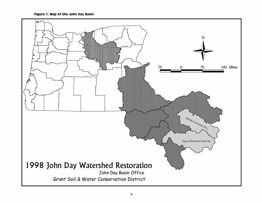
The John Day River is the second longest free-flowing river in the contiguous United States and one of the few major subbasins in the Columbia River basin containing entirely unsupplemented runs of anadromous fish. Located in eastern Oregon, the basin drains over 8,000 square miles, the fourth largest drainage area in Oregon. With its beginning in the Strawberry Mountains near the town of Prairie City, the John Day flows 284 miles in a northwesterly direction, entering the Columbia River approximately four miles upstream of the John Day dam. With wild runs of spring chinook salmon and summer steelhead, red band, westslope cutthroat, and redband trout, the John Day system is truly one of national significance. The entire John Day basin was granted to the Federal government in 1855 by the Confederated Tribes of the Warm Springs Reservation of Oregon (Tribes). In 1997, the Tribes established an office in the basin to coordinate restoration projects, monitoring, planning and other watershed activities on private and public lands. Once established, the John Day Basin Office (JDBO) initiated contracting the majority of its construction implementation actions with the Grant Soil and Water Conservation District (GSWCD), also located in the town of John Day. The GSWCD completes the landowner contact, preliminary planning, engineering design, permitting, construction contracting, and construction implementation phases of the projects. The JDBO completes the planning, grant solicitation/defense, environmental compliance, administrative contracting, monitoring, and reporting portion of the program. Most phases of project planning, implementation, and monitoring are coordinated with the private landowners and basin agencies, such as the Oregon Department of Fish and Wildlife and Oregon Water Resources Department. In 1998, the JDBO and GSWCD proposed continuation of a successful partnership between the two agencies and basin landowners to implement an additional ten (10) watershed conservation projects. The types of projects implemented included installation of a tailwater collection and reuse system, infiltration galleries, permanent diversions, pumping stations, and irrigation upgrades. Project costs in 1998 totaled $891,504.00 with a total amount of $300,329.00 (34%) provided by the Bonneville Power Administration (BPA) and the remainder coming from other sources such as the Bureau of Reclamation (BOR) and individual landowners.
iv
v
1998 John Day Watershed RestorationJohn Day Basin Office
Grant Soil & Water Conservation District
N
Upper Mainstem John Day
Middle Fork John Day
70 0 70 140 Miles
Figure 1. Map of the John Day Basin
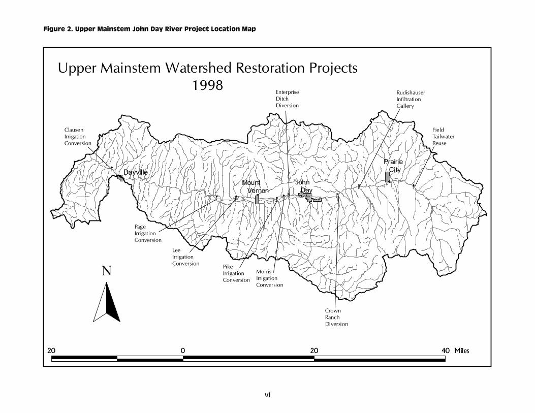
Figure 2. Upper Mainstem John Day River Project Location Map
bb bb
b b
b
b
b
PikeIrrigation Conversion
MorrisIrrigationConversion
CrownRanchDiversion
EnterpriseDitchDiversion
ClausenIrrigationConversion
RudishauserInfiltrationGallery
FieldTailwaterReuse
LeeIrrigation Conversion
PageIrrigation Conversion
Joh n DayJohn Day Ri ver
L uce
Cree k
Can
yon C
r
Dav
is Cr
Dam
on C
reek
Jo h
n Day
R iver
Clar
k Cre
e k
Mc
C lella
n C
reek
Ril
ey Cr
eek
Pa na ma D itc h
John D a
y Riv er
Wi
nega
r Gulc
h
Ish a
m Cr eek
John D
ay Riv
er
Eddin gto n
D tic h
Blu e Mt. Di tch
Grav
eyard
Gul
ch
Wate
rspou
t Gul
ch
Warr e
ns Cre
e k
Pic
nic C r
eek
Da yv ille
Fer
ris Cre
e k
Fra
nks C
reekJ
oh n D a
y Rive r
Jo hn Da y R iv e
r
Qua
rtz G
ulch
La yco ck -L on g D itc h
Jo hn Da y
R iv er Disse
l Cre
ek
De an Cr ee k
Gru b Cr ee k
Castl e C
reek
Be
a r Cr
eek
Jo hn
Da y Riv er
Fisk Cr
eek
Pin
e Cre
ek
India
n Cre
e k
John Day
Mount Vernon
Prairie CityDayville
20 0 20 40 Miles
N
Upper Mainstem Watershed Restoration Projects1998
vi

vii
Figure 3. Upper Middle Fork Project Location Map
b
LongCreek
HolmesDiversion
Mid dle Fo
rk Joh n D
ay Rive r
Ca
mp C
r eek
20 0 20 Miles
N
Upper Middle Fork Watershed Restoration Projects1998
Page 1 John Day Basin Office FY 1998 Watershed Restoration Projects
Project Descriptions
PROJECT: FIELD TAILWATER REUSE & INFILTRATION GALLERY
Grantee: Grant Soil and Water Conservation District
b
John Day River
Win
egar
Gul
ch
Isham Cree
k
0.7 0 0.7 1.4 Miles
N
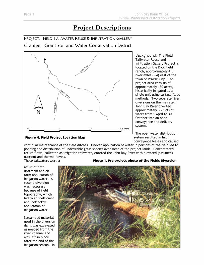
Background: The Field Tailwater Reuse and Infiltration Gallery Project is located on the Dick Field ranch, approximately 4.5 river miles (RM) east of the town of Prairie City. The project area consists of approximately 130 acres, historically irrigated as a single unit using surface flood methods. Two separate river diversions on the mainstem John Day River diverted approximately 3.25 cfs of water from 1 April to 30 October into an open conveyance and delivery system.
The open water distribution
system resulted in high conveyance losses and caused
continual maintenance of the field ditches. Uneven application of water in portions of the field led to ponding and distribution of undesirable grass species over some of the project lands. Concentrated return flows, collected as irrigation tailwater, entered the John Day River with elevated (assumed) nutrient and thermal levels. These tailwaters were a
result of both upstream and on-farm application of irrigation water. A second diversion was necessary because of field topography, which led to an inefficient and ineffective application of irrigation water.
Figure 4. Field Project Location Map
Photo 1. Pre-project photo of the Fields Diversion
Streambed material used in the diversion dams was excavated as needed from the river channel and was left in place after the end of the irrigation season. In

Page 2 John Day Basin Office FY 1998 Watershed Restoration Projects
addition, other materials, such as plywood, tin, and hay bales, were often used in dam construction (see Photo 1). Seasonally high flows typically washed the diversion away causing it to be rebuilt annually. Sporadic summer storm events and gradual flow reduction caused the dam to be reconstructed or reinforced on an irregular basis throughout the irrigation season. The processes of dam construction and reconstruction several times each year led to destabilization of soil tension which resulted in increased bedload transport and scouring of the riverbed. The periodic use of heavy equipment in the river for maintenance and construction may have resulted in additional streambank/bed and riparian destabilization. In addition, the push-up diversions may have been fish passage impediments or barriers, in particular during periods of low river flow.
Figure 5. Fields Project Facility Map
The Fields project area is located within primary spawning and rearing habitat for spring chinook in the upper mainstem John Day River. Past project efforts on the Fields Ranch have focused on improvements in riparian and instream habitat and led to the construction of a full riparian corridor fence throughout the property. Objectives: 1. Reduce the overall number of diversions in the John Day basin and eliminate two potential fish
passage obstructions within the project area.
2. Enhance instream flows within and downstream of the project area by increasing irrigation efficiency, decreasing overall diversion rates, reducing conveyance losses, and by moving the point of diversion 0.7 miles downstream from the existing location.
3. Eliminate direct and indirect impacts to riparian areas and streambed/banks associated with the annual and periodic reconstruction of the push-up diversions, thereby enhancing channel stability.
4. Eliminate riverbed scouring and modifications to the hydraulic gradient of the river from the annual washout of the push-up diversions.
5. Reduce the Oregon Department of Fish and Wildlife’s ongoing screen maintenance effort.
6. Reduce or eliminate concentrated warm water return flows to the John Day River within the project area.
7. Enhance agricultural yields and reduce overhead costs associated with irrigation management.
Page 3 John Day Basin Office FY 1998 Watershed Restoration Projects
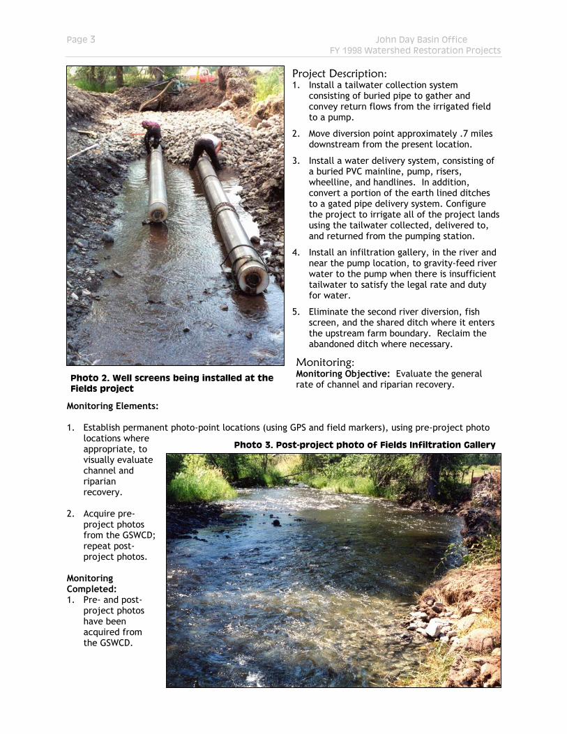
Project Description: 1. Install a tailwater collection system
consisting of buried pipe to gather and convey return flows from the irrigated field to a pump.
2. Move diversion point approximately .7 miles downstream from the present location.
3. Install a water delivery system, consisting of a buried PVC mainline, pump, risers, wheelline, and handlines. In addition, convert a portion of the earth lined ditches to a gated pipe delivery system. Configure the project to irrigate all of the project lands using the tailwater collected, delivered to, and returned from the pumping station.
4. Install an infiltration gallery, in the river and near the pump location, to gravity-feed river water to the pump when there is insufficient tailwater to satisfy the legal rate and duty for water.
5. Eliminate the second river diversion, fish screen, and the shared ditch where it enters the upstream farm boundary. Reclaim the abandoned ditch where necessary.
Monitoring: Monitoring Objective: Evaluate the general rate of channel and riparian recovery.
Photo 2. Well screens being installed at the Fields project
Monitoring Elements: 1. Establish permanent photo-point locations (using GPS and field markers), using pre-project photo
locations where appropriate, to visually evaluate channel and riparian recovery.
Photo 3. Post-project photo of Fields Infiltration Gallery
2. Acquire pre-
project photos from the GSWCD; repeat post-project photos.
Monitoring Completed: 1. Pre- and post-
project photos have been acquired from the GSWCD.
Page 4 John Day Basin Office FY 1998 Watershed Restoration Projects
Project Cost: Local Cost Share 114,075 (69%) BPA Contribution 50,160 (31%) TOTAL $ 164,235
Start Date: July 1997 Completion Date: December 1998
PROJECT: PAGE IRRIGATION CONVERSION
Grantee: Grant Soil and Water Conservation District
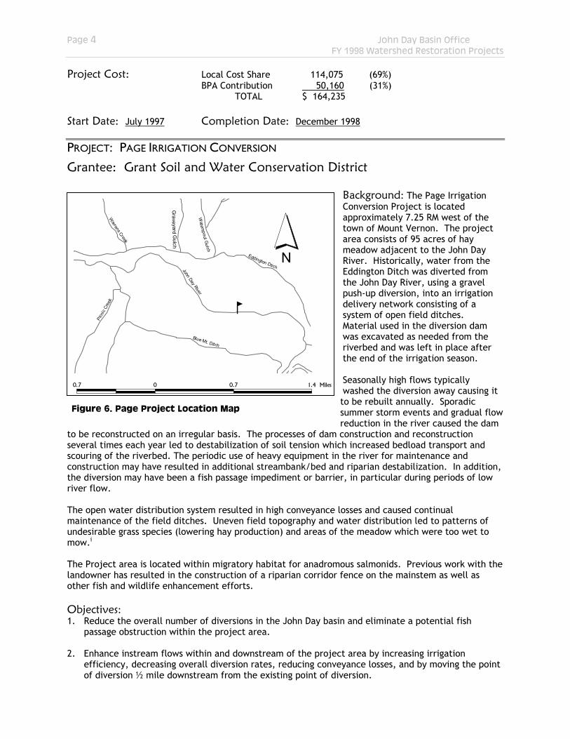
Background: The Page Irrigation Conversion Project is located approximately 7.25 RM west of the town of Mount Vernon. The project area consists of 95 acres of hay meadow adjacent to the John Day River. Historically, water from the Eddington Ditch was diverted from the John Day River, using a gravel push-up diversion, into an irrigation delivery network consisting of a system of open field ditches. Material used in the diversion dam was excavated as needed from the riverbed and was left in place after the end of the irrigation season. Seasonally high flows typically washed the diversion away causing it to be rebuilt annually. Sporadic summer storm events and gradual flow reduction in the river caused the dam
to be reconstructed on an irregular basis. The processes of dam construction and reconstruction several times each year led to destabilization of soil tension which increased bedload transport and scouring of the riverbed. The periodic use of heavy equipment in the river for maintenance and construction may have resulted in additional streambank/bed and riparian destabilization. In addition, the diversion may have been a fish passage impediment or barrier, in particular during periods of low river flow.
b
John Day River
Eddington Dtich
Blue Mt. Ditch
Grave yard G
ulch
Waterspout G
ulch
Warrens Creek
Picn
ic Cr
eek
0.7 0 0.7 1.4 Miles
N
Figure 6. Page Project Location Map
The open water distribution system resulted in high conveyance losses and caused continual maintenance of the field ditches. Uneven field topography and water distribution led to patterns of undesirable grass species (lowering hay production) and areas of the meadow which were too wet to mow.i The Project area is located within migratory habitat for anadromous salmonids. Previous work with the landowner has resulted in the construction of a riparian corridor fence on the mainstem as well as other fish and wildlife enhancement efforts. Objectives: 1. Reduce the overall number of diversions in the John Day basin and eliminate a potential fish
passage obstruction within the project area. 2. Enhance instream flows within and downstream of the project area by increasing irrigation
efficiency, decreasing overall diversion rates, reducing conveyance losses, and by moving the point of diversion ½ mile downstream from the existing point of diversion.
Page 5 John Day Basin Office FY 1998 Watershed Restoration Projects
3. Eliminate direct impacts to riparian areas and streambed/banks (and resulting indirect impacts) associated with the annual and periodic reconstruction of the push-up diversion, thereby enhancing channel stability.
4. Eliminate riverbed scouring and modifications to the hydraulic gradient of the river from the annual
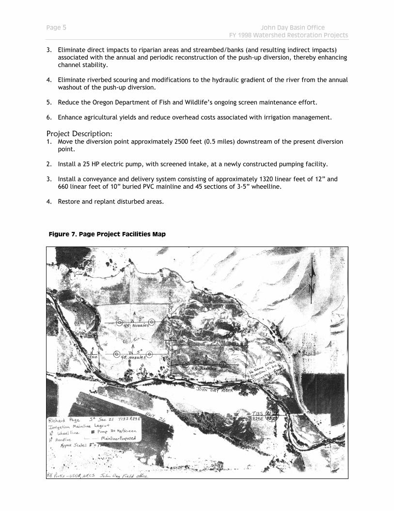
washout of the push-up diversion. 5. Reduce the Oregon Department of Fish and Wildlife’s ongoing screen maintenance effort. 6. Enhance agricultural yields and reduce overhead costs associated with irrigation management. Project Description: 1. Move the diversion point approximately 2500 feet (0.5 miles) downstream of the present diversion
point. 2. Install a 25 HP electric pump, with screened intake, at a newly constructed pumping facility. 3. Install a conveyance and delivery system consisting of approximately 1320 linear feet of 12” and
660 linear feet of 10” buried PVC mainline and 45 sections of 3-5” wheelline. 4. Restore and replant disturbed areas.
Figure 7. Page Project Facilities Map
Page 6 John Day Basin Office FY 1998 Watershed Restoration Projects
Monitoring: Monitoring Objective: Evaluate the rate of channel and riparian recovery. Monitoring Elements: 1. Evaluate channel and riverbank structure, using channel cross sectionsii, along approximately 100
meters of river beginning immediately above the old diversion dam. This assessment will be compared to the original engineering survey (if applicable) to determine extent and rate of channel correction.
2. Establish permanent photo-point locations (using GPS and field markers), using pre-project photo
locations where appropriate, to visually evaluate channel and riparian recovery. 3. Acquire pre-project photos from the GSWCD; repeat post-project photos. Monitoring Completed: 1. Pre- and post-project photos have been taken by the GSWCD. Project Cost: Local Cost Share 107,052 (78%)
BPA Contribution 29,840 (22%) TOTAL $ 136,892
Start Date: April 1997 Completion Date: September 1997
PROJECT: CLAUSEN PUMPING STATION & IRRIGATION UPGRADE
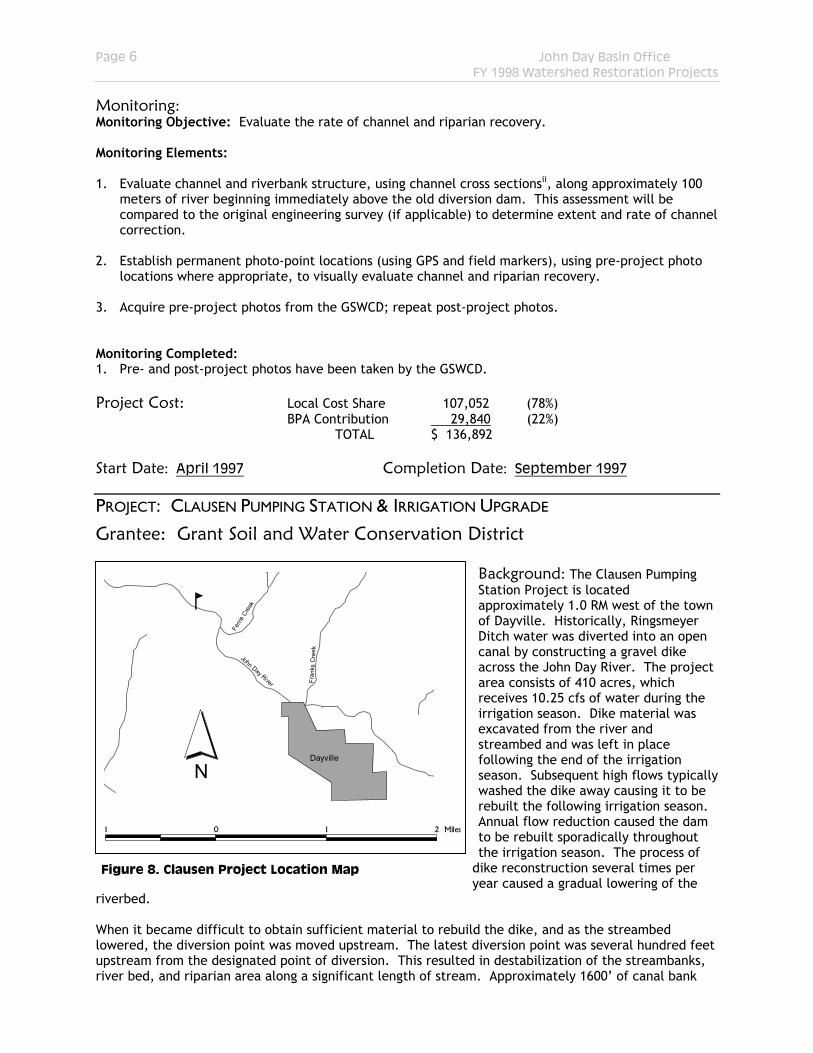
Grantee: Grant Soil and Water Conservation District Background: The Clausen Pumping Station Project is located approximately 1.0 RM west of the town of Dayville. Historically, Ringsmeyer Ditch water was diverted into an open canal by constructing a gravel dike across the John Day River. The project area consists of 410 acres, which receives 10.25 cfs of water during the irrigation season. Dike material was excavated from the river and streambed and was left in place following the end of the irrigation season. Subsequent high flows typically washed the dike away causing it to be rebuilt the following irrigation season. Annual flow reduction caused the dam to be rebuilt sporadically throughout the irrigation season. The process of
dike reconstruction several times per year caused a gradual lowering of the
riverbed.
b
Dayville
Ferri
s Cre
ek
Fra n
k s C
ree k
John Day River
1 0 1 2
N
Miles
Figure 8. Clausen Project Location Map
When it became difficult to obtain sufficient material to rebuild the dike, and as the streambed lowered, the diversion point was moved upstream. The latest diversion point was several hundred feet upstream from the designated point of diversion. This resulted in destabilization of the streambanks, river bed, and riparian area along a significant length of stream. Approximately 1600’ of canal bank
Page 7 John Day Basin Office FY 1998 Watershed Restoration Projects
was reconstructed using streambed gravel and much of the streambank was rebuilt several times each year. An open ditch carried the diverted flows approximately 3400’ to the irrigated lands. The open canal led to high conveyance losses and continual maintenance of the ditch. The project area is within migratory habitat for anadromous fish. Objectives: 1. Reduce the overall number of diversions in the John Day basin and eliminate a potential fish
passage obstruction within the project area. 2. Enhance instream flows within and downstream of the project area by increasing irrigation
efficiency, decreasing overall diversion rates, reducing conveyance losses, and by moving the point of diversion 3200 feet (.6 miles) downstream from the existing point of diversion.
3. Eliminate direct impacts to riparian areas and streambed/banks (and resulting indirect impacts)
associated with the annual and periodic reconstruction of the push-up diversion, thereby enhancing channel stability.
4. Eliminate riverbed scouring and modifications to the hydraulic gradient of the river from the annual
washout of the push-up diversion. 5. Reduce the Oregon Department of Fish and Wildlife’s ongoing screen maintenance effort. 6. Enhance agricultural yields and reduce overhead costs associated with irrigation management. Project Description:
1. Move the point of diversion for the Ringsmeyer ditch approximately 3200 feet downstream. 2. Modify the diversion method from a dam to an electric pump, with facilities. Install a screened
pump intake to prevent fish entrainment. 3. Convert the open canal to a buried pipe conveyance system. Install approximately 320 linear feet
of 18”, 700 linear feet of 4”, and 365 linear feet of 3” buried PVC conveyance pipe with a stilling basin.
Monitoring: Monitoring Objective: Evaluate the rate of channel and riparian recovery. Monitoring Elements: 1. Evaluate channel and riverbank structure, using channel cross sections, along approximately 100
meters of river beginning immediately above the old diversion dam. This assessment will be compared to the original engineering survey (if applicable) to determine extent and rate of channel correction.
2. Photo 3. Post-project photo of Fields Infiltration Gallery 3. Establish permanent photo-point locations (using GPS and field markers), using pre-project photo
locations where appropriate, to visually evaluate channel and riparian recovery. 4. Acquire pre-project photos from the GSWCD; repeat post-project photos. Monitoring Completed: 1. Pre- and post-project photos have been acquired from the GSWCD. Project Cost: Local Cost Share 96,572 (83%)
BPA Contribution 20,000 (17%)
Page 8 John Day Basin Office FY 1998 Watershed Restoration Projects
TOTAL $ 116,572 Start Date: April 1997 Completion Date: September 1998
PROJECT: ENTERPRISE DIVERSION
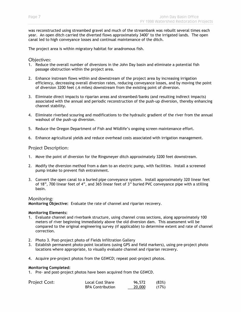
Grantee: Grant Soil and Water Conservation District Background: Currently, Enterprise ditch water is diverted into an open canal by constructing a gravel dike across the John Day River. The temporary gravel berm is reconstructed annually, and as required during the irrigation season, as river flows decline. Depending upon river flow condition, the diversion can become a partial to total barrier to migrating fish. Dike Material is excavated from the riverbed and the dike is left in place following the end of the
irrigation season. Subsequent high flows typically wash the dike
away causing it to be rebuilt the following irrigation season. The process of dike reconstruction, often several times per year causes a gradual lowering of the riverbed. This method of diversion practice requires periodic use of heavy equipment in the river to perform maintenance.
b John DayJohn Day River
Luce
Cre
e k
Ca n
yon
Cr
Dav
is Cr
Qua
rtz G
ulch
2 0 2
N
4 Miles
Figure 9. Enterprise Project Location Map
The chronic effects of construction and reconstruction of this type of diversion result in apparent destabilization of the stream bed and banks, which prohibits the establishment of riparian vegetation. This project is located within the anadromous migratory corridor and known overwintering/migratory habitat for bull trout, westslope cutthroat, and redband trout. The project area also likely provides late spring/early summer rearing habitat for juvenile anadromous species. Objectives: 1. Reduce the overall number of diversions in the John Day basin and eliminate a potential fish
passage obstruction within the project area. 2. Eliminate direct impacts to riparian areas and streambed/banks (and resulting indirect impacts)
associated with the annual and periodic reconstruction of the push-up diversion, thereby enhancing channel stability.
3. Eliminate riverbed scouring and modifications to the hydraulic gradient of the river from the annual
washout of the push-up diversions. 4. Reduce overhead costs associated with irrigation management.
Page 9 John Day Basin Office FY 1998 Watershed Restoration Projects
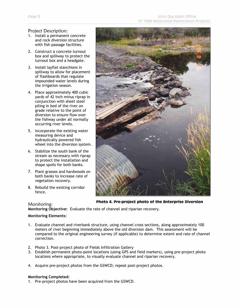
Project Description: 1. Install a permanent concrete
and rock diversion structure with fish passage facilities.
2. Construct a concrete turnout box and spillway to protect the turnout box and a headgate.
3. Install layflat stanchions in spillway to allow for placement of flashboards that regulate impounded water levels during the irrigation season.
4. Place approximately 400 cubic yards of 42 inch minus riprap in conjunction with sheet steel piling in bed of the river on grade relative to the point of diversion to ensure flow over the fishway under all normally occurring river levels.
5. Incorporate the existing water measuring device and hydraulically powered fish wheel into the diversion system.
6. Stabilize the south bank of the stream as necessary with riprap to protect the installation and shape spoils for both banks.
7. Plant grasses and hardwoods on both banks to increase rate of vegetation recovery.
8. Rebuild the existing corridor fence.
Monitoring: Monitoring Objective: Evaluate the rate of channel and riparian recovery.
Photo 4. Pre-project photo of the Enterprise Diversion
Monitoring Elements: 1. Evaluate channel and riverbank structure, using channel cross sections, along approximately 100
meters of river beginning immediately above the old diversion dam. This assessment will be compared to the original engineering survey (if applicable) to determine extent and rate of channel correction.
2. Photo 3. Post-project photo of Fields Infiltration Gallery 3. Establish permanent photo-point locations (using GPS and field markers), using pre-project photo
locations where appropriate, to visually evaluate channel and riparian recovery. 4. Acquire pre-project photos from the GSWCD; repeat post-project photos.
Monitoring Completed: 1. Pre-project photos have been acquired from the GSWCD.
Page 10 John Day Basin Office FY 1998 Watershed Restoration Projects
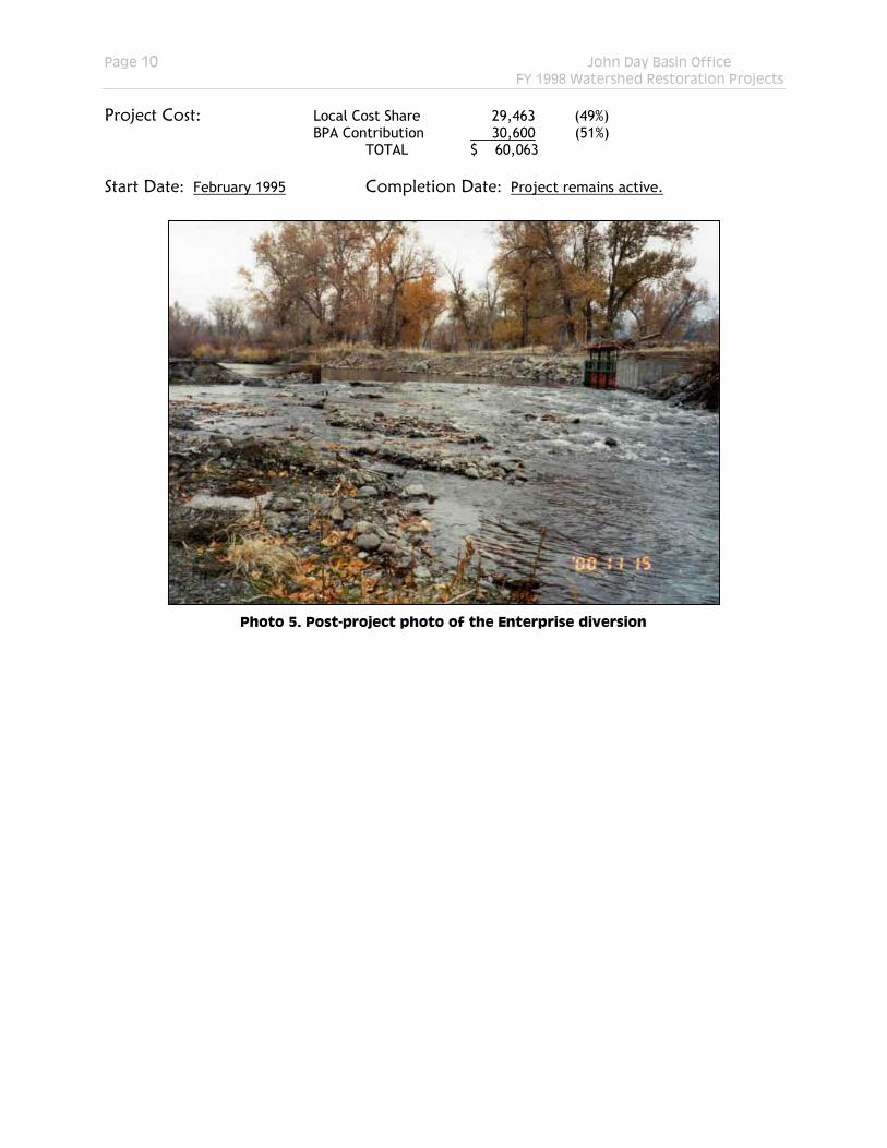
Project Cost: Local Cost Share 29,463 (49%) BPA Contribution 30,600 (51%) TOTAL $ 60,063
Start Date: February 1995 Completion Date: Project remains active.
Photo 5. Post-project photo of the Enterprise diversion
Page 11 John Day Basin Office FY 1998 Watershed Restoration Projects
PROJECT: LEE IRRIGATION CONVERSION
Grantee: Grant Soil and Water Conservation District
b
Dam
on Creek
John
Day
Rive
r
Clark Creek
Mc Cle lla n
Cr eek
Ril e
y C
r ee k
0.6 0 0.6 1.2 Miles
N
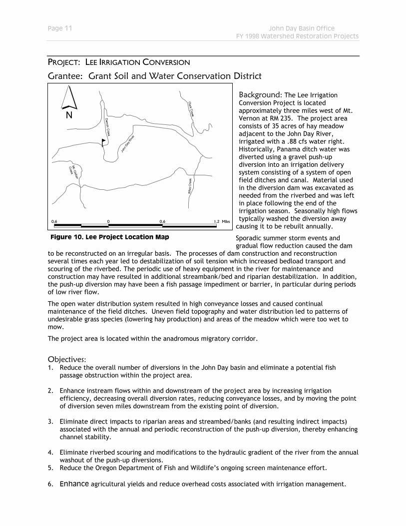
Background: The Lee Irrigation Conversion Project is located approximately three miles west of Mt. Vernon at RM 235. The project area consists of 35 acres of hay meadow adjacent to the John Day River, irrigated with a .88 cfs water right. Historically, Panama ditch water was diverted using a gravel push-up diversion into an irrigation delivery system consisting of a system of open field ditches and canal. Material used in the diversion dam was excavated as needed from the riverbed and was left in place following the end of the irrigation season. Seasonally high flows typically washed the diversion away
causing it to be rebuilt annually.
Sporadic summer storm events and gradual flow reduction caused the dam
to be reconstructed on an irregular basis. The processes of dam construction and reconstruction several times each year led to destabilization of soil tension which increased bedload transport and scouring of the riverbed. The periodic use of heavy equipment in the river for maintenance and construction may have resulted in additional streambank/bed and riparian destabilization. In addition, the push-up diversion may have been a fish passage impediment or barrier, in particular during periods of low river flow.
Figure 10. Lee Project Location Map
The open water distribution system resulted in high conveyance losses and caused continual maintenance of the field ditches. Uneven field topography and water distribution led to patterns of undesirable grass species (lowering hay production) and areas of the meadow which were too wet to mow.
The project area is located within the anadromous migratory corridor.
Objectives: 1. Reduce the overall number of diversions in the John Day basin and eliminate a potential fish
passage obstruction within the project area. 2. Enhance instream flows within and downstream of the project area by increasing irrigation
efficiency, decreasing overall diversion rates, reducing conveyance losses, and by moving the point of diversion seven miles downstream from the existing point of diversion.
3. Eliminate direct impacts to riparian areas and streambed/banks (and resulting indirect impacts)
associated with the annual and periodic reconstruction of the push-up diversion, thereby enhancing channel stability.
4. Eliminate riverbed scouring and modifications to the hydraulic gradient of the river from the annual
washout of the push-up diversions. 5. Reduce the Oregon Department of Fish and Wildlife’s ongoing screen maintenance effort. 6. Enhance agricultural yields and reduce overhead costs associated with irrigation management.
Page 12 John Day Basin Office FY 1998 Watershed Restoration Projects
Project Description: 1. Move the diversion point approximately seven miles downstream of the present diversion point. 2. Install a 15 HP electric pump, with screened intake, at the new pumping facility (pump pad,
electric panel, etc). 3. Install a system of buried mainlines using 3700 feet of 3-4 inch high-pressure PVC pipe with riser
outlets every 50-60 feet. 4. Assemble one 4” wheeline with mover and three 3” hand lines. Monitoring: Monitoring Objective: Determine overall water use in the new irrigation system. Monitoring Elements: 1. Determine whether landowner is monitoring irrigation rates and whether pre-project data exists. 2. Photo 3. Post-project photo of Fields Infiltration Gallery 3. Establish permanent photo-point locations (using GPS and field markers), using pre-project photo
locations where appropriate, to visually evaluate channel and riparian recovery. 4. Acquire pre-project photos from the GSWCD; repeat post-project photos. Monitoring Completed: 1. Pre- and post-project photos have been acquired from the GSWCD. Project Cost: Local Cost Share 31,027 (45%)
BPA Contribution 37,740 (55%) TOTAL $ 68,767 Start Date: September 1998 Completion Date: April 1999
Page 13 John Day Basin Office FY 1998 Watershed Restoration Projects
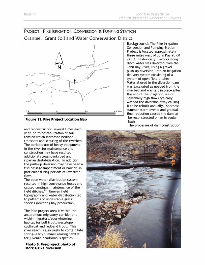
PROJECT: PIKE IRRIGATION CONVERSION & PUMPING STATION
Grantee: Grant Soil and Water Conservation District Background: The Pike Irrigation Conversion and Pumping Station Project is located approximately three miles west of John Day at RM 245.3. Historically, Laycock-Long ditch water was diverted from the John Day River, using a gravel push-up diversion, into an irrigation delivery system consisting of a system of open field ditches. Material used in the diversion dam was excavated as needed from the riverbed and was left in place after the end of the irrigation season. Seasonally high flows typically washed the diversion away causing it to be rebuilt annually. Sporadic summer storm events and gradual flow reduction caused the dam to be reconstructed on an irregular basis.
bJo
hn D
ay R
iver
Laycock-Long Ditch
Panama Ditch
0.8 0 0.8
N
1.6 Miles
The processes of dam construction and reconstruction several times each year led to destabilization of soil tension which increased bedload transport and scouring of the riverbed. The periodic use of heavy equipment in the river for maintenance and construction may have resulted in additional streambank/bed and riparian destabilization. In addition, the push-up diversion may have been a fish passage impediment or barrier, in particular during periods of low river flow.
Figure 11. Pike Project Location Map
The open water distribution system resulted in high conveyance losses and caused continual maintenance of the field ditches.iii Uneven field topography and water distribution led to patterns of undesirable grass species (lowering hay production. The Pike project area is within the anadromous migratory corridor and within migratory/overwintering habitat for bull trout, westslope cutthroat and redband trout. This river reach is also likely to contain late spring—early summer rearing habitat for juvenile anadromous species.
Photo 6. Pre-project photo of Morris/Pike Diversion
Page 14 John Day Basin Office FY 1998 Watershed Restoration Projects
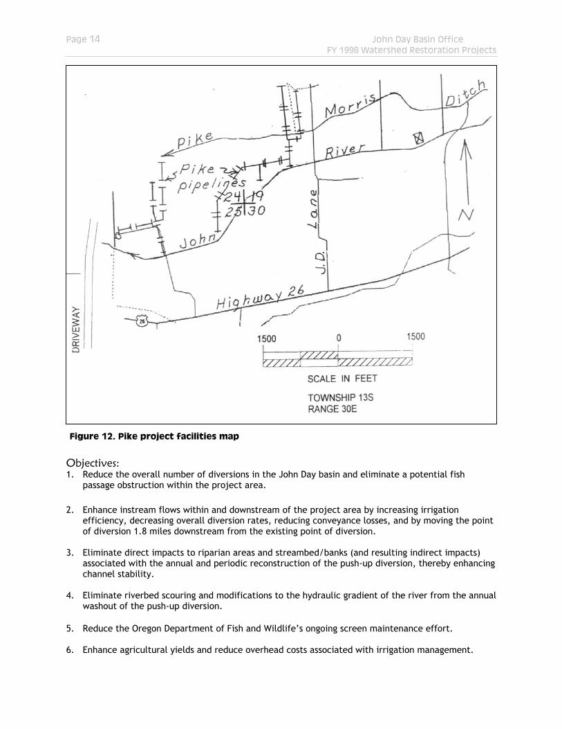
Objectives:
Figure 12. Pike project facilities map
1. Reduce the overall number of diversions in the John Day basin and eliminate a potential fish passage obstruction within the project area.
2. Enhance instream flows within and downstream of the project area by increasing irrigation
efficiency, decreasing overall diversion rates, reducing conveyance losses, and by moving the point of diversion 1.8 miles downstream from the existing point of diversion.
3. Eliminate direct impacts to riparian areas and streambed/banks (and resulting indirect impacts)
associated with the annual and periodic reconstruction of the push-up diversion, thereby enhancing channel stability.
4. Eliminate riverbed scouring and modifications to the hydraulic gradient of the river from the annual
washout of the push-up diversion. 5. Reduce the Oregon Department of Fish and Wildlife’s ongoing screen maintenance effort. 6. Enhance agricultural yields and reduce overhead costs associated with irrigation management.
Page 15 John Day Basin Office FY 1998 Watershed Restoration Projects
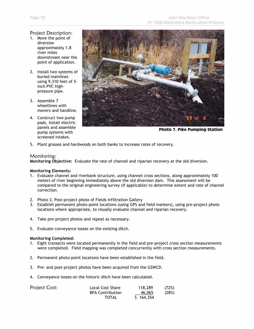
Project Description:
Photo 7. Pike Pumping Station
1. Move the point of diversion approximately 1.8 river miles downstream near the point of application.
2. Install two systems of
buried mainlines using 9,310 feet of 5-inch PVC high-pressure pipe.
3. Assemble 7
wheellines with movers and handline.
4. Construct two pump pads, install electric panels and assemble pump systems with screened intakes.
5. Plant grasses and hardwoods on both banks to increase rates of recovery. Monitoring: Monitoring Objective: Evaluate the rate of channel and riparian recovery at the old diversion. Monitoring Elements: 1. Evaluate channel and riverbank structure, using channel cross sections, along approximately 100
meters of river beginning immediately above the old diversion dam. This assessment will be compared to the original engineering survey (if applicable) to determine extent and rate of channel correction.
2. Photo 3. Post-project photo of Fields Infiltration Gallery 3. Establish permanent photo-point locations (using GPS and field markers), using pre-project photo
locations where appropriate, to visually evaluate channel and riparian recovery. 4. Take pre-project photos and repeat as necessary. 5. Evaluate conveyance losses on the existing ditch. Monitoring Completed: 1. Eight transects were located permanently in the field and pre-project cross section measurements
were completed. Field mapping was completed concurrently with cross section measurements. 2. Permanent photo-point locations have been established in the field. 3. Pre- and post-project photos have been acquired from the GSWCD. 4. Conveyance losses on the historic ditch have been calculated. Project Cost: Local Cost Share 118,289 (72%)
BPA Contribution 46,065 (28%) TOTAL $ 164,354
Page 16 John Day Basin Office FY 1998 Watershed Restoration Projects
Start Date: April 1995 Completion Date: May 2000
PROJECT: MORRIS IRRIGATION CONVERSION & PUMPING STATION
Grantee: Grant Soil and Water Conservation District Background: The Morris Irrigation Conversion and Pumping Station Project is located approximately three miles west of John Day at RM 244.
bJohn Day River
Qua rtz G
u lc h
Laycock-Long Ditch
0.5 0 0.5 1 Miles
N The Morris Project historically used the same diversion structure as in the Pike Project. For a complete discussion of this diversion, see the description of the Pike Project above. Conveyance losses to the upstream boundary of the Morris property were also significant.iv Objectives: Covered under the Pike Project description. Project Description:
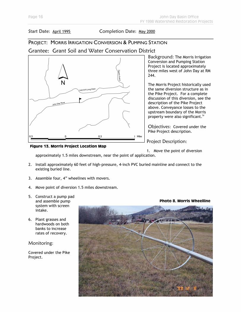
1. Move the point of diversion
approximately 1.5 miles downstream, near the point of application.
Figure 13. Morris Project Location Map
2. Install approximately 60 feet of high-pressure, 4-inch PVC buried mainline and connect to the
existing buried line. 3. Assemble four, 4” wheelines with movers. 4. Move point of diversion 1.5 miles downstream. 5. Construct a pump pad
and assemble pump system with screen intake.
Photo 8. Morris Wheelline
6. Plant grasses and
hardwoods on both banks to increase rates of recovery.
Monitoring: Covered under the Pike Project.
Page 17 John Day Basin Office FY 1998 Watershed Restoration Projects
Project Cost: Local Cost Share 34,525 (52%)
BPA Contribution 31,781 (48%) TOTAL $ 66,306
Start Date: April 1995 Completion Date: December 1999
PROJECT: CROWN RANCH DIVERSION
Grantee: Grant Soil and Water Conservation District Background: The Crown Ranch Diversion Project is located approximately five miles east of John Day at RM 253.5. Historically, irrigation water was diverted into an open canal by constructing a gravel dike across the John Day River. The project area consists of 115 acres, which receives 2.78 cfs during the irrigation season.
Dike material was excavated from the river and streambeds and the dam was left in place following the end of the irrigation season. Subsequent high flows typically washed the dike away causing it to be rebuilt the following irrigation season. Annual flow reduction caused the dam to be rebuilt
sporadically throughout the irrigation season. The process of dike
reconstruction several times per year caused a gradual lowering of the riverbed. When it became difficult to obtain sufficient material to rebuild the dike, and as the streambed lowered, the diversion point was moved upstream. The latest diversion point was several hundred feet or more upstream from the designated point of diversion. This resulted in destabilization of the streambanks, river bed, and riparian area along a significant length of stream.
b
John Day River Disse l C
reek
Dean Creek
Grub Creek
0.6 0 0.6 1.2 Miles
N
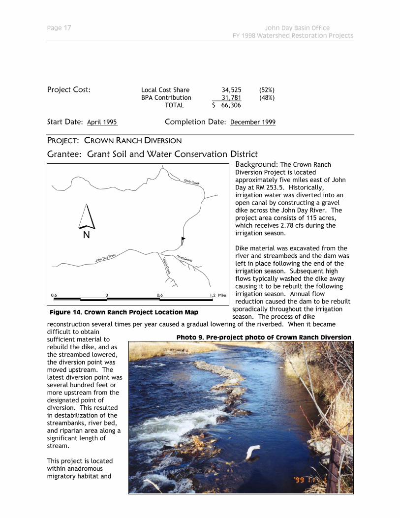
Figure 14. Crown Ranch Project Location Map
Photo 9. Pre-project photo of Crown Ranch Diversion
This project is located within anadromous migratory habitat and

Page 18 John Day Basin Office FY 1998 Watershed Restoration Projects
may include limited spawning areas for spring chinook. In addition, this river reach contains known migratory—overwintering habitat for bull trout, westslope cutthroat, and redband trout. It also likely provides late spring—early summer juvenile rearing habitat for anadromous species. Objectives: 1. Reduce the overall number of diversions in the John Day basin and eliminate a potential fish
passage obstruction within the project area. 2. Eliminate direct impacts to riparian areas and streambed/banks (and resulting indirect impacts)
associated with the annual and periodic reconstruction of the push-up diversion, thereby enhancing channel stability.
3. Eliminate riverbed scouring and modifications to the hydraulic gradient of the river from the annual
washout of the push-up diversion. 4. Reduce overhead costs associated with irrigation management. Project Description: 1. Install a permanent concrete and rock diversion structure at the existing ditch head, which is the
legal point of diversion. 2. Construct a concrete turnout box and spillway, incorporating a trash screen to protect the turnout
box, a headgate for water regulation and a water-measuring weir as appropriate. 3. Install layflat stanchions in spillway to allow for placement of flashboards that regulate impounded
water level during the irrigation season. 4. Place approximately 200 cubic yards of 36 inch minus riprap in conjunction with sheet steel piling
in the bed of the river on grade relative to point of diversion to ensure flow over the fishway under all normally occurring river levels.
5. Incorporate the existing hydraulically powered fish wheel into the diversion system. 6. Stabilize the east and west banks of the stream as necessary with riprap to protect the installation
and shape spoils on both banks. 7. Plant grasses and hardwoods on both banks to increase rates of recovery Monitoring: Monitoring Objective: Evaluate the rate of channel and riparian recovery at the old diversion. Monitoring Elements: 1. Evaluate channel and riverbank structure, using channel cross sections, along approximately 100
meters of river beginning immediately above the old diversion dam. This assessment will be compared to the original engineering survey (if applicable) to determine extent and rate of channel correction.
2. Photo 3. Post-project photo of Fields Infiltration Gallery 3. Establish permanent photo-point locations (using GPS and field markers), using pre-project photo
locations where appropriate, to visually evaluate channel and riparian recovery. 4. Acquire pre-project photos from the GSWCD; repeat post-project photos. Monitoring Completed: 1. Eight transects were located permanently in the field and pre-project cross section measurements
were completed. Field mapping was completed concurrently with cross section measurements.

Page 19 John Day Basin Office FY 1998 Watershed Restoration Projects
3. Permanent photo-point locations have been established in the field. 4. Pre- and post-project photos have been acquired from the GSWCD. Project Cost: Local Cost Share 24,197 (53%)
BPA Contribution 21,085 (47%) TOTAL $ 45,282 Start Date: July 1997 Completion Date: Project is active.
PROJECT: HOLMES PIPELINE
Grantee: Grant Soil and Water Conservation District Background: The Holmes Pipeline Project is located approximately 3.0 miles east of Galena at RM 48.5 of the Middle Fork John Day River. Historically, irrigation water was diverted into an open canal by constructing a gravel dike across the Middle Fork. The project area consists of 91 acres, which receives 2.27 cfs during the irrigation season. Dike material was excavated from the river and streambeds and the dam was left in place following the end of the irrigation season. Subsequent high flows typically washed the dike away causing it to be rebuilt the following irrigation season. Annual flow reduction caused the dam to be rebuilt sporadically throughout the irrigation season. The process of dike reconstruction several
b
Middle Fork John Day River
Cam
p Cr
eek
1 0 1 2
N
Miles
Figure 15. Holmes Project Location Map Photo 10. Pre-project photo of Holmes Diversion
Page 20 John Day Basin Office FY 1998 Watershed Restoration Projects
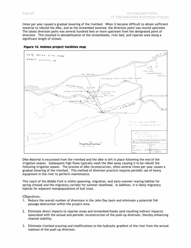
times per year caused a gradual lowering of the riverbed. When it became difficult to obtain sufficient material to rebuild the dike, and as the streambed lowered, the diversion point was moved upstream. The latest diversion point was several hundred feet or more upstream from the designated point of diversion. This resulted in destabilization of the streambanks, river bed, and riparian area along a significant length of stream. Figure 16. Holmes project facilities map
Dike Material is excavated from the riverbed and the dike is left in place following the end of the irrigation season. Subsequent high flows typically wash the dike away causing it to be rebuilt the following irrigation season. The process of dike reconstruction, often several times per year causes a gradual lowering of the riverbed. This method of diversion practice requires periodic use of heavy equipment in the river to perform maintenance. This reach of the Middle Fork is within spawning, migration, and early summer rearing habitat for spring chinook and the migratory corridor for summer steelhead. In addition, it is likely migratory habitat for adjacent metapopulations of bull trout. Objectives: 1. Reduce the overall number of diversions in the John Day basin and eliminate a potential fish
passage obstruction within the project area. 2. Eliminate direct impacts to riparian areas and streambed/banks (and resulting indirect impacts)
associated with the annual and periodic reconstruction of the push-up diversion, thereby enhancing channel stability.
3. Eliminate riverbed scouring and modifications to the hydraulic gradient of the river from the annual
washout of the push-up diversion.
Page 21 John Day Basin Office FY 1998 Watershed Restoration Projects
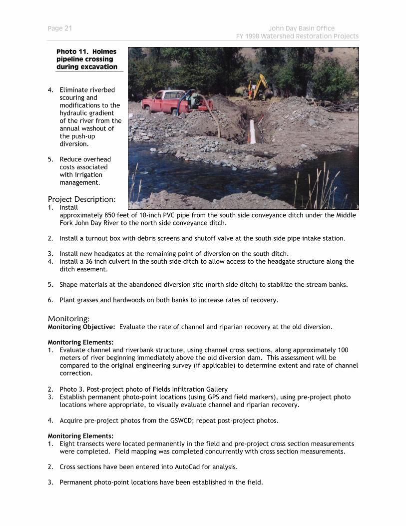
Photo 11. Holmes pipeline crossing during excavation
4. Eliminate riverbed
scouring and modifications to the hydraulic gradient of the river from the annual washout of the push-up diversion.
5. Reduce overhead
costs associated with irrigation management.
Project Description: 1. Install
approximately 850 feet of 10-inch PVC pipe from the south side conveyance ditch under the Middle Fork John Day River to the north side conveyance ditch.
2. Install a turnout box with debris screens and shutoff valve at the south side pipe intake station. 3. Install new headgates at the remaining point of diversion on the south ditch. 4. Install a 36 inch culvert in the south side ditch to allow access to the headgate structure along the
ditch easement. 5. Shape materials at the abandoned diversion site (north side ditch) to stabilize the stream banks. 6. Plant grasses and hardwoods on both banks to increase rates of recovery. Monitoring: Monitoring Objective: Evaluate the rate of channel and riparian recovery at the old diversion. Monitoring Elements: 1. Evaluate channel and riverbank structure, using channel cross sections, along approximately 100
meters of river beginning immediately above the old diversion dam. This assessment will be compared to the original engineering survey (if applicable) to determine extent and rate of channel correction.
2. Photo 3. Post-project photo of Fields Infiltration Gallery 3. Establish permanent photo-point locations (using GPS and field markers), using pre-project photo
locations where appropriate, to visually evaluate channel and riparian recovery. 4. Acquire pre-project photos from the GSWCD; repeat post-project photos. Monitoring Elements: 1. Eight transects were located permanently in the field and pre-project cross section measurements
were completed. Field mapping was completed concurrently with cross section measurements. 2. Cross sections have been entered into AutoCad for analysis. 3. Permanent photo-point locations have been established in the field.
Page 22 John Day Basin Office FY 1998 Watershed Restoration Projects
4. Pre- and post-project photos have been acquired from the GSWCD. Project Cost: Local Cost Share 21,511 (54%)
BPA Contribution 18,535 (46%) TOTAL $ 40,046 Start Date: June 1998 Completion Date: October 1998
PROJECT: RUDISHAUSER INFILTRATION GALLERY
Grantee: Grant Soil and Water Conservation District Background: The Rudishauser Infiltration Gallery Project is located approximately 5.0 miles west of the town of Prairie City. The project area consists of 75 acres of hay meadow adjacent to the John Day River. Historically, water from the Rudishauser Ditch was diverted from Indian Creek, using a gravel push-up diversion, into an irrigation delivery network consisting of a system of open field ditches. Material used in the diversion dam was excavated as needed from the riverbed and was left in place after the end of the irrigation season.
Seasonally high flows typically washed the diversion away causing it to be rebuilt annually. Sporadic summer storm
events and gradual flow reduction in the river caused the dam to be reconstructed
on an irregular basis. The processes of dam construction and reconstruction several times each year led to destabilization of soil tension which increased bedload transport and scouring of the riverbed. The periodic use of heavy equipment in the river for maintenance and construction may have resulted in additional streambank/bed and riparian destabilization. In addition, the diversion may have been a fish passage impediment or barrier, in particular during periods of low river flow.
b
Castle
Creek
Bea
r Cre
e k
John Day River
Fisk Creek
P ine
Cre
ek
Ind ian Creek
0.9 0 0.9
N
1.8 Miles
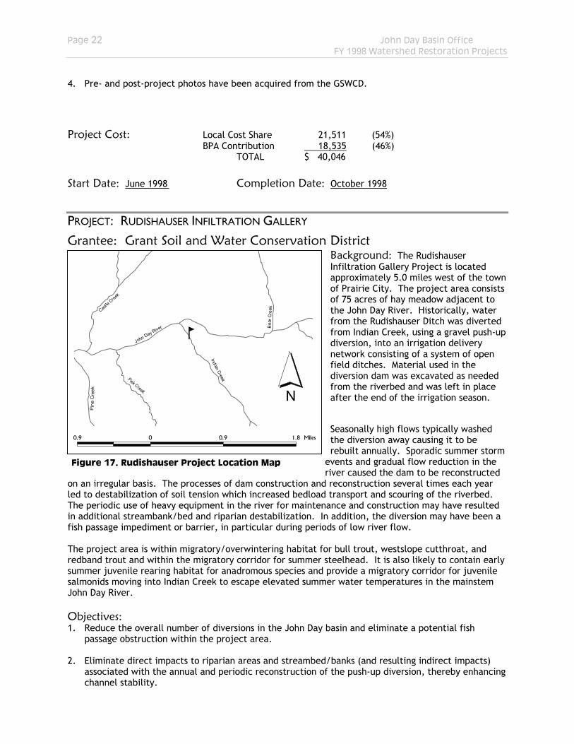
Figure 17. Rudishauser Project Location Map
The project area is within migratory/overwintering habitat for bull trout, westslope cutthroat, and redband trout and within the migratory corridor for summer steelhead. It is also likely to contain early summer juvenile rearing habitat for anadromous species and provide a migratory corridor for juvenile salmonids moving into Indian Creek to escape elevated summer water temperatures in the mainstem John Day River. Objectives: 1. Reduce the overall number of diversions in the John Day basin and eliminate a potential fish
passage obstruction within the project area. 2. Eliminate direct impacts to riparian areas and streambed/banks (and resulting indirect impacts)
associated with the annual and periodic reconstruction of the push-up diversion, thereby enhancing channel stability.
Page 23 John Day Basin Office FY 1998 Watershed Restoration Projects
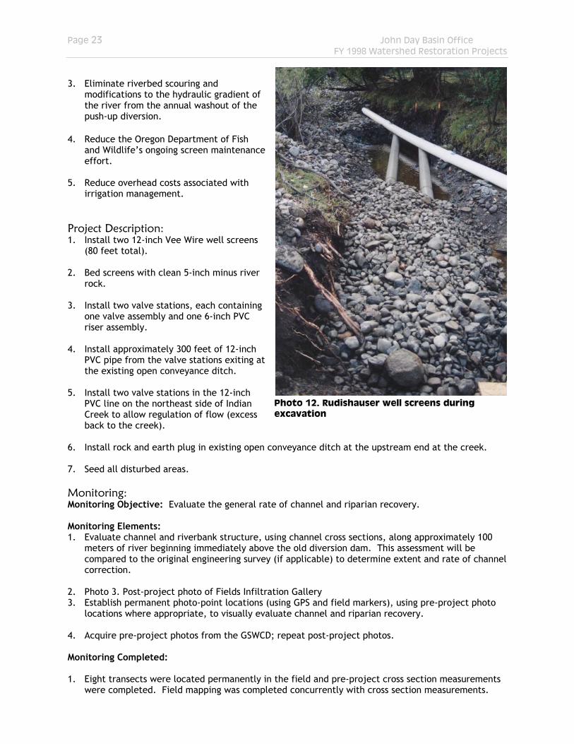
Photo 12. Rudishauser well screens during excavation
3. Eliminate riverbed scouring and modifications to the hydraulic gradient of the river from the annual washout of the push-up diversion.
4. Reduce the Oregon Department of Fish
and Wildlife’s ongoing screen maintenance effort.
5. Reduce overhead costs associated with
irrigation management. Project Description: 1. Install two 12-inch Vee Wire well screens
(80 feet total). 2. Bed screens with clean 5-inch minus river
rock. 3. Install two valve stations, each containing
one valve assembly and one 6-inch PVC riser assembly.
4. Install approximately 300 feet of 12-inch
PVC pipe from the valve stations exiting at the existing open conveyance ditch.
5. Install two valve stations in the 12-inch
PVC line on the northeast side of Indian Creek to allow regulation of flow (excess back to the creek).
6. Install rock and earth plug in existing open conveyance ditch at the upstream end at the creek. 7. Seed all disturbed areas. Monitoring: Monitoring Objective: Evaluate the general rate of channel and riparian recovery. Monitoring Elements: 1. Evaluate channel and riverbank structure, using channel cross sections, along approximately 100
meters of river beginning immediately above the old diversion dam. This assessment will be compared to the original engineering survey (if applicable) to determine extent and rate of channel correction.
2. Photo 3. Post-project photo of Fields Infiltration Gallery 3. Establish permanent photo-point locations (using GPS and field markers), using pre-project photo
locations where appropriate, to visually evaluate channel and riparian recovery. 4. Acquire pre-project photos from the GSWCD; repeat post-project photos. Monitoring Completed: 1. Eight transects were located permanently in the field and pre-project cross section measurements
were completed. Field mapping was completed concurrently with cross section measurements.
Page 24 John Day Basin Office FY 1998 Watershed Restoration Projects
3. Permanent photo-point locations have been established in the field. 4. Pre- and post-project photos have been acquired from the GSWCD. Project Cost: Local Cost Share 14,464 (50%)
BPA Contribution 14,523 (50%) TOTAL $ 28,987 Start Date: July 1998 Completion Date: August 1998
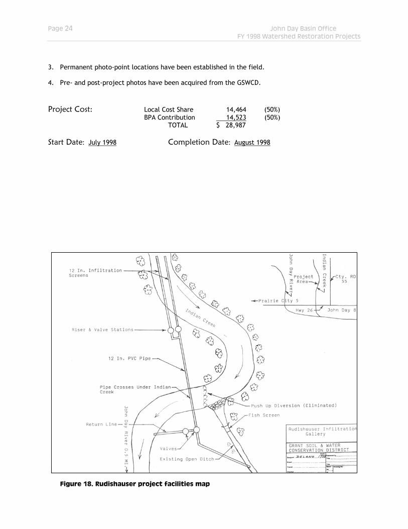
Figure 18. Rudishauser project facilities map
Page 25 John Day Basin Office FY 1998 Watershed Restoration Projects
Attachment 1
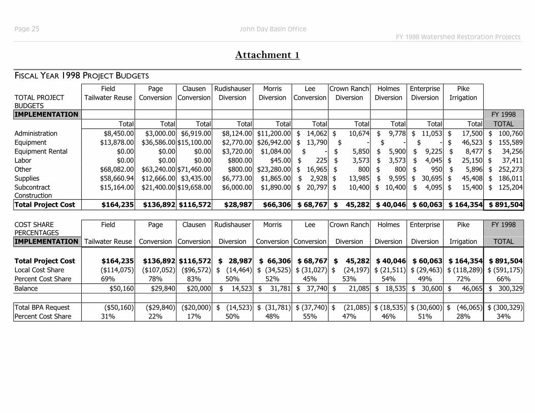
FISCAL YEAR 1998 PROJECT BUDGETS
Field Page Clausen Rudishauser Morris Lee Crown Ranch Holmes Enterprise PikeTOTAL PROJECT BUDGETS
Tailwater Reuse Conversion Conversion Diversion Diversion Conversion Diversion Diversion Diversion Irrigation
IMPLEMENTATION FY 1998 Total Total Total Total Total Total Total Total Total Total TOTAL
Administration $8,450.00 $3,000.00 $6,919.00 $8,124.00 $11,200.00 $ 14,062 $ 10,674 $ 9,778 $ 11,053 $ 17,500 $ 100,760 Equipment $13,878.00 $36,586.00 $15,100.00 $2,770.00 $26,942.00 $ 13,790 $ - $ - $ - $ 46,523 $ 155,589 Equipment Rental $0.00 $0.00 $0.00 $3,720.00 $1,084.00 $ - $ 5,850 $ 5,900 $ 9,225 $ 8,477 $ 34,256 Labor $0.00 $0.00 $0.00 $800.00 $45.00 $ 225 $ 3,573 $ 3,573 $ 4,045 $ 25,150 $ 37,411 Other $68,082.00 $63,240.00 $71,460.00 $800.00 $23,280.00 $ 16,965 $ 800 $ 800 $ 950 $ 5,896 $ 252,273 Supplies $58,660.94 $12,666.00 $3,435.00 $6,773.00 $1,865.00 $ 2,928 $ 13,985 $ 9,595 $ 30,695 $ 45,408 $ 186,011 Subcontract Construction
$15,164.00 $21,400.00 $19,658.00 $6,000.00 $1,890.00 $ 20,797 $ 10,400 $ 10,400 $ 4,095 $ 15,400 $ 125,204
Total Project Cost $164,235 $136,892 $116,572 $28,987 $66,306 $ 68,767 $ 45,282 $ 40,046 $ 60,063 $ 164,354 $ 891,504
COST SHARE PERCENTAGES
Field Page Clausen Rudishauser Morris Lee Crown Ranch Holmes Enterprise Pike FY 1998
IMPLEMENTATION Tailwater Reuse Conversion Conversion Diversion Conversion Conversion Diversion Diversion Diversion Irrigation TOTAL
Total Project Cost $164,235 $136,892 $116,572 $ 28,987 $ 66,306 $ 68,767 $ 45,282 $ 40,046 $ 60,063 $ 164,354 $ 891,504 Local Cost Share ($114,075) ($107,052) ($96,572) $ (14,464) $ (34,525) $ (31,027) $ (24,197) $ (21,511) $ (29,463) $ (118,289) $ (591,175) Percent Cost Share 69% 78% 83% 50% 52% 45% 53% 54% 49% 72% 66% Balance $50,160 $29,840 $20,000 $ 14,523 $ 31,781 $ 37,740 $ 21,085 $ 18,535 $ 30,600 $ 46,065 $ 300,329
Total BPA Request ($50,160) ($29,840) ($20,000) $ (14,523) $ (31,781) $ (37,740) $ (21,085) $ (18,535) $ (30,600) $ (46,065) $ (300,329) Percent Cost Share 31% 22% 17% 50% 48% 55% 47% 46% 51% 28% 34%

Page 26 John Day Basin Office FY 1998 Watershed Restoration Projects
ENDNOTES i Personal communication with Richard Page (10/20/99). ii Harrelson C.C., C.L. Rawlins, and J.P. Potyondy. 1994. Stream channel reference sites: an illustrated guide to field technique. USDA Forest Service, Gen. Tech. Rpt. RM-245. iii Ditch losses from the point of diversion to the upper boundary of the project area have been estimated at 73.3% or 1.84 cfs (S. Robertson, unpub. Data). iv Ditch losses from the point of diversion to the upper boundary of the property have been estimated at 27% or 1.55 cubic feet per second (S. Robertson, unpub. data).