Embed Size (px)
Citation preview

The concept of creating thrust based on angularmomentum changeSergei Kupreev ( [email protected] )
RUDN University
Article
Keywords: angular momentum, spin, new principle of motion, motion without overload, quantum gravitytest
Posted Date: May 12th, 2021
DOI: https://doi.org/10.21203/rs.3.rs-451074/v1
License: This work is licensed under a Creative Commons Attribution 4.0 International License. Read Full License

The concept of creating thrust based on angular momentum change
The concept of creating thrust based on change angular momentum
Sergei A. Kupreev
Рeoples Friendship University of Russia (RUDN University)
Email: [email protected]
Address: 6 Miklukho-Maklaya Street, Moscow, 117198, Russian Federation
Highlights 1. The relationship of rotational and radial movement of the body in the central field
2. Kinetic moment in classical and quantum mechanics
3. Energy efficiency of the motion principle based on the spin
4. The hypothesis about the emission of particles by the body in the perpendicular plane to the
motion
5. An experiment to search for elementary particles with low energy
Keywords: angular momentum, spin, new principle of motion, motion without overload, quantum
gravity test
Abstract: The change in the kinetic moment of a material body is considered regarding to classical
and quantum mechanics. The possibility of creating the propulsion system in terms of energy
efficiency exceeding the photon engine has been theoretically proved. The proposed new principle of
motion is based on the law of conservation of angular momentum and is fully consistent with the
basic fundamental laws of physics. It is proposed to use the emission/absorption of streams of low-
energy particles with spin in the direction perpendicular to the movement of the material body. The
practical implementation of this idea is confirmed by the presence of promising approaches to solving
the problem of quantizing gravity (string theory, loop quantum gravity, etc.) recognized by the world
scientific community and by the successful results of experiments conducted by the authors with the
motion of bodies in a vacuum chamber. The proposed idea, the examples and experiments has given
grounds for the formation of new physical concepts of the speed, mass and inertia of bodies. The
obtained results can be used in experiments to search for elementary particles with low energy, to
explain a number of physics phenomena and to develop transport of objects based on new physical
principles.
1. Introduction
More than a hundred years of K.E. Tsiolkovsky presented ideas about jet propulsion [1]. For
further space exploration, more efficient launch methods are being developed (catapult systems, air
launch, space elevator, space tower) [2] and methods of movement in space (orbital skyhook [3],
solar sail [4], ion engine [5], laser engine [6], as well as non-reactive EM-Drive engines [7] and Mach
effect thruster [8], hypothetical WARP-Drive engine [9], etc.). In Russia, some projects for the
development of jet engines for Roscosmos were recognized by the Commission on Combating
Pseudoscience RAS [10] as pseudoscientific.
The realized ideas of creating thrust based on new physical principles should be based on strict
compliance with the fundamental laws of physics: the law of conservation of momentum, the law of

conservation of angular momentum, the energy conservation law, and the law of conservation of the
center of mass position.
The ideas of the controlled motion of a body in the central gravitational field without mass
consumption were put forward by specialists in the field of dynamics of orbital tether systems [11-
14]. V.V. Beletskiy [11, 12] proposed the method and model of a spacecraft in the form of a dumbbell,
capable of making space flights between coplanar orbits without consuming a working fluid. A large-
sized dumbbell is located in space along the binormal to the orbit so that its center of mass moves
along the orbit, in the plane of which the attracting center is located, and the end masses are on
opposite sides of this plane. It is shown that by changing the length of the dumbbell bar it is possible
to increase the eccentricity of the orbit.
A.V. Pirozhenko [13] provides control schemes for orbital elements due to different
orientations of the dumbbell with a variable bar length, including the use of flywheels to hold the
dumbbell in a given position. The idea of using a rotating orbital tether system with a variable bond
length is proposed, which is the fact that, due to internal forces, the distance between the end bodies
changes and thereby the angular velocity of rotation of the system is controlled so that the system is
in the desired orientation longer than in the position, giving the opposite effect of control.
In [14], the orbital elements are controlled by a tether system with a periodically varying
length by taking into account the inhomogeneity of the gravitational field.
The internal logic of the development of science prompts to take into account fundamental
research in the field of quantum mechanics. The study of the motion essence of material bodies on
the basis of the fundamental laws of classical and quantum mechanics opens horizons for a broader
understanding of the phenomena of physics and, in particular, for the formation of ideas for creating
thrust based on new physical principles.
The purpose of this work is to prove the possibility and energy feasibility of implementing the
idea of creating thrust based on a change in the angular momentum. The proof is based on considering
the change in the angular momentum of a material body from the point of view of classical and
quantum mechanics.
The possibility of creating a propulsion system in terms of energy efficiency exceeding the
photon engine is shown. The presented example leads to the hypothesis about the emission/absorption
by the body of elementary particles with spin in the plane perpendicular to the velocity vector of the
body. The experiments with the motion of material bodies in a vacuum chamber confirm the
hypothesis, put forward and give grounds for the formation of new physical concepts of the speed,
mass and inertia of bodies, open up opportunities for the development of transport objects on new
principles of motion without mass consumption.
2. Classical mechanics
In the central gravity field, there is a relationship between rotational motion relative to the
center of mass of the body and the radial motion of the body [15].
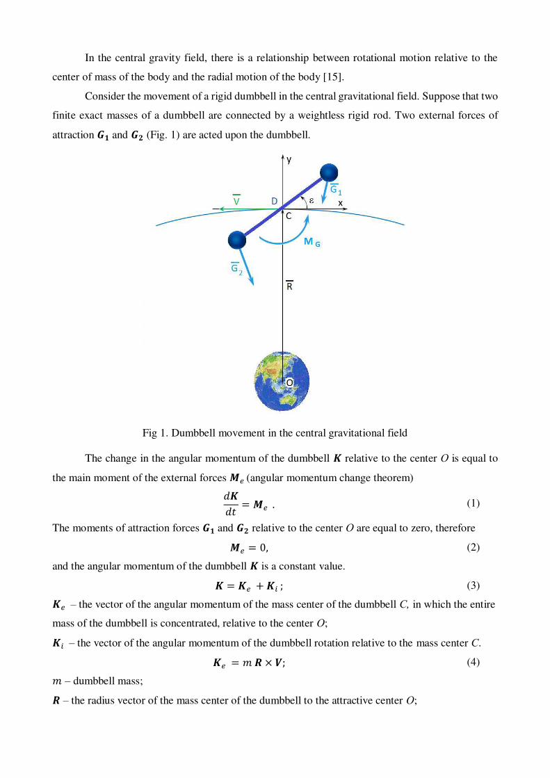
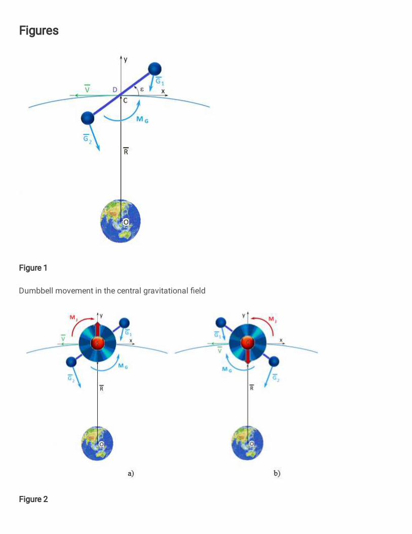
Consider the movement of a rigid dumbbell in the central gravitational field. Suppose that two
finite exact masses of a dumbbell are connected by a weightless rigid rod. Two external forces of
attraction 𝑮𝟏 and 𝑮𝟐 (Fig. 1) are acted upon the dumbbell.
Fig 1. Dumbbell movement in the central gravitational field
The change in the angular momentum of the dumbbell 𝑲 relative to the center О is equal to
the main moment of the external forces 𝑴𝑒 (angular momentum change theorem) 𝑑𝑲𝑑𝑡 = 𝑴𝑒 . (1)
The moments of attraction forces 𝑮𝟏 and 𝑮𝟐 relative to the center О are equal to zero, therefore 𝑴𝑒 = 0, (2)
and the angular momentum of the dumbbell 𝑲 is a constant value. 𝑲 = 𝑲𝑒 + 𝑲𝑖 ; (3) 𝑲𝑒 – the vector of the angular momentum of the mass center of the dumbbell С, in which the entire
mass of the dumbbell is concentrated, relative to the center О; 𝑲𝑖 – the vector of the angular momentum of the dumbbell rotation relative to the mass center С. 𝑲𝑒 = 𝑚 𝑹 × 𝑽; (4) 𝑚 – dumbbell mass; 𝑹 – the radius vector of the mass center of the dumbbell to the attractive center О;

𝑽 – the velocity vector of the mass center С of the dumbbell. 𝑲𝑖 = 𝐽𝐷 𝛀; (5) 𝐽𝐷 – the moment of inertia of the dumbbell in the plane of motion relative to the center С, the
central axial (binormal) moment of inertia; 𝛀 – absolute angular speed of the dumbbell rotation.
When the dumbbell deviates from the local vertical, relative to the center С, a moment of
forces 𝑮𝟏 and 𝑮𝟐 arises, tending to return the dumbbell to a position along the local vertical [11]: 𝑀𝐺 = 3μ0 𝐽𝐷𝑅3 Sin2ε; (6) ε – the angle between the axis Сх of the orbital coordinate system Схyz and the line connecting the
end elements of the dumbbell; μ0 = 3,986 ∙ 1014 м3/с2 – geocentric gravitational constant of the Earth.
The maximum value of 𝑀𝐺 at ε = π/4. To maintain a given position of the dumbbell at an
angle ε, a counterbalancing moment 𝑀𝐽 (𝑀𝐺 = 𝑀𝐽) is required, which can be created using a
flywheel. 𝑀𝐽 = 𝐽ω̇; (7) 𝐽 – flywheel moment of inertia; ω̇ – angular acceleration of the flywheel rotation.
As a result, spinning the flywheel to a certain angular velocity ω, the angular momentum 𝑲𝑖 changes, and, consequently, the angular momentum 𝑲𝑒 . The limitation on the maximum change in 𝑲𝑒 is due to the limiting angular velocity of the flywheel rotation.
Fig. 2 shows a diagram of the radial movement of the mass center of the dumbbell С. By
changing the direction of the flywheels rotation, the movement of the system can be carried out up
(Fig. 2 a) and down (Fig. 2 b). The travel range is limited by the maximum angular speed of the
flywheel rotation. Having a group of flywheels with different heights of orbits in one plane, it is
possible to implement a scheme for the movement of oncoming traffic flows without fuel
consumption. To spin the flywheels, it is enough electricity from power sources (for example, solar
panels). However, the technical implementation and efficiency of orbital maneuvers of this scheme
is inferior to maneuvers for the exchange of kinetic energy with the use of tether systems technologies
[16, 17].

a) b)
Fig. 2. Scheme of movement in the radial direction
The fact of the relationship between rotational motion around the mass center and radial
motion is observed in nature. Every year the Moon moves away from the Earth by 3.8 cm, while the
Earth slows down its angular velocity of rotation [18].
Thus, the relationship between the rotational motion of the body relative to the mass center
and the radial motion of the body is shown. It should be noted that there is no violation of the
conservation law of the mass center position. The center of the gravitational field О (the mass center
of a closed system, and more strictly - the mass center of the Earth-dumbbell system), as well as the
mass center of the Earth-Moon system, does not change its position. Only the position of the bodies
relative to the common mass center changes.
3. Quantum mechanics
It is known from quantum mechanics [19] that elementary particles have spin (intrinsic
angular momentum), which has a quantum nature and it is not associated with the movement of the
particle as a whole.
Let use elementary particles as flywheels (Fig. 3). 𝑚 𝑹 × ∆𝐕𝑲 = 𝑛 𝒔 ℎ2π ; (8) ∆𝑽𝑲 – the vector of change in the velocity of an object of mass m, in the case of a change in its angular
momentum 𝑲 due to the radiation of n elementary particles;
s – the spin vector of an elementary particle;
h – Planck's constant (ℎ = 6.626070040 ∙ 10−34 J ∙ s).

Fig. 3. Motion based on the use of the elementary particles spin
Assuming the change in the direction of the velocity ∆𝑽𝑲 𝑹, in scalar form 𝑚 𝑅 ∆𝑉𝐾 = 𝑛 𝑠 ℎ2π (9)
or 𝑚 ∆𝑉𝐾 = 𝑛 𝑠 ℎ2π𝑅 . (10)
Let us consider the last expression from the point of view of energy consumption during
movement based on the application of changes in angular momentum and momentum (jet
propulsion). To estimate energy costs based on the use of jet propulsion, let us consider a photon
engine that can develop the maximum thrust possible for a jet engine in terms of the expended mass
of the moved object. 𝑚 ∆𝑉𝐽 = 𝑛 ℎλ , (11) ∆𝑉𝐽 – the vector of change in the speed of an object of mass m in the case of jet propulsion due to the
emission of n photons with a wavelength . In this case, energy costs for movement:
∆𝐸𝐽 = 𝑛 ℎ 𝑐λ , (12)
where с – the speed of light.
The momentum of the same n photons, using their spin for the movement of an object, is determined
by expression (10), and the energy costs for moving an object of mass m: ∆𝐸𝐾 = 𝑛 𝑠 ℎ 𝑐2π𝑅 . (13)
From expressions (12) and (13) it follows that for λ > 2π𝑅/𝑠 , to change the velocity of an object in
a central field at a distance R from the center of attraction, it is energetically more advantageous to
use the angular momentum of an elementary particle in comparison with its momentum (jet motion).
In this case, the emission of low-energy particles should be carried out in the direction perpendicular
to the plane of motion (Fig. 3). The results obtained theoretically prove the possibility and energy
feasibility of implementing the idea of creating a thrust based on a change in the kinetic moment for
the development of transport facilities based on new physical principles.
Let's evaluate the practical possibility of implementing the idea. In recent decades, several
promising approaches to solving the problem of quantizing gravity have been developed: string
theory, loop quantum gravity, and others. The proposed theories are confirmed by the observed
phenomena in astrophysics and thought experiments. As a consequence of the principle of particle-
wave dualism for the description of the gravitational field, the hypothesis of the existence of gravitons
is actively considered.
4. Application of gravitons
The Compton graviton wavelength λ𝑔 > 1 ∙ 1016 m [20], which is much larger than the
Earth's radius (6,371,000 m) and the distance from the Earth to the Sun (149,600,000,000 m). Thus,
if gravitons are used for motion, then using their spin (angular momentum) is a billion times more
profitable than using them in jet motion near the Earth's surface. The spin vector s (direction of
emission) is directed perpendicular to the plane of motion of the object.
Let's estimate the acceleration that the object receives: 𝑎 = ∆𝑉∆𝑡 = 𝑠 ℎ2π𝑅𝑚∆𝑡 . (14)
The possibility of controlling quantum processes with an accuracy of up to three attoseconds has been
proven (∆𝑡 = 3 ∙ 10−18 s) [21]. Spin graviton 𝑠 = 2. Neutron (proton) mass 1.675⋅10-27 kg (𝑚 =1.675 ∙ 10−27 kg). 𝑅 = 6.371 ∙ 106 m. Then acceleration will act on each neutron (proton) 𝑎 =6,600 m/s2.
It is necessary that all atoms of the object simultaneously emit low-energy particles for
macroobjects to move with such accelerations without internal deformation. Thus, we get movement
without overload. For the practical implementation of the idea, it is necessary to obtain directed flows
of low-energy particles.
5. About the law of momentum conservation

An example with gravitons and a diagram of the movement of an object in the radial direction
(Fig. 2) give grounds for putting forward the hypothesis about the presence of emission/absorption of
elementary particles with spin.
A material body emits/absorbs elementary particles with spin in a plane perpendicular to the
vector of its velocity of motion:
- when the body moves without acceleration, the emission is equal to the absorption;
- with slow motion of the body, the emission exceeds the absorption;
- with accelerated motion of the body, the absorption exceeds the emission.
To estimate the momentum of emitted/absorbed elementary particles, we write equation (10)
in the following form: 𝑚 ∆𝑉 = 𝑛 𝑠 ℎ2π 𝜌 , (15) 𝜌 – the average radius of space curvature in the vicinity of material quantum particles of the body,
due to the forces of gravitational attraction of the universe. The use of this scalar parameter in (15) is
due to the relationship between the rotational motion of the body relative to the mass center and the
radial motion of the body. The specific value of the introduced parameter for the subsequent
assessment of the momentum of the emitted/absorbed elementary particles is of no fundamental
importance.
An impulse 𝐼𝑒 of radiation emission/absorption 𝐼𝑒 = 𝑛 𝑠 ℎ2π 𝜌 (16)
appears as a result of a change in the speed of a body and can be transmitted to other bodies. As a
consequence, the law of conservation of momentum takes on a broader interpretation: the momentum
of the system and the emission/absorption momentum of elementary particles for a closed system is
a constant value, regardless of the type of interaction of the bodies of the system (elastic or inelastic
impact).
As a confirmation of the hypothesis put forward, let us consider a number of examples from
different areas of physics and the results of experiments with the motion of bodies in the vacuum.
6. Examples of physic phenomena
Well-known experiment: electron diffraction by a slit (Fig. 4). The appearance of the
perpendicular component of the electron momentum after passing through the slit confirms the
hypothesis of the presence of emission/absorption of low-energy particles, and the quantum
uncertainty of elementary particles may be due to this emission.

Fig. 4. Diffraction of electrons by the slit
Fig. 5 shows frames from a slow-motion video of a drop falling [22]. As a result of the central
inelastic impact, the liquid spreads out in the plane perpendicular to the motion of the drop.
Fig. 5. Central inelastic impact of a liquid drop
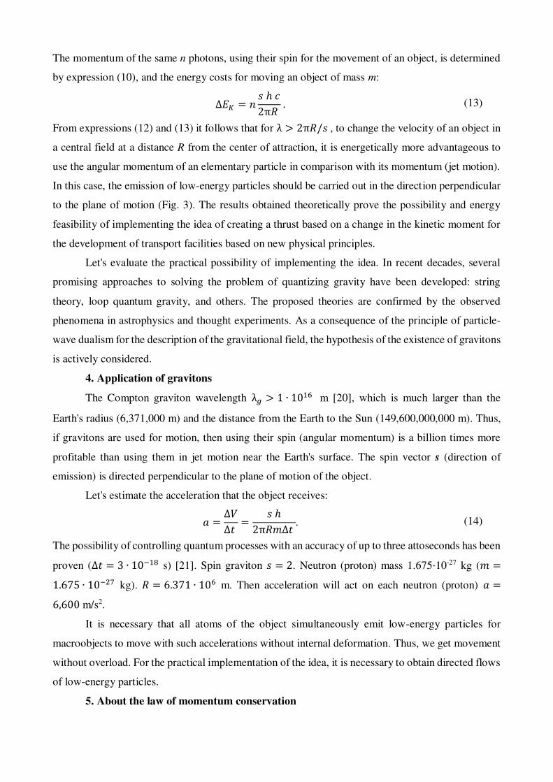
In the frames of slow-motion shooting [23] of a pistol shot (Fig. 6), the movement of powder
gases in the plane perpendicular to the movement of the bullet is observed.
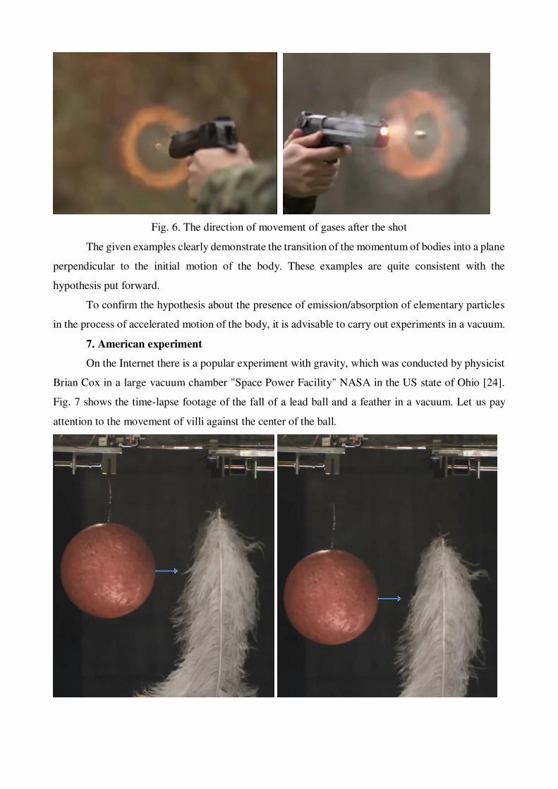
Fig. 6. The direction of movement of gases after the shot
The given examples clearly demonstrate the transition of the momentum of bodies into a plane
perpendicular to the initial motion of the body. These examples are quite consistent with the
hypothesis put forward.
To confirm the hypothesis about the presence of emission/absorption of elementary particles
in the process of accelerated motion of the body, it is advisable to carry out experiments in a vacuum.
7. American experiment
On the Internet there is a popular experiment with gravity, which was conducted by physicist
Brian Cox in a large vacuum chamber "Space Power Facility" NASA in the US state of Ohio [24].
Fig. 7 shows the time-lapse footage of the fall of a lead ball and a feather in a vacuum. Let us pay
attention to the movement of villi against the center of the ball.
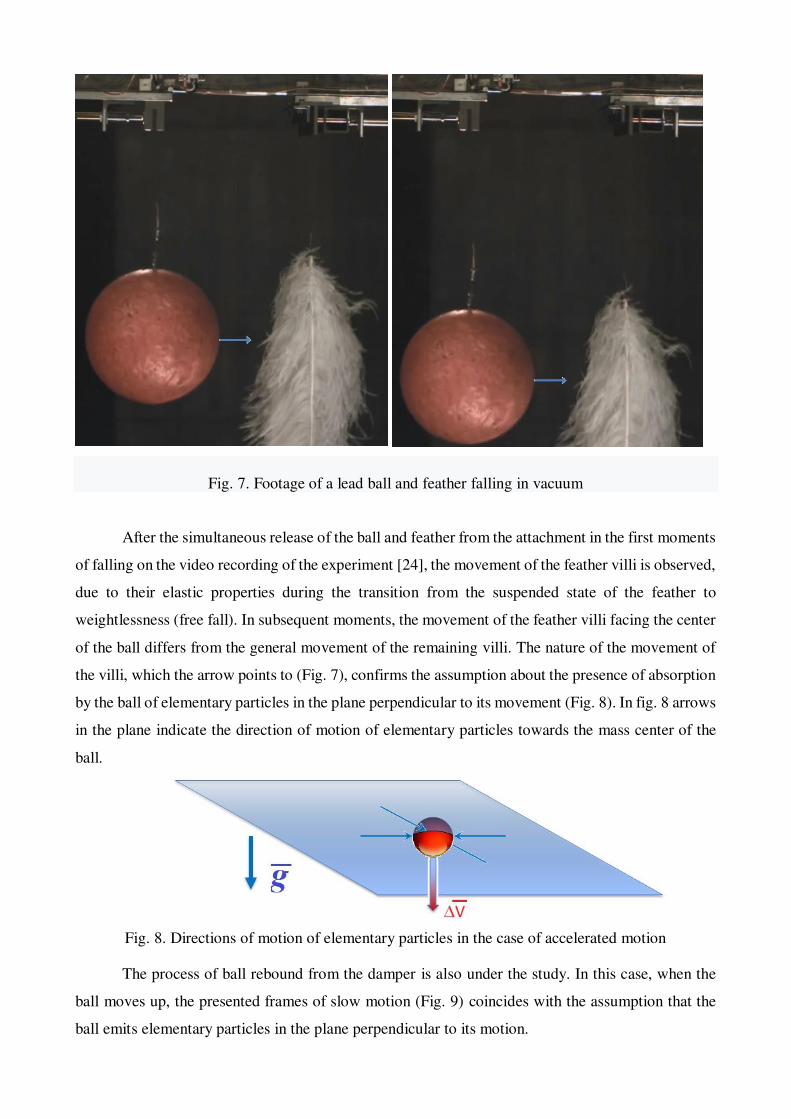
Fig. 7. Footage of a lead ball and feather falling in vacuum
After the simultaneous release of the ball and feather from the attachment in the first moments
of falling on the video recording of the experiment [24], the movement of the feather villi is observed,
due to their elastic properties during the transition from the suspended state of the feather to
weightlessness (free fall). In subsequent moments, the movement of the feather villi facing the center
of the ball differs from the general movement of the remaining villi. The nature of the movement of
the villi, which the arrow points to (Fig. 7), confirms the assumption about the presence of absorption
by the ball of elementary particles in the plane perpendicular to its movement (Fig. 8). In fig. 8 arrows
in the plane indicate the direction of motion of elementary particles towards the mass center of the
ball.
Fig. 8. Directions of motion of elementary particles in the case of accelerated motion
The process of ball rebound from the damper is also under the study. In this case, when the
ball moves up, the presented frames of slow motion (Fig. 9) coincides with the assumption that the
ball emits elementary particles in the plane perpendicular to its motion.

Fig. 9. Frames of the rebound of the ball and feathers in vacuum
The directions of motion of elementary particles from the mass center of the sphere are
indicated by arrows in the plane in Fig. 10.
Fig. 10. Directions of movement of elementary particles in the case of slow motion

In the above experiment, feathers play the role of a detector that records the flow of passing
elementary particles. The number of these 𝑛𝑑 particles can be estimated based on the equation (4): 𝑛𝑑 = 𝑚 ∆𝑉 2𝜋 𝜌 𝑠 ℎ ∙ 𝑑 𝑉 ∆𝑡2𝜋 𝑙 𝑉 ∆𝑡 = 𝑚 ∆𝑉 𝜌 𝑑𝑠 ℎ 𝑙 ; (17) 𝑉 – the speed of the body (ball) relative to the detector (Fig. 11); ∆𝑡 – the time interval during which the speed of the body (ball) changes by Δ𝑉 with respect to the detector; 𝑑 – width of the detector (villi) in the plane of emission/absorption by the body (ball) of elementary
particles (Fig. 11); 𝑙 – the distance from the detector (villi) to the mass center of the ball (Fig. 11).
Thus, the area 𝐴 = 𝑑 ∙ 𝑉 ∙ ∆𝑡 crosses 𝑛𝑑 elementary particles in time ∆𝑡.
Fig. 11. Scheme for calculating the particle flux through detector A
n the case of a free fall of a body (ball) with acceleration 𝑔, the dependence of the change in
velocity ∆𝑉 on the change in the height of the ball ∆𝐻 is determined as follows: ∆𝐻 = 𝑉0 ∙ ∆𝑡 + 𝑔 ∙ ∆𝑡22 , ∆𝑉 = 𝑔 ∙ ∆𝑡 , (18)
where 𝑉0 – the initial speed of the body – (ball); ∆𝐻 = 𝑉0 ∙ ∆𝑉𝑔 + ∆𝑉22 ∙ 𝑔 ; (19)
∆𝑉 = √𝑉02 + 2𝑔 ∆𝐻 − 𝑉0 . (20)
Then, taking into account (17) and (20), the number of particles 𝑛𝑑 passing through the
detector with height ∆𝐻 is 𝑛𝑑 = 𝑚 𝜌 𝑑𝑠 ℎ 𝑙 (√𝑉02 + 2𝑔 ∆𝐻 − 𝑉0). (21)
The function 𝑛𝑑(𝑉0), defined by expression (21), for positive values of ∆𝐻 has a negative
derivative: 𝑛𝑑′ (𝑉0) < 0,, therefore, the function𝑛𝑑(𝑉0) is decreasing, and its maximum value is
attained at 𝑉0 = 0: 𝑛𝑑 𝑚𝑎𝑥 = 𝑚 𝜌 𝑑𝑠 ℎ 𝑙 √2𝑔 ∆𝐻. (22)

Let us estimate the Compton wavelength of an elementary particle based on the principle of
equivalence of mass and energy.
When the speed of a body changes, its relativistic mass changes:
∆𝑚 = 𝑚𝑟𝑒𝑙 − 𝑚 = 𝑚 (1 √1 − ∆𝑉2𝑐2⁄ − 1) = 𝑚 ∆𝑉22 𝑐2 , (23)
Based on the energy conservation law, the radiation energy of elementary particles 𝐸 with the
Compton wavelength 𝜆 𝐸 = 𝑛 ℎ𝜈 = 𝑛 ℎ 𝑐𝜆 (24)
cannot exceed the change in the energy of the body due to the relativistic effect: 𝑛 ℎ 𝑐𝜆 ≤ ∆𝑚𝑐2 . (25)
Taking into account equations (15) and (23), we obtain 𝑐𝜆 ≤ 𝑠 ∆𝑉 4 𝜋 𝜌 . (26)
The maximum value ∆𝑉 = 𝑐 and inequality (26) takes the form 𝜆 ≥ 4 𝜋 𝜌𝑠 . (27)
Constraint (27) can only be satisfied by very low-energy particles. For example, the Compton
wavelength of a hypothetical particle graviton λ𝑔 > 1 ∙ 1016 m [20].
8. The Russian experiment
Low-energy particles, satisfying condition (27), have energy far beyond the measurement
error of the Large Hadron Collider. However, according to the given hypothesis, there is emission
from a stream of low-energy particles with spin. The difference in the number of particles 𝑛𝑑 between
the number of emitted and absorbed body particles is determined by expressions (17), (21) or (22).
In these expressions, there is a change in the body's velocity ∆𝑉 with respect to the detector or a
change in height ∆𝐻 and an acceleration 𝑔, i.e. a relative accelerated motion is required between the
detector and the body to register the emission.
To detect the flow of these particles, the authors carried out an experiment on the basis of the
"Scientific Testing Center of the Rocket and Space Industry" (STC RSI) of the State Corporation
"Roscosmos" in the vacuum chamber with a volume of 4 m3 (diameter 1.6 m, length 2 m). In the
upper part of the vacuum chamber, a mechanical, electrically driven device for the simultaneous
release of a cast-iron ball weighing 7.26 kg with a diameter of 11 cm, a bundle of ostrich feathers and
a GoPro 8 HERO Black video camera providing slow-motion shooting with a frequency of 240
frames per second in HD. A garland of ostrich and decorative feathers on a cotton thread (emission

detector) was placed on an independent suspension in the form of a steel wire (removes a static
charge) next to the ball's fall path. The vacuum chamber also contained a stationary video camera, a
tripod with vertically positioned halogen car lamps, rubber mats to dampen the impact of the ball,
and green polyurethane mats to ensure the quality of shooting (Fig. 12)
Fig. 12. Equipment for the experiment in the vacuum chamber of the STC RSI
A video recording of the ball falling from a height of 1.1 m made by stationary and mobile
GoPro video cameras in vacuum conditions. The ball was dropped four times.
During the first attempt, a small decorative feather with a steel ring was dropped for
attachment to the release device. The feather served as an indicator of the purity of the vacuum – the
feather fell in front of the ring. The pressure in the chamber was 0.08 mm Hg. The drop device worked
normally, but the mobile video camera failed. The backlight consisted of two car lamps, which
influenced the low brightness of the shooting. Additionally, panoramic shooting was carried out on
the iPhone 8 from the outside through the porthole of the vacuum chamber. Using a stationary GoPro
camera, it was possible to record the attraction of the feather by the ball at the final stage of the fall
at the bottom of the garland (Fig. 13). When the ball moves, a change in the angle of the feather of a
stationary garland opposite the center of the ball is recorded. This fact is consistent with the diagram
in Fig. 11. The purity of the experiment is questioned by the touch of a falling feather in the middle
of the garland. However, in the opinion of the authors (after careful study of the video recording),
this did not affect in detail the revealed fact. It was not possible to study in detail the feathers of a
falling feather by a stationary GoPro camera. The camera crash was caused by a software crash while
working in WiFi mode with an iPhone 8 (after turning on the camcorder, the connection was lost). A

manual reboot of the chamber was required, which could only be realized after depressurization and
opening of the chamber.
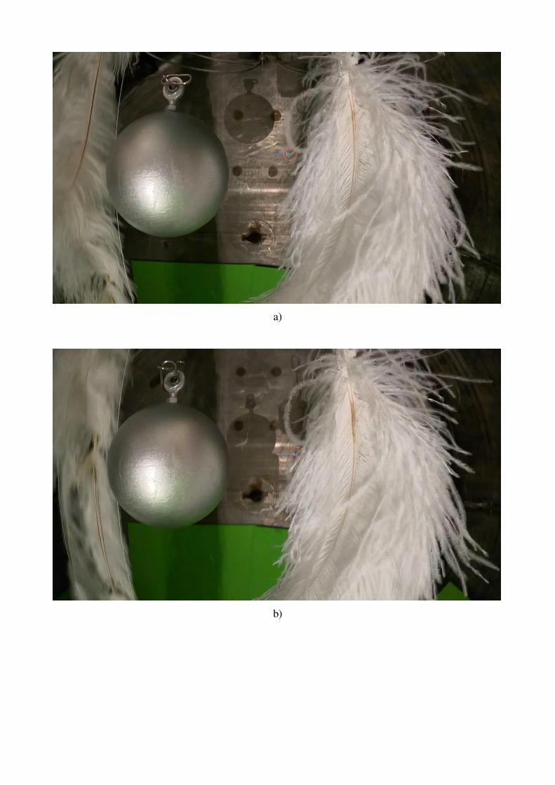
a)
b)
Fig. 11. Fragments of video recording frames. Changing the angle of the fluff relative to the
vertical: a) before the flight of the ball, b) during the flight of the ball
During the second attempt, the drop device and video cameras worked normally. The
backlight consisted of four automotive lamps arranged vertically along a stand. The pressure in the
chamber was 0.08 mm Hg. A bunch of ostrich feathers were dropped. At the moment of transition
from a suspended state to a state of weightlessness (falling), the fluffs move relative to the ball (there
is ∆𝑉). The advantage of this type of motion is that there is no gravity load on the fluff and that the
maximum flow of low-energy particles is ensured (21). A clear anomaly in the movement of feathers
against the center of the ball is observed in the American experiment described above (Fig. 8). In the
presence of attraction from the side of the ball, the oscillation period of the fluffs close to the
horizontal plane of the section passing through the mass center of the ball should decrease. The
presented frames from the GoPro mobile camera show the oscillation of a fluff close to the above
plane (Fig. 14). The frequency of its oscillations is higher than that of the others: the fluff manages
to make two complete oscillations, while the rest is no more than 1.5. In the first frame (Fig. 14 a),
the fluff is deflected by the maximum amplitude from the vertical. In the second frame (Fig. 14 b),
the fluff is pressed back to the feather.
a)
b)

c)
d)
Fig. 14. Video footage of a fall of the ostrich feathers bunch from a falling video camera
In the third frame (Fig. 14c), the fluff again deflects to its maximum amplitude (somewhat
less than in the first frame - damped oscillations) towards the ball. In the fourth frame (Fig. 14d), the
fluff again tends to the vertical. In the same frame, a new fluff appears for the first time, clearly
opposite the center of mass of the ball, slightly lower than the previously considered fluff. Its
appearance may be due to the presence of radiation of low-energy particles in the direction of the
ball, in particular, this radiation could serve as a trigger when removing it from the engaged position.

а) б)
Fig. 15. Frames and fragments of video recordings of the change in the position of the fluff relative
to the vertical: a) before the flight of the ball, b) after the flight of the ball
Video footage of the ball falling and the deflection of the garland fluffs from a stationary
(suspended on an independent thread) GoPro video camera was obtained (Fig. 15 - 17).

When comparing fragments of frames (Fig. 15) before and after the flight of the ball next to
the fluff (indicated by the arrow), its deviation towards the ball is observed. Similar deflections of
fluffs are observed at other moments of the ball's falling (Fig. 16 and Fig. 17).
a) b)
Fig. 16. Frames and fragments of video recordings of the change in the position of the fluff relative
to the vertical: a) before the flight of the ball, b) after the flight of the ball

a) b)
Fig. 17. Frames and fragments of video recordings of changes in the position of fluffs:
a) before the flight of the ball, b) after the flight of the ball
On the third attempt, the chamber pressure was 0.07 mm Hg. Both cameras were stationary
(they were hung on threads). Two vertical plumb lines, a garland of decorative feathers (left) and a
garland of ostrich feathers (right) were located along the flight path of the ball on different sides (Fig.
18). When falling, the ball touched the decorative feathers of the left garland; therefore, the analysis
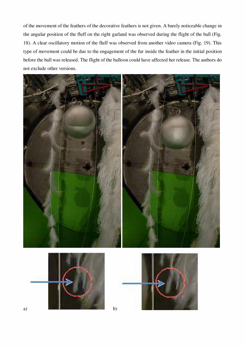
of the movement of the feathers of the decorative feathers is not given. A barely noticeable change in
the angular position of the fluff on the right garland was observed during the flight of the ball (Fig.
18). A clear oscillatory motion of the fluff was observed from another video camera (Fig. 19). This
type of movement could be due to the engagement of the fur inside the feather in the initial position
before the ball was released. The flight of the balloon could have affected her release. The authors do
not exclude other versions.
a) b)

Fig. 18. Frames and fragments of changing the fluff position relative to the vertical: a) before the
flight of the ball, b) after the flight of the ball
Fig. 19. Frames of changes in the position of the fluff relative to the vertical
On the fourth attempt, the chamber pressure was 0.16 mm Hg. Two vertical plumb lines, a
garland of large ostrich feathers and two garlands (one of decorative, the other of ostrich) feathers
were located along the flight path of the ball on opposite sides. Each garland was weighted with a

weight (20 mm iron nut) at the lowest point. Subtle deviations of the fluffs of the garlands were
observed opposite the center of the falling ball.
The ball bounced about 30 cm after a strong impact on the damper at the bottom of the vacuum
chamber. This circumstance influenced the conditions of the experiment and did not allow testing the
hypothesis in terms of body emission.
The authors plan to conduct an experiment in a vacuum chamber 8 m high on the basis of STC
RSI using higher-speed video cameras. From equations (21) and (22) it follows that the maximum
effect from the emission of low-energy particles should be observed at 𝑉0 = 0 and large accelerations.
Therefore, special attention will be paid to the beginning of the fall (𝑉0 = 0), the moment of the
rebound when hitting the damper (large acceleration) and the moment the ball hovers in the upper
part of the trajectory after the rebound (change in the direction of emission of low-energy particles).
It is planned to illuminate detectors (fluffs) with lasers, install ring-shaped garlands along the path of
falling bodies of various shapes, develop and use a device for ejecting bodies vertically upward to a
height of more than 1 m.
The numerous examples of the movement of fluffs in a vacuum given in this section, obtained
as a result of each of the four drops of the ball in the framework of the experiment on the basis of the
STC RSI, are consistent with the given hypothesis. The authors invite interested researchers to
conduct a similar experiment.
9. Massless engine technology
According to the proposed hypothesis, a device creating thrust without mass consumption
should provide high-frequency oscillations of the working fluid and receive a useful flow of low-
energy elementary particles with spin. The most famous attempts to implement such devices are EM-
Drive Thruster [25, 26] and Mach effect thruster [27].
It is necessary to carry out additional experiments in order to study the generation of directed
flows of low-energy elementary particles and the possibility of their reception to create more efficient
devices. Different directions and intensities of low-energy particle fluxes are expected for working
bodies of different shapes. Receiving useful low-energy fluxes, forming thrust, is achieved by moving
the receiver in the direction of emission of particles at the time of their generation and subsequent
removal of the receiver when changing the direction of emission.
10. About the theory of quantum gravity
Among the majority of modern theories of gravity, the theory of gravity with torsion is
recognized as an extension of the general theory of relativity [28]. Currently, there are active attempts
to construct a quantum theory of gravity, the main directions are considered to be string theory [29]
and loop quantum gravity [30]. The main problem in confirming the proposed theories is the difficulty
in conducting experiments to search for low-energy particles [31].

The demand for consistency between a quantum description of matter and a geometric
description of spacetime a theory is required in which gravity and the associated geometry of
spacetime are described in the language of quantum physics [28]. Despite major efforts, no complete
and consistent theory of quantum gravity is currently known, even though a number of promising
candidates exist.
Well-known experiments with gravity were carried out in two directions: 1) measurement of
the force of gravitational attraction between material bodies; 2) measurements of gravitational waves
(changes in the gravitational field, space-time); and are not associated with the registration of low-
energy particle fluxes interacting with material bodies. A similar interaction is observed in
astrophysics (the phenomenon of "dark matter"). In case of proper experimental confirmation, the
given hypothesis about the emission / absorption of low-energy particles by bodies will make it
possible to establish a connection between gravity and the physics of the microworld, classical and
quantum mechanics.
The given hypothesis is consistent with the basic laws of physics: the law of conservation of
momentum, the law of conservation of angular momentum, the law of conservation of energy, and
the law of conservation of the position of the mass center.
As regards the latter, it should be noted that it does not hold in relativistic mechanics. Let's
look at a simple example. Two bodies of different masses, forming a closed system, move in a straight
line towards each other, for example, by gravity. The speed of an object with a smaller mass increases
more than that of another object, i.e. its relativistic mass increases faster (28). This means that the
mass center of the system shifted towards the object with a smaller mass. In the case of the given
hypothesis, the mass center of the system does not change due to the inclusion of emission.
11. Conclusion
1) The possibility and energy feasibility of implementing the idea of creating a thrust based on a
change in the kinetic moment for the development of transport objects based on the new physic
principles has been theoretically proved.
2) The practical implementation of the idea requires additional fundamental research and
experimental confirmation of the fluxes of low-energy elementary particles with spin.
3) The proposed hypothesis, the given examples and experiments give grounds for the formation of
new physic concepts of the speed, mass and inertia of bodies.
4) The results obtained can be used in experiments to search for low-energy elementary particles.
5) Devices creating thrust without mass consumption should provide high-frequency oscillations of
the working fluid and receive a useful flow of low-energy elementary particles with spin.
Acknowledgments

This paper has been supported by the RUDN University Strategic Academic Leadership
Program.
References
[1] K.E. Tsiolkovsky, Exploration of the world spaces by reactive devices: (reprinting works of 1903
and 1911 with some changes and additions), Kaluga: 1st Guest. GSNH, 1926.
[2] Wikipedia, Non-rocket spacelaunch. https://en.wikipedia.org/wiki/Non-rocket_spacelaunch,
2020 (accessed 12 December 2020).
[3] Wikipedia, Orbital Skyhook. https://en.wikipedia.org/wiki/Skyhook_(structure), 2020 (accessed
12 December 2020).
[4] Wikipedia, Solar sail. https://en.wikipedia.org/wiki/Solar_sail, 2020 (accessed 12 December
2020).
[5] Wikipedia, Ion thruster. https://en.wikipedia.org/wiki/Ion_thruster, 2020 (accessed 12 December
2020).
[6] Wikipedia, Laser propulsion. https://en.wikipedia.org/wiki/Laser_propulsion, 2020 (accessed 12
December 2020).
[7] R. Shawyer, second generation EmDrive propulsion applied to SSTO launcher and interstellar
probe, Acta Astronaut. 116 (2015) 166–174. https://doi.org/10.1016/j. actaastro.2015.07.002.
[8] H. Fearn, N. van Rossum, K. Wanser, J.F. Woodward, Theory of a Mach effect thruster II, J. Mod.
Phys. 06 (2015) 1868–1880. https://doi.org/10.4236/jmp. 2015.613192.
[9] Wikipedia, Warp drive. https://en.wikipedia.org/wiki/Warp_drive, 2020 (accessed 12 December
2020).
[10] Commission for Combating Pseudoscience RAS. http://klnran.ru/en/category/commission/,
2020 (accessed 12 December 2020).
[11] V.V. Beletsky, E.M. Levin, Dynamics of Space Tether Systems, Univelt, San Diego, CA, 1993.
[12] V.V. Beletsky, Essays on the Motion of Celestial Bodies, Birkhäuser, Basel, 2001.
[13] H. Troger, A.P. Alpatov, V.V. Beletsky, V.I. Dranovskii, V.S. Khoroshilov, A.V. Pirozhenko,
A.E. Zakrzhevskii, Dynamics of Tethered Space Systems, CRC Press, New-York, 2010.
[14] J.V. Breakwell, J.W. Gearhart, Pumping a Tethered Configuration to Boost its Orbit Around an
Oblate Planet, Journal of the Astronautical Sciences, 35 (1987) 19-39.
[15] D.B. Spencer, Yu.N. Razoumny, S.A. Kupreev. Principle of motion based on the kinetic
moment, Advances in the Astronautical Sciences, 174 (2021) 301-307.
[16] J.D. Isaacs, A.C. Vine, H. Bradner, G.E. Bachus, Satellite elongation into a true "sky-hook",
Science, 151 (1966) 682-683. https://doi.org/10.1126/science.151.3711.682.
[17] J. Pearson, The orbital tower: A spacecraft launcher using the Earth's rotational energy, Acta
Astronautica, 2 (1975) 785-799. https://doi.org/10.1016/0094-5765(75)90021-1.

[18] C.D. Murray, S.F. Dermott, Solar System Dynamics. Cambridge University Press, UK, 1999.
[19] L.D. Landau, E.M. Lifshitz, Quantum Mechanics: Non-Relativistic Theory. Pergamon Press,
UK, 1977.
[20] B.P. Abbott, 2018. Erratum: GW170104: Observation of a 50-solar-mass binary black hole
coalescence at redshift 0.2. Physical Review Letters. 121, e129901.
https://doi.org/10.1103/PhysRevLett.121.129901.
[21] L. Giannessi, E. Allaria, K.C. Prince, C. Callegari, G. Sansone, K. Ueda, T. Morishita, C.N. Liu,
A.N. Grum-Grzhimailo, E.V. Gryzlova, N. Douguet, K. Bartschat, 2018. Coherent control schemes
for the photoionization of neon and helium in the Extreme Ultraviolet spectral region. Scientific
Reports. 8, e7774. https://doi.org/10.1038/s41598-018-25833-7.
[22] Youtube, Slow motion video of a drop of liquid.
https://www.youtube.com/watch?v=rlMQob_P9C0, 2020 (accessed 12 December 2020).
[23] Youtube, Slow motion video of a pistol shot.
https://www.youtube.com/watch?v=hnHXk2bpArA, 2020 (accessed 12 December 2020).
[24] BBC, Brian Cox visits the world’s biggest vacuum. https://www.discovermagazine.com/the-
sciences/watch-a-feather-and-bowling-ball-fall-at-the-same-speed, 2020 (accessed 12 December
2020).
[25] R. Shawyer, 2019. EmDrive thrust/load characteristics. Theory, experimental results and a moon
mission. Proceedings of the International Astronautical Congress, 2019-October, eIAC-
19_C4_10_14_x48783.
[26] M. Kößling, M. Monette, M. Weikert, M. Tajmar, The SpaceDrive project - Thrust balance
development and new measurements of the Mach-Effect and EMDrive Thrusters, Acta Astronautica,
161 (2019) 139-152. https://doi.org/ 10.1016/j.actaastro.2019.05.020.
[27] H. Fearn, N. van Rossum, K. Wanser, J.F. Woodward, Theory of a Mach effect thruster II, J.
Mod. Phys. 06 (2015) 1868–1880, https://doi.org/10.4236/jmp. 2015.613192.
[28] Wikipedia, General relativity. https://en.wikipedia.org/wiki/General_relativity, 2020 (accessed
12 December 2020).
[29] Wikipedia, String theory. https://en.wikipedia.org/wiki/String_theory, 2020 (accessed 12
December 2020).
[30] Wikipedia, Loop quantum gravity. https://en.wikipedia.org/wiki/Loop_quantum_gravity, 2020
(accessed 12 December 2020).
[31] S.P. Kumar, M.B. Plenio, 2020. On quantum gravity tests with composite particles. Nature
Communications. 11, e3900. https://doi.org/10.1038/s41467-020-17518-5.
Figures
Figure 1
Dumbbell movement in the central gravitational �eld
Figure 2

Scheme of movement in the radial direction
Figure 3
Motion based on the use of the elementary particles spin
Figure 4
Diffraction of electrons by the slit

Figure 5
Central inelastic impact of a liquid drop
Figure 6
The direction of movement of gases after the shot

Figure 7
Footage of a lead ball and feather falling in vacuum
Figure 8
Directions of motion of elementary particles in the case of accelerated motion

Figure 9
Frames of the rebound of the ball and feathers in vacuum
Figure 10
Directions of movement of elementary particles in the case of slow motion
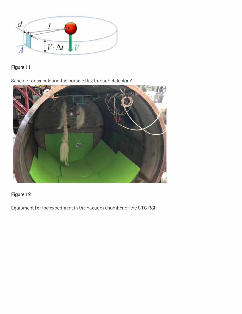
Figure 11
Scheme for calculating the particle �ux through detector A
Figure 12
Equipment for the experiment in the vacuum chamber of the STC RSI
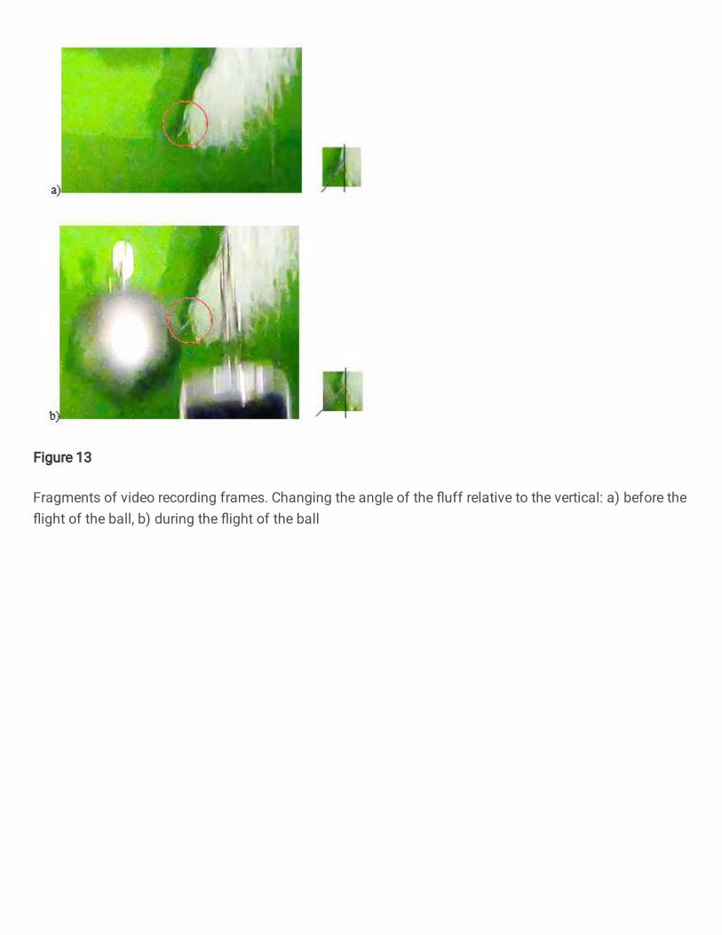
Figure 13
Fragments of video recording frames. Changing the angle of the �uff relative to the vertical: a) before the�ight of the ball, b) during the �ight of the ball

Figure 14
Video footage of a fall of the ostrich feathers bunch from a falling video camera

Figure 15
Frames and fragments of video recordings of the change in the position of the �uff relative to the vertical:a) before the �ight of the ball, b) after the �ight of the ball

Figure 16
Frames and fragments of video recordings of the change in the position of the �uff relative to the vertical:a) before the �ight of the ball, b) after the �ight of the ball

Figure 17
Frames and fragments of video recordings of changes in the position of �uffs: a) before the �ight of theball, b) after the �ight of the ball

Figure 18
Frames and fragments of changing the �uff position relative to the vertical: a) before the �ight of the ball,b) after the �ight of the ball

Figure 19
Frames of changes in the position of the �uff relative to the vertical