Embed Size (px)
Citation preview
THE COMPANY
EASI-JOIST TECHNICAL GUIDE2
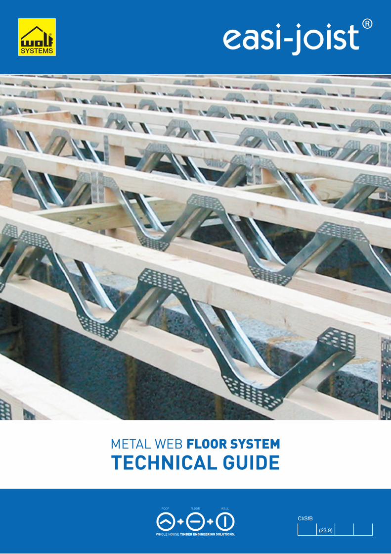
IntroductionWolf Systems provide products andservices to the timber engineeringindustry. We manufacture and supplynailplates, metal webs and software forthe design and manufacture of rooftrusses, metal web joists and timberframe wall panels. Additionally, we alsoprovide a comprehensive range ofmachinery for the manufacture of thesecomponents.
Company HistoryWolf Systembau was started by JohannWolf in 1966 in Scharnstein, Austria.The original activities of the companywere construction within the agriculturalindustry. This consisted of concretesilos and buildings constructed oftimber, steel and concrete, Thecompany then expanded into otherareas of the construction industry suchas industrial, commercial and domesticbuildings, manufacturing machinery forsawmills, timber frame wall panels androof trusses, as well as harvestingtimber from their own forests.
Having over 40 years experience intimber engineering, the Groupoperates from a state of the art officecomplex in Scharnstein, and employs3000 staff in 14 European countries.Wolf Systembau is still privatelyowned by Johann Wolf and his familyand all of the Group’s operations areconstruction related.
In the United Kingdom and Ireland,Wolf Systems has a network of over50 experienced trussed raftermanufacturers, supported by ourcomprehensive design and software,and specialist engineering office.
United KingdomWolf Systems was formed in 1988 asan integral part of Wolf Systembau’sexpansion into the world roof trusssystems market. Having successfullyestablished itself amongst itscompetitors, Wolf Systems now has anetwork of over 50 experienced trussedrafter manufacturers throughout theUnited Kingdom and Ireland.
Following the introduction of ourmarket leading roof truss designsoftware, we turned our expertise andknowledge of timber engineering toproducts and services for Floors andWalls. Expanding on the simple yet
comprehensive interface found in theRoof software, easi-joist® has fastbecome adopted by many of ourexisting customers, and significantlymanufacturers using competitorsystems. Together with products forRoofs and Floors, our Wall panelsoftware provides the completesolution for Whole House TimberEngineering design and manufacturing.
In addition to our products, ourCustomer Services and Design Team’sprovide expert technical support andbackup for software implementation,training and design.
UK Coventry Works
CONTENTS
EASI-JOIST TECHNICAL GUIDE 3
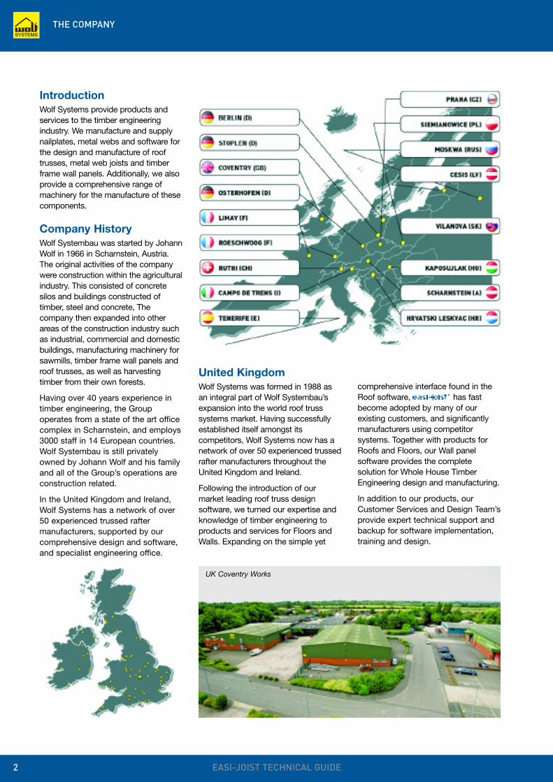
The easi-joist® floor system
offers clear benefits over sawn
timber and other engineered
floor joist systems. Not only
does it out-perform sawn
timber in span and
dimensional stability, the
added benefits of a greater
bearing area and open web
system makes it easier to
install for the carpenter,
plumber and electrician,
increasing valuable time and
reducing cost.
Contents
The Company 2
Industry Associations, Standards and Compliance 4
The easi-joist® System 5-7
Accommodation of Services 8
Floor Cassettes 9
Approvals 10-13
Properties and Performance 14-15
Strongbacks and Restraint Straps 16
Ground Floor Joists 17
Floor Design Factors 18-19
Floor Detailing Key 20-21
General Floor Detailing 22-23
Floor detailing in Masonry Construction 24
Floor Detailing in Timber Frame Construction 25-27
Metalwork 28
Roof Detailing 29
Notes on Installation 30
Health and Safety 31-32
Index 33
Glossary of Terms 34
Design and Services 35
ISO 9000 is theinternationallyrecognised standardfor an organisation'sinternal Quality
Management. The term 'quality' refersto all those features of a product orservice which are required by thecustomer.
An organisation's 'Quality Management'refers to an organisation's actions toensure that its products or servicessatisfy its customers' qualityrequirements and complies with anyregulations applicable to thoseproducts or services.
Wolf Systems supplies all its productsand services to ISO 9001 ensuring thehighest standards are provided by ourcompany.
The Irish TimberFrame Manufacturers'Association (ITFMA) isthe Trade Association
for the timber frame manufacturingindustry in Ireland. It is an independentlyconstituted company limited byguarantee with no share capital. All fullmembers are represented on the Boardof Directors. Voting on issues is notbased on turnover. The association isthe recognised representative body forTimber Frame Manufacturers on theIsland of Ireland and membership issynonymous with professionalism andquality. In addition, the ITFMA providemarketing, training and education of thetimber frame concept.
The Irish AgrémentBoard is designatedby Government toissue EuropeanTechnical Approvals.
Irish Agrément Board Certificatesestablish proof that the certifiedproducts are ‘proper materials’ suitablefor their intended use under Irish siteconditions, and in accordance with theBuilding Regulations 1997 to 2006.
The Irish Agrément Board operates inassociation with the NationalStandards Authority of Ireland (NSAI)as the National Member of UEAtc.
Wolf IAB Certificate No. 07/0280
easi-joist® has beenofficially approved by
Robust Details Ltd. under detail E-FT-3, this means that easi-joist®
used in timber frame flats, constructedas per E-FT-3 will not require pre-completion sound testing to provecompliance with Part E of the BuildingRegulations in England & Wales;saving time, money and theuncertainty of pre-completion testing.
European TechnicalApproval is basicallyan assessment of a
product to make sure it is fit for itsintended use within each EuropeanMember State; in our case, theassessment of easi-joist® for use withindomestic, industrial or commercialbuildings.
This assessment is based on fulfillingthe 6 essential requirements set out inthe Construction Products Directive(CPD). There is no suitable designmethod for metal web joists inEurocode 5 unlike trusses, hence theneed for ETA to provide a harmoniseddesign standard.
Wolf ETA Certificate No. ETA-07/0032
The Timber Researchand DevelopmentAssociation (TRADA)is an internationally
recognised centre of excellence onthe specification and use of timberand wood products.
TRADA is a company limited byguarantee and not-for-profitmembership-based organisation.TRADA's origins go back over 70 yearsand its name is synonymous withindependence and authority. Its positionin the industry is unique with a diversemembership encompassing companiesand individuals from around the worldand across the entire wood supplychain, from producers, merchants andmanufacturers, to architects, engineersand end users.
The UK Timber FrameAssociation (UKTFA) isthe trade associationrepresenting over
85% of the UK timber framemanufacturers and also the sectors keysuppliers. Established in 2002 theypromote timber frame to theconstruction industry and the public;provide information and guidance, bothtechnical and consumer; and aim toensure that all sectors of UKconstruction fully exploit the benefits oftimber frame.
INDUSTRY ASSOCIATIONS, STANDARDS AND COMPLIANCE
EASI-JOIST TECHNICAL GUIDE4
Industry AssociationsWolf recognise the importance of beingassociated with the leading bodiesoperating within our industry. WolfSystems are active members of TheTrussed Rafter Association (TRA), TheUK Timber Frame Association (UKTFA),BMTRADA, and The Engineered WoodProducts Committee.
Being associated with theseorganizations ensures Wolf’s productsand services are always provided instrict accordance with currentstandards and working practices.
Standards and Compliance
easi-joist® is recognised for use infloor construction by the NHBC in theUnited Kingdom and Homebond inthe Republic of Ireland.
NHBC is thestandard settingbody and leadingwarranty and
insurance provider for new and newlyconverted homes in the UK.
HomeBond is thenational organisationwhich since 1978has enabled HomeBuilders to providetheir customers with
new home warranties and deposit andstage payments cover.
The Trussed RafterAssociation (TRA) isthe respected voice ofthe trussed rafterindustry in the UK. The Association is
committed to stringent standards ofquality and service and sets aprofessional benchmark for theindustry.
Members include the principalmanufacturers of trussed rafters,industry suppliers and professionalsinvolved in roof design and construction.
TRA requires all its manufacturingmembers to have third-partysupervised Quality Assurance andProfessional Indemnity insurance sohelping to ensure quality and peaceof mind for the customer.
THE EASI-JOIST® SYSTEM
EASI-JOIST TECHNICAL GUIDE 5
The Benefits of easi-joist®
Open web design
This allows for easier, morepractical, installation of servicesincluding waste water pipes,electrical cabling, heating pipesand other services. Also, no holelocating or drilling limits anypossibility of incorrectworkmanship and reduced labourcosts.
Light weight
The combination of smallertimber sections with thelightweight metal web means thatthe finished product is lighterthan timber and much lighter thantimber equivalents.
Handling and installation
Large bearing surface allows aspeedy set out of joists, improvesjoist stability when laying out joistsand enables easier fixing ofdecking materials.
Reduced site wastage
The precision-manufactured easi-joist® virtually eliminates allsite alterations, and standardtimber sizes ensure materials arereadily available.
Long-term stability
The reduced sections used in themanufacture of the easi-joist®,combined with the metal webmean that there is less loss ofmoisture and shrinkage, thusproviding a quieter and longerlasting floor system.
Improved sound performanceand reduced vibration
The metal web floor systemallows for the installation of arigid Strongback that reducesvibration and improves the overallacoustic performance of the floor.
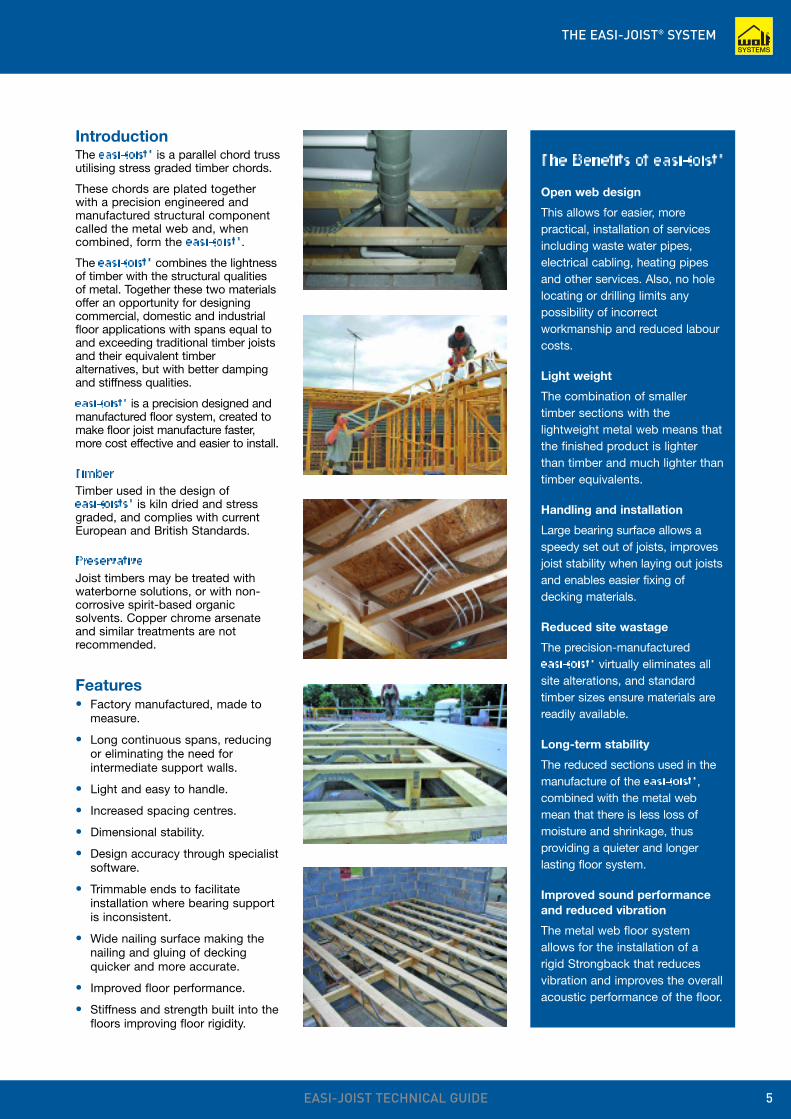
IntroductionThe easi-joist® is a parallel chord trussutilising stress graded timber chords.
These chords are plated togetherwith a precision engineered andmanufactured structural componentcalled the metal web and, whencombined, form the easi-joist®.
The easi-joist® combines the lightnessof timber with the structural qualitiesof metal. Together these two materialsoffer an opportunity for designingcommercial, domestic and industrialfloor applications with spans equal toand exceeding traditional timber joistsand their equivalent timberalternatives, but with better dampingand stiffness qualities.
easi-joist® is a precision designed andmanufactured floor system, created tomake floor joist manufacture faster,more cost effective and easier to install.
TimberTimber used in the design of easi-joists® is kiln dried and stressgraded, and complies with currentEuropean and British Standards.
PreservativeJoist timbers may be treated withwaterborne solutions, or with non-corrosive spirit-based organicsolvents. Copper chrome arsenateand similar treatments are notrecommended.
Features• Factory manufactured, made to
measure.
• Long continuous spans, reducingor eliminating the need forintermediate support walls.
• Light and easy to handle.
• Increased spacing centres.
• Dimensional stability.
• Design accuracy through specialistsoftware.
• Trimmable ends to facilitateinstallation where bearing supportis inconsistent.
• Wide nailing surface making thenailing and gluing of deckingquicker and more accurate.
• Improved floor performance.
• Stiffness and strength built into thefloors improving floor rigidity.
THE EASI-JOIST® SYSTEM
EASI-JOIST TECHNICAL GUIDE6
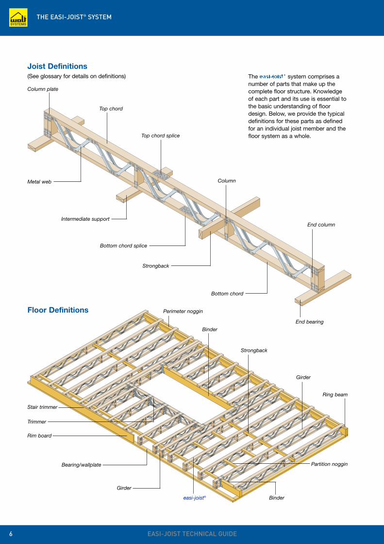
Top chord
Metal web
Bottom chord
Bottom chord splice
Top chord splice
Column
Strongback
Intermediate support
Column plate
End column
End bearing
Joist Definitions(See glossary for details on definitions)
Floor Definitions
Trimmer
Stair trimmer
Binder
Strongback
Perimeter noggin
Girder
Bindereasi-joist®
Girder
Bearing/wallplate Partition noggin
The easi-joist® system comprises anumber of parts that make up thecomplete floor structure. Knowledgeof each part and its use is essential tothe basic understanding of floordesign. Below, we provide the typicaldefinitions for these parts as definedfor an individual joist member and thefloor system as a whole.
Rim board
Ring beam
THE EASI-JOIST® SYSTEM
EASI-JOIST TECHNICAL GUIDE 7
600203
219 (195)
47(35)
(35)
125
47
600211
254
47
160
47
600216
304
47
210
47
768284
417
47
323
47
97
89
84
100
72 97 122
72 97 122
72 97 122
72 97 122
147
147
147
147
Single joist widths WS200
WS250
WS300
WS400
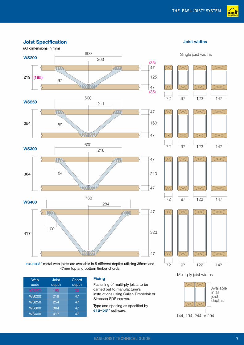
Joist Specification (All dimensions in mm)
easi-joist® metal web joists are available in 5 different depths utilising 35mm and47mm top and bottom timber chords.
Web Joist Chord code depth depth
WS200 195 35
WS200 219 47
WS250 254 47
WS300 304 47
WS400 417 47
Joist widths
FixingFastening of multi-ply joists to becarried out to manufacturer’sinstructions using Cullen Timberlok orSimpson SDS screws.
Type and spacing as specified byeasi-joist® software.
Available in alljoistdepths
Multi-ply joist widths
144, 194, 244 or 294
ACCOMMODATION OF SERVICES
EASI-JOIST TECHNICAL GUIDE8
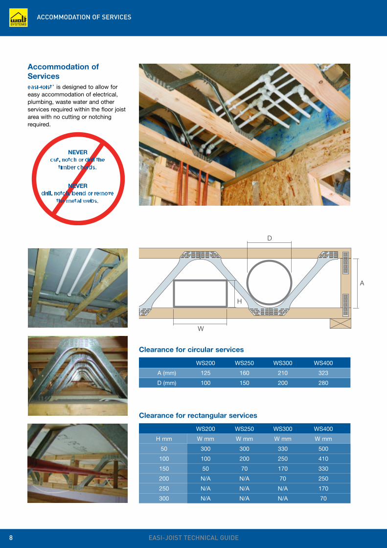
easi-joist® is designed to allow foreasy accommodation of electrical,plumbing, waste water and otherservices required within the floor joistarea with no cutting or notchingrequired.
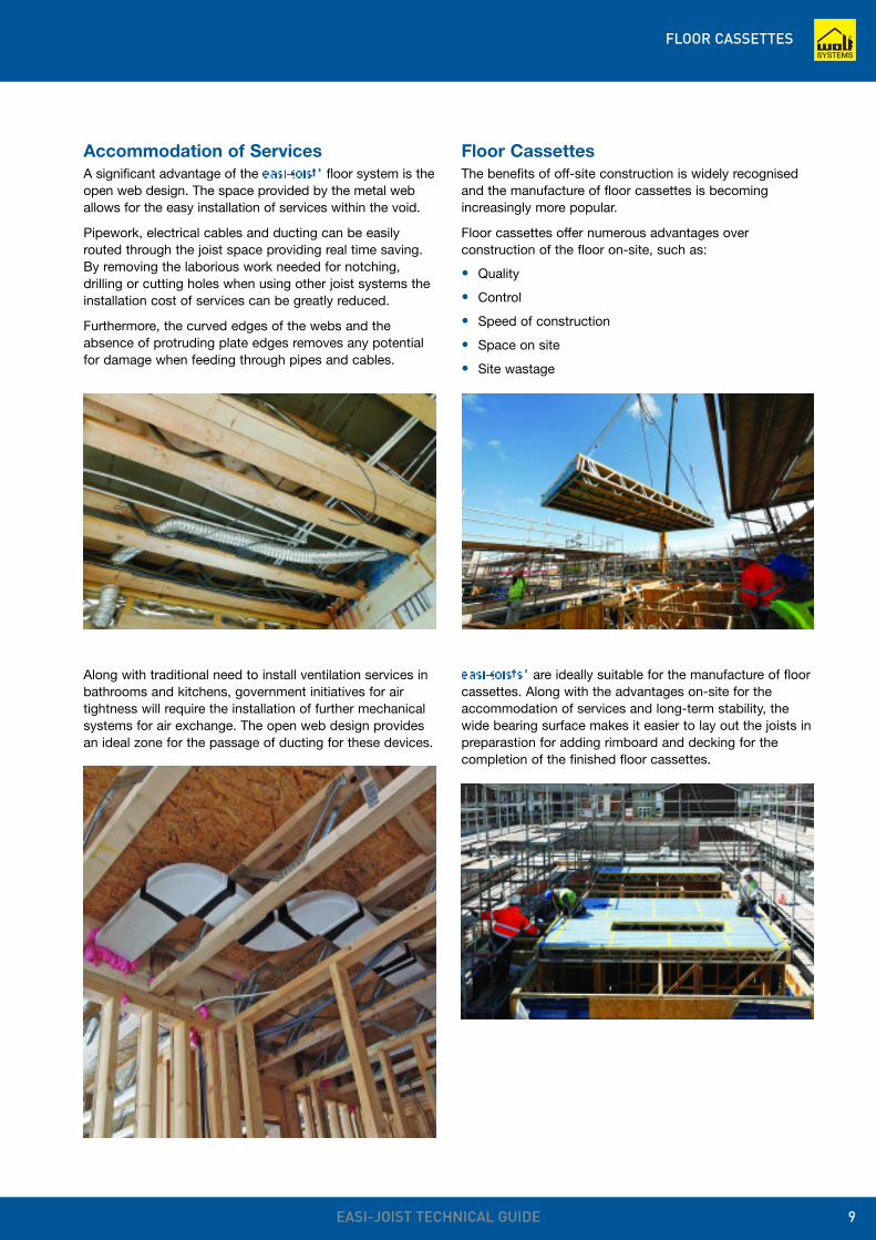
Clearance for rectangular services
WS200 WS250 WS300 WS400
H mm W mm W mm W mm W mm
50 300 300 330 500
100 100 200 250 410
150 50 70 170 330
200 N/A N/A 70 250
250 N/A N/A N/A 170
300 N/A N/A N/A 70
Clearance for circular services
WS200 WS250 WS300 WS400
A (mm) 125 160 210 323
D (mm) 100 150 200 280
D
W
A
H
Accommodation ofServices
NEVERcut, notch or drill the
timber chords.
NEVERdrill, notch, bend or remove
the metal webs.
FLOOR CASSETTES
EASI-JOIST TECHNICAL GUIDE 9
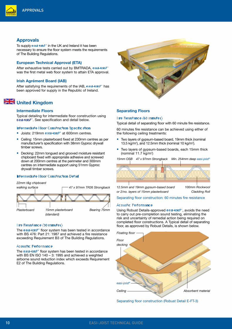
Accommodation of ServicesA significant advantage of the easi-joist® floor system is theopen web design. The space provided by the metal weballows for the easy installation of services within the void.
Pipework, electrical cables and ducting can be easilyrouted through the joist space providing real time saving.By removing the laborious work needed for notching,drilling or cutting holes when using other joist systems theinstallation cost of services can be greatly reduced.
Furthermore, the curved edges of the webs and theabsence of protruding plate edges removes any potentialfor damage when feeding through pipes and cables.
Along with traditional need to install ventilation services inbathrooms and kitchens, government initiatives for airtightness will require the installation of further mechanicalsystems for air exchange. The open web design providesan ideal zone for the passage of ducting for these devices.
Floor CassettesThe benefits of off-site construction is widely recognisedand the manufacture of floor cassettes is becomingincreasingly more popular.
Floor cassettes offer numerous advantages overconstruction of the floor on-site, such as:
• Quality
• Control
• Speed of construction
• Space on site
• Site wastage
easi-joists® are ideally suitable for the manufacture of floorcassettes. Along with the advantages on-site for theaccommodation of services and long-term stability, thewide bearing surface makes it easier to lay out the joists inpreparastion for adding rimboard and decking for thecompletion of the finished floor cassettes.
APPROVALS
EASI-JOIST TECHNICAL GUIDE10
ApprovalsTo supply easi-joist® in the UK and Ireland it has beennecessary to ensure the floor system meets the requirementsof The Building Regulations.
European Technical Approval (ETA)After exhaustive tests carried out by BMTRADA, easi-joist®
was the first metal web floor system to attain ETA approval.
Irish Agrément Board (IAB)After satisfying the requirements of the IAB, easi-joist® hasbeen approved for supply in the Republic of Ireland.
22mm t&g chipboardwalking surface
Separating Floors
Fire Resistance (60 minutes)Typical detail of separating floor with 60 minute fire resistance.
60 minutes fire resistance can be achieved using either ofthe following ceiling treatments:
• Two layers of gypsum-based board, 19mm thick (nominal13.5 kg/m2), and 12.5mm thick (nominal 10 kg/m2).
• Two layers of gypsum-based boards, each 15mm thick (nominal 11.7 kg/m2)
United Kingdom
Intermediate FloorsTypical detailing for intermediate floor construction usingeasi-joist®. See specification and detail below.
Intermediate Floor Construction Specification• Joists: 219mm easi-joist® at 600mm centres.
• Ceiling: 15mm plasterboard fixed at 230mm centres as permanufacturer’s specification with 38mm Gyproc drywalltimber screws.
• Decking: 22mm tongued and grooved moisture resistantchipboard fixed with appropriate adhesive and screweddown at 200mm centres at the perimeter and 300mmcentres on intermediate support using 51mm Gyprocdrywall timber screws.
Separating floor construction (Robust Detail E-FT-3)
15mm plasterboard(standard)
47 x 97mm TR26 Strongback
Bearing 75mmPlasterboard
Floating floor
Floordecking
easi-joist®
Ceiling Absorbent material
15mm OSB
Separating floor construction: 60 minutes fire resistance
47 x 97mm Strongback
12.5mm and 19mm gypsum-based boardor 2/no. layers of 15mm plasterboard
100mm RockwoolCladding Roll
Min. 254mm deep easi-joist®
Intermediate Floor Construction Detail
Acoustic PerformanceUsing Robust Details-approved easi-joist®, avoids the needto carry out pre-completion sound testing, eliminating therisk and uncertainty of remedial action being required oncompleted floor constructions. A Typical detail of separatingfloor, as approved by Robust Details, is shown below.Fire Resistance (30 minutes)
The easi-joist® floor system has been tested in accordancewith BS 476: Part 21: 1987 and achieved a fire resistanceexceeding Requirement B3 of The Building Regulations.
Acoustic PerformanceThe easi-joist® floor system has been tested in accordancewith BS EN ISO 140 – 3: 1995 and achieved a weightedairborne sound reduction index which exceeds RequirementE2 of The Building Regulations.
APPROVALS
EASI-JOIST TECHNICAL GUIDE 11
United Kingdom
Separating Floors (cont)easi-joist® has been officially approved by Robust Details Ltd under detail E-FT-3.This means that easi-joists® used in timber frame flats, constructed as per E-FT-3,will not require pre-completion sound testing to prove compliance with Part E ofthe Building Regulations in England and Wales.
To ensure compliance, it is essential the floor is carefully constructed with specificfloor and ceiling materials. See below for details.
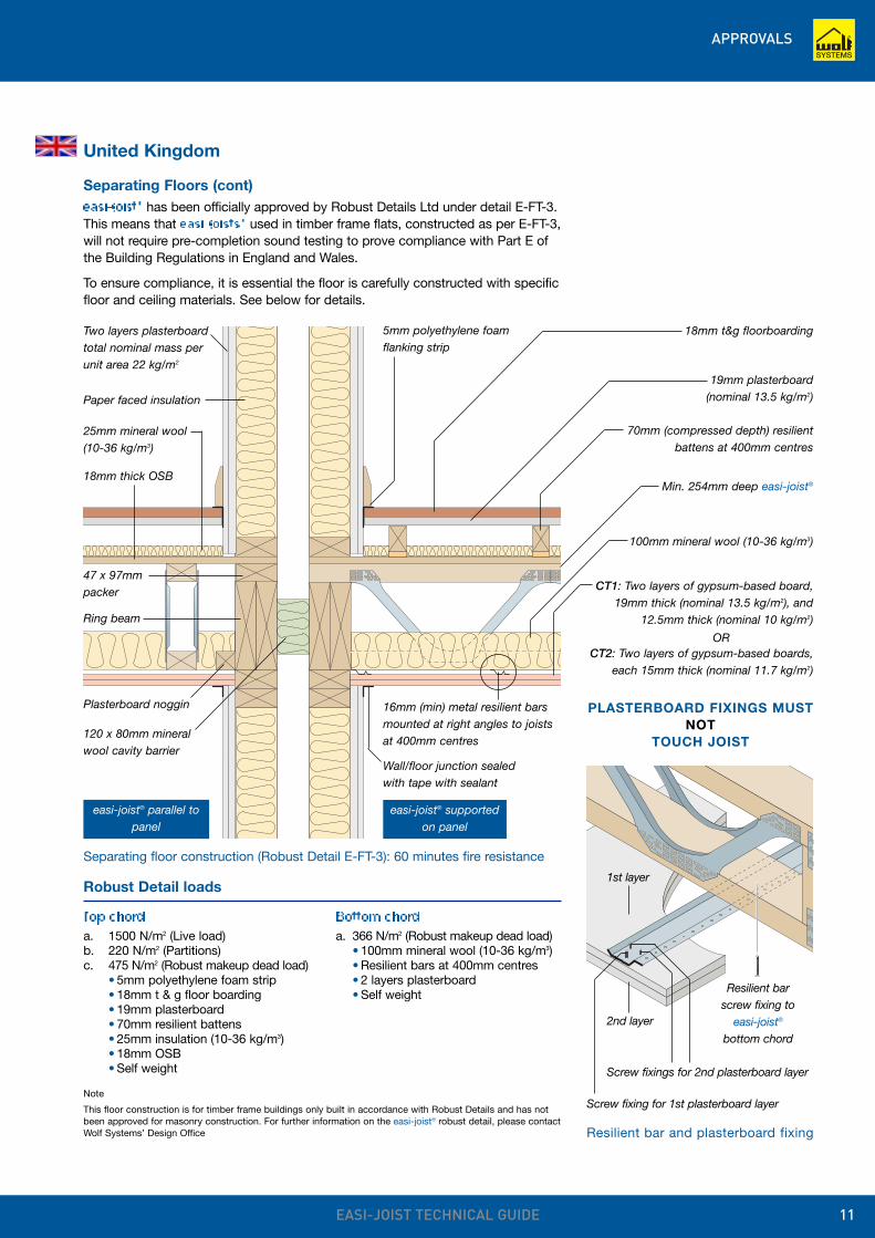
Separating floor construction (Robust Detail E-FT-3): 60 minutes fire resistance
5mm polyethylene foamflanking strip
Two layers plasterboardtotal nominal mass perunit area 22 kg/m2
47 x 97mmpacker
Ring beam
Plasterboard noggin
120 x 80mm mineralwool cavity barrier
18mm t&g floorboarding
19mm plasterboard(nominal 13.5 kg/m2)
70mm (compressed depth) resilientbattens at 400mm centres
100mm mineral wool (10-36 kg/m3)
Wall/floor junction sealedwith tape with sealant
Paper faced insulation
Robust Detail loads
Top chord Bottom chorda. 1500 N/m2 (Live load) a. 366 N/m2 (Robust makeup dead load)b. 220 N/m2 (Partitions) • 100mm mineral wool (10-36 kg/m3)c. 475 N/m2 (Robust makeup dead load) • Resilient bars at 400mm centres
• 5mm polyethylene foam strip • 2 layers plasterboard• 18mm t & g floor boarding • Self weight• 19mm plasterboard• 70mm resilient battens• 25mm insulation (10-36 kg/m3)• 18mm OSB• Self weight
Note
This floor construction is for timber frame buildings only built in accordance with Robust Details and has notbeen approved for masonry construction. For further information on the easi-joist® robust detail, please contactWolf Systems’ Design Office
18mm thick OSB
16mm (min) metal resilient barsmounted at right angles to joistsat 400mm centres
easi-joist® parallel topanel
easi-joist® supportedon panel
CT1: Two layers of gypsum-based board,19mm thick (nominal 13.5 kg/m2), and
12.5mm thick (nominal 10 kg/m2)
CT2: Two layers of gypsum-based boards,each 15mm thick (nominal 11.7 kg/m2)
OR
Resilient bar and plasterboard fixing
25mm mineral wool(10-36 kg/m3)
Min. 254mm deep easi-joist®
PLASTERBOARD FIXINGS MUSTNOT
TOUCH JOIST
Screw fixing for 1st plasterboard layer
Screw fixings for 2nd plasterboard layer
Resilient barscrew fixing to
easi-joist®
bottom chord
1st layer
2nd layer
APPROVALS
EASI-JOIST TECHNICAL GUIDE12
Republic of Ireland
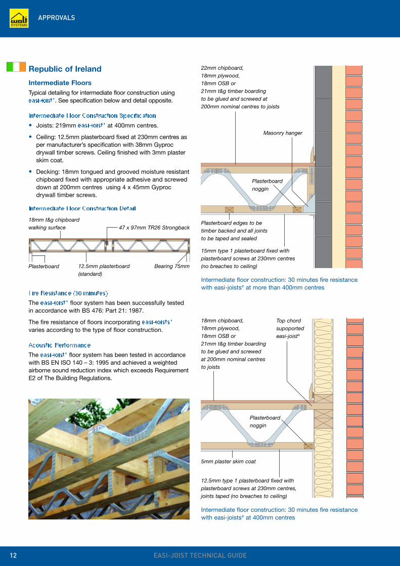
Intermediate FloorsTypical detailing for intermediate floor construction using easi-joist®. See specification below and detail opposite.
Intermediate Floor Construction Specification• Joists: 219mm easi-joist® at 400mm centres.
• Ceiling: 12.5mm plasterboard fixed at 230mm centres asper manufacturer’s specification with 38mm Gyprocdrywall timber screws. Ceiling finished with 3mm plasterskim coat.
• Decking: 18mm tongued and grooved moisture resistantchipboard fixed with appropriate adhesive and screweddown at 200mm centres using 4 x 45mm Gyprocdrywall timber screws.
22mm chipboard,18mm plywood,18mm OSB or21mm t&g timber boardingto be glued and screwed at200mm nominal centres to joists
Intermediate floor construction: 30 minutes fire resistancewith easi-joists® at more than 400mm centres
Intermediate floor construction: 30 minutes fire resistancewith easi-joists® at 400mm centres
15mm type 1 plasterboard fixed withplasterboard screws at 230mm centres(no breaches to ceiling)
Plasterboard edges to betimber backed and all jointsto be taped and sealed
5mm plaster skim coat
Plasterboardnoggin
Masonry hanger
18mm chipboard,18mm plywood,18mm OSB or21mm t&g timber boardingto be glued and screwedat 200mm nominal centresto joists
12.5mm type 1 plasterboard fixed withplasterboard screws at 230mm centres,joints taped (no breaches to ceiling)
Plasterboardnoggin
18mm t&g chipboardwalking surface
12.5mm plasterboard(standard)
47 x 97mm TR26 Strongback
Bearing 75mmPlasterboard
Intermediate Floor Construction Detail
Fire Resistance (30 minutes)The easi-joist® floor system has been successfully testedin accordance with BS 476: Part 21: 1987.
The fire resistance of floors incorporating easi-joists®
varies according to the type of floor construction.
Acoustic PerformanceThe easi-joist® floor system has been tested in accordancewith BS EN ISO 140 – 3: 1995 and achieved a weightedairborne sound reduction index which exceeds RequirementE2 of The Building Regulations.
Top chordsupoportedeasi-joist®
APPROVALS
EASI-JOIST TECHNICAL GUIDE 13
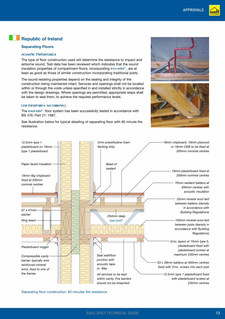
Separating floor construction: 60 minutes fire resistance
5mm polyethylene foamflanking strip
12.5mm type 1plasterboard on 19mmtype 1 plasterboard
97 x 47mmpacker
Ring beam
Plasterboard noggin
Compressible cavitybarrier, typically wirereinforced mineralwool, fixed to one ofthe frames
18mm chipboard, 18mm plywood or 18mm OSB to be fixed at
200mm nominal centres
19mm plasterboard fixed at200mm nominal centres
70mm resilient battens at400mm centres with
acoustic insulation
25mm mineral wool laidbetween battens (density
in accordance withBuilding Regulations)
100mm mineral wool laidbetween joists (density inaccordance with Building
Regulations)
2/no. layers of 15mm type 5,plasterboard fixed withplasterboard screws at
maximum 230mm centres
63 x 38mm battens at 400mm centresfixed with 2/no. screws into each joist
12.5mm type 1 plasterboard fixedwith plasterboard screws at
230mm centres
Seal wall/floorjunction withacoustic tapeor filler
Paper faced insulation
Republic of Ireland
Separating Floors
Acoustic PerformanceThe type of floor construction used will determine the resistance to impact andairborne sound. Test data has been reviewed which indicates that the soundinsulation properties of compartment floors, incorporating easi-joist®, are atleast as good as those of similar construction incorporating traditional joists.
The sound resisting properties depend on the sealing and integrity of theconstruction being maintained intact. Services and openings shall not be locatedwithin or through the voids unless specified in and installed strictly in accordancewith the design drawings. Where openings are permitted, appropriate steps shallbe taken to seal them, to achieve the required performance levels.
Fire Resistance (60 minutes)The easi-joist® floor system has been successfully tested in accordance with BS 476: Part 21: 1987.
See illustration below for typical detailing of separating floor with 60 minute fireresistance.
18mm t&g chipboardfixed at 200mmnominal centres
All services to be keptwithin cavity. Fire barriersshould not be breached
254mm deepeasi-joist®
Bead ofsealant
PROPERTIES AND PERFORMANCE
EASI-JOIST TECHNICAL GUIDE14
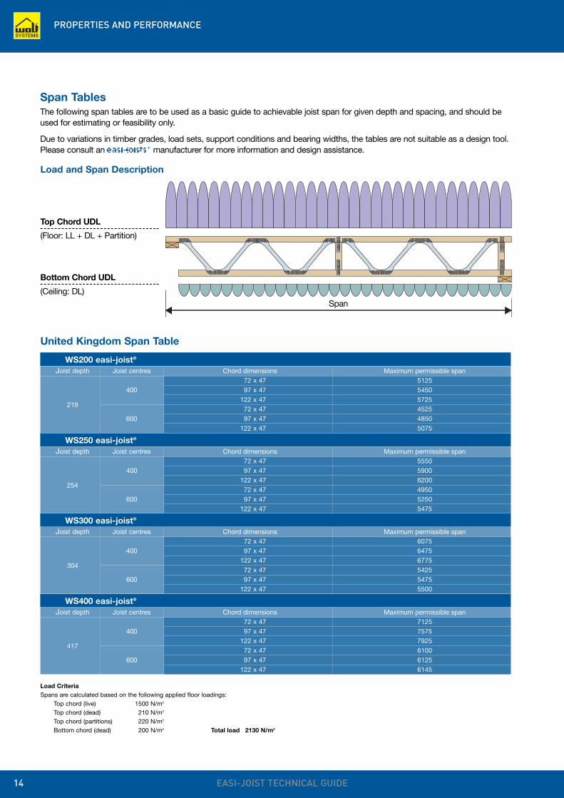
Load CriteriaSpans are calculated based on the following applied floor loadings:
Top chord (live) 1500 N/m2
Top chord (dead) 210 N/m2
Top chord (partitions) 220 N/m2
Bottom chord (dead) 200 N/m2 Total load 2130 N/m2
United Kingdom Span Table
WS200 easi-joist®
Joist depth Joist centres Chord dimensions Maximum permissible span72 x 47 5125
400 97 x 47 5450
219122 x 47 572572 x 47 4525
600 97 x 47 4850122 x 47 5075
Span TablesThe following span tables are to be used as a basic guide to achievable joist span for given depth and spacing, and should beused for estimating or feasibility only.
Due to variations in timber grades, load sets, support conditions and bearing widths, the tables are not suitable as a design tool.Please consult an easi-joists® manufacturer for more information and design assistance.
WS250 easi-joist®
Joist depth Joist centres Chord dimensions Maximum permissible span72 x 47 5550
400 97 x 47 5900
254122 x 47 620072 x 47 4950
600 97 x 47 5250122 x 47 5475
WS300 easi-joist®
Joist depth Joist centres Chord dimensions Maximum permissible span72 x 47 6075
400 97 x 47 6475
304122 x 47 677572 x 47 5425
600 97 x 47 5475122 x 47 5500
WS400 easi-joist®
Joist depth Joist centres Chord dimensions Maximum permissible span72 x 47 7125
400 97 x 47 7575
417122 x 47 792572 x 47 6100
600 97 x 47 6125122 x 47 6145
Load and Span Description
Top Chord UDL
(Floor: LL + DL + Partition)
Bottom Chord UDL
(Ceiling: DL)Span
PROPERTIES AND PERFORMANCE
EASI-JOIST TECHNICAL GUIDE 15
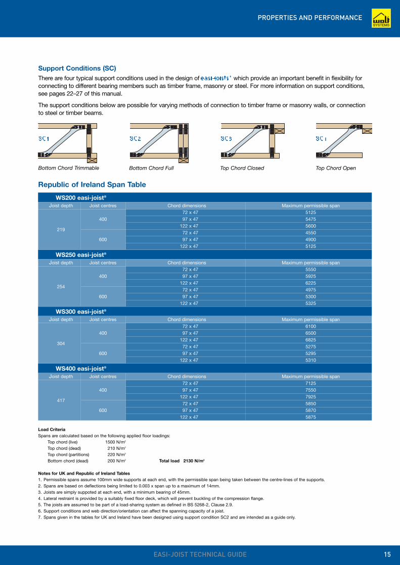
Support Conditions (SC)There are four typical support conditions used in the design of easi-joists® which provide an important benefit in flexibility forconnecting to different bearing members such as timber frame, masonry or steel. For more information on support conditions,see pages 22–27 of this manual.
The support conditions below are possible for varying methods of connection to timber frame or masonry walls, or connectionto steel or timber beams.
Bottom Chord Trimmable Bottom Chord Full Top Chord Closed Top Chord Open
SC1 SC2 SC3 SC4
Load CriteriaSpans are calculated based on the following applied floor loadings:
Top chord (live) 1500 N/m2
Top chord (dead) 210 N/m2
Top chord (partitions) 220 N/m2
Bottom chord (dead) 200 N/m2 Total load 2130 N/m2
Notes for UK and Republic of Ireland Tables1. Permissible spans assume 100mm wide supports at each end, with the permissible span being taken between the centre-lines of the supports.2. Spans are based on deflections being limited to 0.003 x span up to a maximum of 14mm.3. Joists are simply suppoted at each end, with a minimum bearing of 45mm.4. Lateral restraint is provided by a suitably fixed floor deck, which will prevent buckling of the compression flange.5. The joists are assumed to be part of a load-sharing system as defined in BS 5268-2, Clause 2.9.6. Support conditions and web direction/orientation can affect the spanning capacity of a joist.7. Spans given in the tables for UK and Ireland have been designed using support condition SC2 and are intended as a guide only.
Republic of Ireland Span Table
WS200 easi-joist®
Joist depth Joist centres Chord dimensions Maximum permissible span72 x 47 5125
400 97 x 47 5475
219122 x 47 560072 x 47 4550
600 97 x 47 4900122 x 47 5125
WS250 easi-joist®
Joist depth Joist centres Chord dimensions Maximum permissible span72 x 47 5550
400 97 x 47 5925
254122 x 47 622572 x 47 4975
600 97 x 47 5300122 x 47 5325
WS300 easi-joist®
Joist depth Joist centres Chord dimensions Maximum permissible span72 x 47 6100
400 97 x 47 6500
304122 x 47 682572 x 47 5275
600 97 x 47 5295122 x 47 5310
WS400 easi-joist®
Joist depth Joist centres Chord dimensions Maximum permissible span72 x 47 7125
400 97 x 47 7550
417122 x 47 792572 x 47 5850
600 97 x 47 5870122 x 47 5875
STRONGBACKS AND RESTRAINT STRAPS
EASI-JOIST TECHNICAL GUIDE16
easi-joist® Strongback size Alternate StrongbackNominal Size TR26 Grade Lower Grade
WS200 35 x 72 TR26 35 x 97 C16
WS250 35 x 97 TR26 35 x 122 C16
WS300 35 x 122 TR26 35 x 142 C16
WS400 35 x 147 TR26 35 x 172 C16
300mm
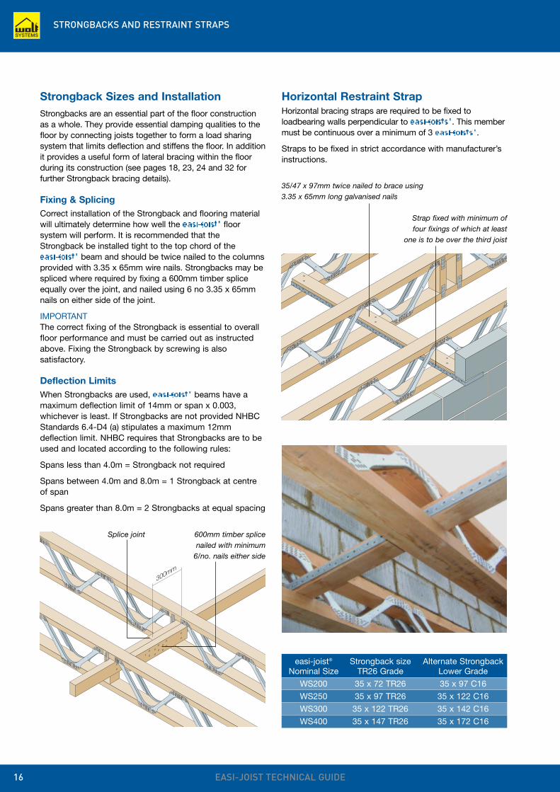
Strap fixed with minimum offour fixings of which at least
one is to be over the third joist
Horizontal Restraint StrapHorizontal bracing straps are required to be fixed toloadbearing walls perpendicular to easi-joists®. This membermust be continuous over a minimum of 3 easi-joists®.
Straps to be fixed in strict accordance with manufacturer’sinstructions.
Strongback Sizes and InstallationStrongbacks are an essential part of the floor constructionas a whole. They provide essential damping qualities to thefloor by connecting joists together to form a load sharingsystem that limits deflection and stiffens the floor. In additionit provides a useful form of lateral bracing within the floorduring its construction (see pages 18, 23, 24 and 32 forfurther Strongback bracing details).
Fixing & SplicingCorrect installation of the Strongback and flooring materialwill ultimately determine how well the easi-joist® floorsystem will perform. It is recommended that theStrongback be installed tight to the top chord of the easi-joist® beam and should be twice nailed to the columnsprovided with 3.35 x 65mm wire nails. Strongbacks may bespliced where required by fixing a 600mm timber spliceequally over the joint, and nailed using 6 no 3.35 x 65mmnails on either side of the joint.
IMPORTANTThe correct fixing of the Strongback is essential to overallfloor performance and must be carried out as instructedabove. Fixing the Strongback by screwing is alsosatisfactory.
Deflection LimitsWhen Strongbacks are used, easi-joist® beams have amaximum deflection limit of 14mm or span x 0.003,whichever is least. If Strongbacks are not provided NHBCStandards 6.4-D4 (a) stipulates a maximum 12mmdeflection limit. NHBC requires that Strongbacks are to beused and located according to the following rules:
Spans less than 4.0m = Strongback not required
Spans between 4.0m and 8.0m = 1 Strongback at centreof span
Spans greater than 8.0m = 2 Strongbacks at equal spacing
Splice joint
35/47 x 97mm twice nailed to brace using3.35 x 65mm long galvanised nails
600mm timber splicenailed with minimum
6/no. nails either side
GROUND FLOOR JOISTS
EASI-JOIST TECHNICAL GUIDE 17
Suspended Ground FloorsWhen designing and installing easi-joists® at ground floor level, thefollowing points should be considered.
Ground floor suspended floors areclassified as Service Class 2 andtherefore will have an increasedmoisture content.
Adequate provision should be madefor ventilation of the void below thejoists which must be maintained at aminimum of 150mm deep and complywith Building Regulations.
The absence of a ceiling coveringresults in the bottom chord of the easi-joist® having no lateral restraint.Therefore noggins must be installedalong intermediate supports to preventbuckling where the bottom chord willbe in compression.
Deflection limits may be reduced toaccount for the reduced stiffness of thefloor compared to floors fitted with aceiling diaphragm.
Large appliances such as washingmachines or spin dryers may producedynamic movement requiring morestringent deflection limits.
Induced dynamic movement will bereduced by using a discontinuous joistlayout between separate ground floorrooms.
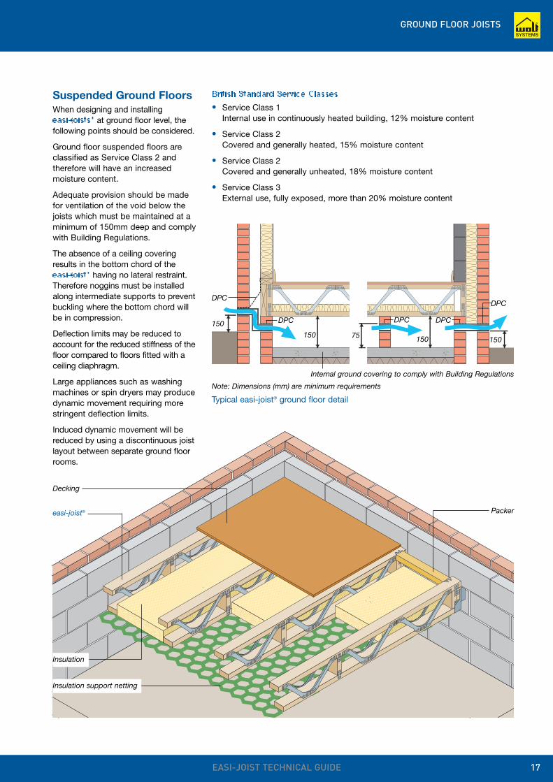
Decking
Insulation support netting
Insulation
Packereasi-joist®
Typical easi-joist® ground floor detail
British Standard Service Classes• Service Class 1
Internal use in continuously heated building, 12% moisture content
• Service Class 2Covered and generally heated, 15% moisture content
• Service Class 2Covered and generally unheated, 18% moisture content
• Service Class 3External use, fully exposed, more than 20% moisture content
Internal ground covering to comply with Building Regulations
DPC
DPC DPC
DPC
150
150 75150150
DPC
Note: Dimensions (mm) are minimum requirements
FLOOR DESIGN FACTORS
EASI-JOIST TECHNICAL GUIDE18
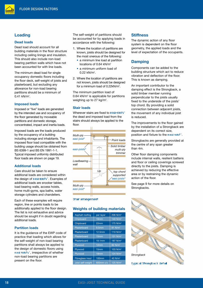
Strongback
Loading
Dead loadsDead load should account for allbuilding materials in the floor structureincluding ceiling linings and insulation.This should also include non-loadbearing partition walls which have notbeen accounted for with line loads.
The minimum dead load for singleoccupancy domestic floors includingthe floor deck, self-weight of joists andplasterboard, but excluding anyallowance for non-load bearingpartitions should be a minimum of0.41 kN/m2.
Imposed loadsImposed or “live” loads are generatedby the intended use and occupancy ofthe floor generated by moveablepartitions and domestic storage,concentrated, impact and inertia loads.
Imposed loads are the loads producedby the occupancy of a buildingincluding storage and inhabitants. Theimposed floor load compatible with thebuilding usage should be obtained fromBS 6399-1 and BS EN 1991-1-1.Typical imposed uniformly distributedfloor loads are shown on page 19.
Additional loadsCare should be taken to ensureadditional loads are considered withinthe design of easi-joists®. Examples ofadditional loads are snooker tables,load bearing walls, access hoists,home multi-gyms, spa baths, waterstorage cylinders and chandeliers.
Each of these examples will requireregion, line or points loads to beadditionally applied to the floor design.The list is not exhaustive and adviceshould be sought if in doubt regardingadditional loads.
Partition loadsIt is the guidance of the EWP code ofpractice that loading which allows forthe self-weight of non-load bearingpartitions shall always be applied tothe design of domestic floors usingeasi-joists®, irrespective of whethernon-load bearing partitions arepresent on the floor.
StiffnessThe dynamic action of any floorsystem is dependent on the floorgeometry, the applied loads and thelevel of expectation of the occupants.
DampingComponents can be added to thebuilding structure which act to reducevibration and deflection of the floor.This is known as damping.
An important contributor to thedamping effect is the Strongback, asolid timber member runningperpendicular to the joists usuallyfixed to the underside of the joists’top chord. By providing a solidconnection between adjacent joists,the movement of any individual joistis reduced.
The improvements to the floor gainedby the installation of a Strongback aredependent on its correct size,position and fixture to the easi-joist®.
Strongbacks are generally provided atthe centre of any span greater than 4m.
Other floor damping componentsinclude internal walls, resilient battensand floor or ceiling coverings screweddirectly to the joists. Damping isachieved by reducing the effectivearea or by restraining the dynamicaction of the floor.
See page 9 for more details onStrongbacks.
Asphalt roofing per layer 206 N/m2
Chipboard 18mm 140 N/m2
Chipboard 22mm 175 N/m2
Plasterboard 9.5mm 81 N/m2
Plasterboard 12.5mm 110 N/m2
Plasterboard 15mm 131 N/m2
Plasterboard 19.1mm 187 N/m2
Plywood 12mm 82 N/m2
Plywood 15mm 103 N/m2
Plywood 18mm 124 N/m2
Fibreglass insul 100mm 40 N/m2
Joist self-weight 600mm c/c 125 N/m2
Weights of building materials
The self-weight of partitions shouldbe accounted for by applying loads inaccordance with the following:
1. Where the location of partitions areknown, joists should be designed forthe most onerous of the following: • a minimum line load at partition
locations of 0.64 kN/m2
• a minimum uniform load of 0.22 kN/m2.
2. Where the location of partitions arenot known, joists should be designedfor a minimum load of 0.22kN/m2.
The minimum partition load of 0.64 kN/m2 is applicable for partitionsweighing up to 27 kg/m2.
Stair loadsWherever stairs are fixed to easi-joists®
the dead and imposed load from thestairs should always be applied to thefloor.
Typical Strongback detail
Point loads
Multi-plyeasi-joist®
top chordsupportedeasi-joists®
Loadbearingwall
Solid timbermulti-plytrimmer
easi-joists®
Stair arrangement
Up
Multi-plyeasi-joist®
FLOOR DESIGN FACTORS
EASI-JOIST TECHNICAL GUIDE 19
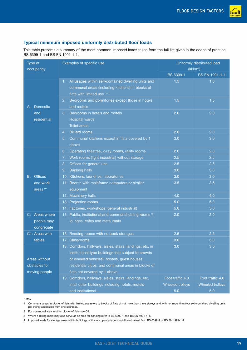
Typical minimum imposed uniformly distributed floor loads
This table presents a summary of the most common imposed loads taken from the full list given in the codes of practiceBS 6399-1 and BS EN 1991-1-1.
Type of Examples of specific use Uniformly distributed load
occupancy (kN/m2)
BS 6399-1 BS EN 1991-1-1
1. All usages within self-contained dwelling units and 1.5 1.5
communal areas (including kitchens) in blocks of
flats with limited use (1, 2)
2. Bedrooms and dormitories except those in hotels 1.5 1.5
A: Domestic and motels
and 3. Bedrooms in hotels and motels 2.0 2.0
residential Hospital wards
Toilet areas
4. Billiard rooms 2.0 2.0
5. Communal kitchens except in flats covered by 1 3.0 3.0
above
6. Operating theatres, x-ray rooms, utility rooms 2.0 2.0
7. Work rooms (light industrial) without storage 2.5 2.5
8. Offices for general use 2.5 2.5
9. Banking halls 3.0 3.0
B: Offices 10. KItchens, laundries, laboratories 3.0 3.0
and work 11. Rooms with mainframe computers or similar 3.5 3.5
areas (4) equipment
12. Machinery halls 4.0 4.0
13. Projection rooms 5.0 5.0
14. Factories, workshops (general industrial) 5.0 5.0
C: Areas where 15. Public, institutional and communal dining rooms (3), 2.0 2.0
people may lounges, cafes and restaurants
congregate
C1: Areas with 16. Reading rooms with no book storages 2.5 2.5
tables 17. Classrooms 3.0 3.0
18. Corridors, hallways, aisles, stairs, landings, etc. in 3.0 3.0
institutional type buildings (not subject to crowds
Areas without or wheeled vehicles), hostels, guest houses,
obstacles for residential clubs, and communal areas in blocks of
moving people flats not covered by 1 above
19. Corridors, hallways, aisles, stairs, landings, etc. Foot traffic 4.0 Foot traffic 4.0
in all other buildings including hotels, motels Wheeled trolleys Wheeled trolleys
and institutional 5.0 5.0
Notes
1 Communal areas in blocks of flats with limited use refers to blocks of flats of not more than three storeys and with not more than four self-contained dwelling units per storey accessible from one staircase.
2 For communal area in other blocks of flats see C3.
3 Where a dining room may also serve as an area for dancing refer to BS 6399-1 and BS EN 1991-1-1.
4 Imposed loads for storage areas within buildings of this occupancy type should be obtained from BS 6399-1 or BS EN 1991-1-1.
FLOOR DETAILING KEY
EASI-JOIST TECHNICAL GUIDE20
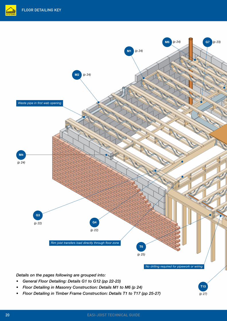
Details on the pages following are grouped into:
• General Floor Detailing: Details G1 to G12 (pp 22-23)
• Floor Detailing in Masonry Construction: Details M1 to M6 (p 24)
• Floor Detailing in Timber Frame Construction: Details T1 to T17 (pp 25-27)
M1
M2
M4
G3
G4
T6
T13
G7M6
Waste pipe in first web opening
Rim joist transfers load directly through floor zone
No drilling required for pipework or wiring
(p 24)
(p 24)
(p 24)
(p 24)
(p 22)
(p 22)
(p 25)
(p 27)
(p 23)
FLOOR DETAILING KEY
EASI-JOIST TECHNICAL GUIDE 21
G6
T17
T8
G8
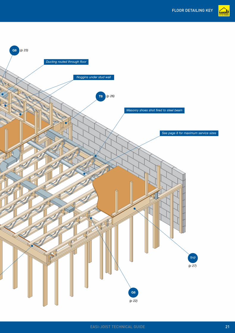
Ducting routed through floor
Noggins under stud wall
Masonry shoes shot fired to steel beam
See page 8 for maximum service sizes
(p 22)
(p 23)
(p 26)
(p 27)
GENERAL FLOOR DETAILING
EASI-JOIST TECHNICAL GUIDE22
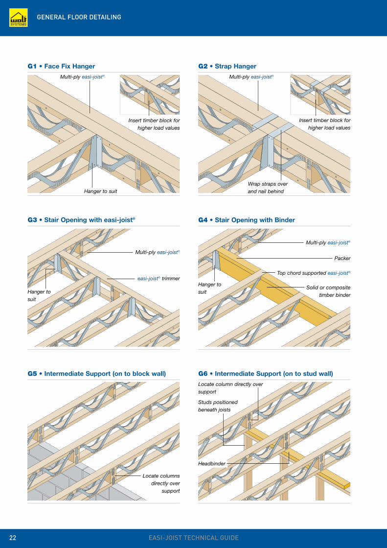
G1 • Face Fix Hanger G2 • Strap Hanger
Insert timber block forhigher load values
Insert timber block forhigher load values
Wrap straps overand nail behind
Studs positionedbeneath joists
Locate column directly oversupport
Locate columnsdirectly over
support
G3 • Stair Opening with easi-joist®
easi-joist® trimmer
G5 • Intermediate Support (on to block wall) G6 • Intermediate Support (on to stud wall)
G4 • Stair Opening with Binder
Packer
Top chord supported easi-joist®
Solid or compositetimber binder
Hanger tosuit
Multi-ply easi-joist®
Multi-ply easi-joist®
Hanger tosuit
Multi-ply easi-joist® Multi-ply easi-joist®
Hanger to suit
Headbinder
GENERAL FLOOR DETAILING
EASI-JOIST TECHNICAL GUIDE 23
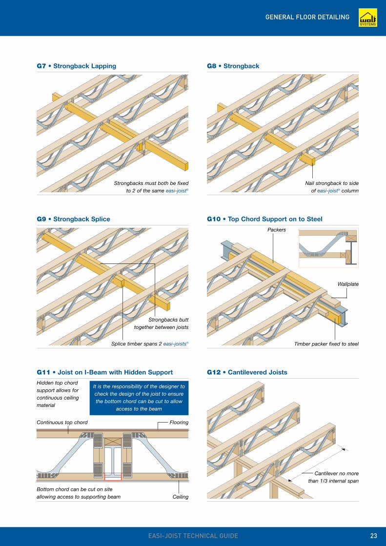
G7 • Strongback Lapping
Strongbacks must both be fixedto 2 of the same easi-joist®
G8 • Strongback
Nail strongback to sideof easi-joist® column
G9 • Strongback Splice
Strongbacks butttogether between joists
Splice timber spans 2 easi-joists®
G10 • Top Chord Support on to Steel
Packers
Wallplate
Timber packer fixed to steel
G11 • Joist on I-Beam with Hidden Support
Hidden top chordsupport allows forcontinuous ceilingmaterial
Continuous top chord Flooring
Bottom chord can be cut on siteallowing access to supporting beam
It is the responsibility of the designer tocheck the design of the joist to ensurethe bottom chord can be cut to allow
access to the beam
Ceiling
G12 • Cantilevered Joists
Cantilever no morethan 1/3 internal span
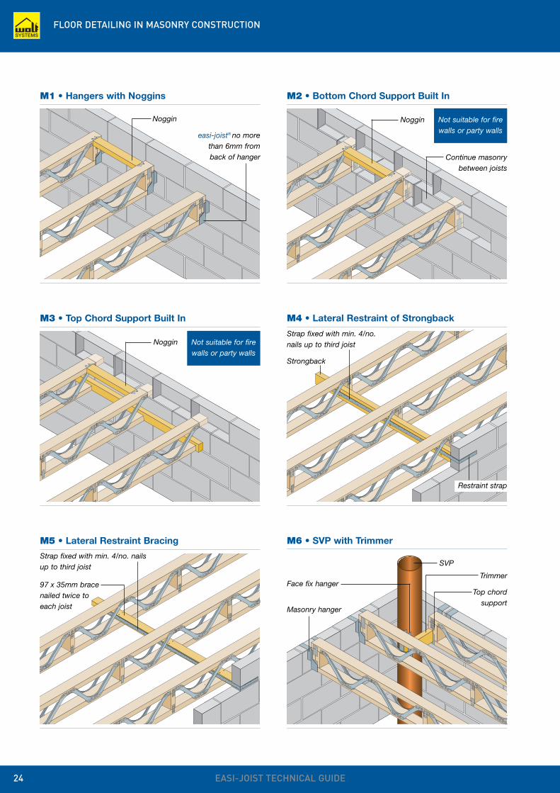
FLOOR DETAILING IN MASONRY CONSTRUCTION
EASI-JOIST TECHNICAL GUIDE24
easi-joist® no morethan 6mm fromback of hanger
M1 • Hangers with Noggins
Noggin Not suitable for firewalls or party walls
M2 • Bottom Chord Support Built In
Noggin
Not suitable for firewalls or party walls
M3 • Top Chord Support Built In
Noggin
Continue masonrybetween joists
M4 • Lateral Restraint of Strongback
Strap fixed with min. 4/no.nails up to third joist
Strongback
M5 • Lateral Restraint Bracing
Strap fixed with min. 4/no. nailsup to third joist
97 x 35mm bracenailed twice toeach joist
M6 • SVP with Trimmer
Masonry hanger
Face fix hanger
SVP
Trimmer
Top chordsupport
Restraint strap
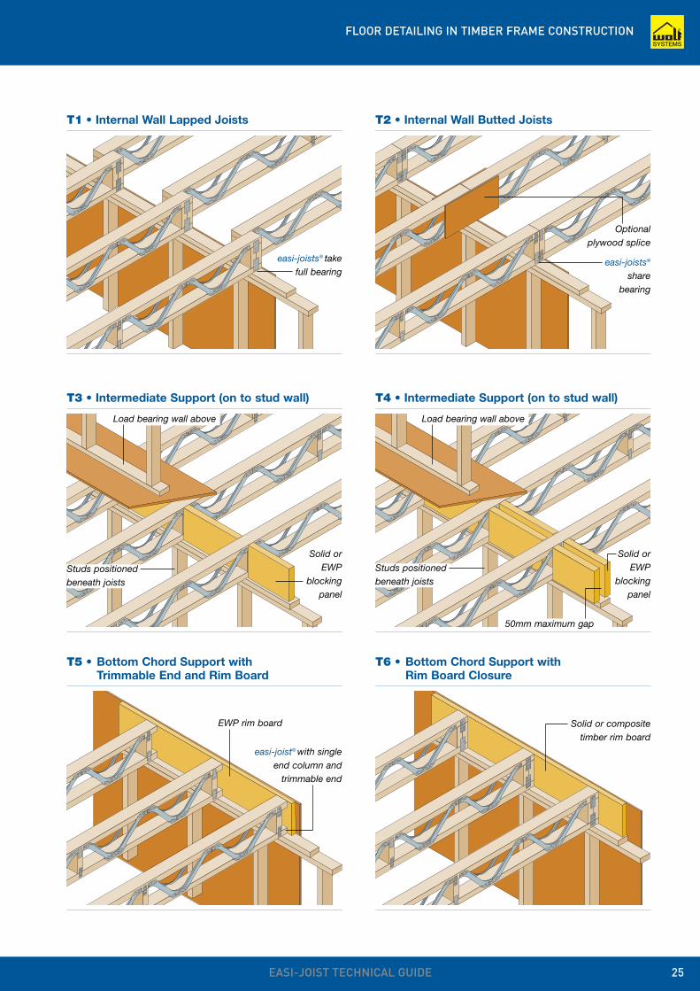
FLOOR DETAILING IN TIMBER FRAME CONSTRUCTION
EASI-JOIST TECHNICAL GUIDE 25
easi-joists® takefull bearing
T1 • Internal Wall Lapped Joists
Optionalplywood splice
T2 • Internal Wall Butted Joists
easi-joists®
sharebearing
Solid orEWP
blockingpanel
T3 • Intermediate Support (on to stud wall)
Load bearing wall above
Solid orEWP
blockingpanel
T4 • Intermediate Support (on to stud wall)
Load bearing wall above
50mm maximum gap
Studs positionedbeneath joists
Studs positionedbeneath joists
T5 • Bottom Chord Support with Trimmable End and Rim Board
EWP rim board
T6 • Bottom Chord Support with Rim Board Closure
Solid or compositetimber rim board
easi-joist® with singleend column and
trimmable end
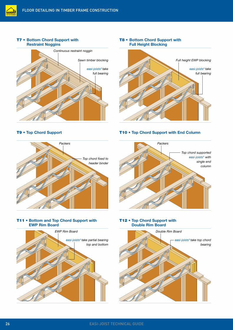
FLOOR DETAILING IN TIMBER FRAME CONSTRUCTION
EASI-JOIST TECHNICAL GUIDE26
T7 • Bottom Chord Support with Restraint Noggins
Sawn timber blocking
easi-joists® takefull bearing
Continuous restraint noggin
T8 • Bottom Chord Support with Full Height Blocking
Full height EWP blocking
easi-joists® takefull bearing
T9 • Top Chord Support
Packers
Top chord fixed toheader binder
T10 • Top Chord Support with End Column
T11 • Bottom and Top Chord Support with EWP Rim Board
EWP Rim Board
easi-joists® take partial bearingtop and bottom
T12 • Top Chord Support with Double Rim Board
Double Rim Board
easi-joists® take top chordbearing
Packers
Top chord supportedeasi-joists® with
single end column
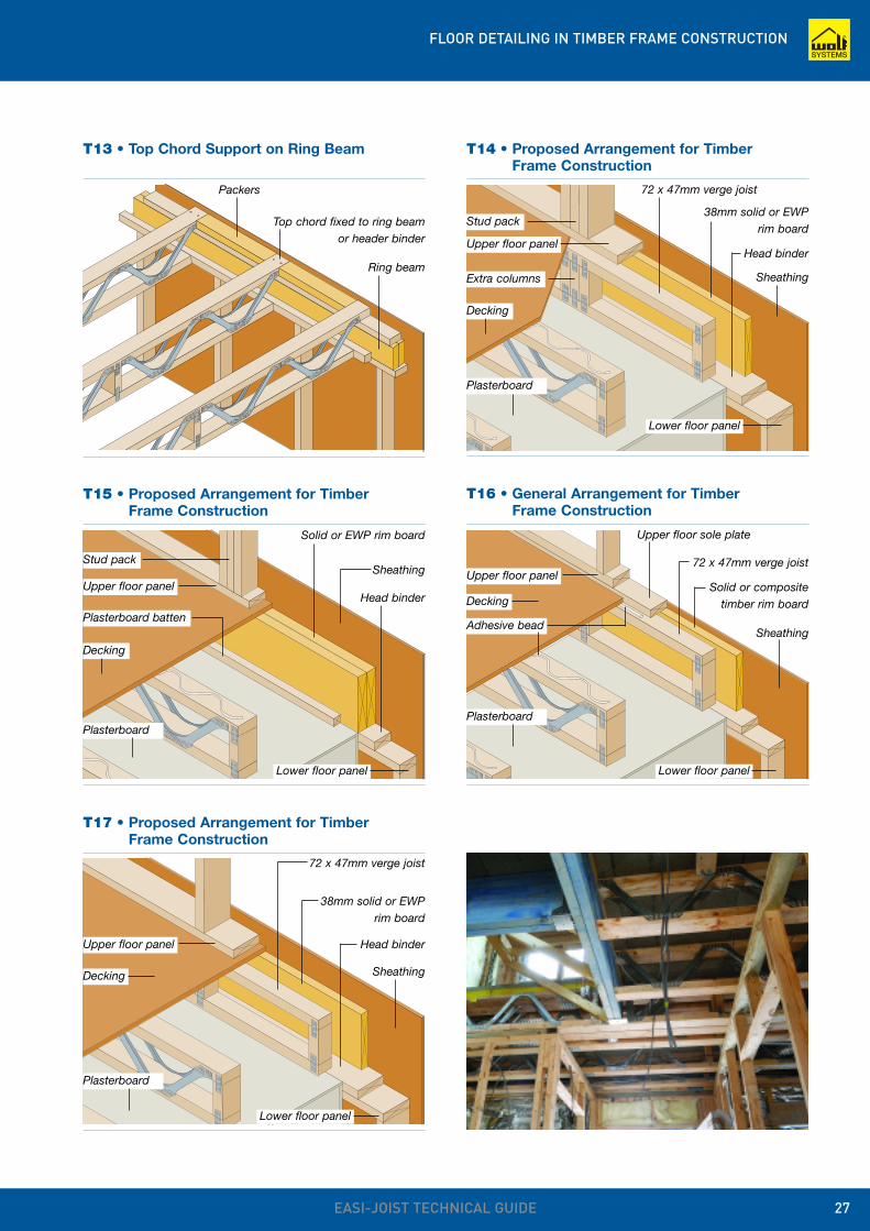
FLOOR DETAILING IN TIMBER FRAME CONSTRUCTION
EASI-JOIST TECHNICAL GUIDE 27
T13 • Top Chord Support on Ring Beam
Packers
Top chord fixed to ring beamor header binder
Ring beam
T14 • Proposed Arrangement for Timber Frame Construction
72 x 47mm verge joist
Sheathing
38mm solid or EWPrim board
Head binder
Lower floor panel
Stud pack
Extra columns
Decking
Plasterboard
T15 • Proposed Arrangement for Timber Frame Construction
Sheathing
Solid or EWP rim board
Head binder
Plasterboard batten
T16 • General Arrangement for Timber Frame Construction
72 x 47mm verge joist
Sheathing
Solid or compositetimber rim board
T17 • Proposed Arrangement for Timber Frame Construction
72 x 47mm verge joist
Sheathing
38mm solid or EWPrim board
Head binder
Upper floor panel
Upper floor panel
Stud pack
Decking
Plasterboard
Lower floor panel
Decking
Upper floor panel
Upper floor sole plate
Plasterboard
Adhesive bead
Lower floor panel
Decking
Plasterboard
Upper floor panel
Lower floor panel
METALWORK
EASI-JOIST TECHNICAL GUIDE28
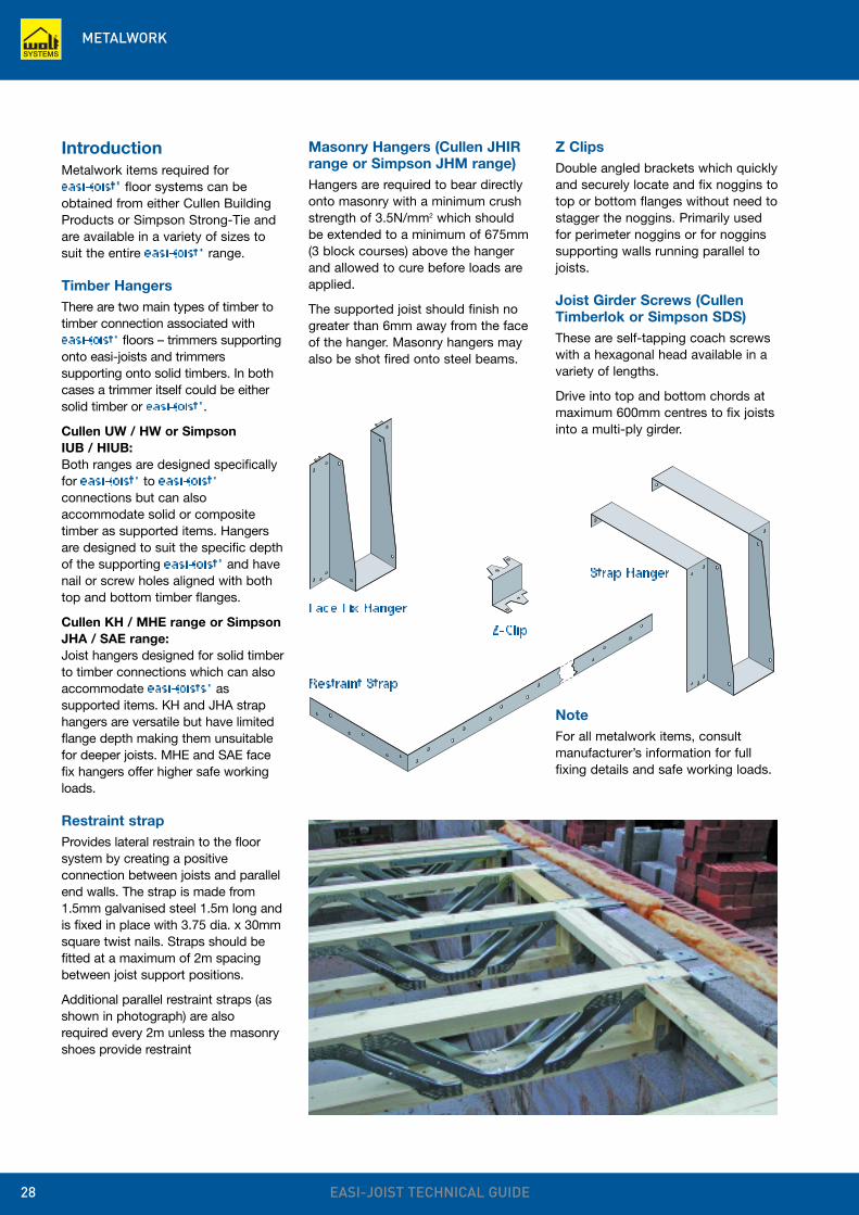
IntroductionMetalwork items required for easi-joist® floor systems can beobtained from either Cullen BuildingProducts or Simpson Strong-Tie andare available in a variety of sizes tosuit the entire easi-joist® range.
Timber HangersThere are two main types of timber totimber connection associated witheasi-joist® floors – trimmers supportingonto easi-joists and trimmerssupporting onto solid timbers. In bothcases a trimmer itself could be eithersolid timber or easi-joist®.
Cullen UW / HW or Simpson IUB / HIUB:Both ranges are designed specificallyfor easi-joist® to easi-joist®
connections but can alsoaccommodate solid or compositetimber as supported items. Hangersare designed to suit the specific depthof the supporting easi-joist® and havenail or screw holes aligned with bothtop and bottom timber flanges.
Cullen KH / MHE range or SimpsonJHA / SAE range:Joist hangers designed for solid timberto timber connections which can alsoaccommodate easi-joists® assupported items. KH and JHA straphangers are versatile but have limitedflange depth making them unsuitablefor deeper joists. MHE and SAE facefix hangers offer higher safe workingloads.
Restraint strapProvides lateral restrain to the floorsystem by creating a positiveconnection between joists and parallelend walls. The strap is made from1.5mm galvanised steel 1.5m long andis fixed in place with 3.75 dia. x 30mmsquare twist nails. Straps should befitted at a maximum of 2m spacingbetween joist support positions.
Additional parallel restraint straps (asshown in photograph) are alsorequired every 2m unless the masonryshoes provide restraint
Masonry Hangers (Cullen JHIRrange or Simpson JHM range)Hangers are required to bear directlyonto masonry with a minimum crushstrength of 3.5N/mm2 which shouldbe extended to a minimum of 675mm(3 block courses) above the hangerand allowed to cure before loads areapplied.
The supported joist should finish nogreater than 6mm away from the faceof the hanger. Masonry hangers mayalso be shot fired onto steel beams.
Z ClipsDouble angled brackets which quicklyand securely locate and fix noggins totop or bottom flanges without need tostagger the noggins. Primarily usedfor perimeter noggins or for nogginssupporting walls running parallel tojoists.
Joist Girder Screws (CullenTimberlok or Simpson SDS)These are self-tapping coach screwswith a hexagonal head available in avariety of lengths.
Drive into top and bottom chords atmaximum 600mm centres to fix joistsinto a multi-ply girder.
Face Fix HangerZ-Clip
Strap Hanger
Restraint StrapNoteFor all metalwork items, consultmanufacturer’s information for fullfixing details and safe working loads.
ROOF DETAILING
EASI-JOIST TECHNICAL GUIDE 29
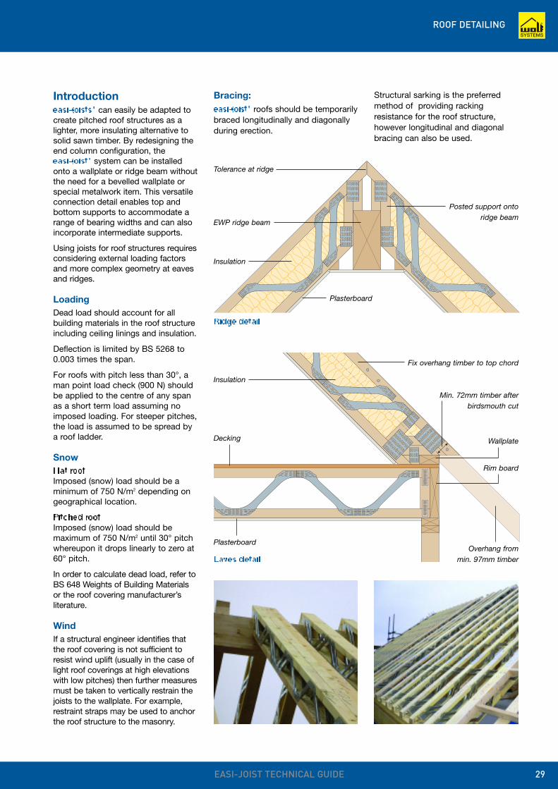
Tolerance at ridge
Ridge detail
Introduction easi-joists® can easily be adapted tocreate pitched roof structures as alighter, more insulating alternative tosolid sawn timber. By redesigning theend column configuration, the easi-joist® system can be installedonto a wallplate or ridge beam withoutthe need for a bevelled wallplate orspecial metalwork item. This versatileconnection detail enables top andbottom supports to accommodate arange of bearing widths and can alsoincorporate intermediate supports.
Using joists for roof structures requiresconsidering external loading factorsand more complex geometry at eavesand ridges.
LoadingDead load should account for allbuilding materials in the roof structureincluding ceiling linings and insulation.
Deflection is limited by BS 5268 to0.003 times the span.
For roofs with pitch less than 30°, aman point load check (900 N) shouldbe applied to the centre of any spanas a short term load assuming noimposed loading. For steeper pitches,the load is assumed to be spread bya roof ladder.
SnowFlat roofImposed (snow) load should be aminimum of 750 N/m2 depending ongeographical location.
Pitched roofImposed (snow) load should bemaximum of 750 N/m2 until 30° pitchwhereupon it drops linearly to zero at60° pitch.
In order to calculate dead load, refer toBS 648 Weights of Building Materialsor the roof covering manufacturer’sliterature.
WindIf a structural engineer identifies thatthe roof covering is not sufficient toresist wind uplift (usually in the case oflight roof coverings at high elevationswith low pitches) then further measuresmust be taken to vertically restrain thejoists to the wallplate. For example,restraint straps may be used to anchorthe roof structure to the masonry.
Bracing:easi-joist® roofs should be temporarilybraced longitudinally and diagonallyduring erection.
Eaves detail
Insulation
Plasterboard
EWP ridge beam
Posted support ontoridge beam
Fix overhang timber to top chord
Insulation
Plasterboard
Min. 72mm timber afterbirdsmouth cut
Rim board
Overhang frommin. 97mm timber
Decking Wallplate
Structural sarking is the preferredmethod of providing rackingresistance for the roof structure,however longitudinal and diagonalbracing can also be used.
NOTES ON INSTALLATION
EASI-JOIST TECHNICAL GUIDE30
3
7
7
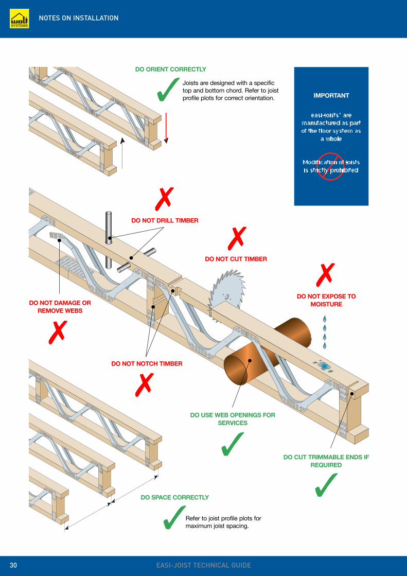
DO NOT DRILL TIMBER
DO NOT CUT TIMBER
DO NOT EXPOSE TOMOISTUREDO NOT DAMAGE OR
REMOVE WEBS
DO NOT NOTCH TIMBER
DO USE WEB OPENINGS FORSERVICES
3
77
7
DO CUT TRIMMABLE ENDS IFREQUIRED
DO ORIENT CORRECTLY
DO SPACE CORRECTLY
3
3
Joists are designed with a specifictop and bottom chord. Refer to joistprofile plots for correct orientation.
Refer to joist profile plots formaximum joist spacing.
IMPORTANT
easi-joists® aremanufactured as partof the floor system as
a whole
Modification of joistsis strictly prohibited
HEALTH AND SAFETY
EASI-JOIST TECHNICAL GUIDE 31
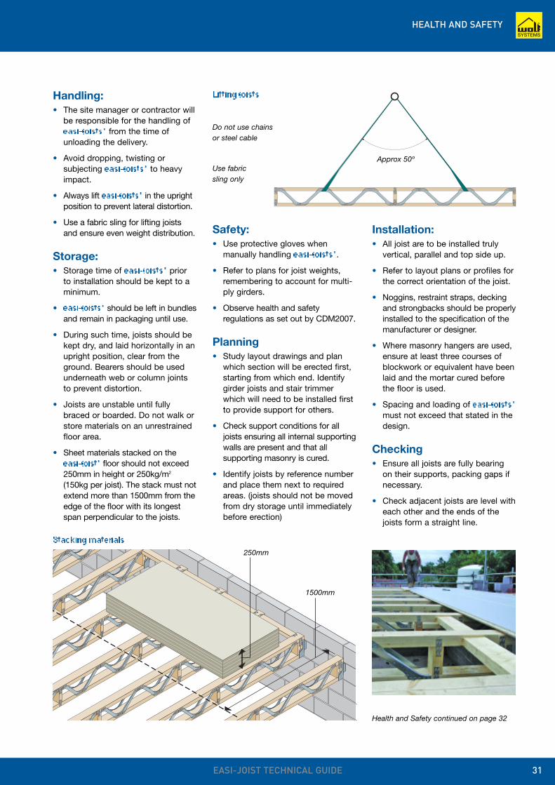
Handling:• The site manager or contractor will
be responsible for the handling ofeasi-joists® from the time ofunloading the delivery.
• Avoid dropping, twisting orsubjecting easi-joists® to heavyimpact.
• Always lift easi-joists® in the uprightposition to prevent lateral distortion.
• Use a fabric sling for lifting joistsand ensure even weight distribution.
Storage:• Storage time of easi-joists® prior
to installation should be kept to aminimum.
• easi-joists® should be left in bundlesand remain in packaging until use.
• During such time, joists should bekept dry, and laid horizontally in anupright position, clear from theground. Bearers should be usedunderneath web or column jointsto prevent distortion.
• Joists are unstable until fullybraced or boarded. Do not walk orstore materials on an unrestrainedfloor area.
• Sheet materials stacked on theeasi-joist® floor should not exceed250mm in height or 250kg/m2
(150kg per joist). The stack must notextend more than 1500mm from theedge of the floor with its longestspan perpendicular to the joists.
Safety:• Use protective gloves when
manually handling easi-joists®.
• Refer to plans for joist weights,remembering to account for multi-ply girders.
• Observe health and safetyregulations as set out by CDM2007.
Planning• Study layout drawings and plan
which section will be erected first,starting from which end. Identifygirder joists and stair trimmerwhich will need to be installed firstto provide support for others.
• Check support conditions for alljoists ensuring all internal supportingwalls are present and that allsupporting masonry is cured.
• Identify joists by reference numberand place them next to requiredareas. (joists should not be movedfrom dry storage until immediatelybefore erection)
Installation:• All joist are to be installed truly
vertical, parallel and top side up.
• Refer to layout plans or profiles forthe correct orientation of the joist.
• Noggins, restraint straps, deckingand strongbacks should be properlyinstalled to the specification of themanufacturer or designer.
• Where masonry hangers are used,ensure at least three courses ofblockwork or equivalent have beenlaid and the mortar cured beforethe floor is used.
• Spacing and loading of easi-joists®
must not exceed that stated in thedesign.
Checking• Ensure all joists are fully bearing
on their supports, packing gaps ifnecessary.
• Check adjacent joists are level witheach other and the ends of thejoists form a straight line.
Approx 50º
1500mm
250mm
Use fabricsling only
Do not use chainsor steel cable
Lifting joists
Stacking materials
Health and Safety continued on page 32
HEALTH AND SAFETY
EASI-JOIST TECHNICAL GUIDE32
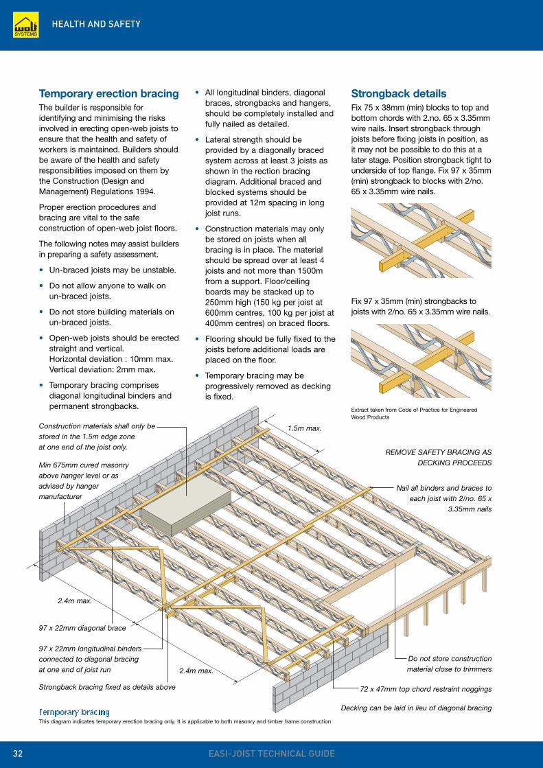
Temporary erection bracingThe builder is responsible foridentifying and minimising the risksinvolved in erecting open-web joists toensure that the health and safety ofworkers is maintained. Builders shouldbe aware of the health and safetyresponsibilities imposed on them bythe Construction (Design andManagement) Regulations 1994.
Proper erection procedures andbracing are vital to the safeconstruction of open-web joist floors.
The following notes may assist buildersin preparing a safety assessment.
• Un-braced joists may be unstable.
• Do not allow anyone to walk onun-braced joists.
• Do not store building materials onun-braced joists.
• Open-web joists should be erectedstraight and vertical.Horizontal deviation : 10mm max.Vertical deviation: 2mm max.
• Temporary bracing comprisesdiagonal longitudinal binders andpermanent strongbacks.
• All longitudinal binders, diagonalbraces, strongbacks and hangers,should be completely installed andfully nailed as detailed.
• Lateral strength should beprovided by a diagonally bracedsystem across at least 3 joists asshown in the rection bracingdiagram. Additional braced andblocked systems should beprovided at 12m spacing in longjoist runs.
• Construction materials may onlybe stored on joists when allbracing is in place. The materialshould be spread over at least 4joists and not more than 1500mfrom a support. Floor/ceilingboards may be stacked up to250mm high (150 kg per joist at600mm centres, 100 kg per joist at400mm centres) on braced floors.
• Flooring should be fully fixed to thejoists before additional loads areplaced on the floor.
• Temporary bracing may beprogressively removed as deckingis fixed.
Extract taken from Code of Practice for EngineeredWood Products
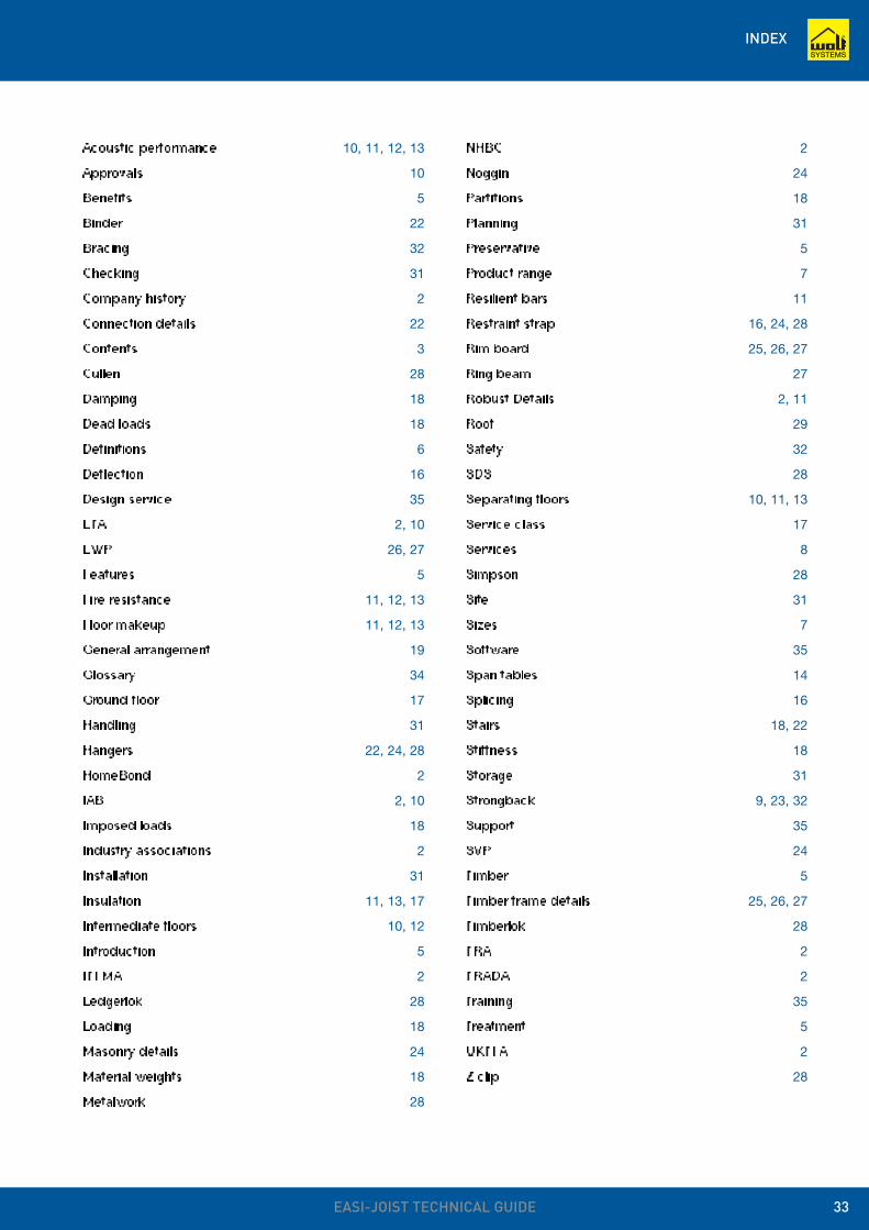
Strongback detailsFix 75 x 38mm (min) blocks to top andbottom chords with 2.no. 65 x 3.35mmwire nails. Insert strongback throughjoists before fixing joists in position, asit may not be possible to do this at alater stage. Position strongback tight tounderside of top flange. Fix 97 x 35mm(min) strongback to blocks with 2/no.65 x 3.35mm wire nails.
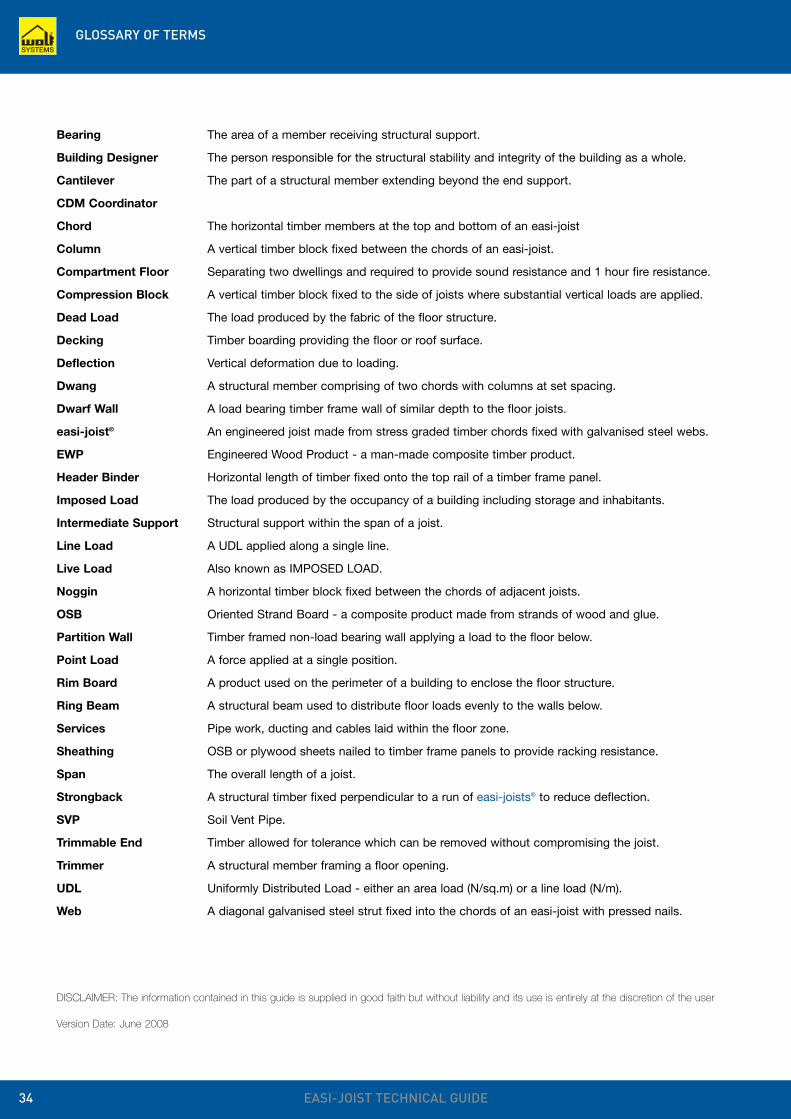
Fix 97 x 35mm (min) strongbacks tojoists with 2/no. 65 x 3.35mm wire nails.
Temporary bracing
Nail all binders and braces toeach joist with 2/no. 65 x
3.35mm nails
Construction materials shall only bestored in the 1.5m edge zone at one end of the joist only.
Do not store constructionmaterial close to trimmers
97 x 22mm diagonal brace
97 x 22mm longitudinal bindersconnected to diagonal bracingat one end of joist run
Strongback bracing fixed as details above 72 x 47mm top chord restraint noggings
Decking can be laid in lieu of diagonal bracing
Min 675mm cured masonryabove hanger level or asadvised by hangermanufacturer
1.5m max.
2.4m max.
2.4m max.
This diagram indicates temporary erection bracing only. It is applicable to both masonry and timber frame construction
REMOVE SAFETY BRACING ASDECKING PROCEEDS
INDEX
EASI-JOIST TECHNICAL GUIDE 33
Acoustic performance 10, 11, 12, 13
Approvals 10
Benefits 5
Binder 22
Bracing 32
Checking 31
Company history 2
Connection details 22
Contents 3
Cullen 28
Damping 18
Dead loads 18
Definitions 6
Deflection 16
Design service 35
ETA 2, 10
EWP 26, 27
Features 5
Fire resistance 11, 12, 13
Floor makeup 11, 12, 13
General arrangement 19
Glossary 34
Ground floor 17
Handling 31
Hangers 22, 24, 28
HomeBond 2
IAB 2, 10
Imposed loads 18
Industry associations 2
Installation 31
Insulation 11, 13, 17
Intermediate floors 10, 12
Introduction 5
ITFMA 2
Ledgerlok 28
Loading 18
Masonry details 24
Material weights 18
Metalwork 28
NHBC 2
Noggin 24
Partitions 18
Planning 31
Preservative 5
Product range 7
Resilient bars 11
Restraint strap 16, 24, 28
Rim board 25, 26, 27
Ring beam 27
Robust Details 2, 11
Roof 29
Safety 32
SDS 28
Separating floors 10, 11, 13
Service class 17
Services 8
Simpson 28
Site 31
Sizes 7
Software 35
Span tables 14
Splicing 16
Stairs 18, 22
Stiffness 18
Storage 31
Strongback 9, 23, 32
Support 35
SVP 24
Timber 5
Timber frame details 25, 26, 27
Timberlok 28
TRA 2
TRADA 2
Training 35
Treatment 5
UKTFA 2
Z clip 28
GLOSSARY OF TERMS
EASI-JOIST TECHNICAL GUIDE34
Bearing The area of a member receiving structural support.
Building Designer The person responsible for the structural stability and integrity of the building as a whole.
Cantilever The part of a structural member extending beyond the end support.
CDM Coordinator
Chord The horizontal timber members at the top and bottom of an easi-joist
Column A vertical timber block fixed between the chords of an easi-joist.
Compartment Floor Separating two dwellings and required to provide sound resistance and 1 hour fire resistance.
Compression Block A vertical timber block fixed to the side of joists where substantial vertical loads are applied.
Dead Load The load produced by the fabric of the floor structure.
Decking Timber boarding providing the floor or roof surface.
Deflection Vertical deformation due to loading.
Dwang A structural member comprising of two chords with columns at set spacing.
Dwarf Wall A load bearing timber frame wall of similar depth to the floor joists.
easi-joist® An engineered joist made from stress graded timber chords fixed with galvanised steel webs.
EWP Engineered Wood Product - a man-made composite timber product.
Header Binder Horizontal length of timber fixed onto the top rail of a timber frame panel.
Imposed Load The load produced by the occupancy of a building including storage and inhabitants.
Intermediate Support Structural support within the span of a joist.
Line Load A UDL applied along a single line.
Live Load Also known as IMPOSED LOAD.
Noggin A horizontal timber block fixed between the chords of adjacent joists.
OSB Oriented Strand Board - a composite product made from strands of wood and glue.
Partition Wall Timber framed non-load bearing wall applying a load to the floor below.
Point Load A force applied at a single position.
Rim Board A product used on the perimeter of a building to enclose the floor structure.
Ring Beam A structural beam used to distribute floor loads evenly to the walls below.
Services Pipe work, ducting and cables laid within the floor zone.
Sheathing OSB or plywood sheets nailed to timber frame panels to provide racking resistance.
Span The overall length of a joist.
Strongback A structural timber fixed perpendicular to a run of easi-joists® to reduce deflection.
SVP Soil Vent Pipe.
Trimmable End Timber allowed for tolerance which can be removed without compromising the joist.
Trimmer A structural member framing a floor opening.
UDL Uniformly Distributed Load - either an area load (N/sq.m) or a line load (N/m).
Web A diagonal galvanised steel strut fixed into the chords of an easi-joist with pressed nails.
DISCLAIMER: The information contained in this guide is supplied in good faith but without liability and its use is entirely at the discretion of the user
Version Date: June 2008
DESIGN AND SERVICES
EASI-JOIST TECHNICAL GUIDE 35
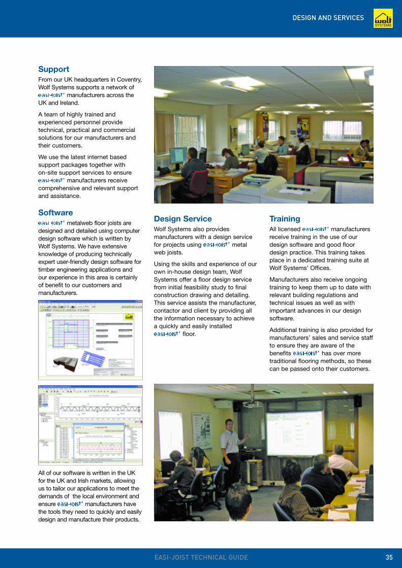
SupportFrom our UK headquarters in Coventry,Wolf Systems supports a network ofeasi-joist® manufacturers across theUK and Ireland.
A team of highly trained andexperienced personnel providetechnical, practical and commercialsolutions for our manufacturers andtheir customers.
We use the latest internet basedsupport packages together with on-site support services to ensure easi-joist® manufacturers receivecomprehensive and relevant supportand assistance.
Softwareeasi-joist® metalweb floor joists aredesigned and detailed using computerdesign software which is written byWolf Systems. We have extensiveknowledge of producing technicallyexpert user-friendly design software fortimber engineering applications andour experience in this area is certainlyof benefit to our customers andmanufacturers.
TrainingAll licensed easi-joist® manufacturersreceive training in the use of ourdesign software and good floordesign practice. This training takesplace in a dedicated training suite atWolf Systems’ Offices.
Manufacturers also receive ongoingtraining to keep them up to date withrelevant building regulations andtechnical issues as well as withimportant advances in our designsoftware.
Additional training is also provided formanufacturers’ sales and service staffto ensure they are aware of thebenefits easi-joist® has over moretraditional flooring methods, so thesecan be passed onto their customers.
Design ServiceWolf Systems also providesmanufacturers with a design servicefor projects using easi-joist® metalweb joists.
Using the skills and experience of ourown in-house design team, WolfSystems offer a floor design servicefrom initial feasibility study to finalconstruction drawing and detailing.This service assists the manufacturer,contactor and client by providing allthe information necessary to achievea quickly and easily installed easi-joist® floor.
All of our software is written in the UKfor the UK and Irish markets, allowingus to tailor our applications to meet thedemands of the local environment andensure easi-joist® manufacturers havethe tools they need to quickly and easilydesign and manufacture their products.