Embed Size (px)
Citation preview

The Cognitive Consequences of
Patterns of Information Flow
Edwin Hutchins
Department of Cognitive Science
University of California, San Diego
Final Report for
NASA Ames Research Center
Cooperative Agreement NCC2-996
0C1 2 S _999
\
1
https://ntrs.nasa.gov/search.jsp?R=19990117006 2018-06-25T00:56:23+00:00Z

Introduction
The flight deck of a modem commercial airliner is a complex system consisting of
two or more' crew and a suite of technological devices. Figure 1 shows the flight
deck of the state-of-the-art Boeing 747-400. When everything goes right, all modem
flight decks are easy to use. When things go sour, however, automated flight decks
provide opportunities for new kinds of problems (Sarter and Woods, 1992). A recent
article in Aviation Week cited industry concern over the problem of verifying the
safety of complex systems on automated, digital aircraft, stating that the industry
must "guard against the kind of incident in which people and the automation seem
to mismanage a minor occurrence or non-routine situation into larger trouble."
(McKenna, 1998). The design of automated flight deck systems that flight crews find
easy to use safely is a challenge in part because this design activity requires a
theoretical perspective which can simultaneously cover the interactions of people
with each other and with technology.
<Figure I about here>
Aeronautical engineers know how to design reliable systems behind the instrument
panel. Behind the mode control panel of Boeing airplanes, for example, there are
multiple pathways for information and redundant processors that do automatic
error checking by comparing signals (see figure 2). In recent years, this sort of
"system thinking' has continued to develop in computer science. An entire field of
computer science called 'distributed AI' studies how intelligent behavior arises in
multi-processor computer systems. One of the challenges facing aviation today is
how to design systems that are reliable on both sides of the instrument panel. Until
very recently, design activities and certification procedures focussed on the
reliability of hardware and software. While studies of human reliability exist, tools
to address the reliability of the system that includes the pilots and technological
devices as system components are lacking.
<Figure 2 about here>
In this paper I will introduce some concepts that can be used to understand the flight
deck as a system that is composed of two or more pilots and a complex suite of
automated devices. As I will try to show, without a theory, we can repeat what
seems to work, but we may not know why it worked or how to make it work in
novel circumstances. Theory allows us to rise above the particulars of specific
situations and makes the application of the roots of success in one setting applicable
to other settings.
To the extent that flight decks have been designed with a theory of cognition even
implicitly in mind, that theory has usually been the standard information processing
theory of cognitive psychology. This view of cognition treats the mind as a logic
' All modem commercial airliner cockpits are designed for two crew members. In
long-haul operations, however, a third crew member is present to relieve the
primary pilots and to provide information support on takeoff and landing.
2

machine, memory as retrieval from a symbolic data base, and problem solving as a
form of logical inference. These central tenets follow from a computational model of
the mind and they have implications for the possible roles of the body and social
world in explanations of cognitive phenomena. Since cognition is taken to happen
in a central processor, "the environment is a problem domain and the body is an
input device" (Clark, 1996). The focus on the individual mind as a computational
device implies that the individual actor should be the principal unit of analysis for
cognition.
DESIGNING FOR THE TOTAL FLIGHTOECK SYSTEM
Following the psychological theory of human information processing, most attempts
to design flight deck systems focus on "the pilot" or on the interaction of "the pilot"
with flight deck controls and instrumentation. Even the very best Human-Centered
design efforts (for example, Charles Billings' recent book on aviation automation
(Billings, 1997) naturally focus on presenting information to "the pilot" rather than
to "the flight crew." It is possible to make quite, a lot of progress with this sort of
theory, but there are many phenomena that are of critical importance to aviation
safety that cannot be addressed in a theoretical framework that explains only the
properties of individual actors.
In recent years, there have been many calls for design decisions that acknowledge
the fact that the crew is a team and that the cognitive system that matters is not the
individual pilot or even the pilots_ Design must consider the entire flight deck
system consisting of two or more people in interaction with each other and now with
a complex suite of automated devices. A recent ALPA report on "Automated
Cockpits and Pilot Expectations" puts the case clearly.
"The performance of the overall flight crew/flight deck system depends on
understanding the total system, its human and automated components and the way
these components interact to accomplish the mission. Each design decision should
consider overall flight safety and efficiency. Combined flight crew/flight deck
system performance is more important than local optimization of the performance of
any human or automated component in that system." (ALPA, 1996:5)
During the same period in which industry attention was shifting from the individual
pilot to the flight deck system, cognitive theory was changing along similar lines.
First, there has been a reconception of the contribution to thinking activity of the
body and of structure in the environment. This is called embodied or ecological
cognition (Clark, 1996; Hutchins, 1995a, Lakoff and Johnson, 1999). Second, it has
become increasingly clear that cognitive processes may be enacted by two or more
persons in interaction with one another. This is the social distribution of cognition
(Hutchins, 1995a). Together they comprise a view called "distributed cognition."
These ideas are not unknown in aeronautics, but neither are they fully integrated
into HCI design philosophies. The recent FAA report titled, "The interfaces between
flightcrews and modem "flight deck systems" (FAA, 1996) has the right wording in
its title, referring as it does to "flightcrews" rather than "the pilot". However, a
careful reading of the report shows that it is still much easier to think about the
3

cognition of individual pilots than to think about the cognitive properties of the full
flight deck system. The question I want to address here is this: How can we actually
design for the interactions among the components of the combined flight crew/flight
deck system?
The goal is to design safe and reliable systems on both sides of the instrument panel
and get both pilots and all the displays and controls in the picture at the same time.
There have already been many successful attempts to design for the total cockpit
system. Crew Resource Management (CRM), the design of altitude change
procedures, and some aspects of lateral navigation displays provide good examples.
Still, many aspects of flight deck operations remain problematic. Autoflight mode
management is a persistent problem. Why do the successful cases succeed and why
do the problems remain unsolved? Until we can answer these questions, we will
have to make do with trial and error methods of design.
SOME SUCCESSES
CRM
Cockpit or Crew Resource Management (CRM) (Wiener, et.al., 1993) provides the
very best example of a fully worked out vision of the system view for one aspect of
the functioning of the flight deck system. It addresses communication among crew
members. But there are other aspects that are less well understood and remain
largely unrecognized. Hints about a wider perspective on the flight deck systems
view come from a variety of sources.
Wiener (1989) conducted observations of crews flying automated airplanes. Among
the many phenomena he noted was the fact that captains complained that they had
difficulty supervising first officers in the use of the flight management computer
system (FMCS) because the control and display unit (CDU) installed at each crew
station is difficult to see from the other crew station. This is a problem brought on by
an interaction between task allocation, display design and the spatial placement ofthe CDU.
<figure 3 about here>
The difficulty described by the captains concerns the movement of information in
the combined flight crew/flight deck system. In particular, the design of the flight
deck deprives the captains of information they would like to have. This design
interferes with a social distribution of cognition. Good CRM provides a partial
solution to this problem by mandating explicit verbal communication of every
change made via the CDU, but one is left to wonder how many of the problems
solved by CRM were created by design decisions that did not give enough
consideration to the patterns of information flow.
Altitude Change Procedure
In the late 1980s, a major airline instituted a procedure to reduce the number of
altitude deviations (Sumwalt, 1991). In this procedure, one pilot sets the target
altitude in the mode control panel (MCP) altitude window, announces the altitude,
4

and points to the altitude window until the other pilot reads the altitude shown inthe window aloud.
<figure 4 about here>
This procedure forces a movement of information so that the altitude is redundantly
represented in the minds of the two pilots. This procedure improves the social
distribution of a cognitive task. Error detection requires a comparison of two or
more representations of the same thing. Every pair of arrowheads arriving at a pilot
in the figure represents an opportunity for error detection. Notice that the modified
procedure creates eight opportunities for error detection and correction whereas the
standard procedure creates only four. This simple procedural change doubles the
number of opportunities for error detection by constructing an appropriate patternof information flow.
Descent to an Altitude Restriction
As a final example, consider the task of making a descent to an altitude restriction at
a waypoint. In order to perform this maneuver it is necessary to determine a descent
rate adequate to satisfy the clearance.
In an older airplane like the DC-10, considerable work is required. Pilots do this by
dividing the distance to the waypoint by present ground speed to get the time to the
waypoint. They then divide the difference in altitude between the current altitude
and the altitude restriction by the time to the waypoint to determine the vertical rate
required.
<figure 5 about here>
If the result is a rate that the pilot knows can be safely achieved, he can then adjust
pitch, thrust, and drag to produce a vertical rate that will satisfy the clearance. Even
allowing for some tricks, such as the fact that Mach number times 10 is
approximately the number of miles the airplane covers in a minute, there is a lot of
cognitive work to do in order to determine the vertical rate required to meet the
restriction. This computation is disembodied decision making. It is done mostly in
the head of the pilot and the displays serve only as sources of input to the
computation.
The navigation displays in the Boeing flight decks offer a feature called the "green
arc." This arc appears on the lateral navigation display (moving map) during
altitude change maneuvers and shows where, in lateral space, the aircraft will reach
the altitude selected in the MCP window based on the present ground speed and the
airplane vertical speed (see figure 6).
To solve the problem in this cockpit, the pilot simply enters the restriction altitude in
the altitude window on the MCP and then manipulates the vertical rate until the
green arc falls between the airplane and the waypoint. This is a computation, but
when a pilot does it using the green arc, it cannot be said that the computation
happens entirely in the aircraft computer (because the computer does not contain a
representation of the clearance linking the altitude to the waypoint), nor is the
computation entirely in the head of a pilot. Rather this computation is performed in
5

the interaction between the pilot, the navigation display, and the way the airplane
responds to pilot inputs of thrust, pitch, and drag. Such a performance defies
traditional function allocation analyses since this function is not allocated to any
single flight deck sub-system. The use of the green arc illustrates the possibility of
embodied decision making. The conceptual question of the altitude of the aircraft at
the waypoint is represented directly and dynamically in the perceptual properties of
the display. With this display it is very easy to monitor progress toward the goal.
Further, since the green arc appears on both navigation displays, it facilitates
montioring by the pilot not flying and supports the formation of shared
understandings about the airplane's situation.
<figure 6 about here>!
Notice that we can apply the same framework to questions concerning pilot
interaction with displays that we applied to pilots interacting with one another. In
both cases, we ask what information is represented, where and how it is represented,
and what patterns of information flow are formed in the activity.
Many design elements that look good in terms of information flow are already
present in the cockpit. But the principles of design for information flow have not
been clearly articulated. Some of what I have said so far seems to be common sense,
but without clear principles it is difficult to fully exploit the potential advantages of
well-designed information flow. This is especially true in aviation, where there are
complex tradeoffs to be made among elements of common sense that are often inconflict with one another.
SOME PERSISTENT PROBLEMS
Autoflight mode management is widely recognized as a continuing problem for
flight crews. I believe that this is not due to poor engineering of system functionality
- the systems are really quite elegant in their operation. Neither is it due entirely to
poor training, although the need for improvement here is widely recognized. The
problem is located in the interface to the autoflight functions. Look at what is
required to make sense of a flight mode annunciation.
<figure 7 about here>
When a pilot selects the VNAV function on the mode control panel, on some models
of airplane, a flowbar in the VNAV mode select switch on the MCP may be
illuminated. This does not mean this mode is engaged, it only means it has been
armed for engagement. To know which mode is engaged, one must look to the FMA.
Here the pilot can read the FMA to see that VNAV SPD is engaged.
But what will this mode attempt to do? There are two issues here. First, what
targets will VNAV SPD attempt to attain? A speed presumably, and possibly
altitudes and other speeds at down-course waypoints as well. To determine what
these targets will be, one must consult two different FMCS pages via the CDU.
Second, how will VNAV SPD attempt to attain those targets? Will it meet the speed
target by controlling thrust or pitch? Here, the interface provides very little help.
The available indications have been likened to a keyhole through which one peeks at
6

the state of the automation. Determining the functional consequences of mode
selection from the character string that names the mode requires complex reasoning.
This task could impose a cognitive workload like that encountered in a non-
automated airplane while computing the rate of descent required to make a crossing
restriction - or perhaps worse if the pilots are unsure how to figure out the
functional consequences of the engaged mode. Consider the three descent modes:
VNAV PTH, V/S, and MCP SPD. If a pilot is instructed to expedite the descent,
what action should he take? Some options are to increase the speed shown in the
MCP speed window, extend the speed brakes, and to click off the autothrottles and
increase thrust. Increasing the speed will increase descent rate in VNAV PTH and
MCP SPD. Extending the speed brakes will increase descent rate only in MCP SPD.
In VNAV PTH it will decrease the descent rate. Adding thrust will increase descent
rate in VNAV PTH mode, but will decrease the descent rate in MCP SPD mode. The
point is that the functional consequences of alternative mode can be quite different•
The air speed tapes in many modern cockpits present a less widely recognized
problem• To see what the problem is, we need to look first at the instruments that
the tapes are intended to replace. Let's take a closer look at the air speed indicator inthe 757.
This traditional instrument has some very nice display properties. It maps the
abstraction of speed onto the physical space of the speed scale. This mapping
permits the pilot to do the conceptual work of reasoning about relationships among
speeds with fast robust perceptual processes. With this instrument it is easy to see,
even in peripheral vision if one is fast or slow. The full operating speed envelope of
the airplane is always visible. The command air speed bug is just 10 knots wide in
the region of the speed scale where approaches are fl0w. This permits a pilot to
know whether the speed in within +/- 5 knots of target with out doing any
computation at all. The designers of the instrument chose this width for the
command airspeed bug so that it would never hide more than one large tic mark at a
time 2. Pilots have discovered that they can put this feature to another use.
<figure 8 about here>
Round-dial air speed indicators are now being replaced by air speed tapes. A lot has
been said over the past 30 years about the advantages and disadvantages of tape
displays. Rather than repeat all that, let me point out that the issues have less to do
with the overall format of the display, tape vs. round dial, than they do with the
ways the properties of the display can be exploited by pilots while doing their jobs.
• <figure 9 about here>
At least one fatal accident has been linked to loss of speed awareness while flying
with a digital airspeed tape. Many pilots complain that they are not comfortable
2 Personal communication with the designer of the 757/767 airspeed indicator
instrument, September, 1991.
7

using the tapes, but they have difficulty explaining why they are not comfortable.
The traditional information processing psychology theory would predict that these
displays should be as useful and usable as the electromagnetic displays they
replaced. The tapes provide the pilots with an accurate and readable representation
of the airplane's airspeed. Common sense tells us that indicating the airspeed must
be the function of the airspeed indicator, but a careful examination of what pilots do
shows that they get more than an indication of current speed from the air speed
indicator. With such a tape display, it is possible to know if one is fast or slow
relative to a target speed, but it isnot so easy to know if one is fast or slow relative to
the current operating envelope of the airplane. And unlike the electromechanical
displays, it is not possible to know much at all about airspeed from the tape without
looking directly at it.
In these brief descriptions I have tried to show how attending to the patterns of
information flow in the flight deck system can help to explain why some
interventions work well and others do not. Let's now look at how the patterns of
information flow produce important cognitive properties of flight deck systems. To
see how these effects are produced, we need a wider view of information flow,
asking what information goes where, when, and under what conditions.
THE COGNITIVE EFFECTS OF PATTERNS OF INFORMATION FLOW
Trajectorles of representations
Open interfaces
The feature of design that most influences what information goes where on the flight
deck is the physical location of displays, controls, and pilots. Physical locationsdetermine how accessible items are to individual actors and the extent to which
interactions with items can be shared by the members of the flight crew. These ideas
have been part of flight deck design for decades. Items that are located in shared
space and that are easily accessible to both crew members so that each can see what
the other may be doing with the item can be said to have an "open interface." They
also support a kind of low-cost monitoring in which each crew member can maintain
awareness of the actions pursued by the other without investing cognitive resources
in seeking out information about the actions of the other.
Consequential Communication
Segal (1995), in a recent paper on design as the choreography of teamwork, provides
one of the few attempts to track unintended as well as intended movements of
information in a cockpit system. He defines a concept of "consequential
communication" as "situations in which engagement in the control task provides
operators with information that is relevant to team coordination." Consequentialcommunication makes verbal communication redundant in a situation where
redundancy is a desirable property.
Auditory Icons
Most cockpit displays are visual displays, so spatial placement for vision is the key
to their accessibility. Auditory displays are accessible in a different way, so
information represented in auditory signals forms different kinds of patterns of
information flow. Modern cockpits are equipped with many auditory alerting
systems. It seems ironic that over the years so many alarms have been added to

cockpits while cockpits have simultaneously been stripped of many useful auditory
cues. In the old 727 cockpit, the sound of the trim wheel spinning was an incidental
cue that a trim adjustment was in progress. In such a cockpit, a trimming action
could become an instance of "consequential communication" because the pilot not
flying could know that the pilot flying was adjusting trim without doing anything in
particular to seek that information. HCI researchers have recently been exploring a
concept they call "auditory icons." Auditory icons are characteristic sounds that
accompany actions. It is possible that we should be adding sounds to the cockpit in
the form of auditory icons. Describing a groupware interface that uses auditory
icons, Gaver and Smith (1990) note,
'_the sounds perform the dual role of providing feedback to an acting user as well as
new information to others. The a_idition of sound seems to add to the feeling of
presence of other uses, and to aid in coordinating activities. Sounds that provide
confirmatory feedback to one user might well be the only indication to another that
certain actions are being performed" (Gaver and Smith, 1990:568). Auditory icons
could be a rich source of information about the status of the airplane and especially
about what the automation or another pilot is doing to control the airplane. Why not
have auditory icons for autoflight mode engagement events?
REDUNDANT PROCESSING
Patterns of information flow that create multiple representations of the same states
of affairs and redundant processing of similar information enhance system
robustness. For example, the procedural practice of having both pilof:s monitor the
active air traffic control (ATC) frequency whenever possible creates a pattern of
redundant processing and a socially distributed memory for clearances. This gives
the flight deck system a property of graceful degradation in the face of local failures.
Such patterns of information flow also support error detection, since error detection
depends on the comparisons among representations of the same thing developed
from different sources or via different processes.
Common ground
In the context of shared knowledge, patterns of information flow that encourage
socially distributed processing of task relevant information lead to the formation of
shared expectations about task performance. Shared expectations are the
foundation of what is known as common-ground or intersubjective understandings.
Intersubjective understanding is a critical component of the establishment of the
meanings of words and actions. It is "through intersubjective understanding that
even the absence of action can become meaningful in interactions among member ofthe crew.
For example, when the pilot responsible for communications with ATC fails to
respond to a clearance, the absence of a response becomes a very meaningful event
for the other crew member. The meaning given to that absence of action depends on
the fact that both crew members know what is expected and each knows that the
other knows what is expected.
The need for a framework that helps us understand cognitive systems larger than an
individual become even more apparent when we consider how cultural factors may
9

affect flight deck performance characteristics. Cultural factors nearly always
manifest themselves in the interactions among individuals, and therefore require a
theory that reaches beyond the cognitive properties of the individual. Problems of
cross-cultural interaction often arise as breakdowns of the "common-ground" due to
the lack of sharing of expectations (Perez-Chavez, 1998). Culture is not just
something that other people have. It is not something that only appears when
people from different backgrounds interact. These circumstances make culture more
visible, but culture is present in every moment of every human activity. An
American crew flying an American made airplane in American airspace is a system
full of cultural issues. Even if there were only one culture on earth, we would still
need a cultural approach. Language is a system of conventional symbolic behaviors.
Even if there were only one language on earth, linguistics would still be needed to
explain the organization of language behavior. Language gives meaning to words.
Similarly, an understanding of culture explains the organization of conventional
non-linguistic behavior. Culture gives meaning to action. Cultural issues are
essential to the design of safe systems, but they are mostly misunderstood and
assumed to be someone else's problem.
CRM and the altitude change procedures produce patterns of information flow
among pilots that create redundant representations and intersubjective sharing. The
green arc on the moving map display illustrates patterns of information flow
between pilots and displays and controls that permit conceptual processes to be
cleanly mapped into perceptual and motor processes. This permits pilots to use fast,
robust perceptual and motor processes to do tasks that would otherwise require
brittle reasoning skills.
The problematic cases, autoflight mode management and the airspeed tape, share
patterns of information flow among pilots that fail to create redundant
representations and intersubjective sharing. They create patterns of information
flow between pilots and displays and controls that fail to provide clean mappings
from conceptual processes to perceptual and motor processes.
These examples highlight the embodied nature of cognition and the social
distribution of cognitive processes_ They also suggest that features of design may affect
patterns of information flow which, in turn, produce cognitive consequences for the flight
deck cognitive system.
Air Speed Indicators
Let's look forward now. How could this framework help us design displays or
procedures for the problematic cases of the airspeed indicators and autoflight mode
management?
Consider the round dial ASI again. The traditional round-dial airspeed indicator
provides an example of a display with some useful perceptual properties. In
particular, by placing speed bugs on the perimeter of the instruments, pilots are able
to imagine conceptually meaningful regions of speed-space. The construction of
these conceptually meaningful regions on the face of the instrument permit
flightcrews to manage the correspondences between airspeed and required wing
10

configuration by using fast and robust perceptual processes rather than slow
conceptual processes (Hutchins, 1995b). As was the case in the use of the green arc,
the required computations are in the interaction of the flightcrew with the
instrument, rather than inside either the device or the person.
As technology changes, there is always a danger of discarding useful properties that
were not recognized in the replaced technology. In their current form, the airspeed
tapes that have replaced round-dial instruments in the state-of-the-art cockpits
defeat some of the perceptual strategies of pilots. The new instruments offer few
perceptually salient cues that pilots can map to their concept of fast/slow in the
performance envelope of the airplane. This requires pilots to read the displayed
speed as a number and to subject the representation of that speed to further
• symbolic processing in order to answer the questions that were answered simply by
lookingat the earlier display.
<figure 10 about here>
Boeing's next-generation (NG) cockpits offer a digital round dial ASI. This display
preserves virtually all of the useful properties of the old electromechanical MASI
and adds in the advantages of digital display (labeled speed bugs for example.)
I predict that pilots will like this instrument, but it doesn't help with the problem of
how to redesign the tape. According to the embodied cognition view, two of the
most important features of the electromechanical ASI are first, that its gross physical
appearance is different when the airplane is going fast than when it is going slow
and second, that the entire operating envelope is always visible. These features
permit pilots to develop economical cognitive strategies for interacting with the
display. The airspeed tape displays destroy these features. The overall appearance
of the display is the same regardless of speed, and usually the limits of the speed
envelope are not displayed. The NG MASI restores these properties by copying the
old device. Now that we have an idea what the critical features are, we could add
them to the tape display.
<figure 11 about here>
The airspeed tape display in the integrated mode management interface always
shows the current operating envelope and permits pilots to know where the current
speed is in that envelope. The relative position of the speed box in the display is
perceptually salient and permits the pilot to judge the relative speed of the airplane
in peripheral vision.
The creation of shared spaces that can be partitioned into conceptually meaningful
regions supports the development of common-ground understandings,
consequential communication, error checking, low cost monitoring, and the
substitution of robust perceptual processes for vulnerable conceptual processes.
THE INTEGRATED MODE MANAGEMENT INTERFACE
We are just beginning to understand what the design criteria could be for a human
centered design philosophy that goes beyond the individual human operator and
11

takes seriously the notion that the crew consists of two or more operators interacting
with a complex information technology. Let me briefly present an example of an
attempt to do such a design.
I have claimed that the perceptual aspects of the display should map cleanly onto
the underlying conceptual distinctions made by pilots in doing their work. In order
to apply this insight to the problem of autoflight mode management, we would need
to know what conceptual features pilots have in mind or should have in mind when
they are thinking about autoflight modes. I have been conducting a study to discover
the mental models used by pilots to understand autoflight modes - espedally
vertical navigation modes. To do this I have had pilots make judgements of the
similarity of triplets of annunciated mode names. These judgements can be used to
reconstruct conceptual distancb among modes and plot the results in a concept space
as shown in the figure below.
With a little imagination, we can see that there are two principal dimensions to this
space. The modes are implicitly categorized in terms of the source of the
performance target (MCP or FMC) and by the type of target (pitch to speed or pitch
to path).
<figure 12 about here>
The integrated mode management interface IMMI is a prototype of a graphical user
interface to the autoflight system of a state-of-the-art cockpit (Hutchins, 1997). The
design of the IMMI is grounded in this study of the conceptual models employed by
pilots when they reason about the behavior of the autoflight system. Each of the
major conceptual distinctions used by pilots in reasoning about the autoflight system
is represented in the IMMI by a perceptually salient feature. For example, The
source of the performance target for an autoflight mode (e.g., MCP or FMCS) is
indicated by the physical location of an icon denoting the mode. Icons that appear
between the tapes depict modes in which targets are set by the FMCS. Icons that
appear outside the tapes refer to modes in which the targets are set by the crew. The
type of performance target (e.g., pitch-to-speed mode versus pitch-to-path mode) is
indicated by the position of the icon near the speed tape or altitude tape respectively.
<figure 13 about here>
Engagement status of the mode (e.g., available-for-arming, armed, engaged) is
indicated by the color of the icon. The IMMI provides the flightcrew with a display
in which it is easy to establish conceptually meaningful regions of space. The
interface as implemented in the Advanced Concepts Flight Simulator at the NASA-
Ames Research Center provides the flightcrew with a shared and accessible
control/display system. The representations required to understand the current
autoflight mode, to make changes to the mode, and to evaluate the consequences of
changes are all located in the same place. This open-interface design promotes
patterns of information flow that support the creation of common ground
understanding.
12

CONCLUSION
I conclude with some guidelines for design expressed in terms of the patterns of
information flow. In general we should design to create redundant processing
across persons, but not within them. This means we should take advantage of
opportunities to create consequential communication. We should design for
simplicity of processing and shortened trajectories of information within persons.
Where possible, we should reduce the number of representations or representational
forms that are required to guide the appropriate behavior. Sometimes the cost of
changing to a different representation is compensated for by the ease of computation
in the new representation. Where possible, the automation should be given the job
of transforming representations into forms that are easy for people to use. In
general, we should not use automation to make decisions for pilots. Rather we
should use automation to present pilots with representations of decision spaces in
which conceptually meaningful distinctions in the decision space are represented by
perceptually meaningful distinctions in the appearance or behavior of the display.
In such systems, pilots can maintain their engagement with the task of flying and
operating the airplane in an embodied rather than disembodied manner. We should
be building environments for action in which pilots get to be smart by doing what is
easy for them to do. In this way we could bring pilots back into the loop and make
them operators in a meaningful world of action rather than supervisory controllers
of a fully automated process.
Our current generation of flight deck systems contain many robust and reliable
subsystems. I hope the framework I have described today can help us identify
patterns in the current operations that work well and suggest ways that future
designs can preserve what is good about the current system and perhaps help us to
make systems that are even better in the future. Engineers wouldn't think of
removing the redundancy of the avionics systems. If we don't understand these
patterns on the crew side of the instrument panel, we are at risk of inadvertently
disrupting beneficial patterns of information flow.
As Woods and Sarter (1998) note, making progress on the human centered design of
interfaces and procedures will require coordination among many players:
manufacturers, airlines, regulatory agencies, etc. Concerted action can only arise
from a shared perception of a problem. That is what I hope to provide here. The
modest contribution I hope for is to create an awareness of the cognitive
consequences for the flight deck system of patterns of information flow.
13

REFERENCES
ALPA (1996) Automated Cockpits and Pilot Expectations: A guide for manufacturers and Operators.
Unpublished report of the Air Line Pilots Association Automation Team. Herndon Va.
Billings, C. (1997). Aviation Automation. Mahwah, N]: Lawrence Erlbaum Assoc.
Clark A. (1996). Being There: Putting brain, body, and world together again. Cambridge, MA: MIT Press.
FAA (1996). The interfaces between flight crews and modern flight deck systems. Federal Aviation
Administration human factors team report. June, 1996.
Gaver, W. and Smith, R. (1990). Auditory icons in large-scale collaborative environments. Human-
Computer Interaction - INTERACT "90, North-Holland: Elsevier Science Publishers.
Hutchins, E. (1995a). Cognition in the Wild. Cambridge, MA: MIT Press.
Hutchins, E. (1995b). How a cockpit remembers its speeds. Cognitive Science, 19:265-288.
Hutchins, E. (1997). The integrated mode management interface. Final report to contract NCC 2-591.
NASA-Ames Research Center, Moffett Field, CA. October, 1997.
Lakoff, G. and Johnson, M. (1999). Philosophy in the Flesh: The embodied mind and its challenge to Western
thought. New York: Basic Books.
McKenna, J. (1998). Industry, FAA struggle to steer agenda. Aviation Week Vol. 148, No.17:61.
P_rez-Ch_vez, A. (1998). The reconstruction of the social and technological context of the American
Airlines 965 accident. Unpublished ms. Wayne State University, Michigan, January 1998.
Sarter, N. and Woods, D. (1992) Pilot interaction with cockpit automation I: Operational experiences
with the flight management system. International Journal of Aviation Psychology, 2:303-321.
Segal, L. (1995). Designing team workstations: The choreography of teamwork. In P. Hancock J.
Flach, J. Card, & K. Vicente (Eds.) Local Applicaticms of the Ecological Approach to Human-Machine
Systems. Hillsdale, NJ: Lawrence Erlbaum Assoc.
Sumwalt, R. L. (1991). Eliminating Pilot-caused altitude deviations: a human factors approach. Sixth
International Symposium on Aviation Psychology, Columbus, Ohio.
Wiener, E. L. (1989). Human factors of advanced technology ("glass-cockpit') transport aircraft.
NASA contractor report No. 177528. Moffett Field, CA: NASA-Ames Research Center.
Wiener, E. L., Kanki, B. G., and Helmreich, R. L. (1993). Cockpit Resource Management. New York:
Academic Press.

Woods, D., & Sarter, N. (1998). Learning from automation surprises and "going sour" accidents:
Progress on Human-Centered automation. Final report to contract NCC 2-592, NASA-Ames Research
Center, Moffett Field, CA. January 19, 1998.

Figure 1. Flight deck of the Boeing 747-400.

G
I I • II I I
I
I I Ir ! !
i , I I
I_,_ _ SU_II
Figure 2. A system diagram describing what lies behind the mode control
panel in a modern airplane.
eeO _]ee O_
•0 Co@ 0 ' !
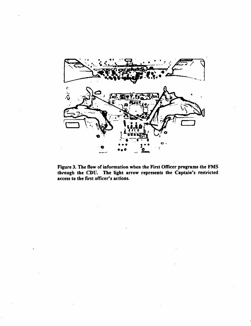
Figure 3. The flow of information when the First Officer programs the FMS
through the CDU. The light arrow represents the Captain's restricted
access to the first officer's actions.

Figure 4. The flow of information in the altitude changeprocedure. Heavy blue
arrows indicate mandatory information exchange, light blue arrows are
discretionary, red arrows represent new mandatory information trajectories
introduced by the modified procedure.

Figure 5. The flow of information in a non-automated cockpitwhen making a descentto crossa waypoint at a specified altitude.

Figure 6. The flow of information in an automated Boeing cockpitwhile making a descentto crossa waypoint at a specifiedaltitude.

o ,!o. _ ,oaO • O •
Q -|"go@ 0
Figure 7. The flow of information required to interpret the consequences of
selecting a high-level autopilot/flight director mode.

Figure 8. Airspeed indicator from the Boeing757/767

Figure 10. The primary flight instruments in the Boeing Next-Generationcockpit. The digital recreation of the electromechanicai mach/airspeedindicator (MASI) is at the upper left.

Figure 11. Airspeed tape from the Integrated ModeManagementInterface.

, 1
Figure 13. The Integrated l_lode Management Interface (IMMI).