Embed Size (px)
Citation preview

All rights reserved. This dissertation may not be reproduced in whole or in part,by photocopying or other means, without the permission of the author.
University of Victoria
We accept this dissertation as conformingto the required standard
A Dissertation Submitted in Partial Fulfillment of theRequirements for the Degree of
by
The Co-Design of Virtual Machines Using Reconfigurable Hardware
DOCTORATE OF PHILOSOPHY
in the Department of Computer Science
Kenneth Blair KentB.Sc. (hons), Memorial University of Newfoundland, 1996
M.Sc., University of Victoria, 1999
Dr. M. Serra, Supervisor (Department of Computer Science)
Dr. M. Cheng, Member (Department of Computer Science)
Dr. N. Horspool, Member (Department of Computer Science)
Dr. K. Li, Outside Member (Department of Electrical and Computer Engineering)
Dr. R. McLeod, External Examiner (University of Manitoba, Department of Electrical and Computer Engineering)
© Kenneth B. Kent, 2003

Supervisor: Dr. M. Serra
ABSTRACT
The prominence of the internet and networked computing has driven research
efforts into providing support for heterogeneous computing platforms. This has been
exemplified by the emergence of virtual machines, such as the Java virtual machine.
Unfortunately, most virtual computing platforms come with a performance penalty. This
dissertation investigates a new approach for providing virtual computing platforms
through the use of reconfigurable computing devices and hardware/software co-design.
Traditionally, when designing a hardware/software solution, instance specific meth-
ods are used to iterate towards a solution that satisfies the requirements. This is not an
ideal approach as the costs involved with integrating hardware and software components
are significant. This technique demotes the interface between the hardware and software,
often resulting in major complications at the integration stage. These problems can be
avoided through adherence to a sound methodology which the co-design process follows.
This dissertation examines the original concept of using hardware/software co-
design and reconfigurable computing as a means of providing virtual machine platforms.
Specifically the contributions include an advancement towards a new general computing
paradigm and architecture; guidelines and several algorithms for applying the general
hardware/software co-design process to the specific virtual machine class of problems;
and an assessment of the potential advantages of using co-design as an implementation
approach for virtual machines. These are applied to the Java virtual machine and simu-
lated for insights into the potential benefits, requirements, and caveats of co-design for
virtual machines.
This research demonstrates that using hardware/software co-design as described
specifically for virtual machines, the solution can offer performance benefits over a soft-
ware-only solution. These performance increases will be shown to be dependent upon
several factors such as the application itself and the underlying architectural features.
This dissertation will promote and give evidence that reconfigurable computing can be
used for more general purpose computing and not just for specific problem instances.

iii
Dr. M. Serra, Supervisor (Department of Computer Science)
Dr. M. Cheng, Member (Department of Computer Science)
Dr. N. Horspool, Member (Department of Computer Science)
Dr. K. Li, Outside Member (Department of Electrical and Computer Engineering)
Dr. R. McLeod, External Examiner (University of Manitoba, Department of Electrical and Computer Engineering)

iv
Table of Contents Chapter 0
Abstract ............................................................................................................................... ii
Table of Contents............................................................................................................... iv
List of Figures .................................................................................................................... ix
List of Tables ................................................................................................................... xiii
Acknowledgments ........................................................................................................... xiv
Chapter 1 Introduction ....................................................................................1
1.1 Research Contributions...........................................................................................5
1.2 Dissertation Overview ............................................................................................7
Chapter 2 Virtual Machines ............................................................................9
2.1 Introduction.............................................................................................................9
2.2 Virtual Machines.....................................................................................................9
2.3 Virtual Machine Implementation Techniques .......................................................112.3.1 Software Interpreter ................................................................................................ 122.3.2 Just-In-Time Technology........................................................................................ 132.3.3 Native Processor ..................................................................................................... 142.3.4 Hybrid Processor .................................................................................................... 15
2.4 Co-Designing Virtual Machines ...........................................................................16
2.5 Benefits of a Co-Designed Virtual Machine.........................................................18
2.6 Java Virtual Machine ............................................................................................212.6.1 Benchmark Tests..................................................................................................... 23
2.7 Summary...............................................................................................................25
Chapter 3 Hardware/Software Co-Design ....................................................26
3.1 Introduction...........................................................................................................26
3.2 Hardware/Software Co-Design.............................................................................26
3.3 Issues Involved with Co-Design ...........................................................................30

v
3.3.1 Modeling................................................................................................................. 303.3.2 Partitioning ............................................................................................................. 313.3.3 Co-Synthesis ........................................................................................................... 323.3.4 Co-Simulation......................................................................................................... 33
3.4 Reconfigurable Computing...................................................................................343.4.1 Types of Reconfigurable Computing...................................................................... 363.4.2 Field Programmable Gate Arrays ........................................................................... 36
3.5 Summary...............................................................................................................38
Chapter 4 Co-Design Partitioning.................................................................39
4.1 Introduction...........................................................................................................39
4.2 The Process of Partitioning...................................................................................394.2.1 Partitioning Approaches ......................................................................................... 404.2.2 Exploitations of Virtual Machine Partitioning........................................................ 414.2.3 Partitioning Heuristics ............................................................................................ 43
4.3 Software Partition .................................................................................................464.3.1 Loading Data from the Constant Pool .................................................................... 464.3.2 Field Accesses of Classes and Objects ................................................................... 474.3.3 Method Invocation.................................................................................................. 474.3.4 Quick Method Invocation ....................................................................................... 474.3.5 Exceptions .............................................................................................................. 484.3.6 Object Creation....................................................................................................... 484.3.7 Array Creation ........................................................................................................ 484.3.8 Storing to a Reference Array .................................................................................. 494.3.9 Type Checking ........................................................................................................ 494.3.10 Monitors ................................................................................................................. 494.3.11 Accessing the Jump Table ...................................................................................... 504.3.12 Wide Indexing ........................................................................................................ 504.3.13 Long Mathematical Operations .............................................................................. 504.3.14 Returning from a Method ....................................................................................... 514.3.15 Operating System Support...................................................................................... 514.3.16 Software and Hardware Coordination .................................................................... 51
4.4 Hardware Partition................................................................................................524.4.1 Compact Partition ................................................................................................... 53
4.4.1.1 Constant Instructions .................................................................................................544.4.1.2 Stack Manipulation....................................................................................................544.4.1.3 Mathematical Opcodes ..............................................................................................544.4.1.4 Shift and Logical Opcodes ........................................................................................544.4.1.5 Loading and Storing ..................................................................................................554.4.1.6 Casting Operators ......................................................................................................554.4.1.7 Comparison and Branching Operators ......................................................................554.4.1.8 Jump and Return ........................................................................................................554.4.1.9 Miscellaneous Instructions ........................................................................................554.4.1.10 Communication Support............................................................................................56
4.4.2 Host (Common Memory) Partition......................................................................... 56

vi
4.4.2.1 Array Accessing ........................................................................................................564.4.2.2 Length of Arrays........................................................................................................57
4.4.3 Full Partition ........................................................................................................... 574.4.3.1 Quick Loading Data from the Constant Pool ............................................................574.4.3.2 Quick Field Accesses in Classes and Objects ...........................................................58
4.5 Partition Coverage ................................................................................................58
4.6 Summary...............................................................................................................60
Chapter 5 Hardware Design..........................................................................61
5.1 Introduction...........................................................................................................61
5.2 Development Environment ...................................................................................615.2.1 Hot-II Development Environment.......................................................................... 63
5.3 Hardware Design ..................................................................................................65
5.4 Java Hardware Design ..........................................................................................665.4.1 Host Controller ....................................................................................................... 675.4.2 Instruction Buffer.................................................................................................... 675.4.3 Execution Engine.................................................................................................... 685.4.4 Data Cache Controller ............................................................................................ 69
5.5 Design Characteristics ..........................................................................................695.5.1 Comparison to picoJava.......................................................................................... 70
5.6 Hardware Simulator Justification .........................................................................71
5.7 Software Simulator ...............................................................................................745.7.1 Simulator Goals ...................................................................................................... 745.7.2 Simulator Design Overview ................................................................................... 755.7.3 Simulator Implementation Details.......................................................................... 77
5.7.3.1 Signal Propagation.....................................................................................................775.7.3.2 PCI Interface Model ..................................................................................................785.7.3.3 Modeling Memory Caches ........................................................................................795.7.3.4 Primitives Enforcement .............................................................................................805.7.3.5 Simulator Initialization ..............................................................................................81
5.7.4 Simulator Validation ............................................................................................... 815.7.5 Execution Time Measurements .............................................................................. 82
5.8 Results...................................................................................................................835.8.1 Linear Execution Tests ........................................................................................... 845.8.2 Stack Testing........................................................................................................... 855.8.3 Instruction Buffer Testing....................................................................................... 865.8.4 Data Cache Testing ................................................................................................. 865.8.5 Remote Memory Testing ........................................................................................ 875.8.6 Results Analysis ..................................................................................................... 88
5.9 Summary...............................................................................................................89
Chapter 6 Software Design ...........................................................................90
vii
6.1 Introduction...........................................................................................................90
6.2 Software Design....................................................................................................906.2.1 Data Objects Communication................................................................................. 926.2.2 Communication Techniques ................................................................................... 94
6.3 Context Switching.................................................................................................956.3.1 Pessimistic Algorithm............................................................................................. 976.3.2 Optimistic Algorithm.............................................................................................. 986.3.3 Pushy Algorithm..................................................................................................... 99
6.4 Performance Analysis .........................................................................................100
6.5 Results.................................................................................................................101
6.6 Summary.............................................................................................................106
Chapter 7 Benchmark Results.....................................................................107
7.1 Introduction.........................................................................................................107
7.2 Co-Designed Benchmark Results .......................................................................107
7.3 FPGA Performance Requirements......................................................................1127.3.1 Speed Requirements ............................................................................................. 1127.3.2 Space Requirements ............................................................................................. 114
7.4 Hardware/Software Memory Requirements .......................................................1157.4.1 Host Memory Accessing Requirements ............................................................... 1157.4.2 Constant Pool Memory ......................................................................................... 117
7.5 Hardware/Software Communication Requirements ...........................................118
7.6 Application Identification ...................................................................................1227.6.1 High-Level Application Characteristics ............................................................... 123
7.7 Summary.............................................................................................................124
Chapter 8 Conclusions ................................................................................127
8.1 Summary.............................................................................................................127
8.2 Contributions ......................................................................................................128
8.3 Future Work ........................................................................................................130
Appendix A Java Virtual Machine Bytecode Statistics ..............................132
Appendix B Hardware/Software Partitioning .............................................141
Appendix C Context Switching Benchmark Results ..................................151
C.1 Compress Benchmark .........................................................................................151

viii
C.2 Db Benchmark ....................................................................................................153
C.3 Mandel Benchmark.............................................................................................154
C.4 Queen Benchmark...............................................................................................155
C.5 Raytrace Benchmark...........................................................................................156
Appendix D Co-Design Benchmark Results ..............................................157
D.1 Compress Benchmark .......................................................................................157D.1.1 Benchmark with Communication Included .......................................................... 157D.1.2 Benchmark with Communication Excluded......................................................... 159
D.2 Db Benchmark ..................................................................................................161D.2.1 Benchmark with Communication Included .......................................................... 161D.2.2 Benchmark with Communication Excluded......................................................... 163
D.3 Mandelbrot Benchmark ....................................................................................165D.3.1 Benchmark with Communication Included .......................................................... 165D.3.2 Benchmark with Communication Excluded......................................................... 167
D.4 Queen Benchmark.............................................................................................169D.4.1 Benchmark with Communication Included .......................................................... 169D.4.2 Benchmark with Communication Excluded......................................................... 171
D.5 Raytrace Benchmark.........................................................................................173D.5.1 Benchmark with Communication Included .......................................................... 173D.5.2 Benchmark with Communication Excluded......................................................... 175
Bibliography ....................................................................................................................177
Partial Copyright License ................................................................................................188

ix
List of Figures Chapter 0
Figure 1.1 New co-designed virtual machine architecture overview. . . . . . . . . . . . . . . . . . 3
Figure 2.1 Software virtual machine execution layers of abstraction. . . . . . . . . . . . . . . . . 10
Figure 2.2 Abstract architecture for co-designed virtual machine. . . . . . . . . . . . . . . . . . . . 17
Figure 3.1 Traditional hardware/software development. . . . . . . . . . . . . . . . . . . . . . . . . . . . . 28
Figure 3.2 A conventional co-design methodology. . . . . . . . . . . . . . . . . . . . . . . . . . . . . . . . . 29
Figure 3.3 A conceptual field programmable gate array (FPGA). . . . . . . . . . . . . . . . . . . . 37
Figure 4.1 Abstract comparison between traditional and overlapping co-design parti-tioning strategies. . . . . . . . . . . . . . . . . . . . . . . . . . . . . . . . . . . . . . . . . . . . . . . . . . . . . . . 42
Figure 4.2 Abstract view of overlapping partitioning extensions. . . . . . . . . . . . . . . . . . . . 52
Figure 4.3 Instruction coverage for various partitioning schemes (based on instruction execution frequency). . . . . . . . . . . . . . . . . . . . . . . . . . . . . . . . . . . . . . . . . . . . . . . . . . . 59
Figure 4.4 Instruction coverage for various partitioning schemes (based on percentage of overall execution time). . . . . . . . . . . . . . . . . . . . . . . . . . . . . . . . . . . . . . . . . . . . . . 60
Figure 5.1 Hot-II development board architecture. . . . . . . . . . . . . . . . . . . . . . . . . . . . . . . . . . 64
Figure 5.2 Java hardware architecture . . . . . . . . . . . . . . . . . . . . . . . . . . . . . . . . . . . . . . . . . . . . . 66
Figure 5.3 Java hardware architecture’s simulated components. . . . . . . . . . . . . . . . . . . . . . 76
Figure 5.4 Hardware simulator main loop of execution. . . . . . . . . . . . . . . . . . . . . . . . . . . . . 77
Figure 5.5 Block diagram of memories available through the Xilinx Foundation Devel-opment Environment. . . . . . . . . . . . . . . . . . . . . . . . . . . . . . . . . . . . . . . . . . . . . . . . . . . 80
Figure 5.6 Performance increase of hardware architecture. . . . . . . . . . . . . . . . . . . . . . . . . . 85
Figure 5.7 Affects of variable sized instruction cache in Bubble sort. . . . . . . . . . . . . . . . 87
Figure 5.8 Performance degradation for reduced data cache size in Bubble sort. . . . . . 88
Figure 6.1 Overview of interface design between hardware and software. . . . . . . . . . . . 91
Figure 6.2 Software partition design of Java co-processor. . . . . . . . . . . . . . . . . . . . . . . . . . . 92
Figure 6.3 Overview of Java interface design between hardware and software. . . . . . . 92
Figure 6.4 Average communication bandwidth used in context switching. . . . . . . . . . . . 95
Figure 6.5 Inefficient optimistic algorithm bytecode. . . . . . . . . . . . . . . . . . . . . . . . . . . . . . . . 99
Figure 6.6 Required time for augmenting bytecode under each partitioning scheme in the benchmarks for block size of 1. . . . . . . . . . . . . . . . . . . . . . . . . . . . . . . . . . . . . 101
Figure 6.7 Mandelbrot benchmark depicting the decline in augmenting time with the decline in block size. . . . . . . . . . . . . . . . . . . . . . . . . . . . . . . . . . . . . . . . . . . . . . . . . . 102
Figure 6.8 Mandelbrot percentage of hardware instructions. . . . . . . . . . . . . . . . . . . . . . . . 103

x
Figure 6.9 Jess percentage of hardware instructions. . . . . . . . . . . . . . . . . . . . . . . . . . . . . . . 104
Figure 6.10 Average percentage of instructions/context switch. . . . . . . . . . . . . . . . . . . . . . 105
Figure 6.11 Average number of instructions/context switch. . . . . . . . . . . . . . . . . . . . . . . . . 105
Figure 7.1 Benchmark results for ideal operating conditions within co-designed virtual machine. . . . . . . . . . . . . . . . . . . . . . . . . . . . . . . . . . . . . . . . . . . . . . . . . . . . . . . . . . . . . . 108
Figure 7.2 Co-designed virtual machine performance, including communication, with a low speed hardware component. . . . . . . . . . . . . . . . . . . . . . . . . . . . . . . . . . . . . . . . 109
Figure 7.3 Host partitioning scheme performance without PCI communication costs and low speed hardware component. . . . . . . . . . . . . . . . . . . . . . . . . . . . . . . . . . . . . . . . 109
Figure 7.4 Compact partitioning scheme performance without PCI communication costs and low speed hardware component. . . . . . . . . . . . . . . . . . . . . . . . . . . . . . . . . . . . 110
Figure 7.5 Co-designed virtual machine timings with no PCI communication costs, under full partitioning and 1:5 clock rate ratio. . . . . . . . . . . . . . . . . . . . . . . . . . 111
Figure 7.6 Mandelbrot application demonstrating effects of different raw computing speeds. . . . . . . . . . . . . . . . . . . . . . . . . . . . . . . . . . . . . . . . . . . . . . . . . . . . . . . . . . . . . . . . 113
Figure 7.7 Threshold values for communication delays of accessing memory from the host system. . . . . . . . . . . . . . . . . . . . . . . . . . . . . . . . . . . . . . . . . . . . . . . . . . . . . . . . . . . 117
Figure 7.8 Critical section of Mandelbrot application. . . . . . . . . . . . . . . . . . . . . . . . . . . . . . 125
Figure 7.9 Critical section of Raytrace application. . . . . . . . . . . . . . . . . . . . . . . . . . . . . . . . 126
Figure C.1 Number of blocks for each algorithm in Compress benchmark. . . . . . . . . . 151
Figure C.2 Percentage of hardware instructions for each algorithm in Compress bench-mark. . . . . . . . . . . . . . . . . . . . . . . . . . . . . . . . . . . . . . . . . . . . . . . . . . . . . . . . . . . . . . . . . 152
Figure C.1 Number of blocks for each algorithm in Db benchmark. . . . . . . . . . . . . . . . . 153
Figure C.2 Percentage of hardware instructions for each algorithm in Db bench- mark. . . . . . . . . . . . . . . . . . . . . . . . . . . . . . . . . . . . . . . . . . . . . . . . . . . . . . . . . . . . . . . . . 153
Figure C.1 Number of blocks for each algorithm in Mandel benchmark. . . . . . . . . . . . . 154
Figure C.2 Percentage of hardware instructions for each algorithm in Mandel bench-mark. . . . . . . . . . . . . . . . . . . . . . . . . . . . . . . . . . . . . . . . . . . . . . . . . . . . . . . . . . . . . . . . . 154
Figure C.1 Number of blocks for each algorithm in Queen benchmark. . . . . . . . . . . . . . 155
Figure C.2 Percentage of hardware instructions for each algorithm in Queen bench-mark. . . . . . . . . . . . . . . . . . . . . . . . . . . . . . . . . . . . . . . . . . . . . . . . . . . . . . . . . . . . . . . . . 155
Figure C.1 Number of blocks for each algorithm in Raytrace benchmark. . . . . . . . . . . . 156
Figure C.2 Percentage of hardware instructions for each algorithm in Raytrace bench-mark. . . . . . . . . . . . . . . . . . . . . . . . . . . . . . . . . . . . . . . . . . . . . . . . . . . . . . . . . . . . . . . . . 156
Figure D.1 Compress benchmark with compact partitioning scheme (including commu-nication). . . . . . . . . . . . . . . . . . . . . . . . . . . . . . . . . . . . . . . . . . . . . . . . . . . . . . . . . . . . . . 157
Figure D.2 Compress benchmark with host partitioning scheme (including communica-tion). . . . . . . . . . . . . . . . . . . . . . . . . . . . . . . . . . . . . . . . . . . . . . . . . . . . . . . . . . . . . . . . . . 158
xi
Figure D.3 Compress benchmark with full partitioning scheme (including communica-tion). . . . . . . . . . . . . . . . . . . . . . . . . . . . . . . . . . . . . . . . . . . . . . . . . . . . . . . . . . . . . . . . . . 158
Figure D.4 Compress benchmark with compact partitioning scheme (excluding commu-nication). . . . . . . . . . . . . . . . . . . . . . . . . . . . . . . . . . . . . . . . . . . . . . . . . . . . . . . . . . . . . . 159
Figure D.5 Compress benchmark with host partitioning scheme (excluding communica-tion). . . . . . . . . . . . . . . . . . . . . . . . . . . . . . . . . . . . . . . . . . . . . . . . . . . . . . . . . . . . . . . . . . 159
Figure D.6 Compress benchmark with full partitioning scheme (excluding communica-tion). . . . . . . . . . . . . . . . . . . . . . . . . . . . . . . . . . . . . . . . . . . . . . . . . . . . . . . . . . . . . . . . . . 160
Figure D.7 Db benchmark with compact partitioning scheme (including communica-tion). . . . . . . . . . . . . . . . . . . . . . . . . . . . . . . . . . . . . . . . . . . . . . . . . . . . . . . . . . . . . . . . . . 161
Figure D.8 Db benchmark with host partitioning scheme (including communica- tion). . . . . . . . . . . . . . . . . . . . . . . . . . . . . . . . . . . . . . . . . . . . . . . . . . . . . . . . . . . . . . . . . . 162
Figure D.9 Db benchmark with full partitioning scheme (including communication). 162
Figure D.10 Db benchmark with compact partitioning scheme (excluding communica-tion). . . . . . . . . . . . . . . . . . . . . . . . . . . . . . . . . . . . . . . . . . . . . . . . . . . . . . . . . . . . . . . . . . 163
Figure D.11 Db benchmark with host partitioning scheme (excluding communica- tion). . . . . . . . . . . . . . . . . . . . . . . . . . . . . . . . . . . . . . . . . . . . . . . . . . . . . . . . . . . . . . . . . . 163
Figure D.12 Db benchmark with full partitioning scheme (excluding communica- tion). . . . . . . . . . . . . . . . . . . . . . . . . . . . . . . . . . . . . . . . . . . . . . . . . . . . . . . . . . . . . . . . . . 164
Figure D.13 Mandelbrot benchmark with compact partitioning scheme (including com-munication). . . . . . . . . . . . . . . . . . . . . . . . . . . . . . . . . . . . . . . . . . . . . . . . . . . . . . . . . . 165
Figure D.14 Mandelbrot benchmark with host partitioning scheme (including communi-cation). . . . . . . . . . . . . . . . . . . . . . . . . . . . . . . . . . . . . . . . . . . . . . . . . . . . . . . . . . . . . . . 166
Figure D.15 Mandelbrot benchmark with full partitioning scheme (including communica-tion). . . . . . . . . . . . . . . . . . . . . . . . . . . . . . . . . . . . . . . . . . . . . . . . . . . . . . . . . . . . . . . . . . 166
Figure D.16 Mandelbrot benchmark with compact partitioning scheme (excluding com-munication). . . . . . . . . . . . . . . . . . . . . . . . . . . . . . . . . . . . . . . . . . . . . . . . . . . . . . . . . . 167
Figure D.17 Mandelbrot benchmark with host partitioning scheme (excluding communi-cation). . . . . . . . . . . . . . . . . . . . . . . . . . . . . . . . . . . . . . . . . . . . . . . . . . . . . . . . . . . . . . . 168
Figure D.18 Mandelbrot benchmark with full partitioning scheme (excluding communi-cation). . . . . . . . . . . . . . . . . . . . . . . . . . . . . . . . . . . . . . . . . . . . . . . . . . . . . . . . . . . . . . . 168
Figure D.19 Queen benchmark with compact partitioning scheme (including communica-tion). . . . . . . . . . . . . . . . . . . . . . . . . . . . . . . . . . . . . . . . . . . . . . . . . . . . . . . . . . . . . . . . . . 169
Figure D.20 Queen benchmark with host partitioning scheme (including communica-tion). . . . . . . . . . . . . . . . . . . . . . . . . . . . . . . . . . . . . . . . . . . . . . . . . . . . . . . . . . . . . . . . . . 170
Figure D.21 Queen benchmark with full partitioning scheme (including communica- tion). . . . . . . . . . . . . . . . . . . . . . . . . . . . . . . . . . . . . . . . . . . . . . . . . . . . . . . . . . . . . . . . . . 170
Figure D.22 Queen benchmark with compact partitioning scheme (excluding communica-tion). . . . . . . . . . . . . . . . . . . . . . . . . . . . . . . . . . . . . . . . . . . . . . . . . . . . . . . . . . . . . . . . . . 171

xii
Figure D.23 Queen benchmark with host partitioning scheme (excluding communica-tion). . . . . . . . . . . . . . . . . . . . . . . . . . . . . . . . . . . . . . . . . . . . . . . . . . . . . . . . . . . . . . . . . . 172
Figure D.24 Queen benchmark with full partitioning scheme (excluding communica-tion). . . . . . . . . . . . . . . . . . . . . . . . . . . . . . . . . . . . . . . . . . . . . . . . . . . . . . . . . . . . . . . . . . 172
Figure D.25 Raytrace benchmark with compact partitioning scheme (including communi-cation). . . . . . . . . . . . . . . . . . . . . . . . . . . . . . . . . . . . . . . . . . . . . . . . . . . . . . . . . . . . . . . 173
Figure D.26 Raytrace benchmark with host partitioning scheme (including communica-tion). . . . . . . . . . . . . . . . . . . . . . . . . . . . . . . . . . . . . . . . . . . . . . . . . . . . . . . . . . . . . . . . . . 174
Figure D.27 Raytrace benchmark with full partitioning scheme (including communica-tion). . . . . . . . . . . . . . . . . . . . . . . . . . . . . . . . . . . . . . . . . . . . . . . . . . . . . . . . . . . . . . . . . . 174
Figure D.28 Raytrace benchmark with compact partitioning scheme (excluding commu-nication). . . . . . . . . . . . . . . . . . . . . . . . . . . . . . . . . . . . . . . . . . . . . . . . . . . . . . . . . . . . . . 175
Figure D.29 Raytrace benchmark with host partitioning scheme (excluding communica-tion). . . . . . . . . . . . . . . . . . . . . . . . . . . . . . . . . . . . . . . . . . . . . . . . . . . . . . . . . . . . . . . . . . 176
Figure D.30 Raytrace benchmark with full partitioning scheme (excluding communica-tion). . . . . . . . . . . . . . . . . . . . . . . . . . . . . . . . . . . . . . . . . . . . . . . . . . . . . . . . . . . . . . . . . . 176
xiii
List of Tables Chapter 0
Table 5.1. Ackerman function timings in clock cycles. ...............................................................85
Table 5.2. Minimal performance increase factors for each of the benchmarks based on cycle counts without consideration for clock rates. ..................................................89
Table 7.1. Threshold FPGA: Host speed ratios. ...........................................................................113
Table 7.2. Constant pool caching efficiency measurements.....................................................118
Table 7.3. Percentage of original execution times with full partitioning scheme and 1:5 FPGA:Host ratio, including communication delays...............................................119
Table 7.4. Average number of hardware cycles/context switch for each benchmark.......121
Table 7.5. Optimal performance increases under ideal conditions.........................................122
Table 7.6. Instruction support and density for various benchmarks. .....................................123
Table A.1. Java bytecode data collection for five benchmark applications..........................139
Table B.1. Specification of Java virtual machine instruction set between partitioning schemes. ...............................................................................................................................150

xivxivxiv
Acknowledgments
Many people contributed to the completion of this work. Special thanks to my
supervisor, Dr. Serra. I am sure I withered away a few years of her lifespan in trying to
complete this degree. To Jon, he enjoyed me as a masters student so much he recom-
mended me to Micaela for the Ph.D. That must say something! I also want to thank Dr.
Li for his help over the last few months to finish the loose ends.
To the VLSI group which suffered through many of my presentations while I
gave various dry-runs for conferences and invited talks. Especially Duncan for the
motivation in who will finish first. To the Graduate Students Society for having the
lounge open every friday, there was no better place for escaping from the research at
the end of the week. To Sean for giving me a personal demonstration of when you
should stop drinking and Barry for showing me when NOT to ride a bike!
Thanks to my good buddy Gord who from rough calculations I have shared 24
kegs of beer and a few bottles of scotch with over 6 years. What else can I say but ...
wow!!! No wonder people go to the bathroom so often when drinking.
Last but not least, to my family. Without their constant mocking about being
under worked and a student for life, I never would have aspired to make the jump to
becoming a glorified permanent student while getting paid ... a university professor :)

xvxvxv
for my family

CHAPTER 1
Introduction Chapter 1
This dissertation examines the merging of three problems that exist in computing
today. The first problem is the slow performance of virtual machines that, with the
increasing importance of the internet, have become popular for providing a homoge-
neous platform. The second problem is moving reconfigurable computing from the appli-
cation specific domain into a new general purpose computing platform. The third
problem is that of instance specific techniques used to develop hardware/software co-
designed solutions to systems, in this case specifically to virtual machines. This is attrib-
uted to the complexity and variety in types of co-designed systems being developed. This
dissertation investigates using reconfigurable computing in a co-designed system to alle-
viate some performance issues of virtual machines.
Homogeneous computing techniques have become increasingly important with the
increase in internet usage and types of services. This usage continues to increase at an
exponential rate [57]. A popular means by which to provide a homogeneous platform is
through the use of a virtual machine. This solution is desirable since it guarantees a com-
mon platform and also allows users to maintain preferential heterogeneous hardware
underneath. The drawback however is the inherent slow performance of adding another
layer of abstraction between the end application and the underlying computing devices.
A tremendous amount of research has been performed into virtual machines and
how to improve their performance [2,3,8,18,19,30,41,75,79,81,94,101,116]. Techniques
have spanned all aspects of the execution paradigm including better source code and
compilation techniques, just-in-time compilation and replacing software with hardware.
Some of these techniques have provided respectable performance increases and are com-
monly used in virtual machine implementations, while others have not reached the main-
stream. While the gap in performance has decreased, there is still a performance loss from
execution on a virtual computing platform.

2
Despite this, virtual machines are used in many contexts and applications ranging
from large scale complete general purpose computing platforms to low-level specific
embedded systems. Within these, a virtual machine’s features and capabilities must be
adjusted to reflect the support provided by and required of the environment. This work
strives towards providing a full implementation of a general purpose abstract virtual
machine within the context of the desktop workstation.
The implementation of the full virtual machine, as opposed to a subset of the vir-
tual machine, is desirable since it allows a demonstration of the effectiveness of using a
reconfigurable computing device in a general purpose computing platform. This raises
issues such as the partitioning of the virtual machine between hardware and software, the
dynamic run-time decisions for where to execute a given code segment, as well as neces-
sary communication requirements. To reduce the problem into examining a subset of a
virtual machine that exists only in hardware would remove this investigation.
There currently exist a variety of approaches to providing a computing platform
such as a virtual machine. Some of these include: a dedicated hardware processor; a co-
processor specific for the platform; and a full software implementation. While each of
these have their merits, they also have disadvantages. The dedicated processor and co-
processor solutions are costly if the fabricated hardware requires replacement to adapt if
the virtual machine specification were to change. This is in addition to the complexities
encountered in either incorporating the virtual machine support in an existing platform, or
adding support for other platforms within the virtual machine itself. The software-only
solution provides desirable flexibility and maintainability, but suffers in performance.
With the development of systems that incorporate both hardware and software com-
ponents, there is a need for methodologies to assist the process. The tradition for hard-
ware components has been that they are expensive and time consuming to develop. As
such, traditional viewpoints have grown to the expectation that software, with its inher-
ent flexibility, will adapt and suit the needs of the hardware resources. With the emer-
gence of flexible reconfigurable hardware, the scope of possibilities is widened
considerably.
Hardware/software co-design is the cooperative design of both hardware and soft-

3
ware for a specific system. Encompassing the full design process, it is concerned with
many aspects such as the partitioning of the system between hardware and software
through to the system integration and testing. To aid in the process, many tools, tech-
niques, and methodologies have been proposed and examined. However due to the wide
range of co-designed systems no single detailed approach or tool solution exists. There is
a general process that co-designed systems follow, but it usually requires a lot of custom-
izing to be applicable in practice to a diversity of systems. This dissertation focuses on
hardware/software co-design for virtual machines, not for all systems.
The co-designed solution here differs in that it provides an implementation that
attempts to incorporate the advantages of the previous methodologies. This is accom-
plished by dividing cleverly the virtual machine specification between a hardware and
software partition. Both of these partitions are then realized in their respective environ-
ments through the utilization of the system processor and a reconfigurable logic device.
This results in a new virtual machine architecture as depicted in Figure 1.1, where each
partition is supported by a different resource. The software and memory are provided
through the general purpose CPU and RAM available on the local host. The hardware,
however, is provided through a reconfigurable computing device.
Reconfigurable computing is an emerging research area which utilizes programma-
Software(host processor)
Hardware(reconfigurable)
Memory
Figure 1.1 New co-designed virtual machine architecture overview.

4
ble hardware devices to provide an inexpensive custom hardware solution to a problem.
Devices exist such that a user can develop a hardware design using software tools and
then program the device to provide the implementation, which becomes the custom hard-
ware. Once the hardware design is completed, the programming of the device requires
only microseconds. Typically the problems addressed to date have been instance specific
and narrowly focused due to the limited capabilities of the programmable devices them-
selves and the environments within which they exist. While the approach presented here
is focused only on virtual machines, it is supportive of multiple applications executing
within the platform. The previous more narrowly focused use has led to the predominant
use of instance specific techniques for design and implementation of the solutions. The
techniques in this dissertation attempt to be more general and can be applied to the co-
design of most virtual machines.
The potential advantages of reconfigurable computing have been great enough to
solicit a high level of interest [12,91]. Reconfigurable devices are being seen as a cheap
alternative for custom hardware. This coupled with reprogrammability allows for quicker
time to market, iterative development, and backwards compatibility. These features sug-
gest that reconfigurable computing will only become even more pervasive in the future.
Reconfigurable computing has been used in many small application specific
instances to increase performance [15,82,84]. The idea of using reconfigurable computing
as an approach to solve the slow performance of virtual machines is new. Virtual
machines are used to satisfy primarily the requirement of having a common platform
across architectures. An immediate solution guaranteeing that a common platform exists
is to simply have everyone use the same underlying hardware architecture. While this
may be an ideal scenario, it is not a cost effective or feasible solution. Using reconfig-
urable technologies to provide a virtual machine is potentially more cost effective than
the traditional Application Specific Integrated Circuit (ASIC) approach for providing a
common underlying hardware architecture. Instead of replacing the underlying hardware
with a new platform, the user simply reconfigures to the desired new platform [45]. While
the success of such an approach to provide virtual machines is unknown, there are obvi-
ous conjectures that are interesting to explore.

5
This dissertation describes a different approach of computing for virtual machines
through hardware/software co-design and the utilization of reconfigurable hardware, by
providing guidelines and several algorithms that focus on important co-design phases of
the process such as partitioning, design of the components with flexibility, and of the
interface linking them together. From this research results are gathered concerning the
required support for success. Included as well are performance measurements that can be
attained through this solution.
1.1 Research Contributions
There are three major research contributions of this dissertation and they include: an
advancement towards a new general computing paradigm and architecture; a set of guide-
lines and algorithms for applying the general hardware/software co-design process to the
specific virtual machine class of problems; and an assessment of the potential advantages
of using co-design as an implementation approach for virtual machines. The remainder of
this section will focus on each of these contributions and discuss them in more detail.
The first contribution is to make advances towards a new view of a general comput-
ing platform and architecture. This approach provides a computing platform which is sup-
ported by both hardware and software components through a static partitioning of instruc-
tions. By overlapping the partitions as well, a decision can be made at run-time as to the
location of execution for a user application. Reconfigurable technologies to date have
been focusing at the application level. This dissertation examines reconfigurable comput-
ing at the operating system and computer architecture level. This allows applications to
be written without knowledge of the specialized hardware, yet receiving the benefits.
The second contribution is to outline a set of guidelines to assist in the transition of
a virtual machine into this new computing paradigm, which must efficiently utilize the
existing general purpose processor and the new reconfigurable resources. A significant
component of this utilization is the dynamic selection of application regions to execute in
the hardware partition. The partitioning scheme used to determine the opcodes that form
the hardware component is critical to the outcome. Any partitioning strategy used must

6
deal with the challenges of resource constraints, such as design space and memory, as
well as implementation costs.
Co-design is new and interesting, but has been used mainly for embedded systems,
where the main implementation implies having closely connected software and hard-
ware portions and a well-defined interface. Here, a general process for co-design has been
established, but the process is generic to suit all systems. This leaves the co-designer with
little direction to address each of the steps within the co-design process. Steps such as
partitioning become more focused only when restricted to a particular and narrow domain
of application. In this research specific techniques are applied within each of the process
steps for virtual machines to obtain better performance and to attempt to provide a more
systematic approach to co-design, when applied to the context of virtual machines.
There are different ways of tackling this idea, for example using a co-processor,
which is very successful in graphics and video streaming. In this case one utilizes a static
partitioning strategy, where the hardware is used to implement specialized instructions or
functionalities. Such solutions are inflexible due to the static partitioning. Likewise, the
implementation using a custom ASIC co-processor also lacks flexibility, and is poten-
tially costly. Instead the use of reconfigurable hardware can provide greater flexibility
and is potentially less costly. This is reflected by the division of the virtual machines
functionalities between hardware and software, the interface between the divisions, and
the dynamic decision process for when to move execution between hardware and soft-
ware during run-time, since the software partition maintains full functionality. Each of
these concerns are addressed and the solutions can be transferred to other virtual comput-
ing paradigms. The general co-design process is described in section 3.2.
Within this approach designed for the class of virtual machines, there are several
issues and ideas that are addressed and they include:
• A partitioning strategy for dividing the virtual machine between hardware
and software.
• The idea of overlapping hardware and software partitions to allow for
selective dynamic context switching. Three algorithms are presented and a

7
demonstration of the importance of context switching execution between
them.
• A generic hardware design that can be adapted and manipulated for other
virtual computing platforms.
• An analysis of the performance of the co-design solution as applied to the
Java virtual machine.
• Lastly, a set of simulated benchmarks that quantifies the performance pre-
diction.
The third contribution is to assess the potential performance increase of virtual
machines that are implemented using hardware/software co-design dependent on the
underlying hardware resources. Specifically, the Java virtual machine is used as an exam-
ple. This includes an examination of the effects the physical resources of the system and
characteristics of the virtual machine’s applications have on the overall performance. A
requirements analysis is also performed on the hardware support needed to provide a suit-
able environment for a co-designed virtual machine to exist. This analysis will include
such factors as memory, communication, and FPGA requirements suitable for this
approach to succeed.
1.2 Dissertation Overview
This dissertation follows through the use of hardware/software co-design for virtual
machines. A detailed discussion of the motivation for co-design and the advantages and
disadvantages of this approach in comparison to other popular methods of implementa-
tion for virtual machines is in chapter two. Chapter three is a background of hardware/
software co-design related information as well as reconfigurable computing and program-
mable hardware devices.
With the foundation set, the proposed application of hardware/software co-design to
virtual machines is described in chapter four, covering the partitioning of the virtual
machine between the hardware and software components. The next two chapters, five and
six, discuss the hardware and software designs of the virtual machine respectively. These

8
designs encapsulate the interface between the partitions. Each of these chapters discusses
co-design as it applies to virtual machines in general, and to the example case study of
Java in particular.
Finally, chapter seven of the dissertation discusses some of the results realized
through the co-design solution. This includes an analysis of some of the results obtainable
through co-design as well as the requirements of the development environment. Chapter
eight concludes the dissertation with a summary and a brief description of some future
work that can evolve.
9
CHAPTER 2
Virtual Machines Chapter 2
2.1 Introduction
This chapter discusses the motivation and new concept for co-designing virtual
machines clarifying the idea and context. The concept of a virtual machine, along with
the advantages and disadvantages of this computing platform approach, is presented. Sev-
eral common techniques for implementing virtual machines within a general purpose
workstation are presented along with their advantages and disadvantages. The co-design
solution proposed in this dissertation is compared and finally the chapter concludes with a
discussion of the Java virtual machine (the example virtual machine that is used through-
out the dissertation), and its suitability in portraying the approach.
2.2 Virtual Machines
There have been many virtual machines used to support and promote different plat-
forms of execution. The term was first introduced in 1959 to describe IBM’s new VM
operating system [76]. In the 1970s, a virtual machine was implemented for SmallTalk
which supported a very high level object-oriented abstraction of the underlying computer
[76]. A virtual machine is defined to be a self-contained operating environment that
behaves as if it is a separate computer [52]. In more concrete terms, the virtual machine is
a software implementation that lies between the application and the operating system. As
such, it is an application that executes other applications. Figure 2.1 shows both an appli-
cation running directly on top of the operating system (on the left), and an application
running on top of a virtual machine.
An advantage of virtual machines over a traditional hardware architecture with an
operating system is system independence. The virtual machine provides a consistent
interface for application programs despite the potentially wide range of underlying hard-

10
ware architectures and operating systems. This allows the application developers to pro-
vide only one software binary implementation. The key benefits include:
1. Drastically reduces the costs of providing multiple versions of software
across varying platforms.
2. Supports better application development through application portability, a
uniform computing model, and a higher level of programming abstraction.
3. Provides a homogeneous execution platform for distributed computing on
a heterogeneous network.
4. Resolves issues of differing libraries and interfaces between target environ-
ments.
5. Provides the ability for a common security model.
There are other minor advantages such as the low cost of not having specialized
hardware. For these reasons, virtual machines are a good choice to provide a homoge-
neous computing platform.
However, there is a downside to providing an execution environment as a virtual
machine. Because programs running in a virtual machine are abstracted from the specific
system, they often cannot take advantage of any special system features. A key example
of this is the graphics capabilities where specialized acceleration for graphics at the hard-
ware level is common due to the high demands placed on performance by games and
Operating System
Virtual Machine
Application
Figure 2.1 Software virtual machine execution layers of abstraction.
Native Hardware
Operating System
Application
Native Hardware
11
other applications. It is common today for hardware architectures to provide custom
graphics support, for example the Intel processor offers MMX technology and AMD pro-
vides a 3DNow instruction extension [55,1]. While both of these strive to meet the same
goal, their approaches are somewhat different, and so are their interfaces to this special-
ized support. With applications executing within a contained virtual machine that is plat-
form independent, the applications are prevented from accessing this support directly.
This separation of the application from the underlying system is responsible for the
critical drawback of a virtual machine: its performance. Applications that execute on a
virtual machine are not as fast as fully compiled applications that execute directly. The
reason for this is the extra layer of abstraction between the application and the underly-
ing hardware. Any action that is requested by an application before being executed is
interpreted by the virtual machine. In addition, the virtual machine itself requires execu-
tion time to perform maintenance duties such as memory management and security
checking. All of these factors contribute to the overall slow performance of applications
within virtual environments.
With the increasing demand for a homogeneous computing environment, generated
by the internet, and the increasing performance of computers, the use of virtual machines
for computing platforms is more prominent despite some poor performance. New virtual
computing platforms such as the Java virtual machine and the .NET common language
runtime promote this network computing model [17].
2.3 Virtual Machine Implementation Techniques
There are many different approaches to implement a virtual machine. Some of the
more traditional approaches are through either a software interpreter, just-in-time compi-
lation, a dedicated native processor, or using a custom hybrid processor that was opti-
mized to support the virtual platform [43,117]. There are also other less conventional
techniques, mostly targeted for a specific application within the virtual machine and not
the virtual machine itself [18]. Each of these methodologies for implementation has
advantages and disadvantages. The following sub-sections outline the benefits and pitfalls

12
of each of these different approaches. This is followed by a description of the benefits of
co-design, which presents the co-design solution to be an alternative for the desktop
workstation environment.
2.3.1 Software Interpreter
A software interpreter is the most common form of implementation for a virtual
machine. A driving force behind this is that software meets the common demands and
features desired of a virtual machine. Typically virtual machines are “virtual” because
users desire to have portability across different hardware platforms, want a cheap plat-
form, and require backward compatibility as the platform grows into a more stable envi-
ronment. A software computing platform has traditionally been the most appropriate
means by which the implementation can be realized to satisfy these requirements.
The software implementation is the cheapest and quickest means by which the vir-
tual machine can evolve from concept, through prototyping and research, into an end
product. The currently popular Java virtual machine is an example of this evolution. It
originally began as a platform for cable TV switchboxes and continually developed and
grew into the general purpose computing platform that it is today [24]. Currently the Java
platform, since first released as a general purpose computing platform in 1995 has under-
gone four major revisions and numerous other minor editions [103]. Software provides
suitable features for this evolution mainly through its vast set of cheap development tools
and flexibility with underlying hardware architectural platforms. The flexibility that soft-
ware provides for analyzing the virtual machine in terms of configurability provides
insights to help develop efficient and suitable implementation ideas. This flexibility is
also invaluable when the virtual machine has not matured and is changing through contin-
uous revisions. Having the ability to easily update and release a new version is important
during this stage of the virtual machine’s life cycle.
Unfortunately, this is the point where software-based implementation becomes a
burden on the end virtual machine. A software interpreter is a great mechanism for devel-
oping and analyzing the virtual machine, however, its lack of performance hinders the
virtual machine from being used for computing intensive applications. The extra layer of
interpretation in execution is too costly in performance. As can be seen from Figure 2.1,

13
with a software implementation of the virtual machine, there is the extra layer of abstrac-
tion above the host operating system. This extra layer, while providing a standard inter-
face to the underlying hardware, also forbids access to any special capabilities of the
operating system or hardware architecture. In a typical application developed for the
hardware platform, the virtual machine layer does not exist. Instead, the application has
more direct access to the hardware and its special capabilities. There are also advantages
of this abstraction level, as it also acts as a “sandbox”, protecting from illegal access to
other applications and preventing the host operating system from crashing as a result of
the virtual machine application [72].
For performance, this raises even greater concerns when the operating system is
capable of multi-tasking, as it can also result in worse performance as the operating sys-
tem is sharing the hardware resources with other applications, possibly equal in priority to
the virtual machine itself.
2.3.2 Just-In-Time Technology
A common technique that has been used to increase the performance of software
implementations for virtual machines is that of just-in-time (JIT), or hot-spot, compilers.
This technique utilizes the fact that a significant amount of the time during execution is
spent executing a small fragment of the overall application. This technology attempts to
identify these fragments of the application during runtime and compile them into native
code, thus allowing the application to perform faster since it can avoid software interpret-
ing and execute natively [94,103]. Given the correct code fragments of the application to
JIT, the application can almost become a native application. This technique has shown
high levels of performance increase for many virtual computing platforms [103,94].
There are several challenges that just-in-time technologies face. Two factors are
identification of the time critical regions of the application and compilation of the virtual
platform code to execute in the native architecture. Identifying the time critical sections
of an application is difficult since it is dependent on the specific application and requires
monitoring the application during execution. Some of the original Just-in-Time compil-
ers used for Java attempted to compile all of an application methods during loading, but
this resulted in large memory requirements and in compilation of code that is sometimes

14
only used once [119]. Moreover, depending on the input to a given application, the time
critical sections can change. Finally, once identified, compiling the time critical sections
of the application into native code is often a challenging task. This is especially true when
the virtual and native machines differ significantly in architectures. Manipulating the
application to represent it in the supported native instruction set can present a problem
[94]. All of this effort must be performed quickly, as time spent performing the just-in-
time compilation weighs against the performance gains obtained.
2.3.3 Native Processor
When a virtual machine is in high use and performance is of primary importance, it
is common for the platform to become native. For this, a custom processor is developed
based on the instruction set of the virtual platform. This contributes towards providing
higher performance capabilities for the platform’s applications. A key trade-off for this
performance is the loss of flexibility as well as performance for other computing lan-
guages and paradigms [20]. With a native processor, there is less flexibility in evolving
and revising the platform while keeping the proper backwards compatibility. Customiz-
ing the architecture for a specific computing platform or language also causes problems
for executing other platforms and languages. An example of this is the recent picoJava
processor [19,27]. While the specific processor does provide performance gains over soft-
ware emulation, the performance of other computing platforms, such as the execution of
C programs, suffers because the Java specific platform does not offer suitable features as
would another general purpose processor [20].
Another concern that arises from having a native processor for the virtual machine
platform is the support of other platforms. One reason for having various platforms is
because each platform offers different features and capabilities. Using a native processor
may include the features that are desirable for one platform while losing the necessary
characteristics for another. Changing the native processor may be suitable for a dedicated
environment, but not for a general purpose environment where the native processor must
meet a common ground between all supported platforms. In the context of this research,
namely a desktop workstation, the use of a native processor for the targeted virtual
machine is not considered desirable.

15
There are many examples of virtual platforms becoming actual hardware platforms,
such as the Lisp machine, the Pascal processor, and other computer architectures for such
languages as Algol and Smalltalk [39,105,92,22,90,51,77]. Each of these language spe-
cific platforms is capable of providing performance increases simply because the archi-
tecture is targeted to the language and its computing paradigm. For example, the Lisp
machine utilizes the fact that the language is stack based, and hence so too is the architec-
ture. This is also true for more current and emerging computing platforms such as Java
[2,95,99,58,65,117]. These specific examples, despite their demonstration of a perfor-
mance increase over software implementations, have not been adopted as common place
solutions. One contribution to this outcome is the high costs associated with specialized
hardware. In most cases, there is not a sufficient demand for performance on these plat-
forms to warrant the costs.
2.3.4 Hybrid Processor
A hybrid processor attempts to provide greater performance for multiple platforms
by providing a native processor that is based on the combination of the platforms merged
together. This approach in theory provides the best of all the incorporated platforms to
accelerate execution for each virtual machine [29,33]. There has been considerable
research into hybrid processors to specifically enhance the support of Java execution
[3,4,8-10,30-32,79,80]. There are, however, some drawbacks with this approach. Incorpo-
rating multiple virtual machines can result in a very complex design that may be very
challenging to implement. Such factors as design space and cost also arise, sometimes
making this approach impractical.
Having each platform directly supported in the underlying native processor may
lead to increased performance. Again, several drawbacks may mitigate against perfor-
mance gains. There exist many different platforms with many different philosophies that
are not always compatible. Trying to incorporate platforms with a mix of philosophies
can result in a system where each platform is hindered by the other(s). With the vast num-
ber of platform architectures, it is probable that the platforms will have conflicting fea-
tures. Having the scenario of compromising the performance of one platform to improve
another is never desirable and often intolerable.

16
2.4 Co-Designing Virtual Machines
The previous section described several methodologies commonly used to imple-
ment a virtual machine: pure software based, and pure hardware based, with both native
and hybrid instruction sets. Each of these methodologies has its benefits and its costs.
This section instead discusses the idea of co-designed virtual machines using a reconfig-
urable device.
Virtual machines are typically software implementations of a hardware architec-
ture plus supporting software management or operating system. Backward compatibility,
cost, and portability issues are common reasons for providing a platform as a virtual
machine. By having the specified machine in software it can be cheaply implemented and
run on top of, without affecting, many existing host platforms. The motivation behind co-
designing a virtual machine is to increase the performance of the virtual machine’s execu-
tion through hardware support. In this dissertation, the hardware support is provided
through the use of a reconfigurable hardware device, namely a Field Programmable Gate
Array (FPGA).
There are two parts that make up a virtual machine: a low-level instruction set, and
a high level operating system. The idea of co-designing virtual machines is based on sup-
porting each part of the virtual machine by the most desirable approach. Thus, providing
the low-level instruction set of the virtual machine in hardware, i.e. the FPGA, and the
high level operating system in software, i.e. the host processor, is desirable. For the co-
designed solution, an abstract depiction of the conceptual architecture for implementa-
tion is depicted in Figure 2.2.
This architecture is seen as desirable as each part is delivered through technologies
that provide a high level of performance while still maintaining flexibility. The co-design
approach, though simple in concept, faces the new challenge of integrating the hardware
and software components. This requires the careful design of the interface between them.
Architecturally, both of these computing elements are connected via buses to the memory
unit, and to each other. Ideally, there are three separate buses, but sharing a common bus
is possible. This allows for close shared execution between the two devices on one execu-
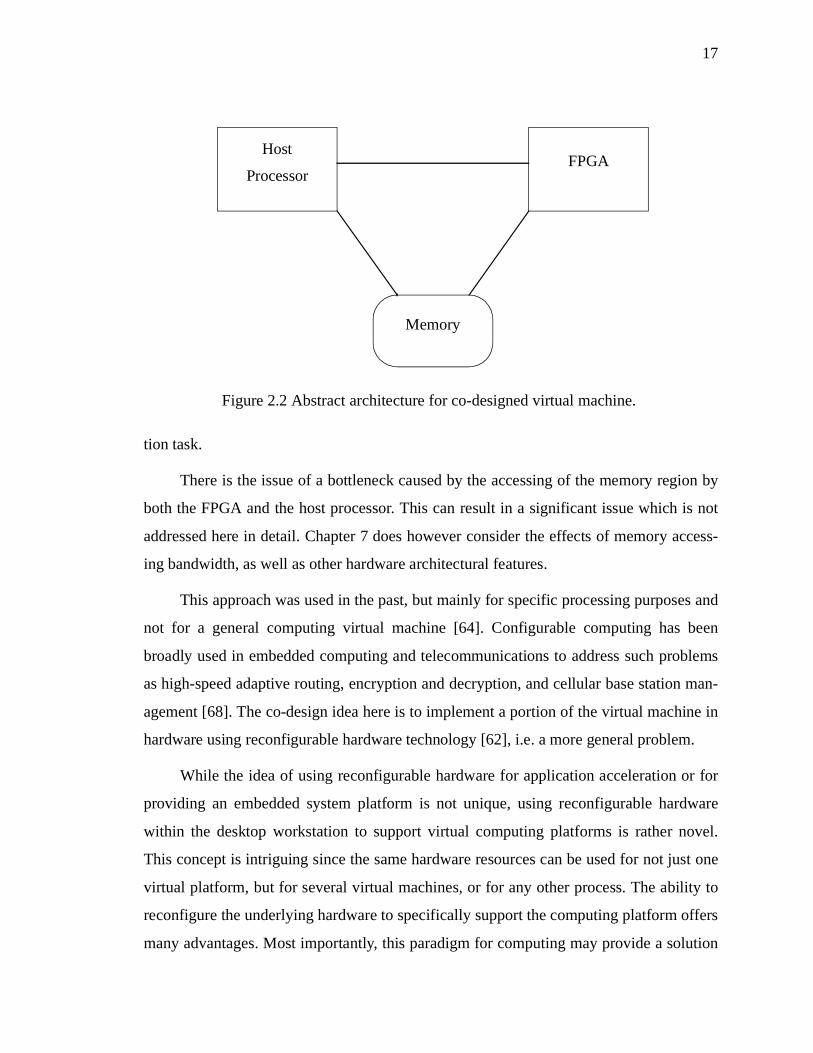
17
tion task.
There is the issue of a bottleneck caused by the accessing of the memory region by
both the FPGA and the host processor. This can result in a significant issue which is not
addressed here in detail. Chapter 7 does however consider the effects of memory access-
ing bandwidth, as well as other hardware architectural features.
This approach was used in the past, but mainly for specific processing purposes and
not for a general computing virtual machine [64]. Configurable computing has been
broadly used in embedded computing and telecommunications to address such problems
as high-speed adaptive routing, encryption and decryption, and cellular base station man-
agement [68]. The co-design idea here is to implement a portion of the virtual machine in
hardware using reconfigurable hardware technology [62], i.e. a more general problem.
While the idea of using reconfigurable hardware for application acceleration or for
providing an embedded system platform is not unique, using reconfigurable hardware
within the desktop workstation to support virtual computing platforms is rather novel.
This concept is intriguing since the same hardware resources can be used for not just one
virtual platform, but for several virtual machines, or for any other process. The ability to
reconfigure the underlying hardware to specifically support the computing platform offers
many advantages. Most importantly, this paradigm for computing may provide a solution
FPGAHost
Processor
Memory
Figure 2.2 Abstract architecture for co-designed virtual machine.

18
to the performance problem of software based implementation virtual machines.
For this to be viable, a co-design flow needs to be developed to assist the implemen-
tation. There exists a general co-design process, but it is too general for virtual machines.
There is little direction provided to assist in how to partition the virtual machine, how to
design the hardware and software components, or what comprises the interface between
them. While assistance for these stages may not be possible for all co-designed systems in
general, it may be possible for virtual machines as a class of problems. Currently, there
exists no assistance for this class of problems beyond the support available for co-
designed systems in general, or for embedded systems more narrowly focused in a
domain. This dissertation will address this problem, by presenting techniques and guide-
lines that can be used specifically for directing the co-design of virtual machines. The
next section discusses in depth the foreseen benefits of a co-designed virtual machine.
2.5 Benefits of a Co-Designed Virtual Machine
A major benefit of any implementation approach for virtual machines is the ability
to change and extend the implementation for revisions to the virtual machine’s specifica-
tion. The use of a co-designed virtual machine promotes this flexibility through the recon-
figurability of the hardware architecture. Revising the implementation is arguably no
more difficult than that of changing a full software implementation. This is not the case
however, when a dedicated ASIC co-processor or hybrid processor is used. In these
instances, changing the hardware can be a high cost venture. The recent Java virtual
machine is an example of this. From a software implementation of the virtual machine,
the Java platform has undergone four major and several minor implementation revisions,
the specification of the virtual machine itself has been revised once, and the Java proces-
sor, picoJava, has undergone a major revision as well [103,72,109,99]. This demonstrates
the importance of having a flexible implementation that can be easily changed to accom-
modate revisions in the virtual machine.
When using a hardware device to provide a service there is always a concern
regarding availability. Even if a hardware device exists to provide the service desired, is

19
the device suitable for the user? Assuming a custom ASIC co-processor were available,
one needs a different type for each different type of virtual machine. It could be envi-
sioned that the host system would contain a general purpose processor along with several
dedicated co-processors on the system mainboard. Is the computing platform for each of
these dedicated co-processors used often enough to justify having dedicated hardware
resources? This is especially true if the performance demand for a particular virtual
machine is low, thus causing a high cost for hardware support. For a dedicated ASIC co-
processor or hybrid processor solution this can be an issue. Using reconfigurable hard-
ware, the same hardware can be used to support multiple computing platforms, thus
amortizing the cost of having this hardware. The cost associated with having a reconfig-
urable device is much less dramatic when several computing platforms can be supported.
It can be envisioned that as each virtual machine is requested by an application, the sys-
tem will reconfigure the hardware to the appropriate virtual machine and then execute.
Thus, only one general processor and one reconfigurable device can theoretically support
an unlimited number of virtual machine types. Moreover such reconfigurable coproces-
sor can support any number of other configurations for any other application.
Cost is always an issue raised when discussing the value of various means of imple-
mentation. This is a rather subjective area to argue when discussing the effort involved to
fulfill the implementation. Past research experience shows that a software implementation
is easier than a hardware implementation because of its flexibility, so a software and JIT
solution would potentially be easier to complete than a co-designed solution. The co-
designed solution, however, is arguably easier to implement than the hybrid solution
which requires integration with a secondary computing platform, and the dedicated co-
processor which involves fabricating the solution.
Often, a computing platform is supported through a virtual machine because it has
an embedded architecture that differs from the native architecture. To attempt to merge
the two computing platforms together to support both paradigms is a very challenging
and often counterproductive process. Some platforms simply cannot be easily merged
based on their underlying fundamental architectures. The co-designed solution avoids this
by having the embedded architecture of the virtual machine supported within its own

20
computing element. This allows the hardware support for the virtual machine to be opti-
mized for its platform, without compromising support for another. This is an advantage
that the co-designed solution provides over the hybrid processor.
The just-in-time compiler solution in some sense performs the complement of the
co-designed approach. The JIT technology transforms the application from the virtual
machine instruction set to the native instruction set of the host processor. Conversely, the
co-designed approach changes the native instruction set to make the application native. In
this sense the co-designed virtual machine has the advantage that the transformation takes
place at compile-time when the reconfigurable device is programmed, while the JIT
transformation takes place at run-time after the time critical section is identified.
When providing a virtual machine through a software emulation environment, the
time critical section of the virtual machine is optimized to take advantage of the underly-
ing hardware architecture to improve performance. When examining the software imple-
mentation of the Java virtual machine, it can be seen that the time critical loop of fetching
and executing instructions is optimized specifically for each hardware platform [103]. It
has both Sparc and Intel architecture modules for that specific component of the virtual
machine. This adds complexity when providing the virtual machine through a new plat-
form as this module is customized for the new underlying hardware architecture. Often
the hardware component of the co-designed virtual machine, which is provided through
reconfigurable logic, overlaps the platform specific components of the software only
solution. In this case, a significant portion of the platform dependencies are removed.
With less need to port platform dependent implementation components of the virtual
machine between platforms, the porting process becomes much simpler. Thus, when a
virtual machine is co-designed for one general desktop platform it can more easily be
manipulated for all desktop platforms.
In some aspects, the co-processor solution and the co-designed approach are very
similar. Both provide additional hardware resources that target specific needs of a com-
puting platform to improve the performance. There are however, three main differences
that separate these approaches. First, the co-designed solution discussed here utilizes
reconfigurable technology. This reduces the cost of hardware resources and allows sup-

21
port for multiple virtual machines as discussed previously. Secondly, the co-processor is
designed to work as an add-on to the general purpose processor. Control flow is dictated
by the CPU and the co-processor just performs fine grained tasks that are requested of it.
The co-designed approach views the added hardware support as an equal processing unit
and as such it contributes to the control flow of an applications execution. This does how-
ever add complexity to the design that may be unnecessary. Thirdly, the co-designed solu-
tion goes beyond simply providing additional hardware support, but addresses the
synergy between the added hardware support and the whole virtual machine. This is seen
later in the dissertation in the discussion of what support to provide in hardware/soft-
ware, where to execute a block of instructions, and how to design the software to work
seamlessly with the hardware support. In a typical co-processor, these issues are not
addressed and instead the design focuses on providing just a standard interface to the co-
processor.
Finally, a major benefit of the co-designed solution is the use of two computing
devices. With the addition of a hardware device, it is now possible to execute two flows
of execution simultaneously. In the simplest of circumstances, this can execute a virtual
machine application and arbitrarily any other application in parallel. If however the vir-
tual machine being used supports multi-threading, this can result in two threads within
the virtual machine executing in parallel. This can result in a further performance gain,
but is not addressed in this dissertation.
2.6 Java Virtual Machine
For this research on co-designing virtual machines, it is as important to show the
application of the approach to a case study virtual machine as it is to describe the
approach itself. While all of the ideas are applicable to virtual machines in general, the
use of a concrete virtual machine allows for some insight into the potential performance
that can be gained through co-design. The use of a case study is also beneficial in exam-
ining some of the more detailed aspects of the co-design approach and from that abstract-
ing the results to form some additional general guidelines to follow in the process. For
this, a case study virtual machine must be chosen and it was decided to use the Java vir-

22
tual machine. That is, the Java virtual machine as within the desktop environment and not
that of a Java platform for use in embedded computing [104,60,69]. While both targets
share some similar problems, they both contain issues that are unique to their usage
[74,78,83].
The Java programming language is a general-purpose object-oriented language
[5,40]. The Java platform was initially developed to address the problems of building
software for networked devices. To provide this support for different types of devices, it
was decided to provide the Java language on top of a virtual machine [71]. The Java vir-
tual machine is the cornerstone of the Java platform. It is the virtual machine that allows
the Java platform to be both hardware architecture and operating system independent.
A key reason for the choice of the Java virtual machine as a case study is its popu-
larity [6]. While it is not crucial that the example virtual machine be popular, it does pro-
vide certain characteristics that are desirable. The amount of Java code that exists from
application developers makes finding and selecting test benchmarks easier. The popular-
ity has also forced Java to mature and become a stable computing environment. The Java
virtual machine is relatively stable and the source code for the software implementation is
freely available for research use. This can be used to avoid implementing supporting
characteristics of the virtual machine that are not important to the research and the co-
design solution, but still allow for a complete virtual machine to be explored. The Java
virtual machine also has a well-defined and freely available specification document of the
virtual machine, as well as substantial reference and specification documents of the Java
based picoJava processor [72,101]. All of this documentation can contribute to making
the co-design process more complete and the implementation more straightforward.
The Java virtual machine is also a good example because of its history. The Java
virtual machine was originally designed very cleanly and precisely. It was internally
developed at Sun Microsystems and encountered many revisions internally before its ini-
tial release as a general purpose computing platform [24]. Supporting the argument is the
fact that original Java programs written when the platform was initially released will still
execute on the latest virtual machine. Since the inception of Java, the platform has been
provided through the virtual machine and there have been several books written concern-

23
ing its specifications. While the Java platform has encountered revisions, the actual Java
virtual machine engine has not evolved very much since its original design and specifica-
tion. Only one specification revision has been made, which avoids the issue of virtual
machine versioning and legacy issues that become part of the virtual machine specifica-
tion.
Finally, the extent to which the Java virtual machine has been researched makes it
an interesting example. Many different methodologies have been used on the Java virtual
machine to increase its performance [21]. Since its introduction, the Java virtual machine
has been the target of research because of its slow performance and hindrance to the Java
platform [41].
2.6.1 Benchmark Tests
To validate this research, it is important to analyze the performance of the virtual
machine for several applications that represent a general range of domains. For the Java
virtual machine, there exists a standard set of benchmarks for verification of an imple-
mentations performance. These are the SpecJVM benchmarks [49]. This suite consists of
the following eight tests:
• check - A simple program to test various features of the JVM to ensure that
it provides a suitable environment for Java programs. Such features include
array indexing, class creation and invocation, and basic operations and
control flow.
• compress - Modified Lempel-Ziv method (LZW) finds common substrings
and replaces them with a variable size code. This is deterministic, and can
be done on the fly.
• jess - the Java Expert Shell System is based on NASA's CLIPS expert shell
system. The benchmark workload solves a set of puzzles commonly used
with CLIPS.
• db - Performs multiple database functions on a memory resident database.
It reads in a 1 MB file which contains records with names, addresses and
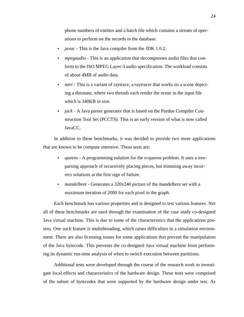
24
phone numbers of entities and a batch file which contains a stream of oper-
ations to perform on the records in the database.
• javac - This is the Java compiler from the JDK 1.0.2.
• mpegaudio - This is an application that decompresses audio files that con-
form to the ISO MPEG Layer-3 audio specification. The workload consists
of about 4MB of audio data.
• mtrt - This is a variant of raytrace, a raytracer that works on a scene depict-
ing a dinosaur, where two threads each render the scene in the input file
which is 340KB in size.
• jack - A Java parser generator that is based on the Purdue Compiler Con-
struction Tool Set (PCCTS). This is an early version of what is now called
JavaCC.
In addition to these benchmarks, it was decided to provide two more applications
that are known to be compute intensive. These tests are:
• queens - A programming solution for the n-queens problem. It uses a tree-
parsing approach of recursively placing pieces, but trimming away incor-
rect solutions at the first sign of failure.
• mandelbrot - Generates a 320x240 picture of the mandelbrot set with a
maximum iteration of 2000 for each pixel in the graph.
Each benchmark has various properties and is designed to test various features. Not
all of these benchmarks are used through the examination of the case study co-designed
Java virtual machine. This is due to some of the characteristics that the applications pos-
sess. One such feature is multithreading, which raises difficulties in a simulation environ-
ment. There are also licensing issues for some applications that prevent the manipulation
of the Java bytecode. This prevents the co-designed Java virtual machine from perform-
ing its dynamic run-time analysis of when to switch execution between partitions.
Additional tests were developed through the course of the research work to investi-
gate local effects and characteristics of the hardware design. These tests were comprised
of the subset of bytecodes that were supported by the hardware design under test. As

25
such, the tests themselves are relatively small in size, but are focused on the features they
exercise. These tests are:
• Loop counter - A simple for loop used to gauge maximal performance
increase.
• Fibonacci - An iterative program that will compute the nth Fibonacci num-
ber.
• Ackerman - A recursive program that will compute the Ackerman function
for a given input combination.
• Bubble sort - Uses the bubble sort algorithm to sort an array of numbers.
This test examines the effects of increased bytecode size.
• Insertion sort - Implementation of insertion sort algorithm used to analyze
the effects of high levels of memory access.
Each of these tests is chosen to examine specific design issues that will be presented later
in the dissertation.
2.7 Summary
This chapter presents the idea of co-designed virtual machines and its motivation.
The chapter began with a brief description of virtual machines and some of the motiva-
tion for virtual machines usage. Several current implementation methods for virtual
machines were presented along with their advantages and disadvantages. The discussion
continued with a description of some of the benefits offered by co-designed virtual
machines over these current methodologies. The chapter concludes discussing the Java
platform and the decision behind choosing the Java virtual machine for the working
example. The next chapter addresses some of the underlying information and research
that has been done in the areas of hardware/software co-design, reconfigurable comput-
ing, and virtual machines in general.

26
CHAPTER 3
Hardware/Software Co-Design Chapter 3
3.1 Introduction
To provide a context for the research work to be presented later, this chapter pre-
sents a short background survey of hardware/software co-design. The concept of hard-
ware/software co-design is defined and the issues that make co-design important are
discussed. This leads into an overview of reconfigurable computing including the various
types of reconfigurable computing and a common device used to implement reconfig-
urable computing, Field Programmable Gate Arrays (FPGAs).
3.2 Hardware/Software Co-Design
Hardware/Software co-design is the integrated design of systems implemented
using both hardware and software components [25]. Systems that consist of both compo-
nents are not new, but methodologies for designing these systems are new. Software pro-
vided for such systems is often written using instance specific techniques and is now
being seen as a specific topic for software engineering [70]. These methodologies are
used to concurrently apply and trade off design techniques from both computer and soft-
ware engineering disciplines [86,89]. The approaches are intended to give relief to
designers struggling with instance specific divisions of hardware and software compo-
nents, and the resulting integration problems. Their purpose is to streamline the design
process, thus reducing design costs and shortening time-to-market; to optimize the hard-
ware/software partitioning, thus reducing direct product costs; and to ease integration, by
automatically generating hardware/software interfaces [87].
There has been a growing interest recently in co-design for several reasons. The
first reason is in the advances in technologies and the tools used in developing hardware
and software components. New technologies for system-level specification and simula-

27
tion environments, formal methods for design and verification, prototyping techniques,
and computer-aided design frameworks have created new possibilities for co-design
research [73,46]. A second reason is the competitive market in which co-designed sys-
tems exists. Two factors at the forefront of system design are reduced time to market and
optimization of costs [67]. These factors have emerged to become vital constraints in the
realization of many systems. Finally, the growing diversity and complexity of systems
that are being created with hardware and software components is an additional reason for
the interest in co-design methodologies [118]. The embedded systems market is the pri-
mary beneficiary of co-design methodologies and it has grown tremendously in recent
years. New applications such as video game consoles, cellular phones, digital cameras,
handheld computing devices, and DVD all contribute to the drive in the embedded market
[91]. With this growth in applications comes the need for better methodologies for co-
design.
Hardware/Software co-design is different from conventional hardware design or
software design approaches in that it brings the development cycles of both hardware and
software together into a joint process [67,120,87]. With traditional development of sys-
tems consisting of both hardware and software components, the process is split into two
development flows as depicted in Figure 3.1. The requirements and specification of the
system are jointly performed at a high level. The focal point of this step is what the end
system will be. Questions such as: “What are its capabilities and functionalities?” are
answered. Only preliminary decisions concerning which components of the system will
be delivered through hardware and software and broad technology-based decisions are
made. After this stage however the design process splits. The high-level components to
be supported in hardware are themselves designed independently from the software com-
ponents and vice versa. Each of these components often are designed, implemented, and
tested in seclusion from the other design flow. Only after their individual completion is
the attempt made to integrate the components. Quite often, the integration can require the
near complete re-design of a component to accommodate the other components.
This strategy has several flaws. An obvious concern with this is the unpredictable
schedule for product delivery and cost overruns. How well the components come together

28
at the end of the process can drastically affect meeting deadlines and cost measurements.
With no knowledge of the component integration until the end, predicting these are
extremely difficult, if not impossible. For example, an incorrect decision during the speci-
fication of the hardware platform may result in software having to compensate for short-
comings of the hardware design [85]. Decisions made during the software design affect
those of the hardware design, and vice versa. It is also possible that the software compo-
nents design is not sufficient. Poor software performance at the integration stage may
result in requiring extra hardware support [67].
The most important flaw of this approach is that of ignoring the relationship
between the hardware and software components. Co-design focuses on identifying and
exploiting these relationships to assist the design process by providing a unified view of
the system through all phases of the design [93]. In a closed environment, each of the sep-
arately designed components can function properly and to the original desired specifica-
tion. It is in the integrated environment, where interaction between the components is
necessary and critical that the success or failure of a design is measured. Co-design
focuses on the importance of this integration, while traditional methods are unaware of its
importance. An example of this is the ability to shift components across the hardware/
software boundary during the design process. As can be seen from Figure 3.1, following a
Figure 3.1 Traditional hardware/software development.
SystemRequirements/Specification
Software Requirements
Analysis
HardwareRequirements
Analysis
Hardware Design &
Test
Software Design &
Test
SystemIntegration

29
traditional methodology, there are no opportunities to shift functionalities until the inte-
gration stage where typically shifting components is too costly. Using a co-design meth-
odology, revisiting initial decisions on partitioning is easier and more possible [120]. This
provides opportunities for seeking the optimal system solution.
A conventional approach to hardware/software co-design would see the separation
between hardware and software occur as late as possible. This results in avoiding the
caveats that were seen in the previous approach. Figure 3.2 depicts a common conven-
tional approach for co-design [87]. As one can see, the system co-design process only
splits at the necessary point where the implementation takes place. This is necessary as
current implementation tools do not sufficiently support both hardware and software
SystemRequirements
SoftwarePartition
Interface
Hardware/SoftwarePartitioning
HardwarePartition
Co-Simulation
IntegratedSystem
Figure 3.2 A conventional co-design methodology.

30
component development. There are trends towards co-specification languages which will
unite this division in design flows, but for the present time these must remain separate
[49,50]. Even when this co-design flow separates, there is a connection between them
through the interface. This is intended to safeguard against the hardware and software
becoming divided and supports an easier integration of the completed implementation.
3.3 Issues Involved with Co-Design
Within hardware/software co-design, four main areas of research have emerged:
modeling, partitioning, co-synthesis, and co-simulation [25,67,87,26]. The following sub-
sections discuss each area and the challenges they present.
3.3.1 Modeling
There exist many modeling styles to describe and encapsulate a digital system
[37,120,87,14,42]. These various styles are required due to the complexity of the systems
being modeled, and the need to model various aspects. Functional modeling of digital
systems is often done using various programming languages, like C, C++ or Java. These
models are used to verify properties of the system and attain measurements of quantifi-
able properties of the system such as performance and cost. The drawbacks of these mod-
els is that they are often too generic to represent digital hardware and thus fail to fully
capture the specification [25]. Specification models are used to describe the required
behavior of the system. There are a large number of modeling schemes, both graphical
and textual, ranging in degree of abstraction for accurately specifying a system. Some of
these include Statecharts, VHDL, Verilog, or Esterel (just to name a few) [44,7,106,13].
Between these, there exist modeling tools that attempt to provide various degrees of both
functional and specification modeling.
The major issue in this area is providing a suitable methodology for modeling the
target system and a methodology that is beneficial for other stages of the co-design pro-
cess. Many techniques exist to support specification and design of hardware or software,
but typically these techniques apply to homogeneous components, either hardware or
software, but not both. Some researchers favor a formal language which can yield prov-

31
ably correct code. But most prefer a hardware-type language (e.g., VHDL, Verilog), a
software-type language (C, C++), or other formalism lacking a hardware or software bias
(such as Codesign Finite State Machines) [25]. New languages and support for existing
modeling technologies are being introduced that reduce the design step from modeling to
implementation. This can be seen through developments with System-C and hardwareC
[50,66].
3.3.2 Partitioning
With a co-designed system there are two parts, namely hardware and software.
Determining the division of components and functionality of the system between each is
a non-trivial task. This partitioning of the system between hardware and software can dra-
matically affect the end characteristics of the co-design, and decide whether the co-design
succeeds or fails to meet the specification requirements. Constraints such as cost, perfor-
mance, size, power, and other resources demonstrate the trade offs between shifting com-
ponents between the two partitions. Dependent upon the priority of each constraint,
decisions are made regarding which partition a system’s functionality shall exist.
There are in general three different ways of approaching the partitioning problem.
The first approach involves starting with a software description, or implementation, of the
system and selectively migrating components of the system to hardware until the desired
constraints are met. Secondly, partitioning can begin with a hardware description, or
implementation, of the system and can easily shift functionality of the system to software
until a suitable solution is attained. In the last approach the partitioning can be based on a
generic description that is neither hardware nor software based, but rather a specification
of the system’s behavior. From this, heuristics are used to divide the system between the
two partitions. Primarily, systems are co-designed starting from one of the first two sce-
narios. Two common tools that are used to aid in the partitioning are Vulcan and Cosyma,
both incorporate the first and second approaches respectively [120,42].
Through either approach there are several factors that affect the decision as to
which partition a functionality will exist in. Some of these factors are timing constraints,
physical constraints (such as power and design space), component cost, availability of
common off the shelf components, and time to market [37]. The importance of each fac-

32
tor is dependent on the specific system being partitioned.
All of these approaches involve iteration of the partitioning process. With the high
number of factors affecting the cost and performance there are many variables that must
be accounted for, so many that obtaining an optimal partition directly from the original
design is not common. The fine-tuning of the partitioning occurs through iteration. Itera-
tion allows the designers to focus on specific characteristics and fine-tune the co-design
towards the optimal solution. This does not imply that the original co-design is fruitless,
it is just that the original design provides an initial partitioning for the process to start,
and the iteration improves the design to its optimal point.
Research in this area is focusing on providing partitioning strategies to find the opti-
mal division between hardware and software with an initial partitioning scheme. This is a
difficult problem due to the varying types of systems to be co-designed and their proper-
ties. There are instances where the partitioning is trivial, such as the need for a floating
point component in a cash register system. This type of functionality is easily provided
through hardware and can be reused from other pre-existing floating point units and there
is presumably no shortage of space or power. This is not the case however when the same
functional component is required for a cellular telephone. There are different constraints
on power and space, and therefore the partitioning is likely different.
3.3.3 Co-Synthesis
With a specification of the system, and a partitioning scheme, the next step is to
design an implementation. A co-synthesis approach for hardware begins with systems
described at the behavioral level by means of an appropriate specification language. The
co-synthesis attempts to provide a mixed hardware/software implementation of the sys-
tem using synthesis techniques. Co-synthesis for system implementation provides sys-
tematic and rapid evaluation of various implementation alternatives. System cost and
performance trade offs dictate a choice between a synthesized hardware and software
implementation for various components. Having the system described through a generic
specification, allows for the design to be systematically analyzed for trade offs, and thus
finding the optimal design consisting of hardware and software components [42].
33
The choice of a suitable specification language for digital systems from which to
perform co-synthesis is a subject of on-going research. There are traditional methods for
carrying out this process all in hardware (VHDL, Verilog) or all in software (C, C++) sys-
tems, however there is no clear process for a co-designed system. This is due to the added
complexity of the interface between the hardware and software partitions, and the under-
lying technologies between hardware and software synthesis. Hardware systems have
computer-aided design (CAD) tools available for synthesizing hardware designs speci-
fied in languages such as VHDL and Verilog. Software systems have compilers available
to synthesize systems described in various programming languages such as C and C++. It
is providing the co-synthesis tool capable of bringing these together to attain a correct
interface that is the challenge.
New languages such as hardware-C, SpecC, and SystemC are being researched that
provide support for describing both hardware and software components as well as support
the synthesis of both [66,38,50]. An obvious advantage is allowing a designer to specify
the complete system using a single specification tool. The co-synthesis capability allows
the designer to easily shift components between hardware and software during the co-
design process without having to re-specify the component in a different manner to corre-
spond to the underlying implementation. This allows cost efficient exploration of the par-
titioning and eases the implementation process.
3.3.4 Co-Simulation
Co-simulation combines the simulation of software components running on a hard-
ware processor with the simulation of dedicated hardware components. Co-simulation is
especially difficult given the issues of scheduling and timing that exist between them.
Simulation provides a means to verify correctness to the original system specification and
requirements as well as a way of uncovering design flaws. This is especially true for co-
designed systems where the costs of debugging the system can be drastically reduced in a
co-simulation environment and the results may be fed back to the partitioning step for
further refinement of the systems partitioning and subsequent steps. The key difficulty of
co-simulation is to simulate the hardware components. A fine-grained simulator of the
hardware will result in a simulator which is too slow. A simulator that is too coarse-

34
grained will not be precise enough to accurately simulate the system. Thus, the problem is
to couple models at different levels of abstraction such that the overall simulation is suffi-
ciently precise [26].
There are many tools available for co-simulating systems. One such tool is Ptolemy,
a heterogeneous simulation and design environment supporting multiple models of com-
putation. It supports dataflow, discrete-event, process networks, synchronous/reactive,
and finite-state machine models of computation [47]. Ptolemy is an object-oriented
approach that treats each model of computation as an object, and these objects communi-
cate through discrete events [26].
Recent trends in co-simulation are towards emulation. As previously mentioned, co-
simulation can be a slow process. With systems becoming larger, this problem is becom-
ing a greater concern. Emulation attempts to solve this problem by using a real prototype
of components in place of simulated components. This is feasible due to the increasing
size, speed and availability of Field Programmable Gate Arrays (FPGAs) and Digital Sig-
nal Processors (DSPs) [16,28,115]. These allow designers the capabilities to rapidly pro-
totype their custom hardware components at speeds much faster than simulation, and
sometimes as fast as the final implementation. Ongoing research in this area is directed
towards automating the emulation process [88,121].
3.4 Reconfigurable Computing
Reconfigurable computing exploits configurable computing devices, such as Field
Programmable Gate Arrays (FPGAs), so that they can be customized to solve a specific
application [23,45]. Due to its potential to greatly accelerate a wide variety of applica-
tions, reconfigurable computing has become the subject of a great deal of research. Its
key feature is the ability to perform computations in hardware to improve performance,
while maintaining the flexibility of a software solution. This flexibility is key as it
reduces the costs in comparison to a custom application specific integrated circuit (ASIC)
when changes to the system are required. Traditionally, systems were implemented in
either hardware, software, or both but kept very distinct. In hardware, the system may

35
consist of a custom designed ASIC. Because the ASIC was designed specifically for the
given system, the computation would be fast. The trade-off for this is the difficulty
encountered when the ASIC needs to be changed to reflect changes to the system require-
ments. The flexibility is more important than ever now due to the speed-to-market factor
driving industry [12].
In software, a microprocessor is utilized that executes a set of instructions. Having
the application described through an encoding of these instructions provides a means of
making the hardware more general and thus usable for more applications. However, the
downside of this flexibility is that the performance suffers and may be below that of a
custom ASIC. The microprocessor must read each instruction in the application, deter-
mine its meaning, and only then execute it. When both were used to implement a system,
traditionally they were kept distinct, such as in a desktop station. Both hardware and soft-
ware were designed and implemented independently and only later would they come
together through some instance specific interface. Reconfigurable computing is intended
to fill the gap between hardware and software. Achieving potentially much higher perfor-
mance than software through custom hardware design, while maintaining a higher level
of flexibility than a custom ASIC through reconfigurability. The key importance of this
approach is the unified design and implementation of the system providing a good inter-
face and a superior end system in terms of performance and maintainability.
Reconfigurable computing utilizes technologies that make the hardware platform
re-programmable. This re-programmability provides the flexibility of software as men-
tioned earlier, while still maintaining a higher level of performance than the software
implementation. There are some trade-offs between having an ASIC and a re-programma-
ble device. ASICs typically provide a lower cost per unit than their re-programmable
counterpart and are often times easier to design due to their lack of flexibility [11]. Nev-
ertheless, these trade-offs are often times suitable for the gains in flexibility.
For a given application, it is commonly said that 90% of the execution time is spent
in 10% of the application’s code. By targeting these areas within an application, hard-
ware support can dramatically increase performance in comparison to a software imple-
mentation [15]. Typically ASICs, being used as co-processors, are dedicated to support

36
specific operations or implement a critical loop while exploiting the local parallelism.
Whereas ASIC co-processors provide acceleration for specific applications, co-processors
based on reconfigurable hardware can be applied to the speed-up of arbitrary software
programs with some distinctive characteristics. This has been used to accelerate many
different applications in domains such as multimedia and mathematical problems
[26,108,82]. The next section describes two classifications that have emerged for recon-
figurable computing.
3.4.1 Types of Reconfigurable Computing
There are two types of reconfigurable computing that are characterized based on the
manner in which they utilize the reconfigurable computing device. The first type, which
is most broadly used, is compile time reconfiguration [84]. This is when the configura-
tion of the computing device is decided at compile time. In this environment, the recon-
figurable device is programmed at the beginning of execution, and remains unchanged
until the application has finished. The second type of reconfigurable computing is run-
time reconfiguration. In this computing paradigm, the application consists of a set of
tasks that can be downloaded into the reconfigurable device. During the execution span of
the application, the reconfigurable device is re-programmed a number of times from the
set of tasks. Both of these types of reconfigurable computing are commonly implemented
using field programmable gate arrays, which are described in the following section.
3.4.2 Field Programmable Gate Arrays
Field Programmable Gate Arrays (FPGAs) consist of an array of logic blocks that
can be connected by general interconnect resources, as depicted in Figure 3.3 [16]. Each
of the logic blocks within the FPGA are capable of implementing a 4-input function
through the use of a look-up table, or acting as a small register. The interconnect com-
prises of programmable switches that serve to connect the logic blocks to one another.
The I/O cells are used to connect the FPGA to an external device for communication.
Logic circuits are implemented in the FPGA by first partitioning the logic circuit into
smaller components, such that each piece can be implemented by a single logic block.
From this, each of the smaller logic circuits are placed within logic blocks on the FPGA

37
architecture such that they can later be connected to reassemble the original logic circuit.
Each of the components within the FPGA are re-programmable, thus allowing the user to
repeat the process of creating circuits and mapping them to the FPGA.
The design process for FPGAs is aided through the use of various Computer Aided
Design (CAD) tools. These tools allow the designer to describe the design using various
specification formalisms such as VHDL, Verilog, state machines, or other proprietary lan-
guages [7,106,53,48]. Using this specification, the tools perform synthesis of the design
to generate a gate-level description of the system. This is followed by place and route
tools which fragment the design into the FPGAs basic logic components and determines
optimal interconnecting schemes. Finally, the tools provide utilities for communicating
the design to the FPGA device for re-programming [53,48].
Traditionally FPGAs were used primarily for verification and validation. A designer
could quickly prototype their designs in hardware to check that the design met the specifi-
cation and provides a correct solution. Through this use, it is unnecessary, until the final
stages of prototyping, to ever fabricate the hardware design being developed. This drasti-
Figure 3.3 A conceptual field programmable gate array (FPGA).
I/O CellLogicBlock
Interconnect

38
cally reduces both the cost and time of hardware development [11]. In recent years, both
the performance and capacities of FPGAs have grown such that they can now be used to
implement many end products. FPGAs are increasingly being used in cellular telephone
development and in other products [53]. While the process of moving the FPGA into
commercial products has been used in embedded systems for a while, it is only now
beginning to be used in non-embedded computing.
3.5 Summary
This chapter discussed several topics in connection with the research work to be
presented in this dissertation. Hardware/software co-design was introduced and the moti-
vation behind its importance and some of the challenges that are currently being
researched. The new emerging field of reconfigurable computing and the potential impact
that this computing paradigm offers was discussed. The next chapter begins the in-depth
discussion of the co-design methodology, specifically concerning the partitioning of the
virtual machine between hardware and software.
CHAPTER 4
Co-Design Partitioning Chapter 4
4.1 Introduction
This chapter describes the research involving the virtual machines specification to
determine what portion of a virtual machine should be implemented in hardware and
what should be implemented in software. Decisions made during the partitioning must
consider several factors and emphasize the importance of each in the decision process.
These factors include hardware design space, physical hardware computing speed, and
the interface between the hardware and software components. For example, how much
data traffic, both in terms of volume and frequency, will have to be exchanged between
hardware and software, given a partitioning scheme? The capabilities of the underlying
communication rate and cycle time can determine whether a partitioning scheme will suc-
ceed or fail.
The following section describes the factors involved and the basis upon which the
partitioning is performed. Subsequent sections describe the partitions that result from
applying the approach to the Java virtual machine.
4.2 The Process of Partitioning
Every system when partitioned has two general competing optimizations: perfor-
mance and cost. For this work the larger the portion of the system that is implemented in
hardware, the faster the system and more expensive the implementation becomes. Con-
versely, given a targeted platform there are no fabrication costs, other than those of devel-
opment, associated with designing and implementing the full virtual machine in software.
To provide hardware support there is the additional cost of the physical hardware
device(s). The more hardware support required, the higher the costs. As each functional-
ity is shifted from software to hardware, the demands on physical design space in the
40
hardware device increase.
As discussed in chapter two, partitioning strives to assign functionalities to be sup-
ported in hardware or software to satisfy the overall system requirements. The partition-
ing approach used must be aware of the specific considerations of the system that
contribute to both the cost and performance. Additionally, the partitioning process must
be knowledgeable of the acceptable levels of both cost and performance to obtain a satis-
factory solution.
For this research, the focus of concern is the potential increase of performance that
can be gained by a co-designed virtual machine. With this main goal, the partitioning
approach focuses on providing performance improvements. While special attention is
required concerning the underlying resources, this dissertation does not focus on the spe-
cifics of the necessary resources required. It has been decided to address the potential
shortfall in resources under different underlying architectures by providing various con-
figurations of the virtual machine. This solution allows the end user to determine the
acceptable trade-off between cost and performance, especially important given the rang-
ing sizes, speeds, and costs of reconfigurable hardware and its supporting board environ-
ment.
4.2.1 Partitioning Approaches
When investigating a virtual machine for co-design, there are three different
approaches from which the process can be undertaken. These correspond to the three
approaches for co-design in general as discussed in subsection 3.3.2. They are co-design-
ing from 1) a specification of the virtual machine; 2) an existing software only implemen-
tation of a virtual machine; or 3) a hardware only implementation of the virtual machine.
Each of these different starting points for the co-design process work under the same
basis of shifting features and support of the virtual machine between eventual hardware
and software components. As discussed previously, each of these will provide a starting
point for the partitioning scheme and will potentially later undergo several iterations of
fine tuning with shifting functionalities between hardware and software. The only key
difference is in the situation when a feature provides negligible improvements under each
partition. In this case, reuse may play a factor in deciding to leave the support under the
41
existing partition. For example, if a software implementation of a virtual machine existed
and a given functionality provides no significant improvement in hardware over soft-
ware, then leaving the functionality in software may be more appropriate since reuse of
the software implementation may be possible.
While the third scenario is foreseen to be formidable for transforming current hard-
ware platforms into virtual ones, with systems becoming legacy and software applications
still available for the platform, it may be desirable to transform the platform into a co-
designed virtual machine. In this case, the co-design process can begin from the current
available form of the virtual machine.
4.2.2 Exploitations of Virtual Machine Partitioning
When partitioning a virtual machine between hardware and software there are cer-
tain characteristics and properties that the partitioning strategy can focus upon to achieve
a suitable initial partitioning. Most virtual machines are comprised of two parts: a low
level instruction set that is executable by the underlying hardware architecture, and a high
level operating system to perform system maintenance, such as thread and memory man-
agement. Since part of the virtual machine is high level operating control, it is undesirable
to partition this work into hardware due to the requirements of the operations. While this
is not true for all co-designed systems, for virtual machines high-level operating control
typically requires access to all devices in the system, something that is not common with
the use of programmable devices in desktop workstations. Additionally, some operations
require considerable data flow and control that is too vast to be supported in a hardware
environment with restricted design space. This is true in general partitioning methodolo-
gies for co-designed systems where operations closely linked to the operating system and/
or user programmability (especially in embedded systems) should remain in software.
When partitioning from a software implementation, often the division between the hard-
ware architecture and high level operating system is unclear due to both being integrated
together. This leads to the task of investigating the low level instruction set to determine
what is suitable for implementation in hardware.
A virtual machine instruction set contains operations and characteristics that are
found in traditional processors. To implement part, or all, of this in hardware is desirable
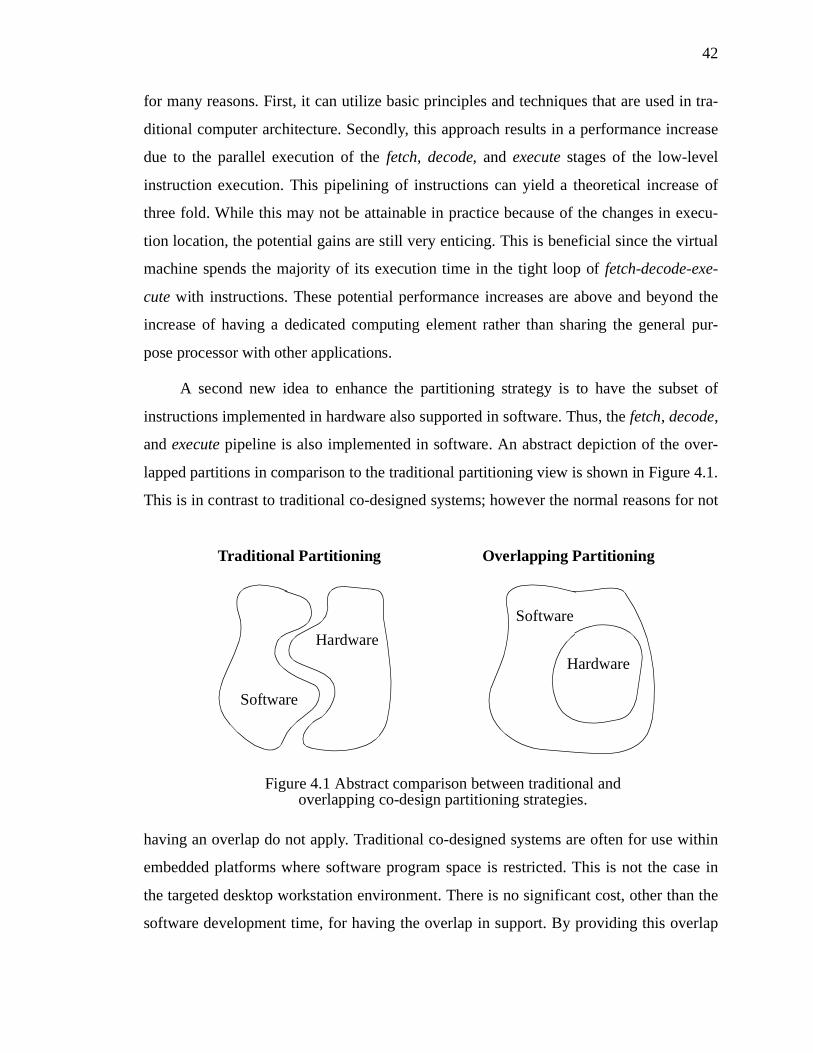
42
for many reasons. First, it can utilize basic principles and techniques that are used in tra-
ditional computer architecture. Secondly, this approach results in a performance increase
due to the parallel execution of the fetch, decode, and execute stages of the low-level
instruction execution. This pipelining of instructions can yield a theoretical increase of
three fold. While this may not be attainable in practice because of the changes in execu-
tion location, the potential gains are still very enticing. This is beneficial since the virtual
machine spends the majority of its execution time in the tight loop of fetch-decode-exe-
cute with instructions. These potential performance increases are above and beyond the
increase of having a dedicated computing element rather than sharing the general pur-
pose processor with other applications.
A second new idea to enhance the partitioning strategy is to have the subset of
instructions implemented in hardware also supported in software. Thus, the fetch, decode,
and execute pipeline is also implemented in software. An abstract depiction of the over-
lapped partitions in comparison to the traditional partitioning view is shown in Figure 4.1.
This is in contrast to traditional co-designed systems; however the normal reasons for not
having an overlap do not apply. Traditional co-designed systems are often for use within
embedded platforms where software program space is restricted. This is not the case in
the targeted desktop workstation environment. There is no significant cost, other than the
software development time, for having the overlap in support. By providing this overlap
Software
Hardware
Hardware
Software
Figure 4.1 Abstract comparison between traditional and overlapping co-design partitioning strategies.
Traditional Partitioning Overlapping Partitioning

43
of instruction support between the two partitions, there is added flexibility to how an
application is executed in the virtual machine. As will be discussed later, by overlapping
the instruction support, the virtual machine can avoid the situation of thrashing by contin-
uously transferring execution control between the two computing elements. With some
additional control logic, it also provides the greater potential of parallel execution
between the two computing elements. With this approach it is possible for two threads to
run in parallel provided one of the threads can execute during this time frame with the
instruction subset supported in hardware. Though beyond the scope of this dissertation,
this outlook promotes future research for parallelism. This is discussed in greater detail in
section 8.3 of the dissertation.
4.2.3 Partitioning Heuristics
The partitioning approach employed here is intended to be extendable to many vir-
tual machine platforms. In general, two questions must be answered to decide if an
instruction should be provided in the hardware partition.
1. Is the instruction more efficiently implemented in hardware than software?
2. If yes, is the instruction suitable to be implemented in hardware?
For both of these questions, the answers are dependent on the criteria used to define
“efficiently” and “suitable”. These criteria consist of such factors as cost, power, perfor-
mance, design space, and memory.
To aid the partitioning process, the following guidelines can be used to identify
instructions for implementation in hardware. These guidelines are advisory and there may
exist virtual machines for which these guidelines may not be entirely applicable.
1. Depending on the criteria of importance to the implementation, “efficient”
has different meanings. In this discussion, performance (or speed) is the
main criterion. The answer to this question is important in deciding to pro-
vide an instruction implementation in the hardware partition. If the instruc-
tion implemented in software performs significantly slower than the
equivalent hardware implementation, then inclusion in the hardware parti-
tion is suitable. In the instance where software and hardware implementa-

44
tions provide comparable performance, one must consider other factors, for
example, the available design space and if inclusion in either partition will
significantly contribute to or degrade pipelining.
2. Instructions in hardware can only perform operations requiring limited
memory. Limited memory in this sense refers to both the space and speed
of the memory. The instruction should only require data that can be stored
in data spaces that are accessible to the hardware partition. Instructions that
need access to only the temporary register space for intermediate values or
cached local variables are candidates for hardware implementation. It is
also possible to implement instructions in hardware that use the overall
data pool. This is dependent on the support to allow such access. If the
capability is available and the penalty for memory access is not too great, it
can be desirable. Likewise, the time needed to access the data from mem-
ory should be considered as part of the instruction’s execution time.
3. Instructions chosen for hardware implementation should execute only a
predictable and simple task. The selection of instructions under these con-
ditions allow the hardware design to be capable of predicting the execution
flow of instructions and to utilize pipelining. An instruction’s simplicity is
based on the area required to implement the instruction in hardware.
Choosing simple instructions ensures a small resource requirement for
instruction support. These instructions will not need a large design area,
eventually resulting in the capability of the hardware part to support a large
number of instructions.
4. At the time of partitioning, the specific characteristics of the physical
resources are often unknown. This includes such characteristics as speed
and size of the available design space and memory resources. In the situa-
tion where the details of available resources are known, this aids by giving
an indication of any preferences for trade-offs in decision making. Any
resource limitations that exist must be considered in conjunction with the
other guidelines.

45
From these guidelines, several general classes of instructions can be identified that
are found in most architectures and are more often suitable for implementation in hard-
ware. These general classes of instructions are:
• Constant Operations - This class of instructions perform fixed operations
that are used for mainly setting and initializing data. Examples of such
instructions are set_zero, set_one, set_negative_one, and nop (no opera-
tion).
• Primitive Casting Operations - Instructions that facilitate the conversion
of one basic type to another compose this class. Basic types that are found
in most virtual machines include integer (long and short), character, float-
ing-point, double precision, and reference.
• Primitive Comparison Operations - Instructions that compare primitive
data types and stores the result make up this class. Examples of such opera-
tions include: compare_integer, compare_character, compare_float, and
compare_double.
• Program Flow Control - This class is composed of instructions that alter
the program counter such as (un)conditional branch statements. An exam-
ple of such an instruction is goto and branch_if_equal.
• Arithmetic Operations - This class of instructions provide the support of
performing arithmetic operations such as addition, subtraction, multiplica-
tion, division, remainder, and modulo on different primitive types.
• Logic Operations - Instructions that perform Boolean logic operations on
data compose this class. Boolean logic operations typically supported
include and, or, not, xor, nor, and nand.
• Register Manipulation - Each virtual machine typically has a small tem-
porary scratch space where results from intermediate operations are stored
during execution. In traditional hardware architectures, this is typically a
register set. Instructions in this class include support for reading, writing,
copying, and moving the values in this temporary space.

46
• Execution Frame Manipulation - Beyond the temporary scratch space,
there is often a local context within which the operations are performed.
This context, referred to as a frame, provides data that is crucial for execu-
tion such as local variables. An equivalent set of instructions comparable to
register manipulation are typically available.
To clarify the discussion, the partitioning strategy described will be applied to an
example virtual machine, the Java virtual machine. As discussed in section 2.5, this will
allow for a later insight into the potential coverage and implementation effects of the
strategy being used. Appendix A shows several quantitative results obtained from profil-
ing execution of several benchmarks within the Java virtual machine. These results can be
used to assist in decisions throughout the partitioning process while applying the guide-
lines previously presented.
The next two sections describe the software and hardware partitions of the Java vir-
tual machine. The discussion focuses on the components of the system that are provided
within each partition and the justification. While it is necessary to focus on details and
specific instructions for the Java test case, the discussion does highlight generic instruc-
tion groups and features that should be supported by hardware or software in particular.
4.3 Software Partition
The software partition naturally includes the high level operating system support for
the virtual machine, but it is also necessary for software to be responsible for providing
support for bytecode instructions that cannot be implemented in hardware for various rea-
sons. Additionally other instructions, or groups, that are more suitably implemented in
software are listed below as well as additional software components that are needed to
support the hardware partition. It can be seen that these instructions are rather complex,
but their execution frequencies are rather low [35]. The following subsections describe
each of the groups of instructions partitioned into software only and their justification.
4.3.1 Loading Data from the Constant Pool
When performing a load operation from the constant pool, it is possible that the
47
class being referenced is not yet loaded into the virtual machine. Part of the loading of a
class into the virtual machine requires the class to be read from storage, either from a file-
system or through the network, verified for security purposes, and then lastly stored into
the virtual machine’s memory (which may result in intervention from the garbage collec-
tor). The opcodes 018 - 020 are for resolving the classes required before performing the
constant pool loads to memory. Since these instructions require execution from the host
processor, it is more beneficial to switch the execution to the host for all the computa-
tion. Once the classes are resolved, then future loads from the constant pool can use the
quick versions which are implemented in hardware.
4.3.2 Field Accesses of Classes and Objects
Accessing data fields in classes and objects is not a trivial process. This is due to the
same issues of class loading and verifying that can occur when accessing the data pool.
As such, getstatic, putstatic, getfield, and putfield (opcodes 178 - 181 respectively)
should remain in the software partition.
4.3.3 Method Invocation
This applies to instructions 182 - 185, namely invokevirtual, invokespecial, invoke-
static, and invokeinterface. Method invocation instructions which require the loading of
the class into the virtual machine are better implemented in software. This is due to the
required processing by the host processor to load and verify the class needed. In addition,
with the invocation of a new method, the state of the calling method must be stored for
return to the method. Likewise, the new method’s bytecode must be loaded for execu-
tion. This is an especially hard problem if the hardware and software partitions do not
share the same memory space.
4.3.4 Quick Method Invocation
These are the opcodes 214 - 219 and 226, namely invokevirtual_quick,
invokenonvirtual_quick, invokesuper_quick, invokestatic_quick, invokeinterface_quick,
invokevirtualobject_quick, and invokevirtual_quick_w (for wide index). Unlike other
quick instructions which can be implemented in hardware after the class is known to be
loaded, quick method invocations cannot be implemented in hardware. This is due to the

48
complexities of storing and changing the machine state between methods. Despite the
method being resolved, this problem still exists in the quick version.
4.3.5 Exceptions
Exceptions are a very complex mechanism to implement in any platform. The rea-
son for this is the effect that an exception can have on the calling stack and the flow of
execution. When an exception is thrown it signals that something out of the ordinary has
happened. The actions taken by an exception vary between instances. They could range
from a simple print message, to as intense an error as the entire application exiting.
Within the virtual machine it could involve unwinding several calling stacks to find a
location where the exception is handled. An exception in Java also involves the creation
of an Exception object that is passed back to the location where the exception is caught.
This can result in class loading and verifying as part of the exception throwing process.
As a result of this complexity, the instruction athrow (opcode 191) is implemented in
software where manipulating the execution stack is more easily performed.
4.3.6 Object Creation
Creating objects in the virtual machine can be a very complex process. During the
creation of the object it may be necessary to load and verify the class of which the object
is an instance. If the object is a thread object, then the object has to be added into the
thread scheduling of the virtual machine so that the thread will have the opportunity to
obtain time slices and to have an execution environment created. To make the process
still more complex, it is possible that during the creation of the object an exception may
have to be thrown to signal a shortage of memory or that the class description cannot be
found. This all adds an enormous amount of complex processing to create an object.
Since the creation involves direct interaction with the software support in terms of excep-
tions and thread handling, the creation of objects should be done in software. As such the
instructions new and new_quick (opcodes 187 and 221) are implemented in the software
partition.
4.3.7 Array Creation
Creating an array is as complex a process as creating a single object. During the cre-
49
ation it is possible that an exception can be thrown due to a lack of memory or other
resources. As such it was decided to implement the instructions newarray, anewarray,
multianewarray, anewarray_quick, and multianewarray_quick (opcodes 188, 189, 197,
222, and 223 respectively) in software. The differences between the quick and non-quick
versions of the instructions is only that for the quick version, the class has already been
loaded and verified in the virtual machine. This solves some complexity, but still allows
for a lack of resources which can cause an exception.
4.3.8 Storing to a Reference Array
Java is a strongly typed language, and this is exemplified when storing a reference
into a reference array. Opcode 083, aastore, checks the reference before storing it into the
array to verify that the object reference is a correct type, or subtype, of the array. This is
an intense process that involves tracing through the subtype hierarchy to determine that
the class is a descendant of the array type. This is better left in software since it requires
intense usage of the whole object store for the virtual machine.
4.3.9 Type Checking
The Java virtual machine as part of its security features performs type checking on
objects to verify that any actions that cast the type of the object are legal. When checking
a type, the virtual machine must trace back through the inheritance tree of the object to
verify that the object at some point inherits that type. This tracing can involve a great deal
of work and can result in an exception being thrown. Because of this it has been decided
to implement the instructions checkcast, instanceof, checkcast_quick, and
instanceof_quick in software. This is not a major drawback as the frequency of these
instructions in relation to most applications is rather low.
4.3.10 Monitors
Monitors are the synchronization tools used within Java to ensure proper concur-
rent execution. Dealing with threads on a low level involves the ability to manipulate the
states of the threads, and to adjust their priorities. The thread manipulation support is
implemented in software due to its higher level in the overall scheme of things. Since the
instructions monitorenter and monitorexit (opcodes 194 and 195) have to deal with

50
threads in a low level fashion by accessing thread scheduling info and methods in the
higher level support, these instructions are desirable to be implemented in software.
4.3.11 Accessing the Jump Table
Two bytecode instructions implement case statement operations, where the various
cases of the instruction are arguments to the opcode. These instructions are tableswitch
and lookupswitch, opcodes 170 and 171 respectively. With the variable length of the
instructions up to a potential maximum of 234 bytes, these instructions would cause havoc
in implementing an efficient pipeline. Additionally, these instructions have a low fre-
quency of 0.032% in comparison to the other opcodes [35]. For these reasons, these
instructions are better implemented in software due to the low frequency and negative
effects on the pipelining architecture.
4.3.12 Wide Indexing
The opcode 196, wide, is used for extending a local variable index to a wide for-
mat. This instruction is better suited to the software partition for various reasons. The
instruction has multiple formats and would complicate the pipelining of instructions,
especially since one form of the instruction would result in having to lengthen the data
path from 32 bits to 48. Implementing this instruction in hardware would only show an
increase in performance in the event that the hardware partition can access the extended
area of the local variables. As well, the instruction is not frequently used. This instruction
is included in the software partition. However, with the right environment conditions, it
may be moved into the hardware partition.
4.3.13 Long Mathematical Operations
Some mathematical operations on long data types are costly in design space and are
infrequently used. This is the case for multiplication, division, and remainder (opcodes
105, 109, and 113 respectively). For this reason, they are commonly left to be imple-
mented in software as in the picoJava core [101]. This partitioning scheme allows these
opcodes to remain in software. In the event that additional design space is available, these
opcodes could potentially be moved to hardware.

51
4.3.14 Returning from a Method
Six instructions exist for returning from a method with various return types and
void, opcodes 172 - 177. These instructions affect the virtual machine by changing its
entire execution frame, including bytecode method, execution stack, local variables, and
constant pool. In the event that the hardware and software partitions do not share a com-
mon memory space, these instructions cannot be efficiently implemented in hardware. To
maintain a high level of flexibility for environments that do not share a common memory
space, these opcodes must be implemented in software. If it were known that a common
memory were always present, then these instructions could be moved to the hardware
partition.
4.3.15 Operating System Support
As for general cases, the processor itself must have some software support for man-
aging the processes executing and the resources provided. These are what make up the
operating system for the processor. In the case of a virtual machine, it too must have soft-
ware support similar to an operating system. This software support must include the man-
agement of threads, garbage collection, class verification, network and I/O support, the
Java abstract programming interface (API), and native method support. These are just
some of the necessary features which must be implemented in software to support the
Java virtual machine.
4.3.16 Software and Hardware Coordination
Just as the hardware partition needs added functionality for communicating with the
software partition, so too must the software partition have extra functionality for commu-
nicating with the hardware. This support must provide the software partition with the
ability to transfer and receive data from the hardware, signal the hardware to stop, abort,
start, and continue processes. Functionality for enhanced control needed for debugging
and testing is required.
These are some of the more specific instructions which must be supported in soft-
ware. As discussed in the previous section 4.2, the software partition also overlaps with
the hardware partition thus it includes all of the instructions in the hardware component

52
as well. This will allow for greater flexibility in migrating execution between the hard-
ware and software partitions. This is cost effective since the only penalty for having extra
support in software is the software development time.
4.4 Hardware Partition
The more instructions that can be implemented in hardware the better, since the
overall purpose of this co-design is to obtain faster execution through pipelining the
fetch-decode-execute loop. Additionally, the desire is to target the instructions that have
traditionally been supported in a typical processor to be moved into the hardware parti-
tion. It is also important to consider the usage frequency of the instructions when decid-
ing whether to implement them in hardware.
As discussed earlier, the partitioning provides several configurations with varying
levels of hardware support and resource requirements. There are three primary partitions
that have been identified for hardware partitions, with each partition being an extension
of the former as shown in Figure 4.2. These partitionings are:
• Compact - Small partition for restrictive hardware devices. Intended for
small FPGA devices, environments with a slow communication bus, or
both.
Compact
Software
Figure 4.2 Abstract view of overlapping partitioning extensions.
Host
Full

53
• Host - Extends Compact with support for accessing host memory system.
Intended for medium sized FPGA devices that have available support for
accessing the global data space of the application.
• Full - Extends Host with support for quick instructions. Specifically for the
same environment as Host partitioning scheme, however provides support
for dynamic instructions that initially require software support.
These partitioning schemes may not be suitable for all architectural environments,
however they are intended to be used as starting points for a solution. Incremental
changes to fine tune the partitioning can be easily made to add or delete instructions to
better utilize the resources available.
The next three subsections discuss the specific instructions, or grouping of instruc-
tions, that have been implemented in each of the hardware partitions, with a brief expla-
nation as to why the decision. Appendix B is a list of all the Java virtual machine
instructions. With each instruction is the opcode, mnemonic, a description of the instruc-
tion, and whether the instruction is targeted for hardware implementation or not.
4.4.1 Compact Partition
The compact partitioning, or minimal partition, encompasses the instructions that
have been targeted as fundamental instructions for execution and require minimal system
knowledge for execution. This scheme minimizes the necessary data that must be
exchanged between the hardware and software partitions for execution. Likewise, it pro-
vides a configuration with minimal hardware support. The minimal data exchange is
viewed as a potential benefit in the event that the communication medium between the
FPGA and the host system is slow. Thus, this partition is intended for environments with
a small FPGA, a slow communication bus, or both. The list of typical instruction groups
that comprise this partition are:
• Constant instructions that perform a fixed operation on no data and do not
change the state of execution other than a simple data register assignment.
• Data assignments or retrievals from the temporary register stores.
• Basic arithmetic and logic operations on local data values.

54
• Branching instructions to manipulate control flow.
• High frequency instructions.
The following sub-subsections list the specific groups of instructions that are sup-
ported by the hardware partition for the test case Java virtual machine.
4.4.1.1 Constant Instructions
Opcodes 001 through 015 represent the instructions within the Java virtual machine
that are for pushing a constant numerical on the data stack. It is very clear that an instruc-
tion that requires no computation and simply an assignment of a numerical value to a
location in memory can be implemented in hardware.
4.4.1.2 Stack Manipulation
The Java virtual machine is a stack-based computing model. This means that as
Java executes, it uses a stack to retain all data being manipulated. To allow for this model,
Java has many instructions for the purpose of manipulating the stack. These consist of
opcodes 016, 017, and 087 - 095. All of these stack manipulations can be implemented in
hardware as they translate into basic memory assignments, which are the equivalent of
instructions in traditional microprocessors for reading and writing data to registers.
4.4.1.3 Mathematical Opcodes
The opcodes 096 - 119 are for mathematical operations such as addition, subtrac-
tion, multiplication, division, remainder, and negation. Each of these operations can be
performed on the basic data types float, double, integer, and long. These instructions are
traditionally implemented in microprocessors and are easily implemented in hardware,
with the exception of the instructions discussed in section 4.3, namely lmul, ldiv, and
lrem. These instructions are implemented in the software partition since the potential
usage does not outweigh the required design space due to their low occurrence.
4.4.1.4 Shift and Logical Opcodes
The instructions for shifting numerals are opcodes 120 - 125, and logical operators
and, or, and xor as performed on integers and longs are opcodes 126 - 131. These are
implemented in hardware to increase performance.
55
4.4.1.5 Loading and Storing
The opcodes 021 - 045 and 054 - 078 are combinational opcodes for storing and
loading different types and offsets of variables from the local variables to the operand
stack. Each of these instructions are simply data copying instructions, equivalent to regis-
ter reading and writing instructions in traditional microprocessors. These instructions can
be easily implemented in hardware.
4.4.1.6 Casting Operators
The opcodes 133 - 147 allow for casting values from one primitive type to another.
For example, integer 1 to double 1.0. These operators work on the basis of mathematics
like the arithmetic operators. A clear algorithm exists for each casting operator that uses
the same basic principles similar to other mathematical operations.
4.4.1.7 Comparison and Branching Operators
The opcodes 148 - 152 are for comparison of values for greater or less than of dif-
ferent basic types, 153 - 167 are for branching from one location to another, 198 and 199
are for branching based on references being either null or non-null values, and 200 is for
an unconditional branch to a wide index. These opcodes simply change the program
counter and are implemented in hardware just as they are in other microprocessors. These
instructions are special in comparison to the other instructions as they will provide a chal-
lenge in the hardware design for pipelining of instructions.
4.4.1.8 Jump and Return
Opcode 168 is for jumping within a subroutine and opcode 201 is for jumping to a
wide index location. The opcode 169 is used for returning to another location within a
subroutine. These opcodes are specialized versions of branch instructions and can easily
be included in the hardware partition.
4.4.1.9 Miscellaneous Instructions
There are some instructions within the virtual machine that do not belong to a spe-
cific set of instructions but are useful and should be implemented in hardware. The nop
instruction, opcode 000, is a common instruction in hardware architectures to perform a
56
“do nothing” operation. The opcode 132, iinc, increments a local variable by a constant.
This is no different than a combination of load, add and store instructions.
4.4.1.10 Communication Support
Since the hardware partition has to work in unison with software components, it is
necessary that the hardware partition contains functionality such that it can communicate
with software through the system bus. For the Compact partition, the communication sup-
port is limited as it is capable of only interating and retrieving data from within its own
local memory system. For the Host and Full partition it is more complicated as support is
required for retrieving data from the host’s memory system.
The next sub-section discusses an extension of this partition called the common
memory partition. This extension provides extra instructions that require communication
support for accessing the memory of the host system.
4.4.2 Host (Common Memory) Partition
The second partition is an extension of the former, but with added support for
accessing the host system’s memory. A significant group of instructions in the virtual
machine requires accessing the common memory store of the virtual machine. This data
is too large to hold in the limited external cache memory available to the FPGA. Even if
space were not an issue, the penalty in communication is too great to transfer all poten-
tial data to the local memory cache. Thus, the solution would be to have the FPGA
directly access the data from the host system. This partition carries the penalty of having
the extra logic in hardware to communicate with the host’s memory system, thus the sep-
arate partition configuration.
4.4.2.1 Array Accessing
Array access is supported by opcodes 046 - 053, for loading different data types,
and opcodes 079 - 086 excluding 083, for storing different data types. These instructions
simplify into memory accesses to the virtual machine’s object store. With the support for
accessing the object store, these instructions can easily be implemented in hardware.

57
4.4.2.2 Length of Arrays
The opcode 190 for arraylength is used to retrieve the size of an array. This instruc-
tion requires accessing the header information of the array that is being evaluated. This
check is trivial; however, the data in question lies in the general heap of the virtual
machine. Thus, it will be implemented in this partitioning.
Other instructions exist that can be implemented in the hardware, given the ability
to access the host systems memory space. These instructions however, are classified dif-
ferently since the instructions themselves transform during runtime. The next section dis-
cusses an extension of this partition, the Full partition, which includes these instructions.
4.4.3 Full Partition
The third partition scheme provides added support for quick or augmenting instruc-
tions. These are instructions which replace their normal equivalents after the initial exe-
cution of the instruction. These provide a unique challenge in that the initial instance is
not capable of being supported in hardware. However the replacement quick version, that
is substituted after initial execution, is simplified and removes any prior constraints that
prevent the original instruction from being contained in the hardware partition. An exam-
ple of this instruction in the case study Java virtual machine is getfield. On the first exe-
cution, the instruction may involve loading the class; however after the initial instance,
the class is loaded and execution is reduced to simple memory accessing. These instruc-
tions do not differ significantly from instructions in the previous two partitioning
schemes, but they require special consideration when determining when to transfer execu-
tion between the hardware and software partitions. This will be discussed later in chapter
6 of the dissertation. The following sub-subsections describe the instructions, or groups
of instructions, that are included in this partitioning scheme.
4.4.3.1 Quick Loading Data from the Constant Pool
Within the instruction set there exist opcodes for quick loading data from the con-
stant pools of objects into the virtual machine’s execution stack. The opcodes 203 - 205
are used for this purpose and cover standard sized data as well as wide and double wide
data elements. These instructions, once the classes and constant pools are resolved, can
58
easily be implemented in hardware.
4.4.3.2 Quick Field Accesses in Classes and Objects
The opcodes 206 - 213, 227, and 228 are for the quick versions of the instructions
for getting and setting fields in objects and classes. Since the class or object in question is
already resolved and loaded into the virtual machines memory, the instructions are sim-
ple data accesses to transfer data between the virtual machine’s execution stack and the
object store.
4.5 Partition Coverage
For the partitioning schemes described, the success in achieving a performance
increase is dependent on the application. Having an application that contains a significant
majority of its instructions in the hardware partition will certainly be beneficial in achiev-
ing a performance increase. For the Java virtual machine case study, it can be seen in Fig-
ure 4.3 that a high percentage of the instructions for each of the benchmarks, based on
instruction frequency, are supported in the hardware partition. For the minimal compact
partitioning scheme, the coverage ranges between 51.5% and 94.6%, with an average of
68.2%. As expected, the full partitioning scheme provides even higher instruction cover-
age ranging from 69% to 99.9% with an average of 87.2%.
A second metric that can be used to judge the coverage of the partitioning schemes
is that of execution time. With the availability of a full software implementation of the
Java virtual machine, the time spent executing each of the instructions in the different
partitionings can be measured. Figure 4.4 shows the coverage of the different partition-
ing schemes for each of the benchmarks based on execution time.1 The percentage rates
reflect the amount of overall time spent executing instructions that belong to the hardware
partition. For the minimal compact partitioning scheme, the coverage ranges between
46.5% and 95.7%, with an average of 67.7%. The full partitioning scheme provides even
1. The benchmarks mtrt and jess were omitted for this analysis due to the complexities of obtaining accurate timings for multithreaded applications as described in section 2.5.1.

59
higher instruction coverage ranging from 59.9% to 99.6% with an average of 84.9%.
These percentages are in general lower than the percentages obtained through mea-
suring instruction frequencies. This is due to the fact that instructions that remain in the
software partition typically involve complex high level tasks, such as class loading and
verification, that require comparatively large amounts of execution time or latencies in I/
O functions. Despite the lower percentages, a significant portion of each of the applica-
tions’ execution is supported by the hardware partition.
An important characteristic of the applications that is not captured by this analysis
is that of instruction density. While it can be seen how much of the execution for each
benchmark is performed in each partition, the number of times execution is transferred
between the partitions is not shown. It is perceived that the optimal scenario is having
minimal execution transfer between the hardware and software partitions. Thus, having a
high hardware instruction density would be favorable. This aspect of the execution is ana-
0%
10%
20%
30%
40%
50%
60%
70%
80%
90%
100%
quee
n
man
del db
com
pres
sjes
sm
trt
raytr
ace
Compact Host Full
Figure 4.3 Instruction coverage for various partitioning schemes (based on instruction execution frequency).

60
lyzed later in the dissertation in chapter 6.
4.6 Summary
This chapter outlines the approach used in determining the partitioning between
hardware and software. This approach has been applied to the instruction set of the Java
virtual machine and the resulting software partition along with 3 hardware partitions were
presented. Each partition is accompanied by an explanation and justification concerning
the decisions made. The partitioning schemes are examined in the example Java virtual
machine for its coverage, both for instruction frequency and execution time. This demon-
strates that the partitioning schemes do provide a high level of hardware support. The fol-
lowing chapter describes the hardware design that was implemented from the various
partitionings.
0%
10%
20%
30%
40%
50%
60%
70%
80%
90%
100%
quee
n
man
del db
com
pres
s
raytr
ace
Compact Host Full
Figure 4.4 Instruction coverage for various partitioning schemes (based on percentage of overall execution time).

61
CHAPTER 5
Hardware Design Chapter 5
5.1 Introduction
With the decisions made as to what components of the virtual machine to imple-
ment in hardware and software, each of the partitions must be examined in depth for how
they are to be implemented. This chapter first examines the various aspects of a develop-
ment environment, the effects the environment’s characteristics have on the hardware
design and the factors that must be considered when making any design decisions. This is
followed by a description of the development environment available for use in this
research.
With a development environment established, the context for implementation of the
partition can be discussed. The general approaches used in an implementation will be
described and how each of these can contribute to an increase in performance. This is
supported by the example Java virtual machine, including the detailed description of the
hardware design and its sub-components [61]. The design is then discussed for its inter-
esting characteristics and properties which make it a co-designed solution. Finally, the
chapter concludes with some benchmark results of the performance for the subset Java
virtual machine.
5.2 Development Environment
As with all systems, the design of the hardware portion of the co-designed virtual
machine is constrained by the target environment. In this case, the focus is to target
desktop workstation that has an FPGA available through a local bus. Due to the target
environment, there are several implications to the requirements of the hardware design,
the primary one being the availability of resources.
62
The architecture must be flexible to promote easy implementation on different hard-
ware environments. Having a design that can be easily modified to fit on a smaller FPGA
is an important requirement since the size of the FPGA affects how much of the hard-
ware partition can be implemented in hardware. With restricted design space, there is a
need to have a design that has minimal space and maximal support of bytecode instruc-
tions. Some of the decisions made during the partitioning process may have to be revis-
ited in the event that the FPGA is too small or, even, too large. The required and desirable
size of the FPGA is dependent on the specific virtual machine.
The communication rate between the FPGA and the host processor is also of impor-
tance. With the tight coupling of both execution elements at a low instruction level, there
is frequent and fine grain communication between them. Each execution migration
between processing devices requires an exchange of the current state of the virtual
machine. How high of a communication rate is needed in order to provide a performance
increase is dependent upon how often the execution migrates between processing ele-
ments, how much data must be transferred during the migration process, and the differ-
ence in computation performance between the two processing elements.
The memory that is available for use by the FPGA is also a large concern when
designing a solution. A key architectural influence is whether the memory used by the
FPGA and host processor is shared or disjoint. If each partition has its own memory sys-
tem, then additional requirements must be met to ensure that the necessary data can be
exchanged between the two memory systems when needed. The hardware co-design must
be active to compensate for the slow communication speed between the software and
hardware partitions. This active design will assist in the communication between the
hardware and software, instead of waiting for the software to push data onto the hard-
ware partition.
The size and speed of the memory that is accessible also influences the design. It is
possible that the hardware partition may require more memory than the resources pro-
vide, or require too frequent memory accesses for the memory subsystem to support.
These are factors whose requirements vary between virtual machines. Thus, depending on
the characteristics of the virtual machine to be supported, the development environment
63
may have to be modified.
All of these factors contribute to the development environment and its suitability for
a virtual machine. It is clear that a development environment suitable for one virtual
machine may not be suitable for another. The next section describes the development
environment architecture that is used in this research.
5.2.1 Hot-II Development Environment
The Hot-II card is a commercial environment available from the Virtual Computer
Corporation (VCC). The board is based on a Peripheral Component Interconnect (PCI)
card that houses a Xilinx XC4062XLT FPGA, 4 Mb of user SRAM, and a 2 Mb configu-
ration flash.[110-114] The board also has a programmable clock that can be configured
from 360 KHz to 100 MHz. The purpose of the configuration flash is to allow the board
to hold multiple designs that can be loaded dynamically onto the FPGA faster than if the
configuration was dynamically loaded from the host processor. Using this flash, it is pos-
sible to implement a design that reconfigures the FPGA during runtime. The size of the
cache was designed to hold roughly 3 designs for the FPGA. The development environ-
ment also provides the Xilinx PCI LogiCORE Interface macro and a VCC custom back-
end that lets users communicate with two fully independent 32-bit banks of RAM and the
Configuration Cache Manager (CCM) that controls the run-time configuration/reload
behavior of the system. The PCI board has two independent buses, each with 32-bit data
and 24-bit addresses. There is an I/O connector for each of these two buses. A diagram of
the board layout can be seen in Figure 5.1.
As with all development boards, the amount of software support that accompanies
the board is just as important as the actual features of the board itself. The HOT II devel-
opment board comes with support for the HOT II PCI interface, both target and initiator,
drivers for Windows 95, 98 & NT, VCC's HOT Run-Time-Reconfiguration program-
ming tools, C++ libraries and API files [110,111]. The package does not, however,
include design entry and implementation software for entering and mapping the FPGA,
nor does it include a C++ compiler. If there is a need to alter the HOT II PCI interface,
the source files and license for the LogiCORE PCI32 interface can be obtained from Xil-
inx Incorporated [53]. This level of support is adequate to allow developers to use the

64
tools of their choice, but it also leaves them without a complete solution for their develop-
ment needs. The software development platform used to conduct the research is the one
suggested by the board manufacturers. These tools include:
• Synopsys FPGA express v3.2 for HDL design entry,
• Xilinx Foundation Standard Express software for generating the FPGA
mapping from the design, and
• Microsoft Visual C++ for writing software to implement the software parti-
tion.
This architecture was chosen for this research because of its simple layout, the dis-
tinct memory system available for use by the FPGA, and the standard interface connec-
tor. There are no special hardware connectors or additional devices provided that could
cause interference with the results. This development card can be easily installed into
most current desktop workstations. The distinct memory system allows an investigation
into determining the communication requirements between the hardware and software
components. Since FPGAs are not typically found in desktop workstations, having a
shared memory region between the host processor and the FPGA is perceived as not
being typical either. With the growth of FPGAs this is anticipated to change, but cur-
Figure 5.1 Hot-II development board architecture.
Flash
SRAM
CONN A
Cache
SRAM
CONN BFPGA
Configuration
Manager

65
rently the distinct memory systems must be addressed.
5.3 Hardware Design
To simply implement a portion of the virtual machine in hardware does not guaran-
tee that the performance will increase. The implementation must also leverage the charac-
teristics of the hardware environment to further increase the performance. One such
characteristic is the parallel nature of hardware. With the appropriate division of the hard-
ware partition into smaller parallel tasks, the hardware can contribute to a significant
increase in performance. With the partitioning scheme that was discussed in the previous
chapter, the hardware partition contains the instruction level fetch, decode, and execute
stages. These stages are traditionally implemented in parallel in hardware architectures,
with each stage forwarding its result to the next. In software, these stages are executed
sequentially. By implementing these stages as a pipeline, there is a theoretical increase of
three-fold. In this manner, the power of the hardware is exploited.
In addition to the parallel execution of the “fetch-decode-execute” pipeline, there is
a further performance increase that is inherited due to the dedicated execution environ-
ment. When executing a virtual machine in software, it executes in the capacity of an
application on the host system. This application shares the processor with other applica-
tions in the system. In contrast, the hardware partition provides a dedicated single thread
operating environment. While a portion of the application is executing within the hard-
ware device, it is running in a dedicated environment with less contention than when
sharing the CPU, thus potentially increasing performance.
The remaining sections of this chapter continue with the ideas discussed and applies
them to the example Java virtual machine.
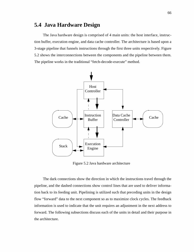
66
5.4 Java Hardware Design
The Java hardware design is comprised of 4 main units: the host interface, instruc-
tion buffer, execution engine, and data cache controller. The architecture is based upon a
3-stage pipeline that funnels instructions through the first three units respectively. Figure
5.2 shows the interconnections between the components and the pipeline between them.
The pipeline works in the traditional “fetch-decode-execute” method.
The dark connections show the direction in which the instructions travel through the
pipeline, and the dashed connections show control lines that are used to deliver informa-
tion back to its feeding unit. Pipelining is utilized such that preceding units in the design
flow “forward” data to the next component so as to maximize clock cycles. The feedback
information is used to indicate that the unit requires an adjustment in the next address to
forward. The following subsections discuss each of the units in detail and their purpose in
the architecture.
Figure 5.2 Java hardware architecture
Cache
Stack
Cache
HostController
ExecutionEngine
InstructionBuffer
Data CacheController

67
5.4.1 Host Controller
The Host Controller is the central point within the architecture for communication
with both the on-board memory and the host computer. It is involved in retrieving instruc-
tions and data as well as handshaking with the software partition in performing context
switches. Bytecodes are retrieved from memory and are pipelined to the Instruction
Buffer. Any request from the Instruction Buffer to change the address of fetching results
in a delay of execution. The Data Cache Controller only requests data when the current
instruction is waiting for the data, thus any requests from the Data Cache Controller for
data take precedence over the fetching of instructions. As such, a variable delay in pro-
cessing is possible due to the transaction requests of other components. This is necessary
since execution cannot continue until the higher precedence requests, which include data
accesses, and stack overflows/underflows are fulfilled.
5.4.2 Instruction Buffer
The Instruction Buffer acts as both an instruction cache and a decoder for instruc-
tions. The cache can be variable size, and is primarily determined by the amount of
design space that is available. A sufficiently large cache is preferable, as it provides a
higher probability that upon executing a branch instruction, the next instruction will
already be in the cache and not require a delay as the instruction is retrieved from on-
board memory. There is no real disadvantage to having a large cache, other than the area
required to support it. Since the target environment is an FPGA with a fixed area, using
the remaining area available is not costly. When the cache has room for more instructions,
or the instruction required by the Execution Engine is not located in the cache, then the
Instruction Buffer requests the next instruction from the Host Controller.
Instruction decoding is performed to align the instructions before passing to the
Execution Engine. The Java virtual machine has the property of having different sized
instructions, and the instructions come from software packed together to reduce memory
usage. In the current target environment the memory available on-board is rather low
(4Mb). Therefore, it is better for the co-design to perform the decoding and padding in
hardware rather than software in order to utilize the memory to the fullest and reduce
communication.

68
The Instruction Buffer decodes the instruction for the Execution Engine to execute
next and pipelines the instruction through. The Instruction Buffer does not have branch
prediction logic and as such simply feeds the next sequential instruction. In the event that
a branch occurs, the Execution Engine ignores the incorrect pipelined instruction and sig-
nals the Instruction Buffer for the correct execution location. When ready, the Instruction
Buffer pipelines the correct instruction. This may take a variable amount of time depend-
ing on cache hits and misses. In the event of a cache miss, the Instruction Cache is
cleared and it starts re-filling at the new branch address.
5.4.3 Execution Engine
The Execution Engine receives instructions from the Instruction Buffer and exe-
cutes the instruction. To assist in the execution, the Execution Engine has a hardware
stack cache of 64-entries that contains the top elements on the stack. As the stack under-
flows/overflows, stack elements are communicated with the Host Controller that manages
the complete stack in the RAM on the FPGA card. This on-demand loading and storing of
the stack prevents against unnecessary loading of the stack when context switching to
hardware, when execution may return back to software quickly. It is not seen as a perfor-
mance penalty when the stack elements are required and execution is stalled, since execu-
tion will have to be delayed in either situation. This approach protects against situations
where execution may return to software before the stack elements are required.
The Data Cache Controller is used to fetch/store data from/to the execution frames
local variables. Data that is required in the Execution Engine from the constant pool is
received directly through the Host Controller. This is done since the constant pool will
never be updated in the hardware design. Thus, instructions that require accessing the
constant pool or local variables take a performance hit. This is unavoidable due to the
potential size of both the constant pool and local variables. The Java virtual machine
avoids taking this hit by loading data onto the stack, performing its manipulations there,
and only pushing the data back out to memory when completed.

69
5.4.4 Data Cache Controller
The Data Cache Controller is responsible for interacting with the memory for both
loading and storing data from the local variables when required. Ideally it contains a
cache that buffers data to reduce the number of transactions with the on-board memory.
This cache is a “write through” architecture that writes cache data to the RAM immedi-
ately upon writing to the cache. This prevents the cache having to be flushed when execu-
tion returns to software. In the event that no design space is available to house the cache,
the size of the cache can be zero, which results in a memory transaction every time the
Execution Engine makes a request. The effects of this on performance are dependent
upon the difference in penalties for accessing the on-board RAM instead of the local
cache.
5.5 Design Characteristics
The architecture possesses various features that allow it to be a successful design in
the resource restricted target environment. The design is based on a native stack and a
pipelined architecture. It also attempts to be active and assists the software in the transfer
of data between software and hardware. This is achieved by the loading of the data stack
in hardware on demand. This avoids the situations where the data stack is loaded, only to
have execution switch back to software. This is an expensive penalty since the stack
needs to be stored back to memory shared with software. The Data Cache Controller is
designed to push any cached data element back to memory shared with software on writ-
ing the element to the data cache. This avoids dumping the entire cache to RAM when
context switching occurs.
The design is also compact and flexible as required. The Instruction Cache and
Data Cache are both configurable and can be resized to accommodate a larger or smaller
memory cache. As expected, the larger the cache the better up to an optimal size, but this
is a trade-off against area resources. The core pipeline can be altered to remove the data
cache from the design completely. This is possible; however removing the data cache
70
forces all local variable accesses to communicate with the external RAM memory. This
drastically affects performance as expected and should only be performed when the
FPGA resources are at a minimum.
The true power of this hardware design for the virtual machine is that it is generic.
It is capable of being used to represent a wide range of architecture paradigms provided it
is based on the fetch-decode-execute strategy. This encapsulates a wide range of architec-
tures, most notably both stack and register based. This will potentially allow the same
overall design to be used for many different virtual machine hardware designs. The inter-
nals of each component may be required to change to adapt, but the overall structure can
succeed.
5.5.1 Comparison to picoJava
The picoJava core is the original design of a Java processor based on the virtual
machine for the goal of creating a native Java computer [95-102,107,75,81]. Thus, a com-
parison of distinguishing features between the design of picoJava and that of the co-
design is appropriate. Through the comparison it is clear that both designs share various
basic characteristics. However, they also differ significantly.
A major difference between the picoJava core and this design is the environment for
which they are targeted. The picoJava core is designed for the purpose of being the sole
processing unit, while the approach described here is intended to complement an already
existing general microprocessor. Thus, the proposed architecture does not require operat-
ing system instructions for support in accessing hardware components such as RAM and
various busses, as well as additional instructions for supporting different languages and
paradigms. An example of this is the ncstore_word instruction, for performing a non-
cacheable store of an integer to memory [101].
With a greater restriction in the design space available, it was deemed suitable to
remove the process of folding instructions from hardware. This process can be relocated
to software. The restriction in design space results in less area and less space to imple-
ment special instructions that can perform multiple Java virtual machine instructions as a
single instruction. Any special techniques that can be utilized to increase performance

71
through folding, re-ordering, or re-structuring of instructions are left to be implemented
in software. This is beneficial not only for saving precious design space, but also for per-
forming the operation during class loading where it needs to take place once only. This is
as opposed to hardware where it is done at every encounter of the instructions.
The picoJava core provides flexibility in its design with the caches it uses and
allows for various cache sizes. This design also contains caches for the same purposes,
but it emphasizes flexibility with much smaller sizes. The picoJava specification outlines
the caches as ranging from 16Kb to 0Kb in size. This hardware design pushes the smaller
caches further, by using caches that are 1Kb to no cache. The smaller caches are attribut-
able to this hardware design only executing one given method at a time whereas the pico-
Java processor must support multitasking of multiple methods. Thus, a larger cache is
necessary.
Overall, the emphasis on the differences between the picoJava core and this design
is in the simplicity and reduction of the design space. This is a necessary step for the tar-
geted environment. This can be clearly seen in the simplified pipeline architecture in
comparison with the complex parallel architecture of picoJava with instruction folding.
The differences between the co-design approach and picoJava can also be seen in
the users and applications targeted by each. Both designs can be used for embedded sys-
tems, but the co-design could be better for this context due to its smaller size and tight
coupling with a microprocessor along with other factors. The picoJava design has extra
functionality that may be unnecessary in an embedded system.
5.6 Hardware Simulator Justification
When attempting to prototype a hardware design, the question arises as to whether
the design should be implemented in hardware, or simply simulated in software. There
are many advantages and disadvantages to each approach and each project needs to be
evaluated independently as to which is more appropriate. For this project it was decided
to simulate the hardware architecture. There are several reasons for this decision:
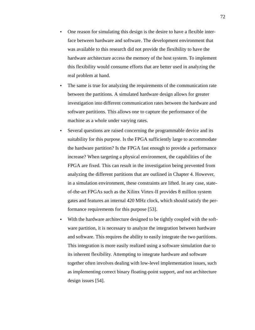
72
• One reason for simulating this design is the desire to have a flexible inter-
face between hardware and software. The development environment that
was available to this research did not provide the flexibility to have the
hardware architecture access the memory of the host system. To implement
this flexibility would consume efforts that are better used in analyzing the
real problem at hand.
• The same is true for analyzing the requirements of the communication rate
between the partitions. A simulated hardware design allows for greater
investigation into different communication rates between the hardware and
software partitions. This allows one to capture the performance of the
machine as a whole under varying rates.
• Several questions are raised concerning the programmable device and its
suitability for this purpose. Is the FPGA sufficiently large to accommodate
the hardware partition? Is the FPGA fast enough to provide a performance
increase? When targeting a physical environment, the capabilities of the
FPGA are fixed. This can result in the investigation being prevented from
analyzing the different partitions that are outlined in Chapter 4. However,
in a simulation environment, these constraints are lifted. In any case, state-
of-the-art FPGAs such as the Xilinx Virtex-II provides 8 million system
gates and features an internal 420 MHz clock, which should satisfy the per-
formance requirements for this purpose [53].
• With the hardware architecture designed to be tightly coupled with the soft-
ware partition, it is necessary to analyze the integration between hardware
and software. This requires the ability to easily integrate the two partitions.
This integration is more easily realized using a software simulation due to
its inherent flexibility. Attempting to integrate hardware and software
together often involves dealing with low-level implementation issues, such
as implementing correct binary floating-point support, and not architecture
design issues [54].

73
• Targeting a specific platform environment such as the one from Virtual
Computer Corporation introduces further complexities into the process.
Technical issues can emerge that affect the overall process and hinder anal-
ysis. For example, the above mentioned development environment con-
tains technical issues with the provided interface and prevents the hardware
partition from signalling the software partition. Technical issues such as
these are not the focus of the work and in a physical environment can result
in loss of time or project failure.
Additionally, there are the normal benefits of simulating over implementing that include
the following:
• Lower costs, as simulating requires no special hardware.
• Better software support, as support in software is more dynamic and exten-
sive than in hardware.
• Fewer environment quirks. Software allows a generic environment, where
a hardware implementation requires the design to involve its quirks.
• Faster development time, as typically software development is faster than
hardware implementation.
Overall, this flexibility allows for design space exploration which is crucial to this
research process.
Various simulation environments already exist for simulating hardware designs.
Unfortunately, there are two major factors that suggested using a custom simulator. The
first is the complexity of the software component. The software component in this co-
designed system is very intricate and relies upon certain functionalities available through
the host operating system, namely scheduling and memory management. Running the co-
designed software in an encapsulated simulator would not provide realistic results. Sec-
ondly, the tight integration between the software and hardware components requires the
intricate integration of the software components with the hardware simulator. With the

74
low level dependency between the hardware and software partitions, it is unclear if the
available simulators would support and allow investigation of this communication. For
these reasons, it was decided to build a custom simulator in software.
The next section will discuss some of the techniques that were used in simulating
the hardware design to ensure accuracy and hardware portability in simulation.
5.7 Software Simulator
This section discusses various techniques used to implement the software simulator
of this hardware design. Each of these techniques is a step towards not only achieving a
correct simulation timing at the clock level, but as well to help the later implementation
become an easier task. At the end of this exercise it is anticipated that specification of the
design for synthesis can progress from the specification used in the simulator.
5.7.1 Simulator Goals
Overall, the simulator’s purpose is to give an indication of the potential perfor-
mance of the hardware design described in section 5.4. There are many different reasons
for simulation, but this simulator is intended to give an indication of the possible perfor-
mance so an assessment can be made of the feasibility in using a co-designed virtual
machine. To accomplish this there are several smaller goals that the simulator must strive
to achieve to provide an accurate indication. For this simulation these goals are:
• To model the pipeline stages of fetching, decoding, and executing Java
bytecodes in parallel.
• To model the various data caches that exist in the design and provide flexi-
bility for investigation into the effects of varying sizes.
• To model the communication interface between the hardware design
(FPGA) and the software partition (host processor) through the PCI inter-
face.
• To model the memory available to the hardware design (FPGA) through
the VCC (Virtual Computer Corporation) custom interface [110].

75
• To model the interface between the hardware design and the memory sub-
system that is available on the host workstation.
• To model the different execution stages of each instruction that is sup-
ported by the hardware design.
• To provide a reasonably fast simulation of the hardware design.
• To provide an accurate simulation of the hardware design.
To best achieve these goals, it is suitable for the simulator to leverage known char-
acteristics of existing hardware components. Likewise, it is desirable for the simulator to
be based upon a specification language that is synthesizable into a hardware implementa-
tion. The next section describes different assumptions that the simulator used to provide
an accurate measurement of execution time.
5.7.2 Simulator Design Overview
The most critical decision to be made in the simulation is the specification lan-
guage to use in describing the hardware design. For this it was decided to use the C pro-
gramming language. Primarily this decision is based on the implementation language of
the software partition, and C also allows easy integration with software. Having the simu-
lator easily integrate with the software partition allows the research to examine full appli-
cations and the interactions between the partitions during execution. Additionally, the C
language provides similar programming constructs to VHDL, a common specification
language for hardware, and support for low-level bit operations. It is also beneficial that it
is a language that can generate fast binaries in comparison to other languages. This leads
to a fast simulation environment that can be used to examine full applications. C also pro-
vides support that can be used for exploration without requiring vast amounts of develop-
ment time. An example of this is support for floating-point operations.
It was decided to base the simulation on the VHDL behavioral model [7,37]. Using
the VHDL model is a justifiable decision since the support for the development environ-
ment described in subsection 5.2.1 is provided in VHDL. Limiting the usage of C in the
implementation to only the subset of constructs that are supported by VHDL can contrib-
ute towards a later effort of converting the specification to VHDL if deemed desirable.

76
Some additional effort is necessary to provide support for VHDL constructs that are not
directly available in C, a discussion of some of these issues are addressed later in the dis-
sertation.
The simulator performs a time-driven simulation of the hardware design for the
Java virtual machine. In this simulation, each of the different components in the design
executes for one clock cycle and then interchanges signals that relay information between
the components. Each of the different components in the hardware design is either imple-
mented as a custom defined component, or modelled using some other existing compo-
nents that are available within the development environment described in subsection
5.2.1. The following Figure 5.3 depicts the components that are modeled by the simula-
tor. Components that are shaded in the diagram are modeled after existing components
that exist within the development environment presented at the beginning of the chapter.
The remaining components are custom defined for the simulator’s purpose.
Figure 5.3 Java hardware architecture’s simulated components.
Cache
Stack
Cache
HostController
ExecutionEngine
InstructionBuffer
Data CacheController
PCI Interface

77
5.7.3 Simulator Implementation Details
In order to implement the simulator, several implementation techniques were used
to adapt the implementation language of the simulator, C, into the modeling language
used to describe the simulator, VHDL. This section describes these and some other details
involved in implementing the simulator.
5.7.3.1 Signal Propagation
Using the VHDL behavioral model, it is possible to specify each of the different
components in the hardware design as its own process. To provide an accurate simulation
of the process concept within the VHDL language, the simulator is implemented using a
distinct function to encapsulate the description of each hardware process (or component).
To support the VHDL specification model further, signals between hardware components
are implemented using two global shared variables. One variable possesses the state of
the signal at the current time t, and the second variable holds the value of the signal at
time t+1. Using this technique, the setting of signals can be delayed until each of the
components has executed for the equivalent of one hardware cycle. Thus signal assign-
ments are delayed and propagated at the appropriate time. This results is the main loop of
hardware simulation depicted in Figure 5.4. Arguably, threads could have been used to
provide the effect of each component being its own execution thread, however this would
have affected the thread management necessary for Java support.
With this technique, it is also possible to verify the correct propagation of signals
between components by changing the order in which components are executed. Since the
Figure 5.4 Hardware simulator main loop of execution.
while (executing){ hardware_component_1(); hardware_component_2(); ... hardware_component_n(); propagate_signals();}

78
signals are not propagated until after all of the components have executed for one clock
cycle, the order of component execution does not matter. This validation technique has
been used with the simulator to verify that connections between components are correct
and signals are propagated correctly.
5.7.3.2 PCI Interface Model
To ensure a correct and realistic simulation, the interface to the hardware design is
wrapped by the interface definition as provided in part by the development environment
described in subsection 5.2.1 [110,112,114]. This interface in turn wraps the Xilinx PCI
interface as provided from Xilinx [53].
In simulation, a wrapper is used to provide the same interface to all external
resources. This wrapper provides and ensures not just the same signals, but also the same
properties. External RAM that is located on the FPGA card is accessed through this inter-
face. So too is the interrupt signal to software to indicate the hardware has completed
some assigned task. To complete the simulation, the interface wrapper also incorporates
all of the appropriate delays associated with the signals. The most notable of these delays
is the time required to access the RAM memory on the FPGA card. This delay is a 2
cycle read and a 3 cycle write.
This is one area, among many, that benefited from simulation. This interface could
now be more easily enhanced and extended. Initially, the interface contained only a host
to FPGA communication direction flow, with communication in the other direction being
performed by writing to the on-board RAM and signaling the software. Now the idea of
having communication in the reverse direction could be tested. Simulations could be eas-
ily performed to determine the threshold communication rate between hardware and soft-
ware, and the benefits of using a faster connection.
The interface for supporting interactions with the host systems memory is extended
to contain the same interface characteristics used to access the external RAM located on
the FPGA card. This interface consists of an address bus (32 bits wide), a data bus to
deliver the data to and from the memory (32 bits wide), and three bit signals to indicate
the desired operation, read or write. The three signals replicate the same control signals

79
used by the interface to manipulate the external memory on the FPGA card. The use of
the same three signal specification is for consistency.
For the delay in accessing the memory, it was decided to allow the simulation to be
configured for a fixed delay by the user. A variable delay is also possible, by introducing
a random function into the macro definition of delay in the implementation. This delay
can be used to simulate the effects of operating over different communication connec-
tions. This delay is on top of the 2-cycle read and 3-cycle write delay needed for setting
the signals to memory properly. For the purpose of this research, the delay was set to be 0
clock cycles. This was done to provide equivalent timing delays as experienced by
accessing external RAM on the FPGA card, and also to obtain the optimum performance
measurement. In the later analysis of the fully integrated co-designed virtual machine, the
speed of this communication connection is examined and factored into the performance
summary.
5.7.3.3 Modeling Memory Caches
Within the hardware design there are several data caches. To implement these
caches it was decided to use existing support for memories found in the Xilinx Founda-
tion environment. Using this feature of the development environment required modeling
the memories interface and timing characteristics according to the specification provided
by Xilinx. For these caches, the Xilinx LogiBlox tool specifies the interface in Figure 5.5.
In the diagram, dashed lines represent bus signals that are wide enough to encode an
address. This is dependent on the length of the memory, that is configurable through a
global macro definition in the simulator. Thus allowing an investigation into the effects of
using different length caches. Solid thick lines represent bus signals that carry the data
into and from the memory. In the hardware design, these signals are 32 bits wide. Lastly,
the solid thin line is a single bit input to indicate whether the desired operation is to read
or write. This interface works with a 1-cycle read and a 3-cycle write. It can be seen that
the memory block provides support for both reading and writing simultaneously.
To ensure a correct simulation, the memory caches are not referred to directly in the
simulation, but rather through the various signals that comprise the interface. Having the
memory accessed through the interface ensures a correct simulation in this perspective.

80
At a later time when the design is fully implemented in hardware, this will ease the transi-
tion from simulation to implementation.
5.7.3.4 Primitives Enforcement
The final practice is to use only basic operations and data manipulations that are
supported by the VHDL model. All of the constructs used in the C implementation are
directly transferable into constructs of the VHDL language. There is no formal checking
to ensure that this is upheld in the simulator's implementation. This can be avoided, how-
ever, by using sound software engineering practices, code review, and using interfaces to
other components correctly. Proper use of the interfaces for the PCI interface and memory
often exposed timing idiosyncrasies between components and violations of primitive
operations.
What is uncertain is the number of clock cycles required to perform some of the
operations involved in the instructions themselves. Depending on the implementation
techniques used by the designer, these instructions can require a different number of clock
cycles. For example, a designer could choose to have a double precision multiplication
instruction occur in as little as 1 cycle, or as many as 10 for instance. The trade off how-
ever is that the overall clock rate of the design is affected. In this case, the implementa-
tion that performs the operation in 10 cycles could execute at a clock rate 10 times higher
than the other implementation.
In these instances a delay can be incorporated into the simulator to acquire the cor-
DP Out
Data OutAddress
DP Address
Data in
read/write
Figure 5.5 Block diagram of memories available through the Xilinx Foundation

81
rect timing requirements. It was decided that no delay would be added and operations
would take a base of 1 clock cycle to complete beyond the number of clock cycles neces-
sary to interact with the caches in fetching operands and storing results. This decision is
justifiable since it makes no assumptions about the technology or other components used
(such as a floating-point unit). From the base time acquired through simulation, the analy-
sis can factor in additional time required for completion of operations once the full target
technology and components are known. This is also suitable since different clock rates
need to be considered for other factors.
5.7.3.5 Simulator Initialization
With the transfer of execution from software to hardware, there is a need to transfer
appropriate information that is needed in starting the hardware execution with the correct
state of the virtual machine. This involves transfer of such data entities as the program
counter, stack pointer, stack base pointer, local variable pointer, and constant pool refer-
ence. These are in addition to any data transferred for caching in a local memory system
available to the hardware design. Likewise, this information needs to be transferred back
to software upon a context switch to software.
The necessary time to perform the transfer of data, both the reference values and
any data to cache, are dependent on the communication link between the hardware and
software partitions. As such, the time necessary to perform these operations are not fac-
tored into the simulator’s time results, but instead are left to be included as part of the
communication timing. This allows the simulator to be used flexibly with different con-
figurations of communication resources.
5.7.4 Simulator Validation
To validate the simulator for correct execution, the result of execution through sim-
ulation was compared against the expected result of execution gathered from software
execution. This is made possible since an already validated software implementation
exists and is available. With any given execution in the hardware partition, the results are
stored into the stack, local variables, and constant pool. Through duplicating these mem-
ory regions, it is possible to perform duplicate execution of a given block of bytecode.

82
Comparisons can then be performed with the different memory regions of execution to
confirm that both regions produce identical results. This technique was used with all of
the benchmark tests described in the dissertation and for all configurations at each transi-
tion from hardware to software execution.
Other pre-cautionary measures can also contribute to the validation process. One
example is to clear all interconnection signals between components to contain default val-
ues. This can be used to ensure communication between components is timed correctly
and only happens through the proper supported interface. From this a very high level of
confidence is attained that the simulator executes the bytecode correctly. Likewise, the
execution order of the hardware processes being simulated can be interchanged. Doing so
ensures that no illegal interconnects or assumed ordering is being used.
To confirm that the simulator produces correct timing results based on the design of
the hardware partition, an automated task is not possible. Instead a manual inspection of
the simulator during execution is necessary. While this remains a time consuming task, it
is made easily possible through the support readily available in a software environment.
Through the use of focused test cases and print statements, it can be confirmed that the
simulator is conforming to the hardware design and producing correct timing results.
5.7.5 Execution Time Measurements
A basis must be formed for the comparison of execution time between the hard-
ware and software partitions. The simulator as previously described in section 5.6.1 is
capable of providing a measurement of the number of clock cycles required to execute a
given task. It is not possible however for the simulator to provide any insight into the pos-
sible clock rate that the design can perform using any of the existing FPGA technologies
available.
A timing approach using clock cycles is also possible with software execution due
to the capability of Intel, and compatible, processors to allow a software application to
determine the number of clock cycles required to execute a software region [56]. In this
case however, the processor clock rate is known.
Any comparison involving execution times generated through use of the simulator

83
must be done at the clock cycle level. Even then, care must be exercised to consider the
different possible clock rates that the design could attain. For this, the results should con-
sider different possible ratios of clock rates between the software execution and the hard-
ware simulator. This is a suitable technique since it can also be used to factor in not just
the difference in clock rates because of what the hardware design is capable, but also can
be used to consider the difference in clock rates deliverable by the underlying reconfig-
urable device.
For example, using the development environment described earlier in subsection
5.2.1, the FPGA available delivers a maximum clock rate of 100 Mhz, while the desktop
workstation it is connected to contains an Intel processor with a 750 Mhz clock. Even in
the event that the hardware design can provide a clock rate above 100 Mhz, it is still con-
strained by the clock rate of the physical FPGA. This execution timing technique allows a
direct analysis from the data available and factors in both the clock rate of the hardware
design and that of the physical device it is implemented upon.
For the remainder of this dissertation, the discussion will only consider one differ-
ence between clock rates. This difference is used for simplicity and will represent both of
the factors that can contribute to different clock rates between the software and hardware
partitions.
5.8 Results
Before integration of the hardware architecture with the software partition, the
design must be tested for both correctness and performance against the software virtual
machine. This fine-grain testing allows for insight into the potential gains a co-designed
virtual machine can provide. For this, the tests may only use the subset of Java bytecode
that is available currently in the hardware partition. The following tests were designed
and executed:
• a loop counter,
• Fibonacci finder,
• Ackerman function,

84
• bubble sort, and
• insertion sort.
Each of these tests are designed to evaluate various design features of the hardware
architecture. The first two tests allow for a long duration and constant test with no effects
of stack cache, data cache or instruction buffer interference. The Ackerman function tests
the architecture for handling of overflow/underflow of the stack cache. The bubble sort
test sorts local variables and rigorously tests both the instruction cache and the data
cache. The insertion sort test utilizes the ability of the hardware architecture to access the
host systems memory.
For gathering test results, the software execution was performed on a Windows
2000 workstation (with Intel pentium III 750 MHz processor) running the Sun Microsys-
tems SJDK v1.3.0_02 Java virtual machine, with no other user applications executing.
Thus, it is not guaranteed that the software timings are not affected by contention with
other system processes over the processor. However, this contention is at a minimum in a
typical workstation environment. Results of execution timings are in clock cycles, and the
difference in processor speeds is not considered in the comparison.
5.8.1 Linear Execution Tests
These tests are designed to show the potential improvement of the hardware execu-
tion over software interpretation. Figure 5.6 shows the ratio of increase of the simulated
hardware over the timed software execution. It can be seen that the software performance
improves as the problem becomes larger. This is attributed to the effects of software exe-
cuting in a multi-tasking environment, where a penalty is observed for starting the soft-
ware process. As the performance is extended over a larger period, these effects are
minimized to give clearer results. At the largest problem size computed, the hardware
design provides performance gains at a factor of 11.7 for the simple loop counter and 8.7
for the Fibonacci problem.
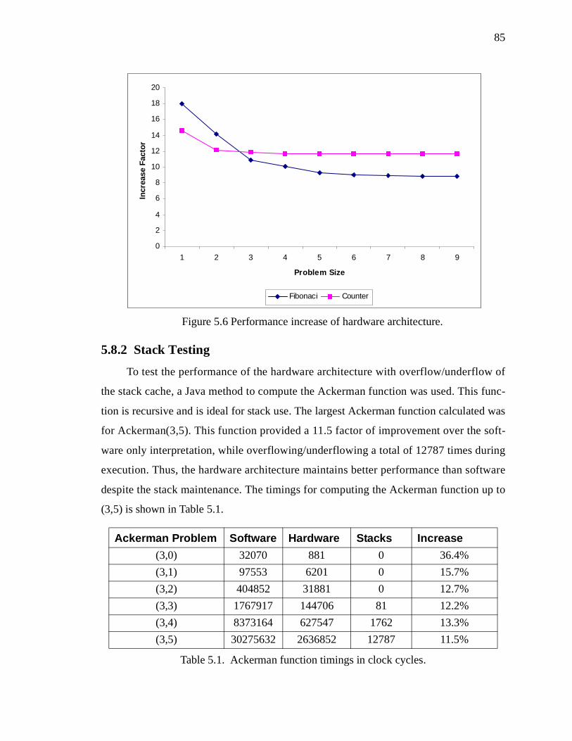
85
5.8.2 Stack Testing
To test the performance of the hardware architecture with overflow/underflow of
the stack cache, a Java method to compute the Ackerman function was used. This func-
tion is recursive and is ideal for stack use. The largest Ackerman function calculated was
for Ackerman(3,5). This function provided a 11.5 factor of improvement over the soft-
ware only interpretation, while overflowing/underflowing a total of 12787 times during
execution. Thus, the hardware architecture maintains better performance than software
despite the stack maintenance. The timings for computing the Ackerman function up to
(3,5) is shown in Table 5.1.
Ackerman Problem Software Hardware Stacks Increase
(3,0) 32070 881 0 36.4%
(3,1) 97553 6201 0 15.7%
(3,2) 404852 31881 0 12.7%
(3,3) 1767917 144706 81 12.2%
(3,4) 8373164 627547 1762 13.3%
(3,5) 30275632 2636852 12787 11.5%
Table 5.1. Ackerman function timings in clock cycles.
0
2
4
6
8
10
12
14
16
18
20
1 2 3 4 5 6 7 8 9
Problem Size
Incr
ease
Fac
tor
Fibonaci Counter
Figure 5.6 Performance increase of hardware architecture.
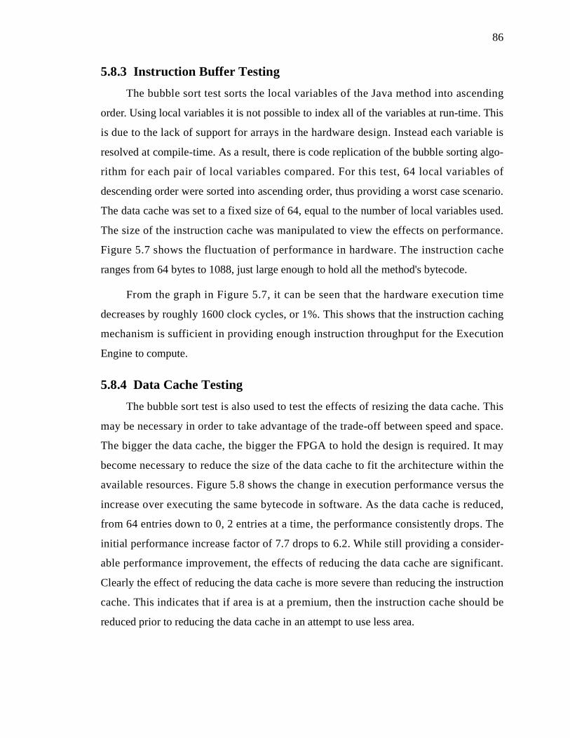
86
5.8.3 Instruction Buffer Testing
The bubble sort test sorts the local variables of the Java method into ascending
order. Using local variables it is not possible to index all of the variables at run-time. This
is due to the lack of support for arrays in the hardware design. Instead each variable is
resolved at compile-time. As a result, there is code replication of the bubble sorting algo-
rithm for each pair of local variables compared. For this test, 64 local variables of
descending order were sorted into ascending order, thus providing a worst case scenario.
The data cache was set to a fixed size of 64, equal to the number of local variables used.
The size of the instruction cache was manipulated to view the effects on performance.
Figure 5.7 shows the fluctuation of performance in hardware. The instruction cache
ranges from 64 bytes to 1088, just large enough to hold all the method's bytecode.
From the graph in Figure 5.7, it can be seen that the hardware execution time
decreases by roughly 1600 clock cycles, or 1%. This shows that the instruction caching
mechanism is sufficient in providing enough instruction throughput for the Execution
Engine to compute.
5.8.4 Data Cache Testing
The bubble sort test is also used to test the effects of resizing the data cache. This
may be necessary in order to take advantage of the trade-off between speed and space.
The bigger the data cache, the bigger the FPGA to hold the design is required. It may
become necessary to reduce the size of the data cache to fit the architecture within the
available resources. Figure 5.8 shows the change in execution performance versus the
increase over executing the same bytecode in software. As the data cache is reduced,
from 64 entries down to 0, 2 entries at a time, the performance consistently drops. The
initial performance increase factor of 7.7 drops to 6.2. While still providing a consider-
able performance improvement, the effects of reducing the data cache are significant.
Clearly the effect of reducing the data cache is more severe than reducing the instruction
cache. This indicates that if area is at a premium, then the instruction cache should be
reduced prior to reducing the data cache in an attempt to use less area.
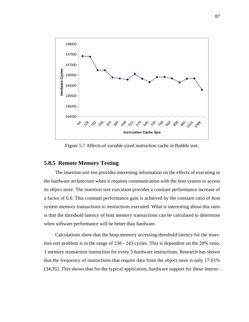
87
5.8.5 Remote Memory Testing
The insertion sort test provides interesting information on the effects of executing in
the hardware architecture when it requires communication with the host system to access
its object store. The insertion sort execution provides a constant performance increase of
a factor of 6.6. This constant performance gain is achieved by the constant ratio of host
system memory transactions to instructions executed. What is interesting about this ratio
is that the threshold latency of host memory transactions can be calculated to determine
when software performance will be better than hardware.
Calculations show that the heap memory accessing threshold latency for the inser-
tion sort problem is in the range of 238 - 243 cycles. This is dependent on the 20% ratio,
1 memory transaction instruction for every 5 hardware instructions. Research has shown
that the frequency of instructions that require data from the object store is only 17.61%
[34,35]. This shows that for the typical application, hardware support for these instruc-
144500
145000
145500
146000
146500
147000
147500
148000
64 128
192
256
320
384
448
512
576
640
704
768
832
896
960
1024
1088
Instruction Cache Size
Har
dw
are
Cyc
les
Figure 5.7 Affects of variable sized instruction cache in Bubble sort.

88
tions can provide a performance increase. These results can also be used to gain an
insight into the communication requirements between the hardware and software compo-
nents.
5.8.6 Results Analysis
For the tests above, the lowest performance increase ranged from factors of 6.2 to a
high of 11.7. Table 5.2 contains the lowest factors of improvement for each of the tests
without consideration for the differences in clock rates between the hardware and soft-
ware processing units. This provides an insight into the combined necessary support of
the reconfigurable device and the capable clock rate of the hardware design to provide a
performance improvement. Currently, general purpose processor technologies (such as
0
1
2
3
4
5
6
7
8
9
64 60 56 52 48 44 40 36 32 28 24 20 16 12 8 4 0
Data Cache Size
Per
form
ance
Incr
ease
Figure 5.8 Performance degradation for reduced data cache size in Bubble sort.

89
Intel) provide a clock rate that is 3 to 5 times faster than FPGA technologies. While this is
no indication that the hardware design is capable of these speeds, it does show current
FPGA technologies provide sufficient support.
5.9 Summary
This chapter discussed the design of the hardware partition for a co-designed vir-
tual machine. The co-design approach takes into consideration the target environment and
provides flexibility for implementation under different resource constraints. These con-
siderations include reduced area for design of the processor and memory areas, and for
slow communication rates between the physical components. A simulation technique is
presented and used to simulate the hardware design for the example Java virtual machine.
Using the simulation technique it is possible to explore the attainable performance
under different hardware restrictions. The results obtained show performance gains of up
to a factor of 11.7 between a hardware subset of the Java virtual machine and the same
subset from the Sun JDK virtual machine. It also demonstrates that if area for the design
is at a premium, reductions to the hardware design do not severely affect the perfor-
mance. With the different levels of performance factors attained, the relationship between
clock rates of the software and hardware designs was discussed. The results also pro-
vided some indication of the required communication rate between the hardware design
and the host system.
Performance Tests Minimal Performance Increase
Loop Counter 11.7
Fibonacci Finder 8.7
Ackerman Function 11.5
Bubble Sort 6.2
Insertion Sort 6.6
Average 8.94
Table 5.2. Minimal performance increase factors for each of the benchmarks based on cycle counts without consideration for clock rates.

CHAPTER 6
Software Design Chapter 6
6.1 Introduction
This chapter looks at the software design of the co-designed virtual machine. A sig-
nificant aspect of this design is the interface between the hardware and software compo-
nents. This is arguably the most important aspect of the co-design process. Without a
suitable interface between hardware and software, the co-design can fail providing a solu-
tion that meets the requirements. Dependent upon the development environment and
architecture chosen, there are some key factors that affect the interface. First, the architec-
ture provides two distinct processing units for execution, allowing a choice of which ele-
ment to use to execute a given program segment. Secondly, each processing unit has a
distinct memory system, and data must be transferred between each for execution control
to migrate. This chapter will examine the data that is exchanged and the choice of when
to migrate execution from software to hardware execution.
6.2 Software Design
As outlined in the partitioning chapter, the software partition exists to provide
resources and complete tasks on behalf of the hardware partition when needed. To facili-
tate communication between the two partitions, the communication is centralized on both
sides to a single control point. The hardware design contains a component called the Host
Controller which handles all incoming and outgoing communication. This includes direct
communication with the software partition and any communication with local or shared
resources such as memory. The software design contains a Hardware Handler interface
that software uses to communicate with the hardware partition. Figure 6.1 shows the
overview of how the hardware and software are connected and the components that pro-
vide an interface to each partition.

91
The Hardware Handler is the only software architecture difference in the software
design when compared to a fully software virtual machine. Figure 6.2 shows how the
Hardware Handler fits within the software architecture of the Java virtual machine. The
component has access to both the Instance and Object Stores to access data on behalf of
the hardware design. It also communicates with both the Scheduler and the Thread Pool.
This link allows the Scheduler to pass a Java thread for execution in hardware. Once exe-
cution in hardware is completed, the thread is returned to the ready queue in the Thread
Pool. The importance of this design is that the Hardware Handler is the central point of
communication with the hardware partition. This allows for easy control over the thread
that is executing in hardware. Figure 6.3 shows an overview of the interface between the
hardware and software partitions in the Java virtual machine.
With the small change to the software design, it is straightforward to reuse a lot of
the software architecture from a software only solution. This is an added bonus to speed
up the implementation process. In the example Java virtual machine, this allows reuse of
a significant portion of the implementation. All high-level scheduling, garbage collec-
tion, class loading, and API support can be reused.
HardwareSoftware
FPGA
HostController
HardwareHandler
Bus
Figure 6.1 Overview of interface design between hardware and software.
CPU

92
6.2.1 Data Objects Communication
Between the hardware and software division, there is a need to transfer certain data
elements with each execution migration. The data essentially captures the state of the exe-
cution at that instance. This state typically consists of a program counter indicating the
current execution location, any temporary set of data registers that hold intermediate val-
ues during execution, as well as any local variables for the execution frame. Exactly
Clock
Idler
Scheduler
Garbage Collector
Finalizer
ThreadPool
InstanceStore
ObjectStore
Hardware Handler
PCIBUS
Figure 6.2 Software partition design of Java co-processor.
Garbage Collector
Idler
Clock
Scheduler
Finalizer
Java HardwareHost System
Execution Engine
HostController
HardwareHandler
PCI Bus
Figure 6.3 Overview of Java interface design between hardware and software.
Data Cache Controller
Instruction Buffer

93
which data objects and how much bandwidth they consume is dependent on the particu-
lar virtual machine to be implemented and the hardware architecture. Independent of the
virtual machine, there is commonly a program counter and temporary data registers. For
the example Java virtual machine, this data includes:
• The program counter.
• The stack pointer.
• The local variable store pointer.
• The constant pool pointer.
With the development environment having distinct memory regions for the host
processor and the FPGA, the transferring of pointers is insufficient. The memory regions
themselves must also be transferred:
• Method block which contains the Java bytecode to execute.
• Execution stack that is used for holding temporary values during execution.
• Local variable store containing data values used within the method.
• Constant pool containing constants within the current execution state.
Several measurements were taken to determine the actual cost of communication
between the host and the co-processor connected through the PCI bus. Context switches
will vary in cost depending on the amount of data that must be transferred which is
dependent upon the current execution state. The targeted development environment, the
HOT-IIXL board, contains 4Mb of user memory. Both extremes of data transfer were
tested for performance [110]. For 100 transfers of zero data, i.e. a simple handshake, 4022
cycles were required. For 100 context switches with transfers of 4Mb data in each direc-
tion, 71926957 cycles were needed. Tests were performed on a 750Mhz Pentium III host,
which provides 1193180 cycles/second of computation. This clearly shows the high cost
in performing a context switch, especially when a high data transfer is required. The next
section examines the case when the data must be transferred between two different mem-
ory systems, and how this can be done efficiently.

94
6.2.2 Communication Techniques
Each region possesses various traits that can be exploited to reduce the traffic
between the memory systems. This can be done through three simple checks on the data
that needs to be communicated. First, is the data capable of being changed in the two par-
titions? If not, then the data can be disregarded on the returning transfer. Secondly, is the
size of the data dynamic? If so, then it is possible that the transfer can be reduced by
sending only the current valid data. Finally, if the data is a substantial size and is infre-
quently changed by the hardware partition, it may become more fruitful to use flags to
indicate when the data has been changed and needs to be transferred.
Each of these aspects is dependent on the data characteristics within a specific vir-
tual machine. For the example Java virtual machine, the method block contains data that
is only changed by the software host. Examining the instructions in each partition, it is
clear that this is the case. These get changed when a new method is called, a complex
instruction is resolved and replaced by its quick variant, or a constant pool value is
resolved. This results in a one-way transfer of the data being necessary. Thus, the com-
munication can be simplified, at least in one direction. The execution stack and local vari-
ables are manipulated in hardware, so data is required to be copied back to software. The
execution stack, however, is known to dynamically change size during execution. With
the necessary exchange of the references for both the top and bottom of the stack, it is
beneficial to transfer only the data within this range that is known to be still valid.
Through these techniques, it can be seen in Figure 6.4 that the communication transfer
between the two partitions is substantially reduced. Overall, the average transfer rate
drops to under 14% of the original data transferred when going from the software to hard-
ware partition.

95
6.3 Context Switching
With the addition of a second processing unit, there is the burden of determining if
and when the execution should be moved from one unit to the other. In a traditional hard-
ware/software co-designed system, both partitions are disjoint in their capabilities
because of factors such as cost and design space. However, as previously mentioned in
section 4.2, no significant penalty exists for having the software partition also contain the
functionality of the hardware partition. This decision results in the ability to choose when
to context switch between the two partitions.
Since the architecture has two distinct memory systems for each processing unit, the
cost of a context switch from one unit to another is high due to the penalty in transferring
the necessary data between memory subsystems. With this high cost, it is desirable to per-
form a context switch only in instances where the performance gain of making the transi-
tion will result in a significant gain that outweighs the cost of the context switch. The
next section discusses several algorithms that were used to perform a dynamic run-time
0
100
200
300
400
500
600
Bytes
com
pres
s db
man
del
quee
n
raytr
ace
SW -> HW HW -> SW
Figure 6.4 Average communication bandwidth used in context switching.

96
analysis of the Java bytecode to mark appropriate locations where performing a context
switch is worthwhile [60]. These algorithms are dynamic as they select segments of byte-
code that are large enough to execute in the hardware partition as to outweigh any costs
incurred from performing the context switch. Not only do they select the bytecode
dynamically at run-time, but the algorithms are also dynamic in accepting the penalty for
context switching when execution begins. Currently, this analysis needs to be done at run-
time since any changes made to the bytecode at compile time will result in loss of porta-
bility. If the augmenting of the bytecode were to take place at compile time, a more in-
depth analysis could take place and a resulting better algorithm could be used. This would
completely eliminate the performance hit at run-time.
There are three basic algorithms that were developed and investigated: pessimistic,
optimistic, and pushy. Each of these algorithms analyze the methods found within each of
the classes that are requested for loading during the execution of a given Java program.
The algorithms insert new opcodes into the methods that result in a context switch from
one processing unit to another. Execution will switch from one unit to another when
encountering one of these instructions, or when an instruction in hardware is encountered
that can only be executed in software. With the addition of bytecodes into the methods,
the class structure itself is changed to reflect this and make the class legal for classload-
ing. Each of the algorithms work on the basic idea of creating blocks of bytecodes that
can be executed within the hardware partition. The analysis to create the blocks is done
assuming the bytecodes will be executed sequentially and branch statements fail causing
execution to continue sequentially. A better analysis is more than likely possible by inves-
tigating the branching structure of the bytecode, however such an analysis is too costly to
perform at run-time, especially with no predictive branching model for the application.
Each of the algorithms has the same complexity and requires one and a half passes over
the bytecode.
In analyzing the algorithms, not only do the algorithms need to be compared, but
also the optimal block size must be considered. If the minimum block size is chosen
(size=1), then a context switch to hardware will occur for every instruction that can be
executed in the co-processor. In essence, this will show the performance of the co-

97
designed virtual machine where there is no overlap between the hardware and software
partitions. This will result in many instances of context switching to execute one instruc-
tion. Clearly, this will result in slower performance if one connects through a slow PCI
bus. If a ridiculously high block size is chosen, then very few, if any, hardware blocks
will be found and all execution will take place in software. This is complicated by the fact
that branching instructions within a block can result in effectively shortening or lengthen-
ing the block. Thus finding a block size, in addition to an algorithm, to minimize context
switching yet maximize hardware execution is critical. The performance of a given algo-
rithm will be application dependent, but this research aims for an algorithm that is suit-
able for most applications.
The following subsections discuss the various algorithms that were investigated.
For simplicity in the discussion, the portion of the virtual machine implemented on the
FPGA will be referred to as the hardware side/unit.
6.3.1 Pessimistic Algorithm
The first approach taken to blocking code for execution in the hardware unit is to
assume the worst case scenario. This approach only inserts instructions to context switch
to hardware in the event that the next predefined number of sequential instructions it sees
are to be executed in hardware. Context switching back to the software partition occurs
when an instruction not supported in hardware is encountered. Any instructions that are
initially software instructions, before being changed into the hardware quick versions, are
considered to be software-only instructions during the code augmenting. This ensures that
if no branching takes place in the block of instructions, then the minimum number of
instructions will be executed to offset the cost of performing the context switch.
The resulting drawback of this approach is that the execution becomes more soft-
ware bound than hardware bound. This is due to two different characteristics of the byte-
code. First, that there are a minimal number of blocks of sequential instructions made up
of these types of instructions. The frequency of code sections that are composed of solely
hardware instructions is low. As a result there are few context switch instructions added
into the methods and execution tends to stay within the software partition. The second
characteristic is that blocks of bytecode that contain instructions that will later be trans-

98
formed into their quick equivalent, that can be executed in the hardware unit, will never
be tagged to be executed in hardware. Once transformed, if the instruction is encountered
while executing in hardware, it will be executed there, but the algorithm fails to push the
execution to hardware if the instruction is encountered in software. This occurs since the
algorithm does not consider the changing of instructions by the virtual machine during
execution.
6.3.2 Optimistic Algorithm
The optimistic approach attempts to capture the instances of sequential bytecodes
where some of the instructions are initially software instructions, but will later be trans-
formed into hardware instructions. This is accomplished by assuming that this class of
instructions is executable in hardware during the augmenting process. It is done with the
desire of creating more blocks of instructions, which can be executed in the hardware par-
tition, thus resulting in more context switch instructions. As with the pessimistic
approach, execution stays in the hardware partition until an instruction is encountered that
requires execution in the software partition. To eliminate useless context switching where
a context switch to hardware instruction is immediately followed by a software instruc-
tion, a check is made before every context switch to ensure that the next instruction is
truly executable in hardware.
The resulting drawback of this approach is that in some cases this results in fewer
context switches to hardware. This is due to instances where previously two blocks were
delimited for execution separated by a transforming instruction. Consider the code exam-
ple below where the optimistic algorithm looks upon lines 3 through 29 as one large
block that can be executed in hardware, thus inserting a context switch to hardware
instruction on line 2. Upon first execution of the block, execution will switch back to the
software side on line 3, to change the instruction to its quick form. If this block of code is
only encountered once during execution, then no execution will occur in hardware. More
importantly, it is possible that the loop within the block may maintain execution within
the block and be computationally intensive. The previous pessimistic algorithm per-
formed better in this case by inserting context switch instructions before lines 3, 5, and
27. Upon executing this code fragment in that situation, the execution control would have

99
fluctuated between software and hardware during the first time through the loop, how-
ever on subsequent iterations, execution control would remain in hardware. The insertion
of context switch instructions within the loop would have triggered execution in hard-
ware. For this reason, the optimistic approach fares no better in forcing execution into the
hardware partition when possible due to a lack of context switch instruction(s) in the
appropriate place(s).
6.3.3 Pushy Algorithm
The pushy algorithm attempts to “force” execution back into the hardware partition
whenever possible. This is accomplished by modifying the optimistic approach such that
whenever an instruction is encountered in the hardware partition that forces execution
back into software, the instruction is executed in software as required, but the virtual
machine attempts to force the execution back to the hardware partition as soon as possi-
ble. A context switch to software instruction signifies any instance where execution is
desired to be in the software partition and remain there until a context switch to hardware
instruction is encountered.
1: sw
2: conshw
3: sw/hw instruction
4: label: hw
5: sw/hw instruction
…
27: sw/hw instruction
28: hw
29: goto label
Figure 6.5 Inefficient optimistic algorithm bytecode.

100
This has a positive effect on blocks that are executed multiple times. After the ini-
tial execution, the Java instructions that invoke the transition from hardware to software
change to become hardware instructions themselves. This avoids the problem that was
discussed in the previous section and depicted in Figure 6.5. This has a negative effect on
blocks that are executed only once. In these cases, the execution flow jumps back and
forth between partitions as it attempts to force execution in hardware.
Additional improvements were tried with the pushy algorithm to perform a further
look ahead when determining to push the execution back to hardware. This was accom-
plished by looking ahead to verify that the next n instructions were executable in hard-
ware. This used the assumption that the execution flow would follow sequentially and not
branch to a different location. The results of looking ahead beyond the next two instruc-
tions provided an insignificant gain. This is due to the infrequent number of instances
where execution is pushed back into hardware. The additional penalty for looking ahead
beyond two instructions does not outweigh the number of saved context switches.
6.4 Performance Analysis
While the augmenting of the bytecode can take place during compile-time, it is cur-
rently taking place at run-time for greater flexibility and compatibility. Thus, an analysis
of the execution performance of the algorithms themselves is worthwhile. The algo-
rithms perform one and a half passes. This is easily seen because of the initial linear pass
over the bytecode to identify blocks of hardware instructions, and to record the location
of branching instructions which must be re-calculated. This is followed by a second par-
tial parse to correct the offsets of the branching instructions, which have been affected by
inserting instructions into the bytecode. Thus, it can be easily seen that the time required
to format drops with relation to the number of hardware blocks found in the bytecode of a
given application. However, it maintains a minimum amount of time for each application
corresponding to the amount of time required to perform the initial parse, searching for
hardware blocks. Figure 6.6 shows the actual time taken to augment the bytecode for each
of the benchmarks under the different partitioning schemes. It can be seen that under the
partitioning schemes that provide greater coverage of the instructions for hardware execu-

101
tion, more time is required to augment the bytecode. The next figure, Figure 6.7, shows
the decline in the augmenting time with the increase in block size. This figure shows the
Mandelbrot example but all benchmarks show the same general curve, approximating a
logarithmic decrease and then flattening. This change corresponds to the maximum block
size found in the application’s bytecode. The smaller the block size, the more computa-
tion required to insert the context switch instructions and then correct any branch offsets.
There is a minimum amount of computation required for the algorithms to allow for the
initial parse of the bytecode to find any blocks. This is regardless of the block size.
6.5 Results
To determine the performance and characteristics of the various algorithms, bench-
marks from the specJVM98 test suite were used [49]. For this work, all benchmarks,
which provided source code, were used. Thus, the tests used were jess, raytrace, mtrt
(multi-threaded raytrace), db, and compress. Two other in-house tests, namely mandel
(calculate the mandelbrot set) and queens (calculate 8-queens problem), were also used.
These benchmarks cover a wide range of classes of Java applications and thus provide an
0
50000000
100000000
150000000
200000000
250000000
300000000
Tim
e (i
n c
ycle
s)
quee
n
man
del
db
com
pres
s
raytr
ace
Benchmarks
Compact
Host
Full
Figure 6.6 Required time for augmenting bytecode under each partitioning scheme in the benchmarks for block size of 1.

102
effective test of the proposed scheme. Appendix C contains graphs for each application
showing the number of hardware blocks that are found for each block size and the per-
centage of execution coverage that the blocks provide.
Several interesting characteristics showed in tests with the algorithms and the
benchmarks. One interesting characteristic is that, in some cases, the optimistic approach
performed very poorly in comparison to the pessimistic and pushy approaches. This can
be seen in the Mandelbrot test shown in Figure 6.8 where the optimistic had nearly 0%
hardware instructions for all block sizes, while pessimistic and pushy reached almost
100% (lines overlap). This is due to the instance where a block of bytecode is wrapped by
context switch instructions, containing a loop that dominates the execution time. This
loop contains instructions that initially require execution in software, and in this case
results in little hardware execution. This phenomenon was previously described and does
not occur in the other two algorithms.
In other cases, the pessimistic approach fared poorly in executing instructions in
hardware. This is a result of the dominating execution blocks having a high concentra-
0
50000000
100000000
150000000
200000000
250000000
1 4 7 10 13 16 19 22 25 28
Block Size
Tim
e
Compact
Host
Full
Figure 6.7 Mandelbrot benchmark depicting the decline in augmenting time with the decline in block size.

103
tion of first time software instructions. This high concentration results in very few or no
context switch instructions to be added. Thus all of the execution takes place in software.
This does not happen with the other algorithms as they desire to push the instructions to
hardware on subsequent executions of the bytecode. As an example, Figure 6.9 shows the
percentage of instructions executed in hardware for the Jess benchmark. As the block size
gets bigger, the amount of execution in hardware drops to almost a negligible amount
very quickly. This effect happens for all benchmarks with the pessimistic approach, but at
various block sizes.
If one examines the algorithms together over all of the benchmarks, as plotted in
Figure 6.10, it is seen that the pushy algorithm performs best for providing a high amount
of execution on the hardware partition. This is very important since the higher volume of
execution in the hardware partition will increase performance both by executing in the
faster hardware partition, but as well by providing a large window where parallelism can
be used. This makes the pushy algorithm the one of choice for a co-design virtual
machine.
0
20
40
60
80
100
120
1 3 5 7 9 11 13 15 17 19 21 23 25 27 29
Block Size
% H
ard
war
e In
stru
ctio
ns
pessimistic optimistic pushy
Figure 6.8 Mandelbrot percentage of hardware instructions.

104
The remaining question is: for the algorithms presented, what is the optimal block
size? Figure 6.10 shows that in all cases the percentage of execution in hardware slowly
decreases as the block size gets larger. However, for the pushy algorithm the decline is
much less dramatic. Figure 6.11, depicting the average number of instructions per con-
text switch, shows that the pushy algorithm performs best for blocks of size 7-10, with
local maximum of 8. Further sampling of the various Java programs may show a more
precise block size.
From the results presented above it can be clearly seen that all of the algorithms are
very susceptible to characteristics that vary between applications. As such, any given
algorithm could perform best depending on the Java application. If the augmenting of
bytecode were to take place at compile time, a better algorithm could be used that could
be more adaptive to the characteristics prevalent in the bytecode. This would also elimi-
nate the performance hit at run-time, resulting in even higher performance gains.
0
20
40
60
80
100
120
1 3 5 7 9 11 13 15 17 19 21 23 25 27 29
Block size
% H
ard
war
e In
stru
ctio
ns
pessimistic optimistic pushy
Figure 6.9 Jess percentage of hardware instructions.

105
0
20
40
60
80
100
120
1 3 5 7 9 11 13 15 17 19 21 23 25 27 29
Block Size
% H
ard
war
e In
stru
ctio
ns
pessimistic optimistic pushy
Figure 6.10 Average percentage of instructions/context switch.
050
100150200250300350400450
1 3 5 7 9 11 13 15 17 19 21 23 25 27 29
Block Size
Inst
ruct
ion
s/C
on
text
Sw
itch
pessimistic optimistic pushy
Figure 6.11 Average number of instructions/context switch.

106
6.6 Summary
This chapter discussed the design of the software partition in the co-design virtual
machine. The focus of the discussion was the interface between the hardware and soft-
ware partitions which includes the necessary exchange of data between the partitions dur-
ing execution migration. Various techniques were discussed that can be used to reduce the
amount of communication required. In addition, three algorithms were presented that can
contribute to smarter and less frequent context switching between the two processing ele-
ments. Throughout the chapter, the general approaches presented were supported by
results from the example co-design Java virtual machine.

CHAPTER 7
Benchmark Results Chapter 7
7.1 Introduction
This chapter investigates the co-design approach for a virtual machine in terms of
its overall performance for the case study of a Java virtual machine. This analysis pro-
vides insights in the potential performance increase that can be attained, as well as the
necessary conditions that must exist. In this chapter, the performance results are com-
pared against the time required by a simple software Java virtual machine with no just-in-
time compiler. As discussed earlier, there are other supplemental performance increasing
techniques that can be jointly used. However, for these experiments, they are omitted to
concentrate on the performance gains of the co-designed machine. This both simplifies
the comparison and reduces the number of contributing factors to the analysis.
7.2 Co-Designed Benchmark Results
With a complete simulation of the co-designed virtual machine, it is now possible to
utilize the previously discussed benchmarks to determine the overall performance of this
co-design approach. The overall results obtained through simulation of the co-designed
machine produced mixed results. Most importantly though is that the results provide an
insight into the necessary conditions that must exist for possible success.
There are three main factors that affect the performance of the co-designed system:
1) partitioning scheme; 2) communication cost; and 3) raw computing device clock rate
ratio. Appendix D contains graphs of the execution for each benchmark under each of the
possible combinations of factors. Under the ideal conditions of having the full partition
supported in hardware, a negligible communication cost between the host memory and
processor, and equivalent speed hardware design and software processor, Figure 7.1
shows that a substantial improvement can be obtained. This figure displays the execution

108
measurements for each of the different benchmarks. The x-axis in the figure is for the dif-
ferent block sizes, the minimal number of sequential instructions for execution to switch
to the hardware partition. The y-axis is the percentage of the original software execution
required to complete the benchmark. An execution time of 100% would be equivalent to
the performance of the software-only solution. In the best case, the Mandelbrot applica-
tion completes execution in an astonishing 2.25% of the original software execution time.
All of the applications achieve a performance increase of some kind, dipping to a mere
two-fold increase.
This performance degrades quickly when the co-design moves away from the ideal
platform and into a more restricted environment. However, some benchmarks do perform
quite well despite the non-ideal conditions. Even in the almost worst case scenario for the
architectural support, where communication over the slow PCI bus and a low speed hard-
ware component is used, the co-designed virtual machine provides a performance
increase for one of the benchmarks, Mandelbrot, as shown by Figure 7.2. Examining the
performance results of the benchmarks between Figures 7.1 and 7.2, the effects of an
ideal and non-ideal environment can be seen. The raytrace application demonstrates this
0
20
40
60
80
100
120
1 3 5 7 9 11 13 15 17 19 21 23 25 27 29
Block Size
Per
cen
tag
e
Compress
Db
Mandel
Queen
Raytrace
Figure 7.1 Benchmark results for ideal operating conditions within co-designed virtual machine.

109
1
10
100
1000
10000
1 3 5 7 9 11 13 15 17 19 21 23 25 27 29
Block Size
Per
cen
tag
e
Compress
Db
Mandel
Queen
Raytrace
Figure 7.2 Co-designed virtual machine performance, including communication, with a low speed hardware component.
0
20
40
60
80
100
120
140
1 3 5 7 9 11 13 15 17 19 21 23 25 27 29
Block Size
Per
cen
tag
e
Compress
Db
Mandel
Queen
Raytrace
Figure 7.3 Host partitioning scheme performance without PCI communication costs and low speed hardware component.
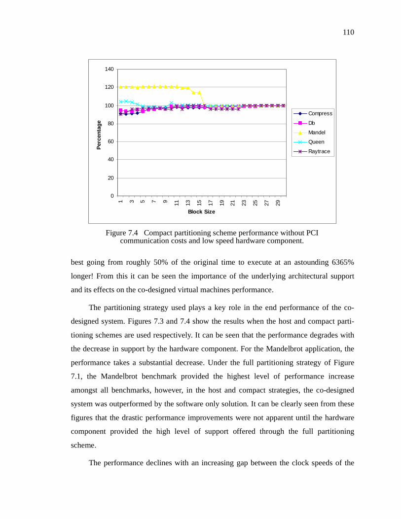
110
best going from roughly 50% of the original time to execute at an astounding 6365%
longer! From this it can be seen the importance of the underlying architectural support
and its effects on the co-designed virtual machines performance.
The partitioning strategy used plays a key role in the end performance of the co-
designed system. Figures 7.3 and 7.4 show the results when the host and compact parti-
tioning schemes are used respectively. It can be seen that the performance degrades with
the decrease in support by the hardware component. For the Mandelbrot application, the
performance takes a substantial decrease. Under the full partitioning strategy of Figure
7.1, the Mandelbrot benchmark provided the highest level of performance increase
amongst all benchmarks, however, in the host and compact strategies, the co-designed
system was outperformed by the software only solution. It can be clearly seen from these
figures that the drastic performance improvements were not apparent until the hardware
component provided the high level of support offered through the full partitioning
scheme.
The performance declines with an increasing gap between the clock speeds of the
0
20
40
60
80
100
120
140
1 3 5 7 9 11 13 15 17 19 21 23 25 27 29
Block Size
Per
cen
tag
e
Compress
Db
Mandel
Queen
Raytrace
Figure 7.4 Compact partitioning scheme performance without PCI communication costs and low speed hardware component.

111
physical host processor and the FPGA. Figure 7.5 shows the performance of the co-
designed machine under ideal conditions, assuming a 1:5 clock ratio, that is, the FPGA
runs at a clock rate 5 times slower than the host processor. For example, a host system
that has a 500 Mhz processor and an FPGA that is 100 Mhz. It can be seen from this dia-
gram, in comparison to Figure 7.1 which had equal clock rates, the performance has
dropped significantly. Previously all benchmarks had shown instances of an initial
improvement of two-fold or better. With the reduced clock rate some applications are
showing a nominal increase in performance. This is highlighted especially by the ray-
trace application which previously showed a 50% improvement to now just 13%! It is
prudent to remember however that this comparison assumes the application utilizes all of
the clock cycles available in software. This is definitely not the case as software cycles
will be lost to both the operating system and other applications.
The following sections discuss the underlying architecture support for the co-
designed system with respect to the effects of reducing the support available to the co-
designed virtual machine and identifying the critical thresholds where support must exist
0
20
40
60
80
100
120
1 3 5 7 9 11 13 15 17 19 21 23 25 27 29
Block Size
Per
cen
tag
e
Compress
Db
Mandel
Queen
Raytrace
Figure 7.5 Co-designed virtual machine timings with no PCI communication costs, under full partitioning and 1:5 clock rate ratio.

112
for a performance increase. These discoveries can be used to outline requirements of an
ideal architecture to support this co-design approach.
7.3 FPGA Performance Requirements
When examining the results of the co-designed virtual machine looking for insights
into the required performance of the FPGA device, two factors must be addressed,
namely the computing speed and design space. The next two subsections address these
requirements.
7.3.1 Speed Requirements
It is obvious that the faster the FPGA the better. What is unclear is the threshold for
how fast the FPGA must be in order to provide a performance increase. For discussion of
the required speed for the FPGA, the speed relationship between the FPGA and host CPU
will be used.
To simplify the investigation, each of the benchmark results was examined without
the communication costs. In these cases, a performance increase was seen for all of the
benchmarks, but not for all FPGA speed ratios. This can be seen for all benchmarks in
Appendix D1, however Figure 7.6 highlights the Mandelbrot application under the com-
pact partitioning. At its peak performance point, with a 1:1 speed ratio FPGA, the Man-
delbrot application, using a block size of 13, completes in just under 20 billion (2E+10)
hardware cycles. However when using a low speed hardware component, 1:5, the perfor-
mance drops below the software only time of 77 billion (7.7E+10) to 91 billion
(9.1E+10). Thus, the application changes from a dramatic performance increase to a
decrease in performance over the software only solution when using a low speed hard-
ware device. Table 7.1 shows for each benchmark and partitioning scheme the threshold
FPGA speed ratio, using a block size of 1 with no communication. These ratios indicate
the maximum number of cycles the software host processor can execute for each single
cycle the hardware design can execute. If the software processor can execute a higher
1. Specifically Appendix D, sections D.1.2, D.2.2, D.3.2, D.4.2, and D.5.2.

113
number of cycles for each cycle the FPGA can execute, then a performance decrease will
be seen. If the software processor executes fewer cycles than the threshold for each cycle
executed by the FPGA then a performance increase will occur.
Traditionally, FPGA speeds have been three to five times slower than that of pro-
cessor speeds [53]. With an FPGA that is up to a factor of five times slower than the host
processor a performance increase is possible for almost all of the results shown in the
table. It can be clearly seen that the lowest threshold value is that of the Mandelbrot
application under the compact and host partitioning schemes. Even in this case, the ratio
is within the traditional bounds of the speed offerings of FPGAs. These results show that
current available speeds of FPGAs are potentially capable of being used in this capacity.
Compress Db Mandelbrot Queen Raytrace
Compact 5.75 5.47 4.12 4.70 6.29
Host 5.78 6.24 4.12 5.47 6.34
Full 7.19 7.43 53.30 8.32 6.37
Table 7.1. Threshold FPGA: Host speed ratios.
0
1E+10
2E+10
3E+10
4E+10
5E+10
6E+10
7E+10
8E+10
9E+10
1E+11
1 3 5 7 9 11 13 15 17 19 21 23 25 27 29
Block Size
Du
rati
on
1:1
1:3
1:5
SW only
Figure 7.6 Mandelbrot application demonstrating effects of different raw computing speeds.

114
7.3.2 Space Requirements
Though not a focal point of this dissertation, the results obtained can be used to
project some insights into the required size of the FPGA and the partitioning scheme it
must be capable of supporting. Examining all of the graphs in Appendix D it can be seen
that the performance of the co-designed virtual machine increases with the greater level
of hardware support. From the previous table, it can be seen that for each benchmark the
Full partitioning scheme outperforms the Host partitioning scheme, which in turn outper-
forms the Compact partition. Thus, in general, the larger the FPGA the greater the perfor-
mance increase.
This is only true, however, when the communication costs are negligible. When the
communication costs rise to a significant level, the driving characteristic behind a parti-
tioning’s success is its ability to provide a low number of context switches, which is indi-
rectly determined by the partitioning scheme, and directly by the density of the
instructions supported in hardware.
While this does not provide a gate measurement of the required FPGA size, it does
show that the required size of the FPGA is dependent on the speed of the FPGA. Having
a slow FPGA requires a larger hardware design space for a performance increase to be
attained. Likewise, a fast FPGA does not require as large a design space area. A prime
example of this is the Mandelbrot application. Provided that the FPGA can support the
design space required of the Full partitioning scheme, a performance increase can be
obtained despite as large a difference in clock ratio of 53:1, as shown in Table 7.1. For the
host system that was used in this research, a 750 Mhz Intel Pentium, that translates into a
required minimum 15 Mhz FPGA. Likewise, Figure 7.6 shows that despite the FPGA
only supporting a small hardware partition, a performance increase can still be seen if the
FPGA is fast. Thus, it is clear the speed and size of the FPGA are linked together.

115
7.4 Hardware/Software Memory Requirements
For the co-designed virtual machine, performance can be affected by the memory
space that is available for the hardware and software components. In the development
environment used, the memory space utilized is not unified, but rather split between each
components local memory region. For the software partition of the virtual machine the
available memory space is not an additional concern because it would provide the same
memory resources available to a software only virtual machine. However, for the co-
designed virtual machine, the distinct local memory available to the FPGA is typically
constrained and may present problems. In the event that not enough memory is available
to the hardware component then execution would remain in software, thus under utilizing
the hardware partition.
In the case study Java virtual machine, the amount of data transferred between the
hardware and software components during execution of each of the benchmarks was
recorded. For all of these benchmarks, the maximum amount of data used by the hard-
ware partition was 11312 bytes. This includes the method to execute, the local data vari-
ables, and the data stack with sufficient room for growth to the maximum stack size. The
common amount required for all benchmarks and partitioning is most likely a result of the
same underlying Java API method being executed by all benchmarks. Though the spe-
cific memory requirements are application dependent, this demonstrates that in general
for the Java virtual machine the memory requirements for the hardware component are
substantially low considering the available 4 Mb of local memory in this particular devel-
opment environment.
7.4.1 Host Memory Accessing Requirements
When examining a strategy for partitioning the instruction set between hardware
and software, it was decided to provide a different partitioning scheme based on the hard-
ware component being capable of directly accessing the host systems memory. This deci-
sion also allows one to use reconfigurable elements that could not provide the design
space support needed in hardware for the added functionality. For the development envi-
ronment that was targeted, the ability to access the host memory system was not present.

116
The development environment provided only allowed for the hardware partition to act as
a PCI target and not as a PCI master device. Given the capability to have the hardware
design function as a PCI master device would provide it with the functionality to access
the host’s main memory system [53,48]. There are other possible arrangements as well
that can provide this capability. In this case, to allow for exploration of the effect of vari-
ous approaches, the simulator was built with the capability of using a PCI as a master.
For the purposes of simulation, the protocol for accessing the host memory system
was treated identically to accessing the local memory on the PCI card. This protocol has a
3 cycle delay associated with it for enabling the memory and setting the requested
address. With this specification the co-designed performance results were collected.
These results can be used to determine for each of the benchmarks the delay that can be
tolerated before the execution crosses the threshold and degrades performance. Figure 7.7
shows the threshold number of cycles for each of the benchmarks under the full partition-
ing scheme where accessing the host memory system is vital. If the delay in accessing the
host memory is above the threshold value, then the application will execute slower in the
co-designed virtual machine. This figure does not factor in the on-chip caching of data
once it is initially accessed by the hardware component. Included in the figure are the dif-
ferent thresholds for each of the performance ratios between raw computing elements
which have a direct affect.
These results show that accessing a common memory store with a delay is tolerable.
However due to how frequently the memory is accessed, the co-designed virtual machine
can only tolerate an average delay of up to 50 cycles for each access. Beyond this delay
performance begins to degrade in comparison to the software execution. It suffices to say
that the development environment used which requires accessing the host memory
through the PCI bus is not viable. Tests showed that an average of 8760 cycles was
required to retrieve a 32-bit word of data across the PCI bus. It is only through the use of
the on-chip data cache that the Mandelbrot application is capable of tolerating the slow
PCI bus to provide a performance increase.

117
7.4.2 Constant Pool Memory
During the design and implementation process of the hardware and software inter-
face, it was decided not to provide the constant pool to the hardware component through
its local memory. Instead, it was decided that the constant pool be accessible through the
host system’s memory. This decision was made on the basis that the penalty for access-
ing the constant pool over the PCI bus would be outweighed by the cost of transferring
the constant pool on each context switch, even when the constant pool may be empty. If
the application frequently uses the constant pool, then transferring the constant pool to the
hardware component’s local memory on each context switch would be practical. How-
ever, this is not the general case as an examination of the benchmarks showed that only
0.28% of the instructions are constant pool accesses [35]. Another factor is that the con-
stant pool accessing instructions are quick instructions. During the initial execution of an
instruction’s instance, execution must be passed back to the software partition for the vir-
tual machine to resolve the constant pool entry. Because of the low number of instruc-
tions that access the constant pool, and their infrequent usage, providing the constant pool
through the host system’s memory is the potential optimal solution for general applica-
tions. It is still beneficial to provide the instructions that access the constant pool through
the hardware partition. Providing the instructions through the hardware partition also con-
0
100
200
300
400
500
600
Har
dw
are
cycl
es
Compress Db Mandelbrot Queen Raytrace
1:1
1:3
1:5
Figure 7.7 Threshold values for communication delays of accessing memory from the host system.

118
tributes towards reducing the number of context switches between hardware and soft-
ware. In general, it is obvious that maintaining the execution in hardware at the penalty of
communicating a constant pool entry is much more desirable than shifting execution back
to software.
This is demonstrated in Table 7.2. which details the number of constant pool
accesses, the number of context switches (or constant pool transfers when caching) and
the average size in bytes of the constant pool for each of the benchmark applications.
These can be used to demonstrate if caching the constant pool for the hardware compo-
nents usage is worthwhile. For all benchmarks, with the exception of the Mandelbrot
application, the combined low usage of the constant pool versus the high number of con-
text switches does not warrant caching the constant pool. However for the Mandelbrot
application, the lower ratio of context switches to constant pool accesses makes the idea
of caching the constant pool very worthwhile. This indicates that the caching of the con-
stant pool is dependent on the application. For this reason, it is difficult to predict the gen-
eral case for how to handle the constant pool.
7.5 Hardware/Software Communication Requirements
With the tight relationship between the hardware and software components, it is
extremely important that the communication link between them be fast. In the event that
the communication medium is relatively slow, any performance gains achieved by hard-
ware execution over software execution can be overshadowed. The demands on the com-
munication speed are dictated by the application running within the virtual machine, and
Compress Db Mandel Queen Raytrace
Accesses 8280 18473 27604814 12954 4329684
Transfers 87592734 279818663 22604 110499 728683932
Avg. Size 382.96 936.51 1395.94 646.47 386.73
Bytes/Access 4051230.7 14185695.5 1.143 5514.4 65085.7
Table 7.2. Constant pool caching efficiency measurements.

119
are thus very instance specific. If the application demands frequent execution migration
and high levels of data exchange between the hardware and software components, then
the more critical the demands on the communication medium.
It was seen in Section 7.2 that the addition of the hardware components into the vir-
tual machine can provide an increase in performance. However, for the targeted develop-
ment environment, the PCI bus proves to be too slow for the case study Java virtual
machine for most applications. Table 7.3 shows the execution times, including the com-
munication penalties, for the benchmarks in the co-designed virtual machine with a full
partitioning scheme and a 1:5 clock ratio between the hardware and software devices.
Only one of the benchmarks, Mandelbrot, shows a significant performance increase
despite the communication costs of the PCI bus and this is due to certain characteristics
of the application itself. Most other benchmarks show a high performance decrease
because of the communication costs.
Block Compress Db Mandel Queen Raytrace
1 2287% 1900% 11.3% 171% 6365%
2 2277% 1836% 11.3% 166% 5052%
3 2190% 1668% 11.2% 162% 2624%
4 2090% 1442% 11.2% 156% 2598%
5 1652% 1113% 10.8% 137% 2276%
6 1566% 1123% 10.8% 137% 2747%
7 1325% 894% 10.8% 136% 2499%
8 952% 893% 10.6% 131% 2353%
9 879% 741% 10.6% 130% 2381%
10 769% 551% 10.6% 110% 3795%
11 737% 552% 10.6% 109% 1032%
12 684% 553% 10.7% 120% 5057%
13 386% 550% 11.0% 127% 4853%
14 386% 561% 11.0% 103% 144%
15 389% 678% 11.0% 103% 146%
16 387% 681% 10.9% 103% 146%
17 389% 559% 10.9% 102% 145%
Table 7.3. Percentage of original execution times with full partitioning scheme and 1:5 FPGA:Host ratio, including communication delays.

120
One can also see from Table 7.3, the importance of context switching and the over-
lap in support between the hardware and software partitions. When there is no overlap
between the hardware and software partitions (the block size equals 1) performance is at
its worst. As the block size becomes significant enough to compete against the costs of
the context switch the performance improves. This supports the idea of having an over-
lap between the partitions and the need for smart run-time determination of context
switching between them.
This can also be supported by the average number of hardware cycles executed per
context switch, which provides a measurement of both the frequency and density of the
instructions to be executed in the hardware component. The worst case for hardware
cycles per context switch is when the block size is one. This is due to the high number of
context switches that take place for execution of a single instruction in hardware. Table
7.4 shows, for the same tests with a block size of 1, that the higher the number of hard-
ware cycles per context switch, the greater the performance gains. This is true in general,
but is also dependent on both the types of instructions and the ordering. The Mandelbrot
benchmark under a Full partitioning provides the only performance gain, despite the
18 387% 564% 10.9% 103% 145%
19 389% 561% 10.9% 103% 160%
20 388% 546% 11% 102% 161%
21 387% 544% 10.6% 109% 160%
22 402% 668% 10.6% 116% 122%
23 404% 666% 10.6% 116% 122%
24 626% 864% 10.6% 122% 122%
25 626% 861% 10.7% 121% 122%
26 1102% 864% 10.3% 113% 122%
27 1097% 861% 10.2% 113% 122%
28 1120% 861% 10.0% 112% 122%
29 1105% 860% 10.0% 117% 166%
30 1101% 849% 10.0% 118% 166%
Block Compress Db Mandel Queen Raytrace
Table 7.3. Percentage of original execution times with full partitioning scheme and 1:5 FPGA:Host ratio, including communication delays.

121
overwhelming communication overhead, of 42161.71 hardware cycles per context
switch. While as shown by this test that such instruction density is possible, it may not be
representative of the average density for most applications.
Examining the Queen benchmark in Table 7.3, using a block size from 17 to 20, the
execution is close to matching the hardware cycles per context switch threshold required
to obtain a performance gain. In this case, the average number of hardware cycles per
context switch is 8299 with an average of 879.94 instructions per context switch. Though
these numbers are dependent on both the type and ordering of instructions, it does pro-
vide a rough estimate of the hardware support density needed to begin obtaining a perfor-
mance increase.
There are several underlying reasons for the PCI bus being unsuitable for usage in a
co-design virtual machine environment. The most obvious problem is that the bus is
shared with other devices. Sharing the bus results in unnecessary delays when waiting for
the bus arbitrator to hand over control of the bus. This is especially true when the PCI bus
typically holds relatively high bandwidth hardware components such as the audio, video
and network devices. In comparison with the relative speeds of the hardware and software
computing elements, the PCI bus is exceptionally slow. For the specific development
environment used in the case study, the PCI bus operates at 33 Mhz, while the FPGA
operates at speeds up to 100 Mhz and the host processor at a much bigger 750 Mhz. With
such a high disparity between the communication and operating speeds the necessary
communication between the partitions results in a drastic performance penalty.
While the idea of providing the FPGA that implements the hardware design on a
bus that has comparable speeds with that of the FPGA itself or the software processor
may not be feasible, a better overall architecture is certainly more attainable. Ideally, to
have the FPGA device directly attached to the mainboard of the host system on a dedi-
Partitioning Compress Db Mandel Queen Raytrace
Compact 30.88 38.57 59.89 25.05 24.10
Host 28.13 37.10 59.86 28.60 24.18
Full 128.63 133.86 42161.71 2615.92 32.75
Table 7.4. Average number of hardware cycles/context switch for each benchmark.

122
cated bus would provide a considerable improvement. Likewise, to have a fast communi-
cation bus between the FPGA and the host’s memory is also beneficial. As can be seen
from the results in the previous section, the co-designed machine does promise varying
performance gains for each of the benchmarks without the communication penalty. This
demonstrates that for this approach to succeed in general a more suitable architecture
must be present.
7.6 Application Identification
As with all computing platforms, the Java virtual machine included, there are smart
ways of programming for the target platform [36]. Specifically though, for the co-
designed machine to provide improved performance it is clear that the underlying archi-
tecture support must meet certain requirements. It can also be seen that despite the under-
lying architectural support certain benchmarks achieve better performance increases than
others. Table 7.5 shows an example of this instance. This table shows the percentages of
the original software execution time taken for each benchmark under ideal architectural
support conditions in the co-designed virtual machine, where the block size is 1 since this
combination provides the greatest performance increases for all benchmarks. Under sup-
posedly ideal conditions the Mandelbrot application achieves a significantly greater per-
formance increase than the Raytrace application.
This is attributed to inherent characteristics of the applications. There are two key
low level characteristics that affect the suitability of an application for execution in a co-
designed virtual machine. First, the application should contain a high percentage of
instructions supported by the hardware partition; secondly, the instructions should be
densely located, in order to have a low number of context switches. This reduces down to
a simple guideline that the higher the instructions per context switch ratio, the higher the
potential increase offered by execution in a co-designed virtual machine.
Compress Db Mandel Queen Raytrace
22.4% 31.3% 2.3% 16.2% 49.5%
Table 7.5. Optimal performance increases under ideal conditions.

123
Table 7.6 shows the percentage of instruction coverage, the number of context switches,
and the instruction per context switch ratio for each application under the full partitioning
scheme. It can be seen directly from this table and the performance increases from Table 7.5
that this relationship exists. The higher the number of instructions per context switch, the
greater the performance increase. However, the level of performance increase is not propor-
tional to the number of instructions per context switch since the types and ordering of instruc-
tions that are executed also have an effect on performance. The gains of executing different
instructions in hardware over software are not equal, nor proportional. Additionally, the
ordering directly affects the instruction pipelining and the gains achieved.
7.6.1 High-Level Application Characteristics
With some knowledge of the characteristics at a low level for an application to have a
potential performance increase, one can expand to identify high-level properties. From the
Mandelbrot application it was seen that ideal low-level properties of an application would
include instructions that are supported by the hardware component, and that these instruc-
tions be densely located.
Chapter 4 discussed the partitioning strategies and identified low-level instructions that
are to be supported by the software partition. From this, it can be seen that the software parti-
tion is mostly composed of object management and manipulation instructions. This includes
instructions such as new, newarray, checkcast, invokespecial, and invokevirtual. These
instructions are rather directly linked to operations in the higher-level Java language. For
example, there exists a “new” method in the Java language that once compiled directly maps
into either the new, newarray, or anewarray bytecode operation of the Java virtual machine.
Thus, an application that is more suitable for co-designed execution will possess fewer object
Compress Db Mandel Queen Raytrace
% Instructions 92.1% 91.2% 99.9% 99.7% 69%
# Context Switches
87905848 282819658 34061 164120 952247321
Instructions/Context switch 12.42 12.67 40435.3 275.36 1.98
Table 7.6. Instruction support and density for various benchmarks.

124
management and manipulation properties.
To support this insight, both the Mandelbrot and Raytrace applications are exam-
ined to determine how much object management and manipulation exists within their
source code. These two applications were chosen since they provided both the best and
worst performance increases in the co-designed Java virtual machine. One simple mea-
surement is the number of classes that are defined in each application, and how often
these classes are instantiated. For Mandelbrot, there are 3 classes, while there are 25
classes in the Raytrace benchmark. This does not include standard inherited classes such
as Object. When executing, the Mandelbrot application creates a total of 1,079 object
instances, where Raytrace creates a total of 9,827,973 object instances.
This is best characterized by Figures 7.8 and 7.9 which show the critical sections of
code for both applications. It can be clearly seen that the Mandelbrot application’s criti-
cal section contains no object manipulation (the window array referenced is an array of
primitive integers). Whereas the Raytrace application has its critical section full of object
references and manipulations. Within the innermost loop, there are 9 object manipulations
and 1 object creation, bolded for clarity in the figure. With the heavy object manipulation
it can be clearly anticipated that heavy context switching would occur between hardware
and software during execution. This demonstrates the underlying characteristics that are
desirable for an application to achieve increased performance in the co-designed virtual
machine. One should minimize object manipulation by using primitive types wherever
possible, but when it is unavoidable, object manipulation tasks should be clustered
together outside the critical loop.
7.7 Summary
This chapter has presented the performance results of the co-design approach for
virtual machines discussed in this dissertation as applied to the Java virtual machine. The
results presented show that there can exist a performance increase over a simple software
only execution scheme. However, this performance increase is dependent on the correct
architectural environment and on the characteristics of the applications. From the results

125
it can be seen that certain memory, FPGA and communication requirements exist for this
design to succeed. The results of various benchmark applications and how they per-
formed within the co-designed virtual machine were used to gain an insight into any spe-
cific types and features of Java applications that would benefit from running in a co-
designed virtual machine.
public void mandelbrot(){
double dx, dy, x, y, cr, ci, zr, zi, zsqr, zsqi;double radsqrd = radius * radius;int j, p, i;
dx = (xmax - xmin) / cols;dy = (ymax - ymin) / rows;x = xmin - dx / 2;for (j = 0; j < cols; j++){
x = x + dx;y = ymin - dy / 2;
for (i = 0; i < rows; i++){
y = y + dy;cr = x;ci = y;zi = zr = 0;
p = 0;while ((p < iter)&&(zr*zr + zi*zi < radsqrd)){
p++;zsqr = zr * zr - zi * zi;zsqi = 2 * zr * zi;zr = zsqr + cr;zi = zsqi + ci;
}
if (p == iter)window[i][j] = 0;
elsewindow[i][j] = (p / 100) + 1;
}}
}
Figure 7.8 Critical section of Mandelbrot application.

126
public void RenderScene(Canvas canvas, int width, int section,int nsections){
Vector view = camera.GetViewDir(), up = camera.GetOrthoUp();Vector plane = new Vector(), horIncr = new Vector();Vector vertIncr = new Vector();float ylen = camera.GetFocalDist() *(float)Math.tan(0.5f*camera.GetFOV());float xlen = ylen * canvas.GetWidth() / canvas.GetHeight();Point upleft = new Point(), upright = new Point();Point lowleft = new Point(), base = new Point(), current;Ray eyeRay = new Ray();int ypixel, xpixel, xstart, xend;
RayID = 1;plane.Cross(view, up);view.Scale(camera.GetFocalDist());up.Scale(ylen); plane.Scale(-xlen);upleft.FindCorner(view, up, plane, camera.GetPosition());plane.Negate();upright.FindCorner(view, up, plane, camera.GetPosition());up.Negate(); plane.Negate();lowleft.FindCorner(view, up, plane, camera.GetPosition());horIncr.Sub(upright, upleft);horIncr.Scale(horIncr.Length() / ((float) canvas.GetWidth()));vertIncr.Sub(lowleft, upleft);vertIncr.Scale(vertIncr.Length() / ((float)canvas.GetHeight()));base.Set(upleft.GetX()+ 0.5f * (horIncr.GetX()+vertIncr.GetX()),upleft.GetY() + 0.5f * (horIncr.GetY() + vertIncr.GetY()),upleft.GetZ() + 0.5f * (horIncr.GetZ() + vertIncr.GetZ()));eyeRay.SetOrigin(camera.GetPosition());xstart = section * width/nsections;xend = xstart + width/nsections;for (ypixel = 0 ; ypixel < canvas.GetHeight(); ypixel++){
current = new Point(base);for (xpixel = 0; xpixel < canvas.GetWidth(); xpixel++){
if (xpixel >= xstart && xpixel < xend){Color color = new Color(0.0f, 0.0f, 0.0f);eyeRay.GetDirection().Sub(current, eyeRay.GetOrigin());eyeRay.GetDirection().Normalize();eyeRay.SetID(RayID++);Shade(octree, eyeRay, color, 1.0f, 0, 0);canvas.Write(Brightness, xpixel, ypixel, color);
}current.Add(horIncr);
}base.Add(vertIncr);
}}
Figure 7.9 Critical section of Raytrace application.

CHAPTER 8
Conclusions Chapter 8
8.1 Summary
The prominence of the internet and networked computing has driven research
efforts into providing support for homogeneous computing. This has been exemplified by
the current research into virtual machines, a case in point being the Java virtual machine.
Unfortunately, it has long been accepted that with virtual computing platforms and the
ability to “write once, run anywhere” comes the penalty of performance. This disserta-
tion presents a new hardware/software co-design approach for providing virtual comput-
ing platforms through the use of reconfigurable computing devices. This novel approach
promotes the philosophy that user applications remains portable, while achieving a per-
formance increase.
Chapters three through five discuss specifically how the co-design process can be
applied to the class of virtual machines in a structured approach. This replaces the
instance specific techniques that are often used within each of the co-design stages. The
dissertation demonstrates that a structured partitioning, hardware, software, and interface
design approach can result in a winning co-designed virtual machine. Novel ideas in these
approaches are presented including the overlapping of hardware and software partitions, a
generic hardware design, and algorithms for controlling execution location at run-time.
Simulation showed that under ideal conditions for certain benchmarks it attained as high
as a nine-fold performance increase. The effects of the physical environment on this per-
formance is also included. Specifics such as the required size and speed of the program-
mable device, the memory system, and the communication are addressed. This results in
the description of the requirements needed for this approach to be successful. This
includes:
• An FPGA large enough to support the Full partitioning scheme described.

128
• An FPGA that can perform at least within a 1:5 speed ratio of the general-
purpose processor can provide significant performance gains.
• A memory system that does not need to be extremely large, as studies
showed 1 Mb will suffice, but must be accessible by both processing
devices and capable of operating at a high rate, fewer than 50 clock cycles
per access.
• A fast communication bus between the FPGA and the general purpose pro-
cessor. It was shown that the communication penalty is too much unless the
hardware component executed approximately 8300 cycles.
The following sections outlines the major contributions of this research and dis-
cusses some of the future work that can branch from the research presented in this disser-
tation.
8.2 Contributions
This dissertation has introduced and addressed the original concept of using hard-
ware/software co-design as a means for providing virtual machine platforms. Specifi-
cally it described a new approach that extends the generally accepted co-design process
for all systems. Stages in the co-design process such as partitioning, design of both the
hardware and software components, and the inherent interface between them were
described.
The new contributions succeed in linking the general co-design process that is well
established, and described in chapter three, with the specific co-design of virtual
machines. It discusses specific techniques for each of the various stages of the general co-
design process, including:
• Partitioning. The dissertation presents the partitioning strategy of dividing
the functionalities between the hardware architecture and the operating
system. While this is only one of many possible partitioning strategies, it is
extendable to other virtual machines, and was demonstrated to contribute
to a successful co-design for the example Java virtual machine. Addition-
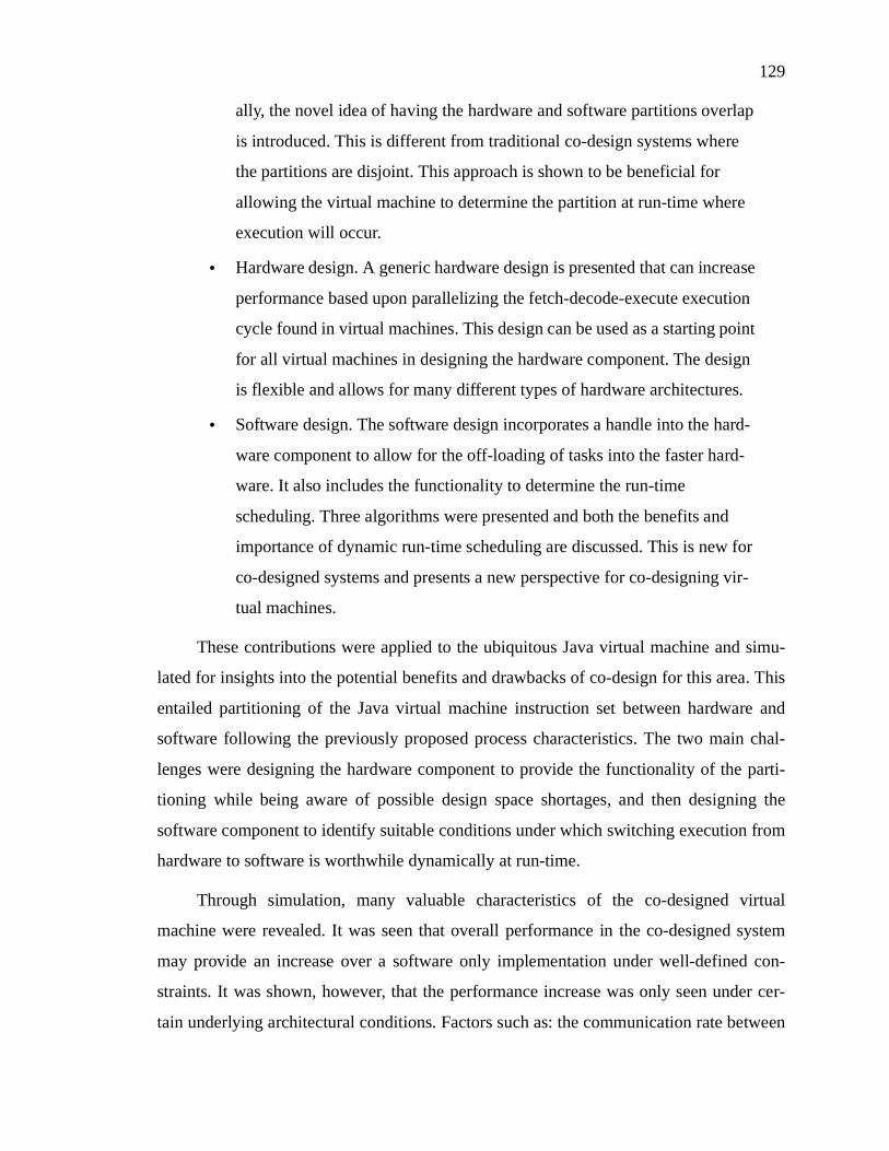
129
ally, the novel idea of having the hardware and software partitions overlap
is introduced. This is different from traditional co-design systems where
the partitions are disjoint. This approach is shown to be beneficial for
allowing the virtual machine to determine the partition at run-time where
execution will occur.
• Hardware design. A generic hardware design is presented that can increase
performance based upon parallelizing the fetch-decode-execute execution
cycle found in virtual machines. This design can be used as a starting point
for all virtual machines in designing the hardware component. The design
is flexible and allows for many different types of hardware architectures.
• Software design. The software design incorporates a handle into the hard-
ware component to allow for the off-loading of tasks into the faster hard-
ware. It also includes the functionality to determine the run-time
scheduling. Three algorithms were presented and both the benefits and
importance of dynamic run-time scheduling are discussed. This is new for
co-designed systems and presents a new perspective for co-designing vir-
tual machines.
These contributions were applied to the ubiquitous Java virtual machine and simu-
lated for insights into the potential benefits and drawbacks of co-design for this area. This
entailed partitioning of the Java virtual machine instruction set between hardware and
software following the previously proposed process characteristics. The two main chal-
lenges were designing the hardware component to provide the functionality of the parti-
tioning while being aware of possible design space shortages, and then designing the
software component to identify suitable conditions under which switching execution from
hardware to software is worthwhile dynamically at run-time.
Through simulation, many valuable characteristics of the co-designed virtual
machine were revealed. It was seen that overall performance in the co-designed system
may provide an increase over a software only implementation under well-defined con-
straints. It was shown, however, that the performance increase was only seen under cer-
tain underlying architectural conditions. Factors such as: the communication rate between
130
the hardware and software components; the size and speed of the physical hardware com-
puting device; and the design and size of the memory subsystem specifically affected the
performance. Each of these factors were investigated separately to identify the threshold
levels of each and the minimum support required to obtain a performance increase.
Finally, a proposal for an ideal, yet currently technically achievable architecture was pro-
posed and will be expanded in the future.
This work has demonstrated a capability of extended use for reconfigurable devices.
It has also derived some of the required performance capabilities and support needed for
reconfigurable computing to be capable of supporting co-designed virtual machines. As
such, reconfigurable computing can be used for more general computing, not for just very
specific problem instances.
8.3 Future Work
This dissertation has introduced the use of hardware/software co-design and recon-
figurable computing for use as a general computing platform. There is considerable work
that can be extended from the results presented, including obvious extensions that can be
followed such as applying the hardware/software co-design contributions to other virtual
machine platforms. There are however three other distinctive streams which further work
can follow and for which the current research provides a strong and valuable start.
First, further investigation can be carried out towards targeting applications for this
computing platform. It was demonstrated that the underlying characteristics of applica-
tions affect the performance. This is true regardless of the underlying virtual machine
implementation. Much research has been done to massage applications for improved per-
formance with just-in-time compilation technologies or for dedicated hardware execu-
tion, such as picoJava, or through advanced topics such as bytecode re-ordering and
branch instruction prediction. While some of this research can be carried over to improve
performance within a co-designed virtual machine, there are unique features of the co-
design platform that must also be investigated further for exploitation. One example is to
further investigate the context switching to find better techniques that can be used at com-

131
pile-time. Another is to examine selective bytecode usage, replacing bytecode instruc-
tions with other instructions, or combinations of, that are more desirable for execution in
hardware.
A second area for further research concerns the effects of parallelism. The research
to date has focused on the performance increases attained because of dedicated hardware
support over software interpretation. The work did not address the increases available
because of parallel execution. This is primarily due to the complexities involved with
simulating parallel execution. With the added hardware support, it is possible to have
both the dedicated hardware and host system processor working in parallel on executing
the application. This research is of considerable value in the event the specific virtual
machine being targeted is multi-threaded. Under this condition, additional performance
increases can be envisaged.
Finally, this work has identified characteristics of the underlying hardware architec-
ture that would promote hardware/software co-design for use in providing virtual
machines. Traditionally, reconfigurable computing has been used for the embedded sys-
tems market and/or very constrained instance specific problems. Thus the architectural
environments available today are not entirely suitable for co-designed virtual machines.
Knowing the desirable features, the development of a suitable architectural environment
would be invaluable. The availability of such a development environment would not only
allow a suitable platform for validation and verification of co-designed virtual machines,
but will also ignite further research in the area.

APPENDIX A
Java Virtual Machine Bytecode Statistics Appendix A
This appendix presents several quantitative execution measurements of the various
Java bytecodes within each of five different benchmarks. The bytecode size is the number
of bytes that comprise the opcode and operands. The execution time is the average num-
ber of clock cycles required to execute each of the instruction instances in the bench-
marks1. For instructions that have a quick version, the times given is the amount required
to perform the necessary class loading. It is at this time the quick version of the instruc-
tion is invoked.
These numbers are affected by external operating system events and other anoma-
lies during execution. Therefore, these execution times should only be considered as
approximations. The data traffic is the number of memory accesses necessary for execu-
tion. The results presented are broken into both local and remote memory accesses. For
this purpose, local is considered to be access to the execution stack and the local vari-
ables, all other accesses are considered remote. Finally, the frequency is the number of
times each instruction is encountered during execution for each benchmark.
1. Clock cycles are measured in relation to a Pentium III 750 Mhz processor running Windows 2000. These results are acquired by capturing the processors time stamp counter.
Bytecode
Bytecode Size
Exec Time
Data Traffic Frequency
L R Comp. Db Mandel. Queen Raytrace
000 1 0 0 0 0 0 0 0 0
001 1 33 1 0 654 18086 629 629 1726285
002 1 31 1 0 5796801 19228 38 350835 494270
003 1 32 1 0 5233568 6126360 175762 358297 20827135
004 1 31 1 0 31956497 86049821 60822 1694093 13452389
005 1 40 1 0 2838 3904 2822 3560 1867930

133
006 1 38 1 0 3761141 6 7 7 2056027
007 1 40 1 0 11 174 9 12 1676743
008 1 32 1 0 91 130 87 86 1792564
009 1 77 2 0 12 12 6 6 10
010 1 42 2 0 0 1 0 0 2
011 1 42 1 0 12 12 12 12 20965309
012 1 10 1 0 0 0 0 0 14922803
013 1 13 1 0 0 0 0 0 1122
014 1 45 2 0 0 0 76800 0 0
015 1 27 2 0 0 0 1 0 1
016 2 32 1 0 20773745 2780107 65302 13553 3420632
017 3 31 1 0 10321577 1021651 4464 4438 351826
018 2 606 1 V 583 593 573 577 626
019 3 843 1 V 499 499 499 499 499
020 3 133 2 V 2 3 8 2 62
021 2 31 2 0 62950618 450603215
37557946 49559 7119731
022 2 0 4 0 0 0 0 0 0
023 2 30 2 0 0 0 0 0 49001383
024 2 34 4 0 0 0 556939890
0 0
025 2 31 2 0 7159 194338315
7135 1025244 41528987
026 1 32 2 0 14312 38356344 14213 19365 45651
027 1 31 2 0 59837754 169754600
104176 3935925 26481309
028 1 31 2 0 73584849 52578319 161097 5189072 5164689
029 1 31 2 0 24013997 155702752
6127 3280856 1985885
030 1 0 4 0 0 0 0 0 0
031 1 48 4 0 8 8 4 4 6
032 1 23 4 0 1 1 0 0 0
033 1 0 4 0 0 0 0 0 0
034 1 30 2 0 24 24 24 24 640096
035 1 28 2 0 0 0 0 0 24780331
036 1 29 2 0 48 48 48 48 20126261
037 1 31 2 0 0 0 0 0 42332123
038 1 27 4 0 0 0 0 0 369785
Bytecode
Bytecode Size
Exec Time
Data Traffic Frequency
L R Comp. Db Mandel. Queen Raytrace

134
039 1 27 4 0 0 0 321 0 0
040 1 0 4 0 0 0 0 0 0
041 1 34 4 0 0 0 77120 0 0
042 1 32 2 0 175217262
331016287
37587286 5833780 553015696
043 1 30 2 0 2277354 96894968 2297 16715 139462175
044 1 30 2 0 2796 13345631 2728 3281 64450743
045 1 30 2 0 6962 12014756 6934 8591 11611092
046 1 58 3 3 12715631 125 120 2494038 281500
047 1 0 4 4 0 0 0 0 0
048 1 46 3 3 0 0 0 0 25628
049 1 0 4 4 0 0 0 0 0
050 1 56 2 V 1995 121228820
155590 3533459 23844681
051 1 44 3 3 22777724 3782684 241 3501 348956
052 1 45 3 3 10973 128661804
10972 17886 365250
053 1 61 3 3 4432071 5239 161 1791 1536
054 2 30 2 0 23580899 266666530
81229 13664 4383556
055 2 0 4 0 0 0 0 0 0
056 2 31 2 0 0 0 0 0 19643326
057 2 48 4 0 0 0 148762430
0 0
058 2 33 2 0 2854 105923807
2794 21150 10493157
059 1 40 2 0 25 51 4 740 14
060 1 33 2 0 9617773 5161 4816 36338 217137
061 1 31 2 0 28523769 22651420 1441 186113 275391
062 1 31 2 0 9743477 47393732 4607 261317 103310
063 1 0 4 0 0 0 0 0 0
064 1 0 4 0 0 0 0 0 0
065 1 53 4 0 1 1 0 0 0
066 1 0 4 0 0 0 0 0 0
067 1 0 2 0 0 0 0 0 0
068 1 0 2 0 0 0 0 0 0
069 1 44 2 0 0 0 0 0 205597
070 1 50 2 0 0 0 0 0 3831619
Bytecode
Bytecode Size
Exec Time
Data Traffic Frequency
L R Comp. Db Mandel. Queen Raytrace

135
071 1 0 4 0 0 0 0 0 0
072 1 54 4 0 0 0 1 0 0
073 1 0 4 0 0 0 0 0 0
074 1 55 4 0 0 0 1 0 0
075 1 40 2 0 27 27 26 26 12881
076 1 34 2 0 199 8200581 155 1351 14383
077 1 32 2 0 228 11126234 204 481 54666
078 1 31 2 0 1092 1466929 1086 1087 3627951
079 1 51 3 3 2199325 632 154271 1038144 600673
080 1 64 4 4 0 0 0 0 2
081 1 47 3 3 0 0 0 0 12842
082 1 55 4 4 0 0 0 0 33
083 1 86 3 V 929 26959793 924 924 2882013
084 1 49 3 3 15131722 11458 1225 4446 1098
085 1 46 3 3 378 1033712 336 1808 397270
086 1 45 3 3 2060006 4288 4288 4288 4288
087 1 31 1 0 483 793 474 1954 4134696
088 1 29 2 0 1 1 0 0 1
089 1 31 3 0 48461046 82242274 3270 8334 11748853
090 1 34 5 0 15835283 8341806 98 2096 587447
091 1 0 7 0 0 0 0 0 0
092 1 29 6 0 0 160 76800 0 0
093 1 0 8 0 0 0 0 0 0
094 1 0 10 0 0 0 0 0 0
095 1 0 4 0 0 0 0 0 0
096 1 33 3 0 35047032 53737271 70283 961450 1048957
097 1 0 6 0 0 0 0 0 0
098 1 59 3 0 0 0 0 0 49746942
099 1 64 6 0 0 0 111418954
0 0
100 1 31 3 0 28409972 116480015
922 598005 167734
101 1 34 6 0 1 1 0 0 0
102 1 56 3 0 0 0 0 0 5305259
103 1 54 6 0 0 0 37094770 0 0
104 1 35 3 0 4190 4259 4191 4190 186527
105 1 0 6 0 0 0 0 0 0
Bytecode
Bytecode Size
Exec Time
Data Traffic Frequency
L R Comp. Db Mandel. Queen Raytrace

136
106 1 124 3 0 16 16 16 16 80452319
107 1 49 6 0 0 0 222683668
0 0
108 1 125 3 0 88 997 58494 737 1425
109 1 0 6 0 0 0 0 0 0
110 1 59 3 0 0 0 0 0 4780911
111 1 29 6 0 0 0 323 0 0
112 1 43 3 0 962 988 941 1677 951
113 1 0 6 0 0 0 0 0 0
114 1 0 3 0 0 0 0 0 0
115 1 0 6 0 0 0 0 0 0
116 1 25 2 0 4 22 0 0 28412
117 1 0 4 0 0 0 0 0 0
118 1 27 2 0 0 0 0 0 4569021
119 1 0 4 0 0 0 0 0 0
120 1 35 3 0 15342015 757 713 713 82132
121 1 0 5 0 0 0 0 0 0
122 1 32 3 0 5886363 6644 1268 2898 5481
123 1 0 5 0 0 0 0 0 0
124 1 35 3 0 4431922 0 0 0 0
125 1 0 5 0 0 0 0 0 0
126 1 34 3 0 12154057 1028850 1343 4603 474315
127 1 150 6 0 1 1 1 1 1
128 1 35 3 0 2716185 1674 1426 1426 124264
129 1 0 6 0 0 0 0 0 0
130 1 105 3 0 3420157 0 0 0 0
131 1 192 6 0 1 1 1 1 1
132 3 32 2 0 15781926 148862307
37267659 2674234 3545408
133 1 72 3 0 0 1 0 0 2
134 1 40 2 0 16 16 16 16 12874
135 1 57 3 0 0 0 3 0 0
136 1 0 3 0 0 0 0 0 0
137 1 0 3 0 0 0 0 0 0
138 1 0 4 0 0 0 0 0 0
139 1 163 2 0 16 16 16 16 120016
140 1 0 3 0 0 0 0 0 0
Bytecode
Bytecode Size
Exec Time
Data Traffic Frequency
L R Comp. Db Mandel. Queen Raytrace

137
141 1 34 3 0 0 0 0 0 369785
142 1 0 3 0 0 0 0 0 0
143 1 0 4 0 0 0 0 0 0
144 1 54 3 0 0 0 0 0 369785
145 1 32 2 0 4947156 6298 1143 2734 1060
146 1 40 2 0 2 1033284 2 2 321768
147 1 29 2 0 2055398 4032 4032 4032 4032
148 1 108 5 0 6 6 4 4 5
149 1 61 3 0 12 12 12 12 21849343
150 1 161 3 0 12 12 12 12 22575612
151 1 0 5 0 0 0 0 0 0
152 1 46 5 0 0 0 37152940 0 0
153 3 35 1 0 4624281 2914402 278 2854 4757175
154 3 35 1 0 6968151 79312383 916 4570 11422445
155 3 32 1 0 3086174 14404 37159020 8170 20410559
156 3 34 1 0 9295588 23333770 145 4285 7518194
157 3 32 1 0 10127442 23648965 550 550 346762
158 3 36 1 0 5977813 2426 25 485 11980868
159 3 33 2 0 251 67354364 242 105038 13248
160 3 34 2 0 18544909 2638553 78642 1513601 7386822
161 3 33 2 0 7411369 58942400 174254 2875313 3761532
162 3 33 2 0 7029538 16655277 37171275 321301 188929
163 3 34 2 0 2407253 22510294 127 193360 27254
164 3 33 2 0 1354485 273519 312 166222 88888
165 3 50 2 0 4 4 0 0 2
166 3 36 2 0 131 1460230 121 121 1200165
167 3 32 0 0 4601153 71279303 98762 476764 1805105
168 3 0 1 0 0 0 0 0 0
169 2 0 1 0 0 0 0 0 0
170 V 175 1 0 1 3 1 1 89564
171 V 57 1 0 0 19587 0 0 347430
172 1 36 1 V 32188115 57595116 6937 31277 33448696
173 1 41 2 V 2 2 0 0 2
174 1 51 1 V 0 0 0 0 223659971
175 1 43 2 V 0 0 0 0 369785
176 1 37 1 V 962 56122152 907 5507 98944369
Bytecode
Bytecode Size
Exec Time
Data Traffic Frequency
L R Comp. Db Mandel. Queen Raytrace

138
177 1 34 0 V 14423471 6498981 2069 9714 54572890
178 3 744 V V 557 559 538 542 554
179 3 1470 V V 122 126 118 118 140
180 3 310 V V 435 414 280 393 633
181 3 621 V V 307 270 213 213 386
182 3 528 V V 703 767 641 660 1418
183 3 1114 V V 304 318 263 289 452
184 3 15050
V V 145 151 127 127 179
185 5 1561 V V 1 13 1 1 1
186 NA 0 NA NA 0 0 0 0 0
187 3 143497
V V 124 135 112 119 225
188 2 5990 V V 246 126540 193 1939 185900
189 3 46871
2 V 19 21 18 19 26
190 1 45 2 1 863 272663 813 3757 26626
191 1 0 2 V 0 0 0 0 0
192 3 226 2 V 20 31 19 19 22
193 3 341 2 V 2 3 2 2 2
194 1 145 1 V 136 8199790 53 1341 64
195 1 229 1 V 134 8199788 51 1339 62
196 6 0 4 0 0 0 0 0 0
197 4 548 V V 0 0 1 8 0
198 3 46 1 0 125 5145 99 99 1520487
199 3 37 1 0 2463 10785 2392 5060 6461318
200 5 0 0 0 0 0 0 0 0
201 5 0 1 0 0 0 0 0 0
202 NA 0 NA NA 0 0 0 0 0
203 2 31 1 1 7779 17972 7721 12453 4329123
204 3 32 1 1 499 499 499 499 499
205 3 30 2 2 2 3 37094773 2 62
206 3 46 2 2 171151631
450719822
37557577 5754069 361886270
207 3 43 2 2 33760188 14729815 232 8280 87411458
208 3 17 3 3 0 0 325 0 0
209 3 36 3 3 0 0 4 0 0
210 3 36 1 2 4057680 7319 6566 8130 36508
Bytecode
Bytecode Size
Exec Time
Data Traffic Frequency
L R Comp. Db Mandel. Queen Raytrace

139
211 3 46 1 2 128 129 120 120 138
212 3 48 2 4 2 2 2 2 2
213 3 41 2 4 0 3 0 0 5
214 3 102 V V 44195415 74998966 268 9879 383020882
215 3 341 V V 2409271 6334687 1839 23477 27364578
216 3 0 V V 0 0 0 0 0
217 3 1444 V V 603 22516130 511 5295 968601
218 5 310 V V 2 14931139 2 2 2
219 3 702 V V 3 1451785 1 1 2
220 NA 0 NA NA 0 0 0 0 0
221 3 173 1 V 761 3061873 710 1633 9372030
222 3 1845 2 V 45 16038 44 45 269792
223 4 23497
V V 0 0 1 15716 0
224 3 80 2 V 89 56120424 87 87 3776670
225 3 113 2 V 64 2909617 64 64 103
226 3 180 V V 7535 8237 7511 10823 24655
227 3 47 3 7 25834 7110837 25769 43815 472833
228 3 48 3 8 4911 52157 4881 6997 4918
229 NA 0 NA NA 0 0 0 0 0
230 NA 0 NA NA 0 0 0 0 0
231 NA 0 NA NA 0 0 0 0 0
232 NA 0 NA NA 0 0 0 0 0
233 NA 0 NA NA 0 0 0 0 0
234 NA 0 NA NA 0 0 0 0 0
235 NA 0 NA NA 0 0 0 0 0
236 NA 0 NA NA 0 0 0 0 0
237 NA 0 NA NA 0 0 0 0 0
238 NA 0 NA NA 0 0 0 0 0
239 NA 0 NA NA 0 0 0 0 0
240 NA 0 NA NA 0 0 0 0 0
241 NA 0 NA NA 0 0 0 0 0
242 NA 0 NA NA 0 0 0 0 0
243 NA 0 NA NA 0 0 0 0 0
244 NA 0 NA NA 0 0 0 0 0
245 NA 0 NA NA 0 0 0 0 0
Bytecode
Bytecode Size
Exec Time
Data Traffic Frequency
L R Comp. Db Mandel. Queen Raytrace
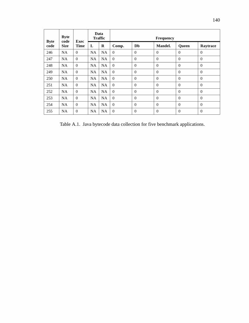
140
246 NA 0 NA NA 0 0 0 0 0
247 NA 0 NA NA 0 0 0 0 0
248 NA 0 NA NA 0 0 0 0 0
249 NA 0 NA NA 0 0 0 0 0
250 NA 0 NA NA 0 0 0 0 0
251 NA 0 NA NA 0 0 0 0 0
252 NA 0 NA NA 0 0 0 0 0
253 NA 0 NA NA 0 0 0 0 0
254 NA 0 NA NA 0 0 0 0 0
255 NA 0 NA NA 0 0 0 0 0
Bytecode
Bytecode Size
Exec Time
Data Traffic Frequency
L R Comp. Db Mandel. Queen Raytrace
Table A.1. Java bytecode data collection for five benchmark applications.
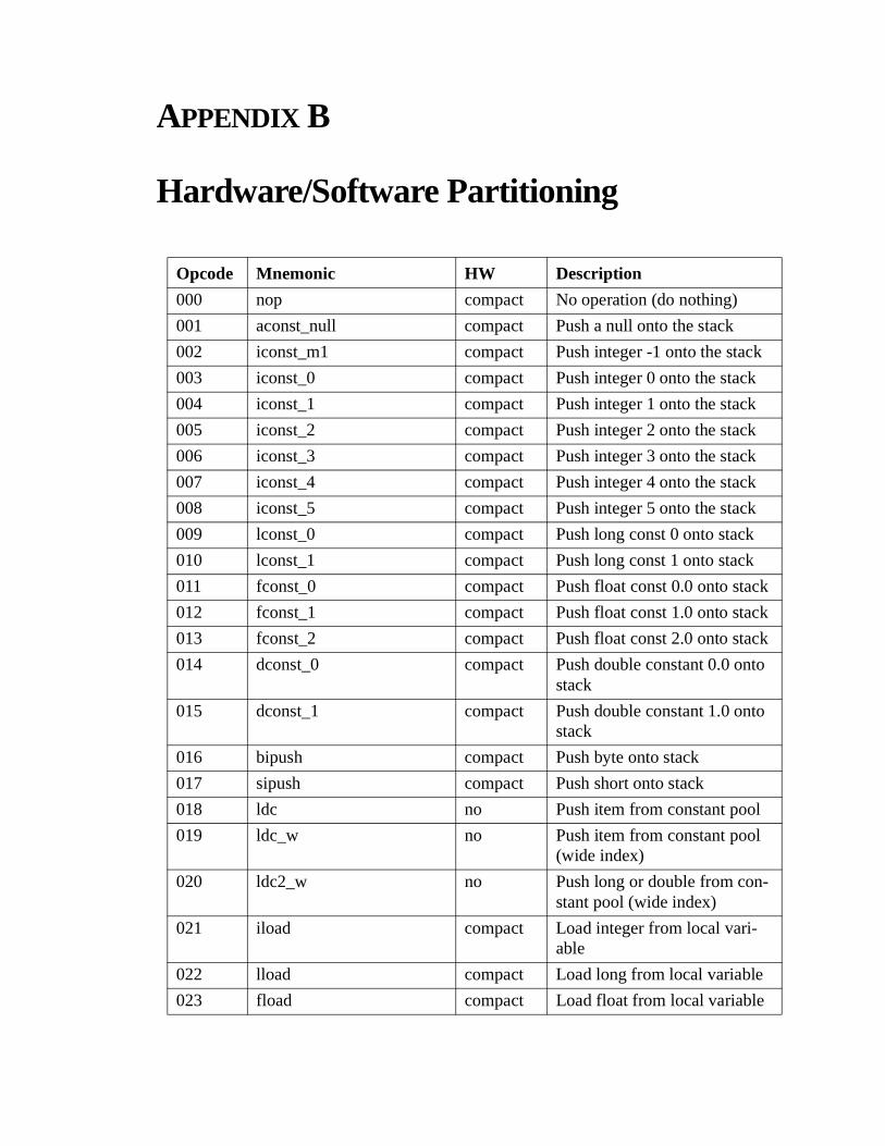
APPENDIX B
Hardware/Software Partitioning Appendix B
Opcode Mnemonic HW Description
000 nop compact No operation (do nothing)
001 aconst_null compact Push a null onto the stack
002 iconst_m1 compact Push integer -1 onto the stack
003 iconst_0 compact Push integer 0 onto the stack
004 iconst_1 compact Push integer 1 onto the stack
005 iconst_2 compact Push integer 2 onto the stack
006 iconst_3 compact Push integer 3 onto the stack
007 iconst_4 compact Push integer 4 onto the stack
008 iconst_5 compact Push integer 5 onto the stack
009 lconst_0 compact Push long const 0 onto stack
010 lconst_1 compact Push long const 1 onto stack
011 fconst_0 compact Push float const 0.0 onto stack
012 fconst_1 compact Push float const 1.0 onto stack
013 fconst_2 compact Push float const 2.0 onto stack
014 dconst_0 compact Push double constant 0.0 onto stack
015 dconst_1 compact Push double constant 1.0 onto stack
016 bipush compact Push byte onto stack
017 sipush compact Push short onto stack
018 ldc no Push item from constant pool
019 ldc_w no Push item from constant pool (wide index)
020 ldc2_w no Push long or double from con-stant pool (wide index)
021 iload compact Load integer from local vari-able
022 lload compact Load long from local variable
023 fload compact Load float from local variable

142
024 dload compact Load double from local vari-able
025 aload compact Load reference from local vari-able
026 iload_0 compact Load integer from local vari-able (index 0)
027 iload_1 compact Load integer from local vari-able (index 1)
028 iload_2 compact Load integer from local vari-able (index 2)
029 iload_3 compact Load integer from local vari-able (index 3)
030 lload_0 compact Load long from local variable (index 0)
031 lload_1 compact Load long from local variable (index 1)
032 lload_2 compact Load long from local variable (index 2)
033 lload_3 compact Load long from local variable (index 3)
034 fload_0 compact Load float from local variable (index 0)
035 fload_1 compact Load float from local variable (index 1)
036 fload_2 compact Load float from local variable (index 2)
037 fload_3 compact Load float from local variable (index 3)
038 dload_0 compact Load double from local vari-able (index 0)
039 dload_1 compact Load double from local vari-able (index 1)
040 dload_2 compact Load double from local vari-able (index 2)
041 dload_3 compact Load double from local vari-able (index 3)
042 aload_0 compact Load reference from local vari-able (index 0)
Opcode Mnemonic HW Description

143
043 aload_1 compact Load reference from local vari-able (index 1)
044 aload_2 compact Load reference from local vari-able (index 2)
045 aload_3 compact Load reference from local vari-able (index 3)
046 iaload memory Load integer from array
047 laload memory Load long from array
048 faload memory Load float from array
049 daload memory Load double from array
050 aaload memory Load reference from array
051 baload memory Load byte or boolean from array
052 caload memory Load character from array
053 saload memory Load short from array
054 istore compact Store integer into local variable
055 lstore compact Store long into local variable
056 fstore compact Store float into local variable
057 dstore compact Store double into local variable
058 astore compact Store reference into local vari-able
059 istore_0 compact Store integer into local variable (index 0)
060 istore_1 compact Store integer into local variable (index 1)
061 istore_2 compact Store integer into local variable (index 2)
062 istore_3 compact Store integer into local variable (index 3)
063 lstore_0 compact Store long into local variable (index 0)
064 lstore_1 compact Store long into local variable (index 1)
065 lstore_2 compact Store long into local variable (index 2)
066 lstore_3 compact Store long into local variable (index 3)
Opcode Mnemonic HW Description
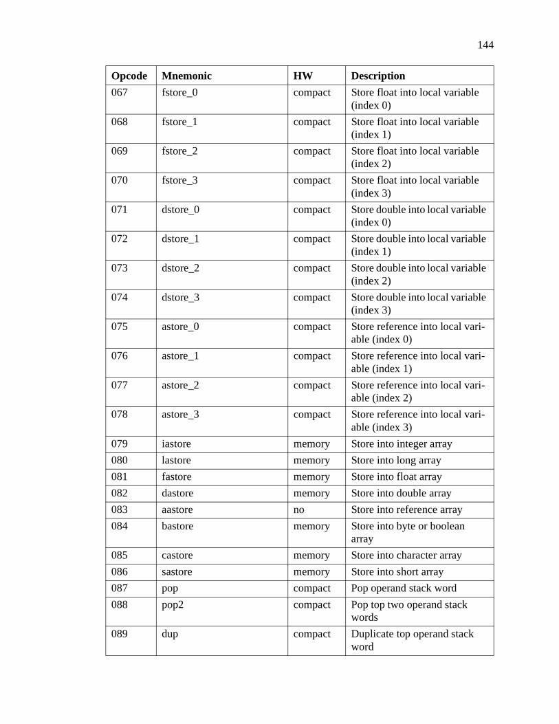
144
067 fstore_0 compact Store float into local variable (index 0)
068 fstore_1 compact Store float into local variable (index 1)
069 fstore_2 compact Store float into local variable (index 2)
070 fstore_3 compact Store float into local variable (index 3)
071 dstore_0 compact Store double into local variable (index 0)
072 dstore_1 compact Store double into local variable (index 1)
073 dstore_2 compact Store double into local variable (index 2)
074 dstore_3 compact Store double into local variable (index 3)
075 astore_0 compact Store reference into local vari-able (index 0)
076 astore_1 compact Store reference into local vari-able (index 1)
077 astore_2 compact Store reference into local vari-able (index 2)
078 astore_3 compact Store reference into local vari-able (index 3)
079 iastore memory Store into integer array
080 lastore memory Store into long array
081 fastore memory Store into float array
082 dastore memory Store into double array
083 aastore no Store into reference array
084 bastore memory Store into byte or boolean array
085 castore memory Store into character array
086 sastore memory Store into short array
087 pop compact Pop operand stack word
088 pop2 compact Pop top two operand stack words
089 dup compact Duplicate top operand stack word
Opcode Mnemonic HW Description

145
090 dup_x1 compact Duplicate top operand stack word and put two down
091 dup_x2 compact Duplicate top operand stack word and put three down
092 dup2 compact Duplicate two top operand stack words
093 dup2_x1 compact Duplicate top two operand stack words, put three down
094 dup2_x2 compact Duplicate top two operand stack words and put four down
095 swap compact Swap top two operand stack words
096 iadd compact Add two integers from stack and push result onto stack
097 ladd compact Add two longs from stack and push result onto stack
098 fadd compact Add two floats from stack and push result on stack
099 dadd compact Add two doubles from stack and push result on stack.
100 isub compact Subtract integer
101 lsub compact Subtract long
102 fsub compact Subtract float
103 dsub compact Subtract double
104 imul compact Multiple integer
105 lmul no Multiply long
106 fmul compact Multiply float
107 dmul compact Multiply double
108 idiv compact Integer divide
109 ldiv no Long divide
110 fdiv compact Float divide
111 ddiv compact Divide double
112 irem compact Remainder integer
113 lrem no Remainder long
114 frem compact Remainder float
115 drem compact Remainder double
116 ineg compact Negate integer
Opcode Mnemonic HW Description

146
117 lneg compact Negate long
118 fneg compact Negate float
119 dneg compact Negate double
120 ishl compact Shift integer left
121 lshl compact Shift left long
122 ishr compact Shift integer right
123 lshr compact Shift long right
124 iushr compact Logical shift right integer
125 lushr compact Logical shift right long
126 iand compact Boolean AND integer
127 land compact Boolean AND long
128 ior compact Boolean OR integer
129 lor compact Boolean OR long
130 ixor compact Boolean XOR integer
131 lxor compact Boolean XOR long
132 iinc compact Increment local variable by constant
133 i2l compact Convert integer to long
134 i2f compact Convert integer to float
135 i2d compact Convert integer to double
136 l2i compact Convert long to integer
137 l2f compact Convert long to float
138 l2d compact Convert long to double
139 f2i compact Convert float to integer
140 f2l compact Convert float to long
141 f2d compact Convert float to double
142 d2i compact Convert double to integer
143 d2l compact Convert double to long
144 d2f compact Convert double to float
145 i2b compact Convert integer to byte
146 i2c compact Convert integer to character
147 i2s compact Convert integer to short
148 lcmp compact Compare long
149 fcmpl compact Compare float for less than
150 fcmpg compact Compare float for greater than
Opcode Mnemonic HW Description

147
151 dcmpl compact Compare double for less than
152 dcmpg compact Compare double for greater than
153 ifeq compact Branch if integer comparison with zero succeeds
154 ifne compact Branch if integer comparison with zero succeeds
155 iflt compact Branch if integer comparison with zero succeeds
156 ifge compact Branch if integer comparison with zero succeeds
157 ifgt compact Branch if integer comparison with zero succeeds
158 ifle compact Branch if integer comparison with zero succeeds
159 if_icmpeq compact Branch if integer comparison is equal
160 if_icmpne compact Branch if integer comparison is not equal
161 if_icmplt compact Branch if integer comparison is less than
162 if_icmpge compact Branch if integer comparison is greater than or equal
163 if_icmpgt compact Branch if integer comparison is greater then
164 if_icmple compact Branch if integer comparison is less than or equal
165 if_acmpeq compact Branch if reference compari-son equal
166 if_acmpne compact Branch if reference compari-son not equal
167 goto compact Branch always
168 jsr compact Jump subroutine
169 ret compact Return from subroutine
170 tableswitch no Access jump table by index and jump
171 lookupswitch no Access jump table by key match and jump
Opcode Mnemonic HW Description

148
172 ireturn no Return integer from method
173 lreturn no Return long from method
174 freturn no Return float from method
175 dreturn no Return double from method
176 areturn no Return reference from method
177 return no Return void from method
178 getstatic no Get static field from class
179 putstatic no Set static field in class
180 getfield no Fetch field from object
181 putfield no Set field in object
182 invokevirtual no Invoke instance method; dis-patch based on class
183 invokespecial no Invoke instance method
184 invokestatic no Invoke a class (static) method
185 invokeinterface no Invoke interface method
186 UNUSED NA
187 new no Create a new object
188 newarray no Create a new array
189 anewarray no Create new array of reference
190 arraylength memory Get length of array
191 athrow no Throw exception or error
192 checkcast no Check whether object is of given type
193 instanceof no Determine if object is of given type
194 monitorenter no Enter monitor for object
195 monitorexit no Exit monitor for object
196 wide no Extend local variable index by additional bytes
197 multinewarray no Create new multidimensional array
198 ifnull compact Branch if reference is null
199 ifnonnull compact Branch if reference is not null
200 goto_w compact Branch always (wide index)
201 jsr_w compact Jump subroutine (wide index)
Opcode Mnemonic HW Description

149
202 breakpoint no RESERVED FOR DEBUG-GERS
203 ldc_quick quick Push item from constant pool
204 ldc_w_quick quick Push item from constant pool (wide index)
205 ldc2_w_quick quick Push long or double from con-stant pool (wide index)
206 getfield_quick quick Fetch field from object
207 putfield_quick quick Set field in object
208 getfield2_quick quick Fetch long or double field from object
209 putfield2_quick quick Set long or double field in object
210 getstatic_quick quick Get static field from class
211 putstatic_quick quick Set static field in class
212 getstatic2_quick quick Get static field from class
213 putstatic2_quick quick Set static field in class
214 invokevirtual_quick no Invoke instance method
215 invokenonvirtual_quick no Invoke an instance initializa-tion method
216 invokesuper_quick no Invoke a super class method
217 invokestatic_quick no Invoke a class (static) method
218 invokeinterface_quick no Invoke interface method
219 invokevirtualobject_quick no Invoke instance method of class Java.lang.Object
220 UNUSED NA
221 new_quick no Create a new object
222 anewarray_quick no Create new array of reference
223 multianewarray_quick no Create new multidimensional array
224 checkcast_quick no Check whether object is of given type
225 instanceof_quick no Determine if object is of given type
226 invokevirtual_quick_w no Invoke instance method (wide index)
Opcode Mnemonic HW Description

150
227 getfield_quick_w quick Fetch field from object (wide index)
228 putfield_quick_w quick Set field from object (wide index)
229 UNUSED NA
230 UNUSED NA
231 UNUSED NA
232 UNUSED NA
233 UNUSED NA
234 UNUSED NA
235 UNUSED NA
236 UNUSED NA
237 UNUSED NA
238 UNUSED NA
239 UNUSED NA
240 UNUSED NA
241 UNUSED NA
242 UNUSED NA
243 UNUSED NA
244 UNUSED NA
245 UNUSED NA
246 UNUSED NA
247 UNUSED NA
248 UNUSED NA
249 UNUSED NA
250 UNUSED NA
251 UNUSED NA
252 UNUSED NA
253 UNUSED NA
254 consw compact Context switch to software
255 conhw compact Context switch to hardware
Opcode Mnemonic HW Description
Table B.1. Specification of Java virtual machine instruction set between partitioning schemes.

APPENDIX C
Context Switching Benchmark Results Appendix C
C.1 Compress Benchmark
1
10
100
1000
10000
1 3 5 7 9 11 13 15 17 19 21 23 25 27 29
Block Size
Nu
mb
er o
f B
lock
s
Pessimistic Optimistic Pushy
Figure C.1 Number of blocks for each algorithm in Compress benchmark.

152
0
20
40
60
80
100
120
1 3 5 7 9 11 13 15 17 19 21 23 25 27 29
Block Size
% H
ard
war
e In
stru
ctio
ns
Pessimistic Optimistic Pushy
Figure C.2 Percentage of hardware instructions for each algorithm in Compress benchmark.

153
C.2 Db Benchmark
1
10
100
1000
10000
1 3 5 7 9 11 13 15 17 19 21 23 25 27 29
Block Size
Nu
mb
er o
f B
lock
s
Pessimistic Optimistic Pushy
Figure C.1 Number of blocks for each algorithm in Db benchmark.
0
20
40
60
80
100
120
1 3 5 7 9 11 13 15 17 19 21 23 25 27 29
Block Size
% H
ard
war
e In
stru
ctio
ns
Pessimistic Optimistic Pushy
Figure C.2 Percentage of hardware instructions for each algorithm in Db benchmark.

154
C.3 Mandel Benchmark
1
10
100
1000
10000
1 3 5 7 9 11 13 15 17 19 21 23 25 27 29
Block Size
Nu
mb
er o
f B
lock
s
Pessimistic Optimistic Pushy
Figure C.1 Number of blocks for each algorithm in Mandel benchmark.
0
20
40
60
80
100
120
1 3 5 7 9 11 13 15 17 19 21 23 25 27 29
Block Size
% H
ard
war
e In
stru
ctio
ns
Pessimistic Optimistic Pushy
Figure C.2 Percentage of hardware instructions for each algorithm in Mandel benchmark.

155
C.4 Queen Benchmark
1
10
100
1000
10000
1 3 5 7 9 11 13 15 17 19 21 23 25 27 29
Block Size
Nu
mb
er o
f B
lock
s
Pessimistic Optimistic Pushy
Figure C.1 Number of blocks for each algorithm in Queen benchmark.
0
20
40
60
80
100
120
1 3 5 7 9 11 13 15 17 19 21 23 25 27 29
Block Size
% H
ard
war
e In
stru
ctio
ns
Pessimistic Optimistic Pushy
Figure C.2 Percentage of hardware instructions for each algorithm in Queen benchmark.

156
C.5 Raytrace Benchmark
1
10
100
1000
10000
100000
1 3 5 7 9 11 13 15 17 19 21 23 25 27 29
Block Size
Nu
mb
er o
f B
lock
s
Pessimistic Optimistic Pushy
Figure C.1 Number of blocks for each algorithm in Raytrace benchmark.
0
20
40
60
80
100
120
1 3 5 7 9 11 13 15 17 19 21 23 25 27 29
Block Size
% H
ard
war
e In
stru
ctio
ns
Pessimistic Optimistic Pushy
Figure C.2 Percentage of hardware instructions for each algorithm in Raytrace benchmark.
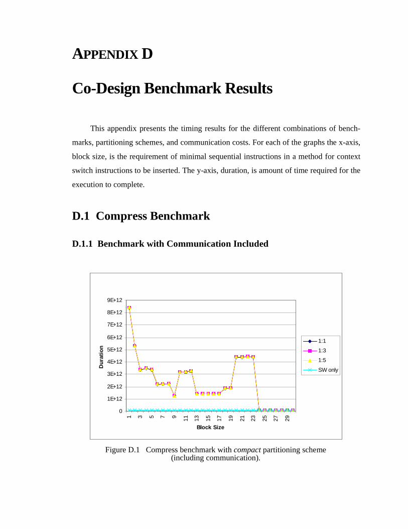
APPENDIX D
Co-Design Benchmark Results Appendix D
This appendix presents the timing results for the different combinations of bench-
marks, partitioning schemes, and communication costs. For each of the graphs the x-axis,
block size, is the requirement of minimal sequential instructions in a method for context
switch instructions to be inserted. The y-axis, duration, is amount of time required for the
execution to complete.
D.1 Compress Benchmark
D.1.1 Benchmark with Communication Included
0
1E+12
2E+12
3E+12
4E+12
5E+12
6E+12
7E+12
8E+12
9E+12
1 3 5 7 9 11 13 15 17 19 21 23 25 27 29
Block Size
Du
rati
on
1:1
1:3
1:5
SW only
Figure D.1 Compress benchmark with compact partitioning scheme (including communication).
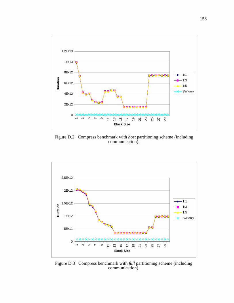
158
0
2E+12
4E+12
6E+12
8E+12
1E+13
1.2E+13
1 3 5 7 9 11 13 15 17 19 21 23 25 27 29
Block Size
Du
rati
on
1:1
1:3
1:5
SW only
Figure D.2 Compress benchmark with host partitioning scheme (including communication).
0
5E+11
1E+12
1.5E+12
2E+12
2.5E+12
1 3 5 7 9 11 13 15 17 19 21 23 25 27 29
Block Size
Du
rati
on
1:1
1:3
1:5
SW only
Figure D.3 Compress benchmark with full partitioning scheme (including communication).

159
D.1.2 Benchmark with Communication Excluded
0
1E+10
2E+10
3E+10
4E+10
5E+10
6E+10
7E+10
8E+10
9E+10
1E+11
1 3 5 7 9 11 13 15 17 19 21 23 25 27 29
Block Size
Du
rati
on
1:1
1:3
1:5
SW only
Figure D.4 Compress benchmark with compact partitioning scheme (excluding communication).
0
1E+10
2E+10
3E+10
4E+10
5E+10
6E+10
7E+10
8E+10
9E+10
1E+11
1 3 5 7 9 11 13 15 17 19 21 23 25 27 29
Block Size
Du
rati
on
1:1
1:3
1:5
SW only
Figure D.5 Compress benchmark with host partitioning scheme (excluding communication).

160
0
1E+10
2E+10
3E+10
4E+10
5E+10
6E+10
7E+10
8E+10
9E+10
1E+11
1 3 5 7 9 11 13 15 17 19 21 23 25 27 29
Block Size
Du
rati
on
1:1
1:3
1:5
SW only
Figure D.6 Compress benchmark with full partitioning scheme (excluding communication).
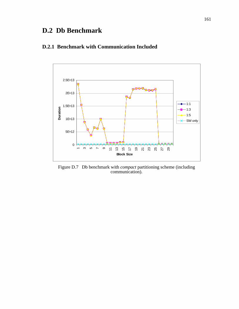
161
D.2 Db Benchmark
D.2.1 Benchmark with Communication Included
0
5E+12
1E+13
1.5E+13
2E+13
2.5E+131 3 5 7 9 11 13 15 17 19 21 23 25 27 29
Block Size
Du
rati
on
1:1
1:3
1:5
SW only
Figure D.7 Db benchmark with compact partitioning scheme (including communication).

162
0
5E+12
1E+13
2E+13
2E+13
3E+13
3E+13
1 3 5 7 9 11 13 15 17 19 21 23 25 27 29
Block Size
Du
rati
on
1:1
1:3
1:5
SW only
Figure D.8 Db benchmark with host partitioning scheme (including communication).
0
1E+12
2E+12
3E+12
4E+12
5E+12
6E+12
7E+12
8E+12
1 3 5 7 9 11 13 15 17 19 21 23 25 27 29
Block Size
Du
rati
on
1:1
1:3
1:5
SW only
Figure D.9 Db benchmark with full partitioning scheme (including communication).
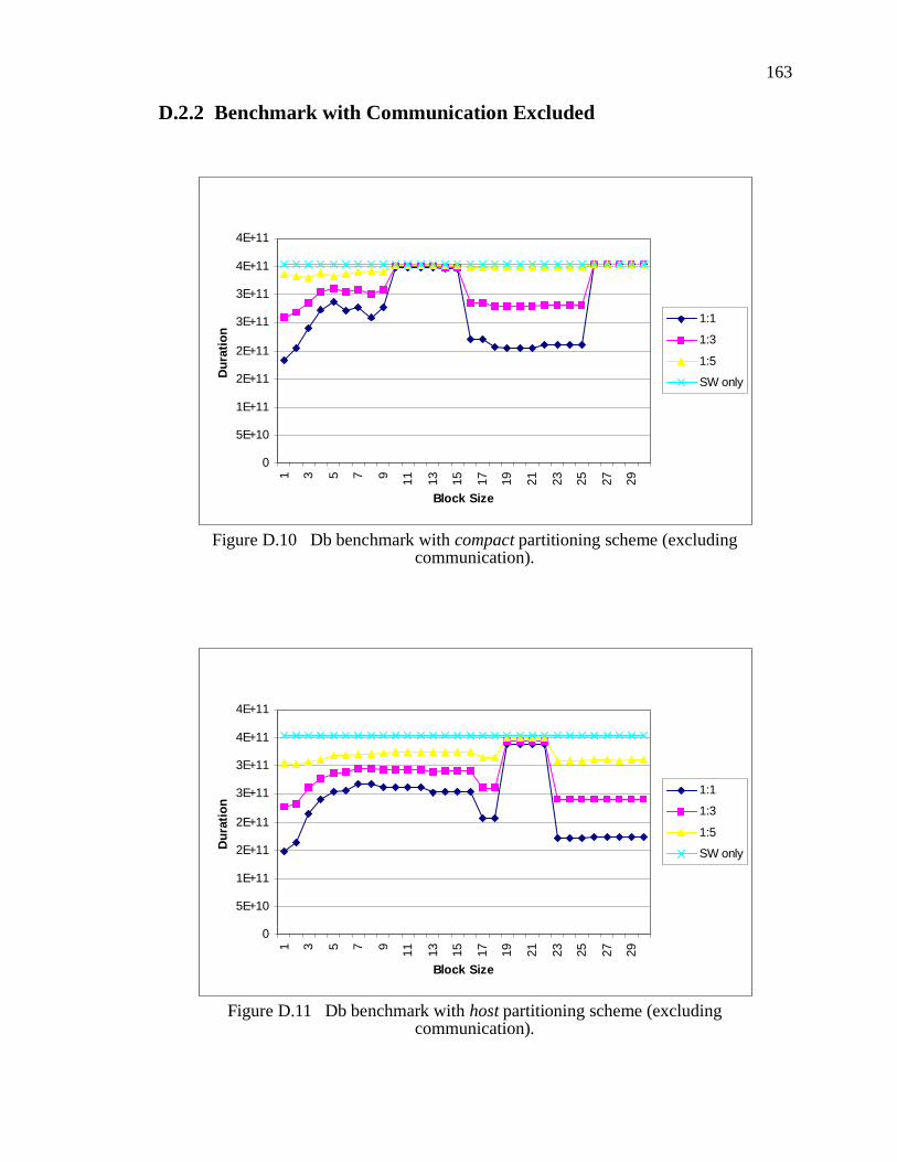
163
D.2.2 Benchmark with Communication Excluded
0
5E+10
1E+11
2E+11
2E+11
3E+11
3E+11
4E+11
4E+11
1 3 5 7 9 11 13 15 17 19 21 23 25 27 29
Block Size
Du
rati
on
1:1
1:3
1:5
SW only
Figure D.10 Db benchmark with compact partitioning scheme (excluding communication).
0
5E+10
1E+11
2E+11
2E+11
3E+11
3E+11
4E+11
4E+11
1 3 5 7 9 11 13 15 17 19 21 23 25 27 29
Block Size
Du
rati
on
1:1
1:3
1:5
SW only
Figure D.11 Db benchmark with host partitioning scheme (excluding communication).

164
0
5E+10
1E+11
2E+11
2E+11
3E+11
3E+11
4E+11
4E+11
1 3 5 7 9 11 13 15 17 19 21 23 25 27 29
Block Size
Du
rati
on
1:1
1:3
1:5
SW only
Figure D.12 Db benchmark with full partitioning scheme (excluding communication).
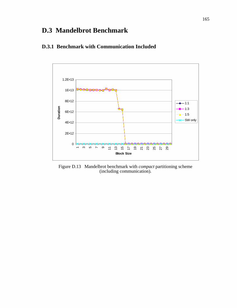
165
D.3 Mandelbrot Benchmark
D.3.1 Benchmark with Communication Included
0
2E+12
4E+12
6E+12
8E+12
1E+13
1.2E+131 3 5 7 9 11 13 15 17 19 21 23 25 27 29
Block Size
Du
rati
on
1:1
1:3
1:5
SW only
Figure D.13 Mandelbrot benchmark with compact partitioning scheme (including communication).

166
0
2E+12
4E+12
6E+12
8E+12
1E+13
1.2E+13
1 3 5 7 9 11 13 15 17 19 21 23 25 27 29
Block Size
Du
rati
on
1:1
1:3
1:5
SW only
Figure D.14 Mandelbrot benchmark with host partitioning scheme (including communication).
0
10000000000
20000000000
30000000000
40000000000
50000000000
60000000000
70000000000
80000000000
90000000000
1 4 7 10 13 16 19 22 25 28
Block Size
Du
rati
on
1:1
1:3
1:5
SW only
Figure D.15 Mandelbrot benchmark with full partitioning scheme (including communication).

167
D.3.2 Benchmark with Communication Excluded
0
1E+10
2E+10
3E+10
4E+10
5E+10
6E+10
7E+10
8E+10
9E+10
1E+11
1 3 5 7 9 11 13 15 17 19 21 23 25 27 29
Block Size
Du
rati
on
1:1
1:3
1:5
SW only
Figure D.16 Mandelbrot benchmark with compact partitioning scheme (excluding communication).

168
0
1E+10
2E+10
3E+10
4E+10
5E+10
6E+10
7E+10
8E+10
9E+10
1E+11
1 3 5 7 9 11 13 15 17 19 21 23 25 27 29
Block Size
Du
rati
on
1:1
1:3
1:5
SW only
Figure D.17 Mandelbrot benchmark with host partitioning scheme (excluding communication).
0
10000000000
20000000000
30000000000
40000000000
50000000000
60000000000
70000000000
80000000000
90000000000
1 4 7 10 13 16 19 22 25 28
Block Size
Du
rati
on
1:1
1:3
1:5
SW only
Figure D.18 Mandelbrot benchmark with full partitioning scheme (excluding communication).

169
D.4 Queen Benchmark
D.4.1 Benchmark with Communication Included
0
1E+11
2E+11
3E+11
4E+11
5E+11
6E+11
7E+111 3 5 7 9 11 13 15 17 19 21 23 25 27 29
Block Size
Du
rati
on
1:1
1:3
1:5
SW only
Figure D.19 Queen benchmark with compact partitioning scheme (including communication).

170
0
1E+11
2E+11
3E+11
4E+11
5E+11
6E+11
1 3 5 7 9 11 13 15 17 19 21 23 25 27 29
Block Size
Du
rati
on
1:1
1:3
1:5
SW only
Figure D.20 Queen benchmark with host partitioning scheme (including communication).
0
1000000000
2000000000
3000000000
4000000000
5000000000
6000000000
7000000000
1 4 7 10 13 16 19 22 25 28
Block Size
Du
rati
on
1:1
1:3
1:5
SW only
Figure D.21 Queen benchmark with full partitioning scheme (including communication).

171
D.4.2 Benchmark with Communication Excluded
0
500000000
1000000000
1500000000
2000000000
2500000000
3000000000
3500000000
4000000000
4500000000
1 4 7 10 13 16 19 22 25 28
Block Size
Du
rati
on
1:1
1:3
1:5
SW only
Figure D.22 Queen benchmark with compact partitioning scheme (excluding communication).

172
0
500000000
1000000000
1500000000
2000000000
2500000000
3000000000
3500000000
4000000000
1 4 7 10 13 16 19 22 25 28
Block Size
Du
rati
on
1:1
1:3
1:5
SW only
Figure D.23 Queen benchmark with host partitioning scheme (excluding communication).
0
500000000
1000000000
1500000000
2000000000
2500000000
3000000000
3500000000
4000000000
1 4 7 10 13 16 19 22 25 28
Block Size
Du
rati
on
1:1
1:3
1:5
SW only
Figure D.24 Queen benchmark with full partitioning scheme (excluding communication).

173
D.5 Raytrace Benchmark
D.5.1 Benchmark with Communication Included
0
5E+12
1E+13
1.5E+13
2E+13
2.5E+131 3 5 7 9 11 13 15 17 19 21 23 25 27 29
Block Size
Du
rati
on
1:1
1:3
1:5
SW only
Figure D.25 Raytrace benchmark with compact partitioning scheme (including communication).

174
0
5E+12
1E+13
1.5E+13
2E+13
2.5E+13
1 3 5 7 9 11 13 15 17 19 21 23 25 27 29
Block Size
Du
rati
on
1:1
1:3
1:5
SW only
Figure D.26 Raytrace benchmark with host partitioning scheme (including communication).
0
5E+12
1E+13
1.5E+13
2E+13
2.5E+13
1 3 5 7 9 11 13 15 17 19 21 23 25 27 29
Block Size
Du
rati
on
1:1
1:3
1:5
SW only
Figure D.27 Raytrace benchmark with full partitioning scheme (including communication).
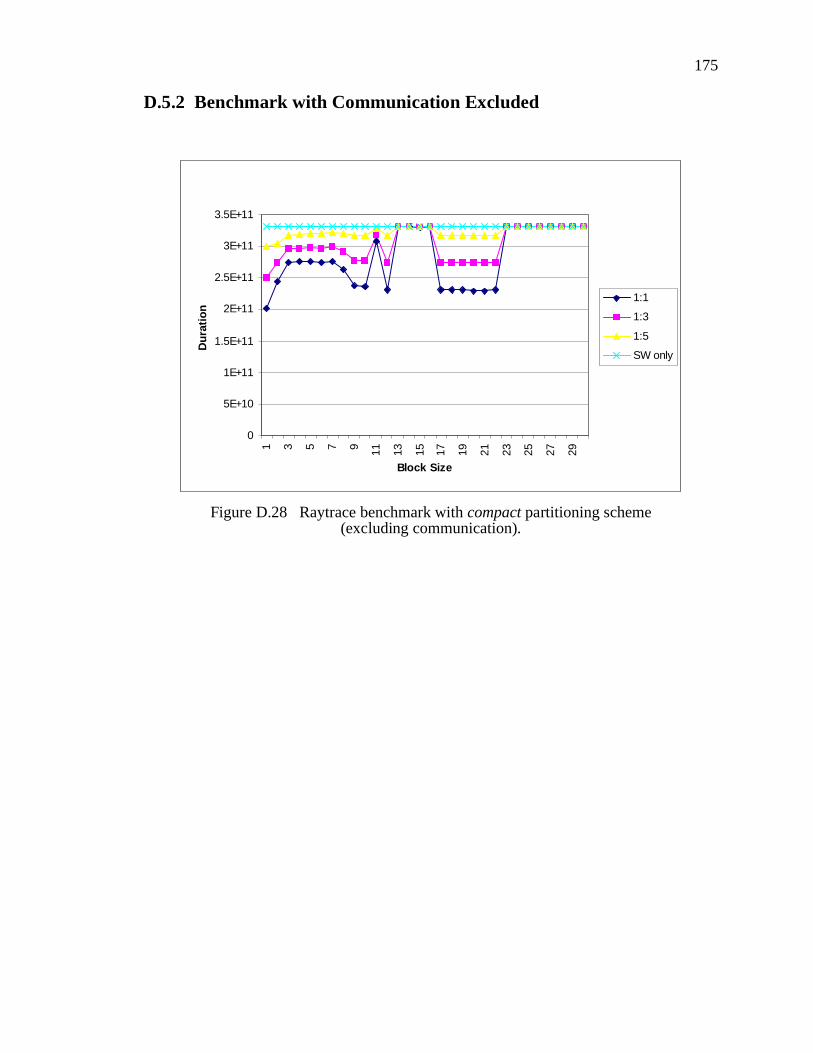
175
D.5.2 Benchmark with Communication Excluded
0
5E+10
1E+11
1.5E+11
2E+11
2.5E+11
3E+11
3.5E+11
1 3 5 7 9 11 13 15 17 19 21 23 25 27 29
Block Size
Du
rati
on
1:1
1:3
1:5
SW only
Figure D.28 Raytrace benchmark with compact partitioning scheme (excluding communication).

176
0
5E+10
1E+11
1.5E+11
2E+11
2.5E+11
3E+11
3.5E+11
1 3 5 7 9 11 13 15 17 19 21 23 25 27 29
Block Size
Du
rati
on
1:1
1:3
1:5
SW only
Figure D.29 Raytrace benchmark with host partitioning scheme (excluding communication).
0
5E+10
1E+11
1.5E+11
2E+11
2.5E+11
3E+11
3.5E+11
1 3 5 7 9 11 13 15 17 19 21 23 25 27 29
Block Size
Du
rati
on
1:1
1:3
1:5
SW only
Figure D.30 Raytrace benchmark with full partitioning scheme (excluding communication).

177177177177177177
Bibliography
[1] AMD. 3DNow! Technology Manual. http://www.amd.com/us-en/assets/content_type/white_papers_and_tech_docs/21928.pdf, July, 2002.
[2] Aoki, Takashi, and Eto, Takeshi. On the Software Virtual Machine forthe Real Hardware Stack Machine. USENIX Java Virtual MachineResearch and Technology Symposium, April, 2001.
[3] Arm Ltd. Jazelle - ARM Architecture Extensions for Java Applications.http://www.arm.com/armtech/jazelle, Arm Ltd., September 2001.
[4] Arm Ltd. ARM - Jazelle Technology, http://www.arm.com/armtech/jazelle. Arm Ltd., September 2001.
[5] Arnold, Ken. and Gosling, James. The Java Programming Language(2nd edition). Addison-Wesley, 1997.
[6] Atherton, Robert J. Moving Java to the Factory. IEEE Spectrum, pp. 18- 23, December 1998.
[7] Ashenden, Peter J. The Designer’s Guide to VHDL. Morgan KaufmannPublishers, 1996.
[8] Aurora VLSI Inc. DeCaf - Summary, http://www.auroravlsi.com/web-site/DeCaf_summary.html. Aurora VLSI Inc., September 2001.
[9] Aurora VLSI Inc. Espresso - Datasheet, http://www.auroravlsi.com/website/Espresso_datasheet.html, Aurora VLSI Inc., September 2001.
[10] Aurora VLSI Inc. Espresso - Summary, http://www.auroravlsi.com/website/Espresso_summary.html, Aurora VLSI Inc., September 2001.
[11] Awalt, R. K. Making the ASIC/FPGA Decision, Integrated SystemDesign Magazine, July 1999.
[12] Bass, M. J. and Christensen, C. M. The Future of the MicroprocessorBusiness, IEEE Spectrum, pp. 34-39, April 2002.
[13] Benveniste, A. and Bery, G. The Synchronous Approach to Reactive

178178178178178178
and Real-Time Systems, IEEE Proceedings, Vol. 79, No. 9., pp. 1270 -1282, September 1991.
[14] Berge, J. M., Levia, O. and Rouillard, J. (eds). Hardware/Software Co-Design and Co-Verification, Kluwer Academic Publishers, 1997.
[15] Bingham, J. and Serra, M. Solving Hamiltonian Cycle on FPGA Tech-nology via Instance to Circuit Mappings, Workshop on Engineering ofReconfigurable Hardware/Software Objects, PDPTA, June 2000.
[16] Brown, Stephen D., Francis, Robert J., Rose, Jonathan, and Vranesic,Zvonko G. Field-Programmable Gate Arrays, Kluwer Academic Pub-lishers, 1992.
[17] Burton, Kevin. .NET Common Language Runtime Unleashed, SamsPublishers, March 2002.
[18] Cardoso, J. M. P. and Neto, H. C. Macro-Based Hardware Compilationof Java Bytecodes into a Dynamic Reconfigurable Computing System.IEEE Symposium on Field-Programmable Custom ComputingMachines, April 1999.
[19] Case, Brian. Implementing the Java Virtual Machine, MicroprocessorReport, pp. 12 - 17, March 25, 1996.
[20] Case, Brian. Java Virtual Machine Should Stay Virtual, Microproces-sor Report, pp. 14 - 15, April 15, 1996.
[21] Case, Brian. Java Performance Advancing Rapidly, MicroprocessorReport, pp. 17 - 19, May 27, 1996.
[22] Chu, Yaohan (ed). High-Level Language Computer Architecture, Aca-demic Press Inc., 1975.
[23] Compton, K., and Hauck, S. Reconfigurable Computing: A Survey ofSystems and Software, ACM Computing Surveys, Vol. 34, No. 2, pp.171-210, June 2002.
[24] Cornell, G. and Horstmann, C. S. Core Java. SunSoft Press, 1996.
[25] De Micheli, G. and Sami, M. (eds.) Hardware/Software Co-Design.Kluwer Academic Publishers, pp. 1-28, 1996.
[26] De Micheli, G., Ernst, R. and Wolf, W. Readings in Hardware/SoftwareCo-Design. Morgan Kaufmann Publishers, 2002.
179179179179179179
[27] Dey, S. et al. Using a Soft Core in a SoC Design: Experiences withpicoJava. IEEE Design & Test, pp. 60-71, July-Sept 2000.
[28] Dorf, R. C. Field Programmable Gate Arrays: Reconfigurable Logicfor Rapid Prototyping and Implementation of Digital Systems. Wiley &Sons Inc., 1995.
[29] El-Kharashi, M. W. and ElGuibaly, F. Java Microprocessors: ComputerArchitecture Implications. IEEE Pacific Rim Conference on Communi-cations, Computers and Signal Processing (PACRIM 1997), pp. 277-280, August 1997.
[30] El-Kharashi, M. W., ElGuibaly, F., and Li K.F. A New Methodology forStack Operations Folding for Java Microprocessors. High PerformanceComputing Systems and Applications, chapter 11, pp. 149 - 160, Klu-wer Academic Publishers, 2000.
[31] El-Kharashi, M. W., ElGuibaly, F., and Li K.F. A Novel Approach forStack Operations Folding for Java Processors. IEEE Computer SocietyTechnical Committee on Computer Architecture Newsletter, pp. 104 -107, September 2000.
[32] El-Kharashi, M. W., ElGuibaly, F., and Li K.F. An Operand Extraction-Based Stack Folding Algorithm for Java Processors. International Con-ference on Computer Design, pp. 22 - 26, September 2000.
[33] El-Kharashi, M. W., ElGuibaly, F., and Li K.F. Quantitative Analysisfor Java Microprocessor Architectural Requirements: Instruction SetDesign. International Conference on Computer Design, pp. 50 - 54,October 1999.
[34] El-Kharashi, M. W., ElGuibaly, F., and Li K.F. A Quantitative Study forJava Microprocessor Architectural Requirements. Part I: InstructionSet Design. Microprocessors and Microsystems, pp. 225 - 236, Septem-ber 2000.
[35] El-Kharashi, M. W., ElGuibaly, F., and Li K.F. A Quantitative Study forJava Microprocessor Architectural Requirements. Part II: High-LevelLanguage Support. Microprocessors and Microsystems, pp. 237 - 250,September 2000.
[36] Engel, Joshua. Programming for the Java Virtual Machine, Addison-Wesley, 1999.
[37] Gajski, D., Vahid, F., Narayan, S., and Gong, J. Specification and

180180180180180180
Design of Embedded Systems. Prentice-Hall Inc., 1994.
[38] Gajski, D., Zhu, J., Domer, R., Gerstlauer, A., and Zhao, S. SpecC:Specification Language and Methodology. Kluwer Academic Publish-ers, 2000.
[39] Goldberg, A. and Robson, D. Smalltalk-80: The Language and itsImplementation. Addison Wesley, 1983.
[40] Gosling, J. The Feel of Java. IEEE Computer, pp. 53-57, June 1997.
[41] Gu, W., Burns, N. A., Collins, M. T., and Wong, W. Y. P. The Evolutionof a High-Performing Java Virtual Machine. IBM systems Journal, vol39, no 1, pp. 135 - 150, 2000.
[42] Gupta, Rajesh Kumar. Co-Synthesis of Hardware and Software for Dig-ital Embedded Systems. Kluwer Academic Publishers, 1995.
[43] Halfhill, T. R. How to Soup up Java (Part I), BYTE, pp. 60 - 74, May1998.
[44] Harel, D., Pneuli, A., Schmidt, J., and Sherman, R. Statecharts: AVisual Formalism for Complex Systems, Science of Computer Pro-gramming, No. 8, pp. 231 - 274, 1987.
[45] Hauck, S. The Future of Reconfigurable Systems. Keynote Address, 5thCanadian Conference on Field Programmable Devices, Montreal, June1998.
[46] Henkel, Joerg., and Hu, Xiaobo (general co-chairs). Tenth Interna-tional Symposium on Hardware/Software Codesign. ACM Press, 2002.
[47] http://ptolemy.eecs.berkeley.edu/. August 2002.
[48] http://www.altera.com. August 2002.
[49] http://www.spec.org/osg/jvm98. November 1997.
[50] http://www.systemc.org. August 2002.
[51] http://www.threedee.com/jcm/psystem/index.html. July 2002.
[52] http://www.webopedia.com/TERM/v/virtual_machine.html. July 2002.
[53] http://www.xilinx.com. March 2003.

181181181181181181
[54] IEEE, IEEE Standard for Binary Floating-Point Arithmetic. ANSI/IEEE Std 754-1985, IEEE, 1985.
[55] Intel, Intel MMX Developer’s Guide. http://www.intel.com, July, 2002.
[56] Intel Corp, Intel Architecture Software Developer’s Manual, Volume II:Instruct Set Reference Manual, http://www.intel.com/design/pentiumii/manuals/243191.htm, February 2003.
[57] Internet Software Consortium, Internet Domain Survey, January 2002.http://www.isc.org/ds/hosts.html, July 2002.
[58] inSilicon Inc. http://www.insilicon.com/products/images/jvxtreme.pdf,inSilicon Inc., September 2001.
[59] Ito, S. A., Carro, L., and Jacobi, R. P. Making Java Work for Microcon-troller Applications. IEEE Design and Test of Computers, pp. 100-110,Sept-Oct 2001.
[60] Kent, Kenneth B. and Serra, Micaela. Context Switching in a Hard-ware/Software Co-Design of the Java Virtual Machine. Designer’sForum of Design Automation & Test in Europe (DATE) 2002, pp. 81 -86, March 2002.
[61] Kent, Kenneth B., and Serra, Micaela, Hardware Architecture for Javain a Hardware/Software Co-Design of the Virtual Machine, EuromicroSymposium on Digital System Design (DSD) 2002, pp. 20 - 27, Sep-tember 4-6, 2002.
[62] Kent, Kenneth B. and Serra, Micaela. Hardware/Software Co-Designof a Java Virtual Machine. International Workshop on Rapid SystemPrototyping, pp. 66 - 71, June 2000.
[63] Kent, Kenneth B., and Serra, Micaela, Reconfigurable ArchitectureRequirements for Co-Designing Virtual Machines, ReconfigurableArchitectures Workshop (RAW) part of International Parallel and Dis-tributed Processing Symposium (IPDPS) 2003, April 2003.
[64] Kimura, S., Yukishita, M., Itou, Y., Nagoya, A., Hirao, M., andWatanabe, K. A Hardware/Software Codesign Method for a GeneralPurpose Reconfigurable Co-Processor. IEEE 5th International Work-shop on Hardware/Software Co-Design, pp. 147 - 151, March 1997.
[65] Kreuzinger, J., Zulauf, A., Schulz, A., Ungerer, T., Pfeffer, M., Brinks-chulte, U. and Krakowski, C. Performance Evaluations and Chip-Space Requirements of a Multithreaded Java Microcontroller, Second

182182182182182182
Annual Workshop on Hardware Support for Objects and Microarchi-tectures for Java (ICCD ’00), September 2000.
[66] Ku, D. and De Micheli, G. HardwareC - A Language for HardwareDesign (version 2.0). CSL Technical Report CSL-TR-90-419, StanfordUniversity, April 1990.
[67] Kumar, S., Aylor, J., Johnson, B., and Wulf, W. The Codesign ofEmbedded Systems: A Unified Hardware/Software Representation.Kluwer Academic Publishers, 1996.
[68] Kurdahi, F., Bagherzadeh, N., Athanas, P., and Munoz, J. Guest Edi-tor’s Introduction: Configurable Computing. IEEE Design & Test, pp.17-19, Jan-Mar 2000.
[69] Lee, Burton H. Embedded Internet Systems: Poised for Takeoff, IEEEInternet Computing, pp. 24 - 29, May-June 1998.
[70] Lee, Edward. What’s Ahead for Embedded Software, IEEE Computer,pp. 18-26, September 2000.
[71] Lentczner, Mark. Java’s Virtual World, Microprocessor Report, pp. 8 -17, March 25, 1996.
[72] Lindholm, Tim., and Yellin, Frank. The Java Virtual Machine Specifi-cation (2nd edition). Sun Microsystems Inc., 1997.
[73] Madsen, Jan (general chair). Ninth International Symposium on Hard-ware/Software Codesign. ACM Press, 2001.
[74] McDowell, Charlie. Challenges to Embedded Java, http://www.cse.ucsc.edu/research/embedded/pubs/challenges.ppt, Universityof California, Santa Cruz, December 1998.
[75] McGhan, H., and O’Connor, M. PicoJava: A Direct Execution EngineFor Java Bytecode. IEEE Computer, pp. 22-30, October 1998.
[76] Meyer, Jon. and Downing, Troy. Java Virtual Machine. O’Reilly &Associates, Inc., 1997.
[77] Milutinovic, Veljko M. (ed). High-Level Computer Architecture, Com-puter Science Press Inc, 1989.
[78] Mulchandani, Deepak. Java for Embedded Systems, IEEE InternetComputing, pp. 30 - 39, May-June 1998.

183183183183183183
[79] Nazomi Inc. http://www.nazomi.com/pdf/jstar_arm.pdf, Nazomi Inc.,September 2001.
[80] Nazomi Inc. http://www.nazomi.com/pdf/jstar_productbrief.pdf,Nazomi Inc., September 2001.
[81] O’Connor, Michael J. and Tremblay, Marc. picoJava-I: The Java Vir-tual Machine in Hardware, IEEE Micro, pp. 45 - 53, March-April1997.
[82] Platzner, M. Reconfigurable Accelerators for Combinatorial Problems.IEEE Computer, pp. 62 - 69, April 2000.
[83] Ploog, H., Rachui, T. and Timmermann, D. Design Issues in the Devel-opment of a JAVA-Processor for Small Embedded Applications. FPGA99, pp. 246, Monterey, California, 1999.
[84] Rincon, F. and Teres, L. Reconfigurable Hardware Systems. Interna-tional Semiconductor Conference, Vol.1, pp.45-54, Oct. 1998.
[85] Roman, G., Stucki, M. J., Ball, W. E., and Gillett, W. D. A Total SystemDesign Framework. International Semiconductor Conference, Vol.1,pp.45-54, Oct. 1998.
[86] Roy, K. (ed). D&T Roundtable: Hardware/Software Codesign. IEEEDesign & Test, pp.92-99, Jan-Mar 2000.
[87] Rozenblit, J. and Buchemrieder, K. (eds.) Codesign: Computer-AidedSoftware/Hardware Engineering. IEEE Press, New York, 1995.
[88] Sánchez, L., Koch, G., Martínez, N., López-Vallejo, M. L. , Delgado-Kloos C., and Rosenstiel W., Hardware-Software Prototyping fromLotos, Journal of Design Automation for Embedded Systems, vol. 3,number (2/3), pp. 117-148, March 1998.
[89] Sangiovanni-Vincentelli, A. and Martin, G. Platform-Based Design andSoftware Design Methodology for Embedded Systems. IEEE Design &Test, pp. 23-33, Nov-Dec 2001.
[90] Sansonnet, J., Castan, M., Percebois, C., Botella, D. and Perez, J.Direct Execution of LISP on a List-Directed Architecture. Proceedingsof the Symposium on Architectural Support for Programming Lan-guages and Operating Systems (ASPLOS I), pp. 132-139, March, 1982.
[91] Schlett, Manfred. Trends in Embedded-Microprocessor Design. IEEEComputer, pp. 44-49, August 1998.

184184184184184184
[92] Schoellkopf, J.. PASC-HLL: A High-Level-Language Computer Archi-tecture for Pascal. Proceedings of the International Workshop on High-Level Language Computer Architecture, pp. 222-225, May, 1980.
[93] Sciuto, Donatella. Guest Editor’s Introduction: Design Tools forEmbedded Systems. IEEE Design and Test, pp. 11-13, April-June 2000.
[94] Suganuma, T., et als. Overview of the IBM Java Just-in-Time Compiler.IBM systems Journal, vol 39, no 1, pp. 175 - 193, 2000.
[95] Sun Microsystems. The Java Chip Processor: Redefining the ProcessorMarket. Sun Microsystems, November 1997.
[96] Sun Microsystems. picoJava-I: Java Processor Core. Sun Microsys-tems data sheet, December 1997.
[97] Sun Microsystems. picoJava-I: picoJava-I Core Microprocessor Archi-tecture. Sun Microsystems white paper, October 1996.
[98] Sun Microelectronics. picoJava-I: Sun Microelectronics’ picoJava-IPosts Outstanding Performance, Sun Microelectronics White PaperOctober, 1996.
[99] Sun Microsystems. picoJava-II: Java Processor Core. Sun Microsys-tems data sheet, April 1998.
[100] Sun Microsystems. picoJava-II: Microarchitecture Guide. Sun Micro-systems, March 1999.
[101] Sun Microsystems. picoJava-II: Programmer’s Reference Manual. SunMicrosystems, March 1999.
[102] Sun Microsystems. picoJava-II: Verification Guide. Sun Microsystems,March 1999.
[103] Sun Microsystems Inc. http://java.sun.com/, Sun Microsystems Inc.,August 2002.
[104] Sun Microsystems Inc. http://java.sun.com/embeddedjava, Sun Micro-systems Inc., December 1999.
[105] Tanabe, K. and Yamamoto, M. Single Chip Pascal processor: ITSArchitecture and Performance Evaluation. Proc. of the twenty-firstIEEE Computer Society International Conference (Fall COMPCON80), pp. 395-399, September, 1980.

185185185185185185
[106] Thomas, D. and Moorby, P. The Verilog Hardware Description Lan-guage, Kluwer Academic Publishers, 1991.
[107] Turley, Jim. Sun Reveals First Java Processor Core, MicroprocessorReport, pp. 28 - 31, October 28, 1996.
[108] Vemuri, R. R., and Harr, R. E. Configurable Computing: Technologyand Applications, IEEE Computer, pp. 39 - 40, April 2000.
[109] Venners, Bill. Inside the Java Virtual Machine. McGraw-Hill Inc.,1998.
[110] Virtual Computer Corporation. Hot-II: Hardware API Guide. VirtualComputer Corp., 1999.
[111] Virtual Computer Corporation. Hot-II: Installation Guide. VirtualComputer Corp., 1999.
[112] Virtual Computer Corporation. Hot-II: PCI Guide. Virtual ComputerCorp., 1999.
[113] Virtual Computer Corporation. Hot-II: Pin Out Guide. Virtual Com-puter Corp., 1999.
[114] Virtual Computer Corporation. Hot-II: Software API Guide. VirtualComputer Corp., 1999.
[115] Wanhammer, Lars. DSP Integrated Circuits. Academic Press, 1999.
[116] Wayner, P. How to Soup up Java (Part II): Nine Recipies for Fast EasyJava. BYTE, pp. 76 - 80, May 1998.
[117] Wayner, P. Sun Gambles on Java Chips. BYTE, pp. 79 - 88, November1996.
[118] Wilson, J. (ed). SOCs Drive New Product Development. IEEE Com-puter, pp. 61 - 66, June 1999.
[119] Wilson, S. and Kesselman, J. Java Platform Performance: Strategiesand Tactics. Addison-Wesley, 2000.
[120] Wolf, W. and Staunstrup, J. (eds.) Hardware/Software Co-Design:Principles and Practice. Kluwer Academic Publishers, 1997.
[121] Zivojnovic, Vojin and Meyr, Heinrich. Compiled HW/SW Co-Simula-tion. pp 584 - 589, Readings in Hardware/Software Co-Design, 2001.
VITA
Surname:
Place of Birth: Date of Birth:
Given Names:
Educational Institutions Attended:
Degrees Awarded:
Publications:
Honours and Awards:
Kent Kenneth Blair
June 21, 1973Bell Island, Newfoundland
University of Victoria, 1996 - 2003.
Memorial University of Newfoundland, 1991-1996.
M.Sc., University of Victoria, 1999.
B.Sc (hons), Memorial University of Newfoundland, 1996.
University of Victoria Fellowship, 1999-2002.
University of Victoria Graduate Research and Teaching Fellowship, 1996-2002.
Government of Newfoundland Scholarship, 1996.
Dean’s List, Memorial University of Newfoundland, 1996.
Monie Bown Scholarship, 1991.
Kent, Kenneth B., and Serra, Micaela, “A Co-Design Methodology for Virtual Ma-chines”, in progress, May 2003.
Kent, Kenneth B., "Branch Sensitive Context Switching between Partitions in a Hard-ware/Software Co-Design of the Java Virtual Machine", accepted for IEEE Pa-cific Rim Conference on Communications, Computers and Signal Processing (PACRIM) 2003, Victoria, Canada, August 2003.
Kent, Kenneth B., and Rice, Jacqueline E., "Using Instance-Specific Circuits to Com-pute Autocorrelation Coefficients", accepted for The First Northeast Workshop on Circuits and Systems (NEWCAS) 2003, Montreal, Canada, June 2003.
Kent, Kenneth B., and Serra, Micaela, “Using FPGAs to Solve the Hamiltonian Cycle Problem”, accepted for IEEE International Symposium on Circuits and Systems (ISCAS) 2003, Bangkok, Thailand, May 2003.

Kent, Kenneth B., and Serra, Micaela, “Reconfigurable Architecture Requirements for Co-Designing Virtual Machines”, Reconfigurable Architectures Workshop (RAW) part of International Parallel and Distributed Processing Symposium (IPDPS) 2003, Nice, France, April 2003.
Kent, Kenneth B., and Serra, Micaela, “Hardware Architecture for Java in a Hardware/Software Co-Design of the Virtual Machine”, Euromicro Symposium on Digi-tal System Design (DSD) 2002, Dortmund, Germany, pp. 20 - 27, September 2002.
Kent, Kenneth B., and Serra, Micaela, “Context Switching in a Hardware/Software Co-Design of the Java Virtual Machine”, Designer's Forum of Design Automation & Test in Europe (DATE) 2002, Paris, France, pp. 81-86, March 4-8, 2002.
Kent, Kenneth B., Muzio, Jon C., and Shoja, Gholamali C., “Remote Transparent Ex-ecution of Java Threads”, Proceedings of the High Performance Computing Symposium (HPC) 2001. Seattle, WA, pp. 184-191, April 2001.
Kent, Kenneth B., and Serra, Micaela, “Hardware/Software Co-Design of a Java Virtu-al Machine”, IEEE International Workshop on Rapid Systems Prototyping (RSP), Paris, France, pp. 66 - 71, June 2000.
Kent, Kenneth B. “Transparent Remote Execution of Java Threads”, M.Sc. thesis, Uni-versity of Victoria, 1998.
Kent, Kenneth B. “Kenet: A Software Library for Designing and Testing Multicast Pro-tocols”, B.Sc. (hons) dissertation, Memorial University of Newfoundland, 1996.

Partial Copyright License
I hereby grant the right to lend my thesis to users of the University of Victoria
Library, and to make single copies only for such users, or in response to a request from
the library of any other university or similar institution, on its behalf or for one of its
users. I further agree that permission for extensive copying of this thesis for scholarly
purposes may be granted by me or a member of the university designated by me. It is
understood that copying or publication of this thesis for financial gain shall not be
allowed without my written permission.
Title of Thesis:
The Co-Design of Virtual Machines Using Reconfigurable Hardware
Author: ______________________
Kenneth B. Kent
August 11, 2003