Embed Size (px)
Citation preview
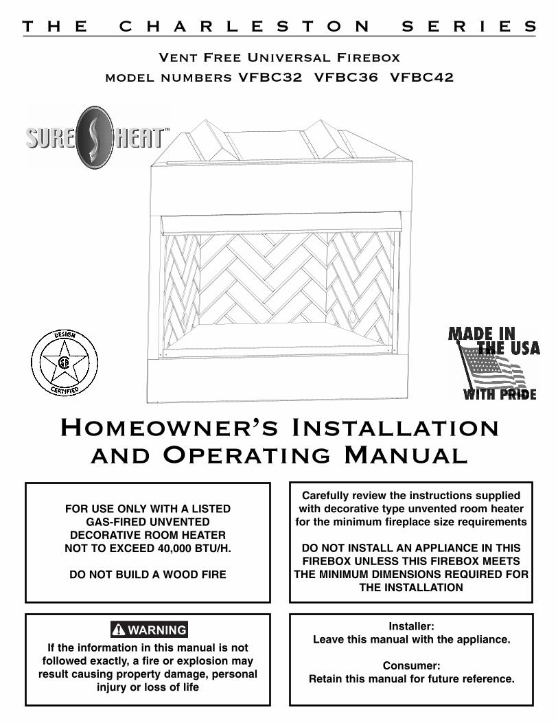
FOR USE ONLY WITH A LISTED GAS-FIRED UNVENTED
DECORATIVE ROOM HEATERNOT TO EXCEED 40,000 BTU/H.
DO NOT BUILD A WOOD FIRE
Carefully review the instructions suppliedwith decorative type unvented room heater
for the minimum fireplace size requirements
DO NOT INSTALL AN APPLIANCE IN THISFIREBOX UNLESS THIS FIREBOX MEETS
THE MINIMUM DIMENSIONS REQUIRED FORTHE INSTALLATION
Homeowner’s Installation and Operating Manual
Vent Free Universal Fireboxmodel numbers VFBC32 VFBC36 VFBC42
Installer: Leave this manual with the appliance.
Consumer: Retain this manual for future reference.
T H E C H A R L E S T O N S E R I E S
If the information in this manual is not followed exactly, a fire or explosion may
result causing property damage, personalinjury or loss of life
Congratulations!
2
INSTALLER/CONSUMERSAFETY INFORMATION
Read and save these instructions.
This book contains your installation instructions and should be kept in a safe place. For you to realizeall the advantages and use of the reliable service that has been engineered into your Sure HeatManufacturing fireplace, you must carefully follow all of the instructions contained in this book regardinginstallation and operation of the fireplace.
These instructions should be read carefully in their entirety before beginning installation of the fireplace.
It is suggested that you wear work gloves and safety glasses to protect your hands and eyes wheninstalling your fireplace. NOTE: Authorities having jurisdiction (i.e. building inspectors, fire marshals, etc.)should be consulted before installation to determine the need to obtain a permit.
These fireboxes are approved as universal fireboxes and can be paired with any ANSI Z21.11.2approved vent free gas log set. The vent free log manufacturer’s instructions, including theirrequired dimensional clearances for firebox size, must be followed.
Refer to the manual that is packed with the log set for operating instructions.
Table of Contents
Safety Information . . . . . . . . . . . . . . . . . . . . . . . . . . . . . . . . . . . . . . . . . . . . . . . .3Product Features . . . . . . . . . . . . . . . . . . . . . . . . . . . . . . . . . . . . . . . . . . . . . . . . .4Hearth Dimensions . . . . . . . . . . . . . . . . . . . . . . . . . . . . . . . . . . . . . . . . . . . . . . .5Fireplace Framing Dimensions . . . . . . . . . . . . . . . . . . . . . . . . . . . . . . . . . . . . . .6Installation Instructions . . . . . . . . . . . . . . . . . . . . . . . . . . . . . . . . . . . . . . . . . . . .7-14Locating the Fireplace . . . . . . . . . . . . . . . . . . . . . . . . . . . . . . . . . . . . . . . . . . . . .7Gas Line . . . . . . . . . . . . . . . . . . . . . . . . . . . . . . . . . . . . . . . . . . . . . . . . . . . . . . .7Drafts . . . . . . . . . . . . . . . . . . . . . . . . . . . . . . . . . . . . . . . . . . . . . . . . . . . . . . . . . .8Clearances . . . . . . . . . . . . . . . . . . . . . . . . . . . . . . . . . . . . . . . . . . . . . . . . . . . . . .8Installing the Firebox . . . . . . . . . . . . . . . . . . . . . . . . . . . . . . . . . . . . . . . . . . . . . .9Finishing the Fireplace . . . . . . . . . . . . . . . . . . . . . . . . . . . . . . . . . . . . . . . . . . . .11Hearth Extension . . . . . . . . . . . . . . . . . . . . . . . . . . . . . . . . . . . . . . . . . . . . . . . . .11Install Optional Outside Air Kit . . . . . . . . . . . . . . . . . . . . . . . . . . . . . . . . . . . . . . .11Blower Installation . . . . . . . . . . . . . . . . . . . . . . . . . . . . . . . . . . . . . . . . . . . . . . . .13Replacement Parts . . . . . . . . . . . . . . . . . . . . . . . . . . . . . . . . . . . . . . . . . . . . . . .15Servicing . . . . . . . . . . . . . . . . . . . . . . . . . . . . . . . . . . . . . . . . . . . . . . . . . . . . . . .15Warranty . . . . . . . . . . . . . . . . . . . . . . . . . . . . . . . . . . . . . . . . . . . . . . . . . . . . . . .16
General Installation Information
In planning the installation for the appliance it is necessary to determine where the unit is to be installedand whether optional accessories are desired. Gas supply piping should also be planned. The followingsteps represent the normal sequence of installation. Each installation is unique, however, and mightrequire a different sequence.
1. Position firebox prior to framing or into prepared framing.
2. Plumb gas line. (Gas connections should only be performed by an experienced, licensed/certified tradesman).
3. Install vent-free gas log heater per the instructions provided with the vent-free gas log heater.
4. Complete finish wall material, surround and optional hearth extension to your individual taste.
Safety Information
3
IMPORTANT
Read these instructions carefully before installing or trying tooperate a vent-free gas heater in this firebox.
1. Due to high temperatures, the appliance should be located out oftraffic and away from furniture and draperies.
2. Children and adults should be alerted to the hazard of high surface temperature and should stay away to avoid burns orclothing ignition.
3. Young children should be carefully supervised when they are inthe same room with the appliance.
4. Do not place clothing or other flammable material on or near the appliance.
5. Any safety screen or guard removed for servicing an appliancemust be replaced prior to operating the heater.
6. Installation and repair should be done by a qualified service person.
7. To prevent malfunction and/or sooting, an unvented gas heatershould be cleaned before use at least annually by a professional service person. More frequent cleaning may berequired due to excessive lint from carpeting, bedding material,etc. It is imperative that control compartments, burners and circulating air passages be kept clean.
8. CARBON MONOXIDE POISONING: Early signs of carbonmonoxide poisoning are similar to the flu with headaches, dizziness and/or nausea. If you have these signs, obtain freshair immediately. Have the heater serviced as it may not beoperating properly.
9. The installation must conform with local codes or, in the absenceof local codes, with the National Fuel Gas Code, ANSIZ223.1/NFPA54.
10. This unit complies with ANSI Z21.91.2001 ventless firebox enclosures for gas-fired unvented decorative room heaters.
11. Do not install heater in a bathroom or bedroom.
12. Correct installation of the logs, proper location of the heater, andannual cleaning are necessary to avoid potential problems withsooting. Sooting, resulting from improper installation or operation, can settle on surfaces outside the fireplace. See logplacement instructions for proper installation.
13. Avoid any drafts that alter burner flame patterns. Do not allowfans to blow directly into fireplace. Do not place a blower insideburn area of firebox. Ceiling fans may create drafts that alterburner flame patterns. Sooting and improper burning will occur.
14. Candles, incense oil lamps, etc. produce combustion byproducts including soot. Vent-free appliances willnot filter or clean soot produced these types of products. Inaddition, the smoke and/or aromatics (scents) may be reburntin the vent-free appliance which can produce odors. It is recommended to minimize the use of candles, incense, etc.while the vent-free appliance is in operation.
15. An unvented gas-fired heater uses air (oxygen) from the room inwhich it is installed. Provisions for adequate combustion andventilation air must be provided. See installation guidelines.
16. Keep room area clear and free from combustible materials,gasoline and other flammable vapors and liquids.
17. Unvented gas heaters are a supplemental zone heater. They arenot intended to be a primary heating appliance.
18. Unvented gas heaters emit moisture into the living area. In mosthomes of average construction, this does not pose a problem.In houses of extremely tight construction, additional mechanicalventilation is recommended.
19. During manufacturing, fabricating and shipping, various components of this appliance are treated with certain oils, filmsor bonding agents. These chemicals are not harmful but mayproduce annoying smoke and smells as they are burned offduring the initial operation of the appliance, possibly causingheadaches, or eye or lung irritation. This is a normal and temporary occurrence.
The initial break-in operation should last two to three hours withthe burner at the highest setting. Provide maximum ventilationby opening windows or doors to allow odors to dissipate. Anyodors remaining after this initial break-in period will be slightand will disappear with continual use.
20. Input ratings are shown in BTU per hour and are for elevationsup to 2,000 feet. For elevations above 2,000 feet, input ratingsshould be reduced 4% for each 1,000 feet above sea level.Refer to the National Fuel Gas Code.
21. The appliance and its appliance main gas valve must be disconnected from the gas supply piping systems during anypressure testing of that system at test pressures in excess of1/2 psig (3.5kPa).
22. The appliance must be isolated from the gas supply piping system by closing its equipment shutoff valve during any pressure testing of the gas supply piping system at test pressures equal to or less than 1/2 psig (3.5 kPa).
23. Do not use this room heater if any part has been under water.Immediately call a qualified service technician to inspect theroom heater and to replace any part of the control system andany gas control which has been under water.
24. Never burn solid fuels in a fireplace where an unvented roomheater is installed.
25. Always have a fireplace screen in place when the appliance is inoperation, and unless other provisions for combustion air areprovided, the screen shall have an opening(s) for induction ofcombustion air.
26. Do not fill spaces around the firebox with insulation or othermaterials. These spaces must be maintained to prevent the firebox from coming in contact with combustible materials.
• Any change to this heater or its controls can be dangerous.
• Improper installation or use of the heater cancause serious injury or death from fire, burns,explosion or carbon monoxide poisoning.
• Do NOT allow fans to blow directly into the fireplace. Avoid any drafts that alter burnerflame patterns.
Product Features
4
Do not attempt to burn solid wood fuels, vented gas log sets, or any other combustible in thisunvented firebox. Also, do not install a vent-free gas log set in this firebox if the minimum clearance and height requirements of the log set are too large for the firebox.
You have purchased a vent-free firebox. This installation manual will enable you to obtain a safe, efficientand dependable installation of your vent-free firebox system.
Do not alter or modify the firebox or its components under any circumstances. Any modifications or alterationof the firebox system, including but not limited to the firebox and accessories, may void the warranty, listings andapprovals of this system, and could result in an unsafe and potentially dangerous installation.
Before You Start
Carefully inspect the contents for shipping damage. If any parts are missing or damaged, immediately informthe dealer from whom you purchased the appliance. Do not attempt to install any art of the appliance unless youhave all the parts in good condition.
Make Sure That You Have Received All Parts
Check your packing list to verify that all listed parts have been received. You should have the following:
1. Vent-Free Gas Firebox 3. Installation and Operating Manual
2. Canopy 4. Five (5) sheet metal screws for canopy.
What You Will Need For Installation
Tools
• Phillips screwdriver • Square
• Hammer • Saw and/or sabersaw
• Tee Joint • Electric drill and bits
• Level • Pipe wrench
• Measuring Tape • Piping complying with local codes
• Pliers • Pipe sealant approved for use with propane/L.P.G. (resistant to sulfer compounds)
Building Supplies
• Framing materials
• Wall finishing materials
• Caulking material (non-combustible)
• Fireplace surround materials(non-combustible)
Notice:
Illustrations shown in this manual reflect "typical" installations with nominal dimensions and are for designand framing reference only. Actual installations may vary due to individual design preferences. However,always maintain minimum clearances to combustible materials and do not violate any specific installationrequirements.
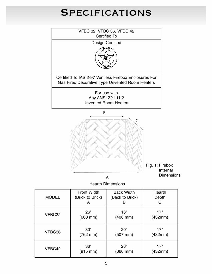
Specifications
5
VFBC 32, VFBC 36, VFBC 42Certified To
Design Certified
Certified To IAS 2-97 Ventless Firebox Enclosures ForGas Fired Decorative Type Unvented Room Heaters
For use with Any ANSI Z21.11.2
Unvented Room Heaters
MODELFront Width
(Brick to Brick)A
Back Width(Back to Brick)
B
HearthDepth
C
VFBC3226"
(660 mm)16"
(406 mm)17"
(432mm)
VFBC3630"
(762 mm)20"
(507 mm)17"
(432mm)
VFBC42 36"
(915 mm)26"
(660 mm)17"
(432mm)
A
B
C
Hearth Dimensions
Fig. 1: FireboxInternal Dimensions
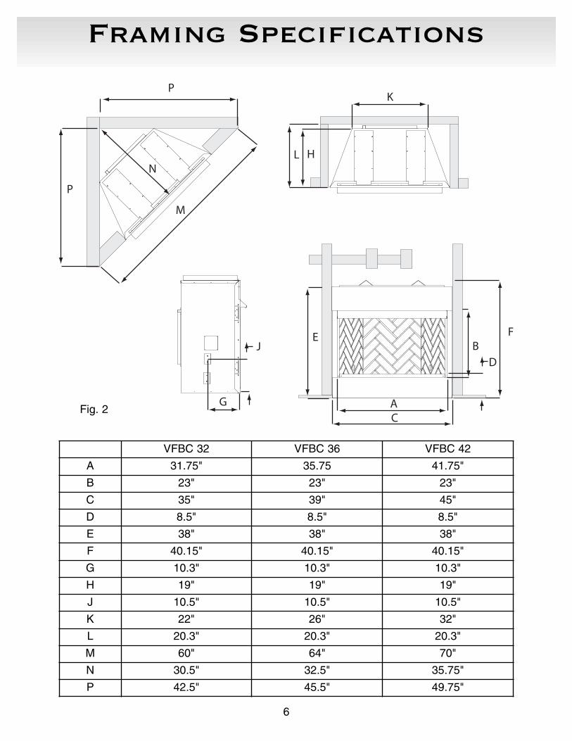
Framing Specifications
6
VFBC 32 VFBC 36 VFBC 42
A 31.75" 35.75 41.75"
B 23" 23" 23"
C 35" 39" 45"
D 8.5" 8.5" 8.5"
E 38" 38" 38"
F 40.15" 40.15" 40.15"
G 10.3" 10.3" 10.3"
H 19" 19" 19"
J 10.5" 10.5" 10.5"
K 22" 26" 32"
L 20.3" 20.3" 20.3"
M 60" 64" 70"
N 30.5" 32.5" 35.75"
P 42.5" 45.5" 49.75"
AC
B
D
FE
K
L H
J
G
P
M
N
P
Fig. 2
Installation and Instructions
7
Locating the Fireplace
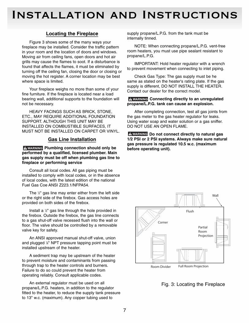
Figure 3 shows some of the many ways your fireplace may be installed. Consider the traffic patternin your room and the location of doors and windows.Moving air from ceiling fans, open doors and hot airgrills may cause the flames to soot. If a disturbance isfound that affects the flames, it must be eliminated byturning off the ceiling fan, closing the door or closing ormoving the hot register. A corner location may be bestwhere space is limited.
Your fireplace weighs no more than some of yourfine furniture. If the fireplace is located near a loadbearing wall, additional supports to the foundation willnot be necessary.
HEAVY FACINGS SUCH AS BRICK, STONE,ETC., MAY REQUIRE ADDITIONAL FOUNDATIONSUPPORT. ALTHOUGH THIS UNIT MAY BEINSTALLED ON COMBUSTIBLE SURFACES, ITMUST NOT BE INSTALLED ON CARPET OR VINYL.
Gas Line Installation
Plumbing connection should only beperformed by a qualified, licensed plumber. Maingas supply must be off when plumbing gas line tofireplace or performing service
Consult all local codes. All gas piping must beinstalled to comply with local codes, or in the absenceof local codes, with the latest edition of the nationalFuel Gas Coe ANSI Z223.1/NFPA54.
The 1⁄2" gas line may enter either from the left sideor the right side of the firebox. Gas access holes areprovided on both sides of the firebox.
Install a 1⁄2" gas line through the hole provided inthe firebox. Outside the firebox, the gas line connectsto a gas shut-off valve recessed flush into the wall orfloor. The valve should be controlled by a removablevalve key for safety.
An ANSI approved manual shut-off valve, unionand plugged 1⁄8" NPT pressure tapping point must beinstalled upstream of the heater.
A sediment trap may be upstream of the heater to prevent moisture and contaminants from passingthrough trap to the heater controls and burners. Failure to do so could prevent the heater from operating reliably. Consult applicable codes.
An external regulator must be used on allpropane/L.P.G. heaters, in addition to the regulator fitted to the heater, to reduce the supply tank pressureto 13" w.c. (maximum). Any copper tubing used to
supply propane/L.P.G. from the tank must be internally tinned.
NOTE: When connecting propane/L.P.G. vent-freeroom heaters, you must use pipe sealant resistant topropane/L.P.G.
IMPORTANT: Hold heater regulator with a wrenchto prevent movement when connecting to inlet piping.
Check Gas Type: The gas supply must be hesame as stated on the heater's rating plate. If the gassupply is different, DO NOT INSTALL THE HEATER.Contact our dealer for the correct model.
Connecting directly to an unregulatedpropane/L.P.G. tank can cause an explosion.
After completing connection, test all gas joints fromthe gas meter to the gas heater regulator for leaks.Using water soap and water solution or a gas sniffer.DO NOT USE AN OPEN FLAME.
Do not connect directly to natural gas1/2 PSI or 2 PSI systems. Always make sure naturalgas pressure is regulated 10.5 w.c. (maximumbefore operating unit).
Wall
Full Room Projection
Flush
PartialRoomProjection
Corner
Room Divider
Fig. 3: Locating the Fireplace
Installation and Instructions
8
Drafts
Do not locate the fireplace in high traffic areas orareas exposed to high drafts and winds. Locate thefireplace away from furniture and draperies.
Fireplace Clearances
The fireplace may be placed directly on a combustible floor, against a combustible wall atmarked clearances or on a raised wooden platform.
If the fireplace is to be installed on a raised wooden platform, the platform must be a continuouslevel surface. The fireplace must be secured in placeso it cannot shift positions. The nailing flanges on thesides of the firebox make securing it to the framingeasy. They were designed to allow the installation of wallboard or plywood flush with the face of the fire-place.
Only the header (Fig. 2, page 6) may rest on thestandoffs on top of the firebox.
When the fireplace is installed over carpeting,vinyl, tile or any combustible material other than woodflooring, it must be installed on a metal or wood panelextending its full width and depth. Alternatively, the carpeting, vinyl, tile, etc., may be removed frombeneath the fireplace before installing.
COMBUSTIBLE MATERIALS MUST NOT BEINSTALLED OVER OR TOUCH ANY BLACK PAINTEDSURFACE.
Clearances
To ensure a safe installation the following instructions must be carefully observed.
1. Sidewall Clearances: Clearances from the side ofthe fireplace opening to any combustible wallshould not be less that 9".
2. Ceiling Clearances: The ceiling height should not be less than 42" from the top of the fireplace opening.
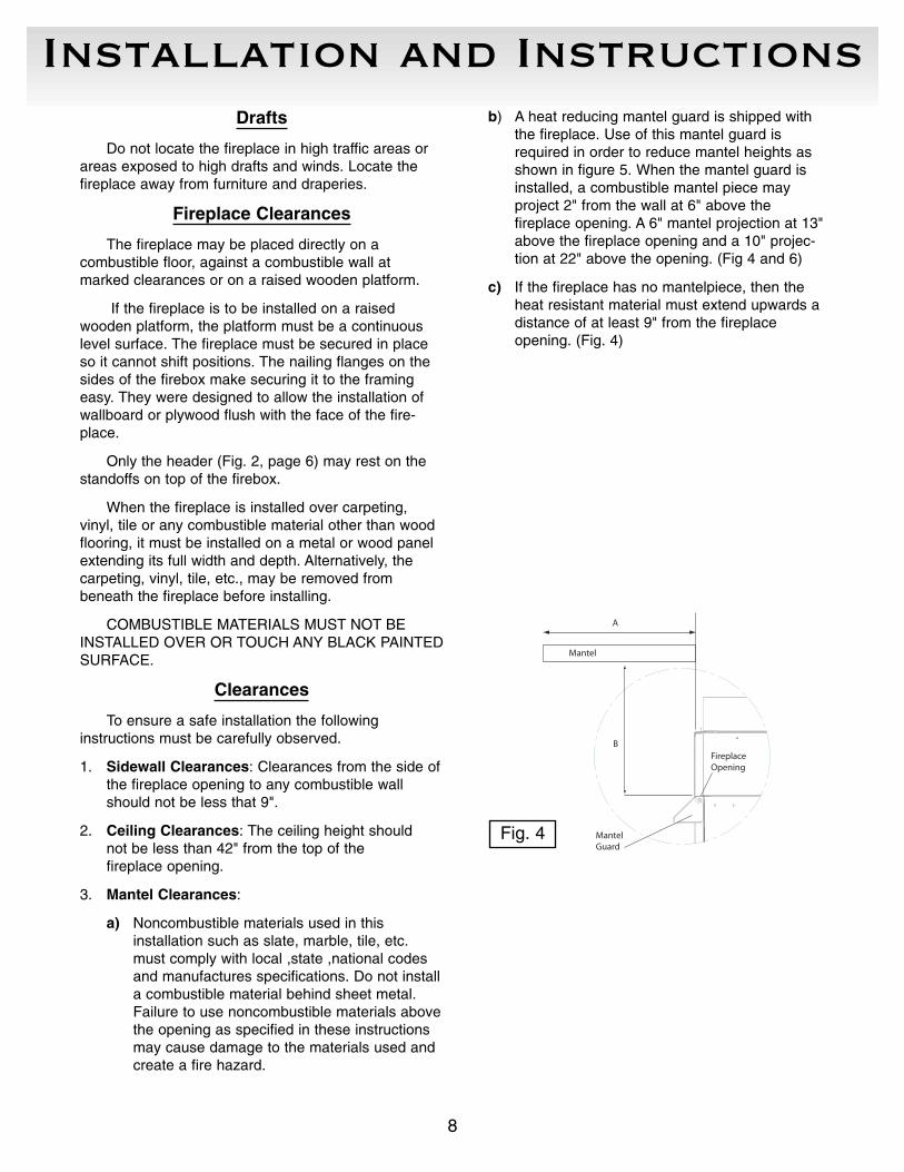
3. Mantel Clearances:
a) Noncombustible materials used in this installation such as slate, marble, tile, etc.must comply with local ,state ,national codesand manufactures specifications. Do not installa combustible material behind sheet metal.Failure to use noncombustible materials abovethe opening as specified in these instructionsmay cause damage to the materials used andcreate a fire hazard.
b) A heat reducing mantel guard is shipped withthe fireplace. Use of this mantel guard isrequired in order to reduce mantel heights asshown in figure 5. When the mantel guard isinstalled, a combustible mantel piece may project 2" from the wall at 6" above the fireplace opening. A 6" mantel projection at 13"above the fireplace opening and a 10" projec-tion at 22" above the opening. (Fig 4 and 6)
c) If the fireplace has no mantelpiece, then theheat resistant material must extend upwards adistance of at least 9" from the fireplace opening. (Fig. 4)
A
B
MantelGuard
Mantel
FireplaceOpening
Fig. 4
Installation and Instructions
9
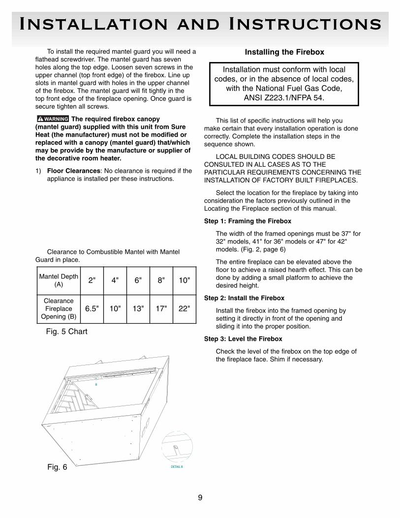
To install the required mantel guard you will need aflathead screwdriver. The mantel guard has sevenholes along the top edge. Loosen seven screws in theupper channel (top front edge) of the firebox. Line upslots in mantel guard with holes in the upper channelof the firebox. The mantel guard will fit tightly in thetop front edge of the fireplace opening. Once guard issecure tighten all screws.
The required firebox canopy (mantel guard) supplied with this unit from SureHeat (the manufacturer) must not be modified orreplaced with a canopy (mantel guard) that/whichmay be provide by the manufacture or supplier ofthe decorative room heater.
1) Floor Clearances: No clearance is required if theappliance is installed per these instructions.
Installing the Firebox
This list of specific instructions will help you make certain that every installation operation is donecorrectly. Complete the installation steps in thesequence shown.
LOCAL BUILDING CODES SHOULD BE CONSULTED IN ALL CASES AS TO THE PARTICULAR REQUIREMENTS CONCERNING THE INSTALLATION OF FACTORY BUILT FIREPLACES.
Select the location for the fireplace by taking intoconsideration the factors previously outlined in theLocating the Fireplace section of this manual.
Step 1: Framing the Firebox
The width of the framed openings must be 37" for32" models, 41" for 36" models or 47" for 42" models. (Fig. 2, page 6)
The entire fireplace can be elevated above thefloor to achieve a raised hearth effect. This can bedone by adding a small platform to achieve thedesired height.
Step 2: Install the Firebox
Install the firebox into the framed opening by setting it directly in front of the opening and sliding it into the proper position.
Step 3: Level the Firebox
Check the level of the firebox on the top edge ofthe fireplace face. Shim if necessary.
Clearance to Combustible Mantel with MantelGuard in place.
Mantel Depth(A) 2" 4" 6" 8" 10"
ClearanceFireplace
Opening (B)6.5" 10" 13" 17" 22"
Fig. 5 Chart
Fig. 6
B
DETAIL B
Installation must conform with localcodes, or in the absence of local codes,
with the National Fuel Gas Code, ANSI Z223.1/NFPA 54.

Installation and Instructions
10
Step 4: Secure the Firebox
Four (4) nailing flanges are supplied with the fireplace to level the box and secure firmly inplace; Bend the nailing flanges from the sides ofthe fireplace as shown in Figure 7.
Note: The nailing flanges have two (2) sets ofholes to allow for adjustment for 1⁄2" or 1" offset ofthe face of the unit. When installing the nailingflanges, choose the set of holes on the nailingflange that fit with your application.
Note: This firebox employs spacers, stand offs andnailing flanges to inhibit contact of parts of the fire-box with combustible construction .
do not alter the spacers or divert from their intended use or notch the framing in any manner.
Step 5: Gas Piping and Connection
The gas piping must be installed in accordancewith local codes or, in the absence of local codes,in accordance with the National Fuel Gas Code,ANSI Z223.1/NFPA 54, latest edition.
Piping should be tested for leaks prior to final wallinstallation. Test for leaks, using a soap and watersolution or any acceptable solution or mechanicalgas leak detector, after completing the connection.DO NOT USE OPEN FLAME.
Step 6: Optional Procedure for Cold Climate Installations
The insulation and sealing of the enclosure aroundthe fireplace is very important in cold climates. Ifthe enclosure is insulated and sealed properly, youcan avoid future cold air problems. The time takento install the firebox correctly is well worthwhile.The following steps are to stop potential cold airproblems. (Do not use Kraft Faced insulation -paper faced)
Insulation of the Fireplace Enclosure
When in a chase or an outside wall, the fireplaceenclosure should be insulated like any other wall ofyour home. Insulation should be installed on the outside wall(s) and the wall about the fireplace. (Do not use Kraft Faced insulation - paper faced.)
Insulate to Seal Under the Fireplace
Insulating under the fireplace is beneficial forinstallations on a concrete slab in cold weather climates. The fireplace should be placed on insulatingboard. It is important that a hard, rigid surface bemaintained, so do not use fiberglass insulation for this purpose.
WHEN INSTALLING A FIREPLACE IN AN INSULATED ENCLOSURE, BE SURE TO MAINTAIN ALL MARKED AIR SPACES. DO NOTUSE KRAFT (PAPER FACED) INSULATION .
Seal Seams
Sealing the seams of the fireplace is beneficial forinstallations in cold weather climates where the outerwall meets the bottom pan and the front face. Also seal between the fireplace and finishing materials. Use high temperature caulk. Refer to Figure 8 fordetails of sealing spaces between the fireplace and finishing materials.
DETAIL C
C
Fig. 7StandOff
Caulking or Sealant
NoncombustibleInsulation
Finishing Material
Top View
Side View
Caulking or Sealant
Noncombustible Material
Finishing Material
Insulation
Stud
Fig. 8
Installation and Instructions
11
Finishing the Fireplace
There are a wide variety of finishing materialsavailable for your fireplace from formal wall treatmentswith marble and mantles to rustic wood paneling, stoneor brick.
IT IS IMPORTANT THAT THE BLACK FACE OFTHE FIREPLACE NOT BE COVERED WITH ANYTYPE OF COMBUSTIBLE MATERIAL.
Noncombustible facing materials such as marble,brick or ceramic tile may overlap the black face of thefireplace up to the opening on either side of the fireplace. Seal all joints between the black fireplaceface and the wall covering with a heat-resistant material such as rock wool insulation or mortar. Besure to use high temperature adhesive or mortar whenanchoring brick, stone or tile to the face of the fireplace. Check to see whether man-made brick andstone are made of noncombustible materials beforeusing them on the face of the fireplace. Some of theseproducts contain combustible materials. Combustiblewall coverings such as paneling or wallboard may not overlap the black face of the fireplace. The spacebetween the wall covering and the fireplace should besealed with a heat-resistant material such as rock wool insulation or mortar.
NOTE: An “L” shaped steel lintel must be installedacross the top of the firebox opening where facingmaterials such as brick or stone are used on the faceof the firebox. It acts as a support/firestop. It should beattached to the face of the fireplace with screws andsealed to the fireplace with a heat-resistant sealer.
These vent free fireplaces are not to beused with any TYPE or MODEL of glass doors.
Fireplace screens must be in the closed position across the entire hearth opening prior to the operation of the decorativeroom heater.
NOTE: Information on provisions for adequatecombustion and ventilation air are located in theunvented room heaters installation instructions.
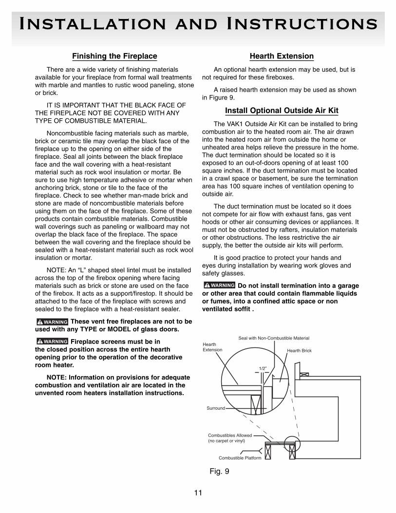
Hearth Extension
An optional hearth extension may be used, but isnot required for these fireboxes.
A raised hearth extension may be used as shownin Figure 9.
Install Optional Outside Air Kit
The VAK1 Outside Air Kit can be installed to bringcombustion air to the heated room air. The air drawninto the heated room air from outside the home orunheated area helps relieve the pressure in the home.The duct termination should be located so it isexposed to an out-of-doors opening of at least 100square inches. If the duct termination must be locatedin a crawl space or basement, be sure the terminationarea has 100 square inches of ventilation opening tooutside air.
The duct termination must be located so it doesnot compete for air flow with exhaust fans, gas venthoods or other air consuming devices or appliances. Itmust not be obstructed by rafters, insulation materialsor other obstructions. The less restrictive the air supply, the better the outside air kits will perform.
It is good practice to protect your hands and eyes during installation by wearing work gloves andsafety glasses.
Do not install termination into a garageor other area that could contain flammable liquidsor fumes, into a confined attic space or non ventilated soffit .
Combustible Platform
Combustibles Allowed(no carpet or vinyl)
Surround
1/2”
Seal with Non-Combustible Material
Hearth BrickHearthExtension
Fig. 9
Installation and Instructions
12
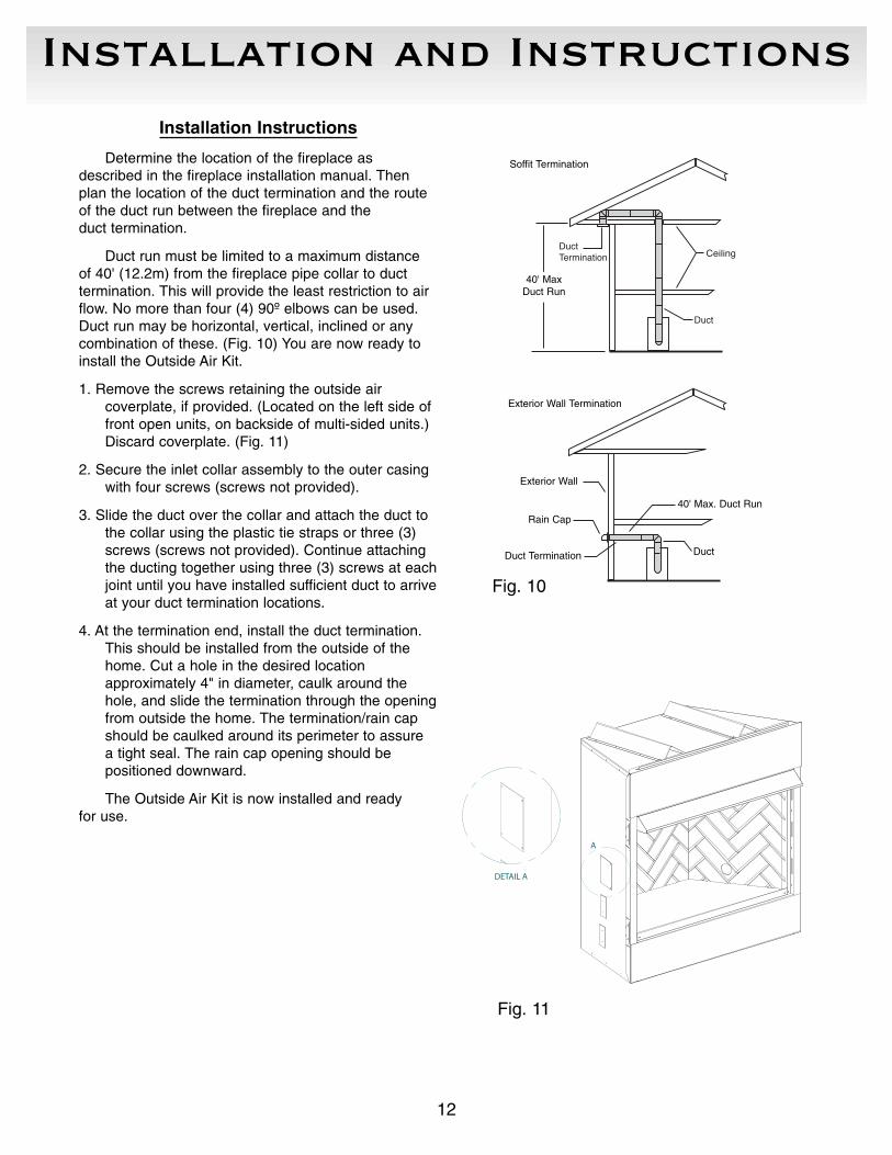
Installation Instructions
Determine the location of the fireplace asdescribed in the fireplace installation manual. Thenplan the location of the duct termination and the routeof the duct run between the fireplace and the duct termination.
Duct run must be limited to a maximum distance of 40' (12.2m) from the fireplace pipe collar to duct termination. This will provide the least restriction to airflow. No more than four (4) 90º elbows can be used.Duct run may be horizontal, vertical, inclined or anycombination of these. (Fig. 10) You are now ready toinstall the Outside Air Kit.
1. Remove the screws retaining the outside air coverplate, if provided. (Located on the left side offront open units, on backside of multi-sided units.)Discard coverplate. (Fig. 11)
2. Secure the inlet collar assembly to the outer casingwith four screws (screws not provided).
3. Slide the duct over the collar and attach the duct tothe collar using the plastic tie straps or three (3)screws (screws not provided). Continue attachingthe ducting together using three (3) screws at eachjoint until you have installed sufficient duct to arriveat your duct termination locations.
4. At the termination end, install the duct termination.This should be installed from the outside of thehome. Cut a hole in the desired location approximately 4" in diameter, caulk around thehole, and slide the termination through the openingfrom outside the home. The termination/rain cap should be caulked around its perimeter to assure a tight seal. The rain cap opening should be positioned downward.
The Outside Air Kit is now installed and ready for use.
A
DETAIL A
Fig. 11
Ceiling
Duct
DuctTermination
40ʼ MaxDuct Run
Soff it Termination
Exterior Wall T ermination
Exterior Wall
40ʼ Max. Duct Run
DuctDuct Termination
Rain Cap
Fig. 10
Soffit Termination
40' MaxDuct Run
Exterior Wall Termination
Exterior Wall
Rain Cap
40' Max. Duct Run
DuctDuct Termination
Installation and Instructions
13
Electrical Junction Box
Wiring should be connected at a customer provided junction box, outside the firebox, prior to theinstallation of the blower kit.
Electrical Services
If an electrical supply of 120V is being roughed into the fireplace junction box to provide for future installation of the optional blower kit, the wiring shouldbe connected to the junction box.
NOTE: All electrical connections (Fig. 12) are tobe made in accordance with CSA Standard C22.1Canadian Electrical Code part 1 or with the NationalElectrical Code, ANSI/NFPA 70 (latest edition) and/orin accordance with local codes.
Install Optional Blower/Fan Kit – BL102
NOTE: A FEW BASIC SAFETY RULES BEFOREYOU START:
1. Make sure you have and are using/wearing properpersonal safety devices such as but not limited togloves, safety eye glasses/eye protection .
2. Check to ensure that electrical service has beenprovided to the junction box located in the bottomchamber of the firebox.
3. Check local building codes before installation of thefirebox and blower kit.
4. All wiring must be installed and/or inspected as necessary to comply with the local authority having jurisdiction.
5. The circuit breaker controlling the power supply tothe pre-wired junction box in the appliance must bein the off position before beginning installation ofthe blower .
6. The appliance, when installed, must be electricallygrounded in accordance with local codes or – inthe absence of local codes – with the NationalElectrical Code, ANSI/NFPA 70 or the CanadianElectrical Code, CSA C22.1
M
FIREBOX ENCLOSUREINSTALLER CONNECT TO
110VAC HOUSE WIRINGPER APPLICABLE
LOCAL CODES BLOWER MOTOR ACCESSORY
SPST BLOWER SWITCH
STEEL HANDI-BOX W/SINGLE GANG
RECEPTACLE
VFBC WIRING DIAGRAM - ALL SIZESFig. 12
Installation and Instructions
14
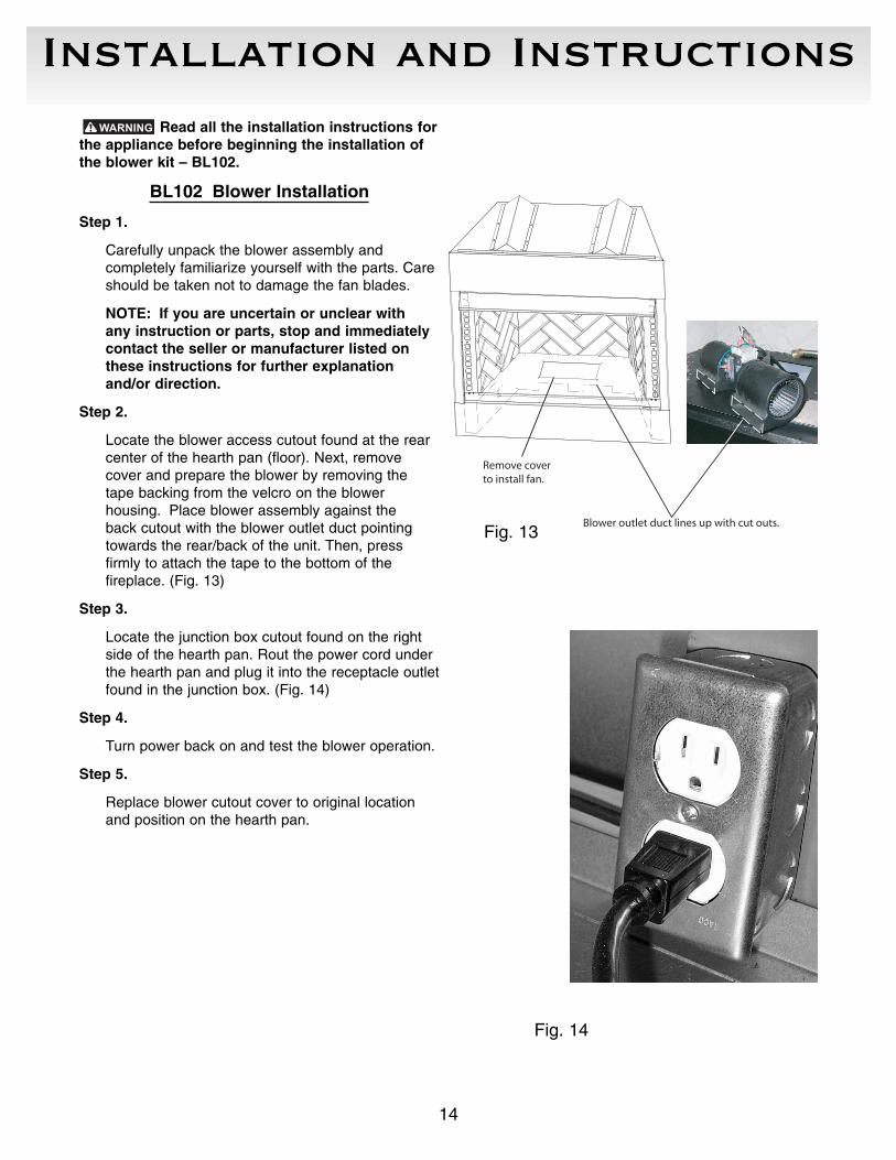
Read all the installation instructions forthe appliance before beginning the installation ofthe blower kit – BL102.
BL102 Blower Installation
Step 1.
Carefully unpack the blower assembly and completely familiarize yourself with the parts. Careshould be taken not to damage the fan blades.
NOTE: If you are uncertain or unclear with any instruction or parts, stop and immediatelycontact the seller or manufacturer listed onthese instructions for further explanationand/or direction.
Step 2.
Locate the blower access cutout found at the rearcenter of the hearth pan (floor). Next, removecover and prepare the blower by removing thetape backing from the velcro on the blower housing. Place blower assembly against the back cutout with the blower outlet duct pointingtowards the rear/back of the unit. Then, press firmly to attach the tape to the bottom of the fireplace. (Fig. 13)
Step 3.
Locate the junction box cutout found on the rightside of the hearth pan. Rout the power cord underthe hearth pan and plug it into the receptacle outletfound in the junction box. (Fig. 14)
Step 4.
Turn power back on and test the blower operation.
Step 5.
Replace blower cutout cover to original locationand position on the hearth pan.
Fig. 14
Blower outlet duct lines up with cut outs.
Remove coverto install fan.
Fig. 13
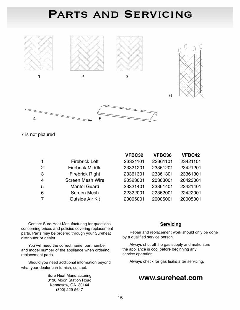
Parts and Servicing
15
1 2 3
4 5
7 is not pictured
VFBC32 VFBC36 VFBC421 Firebrick Left 23321101 23361101 234211012 Firebrick Middle 23321201 23361201 234212013 Firebrick Right 23361301 23361301 233613014 Screen Mesh Wire 20323001 20363001 204230015 Mantel Guard 23321401 23361401 234214016 Screen Mesh 22322001 22362001 224220017 Outside Air Kit 20005001 20005001 20005001
Contact Sure Heat Manufacturing for questions concerning prices and policies covering replacementparts. Parts may be ordered through your Sureheatdistributor or dealer.
You will need the correct name, part number and model number of the appliance when orderingreplacement parts.
Should you need additional information beyondwhat your dealer can furnish, contact:
Sure Heat Manufacturing3130 Moon Station Road
Kennesaw, GA 30144(800) 229-5647
Servicing
Repair and replacement work should only be doneby a qualified service person.
Always shut off the gas supply and make sure the appliance is cool before beginning any service operation.
Always check for gas leaks after servicing.
www.sureheat.com
6
16
RMH-130-0CD1011 11/09/2005
If you have other questions, please contact Customer Service Hotline
(800) 229-5647
LIMITED LIFETIME WARRANTY
Limited Warranty shall apply to the original purchaser at the original installation point only
The following components are warranted for life to the original owner, subject of proof of purchase: Firebox, CombustionChanger, Heat Exchanger.
General Warranty: This Limited Lifetime Warranty will be void if the appliance is not installed by a qualified installer inaccordance with the installation instructions. The Limited Lifetime Warranty will also be void if the appliance is not operated and maintained according to the operating instructions supplied with the appliance, and does not extend to (1)firebox assembly damage by accident, neglect, misuse, abuse, alteration, negligence of others, including the installationthereof by unqualified installers, (2) the costs of removal, reinstallation or transportation of defective parts on the appliance, or (3) incidental or consequential damage. All service work must be performed by an authorized service representative.
This warranty is expressly in lieu of other warranties, express or implied, including the warranty of the merchantability offitness for the purpose and of all other obligations or liabilities. Sure Heat Mfg. Co. does not assume for it any otter obligations or liabilities in connection with the sale or use of the appliance. In states that do not allow limitation on howlong an implied warranty lasts, or do not allow exclusion of indirect damage, those limitations of exclusions may not applyto you. You may also have the additional rights not covered in this Limited Lifetime Warranty.
Sure Heat Mfg. Co. reserves the right to investigate any and all claims against the Limited Lifetime Warranty and decideupon method of settlement.
All costs for removal and reinstallation are the expressed responsibility of the purchaser.
For repair or replacement of a defective part or parts, contact our customer service department at 1-800-229-5647. Youwill be asked to provide valid warranty registration, proof of purchase and model number.
Purchased From: ______________________________________________Date: __________________________
Size: o VFBC32 o VFBC36 o VFBC42
Name ______________________________________Date:____________Phone ( ) __________________
Address ____________________________________________________________________________________
City ________________________________________State ____________Zip __________________________
E-mail______________________________________________________________________________________