Embed Size (px)
Citation preview

The Car Jackers
By Jeremy Bonnell Tong Wu
IntroductionRemote controlled car functions: - Heating and Cooling - Start and Stop engine
- Door Lock and Unlock
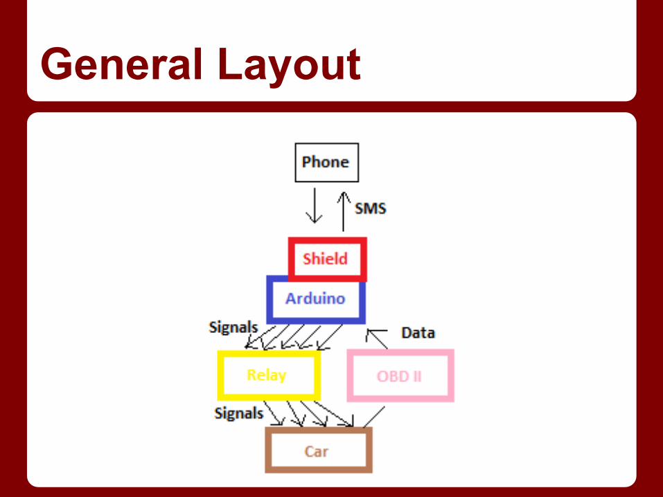
General Layout
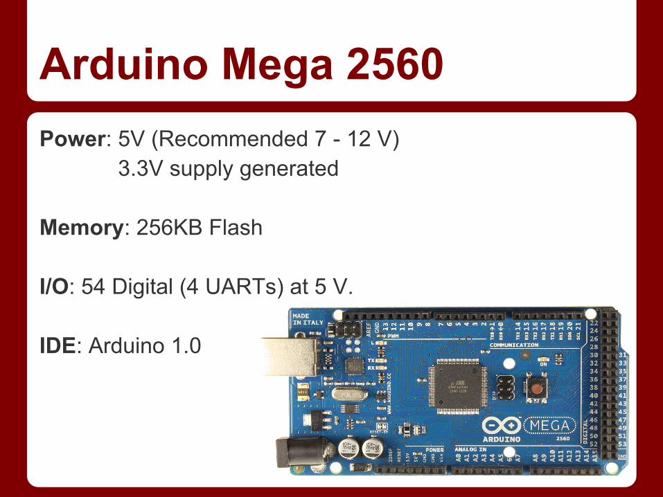
Arduino Mega 2560Power: 5V (Recommended 7 - 12 V)
3.3V supply generated Memory: 256KB Flash I/O: 54 Digital (4 UARTs) at 5 V. IDE: Arduino 1.0
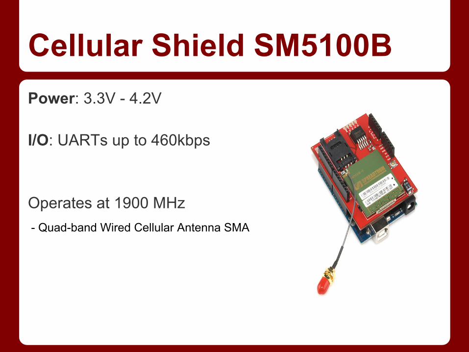
Cellular Shield SM5100BPower: 3.3V - 4.2V I/O: UARTs up to 460kbps Operates at 1900 MHz - Quad-band Wired Cellular Antenna SMA
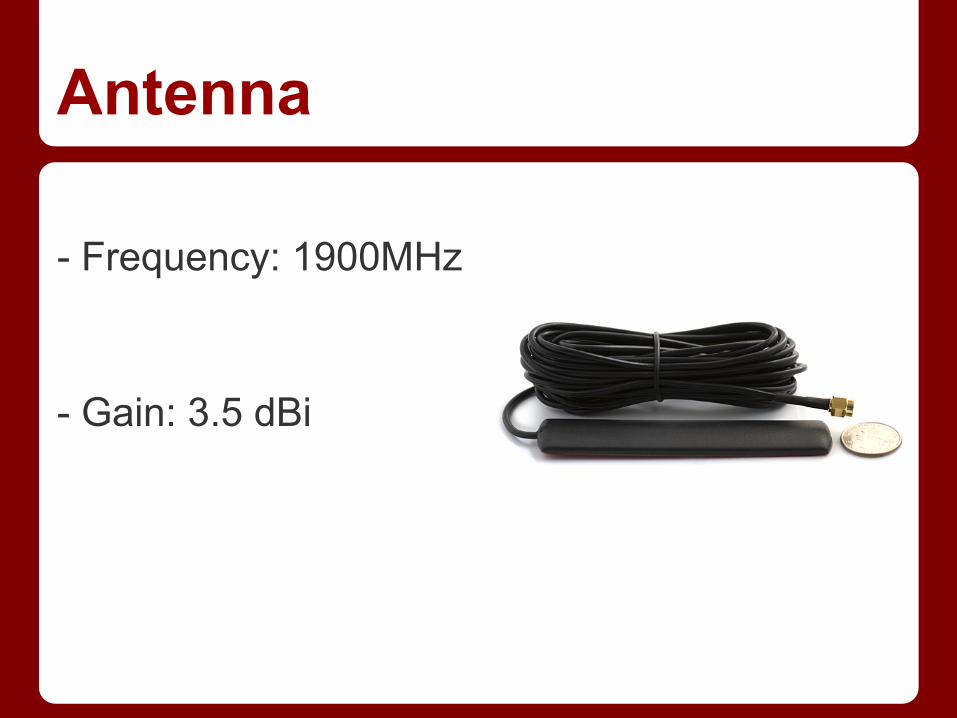
Antenna - Frequency: 1900MHz - Gain: 3.5 dBi

On Board Diagnostic System (OBD-II)
Project Functionality
- To check engine of car Output: Serial port (RS-232)
Connections- Same power, ground, reset, etc. - Use Serial ports - Digital pins on the side (pins 51-53 SPI for digital potentiometer)
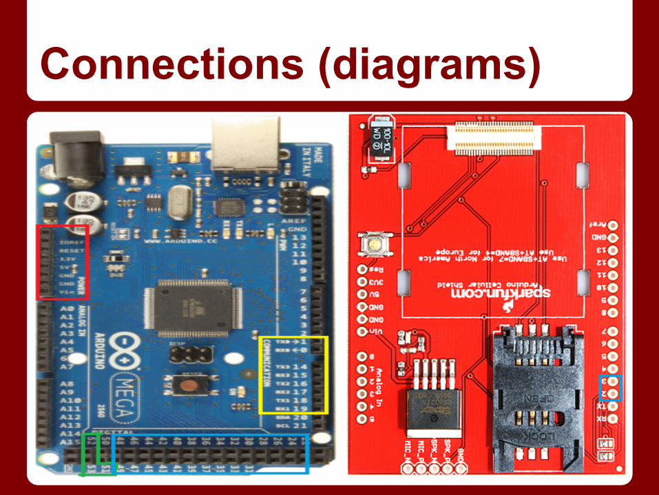
Connections (diagrams)
Software DesignAndroid App. - GUI sends the messages to the cellular shield. Also receives the status Arduino - Parses messages from Android phone then performs tasks.Also sends the status from OBD-II to the phone
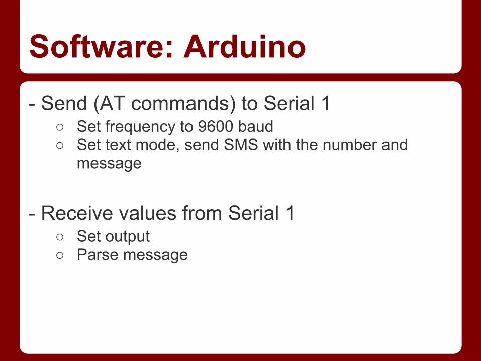
Software: Arduino- Send (AT commands) to Serial 1
○ Set frequency to 9600 baud○ Set text mode, send SMS with the number and
message - Receive values from Serial 1
○ Set output○ Parse message
Android Application- SMS send - SMS receive then parse or display - Onclick handlers for sending SMS with the buttons
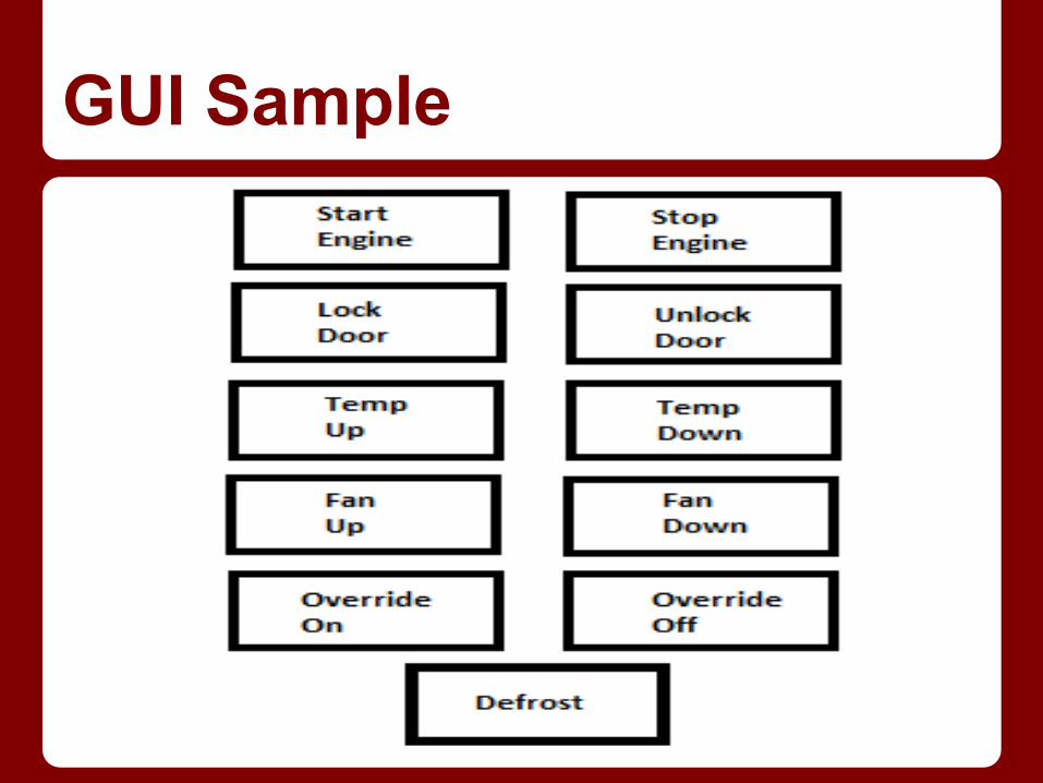
GUI Sample
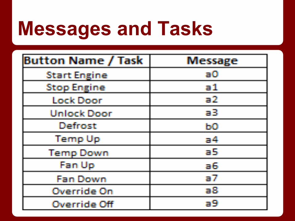
Messages and Tasks
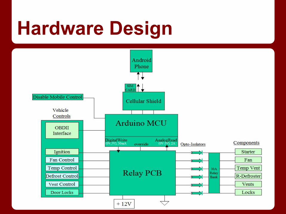
Hardware Design
Relay Driver- PCB design - Amplify Signals from Arduino - Override signal by Arduino used as SELECT line for SPDT Relay Switches - Operates like multiplexer and selects between dashboard controls or Arduino logic

Relay PCB Diagram

Switch Relay
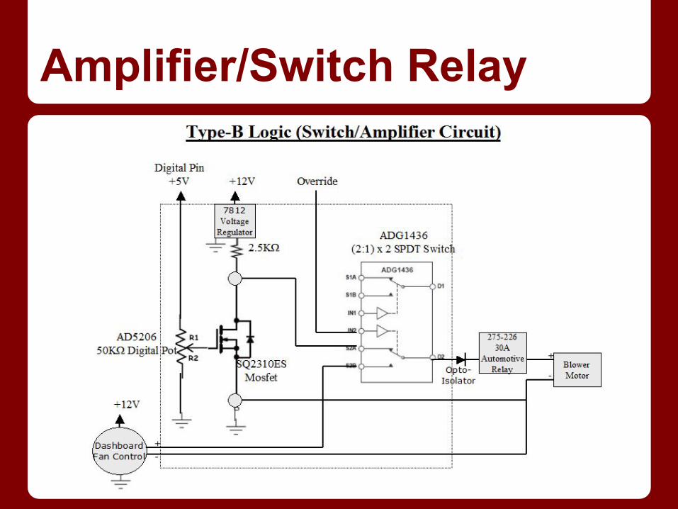
Amplifier/Switch Relay

AD5206 Digital Potentiometer
● 256 positions● Multiple independently programmable channels● 6-channel● Terminal resistance of 10 kΩ, 50 kΩ, or 100 kΩ● 3-wire SPI-compatible serial data input● +2.7 V to +5.5 V single-supply operation

Reverse Engineering- Measure actual voltage and resistor values from each setting of dashboard controls. Typical +12V
● Digital potentiometer values stored in Arduino software for each setting. Used as voltage divider from 5V digital output then amplified by Relay PCB to proper levels
- Translate OBDII codes (Ignition status to Arduino) - Door locks (Monitor) - work in tandem with actual locks. - Locate seat sensor - All Mobile controls disabled after person in driver's seat. 5 second timeout on Ignition Control

2005 Toyota Camry Wiring Diagram-A
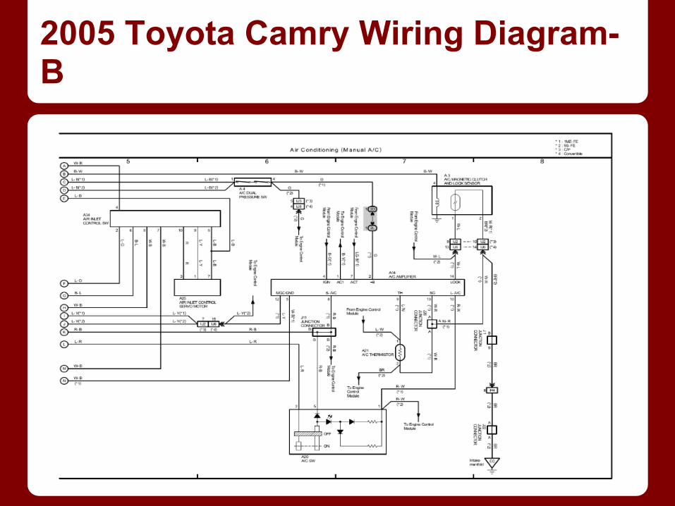
2005 Toyota Camry Wiring Diagram-B
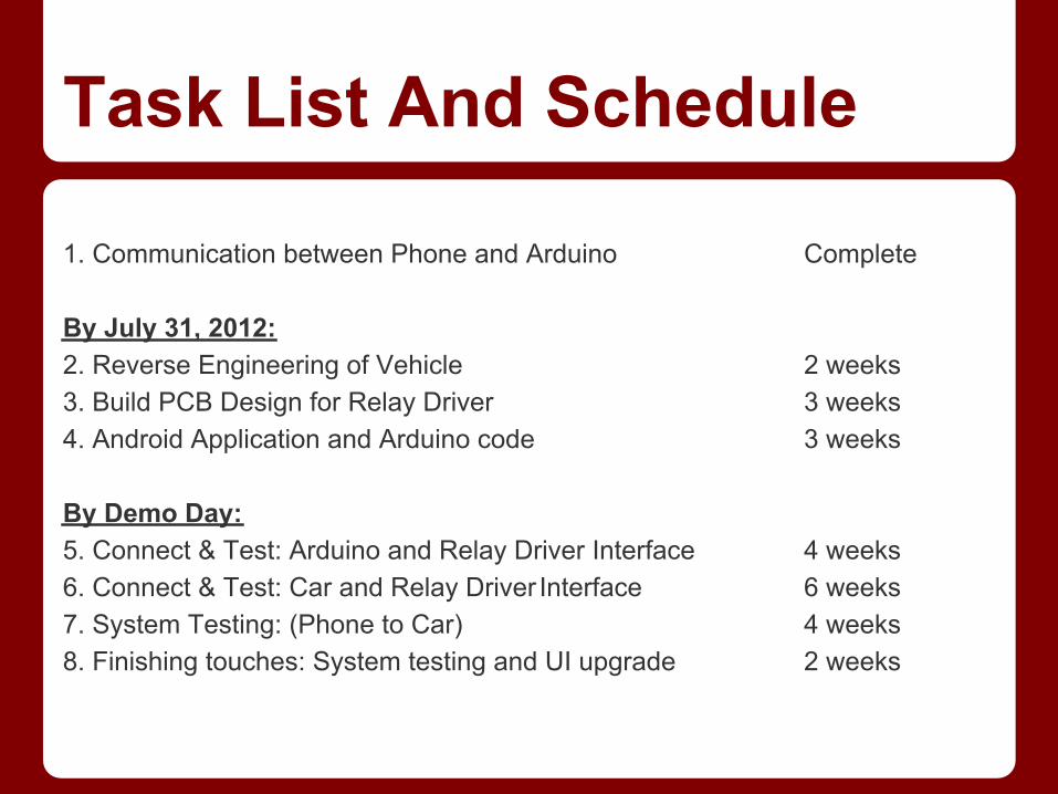
Task List And Schedule 1. Communication between Phone and Arduino Complete By July 31, 2012:2. Reverse Engineering of Vehicle 2 weeks3. Build PCB Design for Relay Driver 3 weeks4. Android Application and Arduino code 3 weeks By Demo Day:5. Connect & Test: Arduino and Relay Driver Interface 4 weeks6. Connect & Test: Car and Relay Driver Interface 6 weeks7. System Testing: (Phone to Car) 4 weeks8. Finishing touches: System testing and UI upgrade 2 weeks Testing/Debugging every step at a time
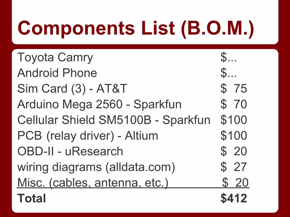
Components List (B.O.M.)Toyota Camry $...Android Phone $...Sim Card (3) - AT&T $ 75Arduino Mega 2560 - Sparkfun $ 70Cellular Shield SM5100B - Sparkfun $100PCB (relay driver) - Altium $100OBD-II - uResearch $ 20wiring diagrams (alldata.com) $ 27Misc. (cables, antenna, etc.) $ 20Total $412
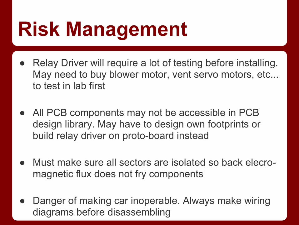
Risk Management● Relay Driver will require a lot of testing before installing.
May need to buy blower motor, vent servo motors, etc... to test in lab first
● All PCB components may not be accessible in PCB
design library. May have to design own footprints or build relay driver on proto-board instead
● Must make sure all sectors are isolated so back elecro-
magnetic flux does not fry components ● Danger of making car inoperable. Always make wiring
diagrams before disassembling
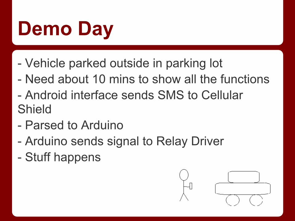
Demo Day- Vehicle parked outside in parking lot- Need about 10 mins to show all the functions- Android interface sends SMS to Cellular Shield- Parsed to Arduino- Arduino sends signal to Relay Driver- Stuff happens

Questions


![Trouble Codes OBDII[1]](https://img.pdfslide.us/doc/110x75/577ce7731a28abf103952cd6/trouble-codes-obdii1.jpg)


