Embed Size (px)
Citation preview
NC STATE UNIVERSITY COLLEGE OF AGRICULTURE & LIFE SCIENCES
PesticideEducationPrograms
The Calibrationof Turfgrass
Boom Sprayersand Spreaders
The Calibrationof Turfgrass
Boom Sprayersand Spreaders
T U R F G R A S S M A N A G E M E N T
& E N V I R O N M E N T A L Q U A L I T Y
ContentsBoom Sprayers ...................................................................................................................................................3
Calibrating Output ............................................................................................................................................3
Measuring Ground Speed .................................................................................................................................3
Pre-calibration Checkup ...................................................................................................................................6
Check Nozzles for Uniform Output ....................................................................................................................6
Selecting the Proper Nozzle Tip ........................................................................................................................7
Measuring Output ............................................................................................................................................8
Making Adjustments .........................................................................................................................................8
Spreaders ...........................................................................................................................................................9
Checking the Distribution Pattern and Swath Width ............................................................................................. 10
Measuring the Application Rate .......................................................................................................................11
Catch-Pan Method .........................................................................................................................................12
Sweep and Weigh Method ..............................................................................................................................12
Weigh Before and After Methods .....................................................................................................................13
Determining How Much to Apply .....................................................................................................................14
Operating the Spreader ..................................................................................................................................14
Measuring the Area to be Treated .....................................................................................................................15
Table of Measurements ..................................................................................................................... Back cover
References .......................................................................................................................................... Back cover
Acknowledgments
Prepared by Wayne G. Buhler, Pesticide Education Specialist, North Carolina Cooperative Extension Service
The author thanks the following for their contributions and assistance:
• Emily Erickson, Crop Science Lecturer
• Matt Martin, Area Specialized Agent, Turfgrass
• Art Bruneau, Extension Turfgrass Specialist
• Gary Roberson, Biological and Agricultural Engineering Specialist
• Joe Neal, Extension Horticulture Specialist, Weed Management
• Fred Yelverton, Extension Crop Science Specialist
This publication was adapted from Water Quality and Sprayer and Spreader Calibration, WQWM-152.
6,000 copies of this public document were printed at a cost of $2,519.00, or $.42 per copy.
Published by NORTH CAROLINA COOPERATIVE EXTENSION SERVICE
Distributed in furtherance of the Acts of Congress of May 8 and June 30, 1914. Employment and program opportunities are offered to all peopleregardless of race, color, national origin, sex, age, or disability. North Carolina State University, North Carolina A&T State University, U.S. Departmentof Agriculture, and local governments cooperating.
11/01—6M AG-628E02-39022
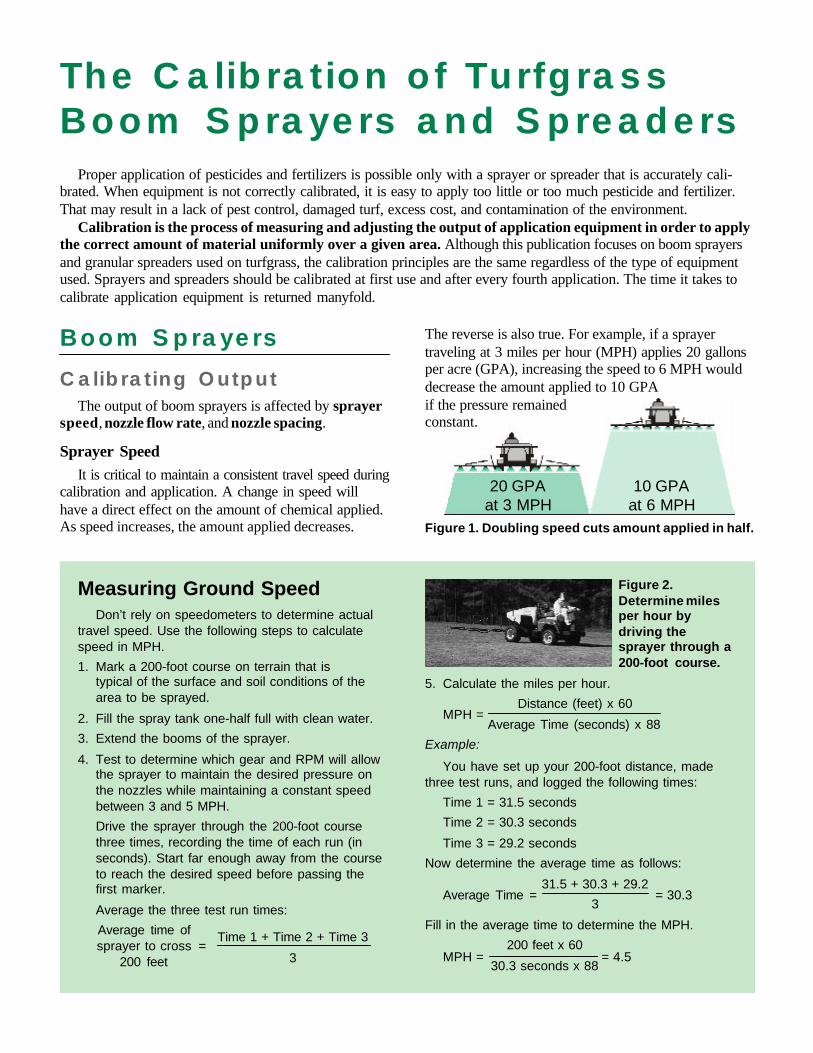
5. Calculate the miles per hour.
Distance (feet) x 60
Average Time (seconds) x 88
Example:
You have set up your 200-foot distance, madethree test runs, and logged the following times:
Time 1 = 31.5 seconds
Time 2 = 30.3 seconds
Time 3 = 29.2 seconds
Now determine the average time as follows:
31.5 + 30.3 + 29.2
3
Fill in the average time to determine the MPH.
200 feet x 60
30.3 seconds x 88
Boom Sprayers
Calibrating OutputThe output of boom sprayers is affected by sprayer
speed, nozzle flow rate, and nozzle spacing.
Sprayer SpeedIt is critical to maintain a consistent travel speed during
calibration and application. A change in speed willhave a direct effect on the amount of chemical applied.As speed increases, the amount applied decreases.
The Calibration of TurfgrassBoom Sprayers and Spreaders
Proper application of pesticides and fertilizers is possible only with a sprayer or spreader that is accurately cali-brated. When equipment is not correctly calibrated, it is easy to apply too little or too much pesticide and fertilizer.That may result in a lack of pest control, damaged turf, excess cost, and contamination of the environment.
Calibration is the process of measuring and adjusting the output of application equipment in order to applythe correct amount of material uniformly over a given area. Although this publication focuses on boom sprayersand granular spreaders used on turfgrass, the calibration principles are the same regardless of the type of equipmentused. Sprayers and spreaders should be calibrated at first use and after every fourth application. The time it takes tocalibrate application equipment is returned manyfold.
20 GPA 10 GPAat 3 MPH at 6 MPH
Figure 1. Doubling speed cuts amount applied in half.
The reverse is also true. For example, if a sprayertraveling at 3 miles per hour (MPH) applies 20 gallonsper acre (GPA), increasing the speed to 6 MPH woulddecrease the amount applied to 10 GPAif the pressure remainedconstant.
Measuring Ground SpeedDon’t rely on speedometers to determine actual
travel speed. Use the following steps to calculatespeed in MPH.
1. Mark a 200-foot course on terrain that istypical of the surface and soil conditions of thearea to be sprayed.
2. Fill the spray tank one-half full with clean water.
3. Extend the booms of the sprayer.
4. Test to determine which gear and RPM will allowthe sprayer to maintain the desired pressure onthe nozzles while maintaining a constant speedbetween 3 and 5 MPH.
Drive the sprayer through the 200-foot coursethree times, recording the time of each run (inseconds). Start far enough away from the courseto reach the desired speed before passing thefirst marker.
Average the three test run times:
Average time ofsprayer to cross =
200 feet
Time 1 + Time 2 + Time 3
3
Figure 2.Determine milesper hour bydriving thesprayer through a200-foot course.
MPH =
Average Time = = 30.3
MPH = = 4.5
The Calibration of Turfgrass Boom Sprayers and Spreaders
4
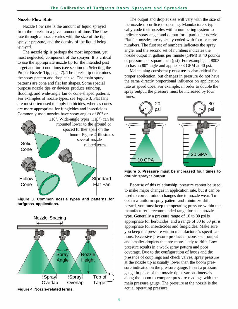
The output and droplet size will vary with the size ofthe nozzle tip orifice or opening. Manufacturers typi-cally code their nozzles with a numbering system toindicate spray angle and output for a particular nozzle.Flat fan nozzles are typically coded with four or morenumbers. The first set of numbers indicates the sprayangle, and the second set of numbers indicates thenozzle output in gallons per minute (GPM) at 40 poundsof pressure per square inch (psi). For example, an 8003tip has an 80° angle and applies 0.3 GPM at 40 psi.
Maintaining consistent pressure is also critical forproper application, but changes in pressure do not havethe same directly proportional influence on applicationrate as speed does. For example, in order to double thespray output, the pressure must be increased by fourtimes.
Because of this relationship, pressure cannot be usedto make major changes in application rate, but it can beused to correct minor changes due to nozzle wear. Toobtain a uniform spray pattern and minimize drifthazard, you must keep the operating pressure within themanufacturer’s recommended range for each nozzletype. Generally a pressure range of 10 to 30 psi isappropriate for herbicides, and a range of 30 to 50 psi isappropriate for insecticides and fungicides. Make sureyou keep the pressure within manufacturer’s specifica-tions. Excessive pressure produces inconsistent outputand smaller droplets that are more likely to drift. Lowpressure results in a weak spray pattern and poorcoverage. Due to the configuration of hoses and thepresence of couplings and check valves, spray pressureat the nozzle tip is usually lower than the boom pres-sure indicated on the pressure gauge. Insert a pressuregauge in place of the nozzle tip at various intervalsalong the boom to compare pressure readings with themain pressure gauge. The pressure at the nozzle is theactual operating pressure.
Nozzle Spacing
Spray NozzleAngle Height
Spray Spray Top ofOverlap Overlap Target
Figure 4. Nozzle-related terms.
20 80psi psi
20 GPA10 GPA
Figure 5. Pressure must be increased four times todouble sprayer output.
Nozzle Flow RateNozzle flow rate is the amount of liquid sprayed
from the nozzle in a given amount of time. The flowrate through a nozzle varies with the size of the tip,sprayer pressure, and the density of the liquid beingsprayed.
The nozzle tip is perhaps the most important, yetmost neglected, component of the sprayer. It is criticalto use the appropriate nozzle tip for the intended pesttarget and turf conditions (see section on Selecting theProper Nozzle Tip, page 7). The nozzle tip determinesthe spray pattern and droplet size. The main spraypatterns are cone and flat fan shapes. Some specialpurpose nozzle tips or devices produce raindrop,flooding, and wide-angle fan or cone-shaped patterns.For examples of nozzle types, see Figure 3. Flat fansare most often used to apply herbicides, whereas conesare more appropriate for fungicides and insecticides.Commonly used nozzles have spray angles of 80° or
110°. Wide-angle types (110°) can bemounted lower to the ground or
spaced further apart on theboom. Figure 4 illustrates
several nozzle-related terms.Solid
Cone
Hollow StandardCone Flat Fan
Figure 3. Common nozzle types and patterns forturfgrass applications.
The Calibration of Turfgrass Boom Sprayers and Spreaders
5
The density of a liquid is determined by its weight(pounds) per gallon. Density affects the rate at which aliquid will flow and thereby affects its output from asprayer. Typically, the procedures used to calibrate asprayer or select a nozzle tip are based on using cleanwater. Spraying solutions other than water, such asliquid fertilizer, may affect the nozzle flow rate becausefertilizer is more dense than water. Nozzle manufactur-ers’ catalogs contain conversion tables to help youchoose the correct size nozzle or to convert sprayeroutput. The conversion factors are based on the specificgravity of the liquid, a factor that relates the density ofthe liquid to water, which weighs 8.34 pounds pergallon. You may find it more convenient to conduct thecalibration using the liquid fertilizer instead of water,but make certain to wear the proper protective equip-ment when using active ingredients. (If the fertilizerwill be diluted in water, use water for the calibrationtest.)
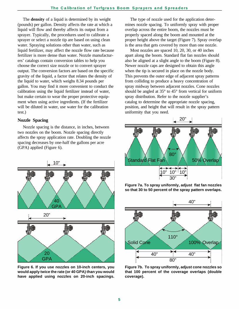
Nozzle SpacingNozzle spacing is the distance, in inches, between
two nozzles on the boom. Nozzle spacing directlyaffects the spray application rate. Doubling the nozzlespacing decreases by one-half the gallons per acre(GPA) applied (Figure 6).
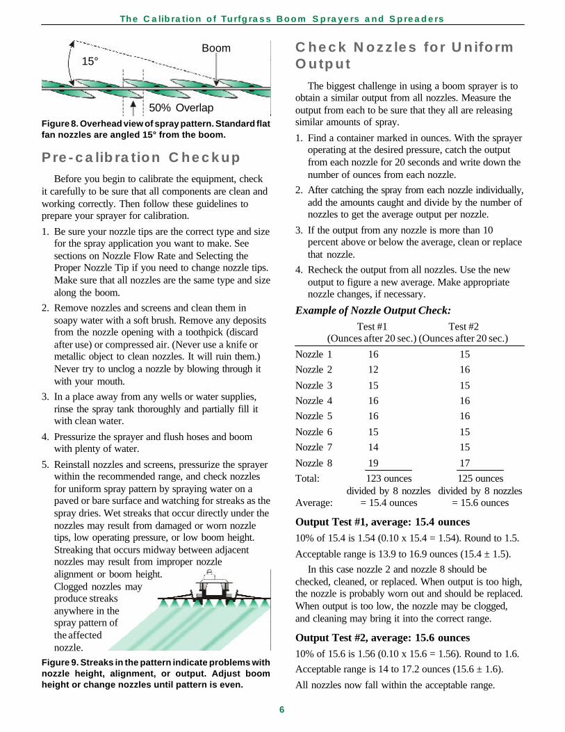
The type of nozzle used for the application deter-mines nozzle spacing. To uniformly spray with properoverlap across the entire boom, the nozzles must beproperly spaced along the boom and mounted at theproper height above the target (Figure 7). Spray overlapis the area that gets covered by more than one nozzle.
Most nozzles are spaced 10, 20, 30, or 40 inchesapart along the boom. Standard flat fan nozzles shouldalso be aligned at a slight angle to the boom (Figure 8).Newer nozzle caps are designed to obtain this anglewhen the tip is secured in place on the nozzle body.This prevents the outer edge of adjacent spray patternsfrom colliding to produce a heavy concentration ofspray midway between adjacent nozzles. Cone nozzlesshould be angled at 35° to 45° from vertical for uniformspray distribution. Refer to the nozzle supplier’scatalog to determine the appropriate nozzle spacing,position, and height that will result in the spray patternuniformity that you need.
10"
40GPA
20"
20GPA
Figure 6. If you use nozzles on 10-inch centers, youwould apply twice the rate (or 40 GPA) than you wouldhave applied using nozzles on 20-inch spacings.
20"
80°Standard Flat Fan 50% Overlap
10" 10" 10"30"
Figure 7a. To spray uniformly, adjust flat fan nozzlesso that 30 to 50 percent of the spray pattern overlaps.
40"
110°Solid Cone 100% Overlap
40" 40"80"
Figure 7b. To spray uniformly, adjust cone nozzles sothat 100 percent of the coverage overlaps (doublecoverage).
The Calibration of Turfgrass Boom Sprayers and Spreaders
6
Pre-calibration CheckupBefore you begin to calibrate the equipment, check
it carefully to be sure that all components are clean andworking correctly. Then follow these guidelines toprepare your sprayer for calibration.
1. Be sure your nozzle tips are the correct type and sizefor the spray application you want to make. Seesections on Nozzle Flow Rate and Selecting theProper Nozzle Tip if you need to change nozzle tips.Make sure that all nozzles are the same type and sizealong the boom.
2. Remove nozzles and screens and clean them insoapy water with a soft brush. Remove any depositsfrom the nozzle opening with a toothpick (discardafter use) or compressed air. (Never use a knife ormetallic object to clean nozzles. It will ruin them.)Never try to unclog a nozzle by blowing through itwith your mouth.
3. In a place away from any wells or water supplies,rinse the spray tank thoroughly and partially fill itwith clean water.
4. Pressurize the sprayer and flush hoses and boomwith plenty of water.
5. Reinstall nozzles and screens, pressurize the sprayerwithin the recommended range, and check nozzlesfor uniform spray pattern by spraying water on apaved or bare surface and watching for streaks as thespray dries. Wet streaks that occur directly under thenozzles may result from damaged or worn nozzletips, low operating pressure, or low boom height.Streaking that occurs midway between adjacentnozzles may result from improper nozzlealignment or boom height.Clogged nozzles mayproduce streaksanywhere in thespray pattern ofthe affectednozzle.
Figure 9. Streaks in the pattern indicate problems withnozzle height, alignment, or output. Adjust boomheight or change nozzles until pattern is even.
Check Nozzles for UniformOutput
The biggest challenge in using a boom sprayer is toobtain a similar output from all nozzles. Measure theoutput from each to be sure that they all are releasingsimilar amounts of spray.
1. Find a container marked in ounces. With the sprayeroperating at the desired pressure, catch the outputfrom each nozzle for 20 seconds and write down thenumber of ounces from each nozzle.
2. After catching the spray from each nozzle individually,add the amounts caught and divide by the number ofnozzles to get the average output per nozzle.
3. If the output from any nozzle is more than 10percent above or below the average, clean or replacethat nozzle.
4. Recheck the output from all nozzles. Use the newoutput to figure a new average. Make appropriatenozzle changes, if necessary.
Example of Nozzle Output Check:
Test #1 Test #2(Ounces after 20 sec.) (Ounces after 20 sec.)
Nozzle 1 16 15
Nozzle 2 12 16
Nozzle 3 15 15
Nozzle 4 16 16
Nozzle 5 16 16
Nozzle 6 15 15
Nozzle 7 14 15
Nozzle 8 19 17
Total: 123 ounces 125 ouncesdivided by 8 nozzles divided by 8 nozzles
Average: = 15.4 ounces = 15.6 ounces
Output Test #1, average: 15.4 ounces10% of 15.4 is 1.54 (0.10 x 15.4 = 1.54). Round to 1.5.
Acceptable range is 13.9 to 16.9 ounces (15.4 ± 1.5).
In this case nozzle 2 and nozzle 8 should bechecked, cleaned, or replaced. When output is too high,the nozzle is probably worn out and should be replaced.When output is too low, the nozzle may be clogged,and cleaning may bring it into the correct range.
Output Test #2, average: 15.6 ounces10% of 15.6 is 1.56 (0.10 x 15.6 = 1.56). Round to 1.6.
Acceptable range is 14 to 17.2 ounces (15.6 ± 1.6).
All nozzles now fall within the acceptable range.
Boom15°
50% OverlapFigure 8. Overhead view of spray pattern. Standard flatfan nozzles are angled 15° from the boom.
The Calibration of Turfgrass Boom Sprayers and Spreaders
7
Selecting the Proper Nozzle Tip
The nozzle type and size must be carefullychosen for each particular treatment.
Selection of the appropriate nozzle type is basedprimarily upon the target pest. In general, flat fansare more appropriate for weed control, and conetypes are better for insects and diseases. However,there are exceptions when considering the activity ofthe pesticide. For example, flat fans are better forspraying contact insecticides, whereas cones arebetter for applying systemic insecticides. Nozzlesuppliers’ catalogs have information to assist youwith this decision.
The size of the nozzle tip will depend upon theapplication rate in gallons per acre (GPA), groundspeed in miles per hour (MPH), and effectivesprayed width (W) or number of inches betweennozzles on the boom. GPA, MPH, and W are used todetermine the gallons per minute (GPM) required foreach nozzle to provide the desired flow rate. Byfollowing these five steps, you can select the nozzlesrequired for each application.
1. Refer to the pesticide or fertilizer label for therecommended spray application rate in gallonsper acre (GPA) for your situation. The sprayapplication rate is the gallons of carrier (water,fertilizer, etc.) and pesticide (or fertilizer) appliedper acre. When using a carrier other than water,multiply the desired GPA by a conversion factorlisted in the nozzle supplier’s catalog and use thatvalue for GPA in Step 4 below.
2. Follow the steps in the section on MeasuringGround Speed (page 3) to determine your actualspeed in miles per hour (MPH) under fieldconditions.
3. Determine the effective sprayed width (W) pernozzle in inches. Measure the distance betweentwo nozzles, center to center, on the boom.
4. Determine the flow required from each nozzle ingallons per minute (GPM) by inserting the valuesdetermined in Steps 1 through 3 into the followingequation:
GPA x MPH x W
5,940
5. Refer to a nozzle supplier’s catalog to select thenozzle size that will give the desired outputdetermined in Step 4 at the speed and pressureyou intend to use.
Example:
You want to apply a herbicide at 15 GPA, at aspeed of 5 mph, using flat fan nozzles spaced 20inches apart on the boom. What nozzle tip shouldyou select? The required flow rate from each nozzleis as follows:
15 x 5 x 20 1,500
5,940 5,940
The nozzle that you select must have a flow rateat 0.25 GPM when operated within a desiredpressure range.
When selecting a nozzle tip, it is important toconsider the potential for spray drift. A nozzle’s spraypattern is made up of numerous spray droplets ofvarying sizes. The key to reducing drift is to reducethe number of fine particles, or small-sized droplets,within the spray volume while still maintaining yourspray pattern for even coverage. Special features, orsubtypes like “extended range,” are available forsome nozzle types that produce a greaterpercentage of large droplet sizes over a wide rangeof pressures.
Referring to a chart of flat fan nozzle tips in theSpraying Systems Co. catalog, we find that theTP8003 (flat fan spray tips) produces 0.26 GPM at30 psi and thereby provides the correct output.However, an XR8004 Extended Range flat spray tipoperated at a more desirable pressure range of 15 to20 psi would achieve the correct output whileminimizing the risk of drift.
After choosing the right nozzles, make sure thatthey are set at the correct spacing, height above thetarget, and orientation on the boom.
GPM (per nozzle) =
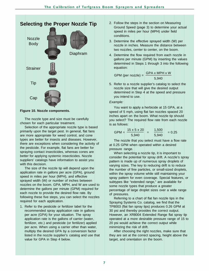
NozzleBody
Diaphram
Strainer
Tip
Cap
Figure 10. Nozzle components.
GPM = = = 0.25
The Calibration of Turfgrass Boom Sprayers and Spreaders
8
Measuring Output nozzles as described in Step 7 above to determinethe nozzle flow rate in ounces per minute (OPM).
2. Convert OPM (Step 1) to GPM. Divide OPM by128.
3. Determine sprayer speed (MPH) as described above.
4. Measure nozzle spacing (W) as described above.
5. Determine sprayer output in gallons per acre (GPA)by inserting the values determined in Steps 2through 4 into the following equation:
GPM x 5940
MPH x W
To determine the equivalent gallons per 1,000square feet, divide the GPA by 43.56.
Example:
The average nozzle output from your boom sprayeris 44 OPM or 0.34 GPM (44/128). The sprayer speed is4.5 MPH and nozzles are spaced 20 inches apart on theboom. What is the sprayer output in gallons per acre?What is the output in gallons per 1,000 sq. ft.?
0.34 x 5,940
4.5 x 20
22.4 GPA
43.56
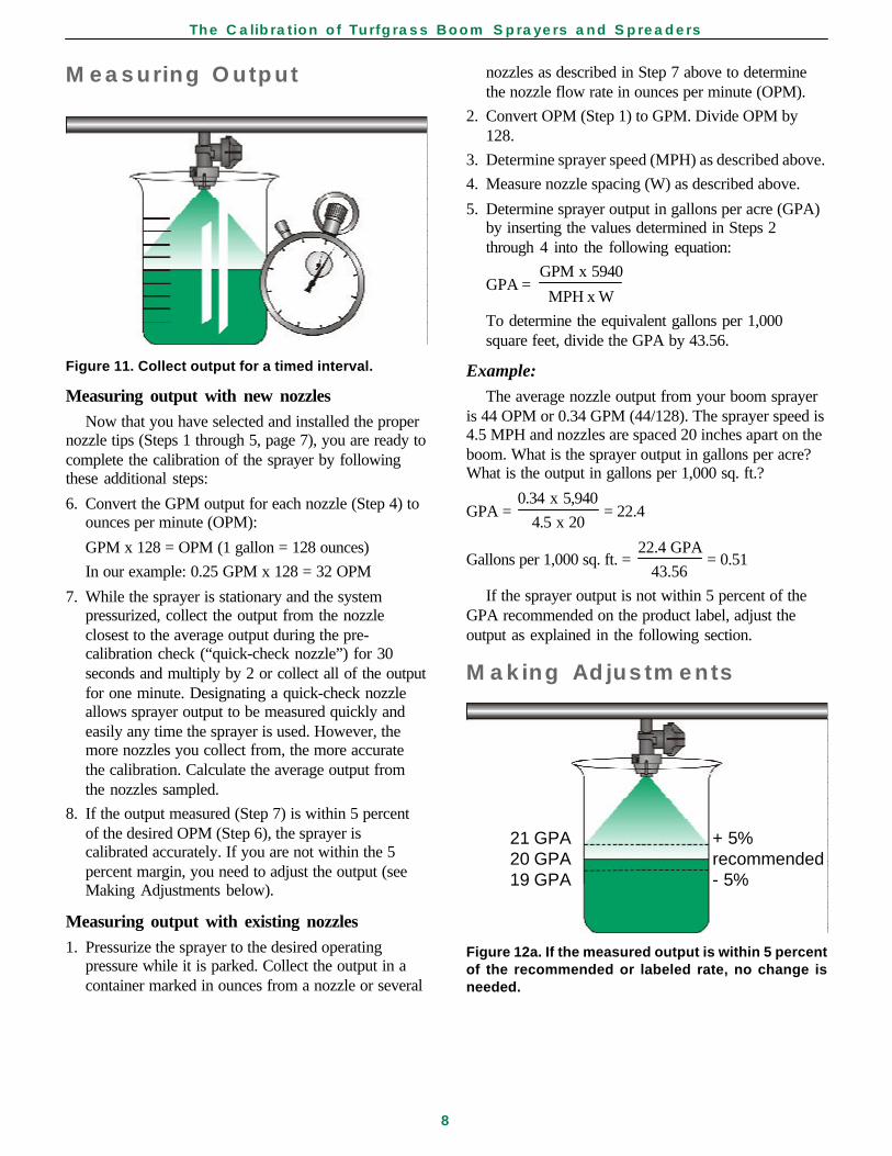
If the sprayer output is not within 5 percent of theGPA recommended on the product label, adjust theoutput as explained in the following section.
Making Adjustments
GPA = = 22.4
Gallons per 1,000 sq. ft. = = 0.51
21 GPA + 5%20 GPA recommended19 GPA - 5%
Figure 12a. If the measured output is within 5 percentof the recommended or labeled rate, no change isneeded.
Figure 11. Collect output for a timed interval.
Measuring output with new nozzlesNow that you have selected and installed the proper
nozzle tips (Steps 1 through 5, page 7), you are ready tocomplete the calibration of the sprayer by followingthese additional steps:
6. Convert the GPM output for each nozzle (Step 4) toounces per minute (OPM):
GPM x 128 = OPM (1 gallon = 128 ounces)
In our example: 0.25 GPM x 128 = 32 OPM
7. While the sprayer is stationary and the systempressurized, collect the output from the nozzleclosest to the average output during the pre-calibration check (“quick-check nozzle”) for 30seconds and multiply by 2 or collect all of the outputfor one minute. Designating a quick-check nozzleallows sprayer output to be measured quickly andeasily any time the sprayer is used. However, themore nozzles you collect from, the more accuratethe calibration. Calculate the average output fromthe nozzles sampled.
8. If the output measured (Step 7) is within 5 percentof the desired OPM (Step 6), the sprayer iscalibrated accurately. If you are not within the 5percent margin, you need to adjust the output (seeMaking Adjustments below).
Measuring output with existing nozzles1. Pressurize the sprayer to the desired operating
pressure while it is parked. Collect the output in acontainer marked in ounces from a nozzle or several
GPA =
The Calibration of Turfgrass Boom Sprayers and Spreaders
9
21–22 GPA + 5–10%
20 GPA recommended
18–19 GPA - 5–10%
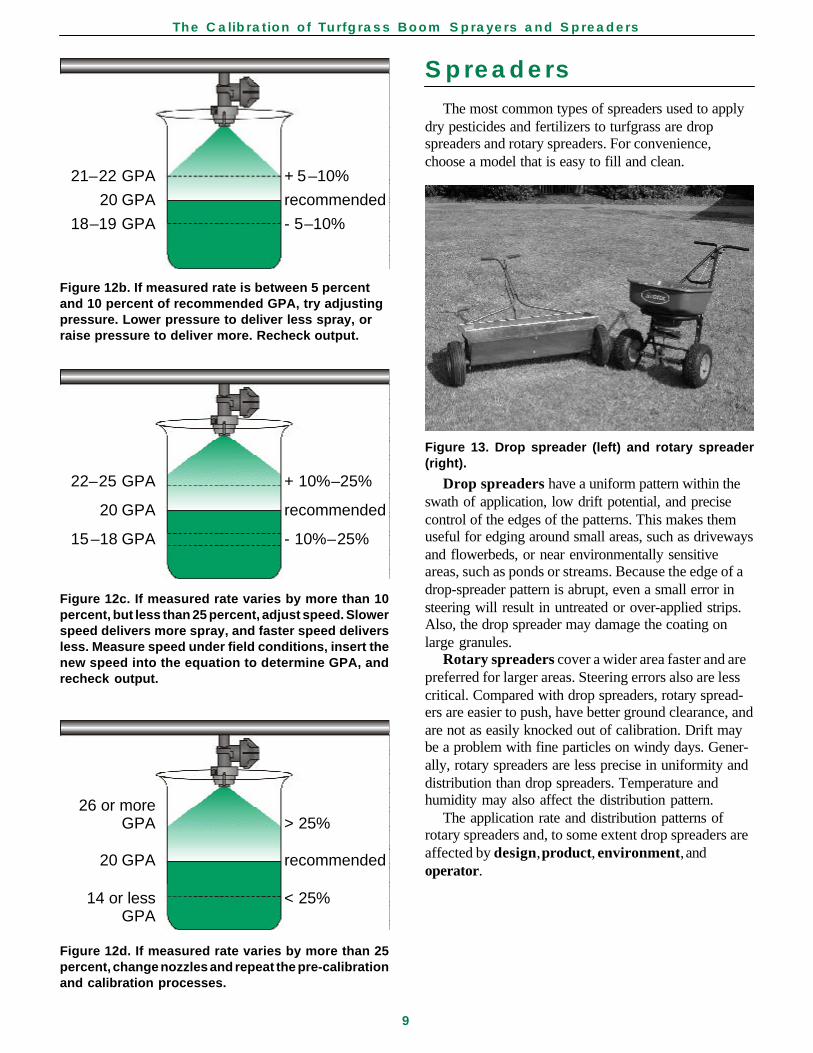
Figure 12b. If measured rate is between 5 percentand 10 percent of recommended GPA, try adjustingpressure. Lower pressure to deliver less spray, orraise pressure to deliver more. Recheck output.
22–25 GPA + 10%–25%
20 GPA recommended
15–18 GPA - 10%–25%
Figure 12c. If measured rate varies by more than 10percent, but less than 25 percent, adjust speed. Slowerspeed delivers more spray, and faster speed deliversless. Measure speed under field conditions, insert thenew speed into the equation to determine GPA, andrecheck output.
Spreaders
The most common types of spreaders used to applydry pesticides and fertilizers to turfgrass are dropspreaders and rotary spreaders. For convenience,choose a model that is easy to fill and clean.
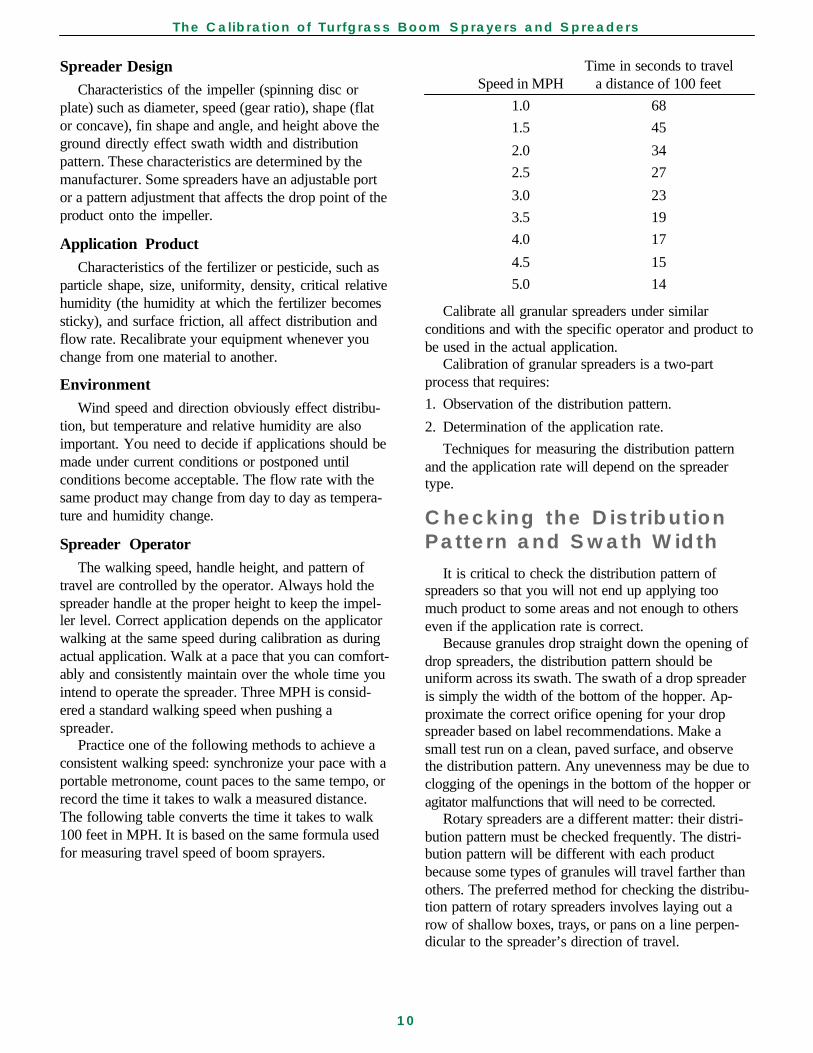
Figure 13. Drop spreader (left) and rotary spreader(right).
Drop spreaders have a uniform pattern within theswath of application, low drift potential, and precisecontrol of the edges of the patterns. This makes themuseful for edging around small areas, such as drivewaysand flowerbeds, or near environmentally sensitiveareas, such as ponds or streams. Because the edge of adrop-spreader pattern is abrupt, even a small error insteering will result in untreated or over-applied strips.Also, the drop spreader may damage the coating onlarge granules.
Rotary spreaders cover a wider area faster and arepreferred for larger areas. Steering errors also are lesscritical. Compared with drop spreaders, rotary spread-ers are easier to push, have better ground clearance, andare not as easily knocked out of calibration. Drift maybe a problem with fine particles on windy days. Gener-ally, rotary spreaders are less precise in uniformity anddistribution than drop spreaders. Temperature andhumidity may also affect the distribution pattern.
The application rate and distribution patterns ofrotary spreaders and, to some extent drop spreaders areaffected by design, product, environment, andoperator.
26 or moreGPA > 25%
20 GPA recommended
14 or less < 25%GPA
Figure 12d. If measured rate varies by more than 25percent, change nozzles and repeat the pre-calibrationand calibration processes.
The Calibration of Turfgrass Boom Sprayers and Spreaders
10
Spreader DesignCharacteristics of the impeller (spinning disc or
plate) such as diameter, speed (gear ratio), shape (flator concave), fin shape and angle, and height above theground directly effect swath width and distributionpattern. These characteristics are determined by themanufacturer. Some spreaders have an adjustable portor a pattern adjustment that affects the drop point of theproduct onto the impeller.
Application ProductCharacteristics of the fertilizer or pesticide, such as
particle shape, size, uniformity, density, critical relativehumidity (the humidity at which the fertilizer becomessticky), and surface friction, all affect distribution andflow rate. Recalibrate your equipment whenever youchange from one material to another.
EnvironmentWind speed and direction obviously effect distribu-
tion, but temperature and relative humidity are alsoimportant. You need to decide if applications should bemade under current conditions or postponed untilconditions become acceptable. The flow rate with thesame product may change from day to day as tempera-ture and humidity change.
Spreader OperatorThe walking speed, handle height, and pattern of
travel are controlled by the operator. Always hold thespreader handle at the proper height to keep the impel-ler level. Correct application depends on the applicatorwalking at the same speed during calibration as duringactual application. Walk at a pace that you can comfort-ably and consistently maintain over the whole time youintend to operate the spreader. Three MPH is consid-ered a standard walking speed when pushing aspreader.
Practice one of the following methods to achieve aconsistent walking speed: synchronize your pace with aportable metronome, count paces to the same tempo, orrecord the time it takes to walk a measured distance.The following table converts the time it takes to walk100 feet in MPH. It is based on the same formula usedfor measuring travel speed of boom sprayers.
Time in seconds to travelSpeed in MPH a distance of 100 feet
1.0 68
1.5 45
2.0 34
2.5 27
3.0 23
3.5 19
4.0 17
4.5 15
5.0 14
Calibrate all granular spreaders under similarconditions and with the specific operator and product tobe used in the actual application.
Calibration of granular spreaders is a two-partprocess that requires:
1. Observation of the distribution pattern.
2. Determination of the application rate.
Techniques for measuring the distribution patternand the application rate will depend on the spreadertype.
Checking the DistributionPattern and Swath Width
It is critical to check the distribution pattern ofspreaders so that you will not end up applying toomuch product to some areas and not enough to otherseven if the application rate is correct.
Because granules drop straight down the opening ofdrop spreaders, the distribution pattern should beuniform across its swath. The swath of a drop spreaderis simply the width of the bottom of the hopper. Ap-proximate the correct orifice opening for your dropspreader based on label recommendations. Make asmall test run on a clean, paved surface, and observethe distribution pattern. Any unevenness may be due toclogging of the openings in the bottom of the hopper oragitator malfunctions that will need to be corrected.
Rotary spreaders are a different matter: their distri-bution pattern must be checked frequently. The distri-bution pattern will be different with each productbecause some types of granules will travel farther thanothers. The preferred method for checking the distribu-tion pattern of rotary spreaders involves laying out arow of shallow boxes, trays, or pans on a line perpen-dicular to the spreader’s direction of travel.
The Calibration of Turfgrass Boom Sprayers and Spreaders
11
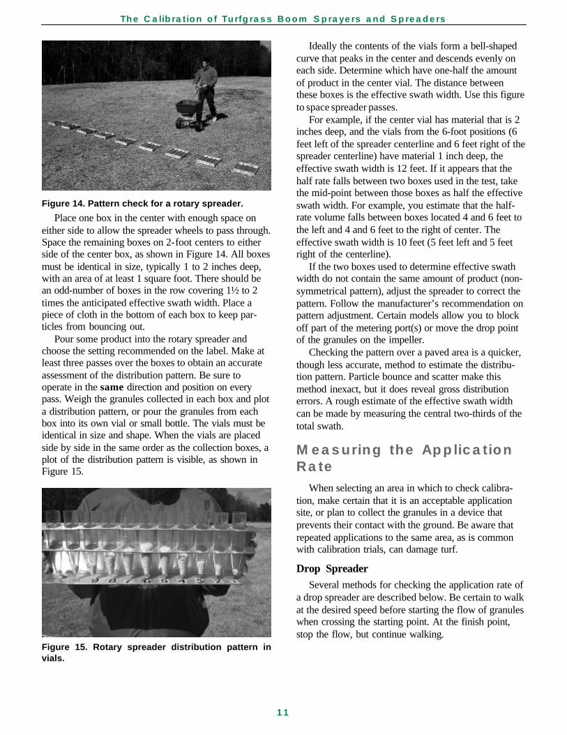
Figure 14. Pattern check for a rotary spreader.
Place one box in the center with enough space oneither side to allow the spreader wheels to pass through.Space the remaining boxes on 2-foot centers to eitherside of the center box, as shown in Figure 14. All boxesmust be identical in size, typically 1 to 2 inches deep,with an area of at least 1 square foot. There should bean odd-number of boxes in the row covering 1½ to 2times the anticipated effective swath width. Place apiece of cloth in the bottom of each box to keep par-ticles from bouncing out.
Pour some product into the rotary spreader andchoose the setting recommended on the label. Make atleast three passes over the boxes to obtain an accurateassessment of the distribution pattern. Be sure tooperate in the same direction and position on everypass. Weigh the granules collected in each box and plota distribution pattern, or pour the granules from eachbox into its own vial or small bottle. The vials must beidentical in size and shape. When the vials are placedside by side in the same order as the collection boxes, aplot of the distribution pattern is visible, as shown inFigure 15.
Figure 15. Rotary spreader distribution pattern invials.
Ideally the contents of the vials form a bell-shapedcurve that peaks in the center and descends evenly oneach side. Determine which have one-half the amountof product in the center vial. The distance betweenthese boxes is the effective swath width. Use this figureto space spreader passes.
For example, if the center vial has material that is 2inches deep, and the vials from the 6-foot positions (6feet left of the spreader centerline and 6 feet right of thespreader centerline) have material 1 inch deep, theeffective swath width is 12 feet. If it appears that thehalf rate falls between two boxes used in the test, takethe mid-point between those boxes as half the effectiveswath width. For example, you estimate that the half-rate volume falls between boxes located 4 and 6 feet tothe left and 4 and 6 feet to the right of center. Theeffective swath width is 10 feet (5 feet left and 5 feetright of the centerline).
If the two boxes used to determine effective swathwidth do not contain the same amount of product (non-symmetrical pattern), adjust the spreader to correct thepattern. Follow the manufacturer’s recommendation onpattern adjustment. Certain models allow you to blockoff part of the metering port(s) or move the drop pointof the granules on the impeller.
Checking the pattern over a paved area is a quicker,though less accurate, method to estimate the distribu-tion pattern. Particle bounce and scatter make thismethod inexact, but it does reveal gross distributionerrors. A rough estimate of the effective swath widthcan be made by measuring the central two-thirds of thetotal swath.
Measuring the ApplicationRate
When selecting an area in which to check calibra-tion, make certain that it is an acceptable applicationsite, or plan to collect the granules in a device thatprevents their contact with the ground. Be aware thatrepeated applications to the same area, as is commonwith calibration trials, can damage turf.
Drop SpreaderSeveral methods for checking the application rate of
a drop spreader are described below. Be certain to walkat the desired speed before starting the flow of granuleswhen crossing the starting point. At the finish point,stop the flow, but continue walking.
The Calibration of Turfgrass Boom Sprayers and Spreaders
12
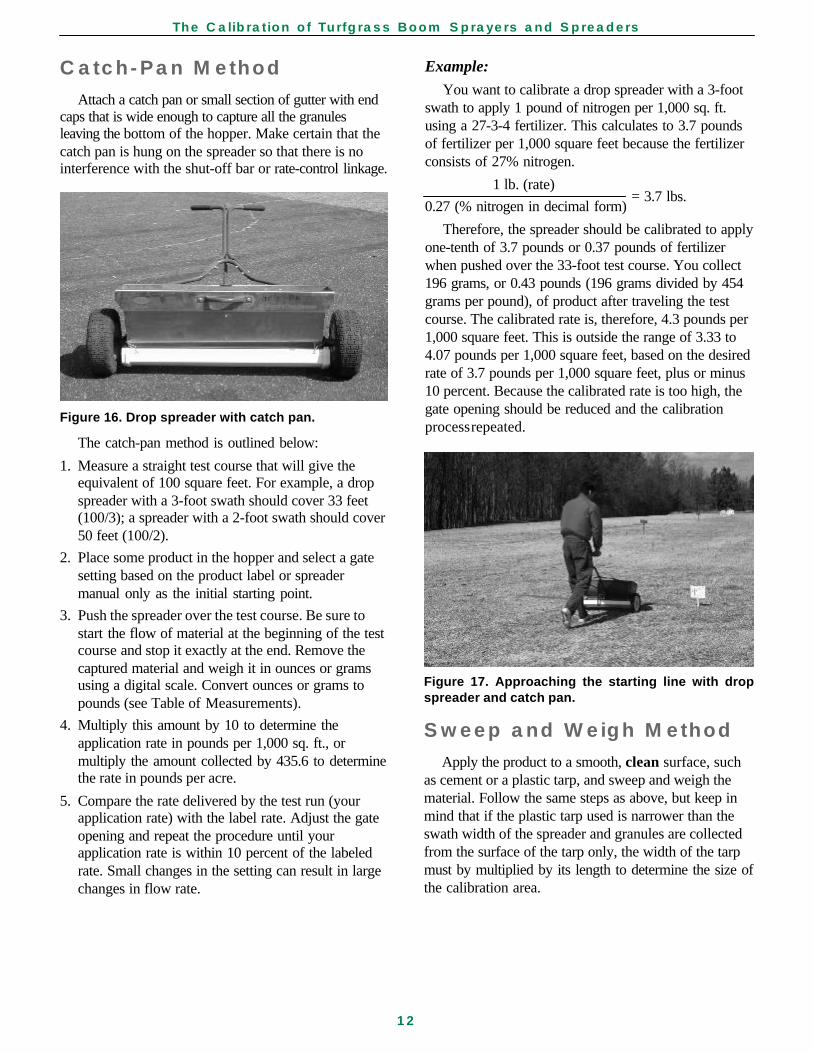
Catch-Pan Method
Attach a catch pan or small section of gutter with endcaps that is wide enough to capture all the granulesleaving the bottom of the hopper. Make certain that thecatch pan is hung on the spreader so that there is nointerference with the shut-off bar or rate-control linkage.
Figure 16. Drop spreader with catch pan.
The catch-pan method is outlined below:
1. Measure a straight test course that will give theequivalent of 100 square feet. For example, a dropspreader with a 3-foot swath should cover 33 feet(100/3); a spreader with a 2-foot swath should cover50 feet (100/2).
2. Place some product in the hopper and select a gatesetting based on the product label or spreadermanual only as the initial starting point.
3. Push the spreader over the test course. Be sure tostart the flow of material at the beginning of the testcourse and stop it exactly at the end. Remove thecaptured material and weigh it in ounces or gramsusing a digital scale. Convert ounces or grams topounds (see Table of Measurements).
4. Multiply this amount by 10 to determine theapplication rate in pounds per 1,000 sq. ft., ormultiply the amount collected by 435.6 to determinethe rate in pounds per acre.
5. Compare the rate delivered by the test run (yourapplication rate) with the label rate. Adjust the gateopening and repeat the procedure until yourapplication rate is within 10 percent of the labeledrate. Small changes in the setting can result in largechanges in flow rate.
Figure 17. Approaching the starting line with dropspreader and catch pan.
Sweep and Weigh Method
Apply the product to a smooth, clean surface, suchas cement or a plastic tarp, and sweep and weigh thematerial. Follow the same steps as above, but keep inmind that if the plastic tarp used is narrower than theswath width of the spreader and granules are collectedfrom the surface of the tarp only, the width of the tarpmust by multiplied by its length to determine the size ofthe calibration area.
Example:
You want to calibrate a drop spreader with a 3-footswath to apply 1 pound of nitrogen per 1,000 sq. ft.using a 27-3-4 fertilizer. This calculates to 3.7 poundsof fertilizer per 1,000 square feet because the fertilizerconsists of 27% nitrogen.
1 lb. (rate)
0.27 (% nitrogen in decimal form)
Therefore, the spreader should be calibrated to applyone-tenth of 3.7 pounds or 0.37 pounds of fertilizerwhen pushed over the 33-foot test course. You collect196 grams, or 0.43 pounds (196 grams divided by 454grams per pound), of product after traveling the testcourse. The calibrated rate is, therefore, 4.3 pounds per1,000 square feet. This is outside the range of 3.33 to4.07 pounds per 1,000 square feet, based on the desiredrate of 3.7 pounds per 1,000 square feet, plus or minus10 percent. Because the calibrated rate is too high, thegate opening should be reduced and the calibrationprocess repeated.
= 3.7 lbs.
The Calibration of Turfgrass Boom Sprayers and Spreaders
13
Weigh Before and AfterMethods
You can also determine the amount of materialapplied by taking before and after weights:
1. Place a known weight of granules in the hopper,conduct a trial run, and reweigh the granulesremaining in the spreader.
2. If a large scale is available, determine the amountapplied by weighing before and after the application.The difference in weight is the amount of granulesapplied to the calibration area.
Example:
You put 2 pounds of granules in a drop spreader thathas a swath width of 2 feet. After applying the productto a 50-foot test course, you recover 1.75 pounds ofgranules from the spreader. The calibrated rate is 0.25pounds per 100 square feet, or 2.5 pounds per 1,000square feet.
Rotary SpreaderTo ensure uniform coverage with a rotary spreader,
apply the product at half the labeled rate in two passesover the area. This is especially important if the distri-bution pattern is not symmetrical. The goal for calibrat-ing a rotary spreader, therefore, is to verify an applica-tion rate that is within 10 percent of one-half thelabeled rate.
Collection devices can be used to calibrate a rotaryspreader. However, commercially available shroudsthat are attached to the spreader are compatible onlywith a limited number of spreader makes and models.Other devices like plastic bags secured to the bottom ofthe spreader can interfere with product delivery andcause inaccurate results. Determine the effective swathwidth before attempting to calibrate a rotary spreaderwith a collection device.
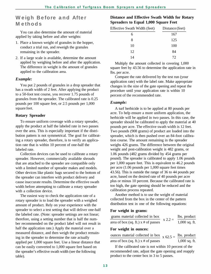
The easiest way to check the application rate of arotary spreader is to load the spreader with a weighedamount of product. Rely on your experience with thespreader to select a test setting that will deliver one-halfthe labeled rate. (Note: spreader settings are not linear;therefore, using a setting number that is half the num-ber recommended on the product label will not result inhalf the application rate.) Apply the material over ameasured distance, and then weigh the product remain-ing in the spreader to determine the rate actuallyapplied per 1,000 square feet. Use a linear distance thatcan be easily converted to 1,000 square feet based onthe spreader’s effective swath width (see the followingtable).
Distance and Effective Swath Width for RotarySpreaders to Equal 1,000 Square FeetEffective Swath Width (feet) Distance (feet)
6 167
8 125
10 100
12 84
14 72
Multiply the amount collected in covering 1,000square feet by 43.56 to determine the application rate inlbs. per acre.
Compare the rate delivered by the test run (yourapplication rate) with the label rate. Make appropriatechanges in the size of the gate opening and repeat theprocedure until your application rate is within 10percent of the recommended rate.
Example:
A turf herbicide is to be applied at 80 pounds peracre. To help ensure a more uniform application, theherbicide will be applied in two passes. In this case, thespreader should be calibrated to apply the material at 40pounds per acre. The effective swath width is 12 feet.Two pounds (908 grams) of product are loaded into thespreader, which is then pushed over an 84-foot calibra-tion course. The amount remaining in the spreaderweighs 426 grams. The difference between the originalweight and post-calibration weight is 482 grams, or1.06 pounds (482 grams divided by 454 grams perpound). The spreader is calibrated to apply 1.06 poundsper 1,000 square feet. This is equivalent to 46.2 poundsper acre (1.06 pounds per 1,000 square feet times43.56). This is outside the range of 36 to 44 pounds peracre, based on the desired rate of 40 pounds per acreplus or minus 10 percent. Because the calibrated rate istoo high, the gate opening should be reduced and thecalibration process repeated.
Another method is to use the weight of materialcollected from the box in the center of the patterndistribution test in one of the following equations:
For weight in grams:grams material collected in box lbs. product
area of box (sq. ft.) x # of passes 1,000 sq. ft.
For weight in ounces:ounces material collected in box lbs. product
area of box (sq. ft.) x # of passes 1,000 sq. ft.
If the calibrated rate is not within 10 percent of therecommended rate, adjust the gate opening and reapplyproduct to the center box in 3 to 5 passes.
x 2.2 =
x 62.5 =
The Calibration of Turfgrass Boom Sprayers and Spreaders
14
Determining How Much toApply
After calibrating the spreader, determining theamount of product required for the application isstraightforward. Use a measuring wheel or tape toaccurately measure the area to be treated. Label appli-cation rates typically are provided in pounds of productper acre or per 1,000 square feet. Whether you useacres or 1,000 square feet in your calculations, beconsistent. Divide square feet by 43,560 to convert toacres; multiply acres by 43,560 to convert to squarefeet. To determine the amount of product to apply,multiply the treated area by the application rate.
Example:
A granular insecticide is to be applied at a rate of 2lbs./1,000 sq. ft. How much will you need to apply to2.5 acres?
1. Convert acres to square feet.
43,560 sq. ft.
acre
2. Multiply the area by the application rate to get totalamount of product needed.
2 lbs. product
1,000 sq. ft.
Operating the Spreader
Follow these guidelines to improve the applicationperformance of granular spreaders.
Drop SpreadersTurning a drop spreader sharply will result in an
irregular application pattern. Therefore, when treatingan area in parallel passes, always turn off the spreaderbefore making turns to start the next pass. Treat bothends (header strips) of the area first. Apply a headerstrip across each end of a rectangular area or com-pletely around circular or irregularly-shaped areas. Thisallows you to reach the proper speed when starting inthe first strip and shut off the spreader when turning inthe strip at the far end to prepare for the next pass.
Use a street, sidewalk, or similar surface along theborder to guide your first pass.
To prevent skips or overlap, make certain that thewheels slightly overlap the wheel tracks of the previouspass.
2.5 acres x = 108,900 sq. ft.
108,900 sq. ft. x = 217.8 lbs.
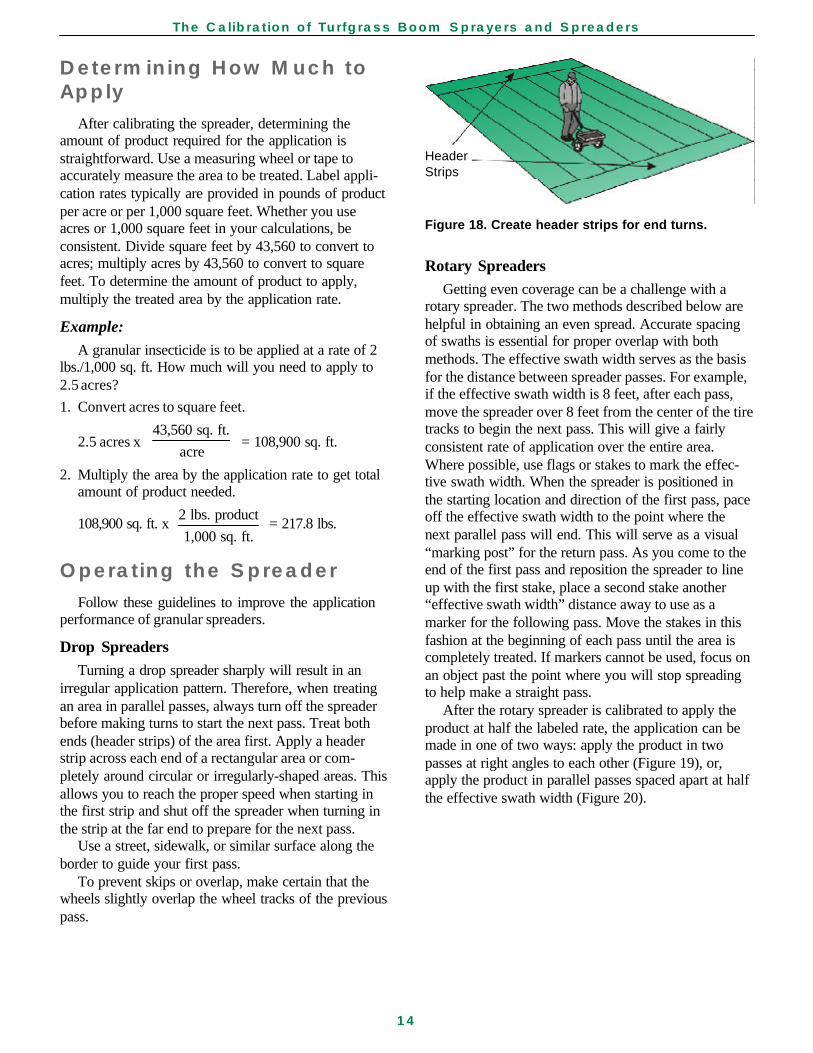
HeaderStrips
Figure 18. Create header strips for end turns.
Rotary SpreadersGetting even coverage can be a challenge with a
rotary spreader. The two methods described below arehelpful in obtaining an even spread. Accurate spacingof swaths is essential for proper overlap with bothmethods. The effective swath width serves as the basisfor the distance between spreader passes. For example,if the effective swath width is 8 feet, after each pass,move the spreader over 8 feet from the center of the tiretracks to begin the next pass. This will give a fairlyconsistent rate of application over the entire area.Where possible, use flags or stakes to mark the effec-tive swath width. When the spreader is positioned inthe starting location and direction of the first pass, paceoff the effective swath width to the point where thenext parallel pass will end. This will serve as a visual“marking post” for the return pass. As you come to theend of the first pass and reposition the spreader to lineup with the first stake, place a second stake another“effective swath width” distance away to use as amarker for the following pass. Move the stakes in thisfashion at the beginning of each pass until the area iscompletely treated. If markers cannot be used, focus onan object past the point where you will stop spreadingto help make a straight pass.
After the rotary spreader is calibrated to apply theproduct at half the labeled rate, the application can bemade in one of two ways: apply the product in twopasses at right angles to each other (Figure 19), or,apply the product in parallel passes spaced apart at halfthe effective swath width (Figure 20).
The Calibration of Turfgrass Boom Sprayers and Spreaders
15
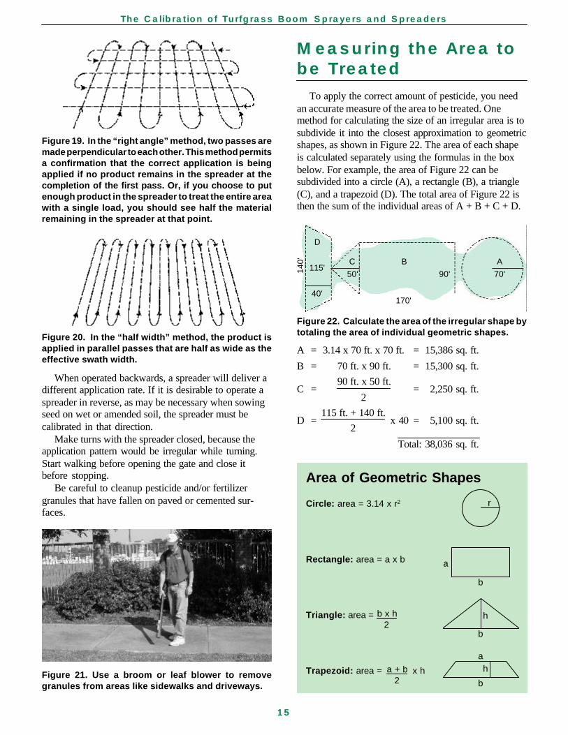
Figure 20. In the “half width” method, the product isapplied in parallel passes that are half as wide as theeffective swath width.
When operated backwards, a spreader will deliver adifferent application rate. If it is desirable to operate aspreader in reverse, as may be necessary when sowingseed on wet or amended soil, the spreader must becalibrated in that direction.
Make turns with the spreader closed, because theapplication pattern would be irregular while turning.Start walking before opening the gate and close itbefore stopping.
Be careful to cleanup pesticide and/or fertilizergranules that have fallen on paved or cemented sur-faces.
Area of Geometric Shapes
Circle: area = 3.14 x r2
Rectangle: area = a x b
Triangle: area =
Trapezoid: area = x h
b x h2
a + b2
D
C B A115'
50' 90' 70'
40'170'
Figure 22. Calculate the area of the irregular shape bytotaling the area of individual geometric shapes.
A = 3.14 x 70 ft. x 70 ft. = 15,386 sq. ft.
B = 70 ft. x 90 ft. = 15,300 sq. ft.
90 ft. x 50 ft.
2
115 ft. + 140 ft.
2
Total: 38,036 sq. ft.
C = = 2,250 sq. ft.
D = x 40 = 5,100 sq. ft.
r
a
b
h
b
ah
b
Measuring the Area tobe Treated
To apply the correct amount of pesticide, you needan accurate measure of the area to be treated. Onemethod for calculating the size of an irregular area is tosubdivide it into the closest approximation to geometricshapes, as shown in Figure 22. The area of each shapeis calculated separately using the formulas in the boxbelow. For example, the area of Figure 22 can besubdivided into a circle (A), a rectangle (B), a triangle(C), and a trapezoid (D). The total area of Figure 22 isthen the sum of the individual areas of A + B + C + D.
140'
Figure 21. Use a broom or leaf blower to removegranules from areas like sidewalks and driveways.
Figure 19. In the “right angle” method, two passes aremade perpendicular to each other. This method permitsa confirmation that the correct application is beingapplied if no product remains in the spreader at thecompletion of the first pass. Or, if you choose to putenough product in the spreader to treat the entire areawith a single load, you should see half the materialremaining in the spreader at that point.
References
• Boerboom, C., C. Ramsay, G. Thomasson, G.Stahnke, and R. Maleike. 1996. Turf andOrnamental Weed Management Principles.Washington State University.
• Guide for Preparing Field Sprayer CalibrationProcedures. 2001. Technical Standards of theAmerican Society of Agricultural Engineers. ASAEEP367.2 Jan01.
• Martin, A., T. Gibb, Z. Reicher, and C. Throssell.2000. “Turf Pest Control, Category 3b.” PesticideApplicator Training Manual. Purdue University.
• Merrigan, S. D. and P.B. Baker. 1992. PesticideApplicator Training Manual: Category 3 Turf andOrnamentals, Tucson: University of Arizona.
• Nixon, P., T. Voigt, S. Penix, and R. Wolf. 1996.Illinois Pesticide Applicator Training ManualTurfgrass, Special Publication 39-1. Urbana:University of Illinois.
• Ozkan, H. E. 1991. Calibrating Turfgrass ChemicalApplication Equipment. Extension Bulletin 817. TheOhio State University.
• Procedure for Calibrating Granular Applicators.2001. Technical Standards of the American Societyof Agricultural Engineers. ASAE EP371.1 Jan01.
• Roberson, G. 1999. Calibrating Field Sprayers, AG-587. North Carolina Cooperative Extension Service.
• Sicheneder, K. 1998. “Turfgrass Pest Management.”A Training Manual for Commercial PesticideApplicators. Michigan State University ExtensionBulletin E-2327.
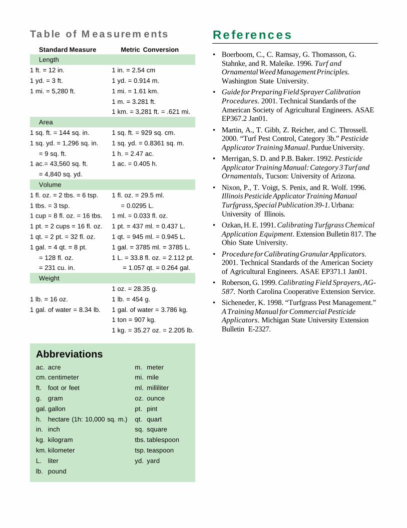
Table of MeasurementsStandard Measure Metric Conversion
Length
1 ft. = 12 in. 1 in. = 2.54 cm
1 yd. = 3 ft. 1 yd. = 0.914 m.
1 mi. = 5,280 ft. 1 mi. = 1.61 km.
1 m. = 3.281 ft.
1 km. = 3,281 ft. = .621 mi.
Area
1 sq. ft. = 144 sq. in. 1 sq. ft. = 929 sq. cm.
1 sq. yd. = 1,296 sq. in. 1 sq. yd. = 0.8361 sq. m.
= 9 sq. ft. 1 h. = 2.47 ac.
1 ac.= 43,560 sq. ft. 1 ac. = 0.405 h.
= 4,840 sq. yd.
Volume
1 fl. oz. = 2 tbs. = 6 tsp. 1 fl. oz. = 29.5 ml.
1 tbs. = 3 tsp. = 0.0295 L.
1 cup = 8 fl. oz. = 16 tbs. 1 ml. = 0.033 fl. oz.
1 pt. = 2 cups = 16 fl. oz. 1 pt. = 437 ml. = 0.437 L.
1 qt. = 2 pt. = 32 fl. oz. 1 qt. = 945 ml. = 0.945 L.
1 gal. = 4 qt. = 8 pt. 1 gal. = 3785 ml. = 3785 L.
= 128 fl. oz. 1 L. = 33.8 fl. oz. = 2.112 pt.
= 231 cu. in. = 1.057 qt. = 0.264 gal.
Weight
1 oz. = 28.35 g.
1 lb. = 16 oz. 1 lb. = 454 g.
1 gal. of water = 8.34 lb. 1 gal. of water = 3.786 kg.
1 ton = 907 kg.
1 kg. = 35.27 oz. = 2.205 lb.
Abbreviationsac. acre m. meter
cm. centimeter mi. mile
ft. foot or feet ml. milliliter
g. gram oz. ounce
gal. gallon pt. pint
h. hectare (1h: 10,000 sq. m.) qt. quart
in. inch sq. square
kg. kilogram tbs. tablespoon
km. kilometer tsp. teaspoon
L. liter yd. yard
lb. pound