Embed Size (px)
Citation preview

By ARC Advisory Group
ARC WHITE PAPER
NOVEMBER 2009
The Business Value Proposition of Control in the Field
Executive Overview .................................................................... 3
Control in the Field Provides Enhanced Process Integrity .................. 5
Testing Control in the Field Performance with High Fidelity Simulation 8
Performance Benefits Quantified .................................................. 13
Which Applications Can Benefit? .................................................. 16
Conclusions & Recommendations ................................................. 19
THOUGHT LEADERS FOR MANUFACTURING, ENERGY, & SUPPLY CHAIN

ARC White Paper • November 2009
2 • Copyright © ARC Advisory Group • ARCweb.com
Process Integrity:•Field Control Enables Truly Distributed Control and Single Loop Integrity• Network Management and Link Active Scheduler Maintain high Network Availability•Fieldbus Safety System Concept Provides a Path to Higher Process Availability
Process Integrity:•Field Control Enables Truly Distributed Control and Single Loop Integrity• Network Management and Link Active Scheduler Maintain high Network Availability•Fieldbus Safety System Concept Provides a Path to Higher Process Availability
Control in the Field is a Key Part of the Process Integrity Provided by FOUNDATION Technology
Control in the Field Provides Superior Reaction to Deterministic Disturbance in the Process
ARC White Paper • November 2009
Copyright © ARC Advisory Group • ARCweb.com • 3
The real differentiator between FOUNDATION
Fieldbus and its counterparts in process
automation, such as Profibus PA and HART, is
the incorporation of a function block structure
and other supporting functions that really
make FOUNDATION technology a complete
infrastructure for process automation.
Executive Overview
The replacement of 4-20 mA technology with a digital network was a big factor in the development of FOUNDATION technology, but that is only part of the equation. The real differentiator between FOUNDATION Fieldbus and its counterparts in process automation, such as Profibus PA and HART, is the incorporation of a function block structure and other supporting func-tions that really make FOUNDATION technology a complete infrastructure for process automation. ARC outlined this philosophy in a previous white pa-per where FOUNDATION Fieldbus is described as a true automation
infrastructure to achieve operational excellence in process plants.
Embedded control functionality in field devices, otherwise known as field control, is one of the key enablers for achieving high availability con-trol and a stepping-stone toward single loop integrity. The premise is simple. With control at
the device level, control is truly distributed, and there is truly no single point of failure in the system above the H1 level. If there is a malfunction in the HMI and a loss of visibility into the process, controllers, or any other component in the system and the control loop, including intelligent field devices, actuators and positioners, and the network, remain unaffected. In cases where control resides in the DCS, field level control can add another level of redundancy. Many end users have already managed to avoid un-planned downtime when field level control took over after a failure in the system.
Field level control means not only increased availability and reliability, but also increased flexibility. Controllers are free to handle higher-level control functions such as advanced control and optimization. FOUNDATION Field-bus allows for "dynamically instantiable function blocks", meaning that function blocks can be activated in different components of the system as they are required. There is also a large library of different block types that can be used aside from basic PID, such as switches, alarms, and so on.
The adoption of FOUNDATION Fieldbus has skyrocketed over the past sev-eral years. ARC estimates that the total market for fieldbus products and services is rapidly approaching a billion dollars. Those actually implement-ing the control in the field functionality, however, are well in the minority.
ARC White Paper • November 2009
4 • Copyright © ARC Advisory Group • ARCweb.com
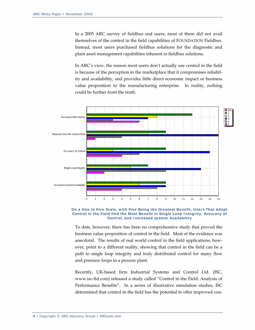
In a 2005 ARC survey of fieldbus end users, most of them did not avail themselves of the control in the field capabilities of FOUNDATION Fieldbus. Instead, most users purchased fieldbus solutions for the diagnostic and plant asset management capabilities inherent in fieldbus solutions.
In ARC’s view, the reason most users don’t actually use control in the field is because of the perception in the marketplace that it compromises reliabil-ity and availability, and provides little direct economic impact or business value proposition to the manufacturing enterprise. In reality, nothing could be further from the truth.
To date, however, there has been no comprehensive study that proved the business value proposition of control in the field. Most of the evidence was anecdotal. The results of real world control in the field applications, how-ever, point to a different reality, showing that control in the field can be a path to single loop integrity and truly distributed control for many flow and pressure loops in a process plant.
Recently, UK-based firm Industrial Systems and Control Ltd. (ISC, www.isc-ltd.com) released a study called “Control in the Field: Analysis of Performance Benefits”. In a series of illustrative simulation studies, ISC determined that control in the field has the potential to offer improved con-
On a One to Five Scale, with Five Being the Greatest Benefit, Users That Adopt Control in the Field find the Most Benefit in Single Loop Integrity, Accuracy of
Control, and Increased system Availability
N/A12345
1514131211109876543210
Increased System Availability
Single Loop Integrity
Accuracy of Control
Reduced Cost Per Control Point
Increased Plant Safety

ARC White Paper • November 2009
Copyright © ARC Advisory Group • ARCweb.com • 5
trol loop performance due to its ability to offer faster sample rates and shorter latencies in the read-execute-write cycle of a control loop. ISC ex-amined the differences in timing and sequencing associated with control in the field versus a scheme employing control in the DCS to establish typical latencies and sample rates that limit control performance. Many different scenarios and process dynamics were tested, and the results and corres-ponding benefits are outlined in this report. Whilst benefits of increased integrity, flexibility, and reliability can be attributed to all control in the field loops, ISC found that control loop performance benefits can be quite significant in fast process loops.
Control in the Field Provides Enhanced Process Integrity
In ARC’s analysis of FOUNDATION Fieldbus as an automation infrastruc-ture, we found that FOUNDATION Fieldbus provides business value in three key areas -- process integrity, business intelligence, and open and scalable integration of information across process manufacturing plants. Control in
the field is a key element in providing significantly enhanced process integrity for many applications and control loops.
Link Active Scheduler Provides Communications Reliability
Communications on the fieldbus seg-ment, including highly deterministic scheduled data and low priority un-scheduled data, are managed by the
Link Active Scheduler (LAS). The FOUNDATION Link Active Scheduler is an arbitrator that decides which devices will have access to the
fieldbus network and when. In fieldbus, LASs preside over only their par-ticular local bus segment. With an appropriate configuration of devices
FB
FB
HMI
Controller
ControlNetwork
FBFB
FBFBFB
HMI
Controller
ControlNetwork
Field Control Keeps the Process Running, Despite Loss of Visualization, Control Network,
and Controller Functions
ARC White Paper • November 2009
6 • Copyright © ARC Advisory Group • ARCweb.com
One class of control loops where the greater
performance benefits of CIF could be
considerable is where controllers are
responding to one-off spurious events to
maintain operations and avoid the activation
of the safety system.
and data transfer on a segment, the LAS works in a highly available and deterministic fashion.
The implementation of a backup Link Active Scheduler (BLAS) is a crucial step in providing high availability fieldbus control. Most suppliers current-ly support Link Active Scheduling (LAS) technology, but not all provide full BLAS support for all devices on the bus that have this function. The advantage of having a BLAS is that it will take over in the event of failure of the primary LAS. Any device can function as an LAS, and in some supplier control schemes, any device, or all devices, on the bus can also function as a BLAS, ensuring that network traffic will resume uninterrupted in the event of a failure.
Many Paths to Redundancy
There are ways in which redundancy, recon-figuration and fail-safe strategies can be built-in to respond to certain failures in the system. Since function block can be executed in differ-ent devices, CIF can be configured to take advantage of parallel computations or to mi-nimize data traffic depending on a given application need.
With Spurious Events, Control in the Field Keeps Things Running
One class of control loops where the greater performance benefits of CIF could be considerable is where controllers are responding to one-off spu-rious events to maintain operations and avoid the activation of the safety system. A good example of this is the pressure control of fuel gas supply for a pair of gas turbines in a power generating plant. When the gas tur-bines are operating normally the pressure control is not too demanding. However, if one of the gas turbines trips, the fuel gas supply pressure will rise very quickly and the controller has to respond rapidly in order to re-duce the pressure and prevent the remaining gas turbine from tripping on a high fuel gas pressure limit. The improved speed of response provided by CIF may offer substantial benefits in such control loops.

ARC White Paper • November 2009
Copyright © ARC Advisory Group • ARCweb.com • 7
Improved Reliability and Availability
There is evidence to support that control in the field has an 80 percent in-crease in meantime between failures compared to traditional DCS control. The increased MTBF combined with the reduction in data transfers re-quired substantially increases reliability and availability. The overall reduction in network traffic also increases network availability, in spite of the trade off in the increased amount of device condition, status, and other data that must be passed to the DCS. There is also much more flexibility with control in the field. Once deployed, the function block execution can be transferred from one device or actuator to another.
Improved Security and Integrity
The reduced hardware requirement for control in the field provides fewer points of failure. The reduced number of connections between devices also similarly increases reliability. DCS and PLC hardware can also be freed of much of the load of performing control tasks and can be devoted to other processes that are increasingly finding their way into today’s controllers, such as advanced control and optimization, simulation, asset management related tasks, historical data collection, and so on.
Communication Classes Promote Reliability
There are several different types of communication classes associated with FOUNDATION Fieldbus. Primary distinctions are made between sche-duled and unscheduled transfers of data. Scheduled transfers are completely deterministic, while unscheduled data transfers, such as those associated with device health, status, and alarms, are a separate class. Un-scheduled data transfers happen only when there is enough available bandwidth after the scheduled transfers occur. It is good practice to ensure that your networks are not overburdened with scheduled transfers to en-sure some level of determinism for unscheduled transfers, but this is not likely to be a great issue in most applications. It is good practice not to use more than 50 percent of the scheduled scan time (the macrocycle) for sche-duled transfers. Many suppliers recommend considering periodically requested unscheduled communications along with scheduled communica-tions. The sum should not exceed 70 percent of the macrocycle.
With FOUNDATION Fieldbus, duration of data transfers and execution of function blocks are strictly defined. Macrocycle should be determined by the requirements from the nature of the process under control. Macrocycle

ARC White Paper • November 2009
8 • Copyright © ARC Advisory Group • ARCweb.com
length is also determined by number of devices on a segment and the trans-fers and computations taking place. The macrocycle can be engineered to fit the application by adjusting the number of devices and data transfers on a segment. These are considerations that must be undertaken by the de-signer of the system.
FOUNDATION Fieldbus also has sophisticated mechanisms to handle recon-figuration, instantiation, sub-scheduling, synchronization, and data transfer optimization. Some fieldbus devices may only support a few different data transmission links at any one time. This can limit the functionality achieved by control in the field. It is important to be rigorous in determin-ing the macrocycle length to ensure the system functions properly. Using the right design tools is a must.
Testing Control in the Field Performance with High Fidelity Simulation
In real world conditions, process control loops include constraints such as slew rate and saturation limits of the actuator, the mixture of continuous and discrete control time dynamics present, and other factors. Obviously, using a real plant to test the performance of control in the field versus DCS based control was not possible, because conditions cannot be controlled and real plants have to continue operating to make money. For these rea-sons, ISC used a high-fidelity simulation with the pertinent features of the process, sensor, actuator and controller. The simulations developed by ISC were designed to duplicate the same conditions found in different processes and controller tuning for several different scenarios for both con-trol in the field and the DCS. Simulations provided measures of process improvements, reduced process variability, and reaction to unplanned events.
Simulations used by ISC to evaluate the controller performance included a discrete-time PI controller and delay, with three different combinations of sample rate and delay to reflect the three controller options being eva-luated. A range of different process dynamics were used, from an ideal liquid flow loop to progressively slower processes with longer deadtimes. ISC also introduced a deterministic disturbance to the process derived from
ARC White Paper • November 2009
Copyright © ARC Advisory Group • ARCweb.com • 9
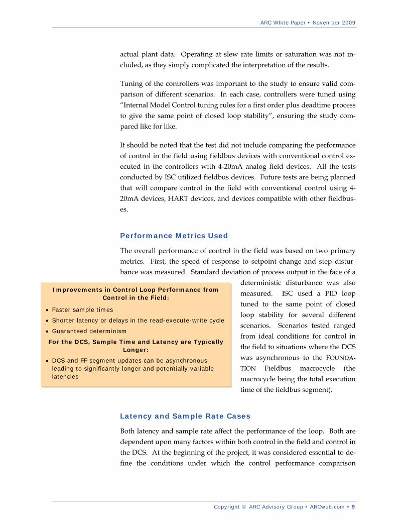
Improvements in Control Loop Performance from Control in the Field:
• Faster sample times
• Shorter latency or delays in the read-execute-write cycle
• Guaranteed determinism
For the DCS, Sample Time and Latency are Typically Longer:
• DCS and FF segment updates can be asynchronous leading to significantly longer and potentially variable latencies
actual plant data. Operating at slew rate limits or saturation was not in-cluded, as they simply complicated the interpretation of the results.
Tuning of the controllers was important to the study to ensure valid com-parison of different scenarios. In each case, controllers were tuned using “Internal Model Control tuning rules for a first order plus deadtime process to give the same point of closed loop stability”, ensuring the study com-pared like for like.
It should be noted that the test did not include comparing the performance of control in the field using fieldbus devices with conventional control ex-ecuted in the controllers with 4-20mA analog field devices. All the tests conducted by ISC utilized fieldbus devices. Future tests are being planned that will compare control in the field with conventional control using 4-20mA devices, HART devices, and devices compatible with other fieldbus-es.
Performance Metrics Used
The overall performance of control in the field was based on two primary metrics. First, the speed of response to setpoint change and step distur-bance was measured. Standard deviation of process output in the face of a
deterministic disturbance was also measured. ISC used a PID loop tuned to the same point of closed loop stability for several different scenarios. Scenarios tested ranged from ideal conditions for control in the field to situations where the DCS was asynchronous to the FOUNDA-
TION Fieldbus macrocycle (the macrocycle being the total execution time of the fieldbus segment).
Latency and Sample Rate Cases
Both latency and sample rate affect the performance of the loop. Both are dependent upon many factors within both control in the field and control in the DCS. At the beginning of the project, it was considered essential to de-fine the conditions under which the control performance comparison
ARC White Paper • November 2009
10 • Copyright © ARC Advisory Group • ARCweb.com
Three Cases Considered:
• Case 1: Ideal Control in the Field
• Case 2: Fast Control in the DCS (Synchronous with the FF Macrocycle)
• Case 3: Fast Control in the DCS (Asynchronous with the FF Macrocycle)
Details of the Simulation:
• Simple continuous process model couples to discrete PI controller
• Controllers tuned to same stability to allow comparison
• Speed of response to setpoint change and disturbance rejection assessed
• Repeated for different process dynamics
should be made and how this may vary with different situations likely to be encountered in different applications.
Ideal Control in the Field
Ideal single loop control in the field was assumed to have the fastest latency (105msec) and fastest typical macrocycle (150msec) for the sample rate. In practice, FF devices may have slower execution time or involve the execu-tion of more functions. Blocks may also be configured to execute in different locations. All of these can increase both the latency and sample rate. When there are multiple loops on the same FF segment, the latency stays the same, but the sample rate increases.
DCS Running Control with Fieldbus Devices
ISC tested different scenarios for control with a fieldbus system to compare performance of control in the field with conventional control in the DCS or PLC. The first of these was conventional DCS/PLC control with fieldbus devices. In this scenario, three scheduled data transfers are considered. The first is from the sensor to the controller for the process value. In this scenario, controller output must then be sent from the controller to the ac-tuator. Finally, the actuator must communicate back to the function for the back calculation. Although the DCS is able to execute the PID function block faster, at a speed of 20 milliseconds at a maximum, the added over-
head for data transfer requirements es-sentially negated this performance benefit. The fact that update rates for DCS controller blocks are often set at 0.5 or one second further limits the attaina-ble performance.
In these conventional control scenarios, the latency or delay between reading the sensor data and writing the control signal to the actuator can be as short as 125msec. The sample rate, however, might be no faster than 500msec even for a fast loop. Slow sample rate can be
a major limitation on controller performance in such situations. It is rare in practice to find scan times below 500msec, even though some DCS may be capable of faster scan times. Without any constraint imposed by the DCS
ARC White Paper • November 2009
Copyright © ARC Advisory Group • ARCweb.com • 11
on the scan time, the fastest update rate possible would still be 180msec be-cause of the maximum of 50 percent of the macrocycle dedicated to scheduled data transfers. In this case, latencies of 125msec and sample times of 500msec were used, representing the fastest typical loop that might be practically used.
With multiple controllers operating on the same FF segment, the timing of control loop operation becomes increasingly complex. Even with a few control loops in a single FF segment, the fastest possible update rate quickly exceeds the 500msec update rate considered here and 1-second scan times may be more typical of what can be achieved.
Fast Control in the DCS, Asynchronous with the FF Macrocycle
A bigger source of controller degradation in the DCS is the potential for asynchronous updates from field devices and output of data from PID block execution. This has the potential to increase the latency of the scan time. You can minimize the chance of this occurring by having DCS scan time set to half the FF segment macrocycle length, or using a DCS that has specific functionality to maintain synchronization.
The third case examined is fast single loop control in the DCS that was asynchronous with the FF macrocycle. This is essentially identical to the second case, but where the DCS and FF segment are considered to be asyn-chronous, resulting in a latency of 625msec and a sample rate of 500msec. Situations where the DCS and FF segment change from being synchronous to asynchronous during operation were not considered.
Although there are ways to mitigate against this as mentioned previously, this situation does arise and degrade control loop performance. These three cases have been selected to represent typical, but fast, possible timings within a practical control loop. In practice, latencies and sample rates will be different, and there may be situations where control in the field may have comparable latencies and sample rates to control in the DCS, especial-ly situations where there are few data transfers but many calculations.
Should Control Reside in the Actuator or Device?
Control in the field can be executed in the device or the actuator. The topic of which it should reside in has been a traditional topic of debate. When
ARC White Paper • November 2009
12 • Copyright © ARC Advisory Group • ARCweb.com
control in the field resides in the sensor, there are essentially two scheduled data transfers. When control executes in the actuator, only one scheduled transfer is required from the sensor to the actuator. If control executes in the H1 fieldbus interface card or module, as it is in many cases today, there are still the same three data transfers that are required in a conventional DCS control scheme. For this reason, it often makes the most sense for con-trol to reside in the actuator. There is also the added benefit of integrity even in the case of a lost sensor.
With control execut-ing in the actuator, a flow control loop could ideally be up-dated as fast as every 105msec with the control executed in the actuator. This is not the absolute fast-est latency possible, as certain combina-tions of devices could do it faster. Instead,
the 105msec represents something that is attainable using typically fast de-vices. While there are very fast fieldbus devices available from automation suppliers today, many of the older fieldbus devices are much slower, so it is a good idea to check execution times for all the devices you are using to measure their impact on performance.
Process Scenarios: from Very Fast to Very Slow
In the simulations conducted by ISC, the first process considered was a “very fast” liquid flow process, followed by a “fast “ process and a “me-dium” speed process. The three cases were then all tuned to give a ten percent overshoot. The “very fast process” case used by ISC represented an ideal liquid flow process, with some dynamics associated with a fast valve and sensor. The dynamics included a deadtime of 0.25 seconds and a time constant of 0.5 seconds. This can be viewed as the fastest process dynamics likely found in process plants.
The second process case used in the study was a “fast process” with mod-erately fast dynamics. This “fast process” represents a typical flow or
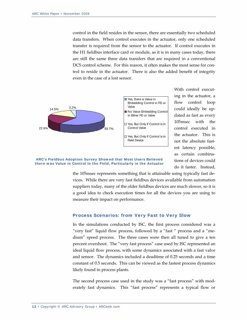
59.7%22.6%
14.5% 3.2%
Yes, there is Value inEmbedding Control in FD orValveNo Value Embedding Controlin Either FD or Valve
Yes, But Only if Control is inControl Valve
Yes, But Only if Control is inField Device
ARC’s Fieldbus Adoption Survey Showed that Most Users Believed there was Value in Control in the Field, Particularly in the Actuator

ARC White Paper • November 2009
Copyright © ARC Advisory Group • ARCweb.com • 13
pressure process with dynamics associated with a valve and sensor. The dynamics in the “fast process” had a deadtime of 0.25 seconds and a time constant of 2 seconds. The deterministic disturbance was re-scaled tempo-rarily to keep the frequency content of the disturbance signal relative to process dynamics similar (this was done to allow comparison across the different process types).
The “medium” speed process tested in the simulation featured a deadtime of 1 second and a time constant of 5 seconds. The deterministic disturbance was also re-scaled to be appropriate for the dynamics of the process. A “slow” process was also tested, with deadtime of greater than five seconds.
Performance Benefits Quantified
Control in the field featured the best performance in both the step response and the disturbance rejection in the very fast, and medium speed processes. The faster response and improved attenuation of the disturbance provided by control in the field does require the actuators to be driven more aggres-sively. Consequently, such improvements are only possible if the actuator
can provide the extra speed and range defined by slew rate limits and sa-turation limits.
The inherent determinism of FOUNDATION Fieldbus communications can ac-tually eliminate some of the transmission of control related data to the DCS. This provides a corres-ponding reduction in control loop time delays, which means faster up-dates. Reducing delays in the loop also means that
you can control that much closer to the setpoint. The increased speed of response also means that applications with faster loops, such as fluidic flow processes, will experience the greatest performance benefits.
0 2 4 6 8 10 12 14 16 18 2048
50
52
54
56
58
60
62
Time (seconds)
Pro
cess
Out
put (
%)
SetpointCase 1 - CIFCase 2 - Control in DCS (sync)Case 3 - Control in DCS (async)
ARC White Paper • November 2009
14 • Copyright © ARC Advisory Group • ARCweb.com
Performance Benefits in Control Loop Timing and Sequencing
The communication features of FOUNDATION Fieldbus provide many bene-fits when it comes to control loop timing and sequencing. FOUNDATION Fieldbus is highly deterministic. The data rate of H1 fieldbus communica-tions is frequently a target for criticism, since it operates at a speed of 31.25kbps, but the protocol provides extremely fast update rates at up 125 milliseconds. Point to point communications between devices, actuators, and controllers is supported. Controllers, devices, and actuators all have point-to-point communications with each other and all have the capability to support control function block execution.
Greatest Benefit is Derived From Fast Processes
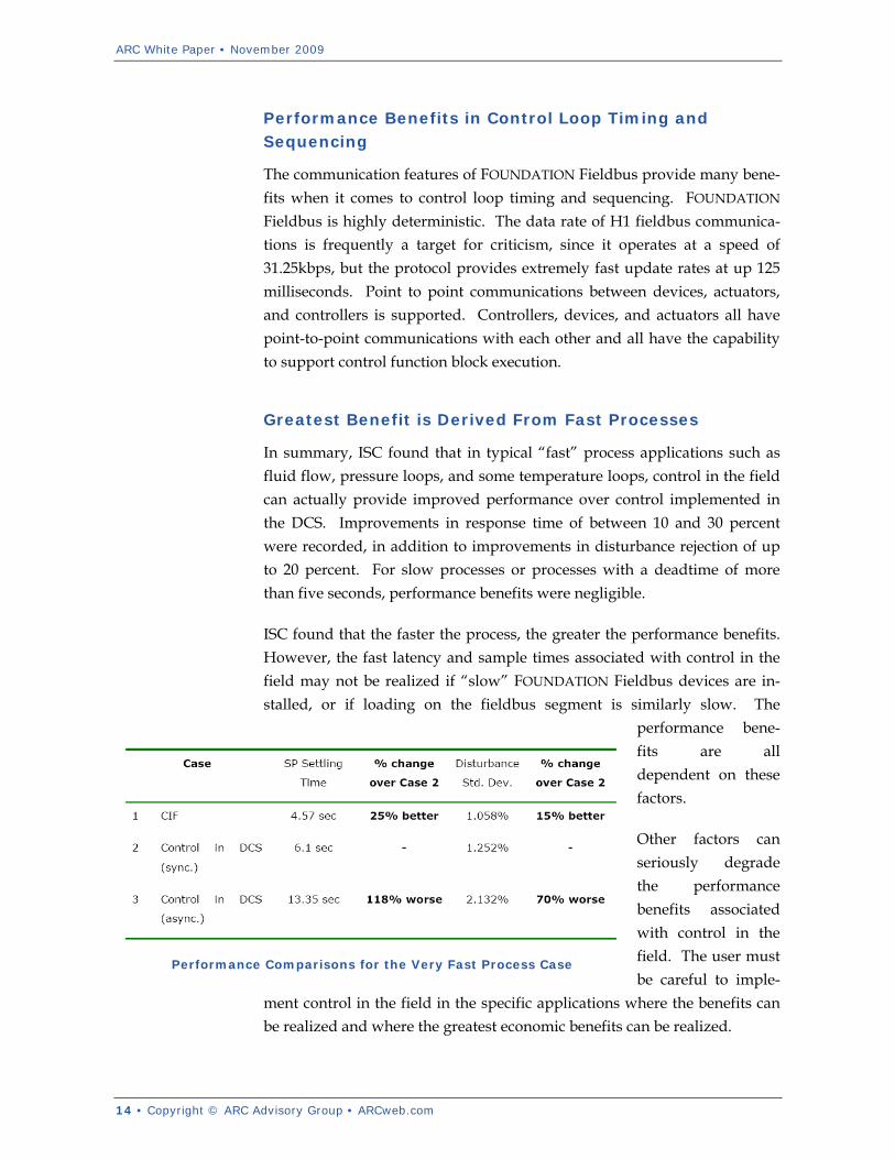
In summary, ISC found that in typical “fast” process applications such as fluid flow, pressure loops, and some temperature loops, control in the field can actually provide improved performance over control implemented in the DCS. Improvements in response time of between 10 and 30 percent were recorded, in addition to improvements in disturbance rejection of up to 20 percent. For slow processes or processes with a deadtime of more than five seconds, performance benefits were negligible.
ISC found that the faster the process, the greater the performance benefits. However, the fast latency and sample times associated with control in the field may not be realized if “slow” FOUNDATION Fieldbus devices are in-stalled, or if loading on the fieldbus segment is similarly slow. The
performance bene-fits are all dependent on these factors.
Other factors can seriously degrade the performance benefits associated with control in the field. The user must be careful to imple-
ment control in the field in the specific applications where the benefits can be realized and where the greatest economic benefits can be realized.
Performance Comparisons for the Very Fast Process Case
ARC White Paper • November 2009
Copyright © ARC Advisory Group • ARCweb.com • 15
Key Performance Benefits Provided by Control in the Field
• Improved Control Loop Performance
• Increased Reliability and Availability
• Improved Loop Integrity
• Reduced Loading on DCS/PLC and Network
• Lower Capital and Installation Costs
• Reduced Operating Costs
Reduced Installed and Operational Costs
Reduced capital and installation costs were some of the primary justifica-tions for early fieldbus installations. Unfortunately, many did not work out that way because of the learning curve required by many systems integra-tors and end users. That is no longer an issue today with hundreds of large fieldbus installations worldwide in a range of industries from refining to nuclear power generation.
The cost reduction opportunities of a true fieldbus installation that incorpo-rates control in the field where it is appropriate can significantly reduce installed and overall capital costs. Reduced wiring, footprint, and signifi-cantly reduced hardware requirements in the form of I/O and controllers. The additional wiring needed for powering devices and redundant control schemes also must be considered, but there is still room for significant re-ductions.
ARC has always advocated that the true cost savings with fieldbus, howev-er, is not associated with installed cost, but lifecycle cost. This rule is no different when you deploy control in the field. The increased reliability and availability of the process with control in the field significantly reduced un-planned incidents and provides greater accuracy of control.
Performance Improvements Depend on Implementation
Although there can be significant performance benefits to using control in the field, it is also true that PID execution times in fieldbus devices are typi-cally slower than PID executing in the DCS or the H1 card. It is really the reduction in overall data transfer that provides the performance improve-ment. For example, if you were to execute control in the H1 card the loop
latency would increase to 125msec, and PI execution might be 10msec shorter.
Overall performance improvement de-pends on the combination of devices you use, the location of the control execution, and the timing specifications. The wrong combination may provide no benefit at all. In the case of several control loops
with multiple read/write operations on the same FF segment, timings de-pend on the scheduled transfers by the LAS. Exact timing sequences are difficult to determine. The fastest macrocycle length becomes dominated

ARC White Paper • November 2009
16 • Copyright © ARC Advisory Group • ARCweb.com
by the constraint of scheduled data transfers accounting for less than 50 percent of the scan time.
Loop Characteristics Define Performance Improvements
Performance improvements of control in the field versus traditional DCS control also depend on many features of the loop. In addition to the three cases described here of the very fast, fast, and medium processes, ISC ex-amined cases with much slower process dynamics with a time constant of 10 seconds and a corresponding settling time of 40 seconds. For these very slow processes, the benefits of control in the field become minimal. Processes with significant deadtime greater than five seconds do not benefit much at all with control in the field versus DCS control.
The aggressive control action required to achieve faster control response for control in the field is also limited by the slew rate and saturation limits on the actuator and reduces and potential improvements for control in the field.
Latency and sample rate depend on the DCS scan time, synchronization between DCS and FOUNDATION Fielbus, as well as the macrocycle. If the latency of the control in the field increases from the assumed 105msec, the amount of performance benefit over control in the DCS is reduced. ISC recognized that there are cases where control in the DCS offers superior control performance, such as those where there are few data transfers and many function blocks that need to be executed. Improvements in the dis-turbance rejection also have similar features to the previously reported results on control performance improvements.
Which Applications Can Benefit?
As we stated before, the faster processes tend to benefit more from control in the field. Benefits of control in the field are also reduced in situations where processes are intentionally tuned for slow controller response or where the slew rate and saturation limits may constrain a faster response. There are also many specialized loops that require very fast sample rates but may require sensors and actuators that are non fieldbus-compliant, such as those that exist in rolling mills in the metals industry.

ARC White Paper • November 2009
Copyright © ARC Advisory Group • ARCweb.com • 17
In spite of these limitations, there will be many loops where performance benefits from CIF could be realized, including many flow and pressure loops and some fast temperature, pH, position and speed loops. Many lev-el and temperature loops will not benefit, but the improved flow and pressure control provided by control in the field ultimately mean that the performance of these slower loops could also be improved because of the complex interactions of control loops in process plants. However, the per-formance improvements of control in the field must ultimately be linked to a business value proposition, which is the measure of value for the imple-mentation of any new technology in the plant. Additional benefits above and beyond the control performance include reducing product variability, speed of grade changes, reduced time to startup, increased availability, and energy savings.
With that said, many applications can benefit greatly from control in the field. Many of these exist outside the realm of the traditional refining and petrochemical applications where so many of today’s FOUNDATION Field-bus installations exist.
Pulp and Paper Applications
In the wet end of the paper manufacturing process, for example, there are several important flow loops that are subject to various disturbances, such as those involved when undergoing a grade change. These loops in the wet end of the process have a big impact on minimizing disturbances of the main control loops on the paper machine itself, such as those used to con-trol moisture and base weight. These paper machine loops have long deadtimes and thus have a limited ability to respond. Using control in the field in the wet end of the process can reduce process variability in the dry end.
Power Generation and Combustion Control Applications
Power generation has long been one of the major users of FOUNDATION Fieldbus, even in nuclear applications. There are many important pressure and flow loops in a typical power generation facility that have an impact on overall plant performance, and can determine how fast a power generation facility can handle load changes or increase process efficiency.
Some control algorithms used in power generation are highly complex and adapted to cope with a wide range of processes. Many of these loops in

ARC White Paper • November 2009
18 • Copyright © ARC Advisory Group • ARCweb.com
existing plants are hard wired for 4-20mA. Even in these cases, however, control in the field could offer performance benefits for certain steam tem-perature and steam/feedwater pressure loops.
As we mentioned earlier, another good example of control in the field for power generation applications can be found in the loops that are used to control fuel gas supply for a pair of gas turbines. If one of the gas turbines happens to trip, fuel gas pressure rises quickly and the controller must re-spond in kind to avoid tripping the other turbine. Control in the field can offer the fast response required to keep this from happening.
In combustion control applications, the control of firing boilers can also benefit from the increased speed of response. Although there is a range of proprietary hardware designed to control these applications, control in the field may offer performance benefits without the hassles and complexities normally associated with maintaining such fit for purpose hardware.
Compressor Control Applications
Operating compressors close to the surge line can provide many economic benefits, as well as improved reliability and safety. The margin of safety applied is directly related to the magnitude and speed of disturbances the anti-surge pressure controller experiences and the speed at which it can re-spond. If the measurement is not updated and acted on faster than the compressor surges, then surges may occur between samples, in which case they may persist for several cycles before even being detected. High per-formance compressor applications usually use dedicated, fast control hardware to realize the required control performance. CIF will find limited benefit over such installations.
Similar to the case in turbine control systems, control in the field with stan-dard hardware has the potential to match the performance of dedicated compressor controls. One study showed that control in the field for com-pressor anti-surge control showed that control in the field for compressors could have a macrocycle time 325-460msec. Control calculations are done using control in the field and the more complex calculations are done in the DCS.

ARC White Paper • November 2009
Copyright © ARC Advisory Group • ARCweb.com • 19
Conclusions & Recommendations
The studies presented in this report have shown that control in the field has the potential to offer improved control loop performance over control in the DCS due to the faster sample rates and shorter latencies (delays) in the read-execute-write cycle of a control loop. ISC’s analysis has determined that control in the field is actually able to provide performance benefits for most regulatory control loops for pressure and flow applications. Achiev-ing the benefits of control in the field takes some thoughtful application and sufficient planning in the early stages of a project.
Most users today currently do not consider application of control in the field because of the perception that it somehow introduces increased risk or reduced availability. Embedded control functionality in field devices is one of the key enablers for achieving high availability control and a stepping-stone toward single loop integrity. Many users have already managed to avoid unplanned downtime when field level control took over after inter-face card failures and other failures in the process, such as loss of HMI.

ARC White Paper • November 2009
20 • Copyright © ARC Advisory Group • ARCweb.com
Analyst: Larry O'Brien
Editor: Dick Hill
Acronym Reference: For a complete list of industry acronyms, refer to our web page at www.arcweb.com/Research/IndustryTerms/
API Application Program Interface
B2B Business-to-Business
BPM Business Process Management
CAGR Compound Annual Growth Rate
CAS Collaborative Automation System
CMM Collaborative Manufacturing
Management
CPG Consumer Packaged Goods
CPM Collaborative Production
Management
CRM Customer Relationship
Management
DCS Distributed Control System
DOM Design, Operate, Maintain
EAM Enterprise Asset Management
ERP Enterprise Resource Planning HMI Human Machine Interface
IOp Interoperability
IT Information Technology
MIS Management Information System
OpX Operational Excellence
OEE Operational Equipment
Effectiveness
OLE Object Linking & Embedding
OPC OLE for Process Control
PAS Process Automation System
PLC Programmable Logic Controller
PLM Product Lifecycle Management
RFID Radio Frequency Identification
ROA Return on Assets
RPM Real-time Performance
Management
SCM Supply Chain Management
WMS Warehouse Management System
Founded in 1986, ARC Advisory Group has grown to become the Thought Leader in Manufacturing and Supply Chain solutions. For even your most complex business issues, our analysts have the expert industry knowledge and firsthand experience to help you find the best answer. We focus on simple, yet critical goals: improving your return on assets, operational performance, total cost of ownership, project time-to-benefit, and shareholder value.
All information in this report is proprietary to and copyrighted by ARC. No part of it may be reproduced without prior permission from ARC. This research has been sponsored in part by the Fieldbus Foundation. However, the opinions expressed by ARC in this paper are based on ARC's independent analysis.
You can take advantage of ARC's extensive ongoing research plus experience of our staff members through our Advisory Services. ARC’s Advisory Services are specifically designed for executives responsible for developing strategies and directions for their organizations. For membership information, please call, fax, or write to:
ARC Advisory Group, Three Allied Drive, Dedham, MA 02026 USA Tel: 781-471-1000, Fax: 781-471-1100, Email: [email protected]
Visit our web pages at www.arcweb.com

3 ALLIED DRIVE DEDHAM, MA 02026 USA 781-471-1000
USA | GERMANY | JAPAN | INDIA | CHINA | BRAZIL | ARGENTINA