Embed Size (px)
Citation preview
The Brazilian Pipeline Community II
Supplement to
Brazil oil & gas
Norway oil & gas
Saudi Arabia oil & gas
EPRASHEEDsignature seriesBrazil oil & gas
Norway oil & gas
Saudi Arabia oil & gas
INTRODUCTIONBrazil: An Innovator in the Global Pipeline Community
TRaNsPeTRO´s gas PIPelINe NeTwORkBy Marcelo Renno, Natural Gas Director of Transpetro
FRee sTaNDINg HYBRID RIseR FOR 1800 M waTeR DePTH By Francisco E. Roveri, Petrobras Research & Development Center - CENPES and Paulo Ricardo F. Pessoa, Petrobras Subsea Engineering Services - E&P - SERV and Francisco Henrique, Petrobras
IMPROvINg PIPelINe PeRFORMaNCeThe PRODUT program helps Petrobras improve operational reliability, increase capacity, and maintain environmental safety.By Ney Passos, Petrobras Brasil S.A., Rio de Janeiro, Brazil
CTDUT - a PaRTNeR IN R&D PROjeCTsBy Stella Faria Nunes - CTDUT, Project Manager and Raimar Van den Bylaardt, President CTDUT
CTDUT – a sHaReD sOlUTION FOR THe DevelOPMeNT OF PIPelINe TeCHNOlOgYBy Arthur J. F. Braga – CTDUT, Executive Manager and Sergio Damasceno Soares – PETROBRAS/CENPES, Engineer, MSC
sUPPORTINg aCaDeMIC DevelOPMeNTWith its Award for Pipeline Technology, Petrobras rewards new talent, and develops institutional marketing.By Wajid Rasheed
sOCIal ageNDa - sHaReD ResPONsIBIlITY BRINgs BeNeFITsPetrobras has a long and healthy tradition of social responsibility that stretches back to the company’s birth in the 1950s.By Wajid Rasheed
Contents4
EPRASHEEDsignature seriesBrazil oil & gas
Norway oil & gas
Saudi Arabia oil & gas
The Brazilian Institute of Petroleum and Gas (IBP) with the support of its Pipe-line Commission has been working to develop Brazil’s pipeline industry by helping companies in this sector oper-ate in a profitable, efficient, ethical and socially responsible way.
In this context, the Commission pro-motes the exchange of ideas and ex-perience amongst professionals in this industry and is active in the areas of norms standardization, promoting in-ternational trade missions and in the organization of courses and events.
Among the latter we can highlight the Rio Pipeline Conference and Exhibi-tion as a world class forum to debate the major issues facing the international pipeline industry.
Brazil oil & gas
Norway oil & gas
Saudi Arabia oil & gas
Brazil has the potential to export world class technology and services. For this to happen, an export culture needs to be cultivated. Part of this culture is a single source of technical material that focuses on Brazil while including the wider international observers. This supplement ‘The Brazilian Pipeline Community’ is a channel for companies, both oil and service to share expertise with the wider export market.
editorsMarcelo Renno, Francisco E. Roveri, Francisco Henrique, Andre Raposo, Paulo Ricardo F. Pessoa, Ney Passos, Stella Faria Nunes, Raimar Van den Bylaardt, Arthur J. F. Braga and Sergio Damasceno Soares
PublisherWajid [email protected]
Managing editorMajid [email protected]
João Carlos de LucaPresident, IBP
Wajid RasheedCEO & Founder, EPRasheed
58
18
23
28
31
32
The Brazilian Pipeline Community II
4 The Brazilian Pipeline Community
Innovations also extend to programs that work with and give back to the community. In fact, Petrobras has for decades recognized the need for environmental and social responsibility. Since its origins in the 1950s, the company has worked to foster interaction and participation of local communities. It has provided forums which allow affected communities to present their ideas regarding responsible hydrocarbon production and transportation.
And, with its Award for Pipeline Technology, Petrobras supports academic achievement in a way that rewards new talent and provides institutional marketing, while helping to create a new generation of innovative minds that will benefit society as a whole.
INTRODUCTION
Brazil: an Innovator in the global Pipeline Community
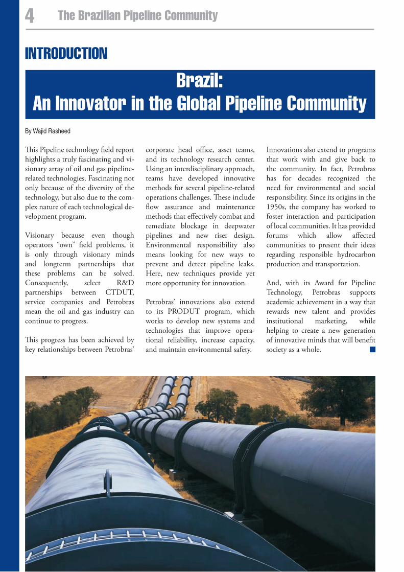
This Pipeline technology field report highlights a truly fascinating and vi-sionary array of oil and gas pipeline-related technologies. Fascinating not only because of the diversity of the technology, but also due to the com-plex nature of each technological de-velopment program.
Visionary because even though operators “own” field problems, it is only through visionary minds and longterm partnerships that these problems can be solved. Consequently, select R&D partnerships between CTDUT, service companies and Petrobras mean the oil and gas industry can continue to progress.
This progress has been achieved by key relationships between Petrobras’
corporate head office, asset teams, and its technology research center. Using an interdisciplinary approach, teams have developed innovative methods for several pipeline-related operations challenges. These include flow assurance and maintenance methods that effectively combat and remediate blockage in deepwater pipelines and new riser design. Environmental responsibility also means looking for new ways to prevent and detect pipeline leaks. Here, new techniques provide yet more opportunity for innovation.
Petrobras’ innovations also extend to its PRODUT program, which works to develop new systems and technologies that improve opera-tional reliability, increase capacity, and maintain environmental safety.
By Wajid Rasheed
5The Brazilian Pipeline Community
IntroductionThe consumption of natural gas has been increasing very rapidly over the years. Globally, natural gas currently supplies around 25% of energy demand worldwide and it is expected to grow 50% in the next 20 years.
In Brazil, natural gas has been in use since the 1960´s when the first gas pipeline was built, connecting the States of Bahia and Sergipe. Natural gas exploration continued and new reserves were discovered, leading to the expansion of the pipeline network. However, the largest growth in demand took place during the current decade, with the completion of the Bolívia-Brazil gas pipeline – Gasbol – and the resulting increase in gas availability.
The use of natural gas is likely to increase even further, with its share in the Brazilian energy matrix growing from the current 9.3% to 12% in the year 2010.
Transpetro, a wholly owned subsidi-ary of Petrobras, responsible for its transportation activities, transports 75% of all the natural gas currently consumed in Brazil. In 2006, the average transported was 34 million m3 per day for a consumption of 46 million m3. In 2012, when demand should grow to an estimated 134 mil-lion m3 per day, the transportation average by Transpetro should reach
Transpetro’s gas pipeline networkMarcelo Renno, Natural Gas Director of Transpetro
114 million m3. To complement the domestic gas supply, Petrobras will also import Liquefied Natural Gas (LNG).
In order to cope with this growth, Petrobras has been investing heavily in new gas pipelines and installations for the processing of gas and condensates. Consequently, the gas pipeline network operated by Transpetro will expand from current 4,000 km to around 8,000 km in 2011.
Cabiúnas, the largest natural gas processing center in Brazil, responsible for the outflow of all the natural gas produced at the Campos Basin, will also be expanded: the second Natural Gas Condensate Processing Unit (UPCGN II) is under construction and will be operational in 2007, doubling the capacity of liquid gas processing. With the implantation of the third Liquid Gas Recovery Unit (URL III) and the third Natural Gas Condensate Processing Plant (UPCGN III), Cabiúnas will reach a processing capacity of 20 million m3 per day.
The gas Pipeline Network Operated by Transpetro – TodayDue to the long distances involved, Transpetro’s gas pipeline network had to be divided into three regions:
Northern and Septentrional-Northeast Network (States of Amazonas, Ceará, Rio Grande do Norte, Paraíba, Pernambuco and part of Alagoas), Meridional-Northeast and Espírito Santo Network (States of Sergipe, Bahia, part of Alagoas and Espírito Santo), and Southeast and Southern Network (States of Rio de Janeiro, Minas Gerais and São Paulo). Each network is administered by a regional management office, which is responsible for the maintenance of the facilities and execution of local operations.
To optimize pipeline capacity, natu-ral gas has to be compressed along the way. Therefore, ten compression stations are distributed in the North-east and Southeast regions of Brazil and three more are about to begin operations.
Natural gas is supplied to the local distribution companies (LDC) through city gates where it is treated, filtered and measured. There
are nearly one hundred city gates distributed in the Northeast and Southeast regions of Brazil.
Demand vs. supplyIn addition to domestic production Petrobras imports natural gas from Bolivia to meet the growing demand. The gas comes from Bolivia through the Gasbol pipeline, operated and maintained in Brazil by TBG – Transportadora Brasileira do Gasoduto Bolívia-Brasil.
In 2006, Petrobras imported an average of 24.7 million m3 per day — an increase of 9% in relation to the volume in 2005.
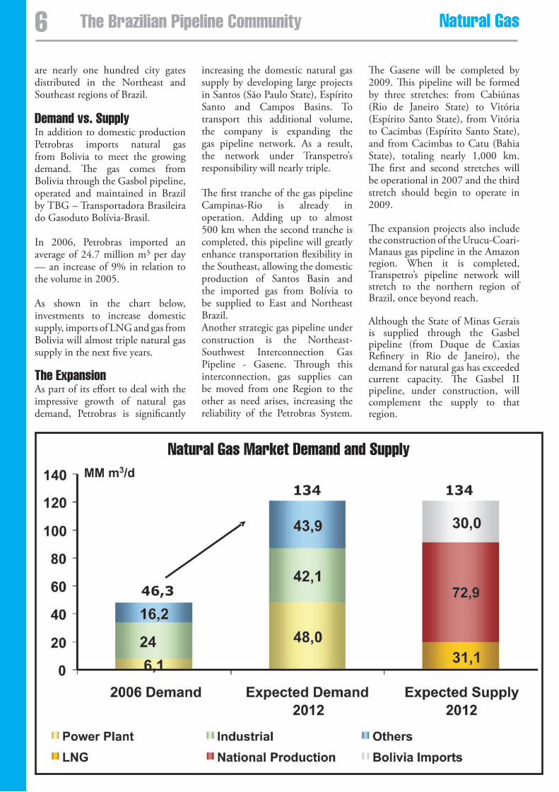
As shown in the chart below, investments to increase domestic supply, imports of LNG and gas from Bolivia will almost triple natural gas supply in the next five years.
The expansionAs part of its effort to deal with the impressive growth of natural gas demand, Petrobras is significantly
increasing the domestic natural gas supply by developing large projects in Santos (São Paulo State), Espírito Santo and Campos Basins. To transport this additional volume, the company is expanding the gas pipeline network. As a result, the network under Transpetro’s responsibility will nearly triple.
The first tranche of the gas pipeline Campinas-Rio is already in operation. Adding up to almost 500 km when the second tranche is completed, this pipeline will greatly enhance transportation flexibility in the Southeast, allowing the domestic production of Santos Basin and the imported gas from Bolívia to be supplied to East and Northeast Brazil. Another strategic gas pipeline under construction is the Northeast-Southwest Interconnection Gas Pipeline - Gasene. Through this interconnection, gas supplies can be moved from one Region to the other as need arises, increasing the reliability of the Petrobras System.
The Gasene will be completed by 2009. This pipeline will be formed by three stretches: from Cabiúnas (Rio de Janeiro State) to Vitória (Espírito Santo State), from Vitória to Cacimbas (Espírito Santo State), and from Cacimbas to Catu (Bahia State), totaling nearly 1,000 km. The first and second stretches will be operational in 2007 and the third stretch should begin to operate in 2009.
The expansion projects also include the construction of the Urucu-Coari-Manaus gas pipeline in the Amazon region. When it is completed, Transpetro’s pipeline network will stretch to the northern region of Brazil, once beyond reach.
Although the State of Minas Gerais is supplied through the Gasbel pipeline (from Duque de Caxias Refinery in Rio de Janeiro), the demand for natural gas has exceeded current capacity. The Gasbel II pipeline, under construction, will complement the supply to that region.
Natural gas Market Demand and supply
� The Brazilian Pipeline Community Natural gas
liquefied Natural gasThe introduction of LNG in the Brazilian energy scenario will constitute a new challenge as large additional volumes are processed and moved and new technologies mastered. Transpetro and Petrobras are actively seeking expertise in this area.
Regarding LNG, units for reception, storage and regasification will be installed by 2008 in floating terminals at Pecém in Ceará, and Baía de Guanabara in Rio de Janeiro, with the capacity to provide a further 20 million m³ per day to the market. The choice of regasification unit type was based in the shorter lead time required, given the need to assure a timely and flexible supply of natural gas to Brazil and in particular, to its gas-fired thermo-electrical power plants.
ConclusionAlthough natural gas has been used in Brazil since the 1960s, with the development and production of reserves in Bahia, it only became significant by 2000 when a gas pipeline connecting Brazil to Bolívia began to operate.
Given its increasing availability and environmental friendliness, natural gas demand has grown impressively over the last few years. To meet this rising demand, Petrobras has been investing heavily to improve and expand the natural gas supply network.
The expansion of the gas pipeline network and the largest processing plant will be critical to ensure that the domestic natural gas supply in Brazil will meet the growth in demand.
Petrobras will also enter in the LNG market as an importer. This, in addition to gas from Bolívia, will complement the domestic supply in attending a demand that will reach 134 million of m3 per day in 2012.
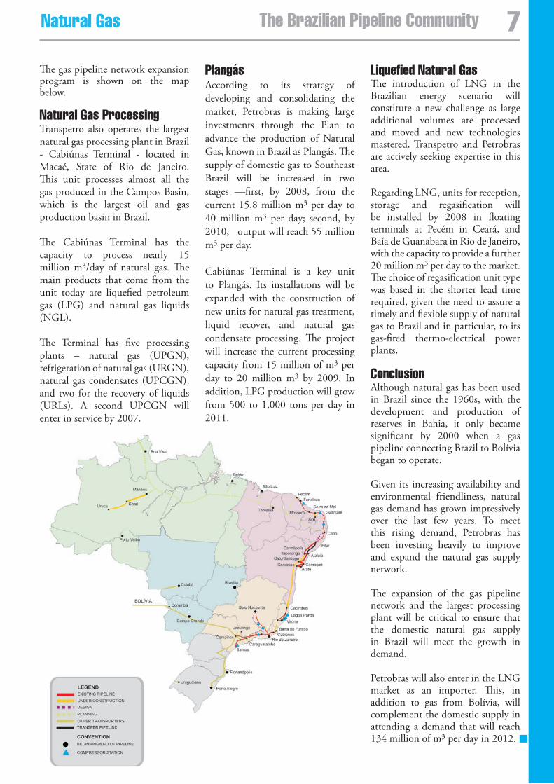
The gas pipeline network expansion program is shown on the map below.
Natural gas ProcessingTranspetro also operates the largest natural gas processing plant in Brazil - Cabiúnas Terminal - located in Macaé, State of Rio de Janeiro. This unit processes almost all the gas produced in the Campos Basin, which is the largest oil and gas production basin in Brazil.
The Cabiúnas Terminal has the capacity to process nearly 15 million m3/day of natural gas. The main products that come from the unit today are liquefied petroleum gas (LPG) and natural gas liquids (NGL).
The Terminal has five processing plants – natural gas (UPGN), refrigeration of natural gas (URGN), natural gas condensates (UPCGN), and two for the recovery of liquids (URLs). A second UPCGN will enter in service by 2007.
PlangásAccording to its strategy of developing and consolidating the market, Petrobras is making large investments through the Plan to advance the production of Natural Gas, known in Brazil as Plangás. The supply of domestic gas to Southeast Brazil will be increased in two stages —first, by 2008, from the current 15.8 million m3 per day to 40 million m3 per day; second, by 2010, output will reach 55 million m3 per day.
Cabiúnas Terminal is a key unit to Plangás. Its installations will be expanded with the construction of new units for natural gas treatment, liquid recover, and natural gas condensate processing. The project will increase the current processing capacity from 15 million of m3 per day to 20 million m3 by 2009. In addition, LPG production will grow from 500 to 1,000 tons per day in 2011.
�The Brazilian Pipeline CommunityNatural gas
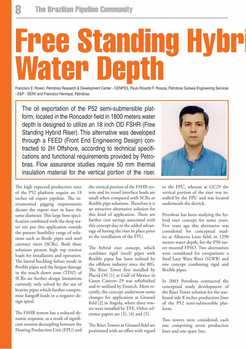
Free standing Hybrid Riser for 1800m water Depth
The oil exportation of the P52 semi-submersible plat-form, located in the Roncador field in 1800 meters water depth is designed to utilize an 18 inch OD FSHR (Free Standing Hybrid Riser). This alternative was developed through a FEED (Front End Engineering Design) con-tracted to 2H Offshore, according to technical specifi-cations and functional requirements provided by Petro-bras. Flow assurance studies require 50 mm thermal insulation material for the vertical portion of the riser.
The high expected production rates of the P52 platform require an 18 inches oil export pipeline. The in-strumented pigging requirements dictate the export riser to have the same diameter. This large bore speci-fication combined with the deep wa-ter site put this application outside the present feasibility range of solu-tions such as flexile pipes and steel catenary risers (SCRs). Both these solutions present high top tension loads for installation and operation. The lateral buckling failure mode in flexible pipes and the fatigue damage in the touch down zone (TDZ) of SCRs are further design limitations currently only solved by the use of heavier pipes which further compro-mise hangoff loads in a negative de-sign spiral.
The FSHR system has a reduced dy-namic response, as a result of signifi-cant motion decoupling between the Floating Production Unit (FPU) and
the vertical portion of the FSHR sys-tem and its vessel interface loads are small when compared with SCRs or flexible pipe solutions. Therefore it is an attractive alternative solution for this kind of application. There are further cost savings associated with this concept due to the added advan-tage of having the riser in place prior to the installation of the FPU.
The hybrid riser concept, which combines rigid (steel) pipes with flexible pipes has been utilized by the offshore industry since the 80’s. The Riser Tower first installed by Placid Oil [1] at Gulf of Mexico in Green Canyon 29 was refurbished and re¬utilized by Enserch. More re-cently, the concept underwent some changes for application at Girassol field [2] in Angola, where three tow-ers were installed by TFE. Other ref-erence papers are [3], [4] and [5].
The Riser Towers at Girassol field are positioned with an offset with regard
to the FPU, whereas at GC29 the vertical portion of the riser was in-stalled by the FPU and was located underneath the derrick.
Petrobras has been studying the hy-brid riser concept for some years. Five years ago this alternative was considered for conceptual stud-ies at Albacora Leste field, in 1290 meters water depth, for the P50 tur-ret moored FPSO. Two alternatives were considered for comparison: a Steel Lazy Wave Riser (SLWR) and one concept combining rigid and flexible pipes.
In 2003 Petrobras contracted the conceptual study development of the Riser Tower solution for the star-board side 8 inches production lines of the P52 semi-submersible plat-form.
Two towers were considered, each one comprising seven production lines and one spare line.
8 The Brazilian Pipeline Community
Francisco E. Roveri, Petrobras Research & Development Center - CENPES, Paulo Ricardo F. Pessoa, Petrobras Subsea Engineering Services - E&P - SERV and Francisco Henrique, Petrobras
Free standing Hybrid Riser for 1800m water Depth
Five water and gas injection monobore FSHRs (10 to 12 inches) have recently been installed in West Africa offshore Angola, at Kizomba field in about 1200 meters water depth. The design of these risers has some key differences to the con-cept presented in this paper, each of which offers different design and op-erational advantages.
Two years ago Petrobras contracted 2H to provide the feasibility studies of an export oil FSHR to be utilized at P40. Due to changes in field de-velopment planning, the study was further developed for the P51 and P52 semi¬submersible platforms.
system Description The FSHR design may have a number of variants. The one described below is the base case considered for P52 oil export riser to be installed from a MODU due to the availability of such vessels already under contract at Campos Basin. The required de-sign life is 25 years.
The FSHR consists of a single near vertical steel pipe connected to a foundation system at the mud line region. The riser is tensioned by means of a buoyancy can, which is mechanically connected to the top of the vertical pipe. The riser pipe passes through the central stem of the buoyancy can, which is located below the sea level, therefore beyond
the zone of influence of wave and high current. A gooseneck assem-bly is located on top of the buoy-ancy can. A flexible jumper links the gooseneck to the FPU and signifi-cantly decouples the vertical part of the FSHR from the vessel motions.
The foundation may typically be off-set from the FPU by more than 200 meters, depending on the optimiza-tion study, which takes into consid-eration the following parameters: (a) flexible jumper length, (b) riser base offset, (c) buoyancy can depth, (d) net upthrust provided by the buoy-ancy can and (e) the azimuth of the FSHR system.
The FSHR goes from the #1 hangoff slot at P52 to the Pipeline End Ter-mination (PLET) located near the riser base. The lower end of the verti-cal part interfaces with a stress joint. Below the stress joint there is the offtake spool, which connects to the foundation by means of a hydraulic connector. A rigid base jumper con-nects the mandrels located at the offtake spool and PLET, providing the link between the FSHR and the pipeline. The foundation pile will be drilled and grouted.
The tension is given by the upthrust provided by the nitrogen filled buoyancy can located on top of the vertical pipe. The vertical pipe shall
be kept always in tension in order to keep the FSHR stable for all the load cases.
The riser pipe passes through a in-ner 36 inches OD stem within the buoyancy can, and is guided within the stem by centralizers. Where the riser pipe is subject to high bending loads such as the keel ball centralizer on the buoyancy can, taper joints are used to reduce the stress in the riser pipe. The buoyancy can is secured to the riser pipe at the top of the can by means of a bolted connection.
At the top of the free-standing riser is the gooseneck assembly. This as-sembly consists primarily of the gooseneck and an ROV actuated hy-draulic connector which allows the gooseneck and flexible jumper to be installed separately from the vertical section of the riser. The gooseneck assembly also includes a cross-brace tied to a support spool in order to provide support against the load-ing applied to the gooseneck from the flexible jumper. Attached to the gooseneck is the flexible jumper. The flexible jumper connects the free-standing section of the riser system to the vessel, and includes bend stiff-eners to ensure that the range of ro-tations experienced at the end con-nections do not damage the jumper due to low radius of curvature. The flexible jumper has enough compli-ance such that the vessel motions
Two years ago Petrobras contracted 2H to provide the feasibility studies of an export oil FSHR to be utilized at P40. Due to changes in field
development planning, the study was further developed for the P51 and P52 semi-submersible platforms.
�The Brazilian Pipeline Community
and offsets are substantially decou-pled from the vertical portion of the FSHR system, and consequently the wave-induced dynamic response of the free standing riser is low.
Differences from existing design The position of the gooseneck in relation to the buoyancy can is the main difference between the West African and P52 FSHR designs. In the earlier design, the gooseneck is positioned below the buoyancy can and the vertical riser is tensioned by the can via a flexible linkage or chain.
This arrangement simplifies the interface between the buoyancy can and vertical riser, and allows pre-assembly of the flexible jumper to the gooseneck before deployment of the vertical riser. However, in the event of flexible jumper replacement or repair, an elaborate jumper disconnection system needs to be employed below the buoyancy can.
Positioning the gooseneck at the top of the buoyancy can allows for inde-pendent installation of vertical riser and flexible jumper. A flexible pipe installation vessel can install the flex-ible jumper at a time of convenience. This minimizes the risk of damage to
the flexible jumper during installa-tion as the procedure is similar to that of a shallow water flexible riser with the first end at the top of the buoyancy can. This design also fa-cilitates and minimizes the time for
Table 1 - FSHR main characteristics
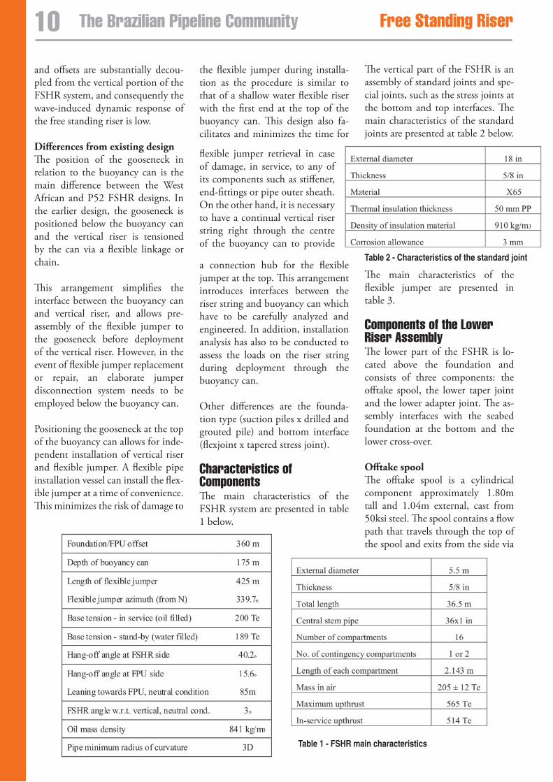
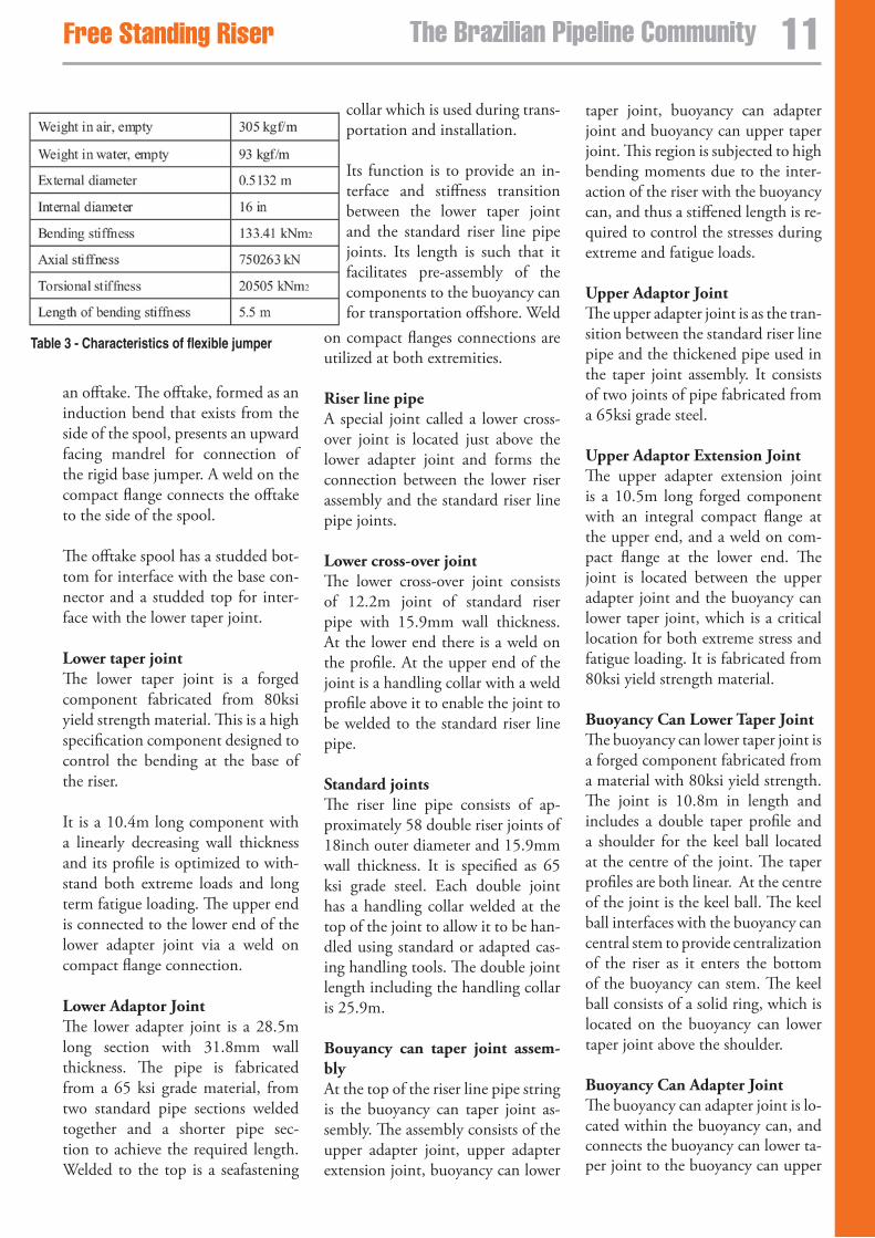
The vertical part of the FSHR is an assembly of standard joints and spe-cial joints, such as the stress joints at the bottom and top interfaces. The main characteristics of the standard joints are presented at table 2 below.
flexible jumper retrieval in case of damage, in service, to any of its components such as stiffener, end-fittings or pipe outer sheath. On the other hand, it is necessary to have a continual vertical riser string right through the centre of the buoyancy can to provide
a connection hub for the flexible jumper at the top. This arrangement introduces interfaces between the riser string and buoyancy can which have to be carefully analyzed and engineered. In addition, installation analysis has also to be conducted to assess the loads on the riser string during deployment through the buoyancy can.
Other differences are the founda-tion type (suction piles x drilled and grouted pile) and bottom interface (flexjoint x tapered stress joint).
Characteristics of Components The main characteristics of the FSHR system are presented in table 1 below.
Table 2 - Characteristics of the standard joint
The main characteristics of the flexible jumper are presented in table 3.
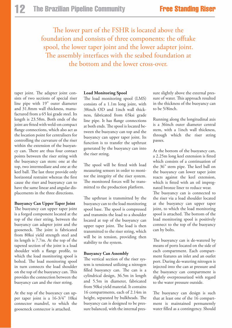
Components of the lower Riser assembly The lower part of the FSHR is lo-cated above the foundation and consists of three components: the offtake spool, the lower taper joint and the lower adapter joint. The as-sembly interfaces with the seabed foundation at the bottom and the lower cross-over.
Offtake spool The offtake spool is a cylindrical component approximately 1.80m tall and 1.04m external, cast from 50ksi steel. The spool contains a flow path that travels through the top of the spool and exits from the side via
10 The Brazilian Pipeline Community Free standing Riser Free standing Riser
taper joint, buoyancy can adapter joint and buoyancy can upper taper joint. This region is subjected to high bending moments due to the inter-action of the riser with the buoyancy can, and thus a stiffened length is re-quired to control the stresses during extreme and fatigue loads.
Upper Adaptor Joint The upper adapter joint is as the tran-sition between the standard riser line pipe and the thickened pipe used in the taper joint assembly. It consists of two joints of pipe fabricated from a 65ksi grade steel.
Upper Adaptor Extension Joint The upper adapter extension joint is a 10.5m long forged component with an integral compact flange at the upper end, and a weld on com-pact flange at the lower end. The joint is located between the upper adapter joint and the buoyancy can lower taper joint, which is a critical location for both extreme stress and fatigue loading. It is fabricated from 80ksi yield strength material.
Buoyancy Can Lower Taper Joint The buoyancy can lower taper joint is a forged component fabricated from a material with 80ksi yield strength. The joint is 10.8m in length and includes a double taper profile and a shoulder for the keel ball located at the centre of the joint. The taper profiles are both linear. At the centre of the joint is the keel ball. The keel ball interfaces with the buoyancy can central stem to provide centralization of the riser as it enters the bottom of the buoyancy can stem. The keel ball consists of a solid ring, which is located on the buoyancy can lower taper joint above the shoulder.
Buoyancy Can Adapter Joint The buoyancy can adapter joint is lo-cated within the buoyancy can, and connects the buoyancy can lower ta-per joint to the buoyancy can upper
Table 3 - Characteristics of flexible jumper
an offtake. The offtake, formed as an induction bend that exists from the side of the spool, presents an upward facing mandrel for connection of the rigid base jumper. A weld on the compact flange connects the offtake to the side of the spool.
The offtake spool has a studded bot-tom for interface with the base con-nector and a studded top for inter-face with the lower taper joint.
Lower taper joint The lower taper joint is a forged component fabricated from 80ksi yield strength material. This is a high specification component designed to control the bending at the base of the riser.
It is a 10.4m long component with a linearly decreasing wall thickness and its profile is optimized to with-stand both extreme loads and long term fatigue loading. The upper end is connected to the lower end of the lower adapter joint via a weld on compact flange connection.
Lower Adaptor Joint The lower adapter joint is a 28.5m long section with 31.8mm wall thickness. The pipe is fabricated from a 65 ksi grade material, from two standard pipe sections welded together and a shorter pipe sec-tion to achieve the required length. Welded to the top is a seafastening
collar which is used during trans-portation and installation.
Its function is to provide an in-terface and stiffness transition between the lower taper joint and the standard riser line pipe joints. Its length is such that it facilitates pre-assembly of the components to the buoyancy can for transportation offshore. Weld
on compact flanges connections are utilized at both extremities.
Riser line pipe A special joint called a lower cross-over joint is located just above the lower adapter joint and forms the connection between the lower riser assembly and the standard riser line pipe joints.
Lower cross-over joint The lower cross-over joint consists of 12.2m joint of standard riser pipe with 15.9mm wall thickness. At the lower end there is a weld on the profile. At the upper end of the joint is a handling collar with a weld profile above it to enable the joint to be welded to the standard riser line pipe.
Standard joints The riser line pipe consists of ap-proximately 58 double riser joints of 18inch outer diameter and 15.9mm wall thickness. It is specified as 65 ksi grade steel. Each double joint has a handling collar welded at the top of the joint to allow it to be han-dled using standard or adapted cas-ing handling tools. The double joint length including the handling collar is 25.9m. Bouyancy can taper joint assem-bly At the top of the riser line pipe string is the buoyancy can taper joint as-sembly. The assembly consists of the upper adapter joint, upper adapter extension joint, buoyancy can lower
11The Brazilian Pipeline CommunityFree standing Riser Free standing Riser
taper joint. The adapter joint con-sists of two sections of special riser line pipe with 19” outer diameter and 31.8mm wall thickness, manu-factured from a 65 ksi grade steel. Its length is 23.58m. Both ends of the joint are fitted with weld-on compact flange connections, which also act as the location point for centralisers for controlling the curvature of the riser within the extension of the buoyan-cy can. There are thus four contact points between the riser string with the buoyancy can stem: one at the top, two intermediate and one at the keel ball. The last three provide only horizontal restraint whereas the first cause the riser and buoyancy can to have the same linear and angular dis-placements in the three directions. Buoyancy Can Upper Taper Joint The buoyancy can upper taper joint is a forged component located at the top of the riser string, between the buoyancy can adapter joint and the gooseneck. The joint is fabricated from 80ksi yield strength steel and its length is 7.7m. At the top of the tapered section of the joint is a load shoulder with a flange profile, to which the load monitoring spool is bolted. The load monitoring spool in turn connects the load shoulder on the top of the buoyancy can. This provides the connection between the buoyancy can and the riser string. At the top of the buoyancy can up-per taper joint is a 16-3/4” 10ksi connector mandrel, to which the gooseneck connector is attached.
Load Monitoring Spool The load monitoring spool (LMS) consists of a 1.1m long joint, with 38inch OD and 1inch wall thick-ness, fabricated from 65ksi grade line pipe. It has flange connections at both ends. The spool is located be-tween the buoyancy can top and the buoyancy can upper taper joint. Its function is to transfer the upthrust generated by the buoyancy can into the riser string.
The spool will be fitted with load measuring sensors in order to moni-tor the integrity of the riser system. The monitored forces will be trans-mitted to the production platform.
The upthrust is transmitted by the buoyancy can to the load monitoring spool base. The spool is compressed and transmits the load to a shoulder located at top of the buoyancy can upper taper joint. The load is then transmitted to the riser string, which will be in tension, providing then stability to the system.
Buoyancy Can Assembly The vertical section of the riser sys-tem is tensioned utilizing a nitrogen filled buoyancy can. The can is a cylindrical design, 36.5m in length and 5.5m in diameter, fabricated from 50ksi yield material. It contains 16 compartments, each of 2.14m in height, separated by bulkheads. The buoyancy can is designed to be pres-sure balanced, with the internal pres-
sure slightly above the external pres-sure of water. This approach resulted in the thickness of the buoyancy can to be 5/8inch.
Running along the longitudinal axis is a 36inch outer diameter central stem, with a 1inch wall thickness, through which the riser string passes.
At the bottom of the buoyancy can, a 2.25m long keel extension is fitted which consists of a continuation of the 36” stem pipe. The keel ball on the buoyancy can lower taper joint reacts against the keel extension, which is fitted with an oil impreg-nated bronze liner to reduce wear. The buoyancy can is connected to the riser via a load shoulder located at the buoyancy can upper taper joint, to which the load monitoring spool is attached. The bottom of the load monitoring spool is positively connect to the top of the buoyancy can by bolts.
The buoyancy can is de-watered by means of ports located on the side of each compartment. Each compart-ment features an inlet and an outlet port. During de-watering nitrogen is injected into the can at pressure and the buoyancy can compartment is slightly overpressurized with regard to the water pressure outside.
The buoyancy can design is such that at least one of the 16 compart-ment is maintained permanently water filled as a contingency. Should
The lower part of the FSHR is located above the foundation and consists of three components: the offtake spool, the lower taper joint and the lower adapter joint. The assembly interfaces with the seabed foundation at
the bottom and the lower cross-over.
12 The Brazilian Pipeline Community Free standing Riser Free standing Riser
one compartment fail in service, a contingency compartment can be de-watered in order to keep the op-erational tension in the riser string. The difference between the internal and external pressures corresponds to the length of each compartment.
Gooseneck assembly The components located at the up-per part of the system are described hereinafter.
Hydraulic Connector A 16-3/4inch-10ksi hydraulic con-nector is utilized to attach the goose-neck to the riser string. The con-nector is hydraulically locked, and actuated via an ROV stab. The role of the connector is to allow the flexible jumper to be retrieved during service should the jumper be required to be fixed or replaced. Gooseneck At the top of the system is the goose-neck, which provides the change from the vertical section to the flex-ible jumper to the production plat-form. The gooseneck is a curved pipe, formed using induction bend-ing with a 3D minimum bend radi-us. The lower end of the gooseneck is attached to the gooseneck support spool, which in turn is connected to the API flange on the connector. Gooseneck support The gooseneck is braced by a struc-tural beam which connects between the upper end of the gooseneck and the gooseneck support spool at the lower end of the gooseneck. The support brace and support spool provide a load path for the loading applied to the riser from the flexible jumper, and prevent overstressing of the gooseneck. Flexible Jumper Assembly The flexible jumper assembly consists of the flexible jumper, end termina-tions and bend stiffeners at both the
FSHR end and the production plat-form end of the jumper.
Flexible Jumper The flexible jumper is a 16inch in-ternal diameter, 425 meters long and rated for 3000 psi design pres-sure and 90ºC design temperature.
End Terminations At both ends of the flexible jump-er are end termination assemblies as specified by the flexible jumper manufacturer. At both ends of the jumper the termination is required to interface with a compact flange connection.
Bend Stiffeners Bend stiffeners are located at both ends of the flexible jumper. Each stiffener is designed to meet the pre-dicted range of jumper rotations at the both the gooseneck attachment and at the production platform con-nection. The bend stiffeners are de-signed and manufactured according to the details specified by the flexible jumper manufacturer.
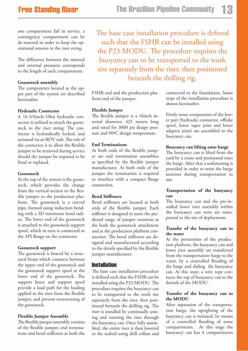
InstallationThe base case installation procedure is defined such that the FSHR can be installed using the P23 MODU. The procedure requires the buoyancy can to be transported to the work site separately from the riser, then posi-tioned beneath the drilling rig. The riser is installed by continually join-ing and running the riser through the buoyancy can. Once fully assem-bled, the entire riser is then lowered to the seabed using drill collars and
connected to the foundation. Some steps of the installation procedure is shown hereinafter.
Firstly some components of the low-er part (hydraulic connector, offtake spool, lower taper joint and lower adaptor joint) are assembled to the buoyancy can.
Buoyancy can lifting onto barge The buoyancy can is lifted from the yard by a crane and positioned onto the barge. After that a seafastening is provided in order to resist the barge motions during transportation to site.
Transportation of the buoyancy can The buoyancy can and the pre-in-stalled lower riser assembly within the buoyancy can stem are trans-ported to the site of deployment. Transfer of the buoyancy can to the water At the proximities of the produc-tion platform, the buoyancy can and lower riser assembly are transferred from the transportation barge to the water, by a controlled flooding of the barge and sliding the buoyancy can. At this state, a wire rope con-nects the top of buoyancy can to the derrick of the MODU. Transfer of the buoyancy can to the MODU After separation of the transporta-tion barge, the uprighting of the buoyancy can is initiated, by means of a controlled flooding of some compartments. At this stage the buoyancy can has 4 compartments
The base case installation procedure is defined such that the FSHR can be installed using
the P23 MODU. The procedure requires the buoyancy can to be transported to the work site separately from the riser, then positioned
beneath the drilling rig.
13The Brazilian Pipeline CommunityFree standing Riser Free standing Riser
nitrogen filled, thus having overall negative buoyancy. The keel haul-ing process is then initiated, and the weight of the buoyancy can is trans-ferred gradually to the derrick of the MODU.
Buoyancy can beneath the MODU At the end of the keel hauling proc-ess, the buoyancy can will be beneath the MODU derrick, still supported by the wire rope connected to the platform.
Buoyancy can supported by ten-sioners After that the buoyancy can is lifted until its upper end is approximately 0.5m below the Lower Deck of the MODU and its weight is transferred from the keel hauling wire rope to the MODU drilling riser tensioning system. Lowering of riser joints The procedure for deploying the ris-er joints is shown hereinafter. Lower Cross Over connection The Lower Cross Over Joint is the first connection to be made to the pre-installed components of the FSHR system within the stem of the buoyancy can. After the connection is made, the seafastening collar at the top of the buoyancy can is removed.
Lowering of the Lower Cross Over Joint and first Standard joint After the first connection aforemen-tioned is made, the Lower Cross Over and the first Standard joints are deployed, such as the lower ex-tremity of the string is approximate-ly 40 meters below the buoyancy can lower end.
Lowering of the buoyancy can for deployment of the remaining joints The buoyancy can is then lowered until its upper end is placed at the pontoon deck level. The buoyancy can is lowered by supporting the can on four padeyes on short chains, then transferring the load to the
remaining four chains with longer chains using the full stroke range of the tensioners. Extension chains are then added to the 4 tensioners with shorter chains such that all eight tensioners are used. The buoyancy can upper end is connected by hori-zontal wire ropes to pulleys located in strong points at the pontoon level and to winches at the deck, such as to control the horizontal motions of the can.
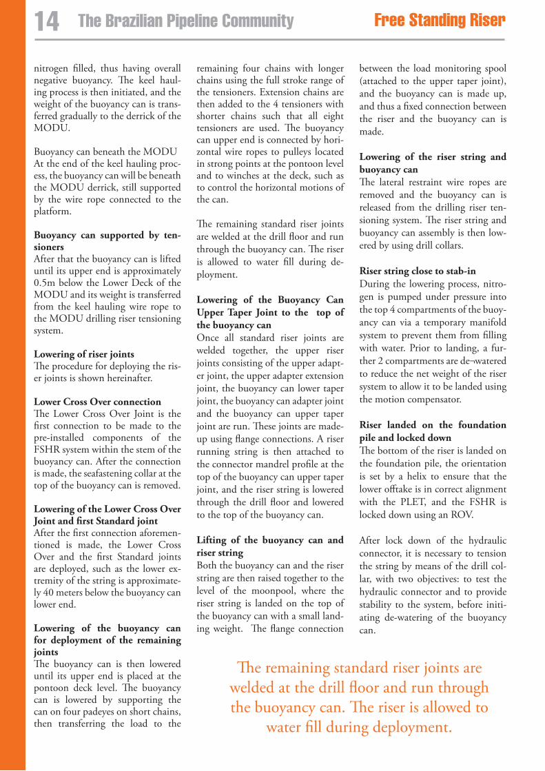
The remaining standard riser joints are welded at the drill floor and run through the buoyancy can. The riser is allowed to water fill during de-ployment. Lowering of the Buoyancy Can Upper Taper Joint to the top of the buoyancy can Once all standard riser joints are welded together, the upper riser joints consisting of the upper adapt-er joint, the upper adapter extension joint, the buoyancy can lower taper joint, the buoyancy can adapter joint and the buoyancy can upper taper joint are run. These joints are made-up using flange connections. A riser running string is then attached to the connector mandrel profile at the top of the buoyancy can upper taper joint, and the riser string is lowered through the drill floor and lowered to the top of the buoyancy can.
Lifting of the buoyancy can and riser string Both the buoyancy can and the riser string are then raised together to the level of the moonpool, where the riser string is landed on the top of the buoyancy can with a small land-ing weight. The flange connection
between the load monitoring spool (attached to the upper taper joint), and the buoyancy can is made up, and thus a fixed connection between the riser and the buoyancy can is made. Lowering of the riser string and buoyancy can The lateral restraint wire ropes are removed and the buoyancy can is released from the drilling riser ten-sioning system. The riser string and buoyancy can assembly is then low-ered by using drill collars. Riser string close to stab-in During the lowering process, nitro-gen is pumped under pressure into the top 4 compartments of the buoy-ancy can via a temporary manifold system to prevent them from filling with water. Prior to landing, a fur-ther 2 compartments are de¬watered to reduce the net weight of the riser system to allow it to be landed using the motion compensator.
Riser landed on the foundation pile and locked down The bottom of the riser is landed on the foundation pile, the orientation is set by a helix to ensure that the lower offtake is in correct alignment with the PLET, and the FSHR is locked down using an ROV. After lock down of the hydraulic connector, it is necessary to tension the string by means of the drill col-lar, with two objectives: to test the hydraulic connector and to provide stability to the system, before initi-ating de-watering of the buoyancy can.
The remaining standard riser joints are welded at the drill floor and run through the buoyancy can. The riser is allowed to
water fill during deployment.
14 The Brazilian Pipeline Community Free standing Riser Free standing Riser
De-watering of the buoyancy can After lock down of the hydraulic connector, the stability of the system is partly due to the tension applied by the drill collar string. The ROV starts the de-watering process of the buoyancy can compartments by means of injecting nitrogen. As long as the de-watering proceeds, the ten-sion applied by the MODU is de-creased, such as to keep the resulting tension approximately constant. At the end of the process, the tension provided by the buoyancy can allows the riser to free-stand and the drill collar string is disconnected from the top of the buoyancy can. After conclusion of this process the flexible jumper is installed. The in-stallation of the vertical section of the FSHR may take place before ar-rival of the production platform.
Connection of the gooseneck to the mandrel at riser top The gooseneck attached to the flex-ible jumper end at the buoyancy can side is deployed by a Laying Support Vessel (LSV) and connected to the mandrel of the Buoyancy Can Up-per Taper Joint. An ROV actuates a hydraulic connector.
LSV installing the flexible jumper The gooseneck and flexible jumper are first attached to the riser using the LSV, and the flexible jumper then un-reeled and pulled-in to the slot on the P52 platform.
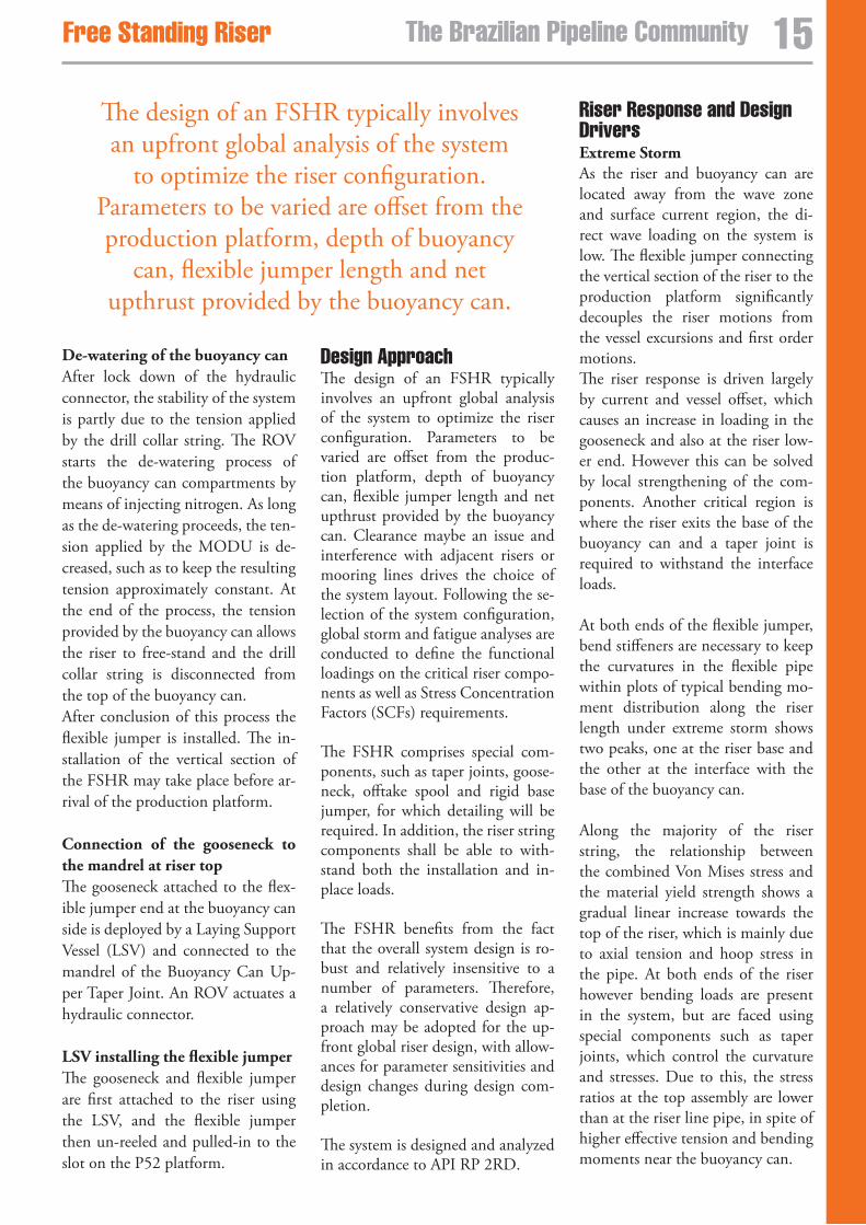
Design approachThe design of an FSHR typically involves an upfront global analysis of the system to optimize the riser configuration. Parameters to be varied are offset from the produc-tion platform, depth of buoyancy can, flexible jumper length and net upthrust provided by the buoyancy can. Clearance maybe an issue and interference with adjacent risers or mooring lines drives the choice of the system layout. Following the se-lection of the system configuration, global storm and fatigue analyses are conducted to define the functional loadings on the critical riser compo-nents as well as Stress Concentration Factors (SCFs) requirements.
The FSHR comprises special com-ponents, such as taper joints, goose-neck, offtake spool and rigid base jumper, for which detailing will be required. In addition, the riser string components shall be able to with-stand both the installation and in-place loads.
The FSHR benefits from the fact that the overall system design is ro-bust and relatively insensitive to a number of parameters. Therefore, a relatively conservative design ap-proach may be adopted for the up-front global riser design, with allow-ances for parameter sensitivities and design changes during design com-pletion.
The system is designed and analyzed in accordance to API RP 2RD.
Riser Response and Design Drivers Extreme Storm As the riser and buoyancy can are located away from the wave zone and surface current region, the di-rect wave loading on the system is low. The flexible jumper connecting the vertical section of the riser to the production platform significantly decouples the riser motions from the vessel excursions and first order motions. The riser response is driven largely by current and vessel offset, which causes an increase in loading in the gooseneck and also at the riser low-er end. However this can be solved by local strengthening of the com-ponents. Another critical region is where the riser exits the base of the buoyancy can and a taper joint is required to withstand the interface loads.
At both ends of the flexible jumper, bend stiffeners are necessary to keep the curvatures in the flexible pipe within plots of typical bending mo-ment distribution along the riser length under extreme storm shows two peaks, one at the riser base and the other at the interface with the base of the buoyancy can.
Along the majority of the riser string, the relationship between the combined Von Mises stress and the material yield strength shows a gradual linear increase towards the top of the riser, which is mainly due to axial tension and hoop stress in the pipe. At both ends of the riser however bending loads are present in the system, but are faced using special components such as taper joints, which control the curvature and stresses. Due to this, the stress ratios at the top assembly are lower than at the riser line pipe, in spite of higher effective tension and bending moments near the buoyancy can.
The design of an FSHR typically involves an upfront global analysis of the system
to optimize the riser configuration. Parameters to be varied are offset from the production platform, depth of buoyancy
can, flexible jumper length and net upthrust provided by the buoyancy can.
15The Brazilian Pipeline CommunityFree standing Riser Free standing Riser
Along the vertical section of the FSHR, the stresses are practically static, barely affected by quasi-static loads (vessel static offsets and cur-rent) or dynamic loads (direct wave load and first and second order mo-tions). The design of deeper compo-nents, such as the lower taper joint, is driven by quasi¬static loads. The upper riser component designs are dictated by both quasi-static and dy-namic loads.
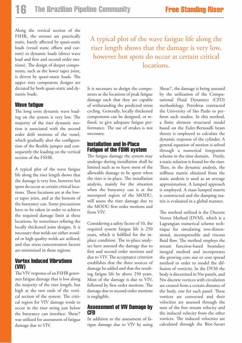
wave fatigue The long term dynamic wave load-ing on the system is very low. The majority of the riser dynamic mo-tion is associated with the second order drift motions of the vessel, which gradually alter the configura-tion of the flexible jumper and con-sequently the loading on the vertical section of the FSHR.
A typical plot of the wave fatigue life along the riser length shows that the damage is very low, however hot spots do occur at certain critical loca-tions. These locations are at the low-er taper joint, and at the bottom of the buoyancy can. Some precautions have to be taken in order to achieve the required damage limit at these locations, by sometimes refining the locally thickened joint designs. It is necessary that welds are either avoid-ed or high quality welds are utilized, and that stress concentration factors are minimized in these regions.
vortex Induced vibrations (vIv) The VIV response of an FSHR gener-ates fatigue damage that is low along the majority of the riser length, but high at the two ends of the verti-cal section of the system. The criti-cal region for VIV damage tends to occur in the riser string just below the buoyancy can interface. Shear7 was utilized for assessment of fatigue damage due to VIV.
It is necessary to design the compo-nents at the locations of peak fatigue damage such that they are capable of withstanding the predicted stress cycling. Generally, locally thickened components can be designed, or re-fined, to give adequate fatigue per-formance. The use of strakes is not necessary.
Installation and In-Place Fatigue of the FsHR system The fatigue damage the system may undergo during installation shall be limited such as to leave most of the allowable damage to be spent when the riser is in-place. The installation analysis, mainly for the situation when the buoyancy can is at the moonpool region of the MODU, will assess the riser damage due to the MODU first order motions and from VIV.
Considering a safety factor of 10, the required system fatigue life is 250 years, which is fulfilled for the in-place condition. The in-place analy-ses have assessed the damage due to first and second order motions and due to VIV. The acceptance criterion establishes that the three sources of damage be added and that the result-ing fatigue life be above 250 years. Most of the damage is due to VIV, followed by first order motions. The damage due to second order motions is negligible.
assessment of vIv Damage by CFD In addition to the assessment of fa-tigue damage due to VIV by using
Shear7, the damage is being assessed by the utilization of the Compu-tational Fluid Dynamics (CFD) methodology. Petrobras contracted the University of São Paulo to per-form such studies. In this method, a finite element structural model based on the Euler-Bernoulli beam theory is employed to calculate the dynamic response of the cylinder. A general equation of motion is solved through a numerical integration scheme in the time domain. Firstly, a static solution is found for the riser. Then, in the dynamic analysis, the stiffness matrix obtained from the static analysis is used as an average approximation. A lumped approach is employed. A mass lumped matrix is constructed and the damping ma-trix is evaluated in a global manner.
The method utilized is the Discrete Vortex Method (DVM), which is a Lagrangian numerical scheme tech-nique for simulating two-dimen-sional, incompressible and viscous fluid flow. The method employs the stream function-based boundary integral method and incorporates the growing core size or core spread method in order to model the dif-fusion of vorticity. In the DVM the body is discretized in Nw panels, and Nw discrete vortices with circulation are created from a certain distance of the body, one for each panel. These vortices are convected and their velocities are assessed through the sum of the free stream velocity and the induced velocity from the other vortices. The induced velocities are calculated through the Biot-Savart
A typical plot of the wave fatigue life along the riser length shows that the damage is very low, however hot spots do occur at certain critical
locations.
1� The Brazilian Pipeline Community Free standing Riser Free standing Riser
law. Forces on the body are calcu-lated integrating the pressures and viscous stresses. Viscous stresses are evaluated from the velocities in the near-wall region, and the pressure distribution is calculated relating the vorticity flux on the wall to the gen-eration of circulation.
Model TestThe installation phase is a critical issue for the design of the FSHR, mainly due to utilization of a MODU for deployment. The op-erating window is narrowed due to buoyancy can motions at the moon-pool region, caused by the action of current and waves, and the result-ing riser forces at the interfaces with both the buoyancy can bottom and rotary table.
Results from numerical analysis as-sessment show that the allowable sea states for some stages of the deploy-ment are significantly milder when compared to the weather window of previous deployments of subsea hardware, such as manifolds, already performed by Petrobras utilizing MODU. Modeling the entire FSHR system in 1800 m water depth would re-quire a very small scale (approxi-mately 1:180) and some important effects could be not well represented. Therefore it was decided to test the system behavior only during instal-lation. A model test at the scale of 1:28.7 representing the buoyancy can, MODU and riser string was constructed and tested at Marintek. The objective was to corroborate the results of numerical calculations.
Three phases were simulated: (a) buoyancy can free floating, (b) keel hauling of the buoyancy can and (c) buoyancy can at the moonpool region, suspended either by wire rope at the derrick or by the drilling riser tensioning system, and the ris-er string passing through the stem.
Two riser lengths were considered: initial and total length. For the last, it was necessary to truncate the riser string.
ConclusionsIn the FSHR design concept, the location of the buoyancy can below high current and wave zone, and the use of the flexible jumper to signifi-cantly decouple vessel motions from the vertical riser greatly reduces the system dynamic response, resulting in a robust riser design particularly suited to deep water applications.
The design is relatively insensitive to severe environmental loading and non-heave optimized host vessels when compared to SCRs and flex-ible risers. The robustness allows the riser to be conservatively analysed, and allowances for design changes and uncertainties to be included up-front in the design process, thus giv-ing greater confidence in the overall system design.
For engineering, procurement and construction (EPC) contractors not having a suitable vessel, or unable to mobilize their vessels to install the FSHR, the ability to use a MODU as the installation vessel could prove to be an attractive alternative.
It can be said that the FSHR concept extends the reach of deep water riser feasibility as it avoids the main tech-nical problems faced by the other so-lutions, and arguably, it may be the only proven riser concept feasible for deep water large bore applications. References1. Fisher, E. A., Berner, P.C., 1988, “Non-Integral Production Riser for the Green Canyon Block 29 De-velopment”, Offshore Technology Conference, paper 5846, Houston – USA
2. Rouillon, Jacky, 2002, “Girassol -The Umbilicals and Flowlines - Presentation and Challenges”, paper 14171, Houston - USA
3. Déserts, des L., 2000, “Hybrid Riser for Deepwater Offshore Af-rica”, Offshore Technology Confer-ence, paper 11875, Houston – USA
4. Hatton, S., Lim, F., 1999, “Third Generation Hybrid Risers”, World Wide Deepwater Technologies, Lon-don – UK
5. S. Hatton, J. McGrail and D. Wal-ters, 2002, “Recent Developments in Free Standing Riser Technology”, 3rd Workshop on Subsea Pipelines, Rio de Janeiro - Brazil
The installation phase is a critical issue for the design of the FSHR, mainly due to utilization of a MODU for deployment. The operating window is narrowed due to buoyancy can
motions at the moonpool region, caused by the action of current and waves, and the resulting
riser forces at the interfaces with both the buoyancy can bottom and rotary table.
1�The Brazilian Pipeline CommunityFree standing Riser Free standing Riser
Improving pipeline performanceThe PRODUT program helps Petrobras improve operational reliability, increase capacity, and maintain environmental safety.
Ney Passos, Petrobras Brasil S.A., Rio de Janeiro, Brazil
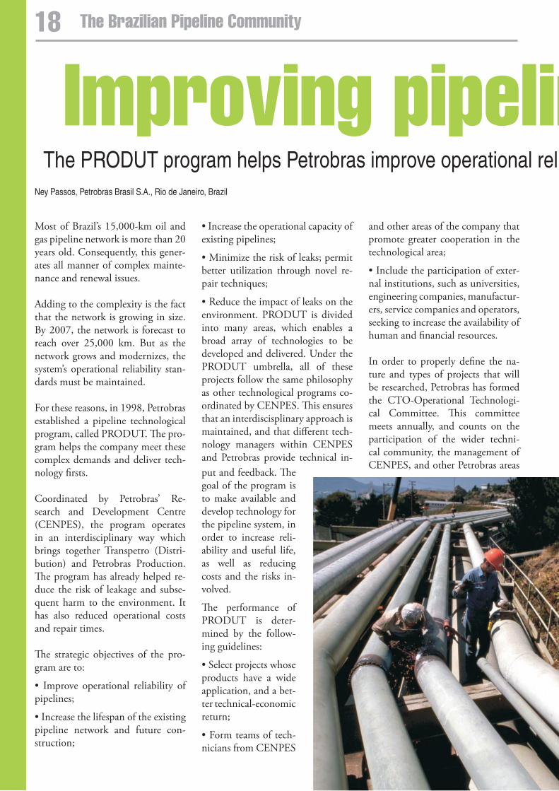
Most of Brazil’s 15,000-km oil and gas pipeline network is more than 20 years old. Consequently, this gener-ates all manner of complex mainte-nance and renewal issues.
Adding to the complexity is the fact that the network is growing in size. By 2007, the network is forecast to reach over 25,000 km. But as the network grows and modernizes, the system’s operational reliability stan-dards must be maintained.
For these reasons, in 1998, Petrobras established a pipeline technological program, called PRODUT. The pro-gram helps the company meet these complex demands and deliver tech-nology firsts.
Coordinated by Petrobras’ Re-search and Development Centre (CENPES), the program operates in an interdisciplinary way which brings together Transpetro (Distri-bution) and Petrobras Production. The program has already helped re-duce the risk of leakage and subse-quent harm to the environment. It has also reduced operational costs and repair times.
The strategic objectives of the pro-gram are to:
• Improve operational reliability of pipelines;
• Increase the lifespan of the existing pipeline network and future con-struction;
• Increase the operational capacity of existing pipelines;
• Minimize the risk of leaks; permit better utilization through novel re-pair techniques;
• Reduce the impact of leaks on the environment. PRODUT is divided into many areas, which enables a broad array of technologies to be developed and delivered. Under the PRODUT umbrella, all of these projects follow the same philosophy as other technological programs co-ordinated by CENPES. This ensures that an interdiscisplinary approach is maintained, and that different tech-nology managers within CENPES and Petrobras provide technical in-
and other areas of the company that promote greater cooperation in the technological area;
• Include the participation of exter-nal institutions, such as universities, engineering companies, manufactur-ers, service companies and operators, seeking to increase the availability of human and financial resources.
In order to properly define the na-ture and types of projects that will be researched, Petrobras has formed the CTO-Operational Technologi-cal Committee. This committee meets annually, and counts on the participation of the wider techni-cal community, the management of CENPES, and other Petrobras areas
put and feedback. The goal of the program is to make available and develop technology for the pipeline system, in order to increase reli-ability and useful life, as well as reducing costs and the risks in-volved.
The performance of PRODUT is deter-mined by the follow-ing guidelines:
• Select projects whose products have a wide application, and a bet-ter technical-economic return;
• Form teams of tech-nicians from CENPES
18 The Brazilian Pipeline Community
Improving pipeline performanceThe PRODUT program helps Petrobras improve operational reliability, increase capacity, and maintain environmental safety.
such as exploration and production, downstream, transportation, engi-neering, and bunkering. Such a de-gree of collaboration within Petro-bras’ strategic, technical, economic, safety and environmental factors permits continual improvements as well as the definition and prioritiza-tion of projects that meet operation-al and business needs.
Petrobras has invested around (U.S.) $2 million in PRODUT annu-ally for carrying out R&D projects. About 30% of the projects are also financed by FINEP (Financiadora de Estudos e Projetos - Studies and Projects Financing Agency), through the CTPETRO (Fundo Setorial do Petróleo e Gás Natural - National Plan for Science and Technology for the Oil and Natural Gas Sector) program. Since the introduction of PRODUT, 50 research and develop-ment projects have been completed, and 39 other projects are in progress. Some of these are listed below.
Corrosion managementThis project seeks to develop and supply prevention, monitoring and automation technology to control internal and external pipeline corro-sion. This will provide concrete ben-efits by preventing corrosion related failures, increasing operational reli-ability standards, reducing environ-mental damage and expanding the lifespan of the pipeline network. In reference to corrosion management projects, there is the evaluation of
the corrosive properties of the trans-ported products and oil and the development of methodologies for evaluation of corrosion inhibitors. This leads to a better understanding and control of the corrosive process. Methodologies for monitoring and control of internal corrosion of nat-ural gas pipelines were also defined and optimized.
leak detection systemsBy making these types of systems available, Petrobras’ procedures for leak detection are becoming more efficient by helping to quantify and pinpoint oil, gas or other derivative leaks in pipelines. Overall, this im-proves profitability by reducing the loss of hydrocarbon products and any subsequent impact thereof on the environment. Leak detection technology, to be used in short oil and products pipelines, was defined, with the objective of minimizing product losses with a consequent reduction in environmental impact and in direct, indirect and intangible costs.
A flow and leak detection simulation system, for multipurpose pipelines, was developed in-house, which is currently in the test phase. It is im-portant to add that the effort that Petrobras has been making towards increasing the reliability of its pipe-lines, with the implementation of the Pipeline Integrity Guarantee Plan, has produced excellent results.
Pipeline rehabilitationHere the focus has been to establish integrity evaluation criteria that span the lifespan of the pipeline network. Within this project, hydrostatic test methodologies, certification criteria and commonly available repair techniques are all being re-evaluated. Petrobras is benefiting through higher pipeline utilization factors, more flexible and economic repair techniques, reduced maintenance costs and enhanced safety.
In connection with the repair of in-service pipelines we can mention welding of in-service pipelines, and the use of composite materials. In the case of the latter, a national company was qualified to carry out this type of procedure, which has already executed various work on Petrobras pipelines. This technology seeks to allow the permanent rehabilitation of pipelines with external corrosion and temporary rehabilitation of pipelines with internal corrosion. It is valid to emphasize that the execution of repairs of in-service pipelines is a technique of great interest, since it avoids shutting down operations, with a substantial increase in the utilization factor of pipelines, and is essential in the case of gas pipelines.
Pigging technologyAlthough many types of pigs are available commercially, they are not necessarily adapted to the needs of Petrobras. This project has listed the operational needs of Petrobras´
1�The Brazilian Pipeline Community
pipeline system, and is developing and testing various pig technologies to assess their suitability. Clearly, this will enable Petrobras to improve internal pipeline inspections, reduce the risks of leakage, and damage to workers or the environment.
Additionally, the operating life of the network should be extended as maintenance issues such as corrosion or wear and tear are better managed. Geometric and magnetic instru-mented pig technologies were devel-oped as tools for the internal inspec-tion of pipelines, with the objective of assuring their integrity; as well as reduce risks, avoid emergency inter-ruptions, and reduce operational costs.
The most important result has been the acquisition and consolidation of technology by Petrobras, which makes available services with instru-mented pigs, with the ISO 9002 certification guarantee. A national company was licensed to operate with magnetic pigs for defect analy-sis and geometric pigs - the first in Latin America. It has already in-spected more than 10,000 km of pipelines in Brazil and abroad. The main advantages, compared to the hiring of international companies, concerns the economic aspects, in addition to the significant reduction in response time and shorter pipe-line shutdown.
Pipeline operation and automationThis project is developing advanced operational, automation and sched-uling techniques for pipelines. Ben-efits include an increase in efficiency and operational safety; reduction in the number of interfaces in multi-purpose pipelines; improvement in the quality of products transported; and a reduction in the cost of de-murrage for shipping, excess stock and reprocessing losses.
Risk management and reliabilityThe focus of this project is to devel-op better pipeline risk and reliabil-ity analyses, which will help reduce costs by optimizing periodic inspec-tions and maintenance. Addition-ally, as risks are reduced, there will be a reduction of tangible and intan-gible costs. Parametric studies were carried out to evaluate the sensitivity of heated pipelines with initial zig-zag geometry to variations in the hy-potheses adopted in their project.
These studies, allied to the scale model tests carried out, allowed the commencement of the new PE-3 fuel oil pipeline project, from RE-DUC to the Ilha d’Água Terminal. This effort included technology of a safety and reliability standard that is substantially superior to previous projects, minimizing the risk of ac-cidents. An improvement to the in-spection plan for flexible lines and umbilicals was prepared, using risk-based inspection techniques.
A database was developed for the relevant physical and operational characteristics, from a managerial point of view, of all of the company’s pipelines. This filled an existing gap, allowing the data to be available to users, at high speed and reliably.
Another important fact was the cre-ation by the Petrobras Board of Di-rectors of the Special Work Group for the Petrobras Pipelines Integrity Emergency Program, with represen-tatives from nine areas of the compa-ny. Its objective is to prepare a work plan, defining and executing actions to study and evaluate the integrity of Petrobras pipelines. One of the highlighted points from the results obtained was the preparation of the Pipeline Integrity Management Standard, which consolidated all the available technology in the company and abroad, with a decisive contribu-
tion from the results obtained from various PRODUT projects. It is also valid to emphasize the great partici-pation of the various segments and business units involved, directly or indirectly, with pipeline activities.
The basic objectives of the standard are the following:
• Establish the criteria for classifying pipelines, based on the possible con-sequences arising from their failure;
• Prioritize monitoring, control and intervention actions, setting the nec-essary actions for detecting, moni-toring and controlling internal cor-rosion, external corrosion, stresses caused by ground movements and third-party action;
• Define the evaluation procedures and acceptance criteria for the vari-ous types of discontinuity as well as hydrostatic test and contingency re-pair procedures.
By corporate instruction, this stan-dard is now followed in the practices used on all of the company’s pipe-lines.
Pipeline material technologyMembers of this project are work-ing to improve existing pipeline materials and coating technologies, again, adapting them to the needs of Petrobras. Benefits will include cost reduction and an increase in the reli-ability and life of pipelines through a deeper understanding of materials and coating performance.
In partnership with industry, steel with high mechanical resistance and strength was developed for use in large pipelines, in order to increase operational safety and decrease in-vestments in new enterprises. Mod-els for the simulation of pipeline structural behavior were developed with various types of commonly found defects, allowing the evalua-tion of their resistance as well as the
20 The Brazilian Pipeline Community Improving Pipeline Performance Improving Pipeline Performance
definition of repair needs, assuring higher operational safety and main-tenance cost reduction. In connec-tion with defect evaluation technol-ogy, CENPES is considered to be at the world’s state-of-the-art level.
Increasing transfer system efficiencyBy adding knowledge of alterna-tive techniques to transport greater volumes of products lower levels of investment and short implementa-tion periods will be required. These solutions will help ensure Petrobras production flow and supply to the oil and products markets is oper-ating at an optimum. Studies and tests for the application of drag re-ducers additives were carried out for oil and products pipelines, and the conclusion was to make their implementation viable in various company pipelines, especially those with utilization factors close to their transfer capacity. The next challenge is the development of proprietary additives and/or from new suppliers, which will cause a great increase in demand for their use.
Pipeline design and constructionThe project seeks to identify and develop new pipeline projects, con-
struction and conditioning tech-niques. Here, benefits will include a reduction in costs for new enter-prise; a reduction in the environ-mental impact of new enterprises; and maintain the Petrobras reputa-tion at an international level.
For example, an evaluation of the operational safety of the Guanabara Bay pipelines was carried out. This process included the mapping and registration of all buried and submerged pipelines, as well as an overall analysis of the structural problems that were detected. The project carried out a structural analysis of all pipelines between REDUC (Petrobras Duque de Caxias Refinery) and the Ilha d’Água Terminal. New operational procedures were defined and followed, and the necessary physical modifications to the pipeline network were designed.
Among the results obtained, the vi-ability of the safe flow of fuel oil pro-duced at the refinery should be high-lighted. Even with pipeline PE-2 out of operation since January 2000, we were able to increase its processing load to levels greater than previ-ously practiced, with highly positive financial results. Within the global
pipeline industry, the CENPES team that developed this work has become recognized as world leaders in the analysis of submarine thermo-mechanical heated pipelines.
Future prospectsWith these positive results, in 2002 Petrobras decided that PRODUT would continue for a further five years. Among the projects in prog-ress, we point out the Pipeline Tech-nology Center (CTDUT - Centro de Tecnologia de Dutos), which has the objective of creating an institu-tion by which the goods and services industry, related to pipelines, can train and qualify personnel, develop and certify materials, equipment and procedures.
CTDUT, which is in the initial phase of construction, will be a Lab-oratory-School, with actual size field installations, for research and devel-opment of new technology, testing of products, equipment and systems used in pipeline networks and certi-fication of specialized pipeline per-sonnel.
The participants in CTDUT will be Petrobras, PUC-RJ (Pontificia Uni-versidade Católica - the Catholic University of Rio de Janeiro), and companies established in Brazil that have activities related to pipelines, research institutions and other uni-versities with interests in the pipe-line sector.
Other indirect results can be men-tioned, such as a greater integration of Petrobras with the R&D commu-nity, a large number of works pre-sented and the marked presence of Petrobras at international pipeline congresses. Of the many projects in progress, some deserve to be high-lighted. These are:
• Establishment of criteria for the se-lection and performance evaluation of chemical products used to mini-
21The Brazilian Pipeline CommunityImproving Pipeline Performance Improving Pipeline Performance
mize the presence or formation of black powder in gas pipelines;
• Development of a test methodol-ogy for identifying the susceptibility to corrosion of pipelines under ten-sion;
• Evaluation of state-of-the-art dedi-cated sensor technology for the de-tection of small leaks;
• Development of pressure signature leak detection systems;
• Analysis and selection of gas pipe-line leak detection systems;
• Calibration of models to be used in the evaluation of the fatigue life of pipelines with slight indentations, without holes subjected to variable loading;
• Evaluation of the efficiency of two-part metal sleeves for repairing pipe-lines when subjected to pressures of collapse and cyclic pressures;
• Definition of the system for man-aging pipeline correlation inspec-tions;
• Definition of procedures and de-velopment of equipment for mea-suring the tensions in pipelines by the ultrasound method;
• Development of technology for instrumented pigs, for corrosion in-spection in risers and special lines;
• Development of multi-size pigs for cleaning and inspection in produc-tion pipelines with variations in di-ameter;
• Development of robots for intru-sive operations in pipelines;
• Development of a PLEM, with an underwater electric actuator;
• Development of a database of geo-mechanical data of the pipeline sys-tem;
• Analysis of the behavior of pipe-lines under thermal loading and mass movements;
• Analysis of the ground-pipeline interaction of Serra do Mar pipeline systems;
• Characterization of new technol-ogy for thermal isolation of buried pipelines;
• Analysis and definition of the best inspection techniques for the mak-ing of riser welds.
The initiatives and implementation of PRODUT pipeline technologies have proven to be very successful. They have enabled Petrobras to har-ness new technologies and know how. This has been an essential com-ponent in the increased reliability and competitiveness of hydrocarbon transportation systems. PRODUT technologies have delivered greater levels of overall efficiency in E&P, refining and distribution of oil, gas and derivatives.
22 The Brazilian Pipeline Community Improving Pipeline Performance
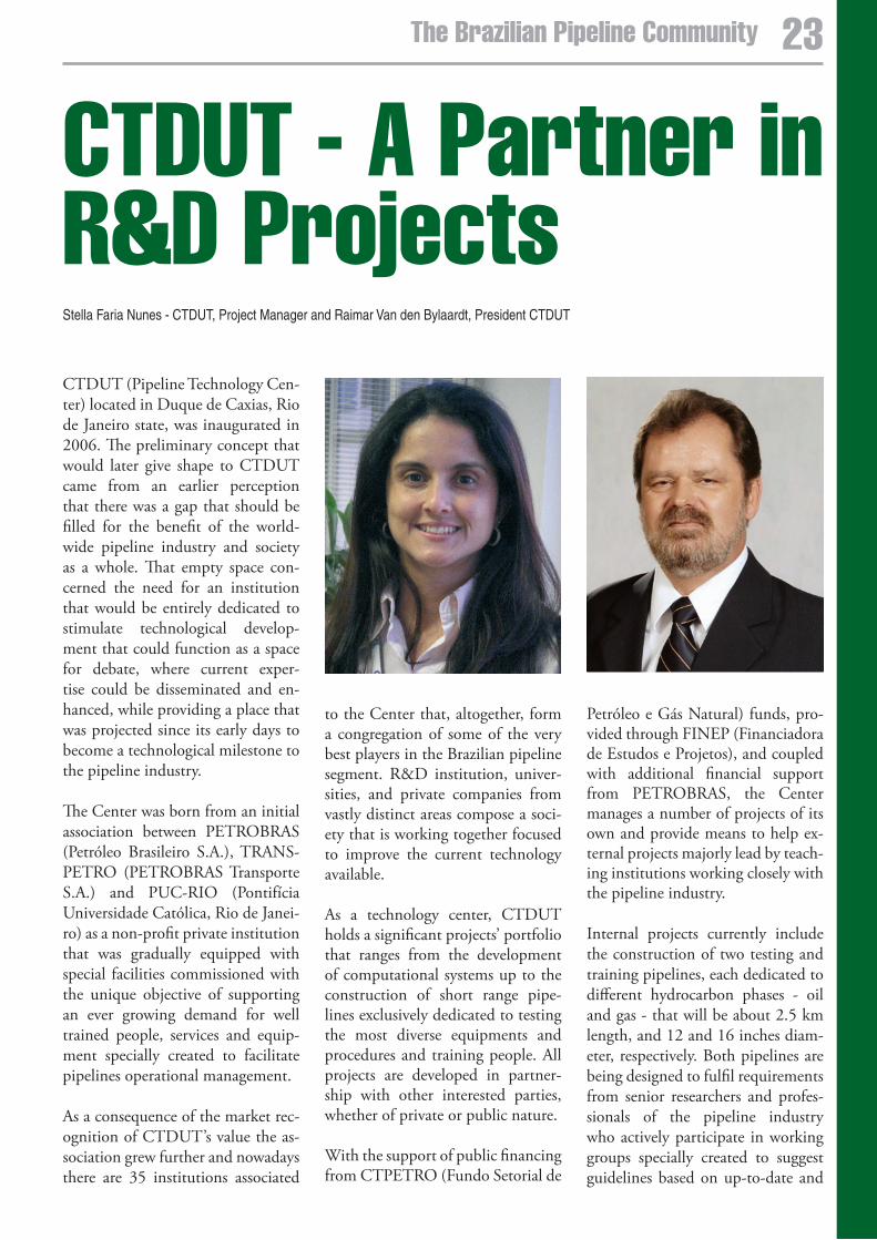
CTDUT - a Partner in R&D ProjectsStella Faria Nunes - CTDUT, Project Manager and Raimar Van den Bylaardt, President CTDUT
CTDUT (Pipeline Technology Cen-ter) located in Duque de Caxias, Rio de Janeiro state, was inaugurated in 2006. The preliminary concept that would later give shape to CTDUT came from an earlier perception that there was a gap that should be filled for the benefit of the world-wide pipeline industry and society as a whole. That empty space con-cerned the need for an institution that would be entirely dedicated to stimulate technological develop-ment that could function as a space for debate, where current exper-tise could be disseminated and en-hanced, while providing a place that was projected since its early days to become a technological milestone to the pipeline industry.
The Center was born from an initial association between PETROBRAS (Petróleo Brasileiro S.A.), TRANS-PETRO (PETROBRAS Transporte S.A.) and PUC-RIO (Pontifícia Universidade Católica, Rio de Janei-ro) as a non-profit private institution that was gradually equipped with special facilities commissioned with the unique objective of supporting an ever growing demand for well trained people, services and equip-ment specially created to facilitate pipelines operational management.
As a consequence of the market rec-ognition of CTDUT’s value the as-sociation grew further and nowadays there are 35 institutions associated
to the Center that, altogether, form a congregation of some of the very best players in the Brazilian pipeline segment. R&D institution, univer-sities, and private companies from vastly distinct areas compose a soci-ety that is working together focused to improve the current technology available.
As a technology center, CTDUT holds a significant projects’ portfolio that ranges from the development of computational systems up to the construction of short range pipe-lines exclusively dedicated to testing the most diverse equipments and procedures and training people. All projects are developed in partner-ship with other interested parties, whether of private or public nature.
With the support of public financing from CTPETRO (Fundo Setorial de
Petróleo e Gás Natural) funds, pro-vided through FINEP (Financiadora de Estudos e Projetos), and coupled with additional financial support from PETROBRAS, the Center manages a number of projects of its own and provide means to help ex-ternal projects majorly lead by teach-ing institutions working closely with the pipeline industry.
Internal projects currently include the construction of two testing and training pipelines, each dedicated to different hydrocarbon phases - oil and gas - that will be about 2.5 km length, and 12 and 16 inches diam-eter, respectively. Both pipelines are being designed to fulfil requirements from senior researchers and profes-sionals of the pipeline industry who actively participate in working groups specially created to suggest guidelines based on up-to-date and
23The Brazilian Pipeline Community
future needs and trends of the indus-try.
Among all external projects currently in CTDUT’s portfolio, seven deserve special mention. Some of the best Brazilian universities and research institutions like PUC-RIO, INT (Instituto Nacional de Tecnologia), UFRJ (Universidade Federal do Rio de Janeiro), UERJ (Universidade do Estado do Rio de Janeiro), UFF (Universidade Federal Fluminense), and IME (Intituto Militar de Engenharia) are in charge of developing research and achieving results of utmost relevance to the worldwide pipeline industry.
ERBF is the nickname given to the project coordinated by Professor Ar-thur Braga, from PUC-RIO in part-nership with INT, which is focused on the development of tools and field work methodology necessary to the installation of extensometers based on the BRAGG net in opti-cal fibre placed on the pipelines’ sur-face during its construction. At the same time, possible solutions for the
monitoring of cathodic protection deglutination from underground pipelines through the application of extensometry will be studied. Stud-ies for the definition of sensors’ den-sity that will optimize the relation between the system and the reliabil-ity achieved with the proposed tech-nique will also be developed with the objective of monitoring parameters like the soil (inclination and pres-sure), pipeline’s deformation due to internal pressure and flexion, and deformations caused by the cathodic deglutination and/or corrosion.
Professor Luís Fernando Alzuguir is the technical coordinator in charge of ARRASTE. The project will de-velop fundamental studies about the phenomena involved in pro-cesses that provide fluid flow attri-tion reduction. Such fundamental studies will constitute the basis for subsequent research at lab and pilot scales that will focus product flow in petroleum dedicated pipelines and heavy oils transport. All funda-mental studies will be performed at PUC-RIO’s Fluid Engineering Lab,
while pilot studies will take place at CTDUT’s oil testing pipeline. The research will investigate the effects of attrition reduction caused by the ad-dition of attrition reducent polymer, by the application of internal revet-ment, and surface modification at submillimetric and nanomillimetric scales, producing lubrication effects over the main fluid, with great po-tential of employment to heavy oils transport.
TRANSVAL, also under Professor Alzuguir responsibility, proposes the creation of an infrastructure to per-form tests and studies about valves employed in pipeline transportation. More specifically, the proposition is to build lab and field scale facilities that will allow the study of hydraulic transients when relief, blocking, and control valves are opened and closed. The lab scale facilities will be placed at PUC’s Fluids Engineering Labora-tory, while the real scale facilities will be constructed at CTDUT’s area. Both facilities will be able to answer an existing demand for valves’ test-
24 The Brazilian Pipeline Community CTDUT - R&D Projects
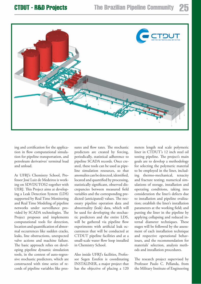
ing and certification for the applica-tion in flow computational simula-tion for pipeline transportation, and petroleum derivatives’ terminal load and unload.
At UFRJ’s Chemistry School, Pro-fessor José Luiz de Medeiros is work-ing on SDVDUTOS2 together with UERJ. This Project aims at develop-ing a Leak Detection System (LDS) supported by Real Time Monitoring and Real Time Modeling of pipeline networks under surveillance pro-vided by SCADA technologies. The Project proposes and implements computational tools for detection, location and quantification of abnor-mal occurrences like sudden cracks, leaks, line obstructions, unexpected valve actions and machine failure. The basic approach relies on devel-oping pipeline dynamic simulation tools, in the context of auto-regres-sive stochastic predictors, which are constructed with time series of re-cords of pipeline variables like pres-
sures and flow rates. The stochastic predictors are created by forcing, periodically, statistical adherence to pipeline SCADA records. Once cre-ated, these tools can be used as pipe-line simulation resources, so that anomalies can be detected, identified, located and quantified by processing, statistically significant, observed dis-crepancies between measured field variables and the corresponding pre-dicted (anticipated) values. The nec-essary pipeline operation data and abnormality (leak) data, which will be used for developing the stochas-tic predictors and the entire LDS, will be gathered via pipeline flow experiments with artificial leak oc-currences that will be conducted at CTDUT pipeline facilities and at a small-scale water flow loop installed in Chemistry School.
Also inside UFRJ’s facilities, Profes-sor Segen Estefen is coordinating INSTALINER, a major project that has the objective of placing a 120
meters length real scale polymeric liner in CTDUT’s 12 inch steel oil testing pipeline. The project’s main goals are to develop a methodology for selecting the polymeric material to be employed in the liner, includ-ing thermo-mechanical, tenacity and fracture testing; numerical sim-ulations of storage, installation and operating conditions, taking into consideration the liner’s defects due to installation and pipeline ovaliza-tion; establish the liner’s installation parameters at the working field; and putting the liner in the pipeline by applying collapsing and reduced in-ternal diameter techniques. These stages will be followed by the assess-ment of each installation technique and respective operational behav-iours, and the recommendation for materials’ selection, analysis meth-ods and installation procedures.
The research project supervised by Professor Paulo C. Pellanda, from the Military Institute of Engineering
25The Brazilian Pipeline CommunityCTDUT - R&D Projects
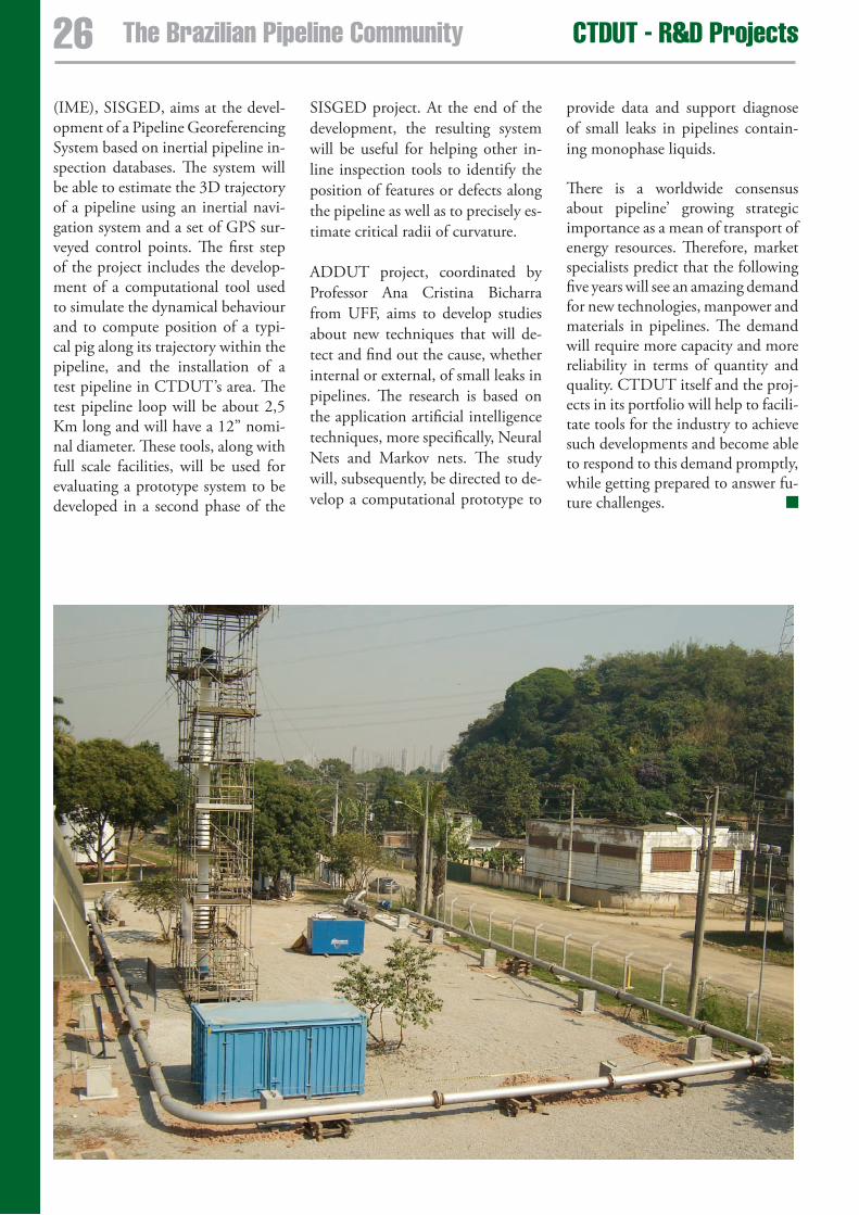
(IME), SISGED, aims at the devel-opment of a Pipeline Georeferencing System based on inertial pipeline in-spection databases. The system will be able to estimate the 3D trajectory of a pipeline using an inertial navi-gation system and a set of GPS sur-veyed control points. The first step of the project includes the develop-ment of a computational tool used to simulate the dynamical behaviour and to compute position of a typi-cal pig along its trajectory within the pipeline, and the installation of a test pipeline in CTDUT’s area. The test pipeline loop will be about 2,5 Km long and will have a 12” nomi-nal diameter. These tools, along with full scale facilities, will be used for evaluating a prototype system to be developed in a second phase of the
SISGED project. At the end of the development, the resulting system will be useful for helping other in-line inspection tools to identify the position of features or defects along the pipeline as well as to precisely es-timate critical radii of curvature.
ADDUT project, coordinated by Professor Ana Cristina Bicharra from UFF, aims to develop studies about new techniques that will de-tect and find out the cause, whether internal or external, of small leaks in pipelines. The research is based on the application artificial intelligence techniques, more specifically, Neural Nets and Markov nets. The study will, subsequently, be directed to de-velop a computational prototype to
provide data and support diagnose of small leaks in pipelines contain-ing monophase liquids.
There is a worldwide consensus about pipeline’ growing strategic importance as a mean of transport of energy resources. Therefore, market specialists predict that the following five years will see an amazing demand for new technologies, manpower and materials in pipelines. The demand will require more capacity and more reliability in terms of quantity and quality. CTDUT itself and the proj-ects in its portfolio will help to facili-tate tools for the industry to achieve such developments and become able to respond to this demand promptly, while getting prepared to answer fu-ture challenges.
2� The Brazilian Pipeline Community CTDUT - R&D Projects
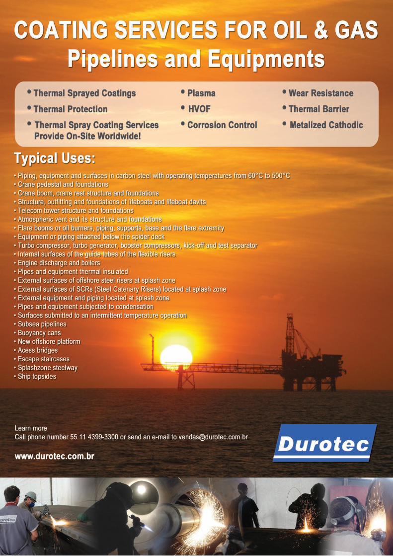
CTDUT – a shared solution for the Development of Pipeline Technology
Arthur J. F. Braga - CTDUT, Executive Manager and Sergio Damasceno Soares – Petrobras/CENPES, Engineer, MSC
The development of new technolo-gies for oil and gas pipelines usually faces a great difficulty in carrying out data survey and field testing, which are fundamental in the technologi-cal process. These pipelines are so committed to the activities of con-veyance and distribution of products that its operation must not suffer any interruption, being it intentional or even accidental, as a consequence of some test being undertaken. This as-pect is particularly critical in the dis-tribution of natural gas, as there is no possibility of storage in the con-sumption centers, and any paralyza-tion in the pipeline would mean an interruption in the distribution to the end consumer.
This obstacle results in the need for laboratory simulations and tests in pipeline segments of small length without product flow, characterizing actual oil and gas pipelines. The assessment of the functionality of PIGs (Pipeline Inspection Gauges) – which are fundamental inspection tools so as to ensure the integrity of the pipelines and to avoid accidents – is jeopardized and it is not satisfactorily solved with the widely employed resource of pulling the pig through a segment of the pipeline without any product, with the aid of a winch and a steel cable.
Not to mention the fact that carrying out a test battery through a 300Km
pipeline means to do the test today, wait for a truck to bring the pig back and then do it all again. Small details which could be the object of a quick assessment and correction, typical situations in the development of the software of the electronics attached to the pig turn out to be costly and time-consuming.
On the other hand, building and operating an actual pipeline, even if in a reduced length scale, represents an extremely high cost, something around tens of million dollars. Tak-ing into account the fact that the fre-quency of usage and undertaking of these tests is not high enough to jus-tify the progressive operation of this testing pipeline, its cost becomes disproportionally high.
The current solution of carrying out the tests in laboratories and in pipe-line segments without the product in order to ‘guess’ its validation in an actual pipeline afterwards is not ful-ly satisfactory and does not mirror the current status of environmental awareness and growing importance given to new technologies for the assessment of the integrity of pipe-lines.
Philosophy of the CTDUTThe CTDUT - Pipeline Technology Center - was created in order to remedy the deficiency in this model
of development and improve the competitiveness of the pipeline industry, with an innovative purpose in terms of Institution of Science and Technology (ICT).
Traditionally the ICTs count on a supporting institution, facing the well-known difficulties in keeping a research and development institu-tion effectively engaged in these ac-tivities and which would be, at the same time, capable of financing its activities with the funds resulting from its own work. These support-ing institutions can be companies which are interested in the tech-nology developed there, therefore determining a bias in the course of research under development, or gov-ernmental agencies which support, through direct or indirect subsidies, the activities of the ICT.
The CTDUT is a non-profit, pri-vate-owned company and was cre-
28 The Brazilian Pipeline Community
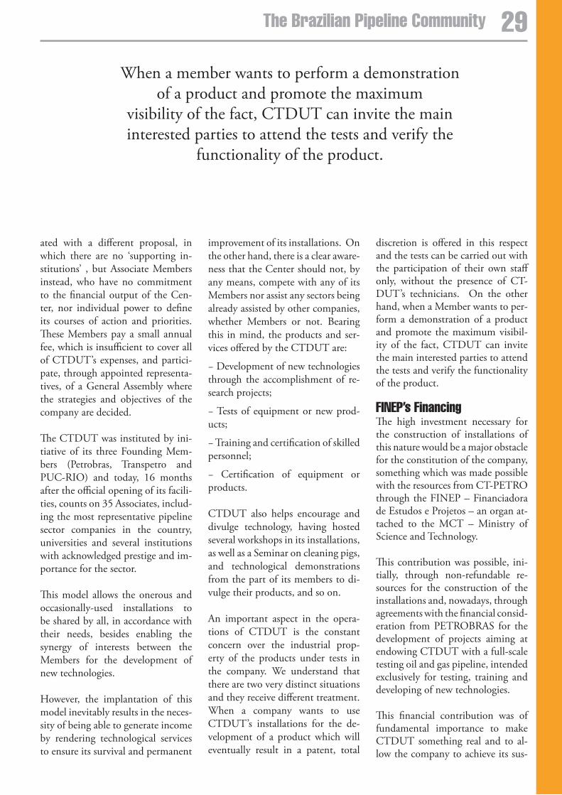
CTDUT – a shared solution for the Development of Pipeline Technology
ated with a different proposal, in which there are no ‘supporting in-stitutions’ , but Associate Members instead, who have no commitment to the financial output of the Cen-ter, nor individual power to define its courses of action and priorities. These Members pay a small annual fee, which is insufficient to cover all of CTDUT’s expenses, and partici-pate, through appointed representa-tives, of a General Assembly where the strategies and objectives of the company are decided.
The CTDUT was instituted by ini-tiative of its three Founding Mem-bers (Petrobras, Transpetro and PUC-RIO) and today, 16 months after the official opening of its facili-ties, counts on 35 Associates, includ-ing the most representative pipeline sector companies in the country, universities and several institutions with acknowledged prestige and im-portance for the sector.
This model allows the onerous and occasionally-used installations to be shared by all, in accordance with their needs, besides enabling the synergy of interests between the Members for the development of new technologies.
However, the implantation of this model inevitably results in the neces-sity of being able to generate income by rendering technological services to ensure its survival and permanent
improvement of its installations. On the other hand, there is a clear aware-ness that the Center should not, by any means, compete with any of its Members nor assist any sectors being already assisted by other companies, whether Members or not. Bearing this in mind, the products and ser-vices offered by the CTDUT are:
− Development of new technologies through the accomplishment of re-search projects;
− Tests of equipment or new prod-ucts;
− Training and certification of skilled personnel;
− Certification of equipment or products.
CTDUT also helps encourage and divulge technology, having hosted several workshops in its installations, as well as a Seminar on cleaning pigs, and technological demonstrations from the part of its members to di-vulge their products, and so on.
An important aspect in the opera-tions of CTDUT is the constant concern over the industrial prop-erty of the products under tests in the company. We understand that there are two very distinct situations and they receive different treatment. When a company wants to use CTDUT’s installations for the de-velopment of a product which will eventually result in a patent, total
discretion is offered in this respect and the tests can be carried out with the participation of their own staff only, without the presence of CT-DUT’s technicians. On the other hand, when a Member wants to per-form a demonstration of a product and promote the maximum visibil-ity of the fact, CTDUT can invite the main interested parties to attend the tests and verify the functionality of the product.
FINeP’s FinancingThe high investment necessary for the construction of installations of this nature would be a major obstacle for the constitution of the company, something which was made possible with the resources from CT-PETRO through the FINEP – Financiadora de Estudos e Projetos – an organ at-tached to the MCT – Ministry of Science and Technology.
This contribution was possible, ini-tially, through non-refundable re-sources for the construction of the installations and, nowadays, through agreements with the financial consid-eration from PETROBRAS for the development of projects aiming at endowing CTDUT with a full-scale testing oil and gas pipeline, intended exclusively for testing, training and developing of new technologies.
This financial contribution was of fundamental importance to make CTDUT something real and to al-low the company to achieve its sus-
When a member wants to perform a demonstration of a product and promote the maximum
visibility of the fact, CTDUT can invite the main interested parties to attend the tests and verify the
functionality of the product.
2�The Brazilian Pipeline Community
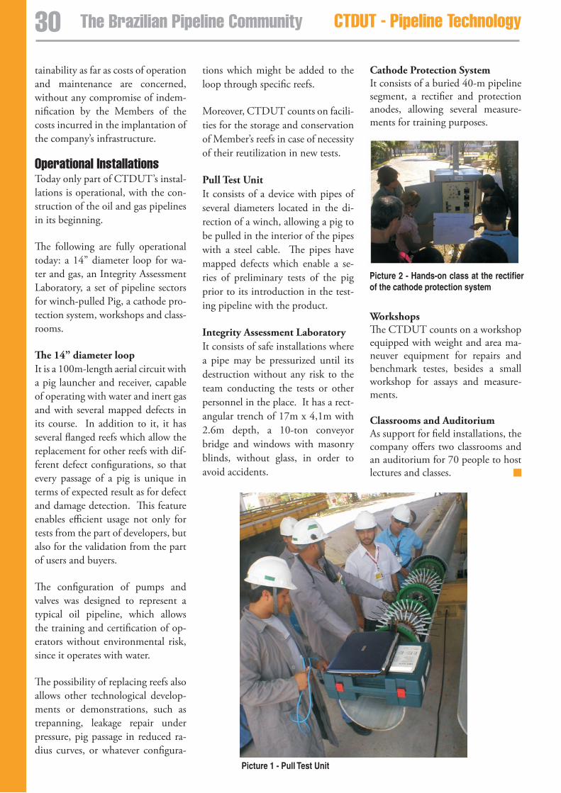
Picture 2 - Hands-on class at the rectifier of the cathode protection system
tainability as far as costs of operation and maintenance are concerned, without any compromise of indem-nification by the Members of the costs incurred in the implantation of the company’s infrastructure.
Operational InstallationsToday only part of CTDUT’s instal-lations is operational, with the con-struction of the oil and gas pipelines in its beginning.
The following are fully operational today: a 14” diameter loop for wa-ter and gas, an Integrity Assessment Laboratory, a set of pipeline sectors for winch-pulled Pig, a cathode pro-tection system, workshops and class-rooms.
The 14” diameter loopIt is a 100m-length aerial circuit with a pig launcher and receiver, capable of operating with water and inert gas and with several mapped defects in its course. In addition to it, it has several flanged reefs which allow the replacement for other reefs with dif-ferent defect configurations, so that every passage of a pig is unique in terms of expected result as for defect and damage detection. This feature enables efficient usage not only for tests from the part of developers, but also for the validation from the part of users and buyers.
The configuration of pumps and valves was designed to represent a typical oil pipeline, which allows the training and certification of op-erators without environmental risk, since it operates with water.
The possibility of replacing reefs also allows other technological develop-ments or demonstrations, such as trepanning, leakage repair under pressure, pig passage in reduced ra-dius curves, or whatever configura-
Picture 1 - Pull Test Unit
tions which might be added to the loop through specific reefs.
Moreover, CTDUT counts on facili-ties for the storage and conservation of Member’s reefs in case of necessity of their reutilization in new tests.
Pull Test UnitIt consists of a device with pipes of several diameters located in the di-rection of a winch, allowing a pig to be pulled in the interior of the pipes with a steel cable. The pipes have mapped defects which enable a se-ries of preliminary tests of the pig prior to its introduction in the test-ing pipeline with the product.
Integrity Assessment LaboratoryIt consists of safe installations where a pipe may be pressurized until its destruction without any risk to the team conducting the tests or other personnel in the place. It has a rect-angular trench of 17m x 4,1m with 2.6m depth, a 10-ton conveyor bridge and windows with masonry blinds, without glass, in order to avoid accidents.
Cathode Protection SystemIt consists of a buried 40-m pipeline segment, a rectifier and protection anodes, allowing several measure-ments for training purposes.
WorkshopsThe CTDUT counts on a workshop equipped with weight and area ma-neuver equipment for repairs and benchmark testes, besides a small workshop for assays and measure-ments.
Classrooms and AuditoriumAs support for field installations, the company offers two classrooms and an auditorium for 70 people to host lectures and classes.
30 The Brazilian Pipeline Community CTDUT - Pipeline Technology
31The Brazilian Pipeline Community
supporting academic developmentWith its Award for Pipeline Technology, Petrobras rewards new talent, and develops institutional marketing.
Within Brazil, Petrobras is the sin-gle largest investor in academic technological development. This takes the form of technology shar-ing agreements with several national universities and this interaction has benefited both parties. In return for agreements and financing academic works, universities and their research centers have helped contribute to numerous technology firsts that Petrobras has achieved over the last few years.
In pipeline transport technology, an area of great interest to Petrobras, it has partnered with the National Council for Scientific and Techno-logical Development CNPq. This cooperation led to the creation in 1998 of the Petrobras Pipeline Tech-nology Award. The objective of this prestigious award is fourfold. Firstly, to stimulate the development of new technology. Secondly, to raise the profile of pipeline technological ac-tivities within Brazilian universities. Thirdly, to identify teams with real ability to develop technology sharing agreements with Petrobras. Last but not least, to reward new talent and develop institutional marketing.
The Petrobras Pipeline Technol-ogy Award has two categories: stu-dents of national universities who develop technical works in the area of pipelines; and graduate students and those working for a doctor-ate. As many as three persons per category can be awarded the prize. The winners are given study scholar-ships for masters or doctorate thesis at national universities, and also the first two classified in each category receive cash prizes. In addition, the tutors of the two works in first place are given a grant for applying at the university.
In the five years of the award, a sub-stantial quantity of works have been presented, from 27 universities, in 11 states of the federation. In that time, 24 students have been offered scholarships, in addition to the total value of the awards of around (U.S.) $70,000, to 19 students and seven universities.
The interest of the academic segment in technological activities, related to transport by pipeline, has made pos-sible the realization of R&D projects
by universities in partnership with Petrobras, allowing new technology aimed at the pipeline transport sec-tor to be made available.
It is worth mentioning that various students, among the winners of the recent competitions, have already been admitted into Petrobras as engineers, which demonstrates the achievement of one of the hoped-for objectives, which is to direct new talent to the oil area and specifically towards the pipeline area.
The initial five-year period has been concluded. But because of the re-sults achieved to date, both in terms of the quantity and quality of the work presented and for the image of the company associated with projects of this nature, Petrobras decided to continue the award for a further year, which will make a total of six. At the same time, the creation of a new, broader project will be es-tablished. Known as the Petrobras Technology Award, this prize will cover the whole spectrum of E&P, and not just be restricted to the area of pipelines.
Wajid Rasheed
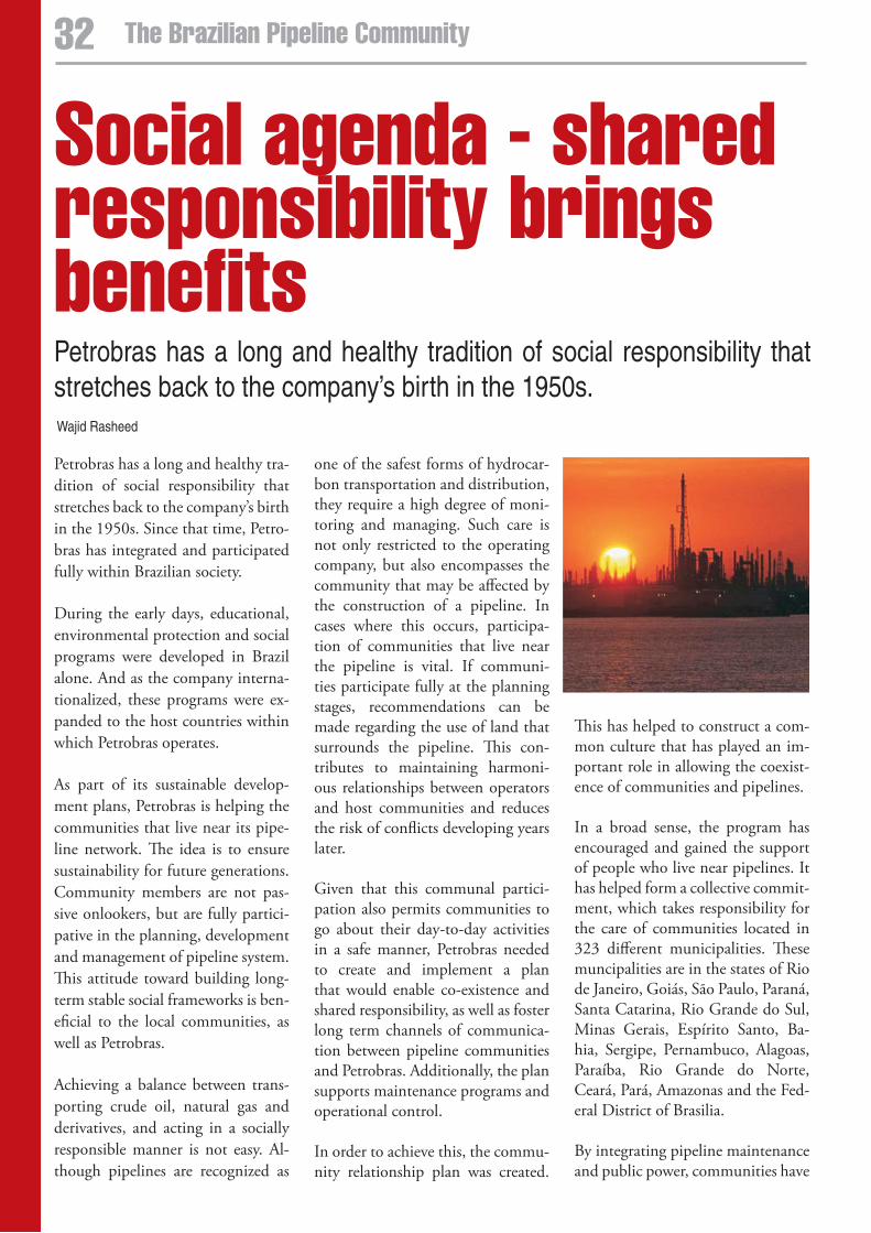
social agenda - shared responsibility brings benefitsPetrobras has a long and healthy tradition of social responsibility that stretches back to the company’s birth in the 1950s.
Petrobras has a long and healthy tra-dition of social responsibility that stretches back to the company’s birth in the 1950s. Since that time, Petro-bras has integrated and participated fully within Brazilian society.
During the early days, educational, environmental protection and social programs were developed in Brazil alone. And as the company interna-tionalized, these programs were ex-panded to the host countries within which Petrobras operates.
As part of its sustainable develop-ment plans, Petrobras is helping the communities that live near its pipe-line network. The idea is to ensure sustainability for future generations. Community members are not pas-sive onlookers, but are fully partici-pative in the planning, development and management of pipeline system. This attitude toward building long-term stable social frameworks is ben-eficial to the local communities, as well as Petrobras.
Achieving a balance between trans-porting crude oil, natural gas and derivatives, and acting in a socially responsible manner is not easy. Al-though pipelines are recognized as
one of the safest forms of hydrocar-bon transportation and distribution, they require a high degree of moni-toring and managing. Such care is not only restricted to the operating company, but also encompasses the community that may be affected by the construction of a pipeline. In cases where this occurs, participa-tion of communities that live near the pipeline is vital. If communi-ties participate fully at the planning stages, recommendations can be made regarding the use of land that surrounds the pipeline. This con-tributes to maintaining harmoni-ous relationships between operators and host communities and reduces the risk of conflicts developing years later.
Given that this communal partici-pation also permits communities to go about their day-to-day activities in a safe manner, Petrobras needed to create and implement a plan that would enable co-existence and shared responsibility, as well as foster long term channels of communica-tion between pipeline communities and Petrobras. Additionally, the plan supports maintenance programs and operational control.
In order to achieve this, the commu-nity relationship plan was created.
This has helped to construct a com-mon culture that has played an im-portant role in allowing the coexist-ence of communities and pipelines.
In a broad sense, the program has encouraged and gained the support of people who live near pipelines. It has helped form a collective commit-ment, which takes responsibility for the care of communities located in 323 different municipalities. These muncipalities are in the states of Rio de Janeiro, Goiás, São Paulo, Paraná, Santa Catarina, Rio Grande do Sul, Minas Gerais, Espírito Santo, Ba-hia, Sergipe, Pernambuco, Alagoas, Paraíba, Rio Grande do Norte, Ceará, Pará, Amazonas and the Fed-eral District of Brasilia.
By integrating pipeline maintenance and public power, communities have
32 The Brazilian Pipeline Community
Wajid Rasheed
Tubos Soldados Atlântico - TSA produces welded steel
pipes of the highest quality, with outside diameters
from 406 up to 1420mm, wall thickness from 5
up to 16mm and lengths of up to 18m, through the
helical submerged arc welding (HSAW) process.
TSA uses technology that meets all applicable cold or
hot bending process requirements, in full compliance
with both national and international standards.
Moreover, TSA relies on its high-technology
coating plant to apply three-layer polyethylene and
polypropylene, FBE and epoxy linings, capable of
coating the pipes both internally and externally.
Get to know some of our products:
PIPES FOR GENERAL CONVEYANCE
These can be applied in the sanitation, industrial
conduction, mining, irrigation and dredging segments.
PIPES FOR OIL & GAS PIPELINES
Manufactured according to API 5L for high
pressure gas pipelines, they offer high resistance
to internal pressure, as appropriate to the gas and
oil pipelines segment. They can be manufactured
in steel grades up to X-70 or higher, in accordance
with the strictest standards and specifications
required by this sector.
STRUCTURAL TUBES
These are an excellent alternative construction
element. Structural tubes are used for various
purposes such as pilings or supporting pillars,
and in various tubular constructions of general
application. A key differential of theses products
is their excellent straightening, which enables
pipes to produced in lengths of up to 32m.
Our best deal is the market’s trust in Our
quality, perfOrmance and services.
e s c r i t ó r i O s ã O p a u l Oav. paulista, 949 - 22º andar :: conj. 222belavista :: sãopaulo/sp :: cep: 01311-917tel . : (11) 3371 . 6129 / 3371 . 6135 fax: (11) 3284 . 5779 :: [email protected]
fábrica serra : : espíritO santO
pólo industrial piracema :: rodovia do contorno
br 101 - km 274 :: dist. de carapina :: serra/es
w w w . t s a . i n d . b r
found new voices and attitudes with which to shape safety procedures and environmental protection standards.
The program has also raised the pro-file of pipeline operations, benefits, risks, and laws regarding pipeline usage and the surrounding land among the Brazilian population. The wider population has also received information covering planned and preventative maintenance, safety and the protection of pipelines. By strengthening communication chan-nels between Petrobras and those that live in proximity to pipelines, the educational process has brought awareness to both sides.
Teaching has taken place within the host community through a “dialogue” process that questions, reflects and forms a new mentality regarding how the areas surrounding the pipeline can be used. The con-tent of these educational sessions are incorporated within procedures and safety policies to provide a record of environmental commitment and sustainable development.
To achieve this balance with the com-munity, local “teams” can call on dif-
ferent resources depending on specif-ic needs. For example, these can be community meetings, brain-storm-ing sessions, focus groups, meetings with leaders, publicity campaigns, school presentations, and tenant or freeholder associations.
The team uses materials that form part of the “community kit,” whose audiovisual resources are produced by Petrobras solely to be used in community activities. The kit is made up of posters, information folders, gifts, invitations, banners, and videos. After each meeting these items are tailored to fit within a fold-er that records each community’s ex-periences. This folder also serves as a narrative of that community.
Additionally, telephone numbers (including off hours and emergency numbers) help inform the commu-nity regarding basic technical facts about the pipeline, operational as-pects and safety measures. By mak-ing the host community conscious of and prepared to use these num-bers in the event of an emergency, the risk that any abnormal or sus-picious activities taking place near pipelines is also reduced.
The plan counts on the mobiliza-tion of community support and the inclusion of pipeline communities within Petrobras’ social program. To this end, educational messages are used to foster a culture of participa-tion, shared responsibility, safety and self help. This results in heightened awareness of pipeline technicalities among people dwelling near pipe-lines, as well as other opinion form-ers. Much has been clarified regard-ing the pipelines, the products they transport, and the safety measures in place.
By including host communities in pipeline planning, the needs and demands of communities in the ar-eas surrounding pipelines are better understood. This improves the over-all decision-making processes as all parties benefit from open communi-cation between local opinion form-ers. For example, the creation of a collective action group helps ensure the preservation of pipelines and ad-jacent land. The aim is to maintain a positive coexistence between the populace, host communities and the pipeline network.
By including host communities in pipeline planning, the needs and demands of communities in the areas surrounding
pipelines are better understood. This improves the overall decision-making processes as all parties benefit from open
communication between local opinion formers.
34 The Brazilian Pipeline Community social agenda

EPRasheed offers specialized services for the Oil and Gas Industry:• Marketing, Media Management,
Supplements and Advertising
• Technical Ghost Writing of company,SPE and industry articles
• Technical Translation of companybrochures, product information,technical data, instruction manualsand field applications
• In English, Portuguese, Arabic,Russian and Spanish
Trinidad48-50 Sackville St, Port of SpainTlf: + 1 868 730 6443
London11 Murray St, Camden, NW1 3RETlf + 44 17 53 57 22 57
BrazilAv. Prado Junior, 48 Sala 210 Copacabana Rio de Janeiro - Tlf: + 55 21 22 75 44 92
Supplements
Technical Translations
EngineeringMarketing Communications
Increase Sales
Brochures
Technical ArticlesSave Time
Communicate with Oil and Gas Companies
see us at: Rio Pipeline and sPe/aTCe