Embed Size (px)
Citation preview
The Boston Architectural Center TM321 Structures-II Section-A Fall 2005 Instructor Text Course Objective Grading Course Format and Outline Introduction (Chapter-1) Class #1 - September 6 Principles of Mechanics – Statics (Chapter-2) Class #2 - September 13 Introduction to Strength of materials: (Chapter-2) Class #3 – September 20 Introduction Structural Properties of Areas Class #4, October 27 Introduction Structural Loads-Model Building Codes in Design (Chapter-3), Class #5 - October 4 EXAM-1, Class #6, October 11 Review + Structural Properties of Areas-Stress Strain Class #7, October 18 (Material Continued) Materials And Their use in Structural Engineering Class #8, October 25 Members in Bending - Simple Beams (Chapter-6) Class #9, #10 (November 1, 8) EXAM-2 Class #11, Monday Nov. 15th Compression Members - Columns (Chapter-7) Class #12, 13, Nov 22, Nov 29 Review - Class #14, December 6 FINAL EXAM Class #15, December 13 Course book copy – Handouts Reading List Fall 2005 Schedule Recommended Reference Material
Pg 1-22
Boston Architectural Center TM321- Course Syllabus Fall 2005 Instructor: Garen B. Gregorian, PE, MSCE, MSME Phone: 617.484.3565 Fax: 617.484.3599 Email: [email protected] Text: Structures, Fifth Edition By Daniel Schodek Course Objective: Proceed from mathematical and physical principles to build an understating of forces and their effect on static stability and equilibrium of rigid bodies. Study of structural member’s capacity, based on the strength of the material and stiffness as it is related to its physical shape in length and cross section, and resistance to deformation. Application of general loading and code prescribed design criteria and concepts used in preliminary conceptual design and development of various structural systems used in building types. Application of principles of mechanics and strength of materials to analysis and design of basic structural components. Grading: Homework has been assigned as practice problems the completion of which should help in understanding the subject material. Homework assignments will not be collected, nor graded. You should read and perform the assigned homework prior to coming to class. Additional problems may arise in class and I may suggest, in addition, to work on a specific problem as well which may or may not be on the quiz the following week. I will try to answer any questions you may have on the subject. Weekly Quizzes will count as 30% of total grade. 20 minute will be devoted to quizzes. Exam-1: 20% Exam-2: 20% Final Exam: 30% Exams should take 1.5 to 2 hrs. However more time may be given up to the end of the period depending on the rate at which you all finish the exam. Note: Quizzes will be returned the following week. Quizzes not handed in or if I forget to collect them, will count as a grade of zero. Exams will be closed book open notes.
Pg. 2 of 22
Boston Architectural Center TM321- Course Syllabus Fall 2005 Course Format and Outline All reading material listed in the syllabus should be read prior to class. In class we will review any questions you have on the reading assignments and proceed to solve problems on the blackboard. This course will be taught by example. I will solve problems similar to the lecture notes and exams provided from previous years but with different variables to make it interesting. Your attention will be required during class to help arrive toward the completed solution. I will also incorporate various problems from our office practice for your review and information. Calculators, the text book, and the relevant handout should be with you in class. Introduction (Chapter-1) Class #1 - September 6 Structural Engineering – and general quick review of what to expect from the course. Plus an overview and discussion of what a problems structural engineers are faced with during their daily practice. Handout - Lecture Notes from years previous. Read prior to first class. Principles of Mechanics – Statics (Chapter-2) Class #2 - September 13
Hand out - Notes from years previous of what I cover in class. Force as a vector with magnitude and direction Components of forces Concurrent Forces, Collinear Forces, Moment, Couple, Torque Equilibrium of rigid bodies Simple beams, cables, arches, simple roof framing in residential construction. Static Stability, and propped cantilever beam, retaining wall, as examples.
Introduction to Strength of materials: (Chapter-2) Class #3, #4 – September 20, 27 Introduction to Stress and Strain, and mechanics of deformable bodies:
Terminology: Stress: Force/Area [F/L.L] [kips/square inch] F=Force (Lbs, or Kips L=Length (inches or feet for SI units) A= square inches, or square feet Strain: Change in length over original length of the member under tensile or compressive load. Factor of safety: Stress at Yield Plastic or Ultimate/ Factor enabling the quantity to be used in design. (Factor dependant on uncertainty in determination of loading, testing of material)
Pg. 3 of 22
Boston Architectural Center TM321- Course Syllabus Fall 2005
Allowable Stress a quantity and value determined to be used in design of members given the allowable loads. Factor of Safety for steel in compression = 2/3 x Yield stress. Load Factors: Factors to increase loads stated in building codes based on uncertainty in method of quantifying loads. (For example, 1.4 Dead, 1.7 Live, 0.7 EQ., 1.0 Wind) Ultimate Stress (determined while testing) The highest point in stress strain curve before fracture. Ultimate Strength (determined by applying a factor of safety depends on the loading condition and type of member being loaded and importance of the member in structural stability, axial load on column, bending moment or shear in beam) Elastic Limit=Proportional Limit: point on the stress strain curve up to which if load is removed the material will return back to its original length and shape Elastic Range: Range on the elastic curve up to the elastic or proportional limit. Yield Point: the point on the stress strain curve after which the specimen/material will not return to its original length and shape. (After yield, the crystal structure of the specimen/material begins to change and rearrange for resistance up to ultimate stress) Plastic-Strain hardening Range: Range between Yield and Ultimate Stress. Plastic limit: In the plastic range, The specimen will be able to take additional load. 1.2 times the yield strength. Ultimate stress: Maximum stress the specimen can be subjected to under testing. The point on the stress strain diagram after which the material elongates without further additional load and elongates until fracture. Highest point on stress strain curve. Toughness: Measure of how much force is required to deform the material to breaking point. The area under the stress strain diagram. Analogy: work = force x distance from physics. Charpy impact test (impact with drop hammer) used to determine toughness for ductile materials. Hardness: Resistance of the material to penetration. Resilience: The ability of the material to absorb energy Fatigue: Materials response and failure in form of fracture under constant repeated loading. S-N Curve for fatigue - Stress vs. Number of Cycles of applied load. ( Example-Airplane wing and how long can it sustain dynamic stresses induced by vibration of the wing during flight before failure) Analogy, Foundation Design and Geotechnical Engineering:
Preliminary sizing of rectangular concrete footing.
Geotechnical investigation and penetration test, blow count, to obtain bearing capacity of Soils, and allowable stress. Foundation Types for Buildings, shallow footings, deep footings, foundation walls, soil retaining structures, lateral earth pressure. Determining preliminary footing size for buildings for Conceptual design phase or quick checks. Brief Introduction to bending moment and shear in beams. Study of beams as most commonly encountered structural element which spans horizontally from support to support carrying vertical gravity loads. Bending Moment Diagrams: Bending of beams as a graphic representation of in plane rotational effect of gravity loads on horizontally spanning structural elements. Shear Diagrams: Shear represented as magnitude of vertical load across the beam span and as a sliding effect of vertical and horizontal planes of the member cross section.
Pg. 4 of 22
Boston Architectural Center TM321- Course Syllabus Fall 2005
(Note: in Chapter 6, we will study how the member can be shaped to better resist these rotational and sliding tendencies.)
Introduction Structural Properties of Areas Class #4, September 27
Continue with bending moment and shear diagrams Center of gravity of a solid, determining a point within a solid where it can be balanced. Centroid of an area determining the point in a flat body (an area) where the body can be balanced. Centroid as the location of the neutral axis of a beam. Moment of inertia
Introduction Structural Loads-Model Building Codes in Design (Chapter-3), Class #5 - October 4
(By this time we have had a chance to solve problems in class where we have used most of the concepts of chapter 3 for analysis of some building components. This lecture will cover mostly dynamic loads due to wind and earthquake and code prescribed procedures for obtaining loads used in design. Material should be useful in preparation for ARE exam.)
See lecture on lateral loads online for exposure to subject.
Modeling and approximation of loads used in structural design. Static Loads: Live loads, Dead Loads Dynamic Loads: Wind, Earthquake, and Dynamic Live loads Design for Strength, Serviceability General Concepts used in Design. Application of Principles in Design of Buildings and Building Components
EXAM-1, Class #6, October 11 Review + Structural Properties of Areas-Stress Strain Class #7, October 18 (Material Continued)
Center of gravity of a solid, determining a point within a solid where it can be balanced. Centroid of an area determining the point in a flat body (an area) where the body can be balanced. Centroid as the location of the neutral axis of a beam. Moment of inertia of an area, as the sum of the second moment of areas about an axis of rotation. Axis of rotation will be taken as passing through the Centroid of the Area. Moment of inertia should be thought of as an out of plane rotation of an area about an axis. (Centroid or otherwise)
Pg. 5 of 22
Boston Architectural Center TM321- Course Syllabus Fall 2005
Parallel axis theorem. For finding moment of inertia about any axis. Moment of inertia as a cross section resistance to bending and rotation. Polar moment of Inertia as it is related to Torsion and Twist (In plane rotation of a circular) disc. The shape of the cross sectional area on how it will resist vertical shear. Practical implications of area composition for load resistance. Radius of Gyration (Moment of Inertia and Area) if an object was rotated around an axis and during rotation its mass became concentrated equally on each side of that axis at a distance r, this r would be the radius of gyration of the object or the rigid body. Study of the radius of gyration as related to buckling of columns.
Materials And Their use in Structural Engineering Class #8, October 25
Read course book copy. Responsible for definitions and material in notes which are covered in class.
Metals: Structure of metals and Alloys: Metals, Crystal Structure of Metals, Cooling-phase diagrams and Manufacture of Metals. Taking advantage of properties of various metals to create materials for specific use. Changing Structural, Electrical, Magnetic properties.
Properties and Uses of Ferrous Metals, The Manufacture of Iron and Steel.
Steel, Iron, Aluminum and various alloys hand out Mechanical properties of metals Handout on mechanical properties. Wood: Wood as a structural material: Old Growth wood, New Growth wood Species of wood as factors determining the strength of wood specimen. Wood as an orthotropic material. Brick – Concrete Units – Reinforced Concrete: Brick clay, fired in oven bonded with mortar strength usually up to 5000 psi. Concrete brick units the strength of concrete brick masonry about the same as that of concrete depending on the mix. Types of Brick and CMU, M-S-N. Mortar: Type M S N O (derived from the word MASONRY) M being the strongest and O being the weakest. Reinforced Concrete Concrete a mixture of Cement, Water, and Aggregate. Admixtures, structural properties of concrete
Pg. 6 of 22
Boston Architectural Center TM321- Course Syllabus Fall 2005
Construction issues, testing, and quality control Members in Bending - Simple Beams (Chapter-6) Class #9, #10 (October, 1, November, 8)
Review Stress Strain Diagram Analysis and determination of moment and shear resisting capacity of beams. Effect of shape of cross section and material of the structural element on its moment and vertical and torsional shear resisting capabilities. Preliminary Design of Wood Beams Text and – Handout – Steel Beams and Framing Elements (Chapter 5) Simplified Engineering for Architects and Builders. Some practical connection design and detailing will be covered. Preliminary Design of Steel Beams Allowable Stress Method – Handout – (Chapter 9) Simplified Engineering for Architects and Builders. Preliminary selection of open web steel joists. Some practical connection design and detailing will be covered. Preliminary Design of Concrete Beams Alternate Design Method (Stress Method) – Handout (Chapter 13) Simplified Engineering for Architects and Builders.
EXAM-2 Class #11, Tuesday Nov. 15th Members in Compression - Columns (Chapter-7) Class #12, #13
Compression members - Columns. Euler column buckling formula, for a column, of given cross sectional shape and length, the buckling load will be related to its Modulus of Elasticity and inversely to the square of its unbraced length. Critical load as the load at which the column will fail by crushing or buckling failure. Failure defined by testing for the intended use of the column. Short columns, crush Intermediate Columns buckle but are most efficient and Long Columns buckle with much less load Unbraced length End conditions Moment of Inertia, area, radius of gyration, ie; distribution of material about buckling axis as a variable affecting the column buckling load. Column Buckling Phenomena, and crystal structure of the material as it relates to direction of column buckling of a circular cross section. The direction of rotation of the cross sectional area about the buckling axis will depend on how the column was manufactured. For a purely formed
Pg. 7 of 22
Boston Architectural Center TM321- Course Syllabus Fall 2005
column of circular cross section we can not determine what direction (about which axis) the column will buckle. Design of Compression Members Simplified Design of Wood Columns Simplified Design of Steel Columns Simplified Design of Reinforced Concrete Columns
Review - Class #14, December 6
FINAL EXAM Class #15, December 13
Pg. 8 of 22
Boston Architectural Center TM321- Course Book Handout Fall 2005 Course book copy – Handouts Reading List: In addition to your text book I have included the following hand outs for your reference. Please note that I will try to cover as much of the hand outs in class as possible and that you will be responsible for the subject matter covered. Therefore it will be to your advantage if you have the hand outs with you in class. Though you are not expected to be thoroughly familiar with the subject matter for the course, I will try to answer any questions you may have during a discussion period if it does not interrupt the lecture for the day. Pocket Guide to Structural Formulae and Diagrams (Course Book): (class #1) Non-Users Pocket Guide to transient Knowledge Necessary for Structural Divisions of the Architect Registration Exam – ARE, David J. Thadeus, AIA, 2004 Structural Properties of Areas (Course Book): (class #6, #7) Chapter 3, Elementary structures for Architects and Builders, 17 pages including cover. Provided for reference and general information. Not covered in lecture. Material properties (Course Book): (Class #8) Ferrous and Non Ferrous Metals in Engineering: Engineering Materials and Processes, WM. Howard Clapp and Donald Sherman Clark, The International Textbook Company, 1938. Chapter 2: Read pages 47 to 57. (27 Pages total)
Structure of Metals and Alloys: Crystal structure of metals mostly used in engineering Cubic, Tetragonal, Hexagonal Arrangement of crystals Etching and view under microscope The stronger metal protects the more noble metal based on crystal structure Effect of Stress on Deformation of crystal and modulus of Elasticity
Ductility and Failure of brittle material vs. Ductile material-Cone develops in ductile material vs. brittle material fails by pure shear at 45 degree to the plane of applied stress Effect of cooling on formation of metal alloy
Chapter 3: Engineering Materials and Processes, One form by Heating materials, mixing and cooling.
Crystallization, Cooling Curves, and consistency. Read pg. 70-87. (10 Pages total) Taking advantage of physical (mechanical, electrical, magnetic, etc.) properties of metals to create a homogeneous material (cooled mixture), the properties of which will suit the intended use.
Phase Diagram:
Pg. 9 of 22
Boston Architectural Center TM321- Course Book Handout Fall 2005
Graphical representation of a state of the mix of materials at a given time as the mix is cooled. Single phase diagram – Water and salt (ice and salt solid solution) Eutectic- The minimum temperature at which the mixture freezes or forms a solid. Double phase diagram – As for Steel and Carbon two phases of solid formation and various mix solution at each phase for a given Temperature and % of each material in the mix.
Chapter 4: Properties and Uses of Ferrous Metals, The Manufacture of Iron and Steel. Read for reference 1st page covered in quiz. Chapter 5: Metallurgy, Properties and Uses of Ferrous Metals and Alloys-II Aluminum, Magnesium, Copper, Nickel(For Reference only 8 Pages) Chapter 7: Metallurgy, Properties, and Uses of Non-Ferrous Metals and Alloys
Copper, Zinc, Tin, Aluminum, Lead, and Alloys. (14 pgs total) Concrete: Concrete Craftsman Series, Cast in Place Walls, Second edition, ACI, June 200. (Total 29 pages) Read for more detail (for reference) - Concrete Construction Engineering Handbook, Dr. Edward G. Nawy, CRC Press, New York, 1997 pgs 5-1 to 43. (Total 44 Pages + Cover) Wood: Engineering materials and their Applications, Second Edition, Flin/Trojan, Houghton Mifflin, 1980. pg.465-472. Design of Beams: Wood Spanning Elements Chapter 5, Simplified Engineering for Architects and Builders. (10 pages including cover) Steel Beams and Framing Elements, Chapter 9, Simplified Engineering for Architects and Builders (16 pages including cover) Reinforced concrete design, Chapter 13, Simplified Engineering for Architects and Builders. (18 pages including cover) + 5 pages Simplified Design of Concrete Structures 5th Edition, James Ambrose, JWS, 1991. Compression Members: Introduction to (preliminary design of) Wood Steel and Concrete column design. Wood Column: Handouts will clarify formulas in textbook and show the historical development of wood column formulas from 1917 to the current practice.
Pg. 10 of 22
Boston Architectural Center TM321- Course Book Handout Fall 2005 1. American Institute of Timber Construction, Timber Construction Manual Third Edition, 1985 Pages
5-108 to 5-117. Column formulas which are used in text book, includes graph which can be used to calculate the column allowable load.
2. Structural design in wood, 2nd Edition, Judith J. Stalnaker, Ernest C. Harris, Chapman and Hall. Pages 131 to 135. Introduces the history of column design and has the latest design formulas for wood columns.
3. Simplified engineering for architects and builders, Ninth Edition, James Ambrose, John Wiley & Sons, Inc. Pages 212 to 219 for reference, example and additional information.
4. Also: Pages 180 to 183 listing the mechanical properties of structural lumber as listed in National Design Standards.
Pg. 11 of 22
The Boston Architectural Center TM321 Recommended Reference Material: Recommended Reference Material: 1. Elementary Structures for Architects and Builders., 4th Edition, R.E. Shaeffer, Prentice Hall, 2002. 2. Shaping Structures, Waclaw Zaelewski and Edward Allen, John Wiley and Sons, Inc.1998. Great
explanation of the graphical method for determining forces in structures and forming structural shapes.
3. Introduction to Mechanics of Solids, Stephen H. Crandall and Norman C. Dahl, Mc Graw Hill Series
in Engineering Sciences 1959. 4. Introduction to Mechanics, Matter and Waves, Uno Ingard and William L. Kraushaar, Addison
Wesley, Publishing Co., Inc. 1960. Great review of physics. 5. Mechanics, Statics and Kinetics, Vol.1, Charles E. Fuller and William A. Johnston, John Wiley, 1913 6. Strength of Materials, Fuller and Johnston, Vol. 2. 7. Design of Building Trusses, James Ambrose, John Wiley and Sons, 1994. Great graphical solutions
for forces in truss members. 8. Elements of Strength of Materials, Fifth Edition. Stephen P. Timoshenko and D. H. Young.Van
Nostrand Company. A good reference with interesting problems in strength of materials, simplified brief yet clear discussion of concepts.
9. Mechanics of Materials, Beer and Johnston, McGraw Hill, 1981. Great book, elementary concepts are
well explained, from the stand point of mechanical engineering. 10. Mechanics of Materials, Second Edition, E. P. Popov, Prentice hall, inc., 1976. 11. Photoelasticity, Principles and Methods, by H.T. Jessop and F. C. Harris, Dover Publications, NY,
1950. with 164 photographs and diagrams, a great visual representation of stress and strain in an elastic solid.
12. Theory of Elasticity, Engineering Societies Monographs, Third Edition, Timoshenko and Goodier,
MC Graw Hill, 1970. Advanced mathematics and differential calculus may be required for understanding of the solutions yet the explanation is helpful for general grasp of the mathematical models which are used to arrive at the solutions. Reading Articles on Torsion and Cantilever beam with a concentrated load is strongly recommended.
13. A Textbook on Crystal Physics, W. A. Wooster, M.A., PHD, Cambridge at the University Press,
1938. 14. What I would consider a gem. Theory is well explained and great graphic representation as well. An
Instant Classic in my library. 15. Physical Properties of Crystals, their Representation By tensors and Matrices. J. F. Nye, M.A., PHD,
Oxford At The Clarendon Press corrected sheets of the first edition, 1960.
Pg 12-22
Boston Architectural Center TM321- Course Book Handout Fall 2005 16. Theory of elasticity of an Anisotropic Body, S. G. Lekhnitskii, Mir publishers, Moscow, 1981.
(Translated from Revised 1977 Russian Edition.) 17. Structural Stability, Theory and implementation, W.F. Chen and E. M. Lui. Advanced mathematics
and differential calculus may be required for understanding of the solutions for column stability. Yet again the explanation is helpful for general grasp of the mathematical models which are used to arrive at the solutions. Reading chapter 2 on columns is recommended for more detailed explanation.
18. Also on Structural Stability, Theory of Structural Stability by Timoshenko and Gere, Second Edition,
McGraw Hill Classical Textbook Reissue. Chapter 2 on Elastic Buckling of Bars and Frames is recommended. Also Article 2.17 on The effect of Shearing Force on critical Load, and Buckling of Built up columns should be of interest. (The mathematical equations may be a bit intimidating! Read the explanation for the derived results)
19. Concrete Construction Engineering Handbook, Edward G. Nawy, CRC Press, 1997. 20. Concrete Craftsman Series, Second Edition, ACI, June 2000. 21. Design and control of concrete mixtures, Thirteenth edition, Portland Cement Association, 1994. 22. Steel Design Handbook, LRFD Method, Akbar R. Tamboli, McGraw Hill, 1997. 23. Manual of Steel Construction, Allowable Stress Design, Ninth Edition, AISC, 1989. 24. Simplified design of Steel Structures, James Ambrose, John Wiley, 1976. 25. Simplified design of Concrete Structures, James Ambrose, John Wiley, 1991. 26. Reinforced Concrete Design, Third Edition, Chu Kia Wang, Charles G. Salmon, Harper & Row, 1997. 27. Reinforced Concrete Design, Kenneth Leet, McGraw Hill, 1982.
Pg. 13 of 22
The Boston Architectural Center TM321 Recommended Reference Material: Introduction to Materials and Material Science: Creating metals from raw materials and combining (mixing) metals to form one with the desired property. Creating metals from raw materials: Mined ore from the queries, brought to the refinery, Separated using heat. And put back together in the furnace to make ingots or continuously create. (Some furnaces operate continuously when turned!) Blooms for shapes, Billet for rods ad wires Slabs for plates Alloys: One form Alloys created is by heating and addition of different metals in the furnace, and heating and cooling once more in the mills.
Metals + Metals solid solution or compound Alloys: Relative % of Metals + Metalloids solid solution or compound
Metals + Non metals solid solution or compound Cooling diagrams single phase mix. Water + Salt (Na-Cl) Trying to obtain a solution of both Solid crystals of Ice and Salt Take pure water and cool it till freezing. At its freezing point 32 deg. F. Add salt to water and cool mixture As we add salt to the solution the mixture starts to solidify (freeze) at lower temperature and it takes more time for the solution to form a solid. (ie; the rate at which the solution solid formation with respect to time T) 1. Lower rate of cooling Adding Salt will 2. Lower temperature for solid formation At some point, no matter how much salt we add the mixture will not solidify perfectly lower than T. This point and time is called the Eutectic of the mix. “of low melting point”. (with constant heat of cooling) The phase diagram is then the plot of the mix where % of mix is varied as the mix is cooled. Given % of elements in the mix Determine % solid A and % B, in mix for each temperature Take Eutectic point, Draw vertical line EU line to left is %A to right %B Pick a temperature T Draw horizontal line Pick a % of solution on horizontal axes
Pg 14-22
Boston Architectural Center TM321- Course Book Handout Fall 2005 Determine % of each mix below the eutectic Above the eutectic, Use lever law to determine % of each mix in given form for any temperature by moving up T axis. Two phase alloys Steel Show graph. For Iron Carbide Diagram Three phase alloys 3 metals or nonmetals forming a solution. Diagram is triangular in form. (Analogy- Making Soup and Cooking in general. Healthy, Energetic, Fatty, Acidic - Taste, Color, Texture and Consistency.) Concrete:
• Cement + Water+ Aggregates (Sand and Gravel) Water: Drinkable Cement: Limestone + Clay + Iron Oxide
(+Gypsum added to control early hydration)
• Portland cement is Hydraulic Cement: Sets and Hardens due to chemical reaction with water.
Types of Portland Cement: Type-I : Normal cement – All purpose, used in slabs, concrete buildings, bridges. Type-II: Moderate sulfate resistance – Used in Coastal or Marine areas. Strength gain in 56
days. Type-III: High early strength cement –Early strength gain. Type VI: Low heat of hydration – Slower strength gain Type V: High sulfate resistance
• Blended Cements ASTM C595 • Masonry Cements ASTM C91 for Mortar in masonry construction.
Aggregates: Sand (Fine) : size < 3/8” Gravel (Coarse) : 3/8”< size < 1-1/2” Admixtures:
• Air Entraining Admixture: Freeze thaw resistance by keeping air
Pg. 15 of 22
Boston Architectural Center TM321- Course Book Handout Fall 2005
bubbles in concrete from breaking up. • Accelerating Admixture: Speed up setting time increases strength
used for cold weather • Retarders: Slow down setting time used for hot
weather • Water Reducers (WRA): Reduce amount of water/cubic yard of
concrete for a given slump by 5 to 10%. Reduces friction between particles in form of electric reaction much like air entraining admixtures and increases flowability.
• High Range Water Reducers: Superplasticizer increase strength Flowability, workability Used in high strength concrete. Though mix may appear to have more water the water is removed from the mix during chemical reaction.
Water to Cement Ratio: Ratio of weight of water to weight of cement
Typically 0.5 good range 0.4 to 0.6 Slump: Measure of workability of concrete 3 to 5 inches With admixtures WRA can reach up to 7 inches Slump test/cone test: concrete poured in a cone. Cone is inverted and lifted. Final height of concrete after cone is removed is recorded. Weight: Normal weight concrete: 145 lbs/cu ft. Weight /inch of thickness: 145 x 1/12 = 12 lbs/sq ft (per inch of thickness) Light weight concrete: 110 lbs/cu. ft. Note: Water 62.4 lbs/cu ft. about ½ of cement with water/cement ratio of .5
½ of mix is Water ½ is Cement As a total the materials have the following ratio: Concrete 1-2-3 ratio 0.15 water 0.3 cement 0.6 aggregate Mortar 1-1-6 ratio %75 1 Cement 1 Lime (1+1)*3=6 part Sand (Consistency - Water retainage measured by testing, cone penetration method) Similar to mortar and grout as the ratio of water for mortar and grout is less than that of concrete, the mortar mix is more sticky and provides a stronger bond. Grout has a bit more water as the aggregates are larger and concrete has the most water in all of the mixes discusses. As flowability is a problem in concrete, the water reducing admixtures are used to increase flowability by increasing slump, increase strength, and for ease of placement and reduce cost. Compressive Strength:
• Concrete Compressive Strength: typical 3000 psi to 4000 psi • Allowable Compressive Stress = 1000 psi, Tensile Stress 100 psi. (not allowed!)
Initial Set – 1 to 5 hrs. to reach 500 psi. Final Set - Hydration and strength gain in 1 Month typically (28 Days) 1/2 strength gain is in 7 days for water to cement ratio of .5 (see page 72 handout)
Pg. 16 of 22
Boston Architectural Center TM321- Course Book Handout Fall 2005
• Compressive strength test: Break 6” diameter cylinders and record the stress. Test at 7 days and 28 days. Retest failed concrete at 56 days.
• Mixed at the plant, or mixed at the site, site mix not allowed by most project specifications. • Mix Design. The manufacturing plant-supplier should have the design mix prepared. The
contractor must show the mix has been used for at least 3 projects successfully. Try to obtain this document from the contractor.
• If this can not be determined, testing of the mix should be performed prior to construction. • During construction tests should be performed as well. • Number of tests required: For 50 cubic yard One test, and one for each 25 cubic yards. Number of
test specimens should be at least 5 to enable to get at least 3 readings and 2 for safety, may break during travel and handling.
Concrete sets in about 7 hours maximum and gains most of its strength in half that amount of time. Its strength keeps increasing while curing under optimum conditions and in 28 days. Interior concrete elements remains moist even during services life of the structure sometimes for up to 5 years. Curing and moisture problems in concrete depends on the expansion joint, construction joints and amount of reinforcing used in the slab. The steel reinforcing will reduce the cracks. Vapor barriers can also be a problem since they will not let the moisture leave the concrete. The concrete structure needs to breathe and dry. Installation of a cushion of sand of 2” or more will absorb the moisture below the slab. The sand cushion will also help minimize the tearing of the vapor barrier during construction. Concrete which is placed on ground without vapor barrier in an out door environment will rarely crack. Concrete surface should be covered with wet burlap and be kept continuously moist. Sprinkling water on the surface should be avoided as it will harm the surface sand aggregates which have not had chance to get submerged during construction. Removal of forms: Forms can be removed after 7 days for structural elements which are not vertical load bearing. Cracking of concrete: Concrete structural elements in general are assumed to have cracked so the neutral axis of the member varies depending on the amount of reinforcing in the beam and shape and cross section of the beam. Shrinkage and Expansion Cracks in slabs on grade Further reference see VA Master Spec online. Brick – Concrete Masonry Units (CMU):
Brick clay, fired in oven bonded with mortar strength usually up to 5000 psi. Used to be sun dried which would result in much stronger brick. Types of brick and strength is dependant on the curing of the brick in the oven.
Pg. 17 of 22
Boston Architectural Center TM321- Course Book Handout Fall 2005
For exterior brick the surface of the brick has to be strong enough to prevent water penetration. Once the exterior of the brick is chipped away, the softer interior can be viewed. For structural brick, the whole unit must be cured completely. Concrete brick units the strength of concrete brick masonry about the same as that of concrete depending on the mix. Mortar: Type M S N O (derived from the word MASONRY) M being the strongest and O being the weakest. Mortar is a fine graded mixture of sand and cement and water. (Similar to concrete but with smaller particles like sand and water added as needed for consistency and workability) Cement Mix of Portland Cement+ Hydrated Lime+Sand
Or Masonry Cement+Hydrated Lime+Sand Either way total volumetric ratio of Cement+Lime should not exceed 3xSand. Type M Mortar: 1 Part Cement + 1/4 Part Lime+ 1.25x3 Part Sand The less Lime the stronger the mortar. Lime provides the bonding and adhesion quality. The allowable shear stress of mortar is about 5 to 15 psi with 5 psi for type O mortar used in buildings built around 1900. Shear capacity if assumed 5 psi allowable shear stress will provide (5 x 12 x 12/12)=60 lbs/ft of shear capacity for the wall without reinforcement (Un Reinforced Masonry). Grout: is also similar to mortar but with larger particles. Maximum size of aggregate ¼” Assembly and its compressive and tensile properties. f’m depending on inspection 1,500 to 5000 allowable stress is a factor of that usually taken as 1000 psi. if special inspection has been performed. (about 1/3) This value reduces to 250 psi (one fourth) if no special inspection is performed. Modulus of elasticity of mortar used and that of concrete block should be the same or smaller as we want them to deform and crack at the bond rather than the unit. Cracks may develop due to shrinkage stress at the bond between mortar and unit. And it is preferred for the crack to develop at the bond and not at the unit. The units should be reinforced for temperature and to resist tensile compressive, and shear stress.
The total horizontal and vertical reinforcement in the assembly should be a minimum of 0.002 (0.2%) times the cross section of the assembly unit. Of which 0.17% should be vertical reinforcement and 0.03% horizontal reinforcement W1.7 wires spaced 16” vertically.
Pg. 18 of 22
Boston Architectural Center TM321- Course Book Handout Fall 2005 Wood Construction: Wood: Natural composite of cell like fibers in polymer (glue) matrix. Like straws held together with a glue as the bond. Specific Gravity of wood = 0.3 to 0.7 take average 0.5 Specific Weight of Wood = SG x specific weight of water (62.4 lbs/cubic ft) = 30 lbs/cubic ft. Per inch of thickness this would give 30/12 = 2.5 lbs/sq ft (per inch of thickness) About 90 wood species exist in the world (30 of which are imported). Trees grow on average one foot in one year. Soft woods have pine leaves. Example - Evergreens. Hard woods from tree which is fruity sometimes in a form of a nut. Some soft woods are hard woods and some hardwoods are softwoods depending on the species and what portion of the tree the piece is cut from. Growth rings, as the tree ages growth rings become denser at the center and stronger therefore the old growth wood which can be found at the center of the cross section of the tree has mechanical properties better suited for structural use. However working with old growth wood of a strong species can be difficult in structural applications and those are better suited for use in furniture making. Wood shrinks in the radial and tangential direction with the tangential direction. Shrinkage in the tangential direction is about twice that of radial direction. Wood used for decking should be placed so that larger growth rings are at the top of the surface (which will be walked on) Splits due to shrinkage usually do not penetrate thru the section, also the surface between the two pieces is not horizontal but is curved. Checks are shrinkage splits due to presence of knots in the wood. Therefore the presence of knots is limited. As wood shrinks its mechanical properties increase. Therefore wood is kiln dried prior to use. For optimum structural use it is best to dry lumber to 12% moisture. Moisture content of lumber used in the building industry is limited to 19%. In a typical building environment the shrinkage continues and takes about 50 years for the lumber to reach an equilibrium state for loss of moisture. Grading of Lumber: Structural lumber is graded in two ways, visually graded lumber or sawn lumber, and machine stress rated lumber. That is, the mechanical properties of wood are determined visually, or by machine testing according to national bureau of standards product standard. The lumber used for structural applications such as floor joists are typically weaker, with a compressive stress of 1200 psi, and shear stress for design should be 150 psi based on an average obtained from visually graded lumber which is less expensive.
Pg. 19 of 22
Boston Architectural Center TM321- Course Book Handout Fall 2005 Grading of structural lumber falls in the following category: Visually Graded Sawn Lumber: 2” to 4” and 2” and wider - Floor joists, studs, sill plates, etc. Species: Structural or Select Structural (grade)
No.1 or better No. 2 or better Studs
Timber 5”x5” and larger Average of species listed in table Modulus of elasticity: 1500000 psi For columns: Fc (compression parallel to grain) = 1000 psi Allowable shear stress: 130 psi Mechanically Graded Lumber: Mechanically graded lumber can be specified with bending stress and modulus of elasticity as follows: 2” and less in thickness 2” and wider. Usually specified for floor joists 2000f-1.6E – where the bending stress is 2,000 psi, and modulus of elasticity is 1,600,000 psi Glued Laminated Timber: Glued laminated beams are manufactured by adhesively bonding wood of various grades. Species and of grades with the highest structural properties are placed at the top or bottom of the cross section where the compressive and tensile stresses are maximum. The midsection of the member usually consists of lumber of lower structural quality, as in general the loading and shear stress distribution is not as big a factor in the design as that for bending. Designing the member connections becomes an important factor in the design. It is recommended for simplicity to specify a member where the top and bottom lumber used in the cross section be of the same quality. This will for one reduce and simplify the design of the member and its connections for resisting stresses due to external loads and also simplify erection since usually the members are marked to be installed with the stamp “This Side Up”, and caution is required during installation. If tensile and compressive stresses in the member are not equal as for cantilever framing, one can specify a member where the grades are placed to resist the stresses from the applied loads. Glued Laminated Member specification: Specified either as visually graded or mechanically graded: Visually Graded:
Pg. 20 of 22
Boston Architectural Center TM321- Course Book Handout Fall 2005 16FV1 – with bending stress of 1600 and visually graded No.1 lumber with species provided by the grading agency. (ie; WWPA, western wood products association) Mechanically Graded: Also called E-rated: 16E1 - with bending stress of 1600 and mechanically graded (machine rated) No.1 lumber with species provided by the grading agency. (ie; WWPA, western wood products association) Design and coordination of connections in wood construction can become problematic as the structural members become larger which can have aesthetically unpleasant. The edge distance for a typical connection is 3 to 5 times the diameter of the bolt, so a member with two bolts of 1” diameter would have a minimum depth of 9”. (taking 3” as the edge distance) Wood as an orthotropic material Plywood PS 1-95
Pg. 21 of 22
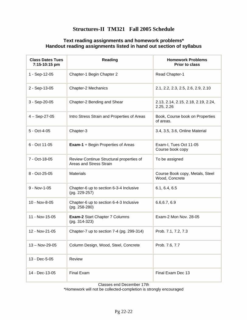
Structures-II TM321 Fall 2005 Schedule
Text reading assignments and homework problems* Handout reading assignments listed in hand out section of syllabus
Class Dates Tues
7:15-10:15 pm Reading Homework Problems
Prior to class
1 - Sep-12-05 Chapter-1 Begin Chapter 2 Read Chapter-1
2 - Sep-13-05 Chapter-2 Mechanics 2.1, 2.2, 2.3, 2.5, 2.6, 2.9, 2.10
3 - Sep-20-05 Chapter-2 Bending and Shear 2.13, 2.14, 2.15, 2.18, 2.19, 2.24, 2.25, 2.26
4 – Sep-27-05 Intro Stress Strain and Properties of Areas Book, Course book on Properties of areas.
5 - Oct-4-05 Chapter-3 3.4, 3.5, 3.6, Online Material
6 - Oct 11-05 Exam-1 + Begin Properties of Areas Exam-I, Tues Oct 11-05 Course book copy
7 - Oct-18-05 Review Continue Structural properties of Areas and Stress Strain
To be assigned
8 - Oct-25-05 Materials Course Book copy, Metals, Steel Wood, Concrete
9 - Nov-1-05 Chapter-6 up to section 6-3-4 Inclusive (pg. 229-257)
6.1, 6.4, 6.5
10 - Nov-8-05 Chapter-6 up to section 6-4-3 Inclusive (pg. 258-280)
6.6,6.7, 6.9
11 - Nov-15-05 Exam-2 Start Chapter 7 Columns (pg. 314-323)
Exam-2 Mon Nov. 28-05
12 - Nov-21-05 Chapter-7 up to section 7-4 (pg. 299-314) Prob. 7.1, 7.2, 7.3
13 – Nov-29-05 Column Design, Wood, Steel, Concrete Prob. 7.6, 7.7
13 - Dec-5-05 Review
14 - Dec-13-05 Final Exam Final Exam Dec 13
Classes end December 17th *Homework will not be collected-completion is strongly encouraged
Pg 22-22