Embed Size (px)
Citation preview

High Load CapacityCan be Used With Existing Steel
Stanchions or New Nonmetallic Stanchions
Will Not Rust or CorrodeInsulators Not RequiredExcellent Dielectric PropertiesMultiple Arm and Stanchion Lengths
AvailableMolded from UL Listed Glass
Reinforced Polymer
Underground Devices BNTNonmetallic Cable Supports:
The BNT Nonmetallic Cable SupportFor Power Manholes And VaultsBNT-S952A
STANCHION
BNT-P5CROSS PIN
BNT-A1 ARM
BNT-A2 ARM
BNT-A3 ARM
BNT Series Nonmetallic Cable Support Arms Installed in A Nonmetallic Stanchion
CATALOGNUMBER
STANDARD CARTON
QUANTITY LBS LENGTH(INCHES)
WIDTH(INCHES)
HEIGHT(INCHES)
CUBICFEET
BNT-S952A 4
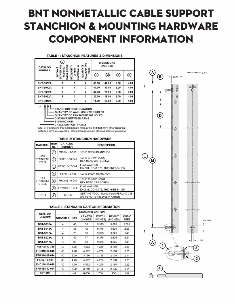
NOTE: Stanchions that accomodate more arms and that have other distance between arms are available. Consult Underground Devices sales engineering.
43
35
28
40
36
51
42
33
47
43
9.375
9.375
9.375
9.375
9.375
3.625
3.625
3.625
3.625
3.625
1.003
.826
.649
.924
.845
4
4
8
12
BNT-S942A
BNT-S932A
BNT-S922A
BNT-S912A
TABLE 3: STANDARD CARTON INFORMATION
CATALOGNUMBER
DIST
ANCE
BE
TWEE
N AR
M MO
UNTIN
G HO
LES
(INCH
ES)
L M A B
BNT-S952A 9 50.00
DIMENSIONS(INCHES)
46.00 2.00 4.00
D
BNT-S942A 9 41.00 37.00 2.00 4.00
BNT-S932A 9 32.00 28.00 2.00 4.00
BNT-S922A 9 23.00 19.00 2.00 4.00
BNT-S912A --- 14.00 10.00 2.00 4.00
TABLE 1: STANCHION FEATURES & DIMENSIONS
QUAN
TITY
OF
WALL
MOU
NTIN
G HO
LES
2
2
2
2
2
5
4
3
2
1
MAX
QUAN
TITY
OF A
RMS
ACCO
MODA
TED
MATERIAL
TABLE 2: STANCHION HARDWARE
316STAINLESS
STEEL
CATALOGNUMBER DESCRIPTION
FSSRM-12-316 1/2-13 DROP-IN ANCHOR
1/2-13 X 1-1/4" LONGHEX HEAD CAP SCREW
FHC316-16-040
FFW316-17-044
ITEMNo.
FLAT WASHERID=.531, OD=1.375, THICKNESS=.135
18-8STAINLESS
STEEL
1
2
3
1
2
3
FSRM-12-188 1/2-13 DROP-IN ANCHOR
1/2-13 X 1-1/4" LONGHEX HEAD CAP SCREW
FHC188-16-040
FFW188-17-044 FLAT WASHERID=.531, OD=1.375, THICKNESS=.135
4STEEL FRT-112 SETTING TOOL - Use to install FSRM-12-316 and FSRM-12-188 Drop-in Anchors
FHC316-16-040FSSRM-12-316
FFW316-17-044
FSRM-12-188FHC188-16-040FFW188-17-044
FRT-112
40
40
40
1
4.75
4.20
2.00
4.562
4.562
3.750
4.250
4.250
3.125
2.188
2.188
2.125
.025
.025
.014
40
40
40
4.75
4.20
2.00
4.562
4.562
4.250
4.250
2.188
2.188
.025
.025
.40 6.000 .750 .750 .002
3.750 3.125 2.125 .014
STANCHION CONFIGURATIONQUANTITY OF WALL MOUNTING HOLESQUANTITY OF ARM MOUNTING HOLESDISTANCE BETWEEN ARMSS=STANCHIONCABLE SUPPORT FAMILY
BNT NONMETALLIC CABLE SUPPORTSTANCHION & MOUNTING HARDWARE
COMPONENT INFORMATION
CATALOGNUMBER
STANDARD CART ON
QUANTITY LBS LENGTH(INCHES)
WIDTH(INCHES)
HEIGHT(INCHES)
CUBICFEET
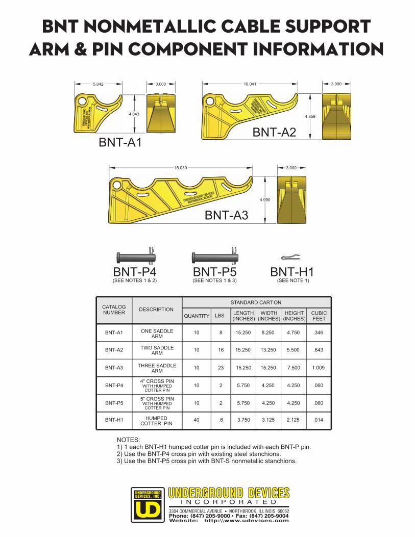
BNT-A1 10 8 15.250 8.250 4.750 .346
DESCRIPTION
ONE SADDLEARM
BNT-A2 10 16 15.250 13.250 5.500 .643TWO SADDLEARM
BNT-A3 10 23 15.250 15.250 7.500 1.009THREE SADDLEARM
BNT-P4 10 2 5.750 4.250 4.250 .0604" CROSS PINWITH HUMPEDCOTTER PIN
BNT-P5 10 2 5.750 4.250 4.250 .0605" CROSS PINWITH HUMPEDCOTTER PIN
BNT-H1 40 .6 3.750 3.125 2.125 .014HUMPEDCOTTER PIN
NOTES:1) 1 each BNT-H1 humped cotter pin is included with each BNT-P pin.2) Use the BNT-P4 cross pin with existing steel stanchions.3) Use the BNT-P5 cross pin with BNT-S nonmetallic stanchions.
3.000
4.859
10.041
BNT-A2
3.000
4.043
5.042
BNT-A1
3.00015.039
4.990
BNT-A3
BNT-P5(SEE NOTES 1 & 3)
BNT-P4(SEE NOTES 1 & 2)
BNT-H1(SEE NOTE 1)
BNT NONMETALLIC CABLE SUPPORTARM & PIN COMPONENT INFORMATION

The BNT family of cable supports meets power utility needs for a manhole cable support system that is nonmetallic and nonconductive. The nonmetallic property is the solution to steel cable rack rust and corrosion problems, while the nonconductive properties eliminate cable support grounding and insulator requirements.
A complete nonmetallic solution, consisting of BNT nonmetallic stanchions, arms and cross pins should be selected for new and replacement installations. Since BNT arms mate with many exisiting steel stanchions, retrofitting of exisitng manholes can be accomplished by initially changing out the steel arms with BNT arms. The exisitng steel stanchions may be replaced, as necessary, at a later date.
Arm installation is safe and simple - the arms are secured in place with nonmetallic pins, allowing for installation and removal of the arms without disturbing any cable.
Due to the extreme strength and rigidity of the BNT stanchions, most installations require only two bolts to secure a stanchion to the manhole wall.
BNT arms and stanchions have loading capacities comparable to similar heavy duty steel cable racks.
BNT Nonmetallic Cable Support ArmsInstalled in An Existing Steel Stanchion
BNT-P4CROSS PIN
EXISTING STEEL STANCHION
Net 30 days - $100.00 minimum net billing. All prices FOB our factory or warehouse location with freight to be charged directly by the carrier.
Claims for damages or shortages shall first be processed with carrier by consignee.
A 25% re-stocking charge will be made on orders returned, transportation prepaid, to the original shipping point following authorization from UNDERGROUND DEVICES, INC. Authorization will be granted only under the conditions that the quantity to be returned does not exceed 10% of the quantity ordered, the goods are in saleable condition in the original cartons and the request for return is made within 90 days of the shipping date.
UNDERGROUND DEVICES, INC. Warrants to the original purchaser that the goods manufactured by it are free from defects in material and workmanship for a period of one year from the date of purchase. Consequences of improper selection or installation of UNDERGROUND DEVICES product on any application over any period of time is the sole responsibility of the Purchaser or User. UNDERGROUND DEVICES liability is limited to replacement of, or credit for, defective products. UNDERGROUND DEVICES, INC. WILL IN NO EVENT BE LIABLE FOR INCIDENTAL OR CONSEQUENTIAL DAMAGES.
TERMS:
CLAIMS:
LIMITEDWARRANTY:
RETURNGOODSPOLICY: