Embed Size (px)
Citation preview

Acta Materialia 51 (2003) 5881–5905www.actamat-journals.com
The biomechanics toolbox: experimental approaches forliving cells and biomolecules�
K.J. Van Vlieta,b,∗, G. Baoc, S. Suresha
a Department of Materials Science and Engineering, Massachusetts Institute of Technology, Cambridge, MA 02139, USAb Department of Surgical Research, Children’s Hospital and Harvard Medical School, Boston, MA 02115, USA
c Department of Biomedical Engineering, Georgia Institute of Technology and Emory University, Atlanta, GA 30332, USA
Accepted 31 August 2003
Abstract
The mechanical behavior of biological materials has been studied extensively at the tissue, organ and systems levels.Emerging experimental tools, however, enable quantitative studies of deformation of individual cells and biomolecules.These approaches also facilitate the exploration of biological processes mediated by mechanical signals, with force anddisplacement resolutions of 0.1 pN and 0.1 nm, respectively. As a result of these capabilities, it is now possible toestablish the structure-function relationships among the various components of a living cell. In order to fully realizethis potential, it is necessary to critically assess the capabilities of current experimental methods in elucidating whetherand how the mechanics of living cells and biomolecules, under physiological and pathological conditions, plays a majorrole in health and disease. Here, we review the operating principles, advantages and limitations, and illustrative examplesof micro- and nano-scale mechanical testing techniques developed across many research communities to manipulatecell populations, single cells, and single biomolecules. Further, we discuss key opportunities for improved analysis ofsuch experiments, as well as future directions and applications. 2003 Acta Materialia Inc. Published by Elsevier Ltd. All rights reserved.
Keywords: Biomechanics; Macromolecular materials; Elastic behavior; Stress-rupture
1. Introduction
The structure and function of many living cellsdepend directly on their global and local mechan-ical environment. The importance of this mechan-ical stimulus can be appreciated at the tissue level
∗ Corresponding author.E-mail address: [email protected] (K.J. Van Vliet).
� The Golden Jubilee Issue—Selected topics in MaterialsScience and Engineering: Past, Present and Future, edited byS. Suresh.
1359-6454/$30.00 2003 Acta Materialia Inc. Published by Elsevier Ltd. All rights reserved.doi:10.1016/j.actamat.2003.09.001
through well-known examples such as muscle atro-phy and bone resorption in the absence of skeletalloading, and has been implicated at the cellularlevel in terms of processes including adhesion,motility and differentiation. Fundamental under-standing of these basic cellular processes, and ofthe pathological responses of the cell, will befacilitated greatly by developments in the fields ofcell and molecular biomechanics. Despite thesophistication of experimental and computationalapproaches in cell and molecular biology, themechanisms by which cells sense and respond to
5882 K.J. Van Vliet et al. / Acta Materialia 51 (2003) 5881–5905
mechanical stimuli are poorly understood. To alarge extent, the intricate coupling between the bio-chemical and mechanical processes of the cellimpedes research efforts. In particular, applicationof external mechanical stimuli can induce bio-chemical reactions, including the synthesis of newbiomolecules and the enhanced interaction amongbiomolecules that can generate mechanical forces.Likewise, changes in chemical stimuli, includingpH, temperature, and biomolecular activity, canalter the structure and mechanical integrity of thecell, even in the absence of mechanical stimuli.
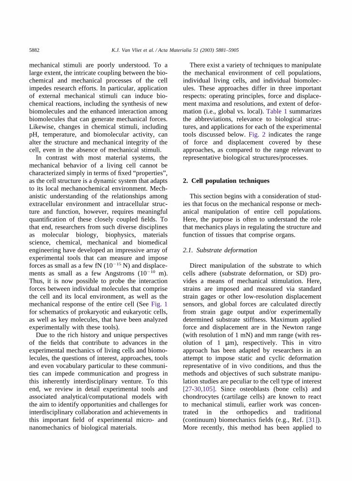
In contrast with most material systems, themechanical behavior of a living cell cannot becharacterized simply in terms of fixed “properties” ,as the cell structure is a dynamic system that adaptsto its local mechanochemical environment. Mech-anistic understanding of the relationships amongextracellular environment and intracellular struc-ture and function, however, requires meaningfulquantification of these closely coupled fields. Tothat end, researchers from such diverse disciplinesas molecular biology, biophysics, materialsscience, chemical, mechanical and biomedicalengineering have developed an impressive array ofexperimental tools that can measure and imposeforces as small as a few fN (10�15 N) and displace-ments as small as a few Angstroms (10�10 m).Thus, it is now possible to probe the interactionforces between individual molecules that comprisethe cell and its local environment, as well as themechanical response of the entire cell (See Fig. 1for schematics of prokaryotic and eukaryotic cells,as well as key molecules, that have been analyzedexperimentally with these tools).
Due to the rich history and unique perspectivesof the fields that contribute to advances in theexperimental mechanics of living cells and biomo-lecules, the questions of interest, approaches, toolsand even vocabulary particular to these communi-ties can impede communication and progress inthis inherently interdisciplinary venture. To thisend, we review in detail experimental tools andassociated analytical/computational models withthe aim to identify opportunities and challenges forinterdisciplinary collaboration and achievements inthis important field of experimental micro- andnanomechanics of biological materials.
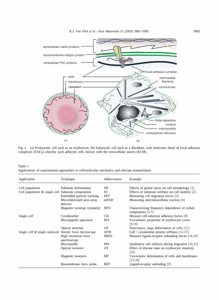
There exist a variety of techniques to manipulatethe mechanical environment of cell populations,individual living cells, and individual biomolec-ules. These approaches differ in three importantrespects: operating principles, force and displace-ment maxima and resolutions, and extent of defor-mation (i.e., global vs. local). Table 1 summarizesthe abbreviations, relevance to biological struc-tures, and applications for each of the experimentaltools discussed below. Fig. 2 indicates the rangeof force and displacement covered by theseapproaches, as compared to the range relevant torepresentative biological structures/processes.
2. Cell population techniques
This section begins with a consideration of stud-ies that focus on the mechanical response or mech-anical manipulation of entire cell populations.Here, the purpose is often to understand the rolethat mechanics plays in regulating the structure andfunction of tissues that comprise organs.
2.1. Substrate deformation
Direct manipulation of the substrate to whichcells adhere (substrate deformation, or SD) pro-vides a means of mechanical stimulation. Here,strains are imposed and measured via standardstrain gages or other low-resolution displacementsensors, and global forces are calculated directlyfrom strain gage output and/or experimentallydetermined substrate stiffness. Maximum appliedforce and displacement are in the Newton range(with resolution of 1 mN) and mm range (with res-olution of 1 µm), respectively. This in vitroapproach has been adapted by researchers in anattempt to impose static and cyclic deformationrepresentative of in vivo conditions, and thus themethods and objectives of such substrate manipu-lation studies are peculiar to the cell type of interest[27-30,105]. Since osteoblasts (bone cells) andchondrocytes (cartilage cells) are known to reactto mechanical stimuli, earlier work was concen-trated in the orthopedics and traditional(continuum) biomechanics fields (e.g., Ref. [31]).More recently, this method has been applied to
5883K.J. Van Vliet et al. / Acta Materialia 51 (2003) 5881–5905
focal adhesion complex
membrane
extracellular matrix proteins
transmembrane integrin protein
intracellular FAC proteins
actin
cytoplasm
nucleus
Golgi apparatus
endoplasmic reticulum
microtubules
intermediate
filaments
mitochondria
(a) (b)
Fig. 1. (a) Prokaryotic cell such as an erythrocyte; (b) Eukaryotic cell such as a fibroblast, with molecular detail of focal adhesioncomplexes (FACs) whereby such adherent cells interact with the extracellular matrix (ECM).
Table 1Applications of experimental approaches in cell/molecular mechanics and relevant nomenclature
Application Technique Abbreviation Example
Cell population Substrate deformation SD Effects of global stress on cell morphology [1]Cell population & single cell Substrate composition SC Effects of substrate stiffness on cell motility [2]
Embedded particle tracking EPT Measuring cell migration forces [3]Microfabricated post array mPAD Measuring inter/intracellular traction [4]detectorMagnetic twisting cytometry MTC Characterizing frequency dependence of cellulr
components [5-7]Single cell Cytodetacher CD Measure cell-substrate adhesion forces [8]
Micropipette aspiration MA Viscoelastic properties of erythrocyte cortex[9,10]
Optical stretcher OS Noncontact, large deformation of cells [11]Single cell & single molecule Atomic force microscopy AFM Cell / cytoskeletal protein stiffness [12-17]
High resolution force HRFS Measure ligand-receptor unbinding forces [18,19]spectroscopyMicroneedle MN Qualitative cell stiffness during migration [20,21]Optical tweezers OT Effect of disease state on erythrocyte elasticity
[22]Magnetic tweezers MT Viscoelastic deformation of cells and membranes
[23-26]Biomembrane force probe BFP Ligand-receptor unbinding [9]
5884 K.J. Van Vliet et al. / Acta Materialia 51 (2003) 5881–5905
Fig. 2. (a) Force range of experimental techniques and biological events; (b) Displacement range of experimental techniques anddimensions of biological structures.
studies of endothelial cells [32] and melanocytes[33] under cyclic strain, as well as stretch-inducedinjury of neurons [34].
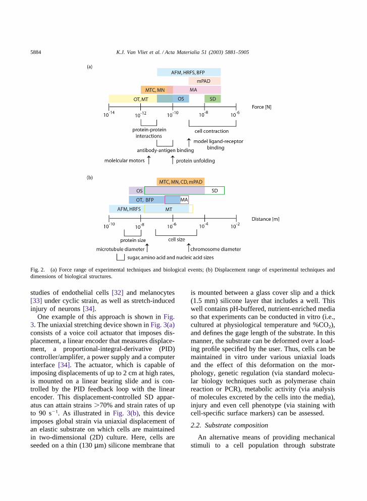
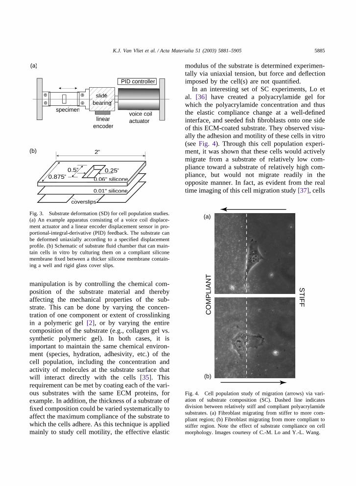
One example of this approach is shown in Fig.3. The uniaxial stretching device shown in Fig. 3(a)consists of a voice coil actuator that imposes dis-placement, a linear encoder that measures displace-ment, a proportional-integral-derivative (PID)controller/amplifer, a power supply and a computerinterface [34]. The actuator, which is capable ofimposing displacements of up to 2 cm at high rates,is mounted on a linear bearing slide and is con-trolled by the PID feedback loop with the linearencoder. This displacement-controlled SD appar-atus can attain strains �70% and strain rates of upto 90 s�1. As illustrated in Fig. 3(b), this deviceimposes global strain via uniaxial displacement ofan elastic substrate on which cells are maintainedin two-dimensional (2D) culture. Here, cells areseeded on a thin (130 µm) silicone membrane that
is mounted between a glass cover slip and a thick(1.5 mm) silicone layer that includes a well. Thiswell contains pH-buffered, nutrient-enriched mediaso that experiments can be conducted in vitro (i.e.,cultured at physiological temperature and %CO2),and defines the gage length of the substrate. In thismanner, the substrate can be deformed over a load-ing profile specified by the user. Thus, cells can bemaintained in vitro under various uniaxial loadsand the effect of this deformation on the mor-phology, genetic regulation (via standard molecu-lar biology techniques such as polymerase chainreaction or PCR), metabolic activity (via analysisof molecules excreted by the cells into the media),injury and even cell phenotype (via staining withcell-specific surface markers) can be assessed.
2.2. Substrate composition
An alternative means of providing mechanicalstimuli to a cell population through substrate
5885K.J. Van Vliet et al. / Acta Materialia 51 (2003) 5881–5905
voice coilactuator
PID controller
specimen
linearencoder
slideslidede sbearing b ng rinearbea
2"
0.8.875"0.8 0.06" siliconee0
0.01" s silicone" s e
coverslips
0.25"0.5"
(a)
(b)
Fig. 3. Substrate deformation (SD) for cell population studies.(a) An example apparatus consisting of a voice coil displace-ment actuator and a linear encoder displacement sensor in pro-portional-integral-derivative (PID) feedback. The substrate canbe deformed uniaxially according to a specified displacementprofile. (b) Schematic of substrate fluid chamber that can main-tain cells in vitro by culturing them on a compliant siliconemembrane fixed between a thicker silicone membrane contain-ing a well and rigid glass cover slips.
manipulation is by controlling the chemical com-position of the substrate material and therebyaffecting the mechanical properties of the sub-strate. This can be done by varying the concen-tration of one component or extent of crosslinkingin a polymeric gel [2], or by varying the entirecomposition of the substrate (e.g., collagen gel vs.synthetic polymeric gel). In both cases, it isimportant to maintain the same chemical environ-ment (species, hydration, adhesivity, etc.) of thecell population, including the concentration andactivity of molecules at the substrate surface thatwill interact directly with the cells [35]. Thisrequirement can be met by coating each of the vari-ous substrates with the same ECM proteins, forexample. In addition, the thickness of a substrate offixed composition could be varied systematically toaffect the maximum compliance of the substrate towhich the cells adhere. As this technique is appliedmainly to study cell motility, the effective elastic
modulus of the substrate is determined experimen-tally via uniaxial tension, but force and deflectionimposed by the cell(s) are not quantified.
In an interesting set of SC experiments, Lo etal. [36] have created a polyacrylamide gel forwhich the polyacrylamide concentration and thusthe elastic compliance change at a well-definedinterface, and seeded fish fibroblasts onto one sideof this ECM-coated substrate. They observed visu-ally the adhesion and motility of these cells in vitro(see Fig. 4). Through this cell population experi-ment, it was shown that these cells would activelymigrate from a substrate of relatively low com-pliance toward a substrate of relatively high com-pliance, but would not migrate readily in theopposite manner. In fact, as evident from the realtime imaging of this cell migration study [37], cells
ST
IFF
CO
MP
LIA
NT
(a)
(b)
Fig. 4. Cell population study of migration (arrows) via vari-ation of substrate composition (SC). Dashed line indicatesdivision between relatively stiff and compliant polyacrylamidesubstrates. (a) Fibroblast migrating from stiffer to more com-pliant region; (b) Fibroblast migrating from more compliant tostiffer region. Note the effect of substrate compliance on cellmorphology. Images courtesy of C.-M. Lo and Y.-L. Wang.
5886 K.J. Van Vliet et al. / Acta Materialia 51 (2003) 5881–5905
approaching the interface immediately changedirection and migrate opposite the region of lowercompliance. Furthermore, cells moved toward aregion of localized tension in the substrate (pullingon a blunted micropipette submerged in the gel)and away from a region of localized compression(pushing on that micropipette). Although the mol-ecular mechanism by which the cells sense the dif-ference in mechanical stiffness of the substrate isnot fully understood, related research [2] hasshown that myosin motors play a role in enablingthe cell to sense the local mechanical stiffnessthrough focal adhesion complexes (FACs) and thatincreased substrate stiffness correlates withincreased phosphorylation of tyrosine. This mol-ecular modification appears critical to the forma-tion of stable FACs as shown in Fig. 1. Thus, suchcell population studies are important in the sensethat they can show both the individual and collec-tive behavior of cells through cell/substrate interac-tions.
The methods outlined above consider the cellsin a 2D culture system, whereas cells in vivo aretypically contained within a three-dimensional(3D) ECM. In theory, each of these methods couldbe extended to 3D. In practice, however, this criti-cal aspect of the cell environment is limited by thedifficulty associated with imaging and manipulat-ing cells in 3D. Efforts to overcome this limitationwill extend the utility of such cell population stud-ies.
3. Single cell and single molecule techniques
One criticism of cell population studies such asthose described above is that, despite the ability ofsuch studies to show that applied mechanical stressalters cell structure and function, the heterogeneityamong cell responses is largely ignored. Further-more, the response of a single cell to mechanicalsignals (i.e., mechanisms of cellular deformationand mechanotransduction) cannot be decoupledeasily from the response of the entire population.In this section, we discuss advances in the manipu-lation of individual living cells, whereby themanipulation of the environment of a single cellcan help elucidate how a cell receives and pro-
cesses extracellular mechanical signals. Further,we illustrate how some of the same experimentalmethods can be applied to the studies of single-molecule biomechanics.
3.1. Embedded particle tracking
By embedding micro-scale beads within a poly-meric substrate, traction forces exerted by adherentcells can be measured at many points of cell-sur-face contact. Here, the beads serve as fiduciarymarkers within a flexible membrane [38]. The dis-placement of the beads x is measured optically, andthe corresponding force F is calculated via theexperimentally determined elastic stiffness k ofthe membrane:
F � �kx. (1)
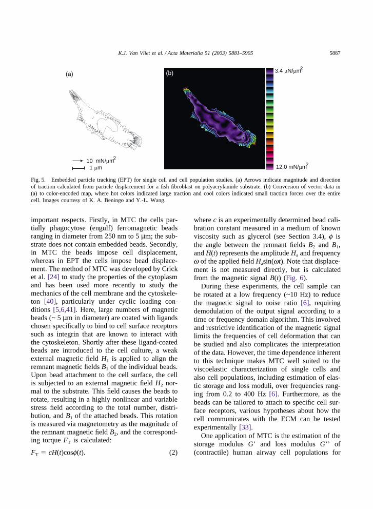
As this force is derived from the traction betweenthe adherent cell and its substrate, this method isalso commonly referred to as traction forcemicroscopy [39]. The displacement resolution ofthis technique is limited by the available optics;the force resolution is limited by available opticsas well as the accuracy of k. The value of k canbe estimated by simple mechanical tension experi-ments such as the optically measured deflection ofthe membrane via a known mass [2], or via tech-niques such as microneedle (MN, Section 3.7) ornanoindentation, and typically neglect elastic non-linearity and time-dependent responses of themembrane. Further, the deconvolution of bead dis-placement to force maps has been a major analyti-cal challenge but, as shown in Fig. 5, can now beresolved at the sub-micron scale to identify mol-ecular sites of cell-substrate adhesion that compriseFACs. Note that this technique, like the majorityof substrate interaction techniques, is confined toadherent cells in 2D culture. In principle, opticaldeconvolution of 3D bead displacement wouldallow through-thickness determination of tractionforces in 3D experiments.
3.2. Magnetic twisting cytometry
Magnetic twisting cytometry (MTC) also relieson the use of beads to measure pointwise displace-ment, but this method differs from EPT in two
5887K.J. Van Vliet et al. / Acta Materialia 51 (2003) 5881–5905
10 mN/µm2
1 µm
3.4 µN/µm2
12.0 mN/µm2
(a) (b)
Fig. 5. Embedded particle tracking (EPT) for single cell and cell population studies. (a) Arrows indicate magnitude and directionof traction calculated from particle displacement for a fish fibroblast on polyacrylamide substrate. (b) Conversion of vector data in(a) to color-encoded map, where hot colors indicated large traction and cool colors indicated small traction forces over the entirecell. Images courtesy of K. A. Beningo and Y.-L. Wang.
important respects. Firstly, in MTC the cells par-tially phagocytose (engulf) ferromagnetic beadsranging in diameter from 250 nm to 5 µm; the sub-strate does not contain embedded beads. Secondly,in MTC the beads impose cell displacement,whereas in EPT the cells impose bead displace-ment. The method of MTC was developed by Cricket al. [24] to study the properties of the cytoplasmand has been used more recently to study themechanics of the cell membrane and the cytoskele-ton [40], particularly under cyclic loading con-ditions [5,6,41]. Here, large numbers of magneticbeads (~ 5 µm in diameter) are coated with ligandschosen specifically to bind to cell surface receptorssuch as integrin that are known to interact withthe cytoskeleton. Shortly after these ligand-coatedbeads are introduced to the cell culture, a weakexternal magnetic field H1 is applied to align theremnant magnetic fields B1 of the individual beads.Upon bead attachment to the cell surface, the cellis subjected to an external magnetic field H2 nor-mal to the substrate. This field causes the beads torotate, resulting in a highly nonlinear and variablestress field according to the total number, distri-bution, and B1 of the attached beads. This rotationis measured via magnetometry as the magnitude ofthe remnant magnetic field B2, and the correspond-ing torque FT is calculated:
FT � cH(t)cosf(t). (2)
where c is an experimentally determined bead cali-bration constant measured in a medium of knownviscosity such as glycerol (see Section 3.4), f isthe angle between the remnant fields B2 and B1,and H(t) represents the amplitude Ha and frequencyw of the applied field Hasin(wt). Note that displace-ment is not measured directly, but is calculatedfrom the magnetic signal B(t) (Fig. 6).
During these experiments, the cell sample canbe rotated at a low frequency (~10 Hz) to reducethe magnetic signal to noise ratio [6], requiringdemodulation of the output signal according to atime or frequency domain algorithm. This involvedand restrictive identification of the magnetic signallimits the frequencies of cell deformation that canbe studied and also complicates the interpretationof the data. However, the time dependence inherentto this technique makes MTC well suited to theviscoelastic characterization of single cells andalso cell populations, including estimation of elas-tic storage and loss moduli, over frequencies rang-ing from 0.2 to 400 Hz [6]. Furthermore, as thebeads can be tailored to attach to specific cell sur-face receptors, various hypotheses about how thecell communicates with the ECM can be testedexperimentally [33].
One application of MTC is the estimation of thestorage modulus G’ and loss modulus G’’ of(contractile) human airway cell populations for

5888 K.J. Van Vliet et al. / Acta Materialia 51 (2003) 5881–5905
B
magnetometer
H
φ
magnetometer
aligned magnetic beads
ω
(a)
(b)
Fig. 6. Magnetic twisting cytometry (MTC) for single cellstudies. (a) Micro- to nanoscale ferromagnetic beads attachaspecifically or specifically to the cell membrane and are brieflymagnetized to align magnetic dipoles. (b) A magnetic field His applied to induce bead rotation φ, and the corresponding rem-nant field of this rotation B is measured via a magnetometer.To increase the magnetic signal/noise ratio, the sample isrotated about the H direction at an angular velocity ω.(AfterRef. [6]).
which magnetic beads are bound to transmembraneintegrin receptors, components of the FACs asshown in Fig. 1 [7]. Maksym et al. found that thesemoduli were weakly dependent on frequency, andtracked changes in these parameters as a functionof chemical environment to show that cytoskeletaldisruption reduces the storage and dissipation ofenergy proportionally in this cultured cell popu-lation.
3.3. Micropatterned substrates
Several cell manipulation technologies havebeen enabled by the development of thin film litho-graphic techniques. Here, micropatterned sub-strates are fabricated to allow pointwise control ofcell adhesion and traction measurement throughdisplacement of the pattern features [42-44]. Oneinteresting example of this approach is themicrofabricated post array detector (mPAD) . Tanet al. [4] have produced an array of independentlydeforming posts onto which cells can adhere by
using standard photolithography to create a siliconreplica, then casting an elastomer (PDMS) withinthat replica to form a pattern of flexible micron-scale cantilevers (oriented vertically), and finallymicrocontact printing [45] the cantilever ends withECM protein to facilitate cell adhesion. With thispatterned substrate, these authors have shown thatthe cell forms FACs at the points of contact withthese cantilevers and deflects them toward the cellcenter. The stiffness of the cantilevers can be con-trolled by varying either the stiffness of the elasto-mer or the geometry of the cantilever. The deflec-tion x imposed by the cell, measured via imageanalysis, has been related to the force F via thestandard linear elastic beam theory:
F � 3EIx /L3 (3)
where E is the (time-independent) elastic modulus,I is moment of inertia, and L is and the cantileverbeam length. Here, the strain imposed on a parti-cular cell cannot be modulated in a given experi-ment; it is set by the compliance of the cantileverarray. In addition, the deformation is quantifiedonly in the plane of the cell/post interface; changesnormal to this plane (cell thickness) cannot beassessed. However, this method is advantageous inthat mPAD resolves the deformation imposed bythe cell at sub-cellular (9 µm) scales, and can thusmap the corresponding, spatially varying tractionforces with a resolution of 12 nN, as shown in Fig.7. It has been shown [4] that the traction forcesincreased as the FAC size increased, at least as thisFAC size was quantified through fluorescence ofa particular ECM protein. Although they did notconsider the deformation in terms of stress andstrain, Tan et al. reported that when they con-strained the area over which cells could adhere (bydefining the number of ECM-coated posts),“small” cells exhibited less traction force than“ large” cells, indicating that the number of FACsthat the cell can form contributes directly to thelevel of stress that the cell can impose on its sub-strate. Note that Eq. (3) is a time-independent, lin-ear relation, and its application in the mPAD analy-sis neglects the hyperelastic and viscoelasticdeformation/creep of the elastomer. This consider-ation may be especially important when examining

5889K.J. Van Vliet et al. / Acta Materialia 51 (2003) 5881–5905
Fig. 7. The Microfabricated Post Array Detector (mPAD), an example of micropatterned substrates for cell population and singlecell studies. (a) NIH3T3 fibroblasts on post array of 9 µm spacing; (b) Phase contrast image of single fibroblast; (c) Vector map offorce calculated from post deflection. Scalebar = 50 nN. Images courtesy of J. Tan and C. Chen.
the response of the cell over time spans of chemi-cal exposure.
3.4. Micropipette aspiration
The micropipette aspiration technique (MA) hasbeen used widely to study time-dependent defor-mation of living, individual cells subjected toextracellular pressure. Here, the cell is drawn into aglass tube, the inner diameter of which is a chosenfraction of the nominal diameter of the cell, viastepwise application of aspiration pressure �p (i.e.,suction). Applied aspiration pressure ranges from0.1-1000 Pa, with resolution of 0.1 Pa [10,46]. Thispressure is maintained over a specified duration,
and the attendant extension of the cell into the pip-ette is monitored via optical microscopy. Displace-ment of the cell membrane is tracked by lightmicroscopy with a claimed resolution of ± 25 nm[46]. The micropipettes and glass walls that definethe fluid cell of the experiment are coated with 1%agar to inhibit cell adhesion. Thus, MA enablesreal-time correlation of pressure and whole-celldeformation. Force F is related to applied aspir-ation pressure and membrane deflection as:
F � pR2p�p(1�[x�p /x�a] (4)
where Rp is the micropipette radius, and x�p andx�a are the velocities of the cell in the presence andabsence of applied aspiration pressure �p, respect-
5890 K.J. Van Vliet et al. / Acta Materialia 51 (2003) 5881–5905
ively [47]. Through application of a chosen visco-elastic model for the cell membrane, MA-induceddeformation is used to calculate elastic modulus E,apparent viscosity µ for the cell membrane andtime constants of deformation and/or relaxation t.
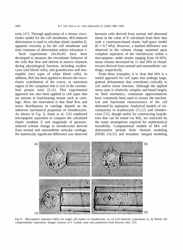
Such experiments [46,48,49] have beendeveloped to measure the viscoelastic behavior ofthe cells that flow and deform in narrow channelsduring physiological function, including erythro-cytes (red blood cells), and granulocytes and neu-trophils (two types of white blood cells). Inaddition, MA has been applied to discern the visco-elastic contribution of the cortex, or outermostregion of the cytoplasm that is rich in the cytoske-letal protein actin [9,10]. This experimentalapproach has also been applied to cell types thatare present in load-bearing tissues such as carti-lage. Here, the motivation is that fluid flow andstress distributions in cartilage depend on theunknown mechanical properties of chondrocytes.As shown in Fig. 8, Jones et al. [50] employedmicropipette aspiration to compare the calculatedelastic modulus E and magnitude of pressure-induced volume change in chondrocytes derivedfrom normal and osteoarthritic articular cartilage.No statistically significant difference was observed
(a) (b)
(c) (d)
Fig. 8. Micropipette aspiration (MA) for single cell studies in chondrocytes. (a, b) Cell elasticity experiment; (c, d) Whole cellcompressibility experiment. Images courtesy of F. Guilak, used with permission from Elsevier, Ref. [50].
between cells derived from normal and abnormaltissue in the value of E calculated from their datawith a continuum-based elastic half-space model(E = 0.7 kPa). However, a marked difference wasobserved in the volume change sustained uponcomplete aspiration of the chondrocyte within amicropipette: under strains ranging from 10-45%,mean volume decreased by 11 and 20% in chond-rocytes derived from normal and osteoarthritic car-tilage, respectively.
From these examples, it is clear that MA is auseful approach for cell types that undergo large,general deformation that contributes critically tocell and/or tissue function. Although the appliedstress state is relatively complex and based largelyon fluid mechanics, continuum approximationshave commonly been used to extract the mechan-ical and functional characteristics of the celldeformed by aspiration. Analytical models of vis-coelasticity in erythrocytes [51,52] and chondro-cytes [53], though useful for constructing hypoth-eses that can be tested via MA, are restricted bythe many assumptions required for mathematicaltractability. Computational models of MA celldeformation include finite element modeling(FEM) [54,55] and boundary integral modeling
5891K.J. Van Vliet et al. / Acta Materialia 51 (2003) 5881–5905
(BIM) [56,57]. Increasingly, these models incor-porate biphasic, or layered, structural assumptionsthat delineate the contributions of the cortex and ofthe cytoplasm. As the predictions of these modelsdepend on the choice of constitutive model, includ-ing the value of mechanical properties and timeconstants, the chief use of these simulations is tofit experimental data to a given constitutive modeland thereby obtain estimates for elastic and viscousproperties. Clearly, the choice of constitutivemodel dramatically affects the value of fitted para-meters, i.e., the calculated viscoelastic character-istics. While the vast majority of constitutive mod-els used to interpret MA aspiration experimentshave been based on continuum formulations, mol-ecular dynamics analysis of the cell membranespectrin network using Monte Carlo simulationshave also been developed in recent years [58-60].
3.5. Optical traps
Several experimental approaches developed toinvestigate single cell mechanics are based on thecontrolled displacement of dielectric objects thatare either attached to the cell membrane or placedinside the cell [61,62]. Such devices, termed sin-gle-beam gradient optical traps (OT), opticaltweezers, laser tweezers or optical clamps, rely onthe conservation of photon momentum. That is,when transmitted through a dielectric object ofhigh refractive index no and of radius R � laserwavelength l, the photons from a focused laserbeam are subject to a change in momentum as aconsequence of refraction when the beam entersand exits the object. This momentum change, inturn, exerts a restoring force Fg on the object(recoil) in the direction of greater photon flux (i.e.,toward the center of the photon intensity gradientthat is in fact the focal point of the laser beam).This optical trap is stabilized with respect to repul-sive forces when the gradient along the axis of thelaser dominates over all other gradients, which iswhy lenses of large numerical aperture (NA) arerequired. As a result, the dielectric object movestoward the laser focal point under a force Fg, andcan thus be used to impose force through trans-lation of the focal point or to measure externally
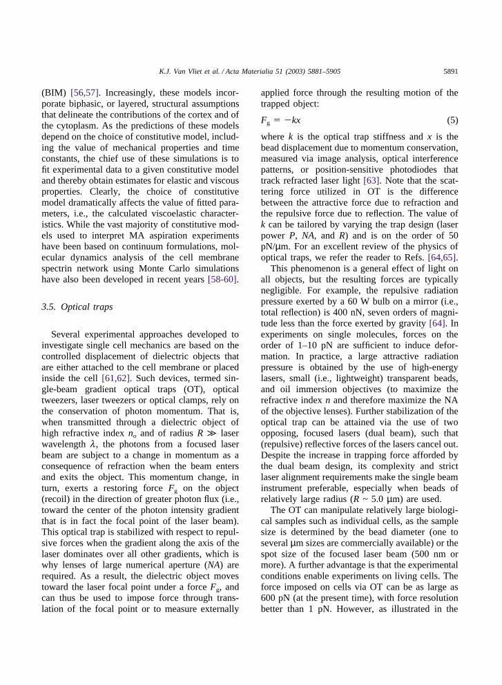
applied force through the resulting motion of thetrapped object:
Fg � �kx (5)
where k is the optical trap stiffness and x is thebead displacement due to momentum conservation,measured via image analysis, optical interferencepatterns, or position-sensitive photodiodes thattrack refracted laser light [63]. Note that the scat-tering force utilized in OT is the differencebetween the attractive force due to refraction andthe repulsive force due to reflection. The value ofk can be tailored by varying the trap design (laserpower P, NA, and R) and is on the order of 50pN/µm. For an excellent review of the physics ofoptical traps, we refer the reader to Refs. [64,65].
This phenomenon is a general effect of light onall objects, but the resulting forces are typicallynegligible. For example, the repulsive radiationpressure exerted by a 60 W bulb on a mirror (i.e.,total reflection) is 400 nN, seven orders of magni-tude less than the force exerted by gravity [64]. Inexperiments on single molecules, forces on theorder of 1–10 pN are sufficient to induce defor-mation. In practice, a large attractive radiationpressure is obtained by the use of high-energylasers, small (i.e., lightweight) transparent beads,and oil immersion objectives (to maximize therefractive index n and therefore maximize the NAof the objective lenses). Further stabilization of theoptical trap can be attained via the use of twoopposing, focused lasers (dual beam), such that(repulsive) reflective forces of the lasers cancel out.Despite the increase in trapping force afforded bythe dual beam design, its complexity and strictlaser alignment requirements make the single beaminstrument preferable, especially when beads ofrelatively large radius (R ~ 5.0 µm) are used.
The OT can manipulate relatively large biologi-cal samples such as individual cells, as the samplesize is determined by the bead diameter (one toseveral µm sizes are commercially available) or thespot size of the focused laser beam (500 nm ormore). A further advantage is that the experimentalconditions enable experiments on living cells. Theforce imposed on cells via OT can be as large as600 pN (at the present time), with force resolutionbetter than 1 pN. However, as illustrated in the
5892 K.J. Van Vliet et al. / Acta Materialia 51 (2003) 5881–5905
example below, quantitative use of OT requiresthat the refractive indices of the trapped object (inthis example, the attached bead) no and surround-ing environment nm be uniform, that no � nm, thatthe biological object be as symmetric as possible,and that the biological object be sufficiently com-pliant that the laser power P required to deform itwill not impart radiation damage. For thesereasons, mechanical studies via OT are most appli-cable to cells located in fluid suspension in vivo,such as blood cells and immune response (T- andB-) cells.
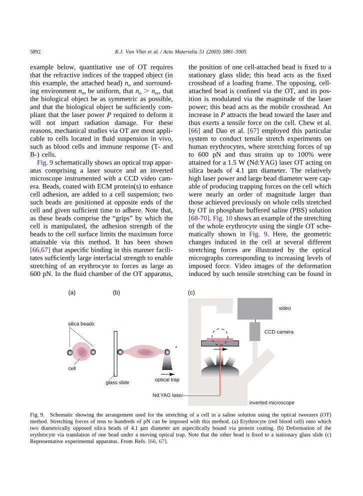
Fig. 9 schematically shows an optical trap appar-atus comprising a laser source and an invertedmicroscope instrumented with a CCD video cam-era. Beads, coated with ECM protein(s) to enhancecell adhesion, are added to a cell suspension; twosuch beads are positioned at opposite ends of thecell and given sufficient time to adhere. Note that,as these beads comprise the “grips” by which thecell is manipulated, the adhesion strength of thebeads to the cell surface limits the maximum forceattainable via this method. It has been shown[66,67] that aspecific binding in this manner facili-tates sufficiently large interfacial strength to enablestretching of an erythrocyte to forces as large as600 pN. In the fluid chamber of the OT apparatus,
(a) (b)
optical trap
Nd:YAG laser
CCD camera
inverted microscope
video
cell
silica beads
glass slide
(c)
Fig. 9. Schematic showing the arrangement used for the stretching of a cell in a saline solution using the optical tweezers (OT)method. Stretching forces of tens to hundreds of pN can be imposed with this method. (a) Erythrocyte (red blood cell) onto whichtwo diametrically opposed silica beads of 4.1 µm diameter are aspecifically bound via protein coating. (b) Deformation of theerythrocyte via translation of one bead under a moving optical trap. Note that the other bead is fixed to a stationary glass slide (c)Representative experimental apparatus. From Refs. [66, 67].
the position of one cell-attached bead is fixed to astationary glass slide; this bead acts as the fixedcrosshead of a loading frame. The opposing, cell-attached bead is confined via the OT, and its pos-ition is modulated via the magnitude of the laserpower; this bead acts as the mobile crosshead. Anincrease in P attracts the bead toward the laser andthus exerts a tensile force on the cell. Chew et al.[66] and Dao et al. [67] employed this particularsystem to conduct tensile stretch experiments onhuman erythrocytes, where stretching forces of upto 600 pN and thus strains up to 100% wereattained for a 1.5 W (Nd:YAG) laser OT acting onsilica beads of 4.1 µm diameter. The relativelyhigh laser power and large bead diameter were cap-able of producing trapping forces on the cell whichwere nearly an order of magnitude larger thanthose achieved previously on whole cells stretchedby OT in phosphate buffered saline (PBS) solution[68-70]. Fig. 10 shows an example of the stretchingof the whole erythrocyte using the single OT sche-matically shown in Fig. 9. Here, the geometricchanges induced in the cell at several differentstretching forces are illustrated by the opticalmicrographs corresponding to increasing levels ofimposed force. Video images of the deformationinduced by such tensile stretching can be found in

5893K.J. Van Vliet et al. / Acta Materialia 51 (2003) 5881–5905
Fig. 10. Optical micrographs showing the deformed geometryof a human red blood cell in a phosphate buffered saline sol-ution at room temperature that is subjected to large deformationin direct tension using optical tweezers (OT). The bead on theright is held fixed to a glass slide while the one on the left istrapped with a laser beam; the displacement of the beam causesthe bead to move, thereby stretching the cell. The diameters ofthe beads is 4.1 µm. From Refs. [66, 67].
the supplementary material archived electronicallyin [67].
The force calibration procedure for OT is similarto that employed for MTC and magnetic traps(MT), where drag force is calculated as a functionof bead displacement in a solution of known vis-cosity such as glycerol or PBS [66-70]. In OT, themicrobead is trapped in PBS at a certain laserpower, and a flow chamber imposes increasingshear flow on the bead as the bead is displacedfrom the OT as a consequence of the drag forceF, which is estimated from Stokes’ law as:
F � 6pRhfv (6)
where R is the bead radius, hf is the PBS viscosity,and ν is the velocity of the PBS across the bead.In practice, Eq. (6) must be modified to accountfor the boundary effects of a closed system. Trap-ping force can thus be calculated for experimentsconducted at the same solution viscosity, known R,and experimentally measured ν. Alternatively, trapstiffness k can be calculated via the power spectraldensity (frequency dependence of thermaloscillations) of the bead and force F calculated via
Eq. (5) for experimentally measured bead displace-ment x.
In addition to monotonic loading, cyclic andstepwise loading can be imposed via an acousto-optical modulator [69], a standard laser optics con-trol component. Optical tweezers have also beenused to impose stretching forces at more than twolocations on the cell membrane by proper adhesionof multiple beads at predetermined sites on the cellmembrane, in order to approximate loading statessuch as equibiaxial tension [71], or by multipli-cation of a single OT via computer generated holo-grams [72]. This possibility affords considerableflexibility in the control of stress state during thedeformation of the entire cell that, in turn, offersa useful experimental tool for probing the consti-tutive response of the cell membrane. These capa-bilities point to potential opportunities for estab-lishing molecular level connections betweenstructural changes in the cell and the progression ofdiseases. Certainly, the nonlinear and non-uniformstress distribution that arises due to the point load-ing inherent in bead-mediated OT represents a cur-rent challenge in the calculation of mechanicalparameters.
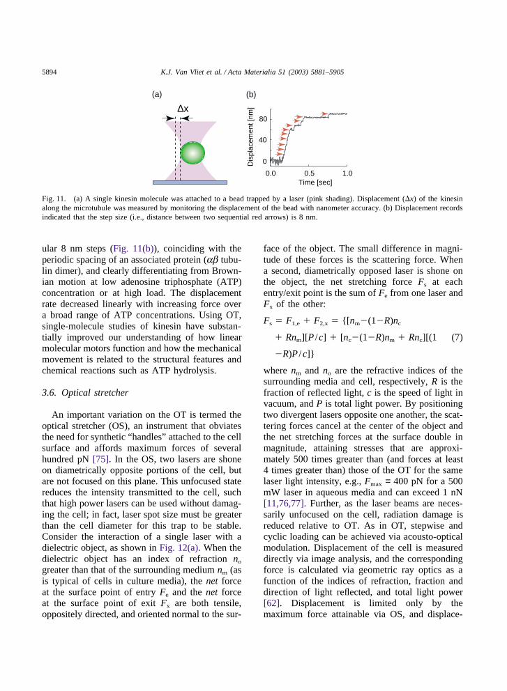
Due to its high accuracy in force measurement,OT has been used extensively in single-moleculestudies [73]. Typically, biomolecules are bound topolystyrene or silica beads (~1 µm in diameter).An optical trap can then be used to steer a bead tointeract with a partner molecule attached to a glasscoverslip or another bead. Upon binding betweenthe two molecules, the forces and displacementsinvolved can be measured, and the interaction canbe perturbed mechanically by moving the trap. Per-haps the most intensive applications of opticaltweezers have been studies on the linear motor pro-tein kinesin that transports vesicles and movesalong microtubules for up to several µm before dis-sociating [73]. To characterize the motion of kine-sin, Svoboda et al. [74] attached kinesin at lowdensity to silica beads, optically trapped a bead,and moved it near a microtubule that was fixedon a microscope coverslip. The displacement x ofkinesin along the microtubule was measured bymonitoring the displacement of the bead with nan-ometer accuracy (Fig. 11(a)). The kinesin moleculewas found to move along a microtubule with reg-
5894 K.J. Van Vliet et al. / Acta Materialia 51 (2003) 5881–5905
Time [sec]0.50.0 1.0
Dis
plac
emen
t [nm
]
80
40
0
∆x
(a) (b)
Fig. 11. (a) A single kinesin molecule was attached to a bead trapped by a laser (pink shading). Displacement (�x) of the kinesinalong the microtubule was measured by monitoring the displacement of the bead with nanometer accuracy. (b) Displacement recordsindicated that the step size (i.e., distance between two sequential red arrows) is 8 nm.
ular 8 nm steps (Fig. 11(b)), coinciding with theperiodic spacing of an associated protein (ab tubu-lin dimer), and clearly differentiating from Brown-ian motion at low adenosine triphosphate (ATP)concentration or at high load. The displacementrate decreased linearly with increasing force overa broad range of ATP concentrations. Using OT,single-molecule studies of kinesin have substan-tially improved our understanding of how linearmolecular motors function and how the mechanicalmovement is related to the structural features andchemical reactions such as ATP hydrolysis.
3.6. Optical stretcher
An important variation on the OT is termed theoptical stretcher (OS), an instrument that obviatesthe need for synthetic “handles” attached to the cellsurface and affords maximum forces of severalhundred pN [75]. In the OS, two lasers are shoneon diametrically opposite portions of the cell, butare not focused on this plane. This unfocused statereduces the intensity transmitted to the cell, suchthat high power lasers can be used without damag-ing the cell; in fact, laser spot size must be greaterthan the cell diameter for this trap to be stable.Consider the interaction of a single laser with adielectric object, as shown in Fig. 12(a). When thedielectric object has an index of refraction no
greater than that of the surrounding medium nm (asis typical of cells in culture media), the net forceat the surface point of entry Fe and the net forceat the surface point of exit Fx are both tensile,oppositely directed, and oriented normal to the sur-
face of the object. The small difference in magni-tude of these forces is the scattering force. Whena second, diametrically opposed laser is shone onthe object, the net stretching force Fs at eachentry/exit point is the sum of Fe from one laser andFx of the other:
Fs � F1,e � F2,x � {[nm�(1�R)nc
� Rnm][P /c] � [nc�(1�R)nm � Rnc][(1 (7)
�R)P /c]}
where nm and no are the refractive indices of thesurrounding media and cell, respectively, R is thefraction of reflected light, c is the speed of light invacuum, and P is total light power. By positioningtwo divergent lasers opposite one another, the scat-tering forces cancel at the center of the object andthe net stretching forces at the surface double inmagnitude, attaining stresses that are approxi-mately 500 times greater than (and forces at least4 times greater than) those of the OT for the samelaser light intensity, e.g., Fmax = 400 pN for a 500mW laser in aqueous media and can exceed 1 nN[11,76,77]. Further, as the laser beams are neces-sarily unfocused on the cell, radiation damage isreduced relative to OT. As in OT, stepwise andcyclic loading can be achieved via acousto-opticalmodulation. Displacement of the cell is measureddirectly via image analysis, and the correspondingforce is calculated via geometric ray optics as afunction of the indices of refraction, fraction anddirection of light reflected, and total light power[62]. Displacement is limited only by themaximum force attainable via OS, and displace-

5895K.J. Van Vliet et al. / Acta Materialia 51 (2003) 5881–5905
(b) (c)
no
nm no<
F2,x
cell
divergent lasers(a)
F2,e
F1,xF1,e
21
Fig. 12. Optical stretcher (OS) for noncontact single cell stud-ies. (a) Schematic of operating principles. An unfocused laserexerts net tensile forces due to refraction when a laser beamenters Fe and exits Fx the cell surface. The total stretching forceFs due to diametrically opposed lasers is the sum of the nettensile force of exit from one laser (e.g., F1,e) and the net ten-sile force of entry from the other laser (e.g., F2,x). In order touse ray optics to calculate these forces, it is necessary that thebiological object be fairly symmetric, that the refractive indicesof the object no and of the surrounding media nm be spatiallyuniform, and that nm � no. (b) Neutrophil (white blood cell)in optical trap of 150 mW laser power; (c) Uniaxial, noncontactstretching of this neutrophil via 1.1 W laser power. Photographscourtesy of J. Guck and J. Kas.
ment resolution is dependent on the signal/noiseratio of the position analysis method (e.g.,measurement via standard optical image trackingof a single point implies resolution on the order of25 nm, whereas position sensitive photodiodes canyield resolution better than 1 nm). Calculations offorce are derived from analytical formulations thatare applicable to objects of high symmetry (e.g.,spheres), and uniform optical density (e.g., prokar-yotic cells). As a result, cells that exhibit aniso-
tropic shape or internal structure, including adher-ent cells on substrates, are not easily analyzed viathis method. Improved analyses of the relevantlaser optics that will relax these constraints are inprogress [106]. Further, unlike OT, OS is notamenable to single molecule studies.
Note that OS requires that the sample have agreater refractive index than its surrounding media,that no is homogeneous across the biological struc-ture, and that the laser intensity does not destabil-ize the structure. Guck et al. have shown that theserequirements are met, and strains of 160% areattainable, for (procaryotic) RBCs and (eucaryotic)PC12 cells and neutrophils [11,75-82], and Mooreet al. [82] have shown that OS is sufficiently sensi-tive to detect changes in the deformability of cellsas a function of cancer progression. As shown inFigs. 12(b) and (c), OS imposes sufficiently large,uniaxial strains to deform eucaryotic cells withextensive and dynamic cytosekeletal protein net-works, such as neutrophils. Further application ofthis approach may include high frequency (kHz)mechanical oscillation of mechanosensory cells, aswell as flow-assisted cell sorting based on disease-related changes in mechanical stiffness [106].
3.7. Magnetic traps
A further variation on the OT is a magnetic trapor tweezers (MT) [83,84]. Here, magnetic beads(250 nm to 5 µm in diameter) serve as “grips”which, under electromagnetic field gradients thatimpose a local magnetic force on these beads,impose displacement. These beads can be attachedthrough ligand-specific or aspecific binding to acell surface for single cell studies [23,25,26], orattached through specific chemical functionaliz-ation to one end of nucleic acids [83,84] or biomo-lecules [85] that are fixed at the other end to a rigidsurface. The magnitude of the force is controlleddirectly by and calibrated according to field inten-sity (i.e., electromagnetic coil current), and thebead position is maintained in a feedback loop withreal-time image analysis, effectively trapping thebead in a potential well. Two advantages of thisapproach over OT are that out-of-plane rotationsand thus torque can be considered (as the magneticfield contains an angular component), and that the
5896 K.J. Van Vliet et al. / Acta Materialia 51 (2003) 5881–5905
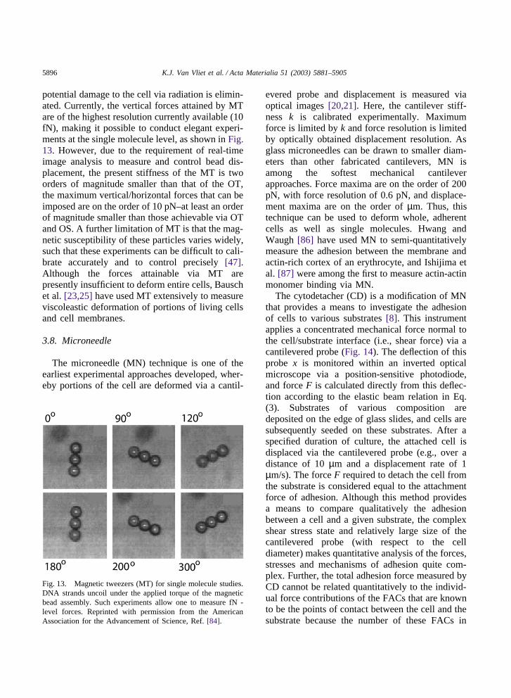
potential damage to the cell via radiation is elimin-ated. Currently, the vertical forces attained by MTare of the highest resolution currently available (10fN), making it possible to conduct elegant experi-ments at the single molecule level, as shown in Fig.13. However, due to the requirement of real-timeimage analysis to measure and control bead dis-placement, the present stiffness of the MT is twoorders of magnitude smaller than that of the OT,the maximum vertical/horizontal forces that can beimposed are on the order of 10 pN–at least an orderof magnitude smaller than those achievable via OTand OS. A further limitation of MT is that the mag-netic susceptibility of these particles varies widely,such that these experiments can be difficult to cali-brate accurately and to control precisely [47].Although the forces attainable via MT arepresently insufficient to deform entire cells, Bauschet al. [23,25] have used MT extensively to measureviscoleastic deformation of portions of living cellsand cell membranes.
3.8. Microneedle
The microneedle (MN) technique is one of theearliest experimental approaches developed, wher-eby portions of the cell are deformed via a cantil-
Fig. 13. Magnetic tweezers (MT) for single molecule studies.DNA strands uncoil under the applied torque of the magneticbead assembly. Such experiments allow one to measure fN -level forces. Reprinted with permission from the AmericanAssociation for the Advancement of Science, Ref. [84].
evered probe and displacement is measured viaoptical images [20,21]. Here, the cantilever stiff-ness k is calibrated experimentally. Maximumforce is limited by k and force resolution is limitedby optically obtained displacement resolution. Asglass microneedles can be drawn to smaller diam-eters than other fabricated cantilevers, MN isamong the softest mechanical cantileverapproaches. Force maxima are on the order of 200pN, with force resolution of 0.6 pN, and displace-ment maxima are on the order of µm. Thus, thistechnique can be used to deform whole, adherentcells as well as single molecules. Hwang andWaugh [86] have used MN to semi-quantitativelymeasure the adhesion between the membrane andactin-rich cortex of an erythrocyte, and Ishijima etal. [87] were among the first to measure actin-actinmonomer binding via MN.
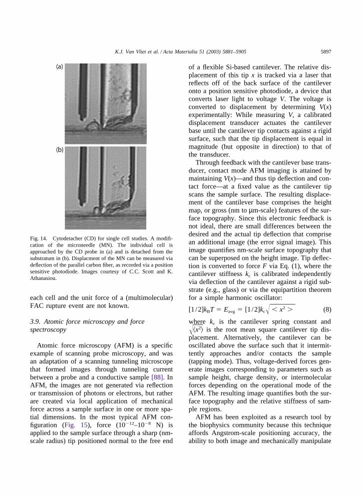
The cytodetacher (CD) is a modification of MNthat provides a means to investigate the adhesionof cells to various substrates [8]. This instrumentapplies a concentrated mechanical force normal tothe cell/substrate interface (i.e., shear force) via acantilevered probe (Fig. 14). The deflection of thisprobe x is monitored within an inverted opticalmicroscope via a position-sensitive photodiode,and force F is calculated directly from this deflec-tion according to the elastic beam relation in Eq.(3). Substrates of various composition aredeposited on the edge of glass slides, and cells aresubsequently seeded on these substrates. After aspecified duration of culture, the attached cell isdisplaced via the cantilevered probe (e.g., over adistance of 10 µm and a displacement rate of 1µm/s). The force F required to detach the cell fromthe substrate is considered equal to the attachmentforce of adhesion. Although this method providesa means to compare qualitatively the adhesionbetween a cell and a given substrate, the complexshear stress state and relatively large size of thecantilevered probe (with respect to the celldiameter) makes quantitative analysis of the forces,stresses and mechanisms of adhesion quite com-plex. Further, the total adhesion force measured byCD cannot be related quantitatively to the individ-ual force contributions of the FACs that are knownto be the points of contact between the cell and thesubstrate because the number of these FACs in
5897K.J. Van Vliet et al. / Acta Materialia 51 (2003) 5881–5905
Fig. 14. Cytodetacher (CD) for single cell studies. A modifi-cation of the microneedle (MN). The individual cell isapproached by the CD probe in (a) and is detached from thesubstratum in (b). Displacment of the MN can be measured viadeflection of the parallel carbon fiber, as recorded via a positionsensitive photodiode. Images courtesy of C.C. Scott and K.Athanasiou.
each cell and the unit force of a (multimolecular)FAC rupture event are not known.
3.9. Atomic force microscopy and forcespectroscopy
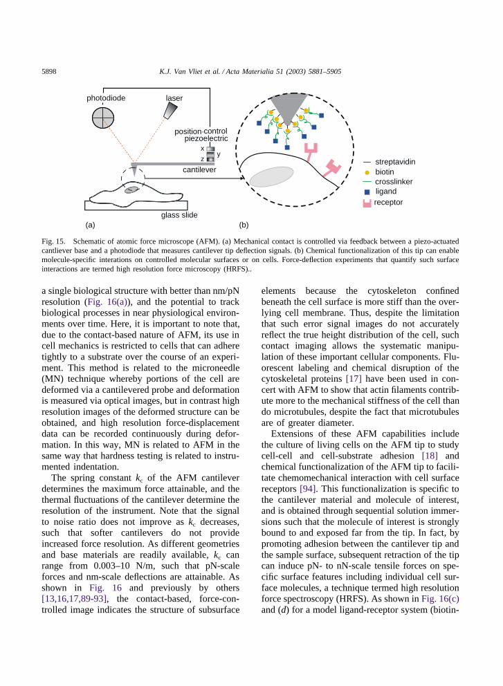
Atomic force microscopy (AFM) is a specificexample of scanning probe microscopy, and wasan adaptation of a scanning tunneling microscopethat formed images through tunneling currentbetween a probe and a conductive sample [88]. InAFM, the images are not generated via reflectionor transmission of photons or electrons, but ratherare created via local application of mechanicalforce across a sample surface in one or more spa-tial dimensions. In the most typical AFM con-figuration (Fig. 15), force (10�12–10�8 N) isapplied to the sample surface through a sharp (nm-scale radius) tip positioned normal to the free end
of a flexible Si-based cantilever. The relative dis-placement of this tip x is tracked via a laser thatreflects off of the back surface of the cantileveronto a position sensitive photodiode, a device thatconverts laser light to voltage V. The voltage isconverted to displacement by determining V(x)experimentally: While measuring V, a calibrateddisplacement transducer actuates the cantileverbase until the cantilever tip contacts against a rigidsurface, such that the tip displacement is equal inmagnitude (but opposite in direction) to that ofthe transducer.
Through feedback with the cantilever base trans-ducer, contact mode AFM imaging is attained bymaintaining V(x)—and thus tip deflection and con-tact force—at a fixed value as the cantilever tipscans the sample surface. The resulting displace-ment of the cantilever base comprises the heightmap, or gross (nm to µm-scale) features of the sur-face topography. Since this electronic feedback isnot ideal, there are small differences between thedesired and the actual tip deflection that comprisean additional image (the error signal image). Thisimage quantifies nm-scale surface topography thatcan be superposed on the height image. Tip deflec-tion is converted to force F via Eq. (1), where thecantilever stiffness kc is calibrated independentlyvia deflection of the cantilever against a rigid sub-strate (e.g., glass) or via the equipartition theoremfor a simple harmonic oscillator:
[1 /2]kBT � Eavg � [1 /2]kc� � x2 � (8)
where kc is the cantilever spring constant and��x2� is the root mean square cantilever tip dis-placement. Alternatively, the cantilever can beoscillated above the surface such that it intermit-tently approaches and/or contacts the sample(tapping mode). Thus, voltage-derived forces gen-erate images corresponding to parameters such assample height, charge density, or intermolecularforces depending on the operational mode of theAFM. The resulting image quantifies both the sur-face topography and the relative stiffness of sam-ple regions.
AFM has been exploited as a research tool bythe biophysics community because this techniqueaffords Angstrom-scale positioning accuracy, theability to both image and mechanically manipulate
5898 K.J. Van Vliet et al. / Acta Materialia 51 (2003) 5881–5905
xy
z
laser
cantilever
glass slide
streptavidinbiotin
photodiode
crosslinkerligandreceptor
position-controlpiezoelectric
(a) (b)
Fig. 15. Schematic of atomic force microscope (AFM). (a) Mechanical contact is controlled via feedback between a piezo-actuatedcantliever base and a photodiode that measures cantilever tip deflection signals. (b) Chemical functionalization of this tip can enablemolecule-specific interations on controlled molecular surfaces or on cells. Force-deflection experiments that quantify such surfaceinteractions are termed high resolution force microscopy (HRFS)..
a single biological structure with better than nm/pNresolution (Fig. 16(a)), and the potential to trackbiological processes in near physiological environ-ments over time. Here, it is important to note that,due to the contact-based nature of AFM, its use incell mechanics is restricted to cells that can adheretightly to a substrate over the course of an experi-ment. This method is related to the microneedle(MN) technique whereby portions of the cell aredeformed via a cantilevered probe and deformationis measured via optical images, but in contrast highresolution images of the deformed structure can beobtained, and high resolution force-displacementdata can be recorded continuously during defor-mation. In this way, MN is related to AFM in thesame way that hardness testing is related to instru-mented indentation.
The spring constant kc of the AFM cantileverdetermines the maximum force attainable, and thethermal fluctuations of the cantilever determine theresolution of the instrument. Note that the signalto noise ratio does not improve as kc decreases,such that softer cantilevers do not provideincreased force resolution. As different geometriesand base materials are readily available, kc canrange from 0.003–10 N/m, such that pN-scaleforces and nm-scale deflections are attainable. Asshown in Fig. 16 and previously by others[13,16,17,89-93], the contact-based, force-con-trolled image indicates the structure of subsurface
elements because the cytoskeleton confinedbeneath the cell surface is more stiff than the over-lying cell membrane. Thus, despite the limitationthat such error signal images do not accuratelyreflect the true height distribution of the cell, suchcontact imaging allows the systematic manipu-lation of these important cellular components. Flu-orescent labeling and chemical disruption of thecytoskeletal proteins [17] have been used in con-cert with AFM to show that actin filaments contrib-ute more to the mechanical stiffness of the cell thando microtubules, despite the fact that microtubulesare of greater diameter.
Extensions of these AFM capabilities includethe culture of living cells on the AFM tip to studycell-cell and cell-substrate adhesion [18] andchemical functionalization of the AFM tip to facili-tate chemomechanical interaction with cell surfacereceptors [94]. This functionalization is specific tothe cantilever material and molecule of interest,and is obtained through sequential solution immer-sions such that the molecule of interest is stronglybound to and exposed far from the tip. In fact, bypromoting adhesion between the cantilever tip andthe sample surface, subsequent retraction of the tipcan induce pN- to nN-scale tensile forces on spe-cific surface features including individual cell sur-face molecules, a technique termed high resolutionforce spectroscopy (HRFS). As shown in Fig. 16(c)and (d) for a model ligand-receptor system (biotin-
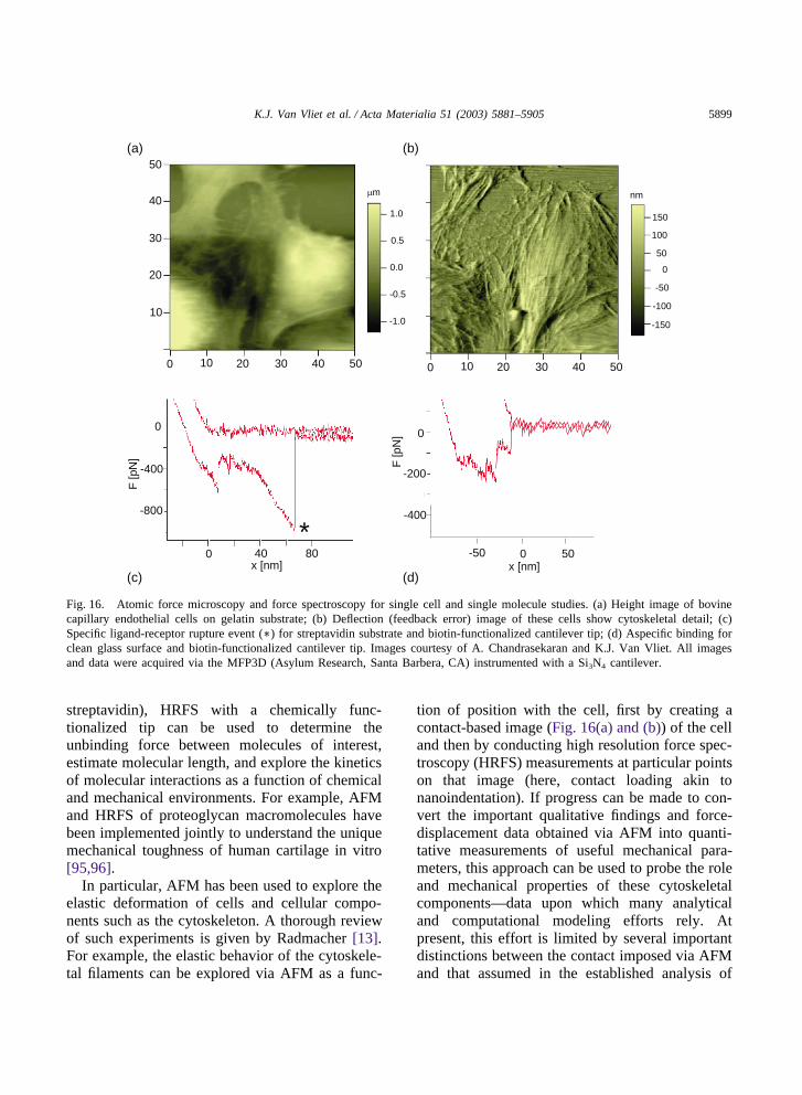
5899K.J. Van Vliet et al. / Acta Materialia 51 (2003) 5881–5905
1.0
0.5
0.0
-0.5
-1.0
150
100
50
0
-100
-150
-50
µm nm
(a) (b)
(c) (d)
F [p
N]
0 40 80x [nm]
0
-400
-800
0
-200
F [p
N]
0 50-50x [nm]
0 20 4010 30 50
10
20
30
40
50
0 20 4010 30 50
-400
*
Fig. 16. Atomic force microscopy and force spectroscopy for single cell and single molecule studies. (a) Height image of bovinecapillary endothelial cells on gelatin substrate; (b) Deflection (feedback error) image of these cells show cytoskeletal detail; (c)Specific ligand-receptor rupture event (∗) for streptavidin substrate and biotin-functionalized cantilever tip; (d) Aspecific binding forclean glass surface and biotin-functionalized cantilever tip. Images courtesy of A. Chandrasekaran and K.J. Van Vliet. All imagesand data were acquired via the MFP3D (Asylum Research, Santa Barbera, CA) instrumented with a Si3N4 cantilever.
streptavidin), HRFS with a chemically func-tionalized tip can be used to determine theunbinding force between molecules of interest,estimate molecular length, and explore the kineticsof molecular interactions as a function of chemicaland mechanical environments. For example, AFMand HRFS of proteoglycan macromolecules havebeen implemented jointly to understand the uniquemechanical toughness of human cartilage in vitro[95,96].
In particular, AFM has been used to explore theelastic deformation of cells and cellular compo-nents such as the cytoskeleton. A thorough reviewof such experiments is given by Radmacher [13].For example, the elastic behavior of the cytoskele-tal filaments can be explored via AFM as a func-
tion of position with the cell, first by creating acontact-based image (Fig. 16(a) and (b)) of the celland then by conducting high resolution force spec-troscopy (HRFS) measurements at particular pointson that image (here, contact loading akin tonanoindentation). If progress can be made to con-vert the important qualitative findings and force-displacement data obtained via AFM into quanti-tative measurements of useful mechanical para-meters, this approach can be used to probe the roleand mechanical properties of these cytoskeletalcomponents—data upon which many analyticaland computational modeling efforts rely. Atpresent, this effort is limited by several importantdistinctions between the contact imposed via AFMand that assumed in the established analysis of
5900 K.J. Van Vliet et al. / Acta Materialia 51 (2003) 5881–5905
nanoscale contact deformation (nanoindentation).First, due to the use of a laser for positional track-ing, the cantilever is inclined at an angle to thesurface (15°), such that the tip (a four-sided pyra-mid with an included apex angle of 35° and radiuson the order of 20 nm) does not approach normalto the cell surface. As such, the indentationgeometry is no longer self-similar, and loadingcontains a strong lateral force component(frictional stresses between the tip and the sample).Further, although the elastic theories of Hertz andSneddon [97] are often applied in the analysis ofthese data, both of these classic approaches areapplicable to normal contact and time-independent,linear elastic half spaces. These assumptions arenot valid for deformation of living cells adhered toa substrate, effectively acting as (layered) thinfilms on a substrate. There is significant effortunderway within the biophysics community toaddress these limitations, and increased interactionbetween the mechanical and materials engineeringcommunities who have made significant progressin the analysis and interpretation of contact-basedexperiments may lead to more rapid maturation ofthis important tool.
AFM can also be utilized to study single-mol-ecule biomechanics, including the unbinding ofantibody-antigen, ligand-receptor, and DNA-pro-tein pairs [98]. The experimental set up forunbinding of a ligand-receptor pair is similar tothat shown schematically in Fig. 15(a), except thatthe receptor molecules are adsorbed on a glass sur-face instead of expressed on a cell membrane [99].When the AFM tip contacts the chemically func-tionalized surface, binding occurs between theligand and receptor. Upon retraction of the cantil-ever, the bonds between the receptor and ligandmay break, resulting in the unbinding of the twomolecules. The corresponding unbinding force canbe calculated from the deflection of the cantileverat rupture. For example, using AFM, the ruptureforce and lifetime of the P-selectin and PSGL-1 (P-selectin glycoprotein ligand-1) complex were mea-sured. The AFM tip was functionalized withPSGL-1 by first adsorbing onto the tip a mono-clonal antibody specific for that protein (anti-PSGL-1 mAb PL2), and then blocking aspecificbinding of other species with another protein (1%
bovine serum albumin, or BSA). P-selectin wasreconstituted in a PEI (polyethylenimine) polymer-supported lipid bilayer. Binding between P-selectinand PSGL-1 was realized when the tip was broughtto contact with the bilayer for 3 s with a ~20 pNcompressive force. The cantilever was then retrac-ted at a displacement rate of 250 nm/s, and thenmaintained at a fixed deflection to apply a constantforce to the bond(s). The bond lifetime was meas-ured from the instant when the cantilever deflectionwas halted to the instant of bond(s) failure. It wasdemonstrated that binding between certain ligand-receptor pairs may have both catch bond and slipbond behavior. That is, increasing force first pro-longed and then shortened the lifetime of the recep-tor-ligand complex [99]. This dual response toforce provides a mechanism to regulate celladhesion under variable mechanical force.
There are several important issues in unbindingforce measurement. First, for single-molecule stud-ies, it is necessary to ensure that only one ligand-receptor pair is formed and ruptured, so that therupture force measured truly reflects the interactionbetween a single molecular pair. Second, the rup-ture force is usually dependent on the loading rate,especially for weak noncovalent bonds. Finally, thecantilever has on average a thermal energy of 0.5kBT, which implies that the smallest force that canbe accurately measured using commercially avail-able silicon nitride cantilever is on the order of ~10pN. For relatively weak interactions between biom-olecules, with an equivalent rupture force of �10pN, OT (Section 3.4) offers a viable alternative forforce measurement.
3.10. Biomembrane force probe
Finally, a technique related to MA butdeveloped for single molecule experiments is thebiomembrane force probe (BFP), whereby a cell orlipid vesicle is partially aspirated in a micropipetteand then serves as the force transducer. As shownin Fig. 17, ligand-coated beads are attached to thispressurized capsule and positioned to interact witha receptor of interest that is adhered to a nearbysubstrate. Deformation of the capsule is measuredoptically, and force maxima are controlled by thesurface tension (i.e., aspiration pressure) imposed

5901K.J. Van Vliet et al. / Acta Materialia 51 (2003) 5881–5905F
orce
[pN
]
10
0
-101 2 3
ligand-receptor rupture
retraction
approach
vesicletransducer
ligand-coated bead
micropipette
erythrocyte
contact
0
Time [s]
(a)
(b)
Fig. 17. Biomembrane force probe (BFP) for single moleculestudies. (a) The vesicle acts as a force transducer, relating theinteraction forces between a ligand-coated polystyrene bead andthe cell-surface receptors of an erythrocyte. (b) The ligand-receptor binding/unbinding forces measured depend on the rateof loading/unloading. This symmetric, low force response istypical of slow rates (10 pN/s). Images courtesy of E. Evans.
on this capsule. Force maxima approach 1000 pN,with resolution of 0.5 pN, and displacement resol-ution is on the order of 500 nm. An interestingexample of this approach is shown in Fig. 17(a),where erythrocyte-ECM adhesion was probeddirectly by using the erythrocyte as the force trans-ducer [9].
This BFP method has also been utilized to illus-trate the loading-rate dependence of the ligand-receptor unbinding force (Fig. 17b) [100]. In parti-cular, using BFP, the bond strength of the streptav-idin (or avidin)-biotin complex was found toincrease from about 5 to 170 pN when loading rateincreased over six orders of magnitude [101], asshown in Fig. 18. Therefore, binding between twoproteins may appear strong or weak depending on
100
104
106
102
Loading rate [pN s ]-1
Force [pN]
200
300
Fre
quen
cy
0.050
0.025
(a)
(b)200
150
100
50
010-2 100 102 104 106
AFM
streptavidinavidin
Loading rate [pN s ]-1
For
ce [p
N]
Fig. 18. Biotin–streptavidin bond strengths measured via BFP.(a) Force histograms from BFP experiments on single biotin–streptavidin bonds demonstrate shift in peak location andincrease in width with increase in loading rate. Gaussian fitsused to determine the most frequent rupture force or bondstrength are shown. (b) Dynamic strength spectra for biotin–streptavidin (circles) and biotin-avidin (triangles) bonds. Con-sistent with the high-strength regime is the biotin–streptavidinstrength measured recently by atomic-force microscopy (AFM).
loading rate. In this experiment, amino silanegroups were covalently bound to glass microbeads.Amine-reactive polyethylene glycol (PEG) poly-mers with and without biotin end groups werecovalently linked to the silanized surfaces, and thebiotinylated beads were exposed to excess(strept)avidin and then washed. An erythrocytecovalently linked with PEG-biotin polymers wasjoined to the avidinated microbead to construct theprobe, similar to Fig. 17(a). Although the BFP
5902 K.J. Van Vliet et al. / Acta Materialia 51 (2003) 5881–5905
method is quite specialized and does not provideforce or displacement capabilities distinct fromthose achievable via the other techniques discussedherein, BFP remains an interesting example of howcell mechanics may be exploited in instrumentdesign for single molecule biomechanics studies.
4. Concluding remarks
In this review, we have outlined an impressivearray of experimental tools that can be utilized tofurther our understanding of whether and how themechanical environment and mechanical behaviorof a cell affects its biological function. Despite theapparent simplicity of the force-displacementrelationships that govern these techniques, thesophistication of our experimental tools farexceeds our current analytical and computationalunderstanding. Rigorous interpretations of howforce, stress and energy can be imposed and meas-ured via these approaches will enable more accur-ate assessment of current results and also morelucid comparison of results among the differentexperimental tools. Certainly, the coupled chemi-cal interactions and the inherent time dependenceof molecular and cellular processes present chal-lenging opportunities for further research (see, e.g.,Ref. [102]). Further, in order to maximize theengineering potential of these capabilities, it isessential to recognize how biological systems areintrinsically different from synthetic material sys-tems, as well as which outstanding questions indevelopmental and pathological biology can beaddressed via quantification of mechanicalresponses.
For example, it is interesting to note that themechanical response of individual cells and cellmembranes is known to have a direct connection tocertain pathologies. Recent experiments performedusing OT [60] and MA [103] have shown thatinfestation of human erythrocytes with the malariaparasite plasmodium falciparum can cause up to aten fold increase in the cell membrane shear modu-lus as the disease state progresses. The interactionof parasite proteins with the cell cytoplasm, actincortex and other membrane components mediatesstructural and functional changes of the erythrocyte
which, in turn, are reflected in the mechanics ofdeformation of the cell [104]. How such connec-tions can be used to probe the specific mechanismsby which different diseases progress and the meansby which they can be diagnosed and treated effec-tively remain topics of considerable opportunityand challenge in which the biomechanics toolsconsidered in this review article will inevitablyplay a critical role. Our collective and sustainedinteraction with experts from other establishedresearch communities including cell and molecularbiology and biophysics can serve to clarify themechanical concepts relevant to disease and devel-opment, and to increase our own understanding ofhow the fundamental mechanics and physics ofmaterial systems are affected by environmentalinteractions.
Acknowledgements
The authors gratefully acknowledge those whocontributed images and helpful discussion on spe-cific techniques, especially Y.-L. Wang, J. Guck,J. Kas, F. Guilak, J. Tan, C. Chen, E. Evans, C.C.Scott, K. Athanasiou and A. Gouldstone. KJVVthanks M.A. Moses at Children’s Hospital Boston,Harvard Medical School, and the Department ofMaterials Science and Engineering at MIT for fin-ancial support. SS acknowledges support for thepreparation of this paper from the US ArmyResearch Office and from the Singapore-MITAlliance. GB acknowledges the support of the USArmy Research Office (grant No. 44062-EG).
References
[1] Feeback DL, Clarke MSF. Improved unidirectional cell-stretching device. In: Book Improved unidirectional cell-stretching device.http://www.nasatech.com/Briefs/Aug00/MSC22834.html; 2000.
[2] Pelham RJ, Wang Y-L. Cell locomotion and focaladhesions are regulated by substrate flexibility. Proceed-ings of the National Academy of Science USA1997;94:13661–5.
[3] Beningo KA, Wang Y-L. Flexible substrata for the detec-tion of cellular traction forces. Trends in Cell Biology2002;12:79–84.
5903K.J. Van Vliet et al. / Acta Materialia 51 (2003) 5881–5905
[4] Tan JL, Tien J, Pirone DM, Gray DS, Bhadriraju K, ChenCS. Cells lying on a bed of microneedles: An approachto isolate mechanical force. Proceedings of the NationalAcademy of Science 2003;100:1484–9.
[5] Fabry B, Butler JP, Navajas D, Tschumperlin DJ,Laporte JD, Maksym GN, Fredberg JJ. Mechanicalproperties of cultured human airway smooth muscle cellsfrom 0.05 to 4 Hz. J Appl Physiol 2000;89.
[6] Puig-de-Morales M, Grabulosa M, Alcaraz J, Mullol J,Maksym GN, Fredberg JJ, Navajas D. Measurement ofcell microrheology by magnetic twisting cytometry withfrequency domain demodulation. Journal of AppliedPhysiology 2001;91:1152–9.
[7] Maksym GN, Fabry B, Butler JP, Navajas D, Tschum-perlin DJ, Laporte JD, Fredberg JJ. Mechanical proper-ties of cultured human airway smooth muscle cells from0.05 to 0.4 Hz. Journal of Applied Physiology2000;89:1619–32.
[8] Athanasiou KA, Thoma BS, Lanctot DR, Shin D, Agra-wal CM, LeBaron RG. Development of the cytodetach-ment technique to quantify mechanical adhesiveness ofthe single cell. Biomaterials 1999;20:2405–15.
[9] Yeung A, Evans E. Cortical shell-liquid core model forpassive flow of liquid-like spherical cells into micropip-ets. Biophysical Journal 1989;56:139–49.
[10] Evans E, Yeung A. Apparent viscosity and cortical ten-sion of blood granulocytes determined by micropipetaspiration. Biophysical Journal 1989;56:151–60.
[11] Ananthakrishnan R, Moon TJ, Cunningham CC, GuckKJJ. Optical deformability of soft biological dielectrics.Physical Review Letters 2000;84:5451–4.
[12] Wu HW, Kuhn T, Moy VT. Mechanical properties ofl929 cells measured by atomic force microscopy: Effectsof anticytoskeletal drugs and membrane crosslinking.Scanning 1998;20:389–97.
[13] Radmacher M. Measuring the elastic properties of livingcells by the atomic force microscope. Atomic ForceMicroscopy in Cell Biology 2002;68:67–90.
[14] Czajkowsky DM, Shao ZF. Supported lipid bilayers aseffective substrates for atomic force microscopy. AtomicForce Microscopy in Cell Biology 2002;68:231–41.
[15] Goldmann WH. Mechanical manipulation of animalcells: cell indentation. Biotechnology Letters2000;22:431–5.
[16] Rotsch C, Braet F, Wisse E, Radmacher M. AFM imag-ing and elasticity measurements on living rat liver macro-phages. Cell Biol Int 1997;21:685–96.
[17] Rotsch C, Radmacher M. Drug induced changes in cytos-keletal structure and mechanics in fibroblasts-An atomicforce microscopy study. Biophysical Journal2000;78:520–35.
[18] Benoit M. Cell adhesion measured by force spectroscopyon living cells. Atomic Force Microscopy in Cell Biology2002;68:91–114.
[19] Chen AL, Moy VT. Single-molecule force measure-ments. Atomic Force Microscopy in Cell Biology2002;68:301–9.
[20] Felder S, Elson EL. Mechanics of fibroblast locomotion:Quantitative analysis of forces and motions at the leadinglamellas of fibroblasts. Journal of Cell Biology1990;111:2513–26.
[21] Peterson NO, McConnaughey WB, Elson EL. Depen-dence of locally measured cellular deformability on pos-ition in the cell, temperature and cytochalasin B. Pro-ceedings of the National Academy of Sciences USA1982;79:5327–31.
[22] Sleep J, Wilson D, Simmons R, Gratzer W. Elasticityof the red cell membrane and its relation to hemolyticdisorders: An optical tweezers study. Biophysical Journal1999;77:3085–95.
[23] Bausch AR, Ziemann F, Boubitch AA, Jacobson K,Sackmann E. Local measurements of viscoelastic para-meters of adherent cell surfaces by magnetic bead rheo-metry. Biophysical Journal 1998;75:2038–49.
[24] Crick FHC, Hughes AFW. The physical properties of thecytoplasm. a study by the means of the magnetic particlemethod. Experimental Cell Research 1965;1:37–80.
[25] Bausch AR, Moller W, Sackmann E. Measurement oflocal viscoelasticity and forces in living cells by mag-netic tweezers. Biophysical Journal 1999;76:573–9.
[26] Alenghat FJ, Fabry B, Tsai KY, Goldmann WH, IngberDE. Analysis of cell mechanics in single vinculin-deficient cells using a magnetic tweezer. Biochemicaland Biophysical Research Communications2000;277:93–9.
[27] Brown TD. Techniques for mechanical stimulation ofcells in vitro: A review. Journal of Biomechanics2000;33:3–14.
[28] Pioletti DP, Muller J, Rakotomanana LR, Corbeil J, WildE. Effect of micromechanical stimulations on osteoblasts:development of a device simulating the mechanical situ-ation at the bone-implant interface. Journal of Biomech-anics 2003;36:131–5.
[29] Lee AA, Delhaas T, Waldman LK, MacKenna DA, Vil-larreal FJ, McCulloch AD. An equibiaxial strain systemfor cultured cells. American Journal of Physiology-CellPhysiology 1996;40:C1400–C8.
[30] Zhu C, Bao G, Wang N. Cell mechanics: Mechanicalresponse, cell adhesion, and molecular deformation.Annual Review of Biomedical Engineering2000;2:189–226.
[31] Jones DB, Nolte H, Scholubbers GE, Turner J, Veltel D.Biochemical signal transduction of mechanical strain inoseoblast-like cells. Biomaterials 1991;12:101–10.
[32] Dunn A, Moses MA, Van Vliet KJ. Effects of radial,cyclic strain on enzyme activity in endothelial cells 2003(in preparation).
[33] Wang HC, Ip W, Boissy R, Grood ES. Cell orientationresponse to cyclically deformed substrates: Experimentalvalidation of a cell model. Journal of Biomechanics1543;1995:28.
[34] Pfister BJ, Weihs TP, Betenbaugh M, Bao G. An in vitrouniaxial stretch model for axonal injury. Ann BiomedEng 2003;31:589–98.

5904 K.J. Van Vliet et al. / Acta Materialia 51 (2003) 5881–5905
[35] Cohen Y, Ramon O, Kopelman IJ, Mizrahi S. Journal ofPolymer Science B 1992;30:1055-1067.
[36] Lo C-M, Wang H-B, Dembo M, Wang Y-L. Cell move-ment is guided by the rigidity of the substrates. BiophysJ 2000;79:144–52.
[37] Lo C-M, Wang H-B, Dembo M, Wang YL.http://ylwang.umassmed.edu/video/guidance.htm, City2000.
[38] Wang N, Ostuni E, Whitesides GM, Ingber DE.Micropatterning tractional forces in living cells. CellMotility and the Cytoskeleton 2002;52:97–106.
[39] Munevar S, Dembo M, Wang Y-L. Traction forcemicroscopy of normal and transformed fibroblasts.Biophys J 2001;80:1744–57.
[40] Butler JP, Wang N, Ingber DE. Mechanotransductionacross the cell surface and through the cytoskeleton.Science 1993;260:124–1127.
[41] Fabry B, Maksym GN, Hubmayr RD, Butler JP, Fred-berg JJ. Implications of heterogeneous bead behavior oncell mechanical properties measured with magnetic twist-ing cytometry. Journal of Magnetism and MagneticMaterials 1999;194:120–5.
[42] Dike LE, Chen CS, Mrksich M, Tien J, Whitesides GM,Ingber DE. Geometric control of switching betweengrowth, apoptosis, and differentiation during angiogen-esis using micropattened substrates. In vitro Cell DevBiol 1999;35:441–8.
[43] Parker KK, Brock AL, Brangwynne C, Mannix RJ,Wang N, Ostuni E, Geisse NA, Adams JC, WhitesidesGM, Ingber DE. Directional control of lamellipodiaextension by constraining cell shape and orienting celltractional forces. FASEB 2002;16:1195–204.
[44] Singhvi R, Kumar A, Lopez GP, Stephanopoulos GN,Wang DIC, Whitesides GM, Ingber DE. Engineering cellshape and function. Science 1994;264:696–9.
[45] Xia Y, Whitesides GM. Soft lithography. Ann Rev MaterSci 1998;28:153–84.
[46] Hochmuth RM. Micropipette aspiration of living cells.Journal of Biomechanics 2000;33:15–22.
[47] Shao J-Y. Measuring piconewton forces and its appli-cation in cellular and molecular biomechanics. Advancesin Biomechanics 2001:47-51.
[48] Hochmuth RM, Ting-Beall HB, Beaty BB, Needham D,Tran-Son-Tay R. Viscosity of passive human neutrophilsundergoing small deformations. Biophysical Journal1993;64:1596–601.
[49] Sato J, Levesque MJ, Nerem RM. Micropipette aspir-ation of cultured bovine aortic endothelial cells exposedto shear stress. Arteriosclerosis 1987;7:276–86.
[50] Jones WR, Ting-Beall HP, Lee GM, Kelley SS, Hoch-muth RM, Guilak F. Alterations in the Young’s modulusand volumetric properties of chondrocytes isolated fromnormal and osteoarthritic human cartilage. Journal ofBiomechanics 1999;32:119–27.
[51] Secomb TW. Red-blood-cell mechanics and capillaryblood rheology. Cell Biophysics 1991;18:231–51.
[52] Secomb TW, Hsu R. Red blood cell mechanics and func-
tional capillary density. International Journal of Microcir-culation-Clinical and Experimental 1995;15:250–4.
[53] Wu JZ, Herzog W, Epstein M. Modelling of location-and time-dependent deformation of chondrocytes duringcartilage loading. Journal of Biomechanics1999;32:563–72.
[54] Wu JZ, Herzog W. Finite element simulation of location-and time-dependent mechanical behavior of chondro-cytes in unconfined compression tests. Annals of Biom-edical Engineering 2000;28:318–30.
[55] Guilak F, Mow VC. The mechanical environment of thechondrocyte: a biphasic finite element model of cell-matrix interactions in articular cartilage. Journal ofBiomechanics 2000;33:1663–73.
[56] Haider MA, Guilak F. An axisymmetric boundary inte-gral model for incompressible linear viscoelasticity:Application to the micropipette aspiration contact prob-lem. Journal of Biomechanical Engineering-Transactionsof the ASME 2000;122:236–44.
[57] Haider MA, Guilak F. An axisymmetric boundary inte-gral model for assessing elastic cell properties in themicropipette aspiration contact problem. Journal ofBiomechanical Engineering-Transactions of the ASME2002;124:586–95.
[58] Boey SK, Boal DH, Discher DE. Biophysical Journal1998;75:1573-1583.
[59] Discher DE, Boad DH, Boey SK. Biophysical Journal1998;75:1584-1597.
[60] Lim CT, Lee YS, Tan K, Dao M, Suresh S. NationalUniversity of Singapore and Massachusetts Institute ofTechnology. National University of Singapore and Mas-sachusetts Institute of Technology; 2003 (unpulbishedresults).
[61] Ashkin A. Optical Letters 1986;11:288.[62] Ashkin A, Dziedzic JM. Optical trapping and manipu-
lation of viruses and bacteria. Science 1987;235:1517–20.
[63] Smith SB, Cui Y, Bustamante C. An optical-trap forcetransducer that operates by direct measurement of lightmomentum. Methods in Enzymology 2002;79:144–52.
[64] Williams MC. Optical tweezers: Measuring piconewtonforces. In: Schwille P, editor. Single Molecule Tech-niques. Biophysics Textbook Online; 2002.
[65] Gittes F, Schmidt C. In: L. Wilson, M. Sheetz, P. Matsu-daira (Eds.), Laser Tweezers in Cell Biology. San Diego:Academic Press; 1998.
[66] Chew KT, Lim CT, Sow CH, Dao M, Suresh S. Largedeformation of human red blood cell by direct stretchusing optical tweezers. 2003 (in preparation).
[67] Dao M, Lim CT, Suresh S. Mechanics of the human redblood cell deformed by optical tweezers. J Mech PhysSolids 2003, (in press).
[68] Henon S, Lenormand G, Richert A, Gallet F. Biophys J1999;76:1145-1151.
[69] Sleep J, Wilson D, Simmons R, Gratzer W. Biophys J1999;77:3085-3095.
5905K.J. Van Vliet et al. / Acta Materialia 51 (2003) 5881–5905
[70] Lenormand G, Henon S, Richert A, Gallet F. Biophys J2001;81:43-56.
[71] Prentiss H. Unpublished discussion of four optical trapsto manipulate cells. http://atomsun.harvard.edu/; 2003.
[72] Curtis JE, Koss BA, Grier DG. Dynamic holographicoptical tweezers. Opt Comm 2002;207:169–75.
[73] Mehta AD, Rief M, Spudich JA, Smith DA, SimmonsRM. Single-molecule biomechanics with opticalmethods. Science 1999;283:1689–95.
[74] Svoboda K, Block SM, Asbury CL, Shaevitz JW, LangMJ. Force and velocity measured for single kinesin mol-ecules. Cell 1994;77:773–84.
[75] Guck J, Chiang JA, Kas J. The optical stretcher: A noveltool to characterize the cytoskeleton. Molecular Biologyof the Cell 1998;9:609.
[76] Guck J, Ananthakrishnan R, Moon TJ, Cunningham CC,Kas J. Optical deformability of soft biological dielectrics.Physical Review Letters 2000;84:5451–4.
[77] Guck J, Ananthakrishnan R, Moon TJ, Cunningham CC,Kas J. Optical deformability of cells. Biophysical Jour-nal 2000;78:2170Pos.
[78] Guck J, Ananthakrishnan R, Mahmood H, Moon TJ,Cunningham CC, Kas J. The optical stretcher: A novellaser tool to micromanipulate cells. Biophysical Journal2001;81:767–84.
[79] Guck J, Ananthakrishnan R, Mahmood H, Moon TJ,Cunningham CC, Hallworth R, Kas J. The opticalstretcher-A novel laser tool to micromanipulate cells.Biophysical Journal 2001;80:1138.
[80] Guck J, Ananthakrishnan R, Cunningham CC, Kas J.Stretching biological cells with light. Journal of Physics-Condensed Matter 2002;14:4843–56.
[81] Kas J, Guck J, Chiang JA. The optical stretcher - A noveltool to manipulate cells. Biophysical Journal1999;76:A276–A.
[82] Moore SA, Guck J, Ananthakrishnan R, CunninghamCC, Kas JA. The reverse progression of cancer in HL-60cells as monitored by optical deformability. BiophysicalJournal 1683;2002:82.
[83] Smith SB, Finzi L, Bustamante C. Direct mechanicalmeasurements of the elasticity of single DNA moleculesby using magnetic beads. Science 1992;258:1122–6.
[84] Strick TR, Allemand JF, Bensimon D, Bensimon A, Cro-quette V. The elasticity of a single supercoiled DNA mol-ecule. Science 1996;271:1835–7.
[85] Gosse C, Croquette V. Magnetic tweezers: Micromanipu-lation and force measurement at the molecular level.Biophysical Journal 2002;82:3314–29.
[86] Hwang WC, Waugh RE. Energy of dissociation of lipidbilayer from the membrane skeleton of red blood cells.Biophysical Journal 1997;72:2669–78.
[87] Ishijima A, Doi T, Sakurada K, Yanagida T. Sub-piconewton force fluctuations of actomyosin in vitro.Nature 1991;352:301–6.
[88] Binnig G, Quate CF, Gerber C. Atomic force micro-scope. Physical Review Letters 1986;56:930–4.
[89] Barbee KA. Changes in surface topography in endo-thelial monolayers with time at confluence: Influence onsubcellular shear stress distribution due to flow. Bio-chemistry and Cell Biology-Biochimie Et Biologie Cellu-laire 1995;73:501–5.
[90] Charras G, Lehenkari P, Horton M. Biotechnologicalapplications of atomic force microscopy. Atomic ForceMicroscopy in Cell Biology 2002;68:171–91.
[91] Kumar S, Hoh JH. Probing the machinery of intracellulartrafficking with the atomic force microscope. Traffic2001;2:746–56.
[92] Lesniewska E, Milhiet PE, Giocondi MC, Le GrimellecC. Atomic force microscope imaging of cells and mem-branes. Atomic Force Microscopy in Cell Biology2002;68:51–65.
[93] Domke J, Dannohl S, Parak WJ, Muller O, Aicher WK,Radmacher M. Substrate dependent differencs in mor-phology and elasticity of living osteoblasts investigatedby atomic force microscopy. Colloid Surfaces B2000;19:367–73.
[94] Hinterdorfer P. Molecular recognition studies using theatomic force microscope. Atomic Force Microscopy inCell Biology 2002;68:115–39.
[95] Ng L, Grodzinsky A, Plaas A, Sandy J, Ortiz C. J StructBio (in press).
[96] Seog J, Dean D, Plaas A, Wong-Palms S, Grodzinsky A,Ortiz C. Macromolecules 2002;35:5601-5615.
[97] Sneddon IN. The relation between load and penetrationin the axisymmetric boussinesq problem for a punch ofarbitrary profile. International Journal of EngineeringScience 1965;3:47–57.
[98] Willemsen OH, Snel MM, Cambi A, Greve J, De GroothBG, Figdor CG. Biomolecular interactions measured byatomic force microscopy. Biophys J 2000;79:3267–81.
[99] Marshall BT, Long M, Piper JW, Yago T, McEver RP,Zhu C. Direct observation of catch bonds. Nature 2003.
[100] Evans E. Probing the relation between force, lifetime andchemistry in single molecular bonds. Annual Review ofBiophysics and Biomolecular Structure 2001;30:105–28.
[101] Merkel R, Nassoy P, Leung A, Ritchie K, Evans E.Energy landscapes of receptor-ligand bonds exploredwith dynamic force spectroscopy. Nature 1999;397:50–3.
[102] G. Bao, S. Suresh, 2003, Cell and molecular mechanicsof biological materials. MIT Nature Materials,2003;2:715–25.
[103] Glenister FK, Coppel RL, Cowman AF, Mohandas N,Cooke BM. Blood 2002;99:1060-1063.
[104] Cooke BM, Mohandas N, Coppel RL. Adv Parasitology2001;50:1-86.
[105] Freyman TM, Yannas IV, Yokoo R, Gibson LJ. Fibro-blast contraction of a collagen-GAG matrix. Biomaterials2001;22:2883–91.
[106] Guck J. Private communication with K.J. Van Vliet,2003.