Embed Size (px)
Citation preview
THE BIODEX RTM REHABILITATION TREADMILL OPERATION MANUALFor RTM Model 400 with Numeric Display(#945-275)
and RTM Model 500 with Graphic Display(#945-285)
NOTE: The following symbol on your Biodex RTM Treadmill corresponds to the RTMOperation Manual:
Symbol Signification: Attention, se référer à la notice
Symbol Meaning: Attention, consult accompanying documents
CAUTION: Federal law restricts this device to sale by or on the order of a medical practitioner. When prescribed for therapeutic purpose, a physician should clearly define theparameters of use (i.e., total work, maximum heart rate, etc.) to reduce the risk of patientinjury.
0413
BIODEXBiodex Medical Systems, Inc.
20 Ramsay Road, Shirley, New York, 11967-0702 Tel: 800-224-6339 (In NY Call 631-924-9000), Fax: 631-924-9338
Email: [email protected], www.biodex.com
1. Introduction..................................................................................3
2. Clinical Considerations ..............................................................4
3. Using the RTM Model 400 Numeric Display/Control Panel5-12• Power Up• RTM Model 400 Numeric Display Control Keys and Functions
• Basic Operation of the RTM Model 400 with Numeric Display
• Changing Measurement Units• Zero Balance Adjustment• Using the RS-232 Computer Interface Port
4. Using the RTM Model 500 Graphics Display/Control Panel..........................................................13-26
• Power UP• RTM Model 500 Graphic Display Control Keysand Functions
• Standard Operation of the RTM Model 500 with Graphics Display
• The Performance/Control Screen• Exercise Setup Screen• System Utilities• Using the Heart Monitoring Feature (Optional)• Programmable Options
5. Resistive Gait Training (Optional for RTM Model 500 with Graphic Display)..........................................................27-28
6. Maintenance........................................................................29-32
7. Troubleshooting....................................................................33-34
8. System Diagnostics..............................................................35-37
9. Calibration Verification........................................................38-39
10. Installation of Optional Arm Restsand Elevation Rockers ........................................................40-41
• Installing the Arm Rest Pads• Installing the Elevation Rockers
11. Replacement Parts List..............................................................42
12. Specifications ............................................................................43
13. Assembly Diagrams and Schematic ................................44-47
TABLE OF CONTENTS
TABLE OF CONTENTS — 2 —
Designed specifically for rehabilitation purposes, the Biodex Rehabilitation
Treadmill (RTM) provides unparalleled speed control and durability, incline and
decline in both forward and reverse directions, digital feedback, a neat, trim, low
profile, a choice of handrail configurations, plus optional heart rate monitoring.
A choice of Numeric display (RTM Model 400) or Graphic display (RTM Model
500) allows the user to choose between a simple, no-nonsense approach that gets
the patient up and moving in a matter of seconds, or full programming capabili-
ty that allows for use of user-defined or factory installed exercise protocols at
any of five selected intensity levels. With this choice of control panel displays,
the Biodex RTM Treadmill offers the flexibility needed to suit any facility
Both the RTM Model 400 and 500 allow patients to walk, jog and run, with or
without grade (0 to 15% incline/decline,) as they exercise every muscle targeted
in their personalized rehabilitation program. Multiple handrail configurations
allow clinicians to set up for various applications including physical
therapy/sports medicine, cardiac/pulmonary rehabilitation, geriatric and pedi-
atric conditioning, and use with neurological patients.
Additionally, 4Q Pulse Width Modulation motor control, the same motor control
that helped make the Biodex Dynamometer the worldwide choice for extremity
testing and rehabilitation, provides more consistent speed control than either AC
or DC treadmill models can ever hope to attain. With track speeds of 0-8 mph
(12.0 Km/h) in forward and 0-3 mph (4.8 Km/h) in reverse, a zero starting speed,
the ability to change speeds in .1-mph (.2-Km/h) increments, easy to read displays
and touch-key operation, PWM motor control and a choice of handrail configura-
tions, the RTM treadmill is among the safest and most versatile available today.
The Biodex RTM Model 400 and 500 treadmills come fully assembled. There is
only one mechanical adjustment to be made and that is simply tilting the display
panel to the most comfortable viewing angle for the patient. Once this is done,
all operation is electronically controlled.
In addition to all the standard features noted above, RTM Model 500 with
Graphic Display options include -3 to 12% incline/decline (ideal for work with
back and posture patients) and Resistive Gait training capability that allows
patients to simulate pushing or pulling a specified load while walking, jogging
or even running.
NOTE: This operations manual is designed for use with both the RTM Model 400 and500. Chapter 3 covers specific use of the RTM Model 400 with Numeric Display.Chapter 4 covers specific use of the RTM Model 500 with Graphic Display. All otherchapters, except where noted, apply to both models.
INTRODUCTION
— 3 — INTRODUCTION

1 All patients should consult a physician before beginning any rehabilitation program.
Tous les patients doivent voir leur médecin responsable avant d'entreprendre laséance de rééducation.
2 Instruct patient on proper use and all treadmill safety features before beginningexercise.
Expliquer au patient la bonne utilisation des systémes de sécurité du tapis avantde démarrer la séance.
3 Always attach the Safety Lanyard to the patient's clothing before allowing treadmill exercise to begin.
Connector toujours la sangle de sécurité aux vêtements du patient avant que le patient necommence à travailler.
4 Ensure patient has stretched and warmed-up prior to starting treadmill exercise.
Vérifier que la patient s'est échauffé et a fait des étirements avant de commencer l'entraînement sur le tapis.
5 Do not allow any patient to exercise unattended on the treadmill. Never leave thetreadmill running while unattended.
Ne pas laisser le patient seul sur le tapis pendant la séance. Ne jamais laisser letapis tourner sans patient et sans surveillance.
6 Periodically monitor the heart rate of any patient that is exercising on the treadmill.
Surveiller de temps à autre la fréquence cardiaque du patient pendant la séance.
7 Begin all treadmill exercise at slow pace, increasing speed gradually to patienttolerance or exercise goal. Always inform the patient immediately prior toincreasing or decreasing treadmill speed or elevation.
Démarrer les protocloes à une vitesse lente et augmenter progressivement lavitesse en fonction de la tolérance du patient et des objectifs de la séance.Signaler avant de l'appliquer tonte augmentation ou diminution de vitesse oud'inclinaison.
8 If reversing treadmill direction, bring the treadmill to a complete stop and informpatient that the treadmill will begin moving in the opposite direction.
Avant de changer la direction de déplacement du tapis, arrêter le tapis complétement et expliquer au patient que le tapis va démarrer dans le sens opposé.
9 Immediately discontinue exercise if patient feels faint, dizzy or short of breath.
Arrêter la séance immédiatement en cas de dyspnée, d'étourdissements ou d'autressignes de malaise.
10 Never allow anyone to step onto the treadmill while the treadbelt is in motion.Always stop the treadmill prior to allowing the patient to step up onto the treadbelt.
Ne jamais faire monter personne sur le tapis pendant que le tapis est en marche.Arrêter toujours le tapis avant que le patient ne s'y positionne.
11 Instruct patients to use the handrails when first learning to walk on the treadmill.
Donner la consigne au patient d'utiliser les barres horizontales lors de sa premiéreséance sur le tapis.
CLINICAL CONSIDERATIONS
CLINICAL CONSIDERATIONS — 4 —
!
!
The Biodex RTM 400 with Numeric Display provides a simple-to-use, easy-to-read,
no-nonsense approach to treadmill exercise. Real time readings are displayed for
Time, Distance, Calories and MET values. At the touch of a key, users can select
speed, elevation and belt direction, or set an end time for exercise duration.
POWER-UPTo provide power to the treadmill, ensure the power plug is connected to an
appropriate socket. Press the ON/OFF switch, located on the base of the tread-
mill in the left corner at the front end, to the “l” (ON) position. All display win-
dows should illuminate to indicate that power to the treadmill is ON and the
display is active.
RTM MODEL 400 NUMERIC DISPLAY PANEL CONTROL KEYS ANDFUNCTIONS (See Figure 1.)<Start>: Pressing the <Start> key with the treadmill ON activates the treadbelt
and clock, and commands the system to begin gathering data with commence-
ment of the exercise session. Initial starting speed for treadbelt movement in
either forward or reverse direction is 0 mph. Speed can be increased or
decreased in .1 mph increments.
<Stop>: Press <Stop> at any time to ramp the treadmill to a complete stop. All
data on the screen will be retained. At this point, you can press <Clear Display>
to end the session and immediately clear all data, or press <Stop> to end the ses-
sion but retain all data for 90 seconds before it is cleared.
<Speed>: Use the <Speed> <+> and <-> control keys on the left side of the display
to adjust the speed to the desired level. The speed will immediately respond to
your input so be sure to inform the patient that the treadbelt will begin to acceler-
ate or decelerate. Gathering of data begins immediately at the point from which
the treadmill begins to move in either forward or reverse direction.
<Elevation>: If incline or decline is desired, use the <Elevation> <+> and <->
control keys in the middle of the display panel to set the appropriate grade.
Incline and decline can range from 0 to 15% grade. Note that there is a slight
delay between movement of the Elevation display bar and the actual movement
of the treadmill.
<Belt Direction>: Treadmill belt direction is selected via the <Forward> or
<Reverse> keys. Belt direction can be changed only when speed is set to 0 speed.
If you try to change direction while the treadbelt is moving, the system will
automatically ramp down to 0 speed and wait for further input. For reverse
direction, a minus (-) sign precedes the speed value. An orange LED denotes the
selected belt direction.
400 NUMERIC DISPLAY/CONTROL PANEL
— 5 —400 NUMERIC DISPLAY/CONTROL

<Select Display>: The <Select Display> key, located at the center of the control
panel’s top section, is used to determine which parameter will be displayed as data
is acquired. All parameters are listed to the left of the <Select Display> key. An
LED denotes the currently active parameter. Once you press the <Start> key, the
display will scroll through the parameters, showing each for a 15-second interval
before moving onto the next. An LED, to the left of the currently displayed para-
meter, denotes the active selection. To constantly display a single parameter, use
the <Select Display> to rotate through the parameter list and make your selection
after the treadbelt has begun to move. For all parameters, immediate biofeedback is
provided in numeric format for the selected parameter, as described below:
• Time: Cumulative time in minutes/seconds from the point at which the tread-
belt begins to move in either direction.
• Distance (Miles/Kilometers): The distance covered in miles or kilometers from
the beginning to the end of the current exercise session.
• Calories: Total calories burned by the user during the current exercise session.
This value is cumulative.
• METs: The METs value reflects the resting rate of Oxygen consumption with
one MET equal to the Oxygen consumption of a seated individual at rest. Thus,
a seated individual in a resting state is consuming 1 MET. A seated individual
exercising at a rate of 2 METs is consuming twice the Oxygen of a seated, resting
individual. A person exercising at 10 METs is consuming ten times the Oxygen
of a seated, resting individual. To compute the METs of a person actively exercis-
ing on the RTM Model 400 Treadmill, the system uses standard calculations
based on American College of Sports Medicine Guidelines for Testing and
Exercise. On the RTM Model 400 Treadmill, the MET’s value is always displayed
in real-time for current speed.
<Clear Display>: Pressing this key immediately clears the system of all acquired
data and resets all display parameters to their default settings.
<Set Weight>: Press the <Set Weight> key to display the default weight setting of
150 pounds. To alter the default setting, use the <+> or <-> keys on the right
side of the display. The set weight parameter is used to calculate Calories.
<Set Time>: Press the <Set Time> key to display the default time setting of 15:00.
To alter the default setting, use the <+> or <-> keys on the right side of the dis-
play. Use the Set Time function to provide an end time for exercise duration.
Once a time has been entered, the clock will begin counting down from the
point the treadbelt begins to move.
400 NUMERIC DISPLAY/CONTROL PANEL
400 NUMERIC DISPLAY/CONTROL PANEL— 6 —

Safety Lanyard and Safety Stop: Disconnecting the Safety Lanyard (to the left side
of Display/Control Panel) or pressing the red Safety Stop (to the right side of
Display/Control Panel on the upper frame) at any time will cause the treadbelt
to immediately ramp down to a full stop and reset to 0.0 mph. The Display will
read <Safe> and the treadbelt will not restart until the lanyard is once again in
position or <Start> is pressed following use of the Safety Stop. Display data is
not lost in either case. Data accumulation will resume once the lanyard is recon-
nected or <Start> has been pressed. To fully abort an exercise session after press-
ing the Safety Stop, press <Clear Display>.
Figure 1. The RTM Model 400 Numeric Display/Control Panel.
400 NUMERIC DISPLAY/CONTROL PANEL
— 7 —400 NUMERIC DISPLAY/CONTROL

BASIC OPERATION OF THE RTM MODEL 400 WITH NUMERIC DISPLAY
At this point, the RTM Model 400 should be ready for operation. To get the
treadmill up and running simply follow the procedure below.
1. Ensure that the <ON/OFF< switch, located on the left side of the front
base, is set to the “l” (ON) position. The Numeric Display should be illumi-
nated, indicating that power to the treadmill is ON.
2. If desired, use the <Set Weight> keys to enter a weight to be used for calo-
rie calculation. Default value is 150 pounds (68 kgs.).
3. If desired, use the <Set Time> keys to predetermine exercise duration.
4. Position the patient on the treadmill and explain the exercise routine.
5. Tilt the display panel for patient viewing comfort.
6. Attach the Safety Lanyard at the left corner of the top cross bar which sup-
ports the Display panel. The round end of the lanyard attaches to the unit
via a Velcro® brand hook and loop fastener. The clip end of the lanyard
should be attached to the patient's clothing in a way that does not interfere
with the patient's exercise.
NOTA: La déconnexion de la sangle de sécurité (côté gauche du panneau d'af-fichage et de contrôle) ou l'actionnement du bouton rouge d'arrêt d'urgence (côtédroit du panneau d'affichage et de contrôle) entraîneront à tout. moment l'arrêtprogressif du tapis et le réglage de la vitesse à 0.0 kn/heure. L'afficage indiqueraqu'il y a eu un probléme de sécurité et le tapis ne redémarrera pas tant que la sanglene sera pas bien positionnée. De la même façon, aprés l'arrêt par le bouton d'ur-gence, le tapis ne démanera pas tant que le bouton de démarrage ne sera pas action-né. Les données affichées ne seront perdues ni dans l'un ni dans l'autre cas.L'enregistrement des données reprendra une fois la sangle sera reconnectée et que lebouton de démarrage aura été actionné. Pour arrêter complétement une séance aprésun arrêt de sécurité, appuyer sur la touche commande d'effaçage.
NOTE: Disconnecting the Safety Lanyard (to the left side of Display/ControlPanel) or pressing the red safety Stop (to the right side of Display/Control Panel onthe upper frame) at any time will cause the treadbelt to immediately ramp down toa full stop and reset to 0.0 mph. The Display will read <Safe> and the treadbelt willnot restart until the lanyard is once again in position or <Start> is pressed follow-ing use of the Safety Stop. Display data is not lost in either case. Data accumula-tion will resume once the lanyard is reconnected or <Start> has been pressed. Tofully abort an exercise session after pressing the Safety Stop, press <Clear Display>.
400 NUMERIC DISPLAY/CONTROL PANEL
400 NUMERIC DISPLAY/CONTROL PANEL— 8 —
!
!
7. Select treadbelt direction using the Treadbelt Direction <Forward> or
<Reverse> keys.
8. Press <Start> to enable treadbelt movement.
9. Use the Speed <+> and <-> keys to adjust the speed to the desired level.
The speed will immediately respond to your input so be sure to inform the
patient that the treadbelt will begin to accelerate or decelerate. Gathering of
data begins immediately at the point from which the treadmill begins to
move in either forward or reverse direction.
10. If incline or decline is desired, use the Elevation <+> or <-> keys to set the
grade at which you wish the exercise to begin.
11. Press <Stop> to stop the treadmill at any time while still retaining all cur-
rent data on the display screen.
AvErTissEmENT: Appuyer toujours sur la touche ARRET pour interrompre unexercise en cours. Ne pas appuy er sur la touche ATTENTE anant I'arrét complet dutapis. La touche ARRET antraíne une décélération progressive et toutes les donnéessont sauvegaardées. Si on était à appuyer sur la touche ATTENTE, non seulementon perdrait les données mais ela entraínerait aussi un arrét brutal du tapis.
CAUTiON: Always press <Stop> to stop the treadmill when patient exercise isin progress. Do not press <On/Standby> to clear the system of data until thetreadmill belt has completely stopped moving. The <Stop> key will cause the treadmill to ramp smoothly to a stop, all display data will be retained. Pressing<On/Standby> will clear all data from the display and stop the treadbelt moreabruptly.
12. Press <Clear Display> to clear display data and reset settings to their
default values.
13. At the end of the day, turn OFF power to the treadmill using the ON/OFF
switch located on the left side of the front base.
NOTE: BELT MOVEMENT WHILE AT ZERO SPEEDInherent “belt creep” is common with Pulse Width Modulation Motor Control. Allowthe treadmill sufficient time to “warm up” prior to making any adjustments for beltcreep. See “Zero Balance Adjustment” later in this chapter for instructions on thisadjustment.
400 NUMERIC DISPLAY/CONTROL PANEL
— 9 —400 NUMERIC DISPLAY/CONTROL
!
!

CHANGING MEASUREMENT UNITSThe Biodex RTM Model 400 Treadmill can be configured to display either stan-
dard English or Euro (metric) measurements. To change measurement units:
1. Turn the treadmill OFF and then ON.
2. While the LED’s on the front panel are lit, press <Stop> and the
<Elevation +> key simultaneously.
3. Depress the <Set Time +> key and units will toggle from Euro (Metric)
to English.
4. Once the desired units have been selected, press <Start> to save the
new value.
ZERO BALANCE ADJUSTMENTThis option is used to correct treadbelt “creeping” which may occur at the zero
speed setting due to changes in temperature, heavy use, etc.
1. Turn the treadmill OFF and then ON.
2. While the LED’s on the front panel are lit, press <Stop> and <Forward>
simultaneously. The display window should now show a “Creep Adjust-
ment Setting” of between 1 and 8. The factory preset default value is 4.
3. Use the <F1> or <F2> key to increase or decrease the Creep Adjustment
Value. Lower the value for reverse direction, raise the value for forward
direction.
4. Once the treadbelt has stopped creeping, press <Start> to save the new
value.
USING THE RS-232 COMPUTER INTERFACE PORTThe RTM Model 400’s Remote RS-232 Serial Port can be configured through
hardware jumpers on the display circuit board as follows:
1. RS-232 for single treadmill with single host PC COM: Port
2. RS-422 for multiple treadmills attached to a single PC COM port.
• Treadmills are connected with a single “daisy chained” cable. A multidrop
protocol is used.
• 9 PIN D Connector: PIN 2 is XMIT, PIN 3 is RCV, PIN 5 is GND
9600 BAUD, no parity, 8 data bits, full duplex
ProtocolThe host PC will be the master and initiate all commands. The RTM Model 400
should process and acknowledge each command immediately.
400 NUMERIC DISPLAY/CONTROL PANEL
400 NUMERIC DISPLAY/CONTROL PANEL— 10 —

Command (from host): Description Response (to remote host)FOH to FFH Reserved for multi-drop
device addresses
if selected
9FH Who are You 96H, ASCII 4
Single RTM3plus (RS-232)
96H, ASCII 5
Multiple RTM3plus (RS-422)
96H, ASCII 6, RTM3
9EH Firmware Version 9EH, ASCII II “VER_X.XX...”
terminate with NUll = OOH.
80H Start Treadmill 80H to acknowledge
81H Stop Treadmill 81H to acknowledge
82H,ASCII
3 digits Set Treadmill Speed 82H to acknowledge
83H,ASCII
2 digits Set Treadmill Elevation 83H to acknowledge
84H,ASCII
F or R Set Belt Direction 84H to acknowledge
85H,ASCII
3 digits Set Weight 85H to acknowledge
86H,ASCII
4 digits Set Time 86H to acknowledge
Request RTM Status: Description Response (to remote host)AOH Read Present Speed AOH, ASCII 3 digits
AIH Read Present Elevation AIH, ASCII 2 digits
A2H Read Present Belt Direction A2H, ASCII F or R
A3H Read Time A3H, ASCII 4 digits
A4H Read Distance A4H, ASCII 4 digits
A5H Read Calories A5H, ASCII 4 digits
A6H Read METs A6H, ASCII 4 digits
A7H Read System Status A7H, 3 hex bytes
Comm. Status Byte
System Status Byte I
System Status Byte 2
400 NUMERIC DISPLAY/CONTROL PANEL
— 11 —400 NUMERIC DISPLAY/CONTROL

Request RTM Status: Description Response (to remote host)B0H Send one complete packet Send “A1H - AFH”
of status
BIH Send status continuously
B2H Read Set Time B5H,ASCII 3 digits
B3H Read Weight B7H,ASCII 3 digits
If an invalid command is received from the HOST, the peripheral should
respond with AFH for NACK. Invalid commands are defined as:
• illegal command code
• unexpected data byte (not proceeded by appropriate command)
• new command received before previous data transmission completed
• data transmission not completed within specified time limit
• H/W ACIA error, ie overflow, frame error, etc.
Each peripheral should have a Communications Status Byte as follows:
Communication Status Byte:BO 1 - ILLG illegal command code
O - OK
B1 1 - UNEXP unexpected data byte (not proceeded
by appropriate command)
O - OK
B2 1 - NEW new command received before previous
data transmission completed
O - OK
B3 1 - TIME data transmission not completed within
specified time limit
O - OK
B4 1 - COMERR H/W ACIA error, ie overflow, frame error, etc.
O - OK
B5 1 - HWFLT system hardware fault is disabling function
or system is in diagnostic mode
B6 1 - RANGE data out of range
O - OK
B7 O data transmission, B7 MUST BE ZERO!
System Status Byte 1:
400 NUMERIC DISPLAY/CONTROL PANEL
400 NUMERIC DISPLAY/CONTROL PANEL— 12 —

The RTM Model 500’s innovative Graphics Display provides all the features afford-
ed by the RTM Model 400 with Numeric Display, including real-time readings for
METS, Calories, Distance and Time, plus graphic representation of real-time values
for Heart Rate or METS over time. The graphics display also offers pre-defined and
user-defined programmability and optional Push/Pull Resistive Gait capability.
Using the Biodex RTM Model 500 is easy. The software is both logical and intu-
itive. Simply follow the on-screen prompts and they’ll lead you step-by-step
through the various training protocols, options and system utilities.
For each screen the RTM Model 500 displays, active option keys are highlighted
in boldface type. Your option choices progress based on the selections you make.
The boldface type or arrows clearly note the active options.
At this point, it would be helpful to examine the display panel. Once you are
familiar with the display panel and it’s associated keys, you can move onto an
examination of the individual menus and screens.
POWER-UPTo provide power to the treadmill, ensure the power plug is connected to an
appropriate socket. Press the ON/OFF switch, located on the base of the tread-
mill in the left corner at the front end, to the “l” (ON) position. The orange LED
on the <On/Standby> key, located at the bottom left of the display panel, should
illuminate to indicate that power to the treadmill is ON. You can now press the
<ON/Standby> key to activate the display panel.
THE GRAPHIC DISPLAY/CONTROL PANEL KEYS (See Figure 2.)With the treadmill power turned ON, all display functions are controlled using
the Display Panel Keys. These keys are functional for most screens and perform
the standard operations described below.
On/StandbyLocated at the bottom left corner of the display panel, the <ON/Standby> key is
used to activate the treadmill or to turn the treadmill to Standby mode.
• For ON, the Performance/Control screen will appear on the display. From this
screen it is possible to activate the treadmill belt speed, set incline or decline
grade, and access additional screens and menus.
• For <Standby>, the display is turned OFF and the treadbelt is not powered
(zero mph). If <On/Standby> is pressed while the system is operating, all data
displayed on the screen will be lost and power to the treadbelt will immediately
cease. If the treadbelt is moving, it will immediately coast to a stop.
500 GRAPHIC DISPLAY/CONTROL PANEL
— 13 —500 GRAPHIC DISPLAY/CONTROL
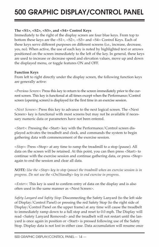
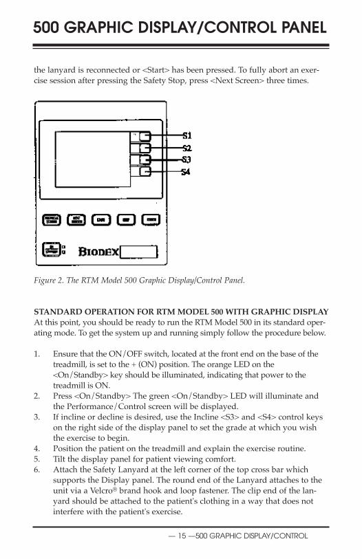
The <S1>, <S2>, <S3>, and <S4> Control KeysImmediately to the right of the display screen are four blue keys. From top to
bottom these keys are the <S1>, <S2>, <S3> and <S4> Control Keys. Each of
these keys serve different purposes on different screens (i.e., increase, decrease,
yes, no). When active, the use of each key is noted by highlighted text or arrows
positioned on the screen immediately to the left of the key. In general, these keys
are used to increase or decrease speed and elevation values, move up and down
the displayed menu, or toggle features ON and OFF.
Function KeysFrom left to right directly under the display screen, the following function keys
are generally active:
<Previous Screen>: Press this key to return to the screen immediately prior to the cur-
rent screen. This key is functional at all times except when the Performance/Control
screen (opening screen) is displayed for the first time in an exercise session.
<Next Screen>: Press this key to advance to the next logical screen. The <Next
Screen> key is functional with most screens but may not be available if neces-
sary numeric data or parameters have not been entered.
<Start>: Pressing the <Start> key with the Performance/Control screen dis-
played activates the treadbelt and clock, and commands the system to begin
gathering data with commencement of the exercise session.
<Stop>: Press <Stop> at any time to ramp the treadmill to a stop (pause). All
data on the screen will be retained. At this point, you can then press <Start> to
continue with the exercise session and continue gathering data, or press <Stop>
again to end the session and clear all data.
NOTE: Use the <Stop> key to stop (pause) the treadmill when an exercise session is inprogress. Do not use the <On/Standby> key to end exercise in progress.
<Enter>: This key is used to confirm entry of data on the display and is also
often used in the same manner as <Next Screen>.
Safety Lanyard and Safety Stop: Disconnecting the Safety Lanyard (to the left side
of Display/Control Panel) or pressing the red Safety Stop (to the right side of
Display/Control Panel on the upper frame) at any time will cause the treadbelt
to immediately ramp down to a full stop and reset to 0.0 mph. The Display will
read <Safety Lanyard Removed> and the treadbelt will not restart until the lan-
yard is once again in position or <Start> is pressed following use of the Safety
Stop. Display data is not lost in either case. Data accumulation will resume once
500 GRAPHIC DISPLAY/CONTROL PANEL
500 GRAPHIC DISPLAY/CONTROL PANEL— 14 —
500 GRAPHIC DISPLAY/CONTROL PANEL
— 15 —500 GRAPHIC DISPLAY/CONTROL
the lanyard is reconnected or <Start> has been pressed. To fully abort an exer-
cise session after pressing the Safety Stop, press <Next Screen> three times.
Figure 2. The RTM Model 500 Graphic Display/Control Panel.
STANDARD OPERATION FOR RTM MODEL 500 WITH GRAPHIC DISPLAYAt this point, you should be ready to run the RTM Model 500 in its standard oper-
ating mode. To get the system up and running simply follow the procedure below.
1. Ensure that the ON/OFF switch, located at the front end on the base of the
treadmill, is set to the + (ON) position. The orange LED on the
<On/Standby> key should be illuminated, indicating that power to the
treadmill is ON.
2. Press <On/Standby> The green <On/Standby> LED will illuminate and
the Performance/Control screen will be displayed.
3. If incline or decline is desired, use the Incline <S3> and <S4> control keys
on the right side of the display panel to set the grade at which you wish
the exercise to begin.
4. Position the patient on the treadmill and explain the exercise routine.
5. Tilt the display panel for patient viewing comfort.
6. Attach the Safety Lanyard at the left corner of the top cross bar which
supports the Display panel. The round end of the Lanyard attaches to the
unit via a Velcro® brand hook and loop fastener. The clip end of the lan-
yard should be attached to the patient's clothing in a way that does not
interfere with the patient's exercise.

500 GRAPHIC DISPLAY/CONTROL PANEL
500 GRAPHIC DISPLAY/CONTROL PANEL— 16 —
NOTA: La déconnexion de la sangle de sécurité (côté gauche du panneau d'af-fichage et de contrôle) ou l'actionnement du bouton rouge d'arrêt d'urgence (côtédroit du panneau d'affichage et de contrôle) entraîneront à tout. moment l'arrêtprogressif du tapis et le réglage de la vitesse à 0.0 kn/heure. L'afficage indiqueraqu'il y a eu un probléme de sécurité et le tapis ne redémarrera pas tant que la san-gle ne sera pas bien positionnée. De la même façon, aprés l'arrêt par le bouton d'ur-gence, le tapis ne démanera pas tant que le bouton de démarrage ne sera pas action-né. Les données affichées ne seront perdues ni dans l'un ni dans l'autre cas.L'enregistrement des données reprendra une fois la sangle sera reconnectée et que lebouton de démarrage aura été actionné. Pour arrêter complétement une séanceaprés un arrêt de sécurité, appuyer sur la touche commande d'effaçage.
NOTE: Disconnecting the Safety Lanyard (left side of Display/Control Panel) orpressing the Red Comfort Stop (atop the right side of Display/Control Panel) atany time will cause the treadbelt to immediately ramp down to a full stop andreset to 0.0 mph. The Display will read <Safety Lanyard Removed> and the tread-belt will not restart until the lanyard is once again in position or <Start> ispressed following use of the Safety Stop. Display data is not lost in either case.Data accumulation will resume once the lanyard is reconnected or <Start> hasbeen pressed. To fully abort an exercise session after pressing the Safety Stop, press<Next Screen> three times.
7. Use the Speed <S1> and <S2> control keys on the right side of the displayto adjust the speed to the desired level. The speed will immediatelyrespond to your input so be sure to inform the patient that the treadmillwill begin to operate. Gathering of data begins immediately at the pointfrom which the treadmill begins to move in either forward or reversedirection. A detailed description of the data that can be gathered is provid-ed later in this manual.
8. Press <Stop> to stop (pause) the treadmill at any time while still retainingall current data on the display screen.
9. Press <Stop> again to clear display data and reset settings to their defaultvalues.
AvErTissEmENT: Appuyer toujours sur la touche ARRET pour interrompre unexercise en cours. Ne pas appuy er sur la touche ATTENTE anant I'arrét completdu tapis. La touche ARRET antraíne une décélération progressive et toutes les don-nées sont sauvegaardées. Si on était à appuyer sur la touche ATTENTE, non seule-ment on perdrait les données mais ela entraínerait aussi un arrét brutal du tapis.
CAUTiON: Always press <Stop> to stop the treadmill when patient exercise is inprogress. Do not press <On/Standby> to clear the system of data until the treadmillbelt has completely stopped moving. The <Stop> key will cause the treadmill to rampsmoothly to a stop, all display data will be retained. Pressing the <On/Standby> willclear all data from the display and stop the treadbelt more abruptly.
!
!
!
!

500 GRAPHIC DISPLAY/CONTROL PANEL
— 17 —500 GRAPHIC DISPLAY/CONTROL
NOTE: BELT MOVEMENT WHILE AT ZERO SPEEDInherent “belt creep” is common with Pulse Width Modulation Motor Control. Allowthe treadmill sufficient time to “warm up” prior to making any adjustments for beltcreep. See “Zero Balance” in the “System Utilities” section of this manual for instruc-tions on treadbelt adjustments.
THE PERFORMANCE/CONTROL SCREEN (See Figure 3.)Now that your system is up and running, it’s time to take a closer look at thePerformance/Control screen. This screen is displayed any time the Biodex RTMModel 500 Treadmill is ready to operate. It is the first screen that appears uponpower-up and the screen from which both initial speed and incline/decline para-meters are set.
The Performance/Control screen provides the user with immediate biofeedbackin both numeric and graphic displays. All data displayed is current for the exer-cise session in progress. The Performance (left) side of the screen can display thefollowing data when the system is in standard operating mode. Note that somedisplay categories must be activated through the Configure Menu to appear onthe display, i.e., Calories Per Hour instead of METs.
Figure 3. The Performance/Control screen provides the user with both graphic andnumeric displays. Patient Performance data is displayed on the left side of the screenwhile system control information is displayed on the right side of the screen.
Time: Cumulative time in minutes/seconds from the point at which the tread-belt begins to move in either direction.
Miles/Kilometers: The distance covered in miles or kilometers from the beginningto the end of the current exercise session.
Calories: Total calories burned by the user during the current exercise session.This value is displayed in real-time.
Calories Per Hour: Total calories that will be burned in one hour if exercise con-tinues at the current rate.

500 GRAPHIC DISPLAY/CONTROL PANEL
500 GRAPHIC DISPLAY/CONTROL PANEL— 18 —
METs: The METs value reflects the resting rate of Oxygen consumption with one
MET equal to the Oxygen consumption of a seated individual at rest. Thus, a seat-
ed individual in a resting state is consuming 1 MET. A seated individual exercising
at a rate of 2 METs is consuming twice the Oxygen of a seated, resting individual. A
person exercising at 10 METs is consuming ten times the Oxygen of a seated, rest-
ing individual. To compute the METs of a person actively exercising on the RTM
Model 500 Treadmill, the system uses standard calculations based on American
College of Sports Medicine Guidelines for Testing and Exercise. On the RTM 500
Treadmill, the MET’s value is always displayed in real-time for current speed.
Heart Rate: This is the real-time heart rate of the patient during the exercise session.
Target Heart Rate: This is an exact heart rate value, entered by the clinician, (i.e.,
105 beats per minute). It serves as a biofeedback component for the patient who
can be instructed to match, exceed or not to exceed this value.
The Control side of the Performance/Control screen displays the following para-
meters when the system is in standard operating mode:
Speed: The speed range of the Biodex Rehabilitation Treadmill is 0 mph to +8.0
mph and 0 to 3 mph in reverse. For both forward and reverse directions, press-
ing the <S1> button makes the treadbelt go faster while pressing the <S2> but-
ton causes the treadbelt to slow down. Press the <S1> button to increase tread-
belt speed in 0.1 mph increments.
Incline or Decline: The <S3> and <S4> Incline Control keys are used to increase or
decrease treadmill grade. Press the <S3> key to increase the grade and the <S4>
key to decrease the grade. Note that there is a slight delay between movement of
the Elevation display bar and the actual movement of the treadmill.
NOTE: To change the default settings for any of the above parameters, see “SystemUtilities” later in this chapter.
THE EXERCISE SETUP SCREEN (See Figure 4.)The Exercise Setup screen allows the user to set default values for daily parameters
including Weight units, Target Heart Rate, Exercise Duration, and treadbelt direction.
To Access the Exercise Setup Screen:
1. At the Performance/Control screen press <Next Screen>.
2. At the Main Menu, use the <S1> or <S2> key to highlight “Exercise Setup.”
Press <Next Screen> to bring up the Exercise Setup screen.
Setting and Changing Exercise Default ValuesThe Exercise Setup screen displays the default settings for certain patient proto-
cols. These default settings can be changed at any time as described below.

500 GRAPHIC DISPLAY/CONTROL PANEL
— 19 —500 GRAPHIC DISPLAY/CONTROL
When you are finished selecting the new default values for any or all settings on
this screen, press <Next Screen> to advance to the Performance/Control screen
and begin the exercise session.
Figure 4. The Exercise Setup screen.
Weight: Press <S1> or <S2> to highlight the “Weight” value. Use the <S3> or
<S4> key to increase or decrease the weight displayed. The weight value is used
to calculate calories and calories per hour stats.
Target Heart Rate: Press <S1> or <S2> to highlight “Target Heart Rate.” Use the
<S3> or <S4> key to increase or decrease the Target Heart Rate value. (Target Heart
Rate is functional only if it has been activated through the Configure screen.)
Exercise Duration: Press <S1> or <S2> to highlight “Exercise Duration.” Use the
<S3> or <S4> key to increase or decrease the time value for this parameter. If
nothing is entered for this parameter, the “Time” value will automatically
default to cumulative time (count up from 0:00).
Treadmill Direction: Press <S1> or <S2> to highlight “Treadmill Direction.” Use
the <S3> or <S4> key to select forward or reverse treadbelt direction.
SYSTEM UTILITIES (See Figure 5.)The System Utility Menu allows users to choose between various display options
and to set specific parameters for a variety of treadmill functions. It is from this
menu that all system utility options are accessed, selected and/or programmed.
To access the Configure Menu:1. Press <ON/STANDBY> to turn the treadmill ON. The
Performance/Control screen should appear on the display.
2. Press <Next Screen>. The Main Menu screen should be displayed.

500 GRAPHIC DISPLAY/CONTROL PANEL
500 GRAPHIC DISPLAY/CONTROL PANEL— 20 —
3. Use the <S1> or <S2> key to highlight “System Utilities” and then press
<Next Screen>. The System Utilities menu should now be displayed.
4. Use the <S1> or <S2> key to highlight “Configure” and then press <Next
Screen>. The Configure menu should now be displayed.
Configure Options All System Utility functions are accessed from the Configure Menu. From this
menu the user can choose items, toggle “Yes” or “NO” for specific features, and
increase or decrease numeric parameters.
Following is a line by line description of the Configure screen options and para-
meters. As a general rule, use the <S1> and <S2> keys to highlight (choose) or
activate options. Use the <S3> and <S4> keys to adjust numeric values. Once all
parameters are set as desired, press <Next Screen> or <Previous Screen> to exit
to return to the Main Menu.
Figure 5. The Configure Screen.
Heart Rate: If active, this function causes the patient’s Heart Rate to be displayed
on the screen in both numeric and graphic formats. Use <S1> or <S2> to high-
light this option, then use the <S3> or <S4> keys to activate or void this func-
tion.
NOTE: The Heart Rate function will not operate unless the Heart Rate Monitor isattached to both the patient and the display panel.
Measurement Units: The Biodex RTM 500 Treadmill can be configured to display
either standard English or Euro (metric) measurements. To change units use the
<S1> or <S2> keys to highlight this option, then use the <S3> or <S4> key to
toggle from one format to the other.

500 GRAPHIC DISPLAY/CONTROL PANEL
— 21 —500 GRAPHIC DISPLAY/CONTROL
Contrast: Screen contrast is easily adjusted. Use the <S1> or <S2> key to high-
light this option, then use the <S2> or <S3> key to select the desired level.
Selecting low numbers will result in a darker screen while selecting high num-
bers makes the screen appear brighter. Contrast levels range from 0 to 15.
Language: This option is for future use when the treadmill will be able to display
in German, French, Japanese and English.
Work Rate: This can be displayed on screen in either MET’s or Calories/Hour.
Use the <S1> or <S2> keys to select this option, then use the <S3> or <S4> keys
to toggle from one format to the other.
Zero Balance: This option is used to correct treadbelt “creeping” which may occur
at the zero speed setting due to changes in temperature, heavy use, etc. Use the
<S1> or <S2> key to select this option, then use the <S3> or <S4> key to raise or
lower the Zero Balance setting anywhere between 0 and 15. Values 0 to 7 set
treadmill motion in reverse, 8 through 15 set treadmill motion in the forward
direction (8 is the default value.)
Incline: The RTM Model 500 can be configured with Incline/Decline of either -3
to 12 degrees or 0 to 15 degrees. This setting is preset at the factory, prior to ship-
ping, based on the configuration selected. If, for some reason, this setting is not
correct, use the <S1> or <S2> key to select this option, then use the <S3> or <S4>
key to select the appropriate format.
Resistive Gait: (Optional): This option allows the patient to simulate pushing or
pulling a specified load while walking, jogging or running. A specially designed
microprocessor circuit measures the horizontal force applied to an optional,
instrumented handlebar and varies the treadmill speed to maintain that force at
a preselected level. For more detailed information on this option, see Chapter 5.
Software Version / Hours of Use: Listed at the bottom left side of the Configure
Menu screen are the version identification number of your RTM Model 500 soft-
ware and, at bottom right, the cumulative hours of use for this system. Both are
displayed at all times while the Configure Menu is displayed.
USING THE HEART MONITORING FEATURE (OPTIONAL)
Activating Heart Rate Monitoring
If the Heart Rate Monitoring function is currently active, the Performance/Control
screen will show the Target Heart Rate value. If the Target Heart Rate value box is
blank, you must activate the Heart Rate Function as follows.

500 GRAPHIC DISPLAY/CONTROL PANEL
500 GRAPHIC DISPLAY/CONTROL PANEL— 22 —
1. At the Performance/Control screen, press <Next Screen>. The Main Menu
screen should be displayed.
2. Use the <S1> or <S2> key to highlight “System Utilities” and then press
<Next Screen>. The System Utilities Menu should now be displayed.
3. Use the <S1> or <S2> key to highlight “Configure” and then press <Next
Screen>. The Configure Screen should now be displayed.
4. Use the <S1> or <S2> key to highlight “Heart.”
5. Use the <S3> or <S4> key to toggle the “Heart” setting to “Yes” or “No”.
6. Press <Next Screen> to return to the System Utilities Menu, then use the
<S1> or <S2> key to highlight “Return To Main Menu.”
7. Press <Next Screen> to return to the Main Menu.
Setting Target Heart RateOnce the Heart Rate function has been activated, the next step is to enter the
Target Heart Rate value. The following chart depicts standard Target Heart Rate
ranges for optimum cardiovascular benefit. While this chart may be used as a
guide for cardiac-healthy users, clinicians must be sure to set the Target Heart
Rate based on individual patient protocol.
ADvErTissEmENT: Quand I'appareil est untilisé en thérapue, le médecinresponsable doit définir les paramétres spécifiques en patient pour limiter toutrisque et nnotamment le travail total et la fréquence cardiaque.
CAUTiON: When prescribed for the Therapeutic purposes, a physician shouldclearly define the parameters of use (i.e., total work, maximum heart rate, etc.) toreduce the risk of patient injury.
Target Heart Rate Chart
Age Estimated Maximal 85% 70%Attainable Heart Rate Level Level
20 200 170 140
25 195 166 136
30 190 162 133
35 185 157 129
40 180 153 126
45 175 149 122
50 170 145 119
55 165 140 115
60 160 136 112
65 155 132 108
!
!

500 GRAPHIC DISPLAY/CONTROL PANEL
— 23 —500 GRAPHIC DISPLAY/CONTROL
To Set Target Heart Rate1. At the Main Menu, use the <S1> or <S2> key to highlight “Exercise Setup.”
Press <Next Screen> to bring up the Exercise Setup screen.2. Use the <S1> or <S2> keys to highlight “Target Heart Rate.”3. Use the <S3> or <S4> key to increase or decrease the Target Heart Rate
value as desired.4. Press <Previous Screen> to return to the Performance/Control screen. The
Target Heart Rate value should now be displayed in the Target Heart Ratevalue box.
Connecting the Heart Rate MonitorWith the Heart Rate Monitoring feature activated, the Heart Rate Monitor pro-vides a real-time reading of the patient’s heart rate. The numeric values dis-played in the Heart Rate Box on the Performance/Control screen mirror theactual heart rate. The graph at the bottom of the screen provides a windowshowing between + or 20 beats per minute from the Target Heart Rate setting.
To Connect the Heart Rate Monitor to the Patient:1. Instruct the patient to secure the Heart Rate Monitor Strap around the chest
so that it is in direct contact with the skin just below the breast. (The strapshould be dampened with a sponge or wet cloth to ensure maximum con-ductivity or you can use the Spectra 360 Electrode Jell provided with theoptional Heart Rate Kit.)
2. Insert the female adapter of the Heart Rate Cord onto the male adapter onthe strap. Run the cord out from under the shirt on the same side as thedisplay’s Heart Rate plug.
3. Press <On/Standby> to turn the treadmill OFF. Instruct the patient tostand on the treadmill so that he or she is facing the display panel.
4. Install the male end of the Heart Rate Cord into the display’s Heart Rateplug, located on the right edge of the display.
5. Press <On/Standby> to turn the unit ON.6. At this point, your real-time heart rate should be shown on the display.
Ensure the heart rate is displayed before proceeding. If the heart rate is notdisplayed, or appears to be incorrect, adjust the Heart Rate Monitor Strap forimproved conductivity. (You may want to take the user’s pulse rate manual-ly and compare it against the displayed heart rate to confirm accuracy.)
7. Begin the exercise session.
PROGRAMMABLE OPTIONSThe Biodex RTM Model 500 Treadmill provides storage for eight programs. Fourprograms are pre-loaded and can be modified by the user. These programs allowthe clinician to select predetermined exercise format routines. Each protocol canbe set to provide up to five levels of exercise ranging from light (level 1) toheavy (level 5). Users can select any of the pre-defined exercise protocols, reviewor edit any protocol, or delete an existing protocol.

500 GRAPHIC DISPLAY/CONTROL PANEL
500 GRAPHIC DISPLAY/CONTROL PANEL— 24 —
Choosing A Pre-Defined Exercise Program (See Figure 6.)The Biodex RTM Model 500 Treadmill comes with four pre-defined exercise pro-grams already installed. These programs offer a variety of options for standard-izing patient exercise. Each program has been designed to provide a mix of pro-gram lengths, speeds, inclines and declines during the session. Each program isdivided into ten segments.
Figure 6. Pre-defined and user customized programs are available to fit a wide array ofpatient needs.
To access the Biodex Pre-defined Exercise Programs:1. At the Performance/Control screen press <Next Screen>. 2. At the Main Menu, use the <S1> or <S2> key to highlight “Programmable
Options.” Press <Next Screen>.3. At the Programmable Options screen, use the <S1> or <S2> key to high-
light “Choose Program.” Press <Next Screen>.4. From the Programmable Options screen use the <S1> or <S2> key to high-
light the desired program, (press <Next Screen> to view programs 5-8).5. Press <Enter> to select the highlighted protocol and return to the
Performance/Control screen. The selected exercise program number will bedisplayed in the bottom right corner on the “Control” side of the screen.
6. Use the <S2> or <S3> key to select the desired exercise level for the select-ed protocol.
NOTE: Each level of exercise is equal to 20% of maximum patient effort. Thus, level #5requires 100% effort while level 1 requires only 20% effort from the patient.
7. Press <Start> to begin the exercise session. A graph depicting the selectedexercise program will be displayed at the bottom of thePerformance/Control screen.
8. Use the <S2> or <S3> key to further increase or decrease the exercise levelas required by patient protocol.

500 GRAPHIC DISPLAY/CONTROL PANEL
— 25 —500 GRAPHIC DISPLAY/CONTROL
Reviewing and Editing ProgramsThe RTM Model 500 treadmill exercise programs are easy to review and edit.
Reviewing allows the clinician to examine all segments of any program without
changing the program values or parameters. Editing allows the clinician to make
and save changes to any of the eight programs.
To Review Any Exercise Program:
1. At the Performance/Control screen press <Next Screen>.
2. At the Main Menu, use the <S1> or <S2> key to highlight “Programmable
Options.” Press <Next Screen>.
3. At the Programmable Options screen, use the <S1> or <S2> key to high-
light “Review or Edit Program.” Press <Next Screen>.
4. From the Programmable Options screen, use the <S3> or <S4> key to scroll to
the desired program as indicated in the Program Box at the right of the screen.
For any program displayed in the Program Box, all parameters are displayed
on the left side of the screen. Press <Enter> to select the desired protocol.
6. Press <Next Screen> to return to the Performance/Control screen after you
have finished reviewing the program. The last program reviewed is now
the currently selected program and will be shown as such in the bottom
right corner of the Performance/Control screen.
To Edit Any Exercise Program:
1. At the Performance/Control screen press <Next Screen>.
2. At the Main Menu, use the <S1> or <S2> key to highlight “Programmable
Options.” Press <Next Screen>.
3. At the Programmable Options screen, use the <S1> or <S2> key to highlight
“Review or Edit Program.” Press <Next Screen> to reveal the Program Box.
4. Use the <S3> or <S4> key to scroll to the desired program number as
shown in the Program Box on the right side of the screen.
NOTE: If a program is currently selected, it will automatically be displayed in the pro-gram box.
5. Press <Enter> to select and display the program to edit as listed in the
Program Box.
6. Use the <S3> and <S4> keys to select the stage (1 - 10) of the protocol to edit.
7. Press <Enter> to move across the program table columns as desired from
Stage to Speed to Index to Time and, eventually, back to Stage.
8. Use the <S1> and <S2> keys as plus or minus buttons to raise or lower the
numeric value of the selected program stage or parameter.
9. After making all edits to the selected program, use the <Enter> key to advance
across the parameters until the “Stage” column is once again highlighted.
10. Press <Next Screen> to save all changes and return to the
Performance/Control screen with the edited program now selected and

500 GRAPHIC DISPLAY/CONTROL PANEL
500 GRAPHIC DISPLAY/CONTROL PANEL— 26 —
displayed at the bottom of the screen, or press <Previous Screen> to abort
the edit option without saving the changes and return to the Programmable
Options screen.11. You can now begin an exercise session using the selected program or
choose a new exercise program, if desired, as described previously.
Figure 7. The Performance/Control screen displays a graph in the lower left cornerdepicting any selected pre-defined or customized programs.
Deleting ProgramsIf desired, an entire Exercise Program can be quickly deleted from the RTM 500Treadmill memory.
To Delete Any Exercise Program From Memory:1. At the Performance/Control screen press <Next Screen>. 2. At the Main Menu, use the <S1> or <S2> key to highlight “Programmable
Options.” Press <Next Screen>.3. At the Programmable Options screen, use the <S1> or <S2> key to high-
light “Delete Program.” Press <Next Screen> to reveal the Program Box.4. Use the <S3> or <S4> key to scroll to the desired program number as
shown in the Program Box on the right side of the screen.
NOTE: If a program is currently selected, it will automatically be displayed in the program box.
5. Press <Enter> to select and display the program to delete as shown in theProgram Box.
6. Press <Enter> to confirm deletion of program displayed in Program Box.7. Press <Previous Screen> to return to the Programmable Options screen after
deleting the selected program or press <Enter> to continue deleting programs.

RESISTIVE GAIT TRAINING
— 27 — RESISTIVE GAIT TRAINING
(Optional for RTM Model 500 With Graphic Display)Resistive Gait Training is a common practice in most physical therapy clinics. In
the usual scenario the patient is simply asked to walk forward or backward
while pushing or pulling a specific load. This can be accomplished with the use
of a chair or sled, the load being varied by the addition or subtraction of weights
on the seat. In some clinics, various weight machines or elastic tubing are used
to serve the same purpose with the patient walking backward or forward, to the
extent allowed by the cable travel, while pulling or pushing the handle. The load
is varied by selecting different weights or elasticity on the machine.
Obviously, the room needed for the chair and sled methods of supplying resistive
gate exercise is a drawback. Similarly, the short travel of the cable on a weight
machine makes it difficult to get the most out of each exercise session. That’s
where the new Biodex RTM Model 500 Treadmill comes to the rescue. With no
mechanical limits to time or distance whatsoever, the Biodex RTM Model 500
allows patients to push or pull a specified load while walking. A specially fitted,
optional, instrumented handlebar installed just below the display panel allows
users to push forward or pull backward while using their hands on the bar. If
desired, a special waist harness can also be fitted to the patient allowing the han-
dle to be pulled forward or pushed in reverse without use of the hands.
Simply providing resistive gait training capability is a noteworthy advancement
in treadmill design, but the Biodex RTM Model 500 goes a step further. It also
provides a means of maintaining preselected force levels throughout the exercise
session. By utilizing a specially designed microprocessor circuit, the RTM Model
500 can measure the horizontal force applied to the handlebar at all times and
then vary the speed of the treadmill to maintain that force at a constant level.
Lighten up and the treadmill belt slows down, exceed the preselected force level
and the RTM Model 500 quickens its pace.
NOTE: For resistive gait training, mechanical work and power are measured and report-ed on the Performance/Control screen.
Activating the Resistive Gait Training FunctionTo activate the Resistive Gait Training Function:
1. At the Performance/Control screen, press <Next Screen>. The Main Menu
screen should be displayed.
2. Use the <S1> or <S2> key to highlight “Resistive Gait Setup.” Press <Next
Screen>. The Resistive Gait Setup Screen should now be displayed.
3. Use the <S1> or <S2> key to highlight “Weight” and then use the <F3> or
<F4> key to enter the patient weight.
4. Use the <S1> or <S2> key to highlight “Target” and then use the <F3> or
<F4> key to enter the patient’s Target Heart Rate.

RESISTIVE GAIT TRAINING
RESISTIVE GAIT TRAINING — 28 —
5. Use the <S1> or <S2> key to highlight “Exercise Duration” and then use
the <F3> or <F4> key to enter the desired exercise duration value.
6. Use the <S1> or <S2> key to highlight “Resistive Gait” and then use the
<F3> or <F4> key to select “Push” or “Pull.”
7. Press <Next Screen> to return to the Performance/Control Screen. The
Resistive Gait function should now be active.
8. Use the <F1> and <F2> keys to set the desired resistance level (Force).
9. Use the <F3> and <F4> keys to set incline/decline.
10. Press <Start> to begin the resistive gait exercise session. The treadbelt will
begin to move once the patient provides sufficient force in the required
direction (push or pull).
The Resistive Gait Performance/Control ScreenWith the Resistive Gait Training function selected, the Performance/Control Screen
is modified slightly to provide information specific to this task. The “Calories” dis-
play is replaced by Work in Kilojoules and the MET’s display is replaced by Power
in Watts. Following are definitions for these additional measurements.
Kj = The amount of work being done on the resistive gait bar. For this measure-
ment, the actual force applied to the bar (push or pull) is multiplied by the dis-
tance traveled by the treadmill belt.
Watts = The power (joules/sec) being applied to the resistive gait bar.
NOTE: To return to normal operating mode after you have selected the Resistive Gaitoption, press <Next Screen> to return to the Main Menu. Now select ExercisePrograms and then press <Next Screen> twice. The Performance Control Screen shouldnow be displayed with its normal settings.

MAINTENANCE
— 29 — MAINTENANCE
Your Biodex RTM Model 400 or Model 500 Treadmill should provide trouble-free operation as long as the following maintenance procedures are performed.If you are using the RTM Model 400 with Numeric Display, automatic promptswill appear when specific hours of usage are reached (see chart below).
If you are using the RTM Model 500 with Graphic Display, no prompts are pro-vided so you must adhere to the hours of usage guidelines in the chart below.
NOTE: Without proper maintenance, excessive wear to drive components will occur. Toassure trouble-free operation, scheduled maintenance must be performed. Failure toadhere to the scheduled maintenance chart below will void your warranty.
INSTRUCTION HOURS OF USAGE LED DISPLAY CODELubricate Deck 75 P1Reverse Deck 1,000 P2Belt Replacement 1,000 P3Clean Motor and Amp 750 P4Front Roller Cleaning 375 P5
NOTE: Once the required maintenance has been performed, the RTM Model 400 mainte-nance prompt can be cleared by pressing <Select Display> twice, followed by <Clear Display>twice. The Maintenance Hour Log for the specific prompt displayed will reset to zero.
Daily MaintenenceAs required, clean all exterior surfaces, upholstery and restraining straps.Specialized vinyl cleaners or protectants are recommended for upholstery andcushions. Otherwise, use a solution of warm water and mild detergent.
NOTE: DO NOT use solutions containing ammonia.
Hardware computer components should be wiped clean as needed using a softrag dampened with alcohol.
Quarterly: Lubricate Treadbelt and Slider DeckThe Biodex Lubricant Kit is designed to reduce friction between the treadbeltand the slider deck. It is required for all institutional treadmills. Proper andtimely application of the lubricate will prevent premature failures due to exces-sive wear and load. Items affected by inadequate lubrication are the treadbelt,slider deck, motor, and motor controller.
Annually or Every 1,000 Hours: Reverse Exact-Track BedReverse the Exact-Track bed. The treadmill bed is double-sided, allowing it to bereversed and used over. Once both sides have been used, the bed must be replaced.
Annually or Every 1,000 Hours: Replace TreadbeltInspect Treadmill for cracks or tears. If none are found, continue to use. If anycracks or tears are apparent, replace treadbelt.

MAINTENANCE
MAINTENANCE — 30 —
MAINTENANCE PROCEDURES
Treadmill Lubrication (See Figure 8.)
1. Using the large syringe provided, squirt one-half tube of the lubricant
underneath the center of the treadbelt.
2. Walk 10 steps on the treadmill at a speed of 1.0 mph. This will moisten an
8” track underneath the center of the entire treadbelt.
3. Allow the treadmill to dry for approximately 10 minutes.
NOTE: Use only the Biodex lubricant kit with your RTM Model 400 or Model 500Treadmill. Most standard greases, waxes and silicon sprays will build up on the rollers,causing belt slippage and affecting tracking.
To re-order lubricant kit, use Biodex part # 945-276. Each container provides 12
applications.
Figure 8. Squirt one-half tube of lubricant between the belt and deck.
Reverse or Replace Treadbelt and DeckTools Required: Phillips Screwdriver, 9/16 Socket, 3/16 and 5/32 Allen Wrench
1. Elevate treadmill to 10 degrees, allowing access to the underside of the
treadmill.
2. Remove power cord from wall outlet.
3. Remove motor cover secured by the six Phillips head screws. Once screws
are removed, lift and remove cover.
4. Remove motor tension lock nut, located on the underside of accessory pan.
The nut is attached to the motor bracket tensioning bolt. Once the tensioning
bolt has been removed, lift the motor up and remove motor drive belt.
5. Remove the two aluminum traction strips, located one on each side of running
deck. These are secured by 4 Allen screws located on top of traction strips.
MAINTENANCE
— 31 — MAINTENANCE
6. Remove rear treadbelt roller. The roller is secured by two treadbelt tension-
ing bolts. Once bolts have been removed, lift out the roller assembly.
7. Remove the 2 Allen screws which secure the front treadbelt roller. The
screws are located on the side of the treadmill.
ATTENTiON: Si les boutons de sécurité du rouleau sont retirés, le rouleau
chutera. Ne oas oublier que les rouleaux sont lourds.
CAUTiON: When the bolts securing the roller are removed the roller will drop. Be aware that the rollers are heavy.
8. Remove the running deck. This is done by lifting from the side of the deck
and raising the deck two inches before sliding it out. The running deck is
two-sided and can be flipped over and reused once.
9. To remove the treadbelt seven support brackets must be removed. These
are comprised of 3 angle iron brackets attached by securing nuts, and 4
running deck support bars secured by Allen screws. Once all support
brackets are removed the treadbelt can be removed.
10. Tension treadbelt and adjust tracking after you reassemble the treadmill.
(See Treadbelt Adjustment procedure.)
Treadbelt AdjustmentAlthough the RTM Treadmill incorporates the “Exact Track System,” occasional
belt adjustments are still necessary for correct tensioning and tracking.
Tension Adjustment
ATTENTiON: Avant de tester la tension du tapis selon la procédure décrite ci-dessons, méttre le tapis à l'arrêt et déconnecter le câble secteur. Certaines piéces dutapis peuvent entrainer des blessures graves. Ne jamais essayer de déterminer latension sur le tapis pendant que ce dernier est en mouvement.
CAUTiON: Before testing treadbelt tension as described below, turn the treadmillOFF and unplug the system. Moving parts on the treadmill can cause seriousinjury. Do not attempt to determine treadbelt tension while the belt is moving.
The need for tension adjustment is indicated by uneven belt speed or the belt
stopping suddenly upon foot impact. Properly tensioned, the tread belt will
allow the user to slip a hand snugly under the center of the belt.
Tread belt tension is adjusted by tightening or loosening the two hex-head, 9/16,
bolts at the end of the treadmill frame. The bolts should be adjusted in 1/4-turn
increments, exactly the same amount, in the same direction. Turn both bolts
!
!
!
!

MAINTENANCE
MAINTENANCE — 32 —
clockwise to tighten the belt. Turn both bolts counterclockwise to loosen the belt.
Failure to turn both bolts equally may affect tracking. One quick test is to apply
hand heel strikes and observe if belt momentarily stops. If belt speed remains
constant, this indicates belt is tight. If belt hesitates during heel strikes, addition-
al tightening is required. To check over tightening, set treadmill .5 mph and,
while holding rail, resist until belt stops. If drive roller continues to rotate with
the belt stopped, further adjustment is not necessary. If drive roller stops when
belt is stopped, belt is too tight. Loosen belt and recheck.
TrackingTracking adjustment is necessary when a pronounced bump appears toward the
left side of the belt, approximately 2 inches from the left edge. This occurs when
the belt works its way out of the Exact-Track grooves.
To Adjust Treadbelt Tracking:
Tighten the hex tensioning bolt on the side to which the treadbelt has migrated,
turn bolt in 1/8 increments clockwise. The tread belt should slowly move away
from the tightened bolt. Once belt migrates back into roller slot the bump will
disappear. At this point, fine tracking adjustment is necessary.
Fine TrackingFine tracking adjustment prevents premature wear of the tacking belt rib which
rides in the Exact-Track groove. The belt rib should be centered in the tracking
groove. If the rib rides against the groove wall, a friction point forms causing
excessive wear. This adjustment should be made during preventative mainte-
nance or during belt replacements.
To Adjust Fine Tracking:
Determine which side of the exact track groove the belt rib is riding on. Mark
treadbelt tracking position on deck.
Tighten the hex tensioning bolt on the side the belt is tracking against, belt
should migrate to the opposite side of the groove. Mark the tread belt tracking
position on the deck. You now have two (2) marks on the deck 1/4” apart. Mark
the center position of the marks. This is where the belt should track. Adjust
9/16 tensioning bolt so that the belt is centered on the mark. Remember the belt
will migrate away from the tension bolt that is adjusted last. Tracking adjust-
ments are done in forward direction only, at 8 mph.
Check tensioning after adjustment to insure proper belt performance and wear.
NOTE: Motor drive belt should never slip. Check this when you check for tread beltovertightening. If tread belt drive roller is stopped, motor should also stall. If motorturns, but drive roller is stopped, tighten motor tension bracket located under the mill.Adjust until the motor belt stops slipping.

TROUBLESHOOTING
— 33 — TROUBLESHOOTING
SYMPTOMTreadmill is turned ON and speed control is inoperable (belt not moving).
1. Check for faults on display unit before moving onto step #2:
For RTM Model 400 with Numeric Display the following diagnostic error codes apply:
CODE DESCRIPTIONA1 Motor Amplifier Fault
A2 Upper Board NV Ram Failure
A3 Upper Board PROM
A4 Upper Board RAM
A5 Upper Board Communication Failure RS-232
A6 Upper Board Communication Failure RS-422
A7 Lower Board PROM
A8 Lower Board RAM
A9 Not Used
b1 Lower Board Watchdog Failure
b2 Lower Board Watchdog Disabled
b3 Lower Board Controller Fault
b4 Hall No Speed
b5 Hall Over Speed
b6 Lower Board Loopback Comm Failure
b7 Upper Board Failure
b8 Not Used
b9 Not Used
E1 Grade Failure
P1 Deck Lubrication Maintenance
P2 Reverse Deck Maintenance
P3 Belt Replacement Maintenance
P4 Motor & Amp Cleaning
S1 Tach Overspeed
S2 Tach No Speed
For RTM Model 500 with Graphic Display the following diagnostic error codes apply:
CODE DESCRIPTION
128 Communication between upper/lower board inop 128
64 No Safety Lanyard 64
32 Control fault (no amplifier) 32
16 Grade Error 16
8 Motor Tach Output Exceeds Selected Speed 8
4 Motor Tach Output is Below Selected Speed 4
1 Hall Sensor Output is Below Selected Speed 1
2. If no faults are displayed check the following:
Large blue capacitor should measure 170 VOL across terminals. If OK, proceed
to step 3.
3. Speed control signal on motor amplifier should measure .250 VDC per mill
per hour E.G.
NOTE: Measurement taken at J1 Pin 1 PIN 2 1mph = .250 VDC2mph = .500 VDC4mph = 1.00 VDC8mph = 2.00 VDC
If speed control signals are OK, proceed to step 4.
4. Check Amplifier Output. The Output Terminals are located on top of
amplifier and are designated “m+” and “m-”. The Output voltage should
be: 1mph = 32 VAC, 2mph = 52 VAC
NOTE: Remember to use the volts A.C. selection on your meter. The Amplifier is pulsewidth modulating, therefore A.C. scale is required.
If amplifier output is OK, proceed to step 5.
5. Check Motor Resistance. The motor has a winding resistance of 1.3 to 3
Ohms. The value is dependent on commutation position. If resistance read-
ing is significantly higher the windings or brush contacts are defective.
To measure resistance turn treadmill power OFF. Place meter lead across termi-
nals marked “m+” and “m-”. Set meter scale to the lowest resistance selection.
Check resistance in several commutator positions by rotating motor shaft 9.0
degrees for every one revolution.
TROUBLESHOOTING
TROUBLESHOOTING — 34 —

RTM MODEL 400 WITH NUMERIC DISPLAYIn the unlikely event of a system malfunction, the following tests may be helpfulin pinpointing the problem source.
BUTTON TESTThis will test the functionality of the 14 buttons on the display panel. Listedbelow is the button designation and the display window codes displayed duringkey activation.
To activate the button test turn unit OFF then ON. While all LED’s are lit press<Stop> and the <Elevation -> buttons simultaneously. All LED’s should go OFF.If an error code is displayed note error and call Biodex Technical Support forassistance. To test individual buttons use chart below.
Depress each button to ensure proper operation. As each button is depressedthere should be a corresponding beep.
BUTTON DESIGNATION DISPLAY WINDOW
Select display 1Clear display 2Set weight 3Set time 4Scroll up 5Scroll down 6Speed up 7Speed down 8Grade up 9Grade down 10Forward 11Reverse 12Stop 13Start 14
MOTOR CURRENT TESTThe test verifies that the system is operating under normal motor current levels.A contributing factor is excess motor current is proper maintenance. As the fric-tion between the running deck and belt increases so does motor current. Listedbelow are typical current levels at specific speeds.
To activate motor current test turn system OFF and then ON. While all LED’Sare lit depress <Stop> and <Speed -> buttons simultaneously. Using the<Speed> buttons select speed as listed below to verify motor current values. Ifmotor current value varies by more than 20% refer to the maintenance section ofthe manual. If after maintenance is performed motor current value continues at20% above listed value contact Biodex Technical Support for assistance.
SYSTEM DIAGNOSTICS
— 35 — SYSTEM DIAGNOSTICS

SPEED MOTOR CURRENT (AMPS)
8.0 2.0
5.0 1.4
0.0 0.4
-3.0 1.2
RTM MODEL 500 WITH GRAPHIC DISPLAY
Diagnostic ModesIn the unlikely event of a system malfunction, two diagnostic modes are available
to help pinpoint the problem source. Use the Front Panel and Lower Unit
Diagnostic Modes in conjunction with the following troubleshooting procedures. If
further assistance is required, please call Biodex Customer Service at (800) 224-6339.
To Access the Diagnostic Mode:1. Turn power ON and press the ON button to activate the display. Upon
power-up the Performance/Control screen is displayed.2. Press <<Next Screen>> and the Main Menu will be displayed. Using the
<S1> and <S2> keys on right side of display, highlight system utilities andpress enter.
3. The system utilities menu has two selections; configure and return to mainmenu displayed. There are, however, three hidden selection that are dis-played after pressing <S3> then <S4> and <S3> again. They are calibration,diagnostics and reset programs.
4. Using the <S1> and <S2> key highlight “Diagnostics” and press <NextScreen>. The Diagnostics menu has three selections, each activated byhighlighting the selection with the <S1> or <S2> key and pressing the Startbutton. The Diagnostic menu selections are Button Test, Display Test andHardware Test, as described below.
Button TestThis will test the functionality of the 8 keys on the display panel. Listed below is the
key designation and the display window codes displayed during key activation.
KEY DESIGNATION DISPLAY WINDOW<S1> 1<S2> 2<S3> 3<S4> 4<Previous Screen> 5<Next Screen> 6<Start> 7<Enter> 8
SYSTEM DIAGNOSTICS
SYSTEM DIAGNOSTICS — 36 —

Stop and Standby/On button can not be tested. If you press Stop you will return
to Diagnostic menu. Pressing Standby turns the system OFF.
Display TestThis is selected by highlighting “Display Test” and pressing Start. Once activated
you should observe the display screen changing contrast from light to dark at
5-second intervals. The screen should be solid while at both contrast levels, no
lines or symbols should be observed. Press stop to return to the Diagnostic Menu.
Hardware TestThis is selected by highlighting “Hardware Test” and pressing start. The
“Hardware Diagnostics” screen is divided into three sections:
Upper Left ScreenMonitors actual outputs of the following items:
• Motor Current: Used to monitor motor current at various speeds. As fric-
tion increases due to belt , bed or motor bearing wear, the motor current
will increase accordingly.
• Strain Gauge: When push/pull option is activated the value displayed rep-
resents applied torque. The scaling is based on 256 bits. Zero applied
torque is displayed as 128.
• Tach Velocity: Monitors the treadbelt speed via hall effect sensor on drive
pulley. During calibration, this is used to compare set command speed to
actual. If there is a variance an adjustment to motor amp gain is required
necessary.
• Actual Grade: Monitors grade position sensor output. During grade cali-
bration or verification this display is compared with set command grade. If
a variance is found an adjustment to the grade sensor is necessary.
Lower Left ScreenError flags indicate specific hardware faults. Faults are indicated by an “x” next
to error. When faults occur during normal operation the system will shut down
and display fault along with reset procedure.
Right Side of ScreenSpeed and incline command selection are displayed. When selecting speed com-
mand both motor current and tach velocity should be monitored in upper left of
display. When selecting incline actual grade should be monitored in upper left of
display. Press stop to return to the Diagnostic Menu.
SYSTEM DIAGNOSTICS
— 37 — SYSTEM DIAGNOSTICS
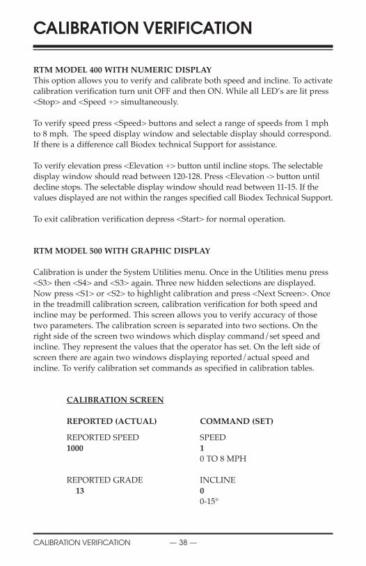
RTM MODEL 400 WITH NUMERIC DISPLAYThis option allows you to verify and calibrate both speed and incline. To activate
calibration verification turn unit OFF and then ON. While all LED’s are lit press
<Stop> and <Speed +> simultaneously.
To verify speed press <Speed> buttons and select a range of speeds from 1 mph
to 8 mph. The speed display window and selectable display should correspond.
If there is a difference call Biodex technical Support for assistance.
To verify elevation press <Elevation +> button until incline stops. The selectable
display window should read between 120-128. Press <Elevation -> button until
decline stops. The selectable display window should read between 11-15. If the
values displayed are not within the ranges specified call Biodex Technical Support.
To exit calibration verification depress <Start> for normal operation.
RTM MODEL 500 WITH GRAPHIC DISPLAY
Calibration is under the System Utilities menu. Once in the Utilities menu press
<S3> then <S4> and <S3> again. Three new hidden selections are displayed.
Now press <S1> or <S2> to highlight calibration and press <Next Screen>. Once
in the treadmill calibration screen, calibration verification for both speed and
incline may be performed. This screen allows you to verify accuracy of those
two parameters. The calibration screen is separated into two sections. On the
right side of the screen two windows which display command/set speed and
incline. They represent the values that the operator has set. On the left side of
screen there are again two windows displaying reported/actual speed and
incline. To verify calibration set commands as specified in calibration tables.
CALIBRATION SCREEN
REPORTED (ACTUAL) COMMAND (SET)
REPORTED SPEED SPEED
1000 10 TO 8 MPH
REPORTED GRADE INCLINE
13 00-15°
CALIBRATION VERIFICATION
CALIBRATION VERIFICATION — 38 —
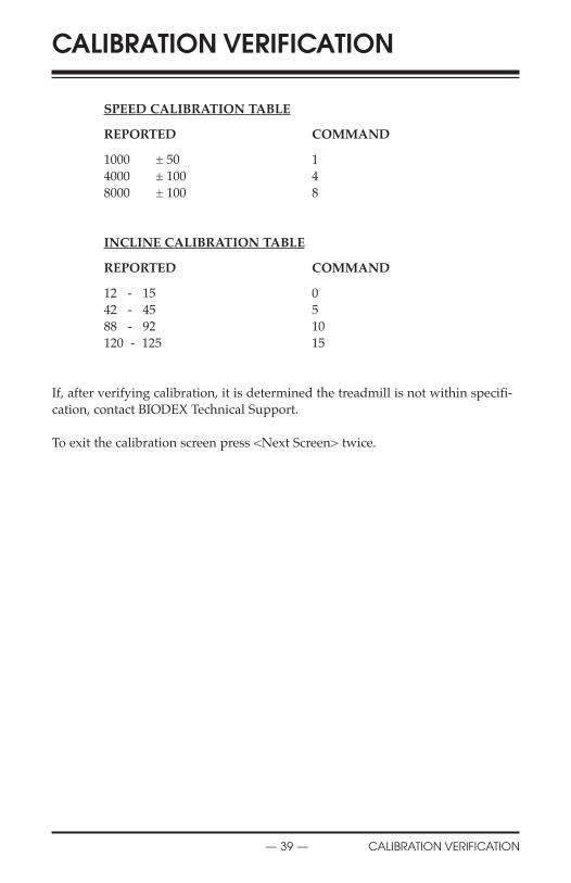
SPEED CALIBRATION TABLE
REPORTED COMMAND
1000 ± 50 1
4000 ± 100 4
8000 ± 100 8
INCLINE CALIBRATION TABLE
REPORTED COMMAND
12 - 15 0
42 - 45 5
88 - 92 10
120 - 125 15
If, after verifying calibration, it is determined the treadmill is not within specifi-
cation, contact BIODEX Technical Support.
To exit the calibration screen press <Next Screen> twice.
CALIBRATION VERIFICATION
— 39 — CALIBRATION VERIFICATION

INSTALLING THE ARM REST PADS (See to Figure 9.)1. Using the supplied 3/16” allen wrench, secure one Arm Rest Receiving
Tubes to each guard rail so that the tube is flush mounted against the front
of the guardrail. Ensure that the pull pin for each receiving tube faces out
(away) from the treadbelt and tighten snugly but not completely.
2. Pull out on the pull pin and slide the arm support pad into the receiving
tube (the arm pads are interchangeable.) Insert the arm pad to the half-way
point and release the pull pin, ensuring that the pin locks in one of the arm
pad support bar detentes.
3. Ensure the arm pad is positioned perpendicular to the floor. Once satisfied
with the arm pad positioning, fully tighten the four allen screws. The arm
pads are now ready for use and should be adjusted as per patient protocol.
INSTALLING THE ELEVATION ROCKERS (See Figure 10.)The RTM Model 500 treadmill is available with Incline/Decline of either stan-
dard 0 to 15 degrees or optional -3 to 12 degrees (Part# 945-275-M315). This set-
ting is preset at the factory prior to shipping.
AvErTissmENT: Cette installation nécessite au moins deux personnes en bonnesanté.
CAUTiON: This procedure requires the efforts of at least two strong individuals.
1. Press <STANDBY> to turn the treadmill to the Standby mode. Turn the
Power Switch, located at the base of the treadmill in the left corner at the
display end, to the “0” (OFF) position. Unplug the treadmill.
2. With the aid of a second person, gently tip the treadmill over on one side.
3. Using a 7/16” wrench, remove the two bolts that secure each rocker to the
treadmill frame.
4. Replace the existing rockers with the new rockers, replace the bolts and
tighten until fully secure.
5. With the aid of a second person, rotate the treadmill back to the upright
position.
6. Press <ON/STANDBY> to turn the treadmill ON. The
Performance/Control screen should appear on the display.
7. Press <Next Screen>. The Main Menu screen should be displayed.
8. Use the <S1> or <S2> key to highlight “System Utilities” and then press
<Next Screen>. The System Utilities Menu should now be displayed.
9. Use the <S1> or <S2> key to highlight “Configure” and then press <Next
Screen>. The Configure Menu should now be displayed.
10. From the Configure Menu, use the <S1> or <S2> key to highlight “Incline
Setting”. Now use the <S3> or <S4> key to select the appropriate elevation
format.
INSTALLATION OF OPTIONAL ARMRESTS & ELEVATION ROCKERS
INSTALLATION OF OPTIONAL ARM… — 40 —
!
!

11. Press <Next Screen> to return to the System Utilities Menu.
12. Highlight “Return to Main Menu” and press <Next Screen> to return to the
Main Menu.
13. Highlight “Exercise” and press <Next Screen> to return to the Exercise
Menu.
14. Press <Next Screen> to return to the Performance/Control screen. The sys-
tem should now be ready for use.
Figure 9. Installing the Arm Rest Pads.
Figure 10. Installing the optional Elevation Rockers.
INSTALLATION OF OPTIONAL ARMRESTS & ELEVATION ROCKERS
— 41 — INSTALLATION OF OPTIONAL ARM…

Item Number DescriptionELECTRICAL945-200-E350 Pwm Motor Controller (RTM)
945-250-E700 Treadmill Chassis Harness
945-275-E700 Display Cable Assembly
945-250-E702 115 Volt Actuator Assembly
945-250-E733 Power Cord, Euro
945-250-E703 Power Cord Assembly
945-250-E704 Hall Effects Cable Assembly
945-250-E708 Pulse Width Mod. Cable
945-250-E709 Lanyard Reed Switch Cable
945-250-E711 Position Potentiometer Assy
945-250-E712 Drive Motor with Tach (w/o flywheel)
945-275-E825 Hall Effects PC Board Assy
945-275-E101 Membrane Switch Overlay (LED)
945-300-E702 Membrane Switch Overlay (LCD)
MECHANICALC08304 Isolation Transformer
C09456 Relay, Solid State (IEC)
C09102 Circuit Breaker Assy
C09001 Magnetic Sensor
C08986 Poly-V Belt “Type J”
C08992 1 x 2” Dia. Wheels
C08983 Vibration Mounts
945-250-M041 Treadmill Belt
945-250-M036 Bed “Double Groove”
945-275-M314 Rear Foot Brackets
945-275-P058 Enclosure Housing RTM Model 400
ASSEMBLIES945-275-A010 Front Roller Assembly
945-275-A020 Rear Roller Assembly
945-250-A090 Safety Lanyard Assembly
945-275-A320 Drive Motor/Flywheel Assembly
945-275-A700 Display, Assy, RTM 400
945-250-A700 Display, Assy, RTM 500
945-250-A720 Control PC Board Assembly
REPLACEMENT PARTS LIST
REPLACEMENT PARTS LIST — 42 —
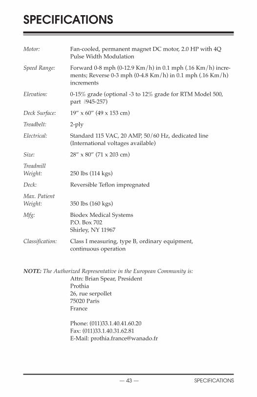
Motor: Fan-cooled, permanent magnet DC motor, 2.0 HP with 4Q
Pulse Width Modulation
Speed Range: Forward 0-8 mph (0-12.9 Km/h) in 0.1 mph (.16 Km/h) incre-
ments; Reverse 0-3 mph (0-4.8 Km/h) in 0.1 mph (.16 Km/h)
increments
Elevation: 0-15% grade (optional -3 to 12% grade for RTM Model 500,
part #945-257)
Deck Surface: 19” x 60” (49 x 153 cm)
Treadbelt: 2-ply
Electrical: Standard 115 VAC, 20 AMP, 50/60 Hz, dedicated line
(International voltages available)
Size: 28” x 80” (71 x 203 cm)
TreadmillWeight: 250 lbs (114 kgs)
Deck: Reversible Teflon impregnated
Max. PatientWeight: 350 lbs (160 kgs)
Mfg: Biodex Medical Systems
P.O. Box 702
Shirley, NY 11967
Classification: Class I measuring, type B, ordinary equipment,
continuous operation
NOTE: The Authorized Representative in the European Community is:Attn: Brian Spear, President
Prothia
26, rue serpollet
75020 Paris
France
Phone: (011)33.1.40.41.60.20
Fax: (011)33.1.40.31.62.81
E-Mail: [email protected]
SPECIFICATIONS
— 43 — SPECIFICATIONS
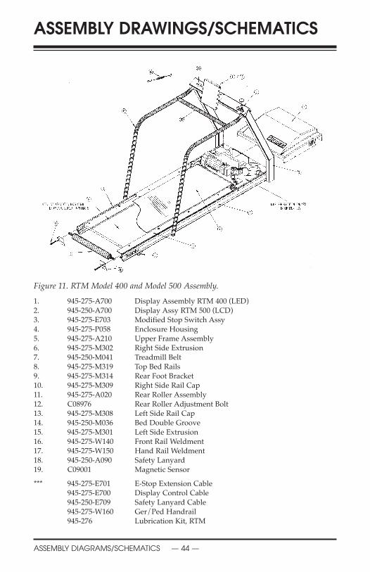
Figure 11. RTM Model 400 and Model 500 Assembly.
1. 945-275-A700 Display Assembly RTM 400 (LED)2. 945-250-A700 Display Assy RTM 500 (LCD)3. 945-275-E703 Modified Stop Switch Assy4. 945-275-P058 Enclosure Housing 5. 945-275-A210 Upper Frame Assembly6. 945-275-M302 Right Side Extrusion7. 945-250-M041 Treadmill Belt8. 945-275-M319 Top Bed Rails9. 945-275-M314 Rear Foot Bracket10. 945-275-M309 Right Side Rail Cap11. 945-275-A020 Rear Roller Assembly12. C08976 Rear Roller Adjustment Bolt13. 945-275-M308 Left Side Rail Cap14. 945-250-M036 Bed Double Groove15. 945-275-M301 Left Side Extrusion16. 945-275-W140 Front Rail Weldment17. 945-275-W150 Hand Rail Weldment18. 945-250-A090 Safety Lanyard19. C09001 Magnetic Sensor
*** 945-275-E701 E-Stop Extension Cable945-275-E700 Display Control Cable945-250-E709 Safety Lanyard Cable945-275-W160 Ger/Ped Handrail945-276 Lubrication Kit, RTM
ASSEMBLY DRAWINGS/SCHEMATICS
ASSEMBLY DIAGRAMS/SCHEMATICS — 44 —

Figure 12. RTM Model 400 and Model 500 Electronic Pan Assembly.
1. 945-275-E350 PWM Motor Controller (RTM)2. 945-250-A720 Control PC Board Assy, RTM III3. 945-250-M091 Actuator Strap4. 945-250-M254 Lift Pivot Bolt5. C09449 Nylon Actuator Nut6. C08905 Modular Cable Coupler, RJ457. 945-2850-E702 115V A/C Actuator Assy 8. 945-250-E711 Position Potentiometer Cable9. 945-250-W180 Potentiometer Lever Weldment
C08912 Screw, Cup Pt. Set, 8-32 x .1210. C08992 2.0 Diameter Wheel11. C08993 Clevis Pin12. C08424 Cotter Pin13. 945-275-W130 Pivot Frame Weldment14. 945-275-A010 Front Roller Assy15. 945-275-M307 Lift Pivot Bracket16. C08991 Nyliner Bearing17. 945-275-E825 Hall Effect Senor PC Bd.18. 945-385-A320 Drive Motor/Flywheel Assy19. C08986 Polt V Belt20. C08304 Isolation Transformer 1KVA21. C09102 Circuit Breaker, Snap-In, 15 amp22. C09456 Relay, Solid State (IEC)
** 945-250-E700 Treadmill Chassis Harness** 945-250-E704 Hall Effect Cable** 945-250-E708 Pulse Width Modulator Cable** 945-275-E702 Communication Ext. Cable
ASSEMBLY DRAWINGS/SCHEMATICS
— 45 — ASSEMBLY DIAGRAMS/SCHEMATICS

Figure 13. RTM Model 400 and Model 500 Schematic Illustration.
ASSEMBLY DRAWINGS/SCHEMATICS
ASSEMBLY DIAGRAMS/SCHEMATICS — 46 —
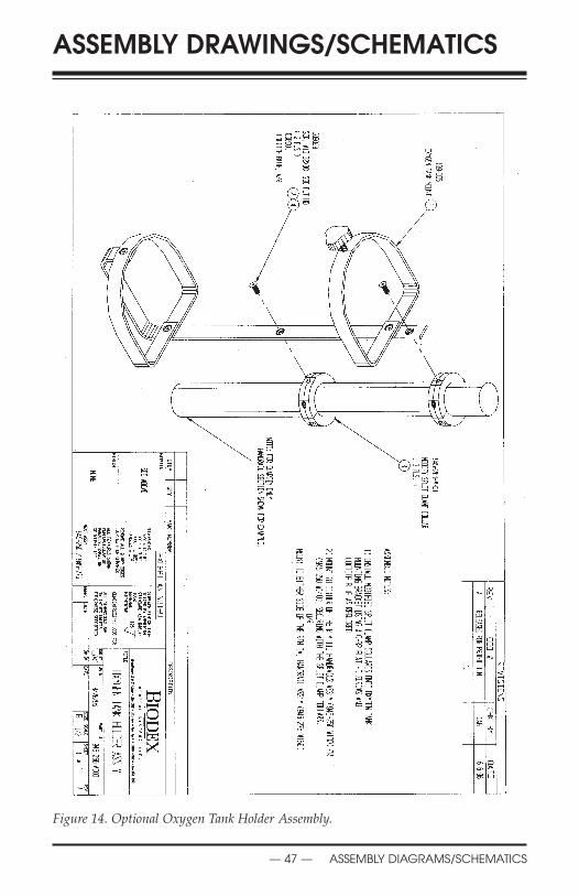
Figure 14. Optional Oxygen Tank Holder Assembly.
ASSEMBLY DRAWINGS/SCHEMATICS
— 47 — ASSEMBLY DIAGRAMS/SCHEMATICS

FN: 02-200 6/02
BIODEXBiodex Medical Systems, Inc.
20 Ramsay Road, Shirley, New York, 11967-0702 Tel: 800-224-6339 (In NY Call 631-924-9000), Fax: 631-924-9338
Email: [email protected], www.biodex.com