Embed Size (px)
Citation preview
The Best Quality of Air Treatment
Save the world with
The Best Quality of Air Treatment
2
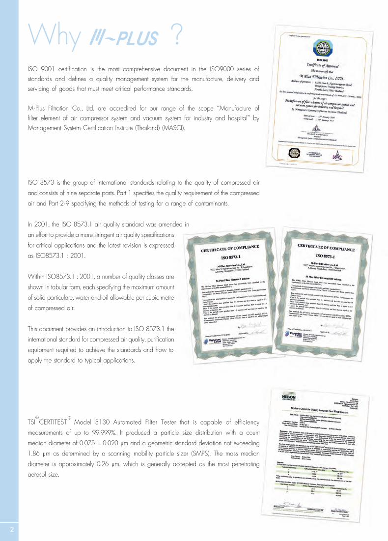
ISO 9001 certifif ication is the most comprehensive document in the ISO9000 series of standards and defif ines a quality management system for the manufacture, delivery and servicing of goods that must meet critical performance standards.
M-Plus Filtration Co., Ltd. are accredited for our range of the scope “Manufacture of f ilter element of air compressor system and vacuum system for industry and hospital” by Management System Certifif ication Institute (Thailand) (MASCI).
ISO 8573 is the group of international standards relating to the quality of compressed air and consists of nine separate parts. Part 1 specifif ies the quality requirement of the compressedair and Part 2-9 specifying the methods of testing for a range of contaminants.
In 2001, the ISO 8573.1 air quality standard was amended inan effort to provide a more stringent air quality specifif ications for critical applications and the latest revision is expressedas ISO8573.1 : 2001.
Within ISO8573.1 : 2001, a number of quality classes areshown in tabular form, each specifying the maximum amountof solid particulate, water and oil allowable per cubic metreof compressed air.
This document provides an introduction to ISO 8573.1 the international standard for compressed air quality, purifif ication equipment required to achieve the standards and how to apply the standard to typical applications.
TSI CERTITEST Model 8130 Automated Filter Tester that is capable of efficiency measurements of up to 99.999%. It produced a particle size distribution with a count median diameter of 0.075 + 0.020 µµm and a geometric standard deviation not exceeding 1.86 µµm as determined by a scanning mobility particle sizer (SMPS). The mass median diameter is approximately 0.26 µµµÂµµm, which is generally accepted as the most penetrating aerosol size.
R R
Why ?
3
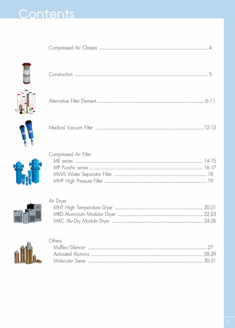
Compressed Air Classes ....................................................................................................... 4
Construction .............................................................................................................................. 5
Alternative Filter Element .......................................................................................................6-11
Medical Vacuum Filter .......................................................................................................12-13
Compressed Air Filter ME series ......................................................................................................................... 14-15 MP PureAir series ............................................................................................................ 16-17 MWS Water Separator Filter ........................................................................................18 MHP High Pressure Filter .................................................................................................19
Air Dryer MHT High Temperature Dryer ................................................................................... 20-21 MRD Aluminium Modular Dryer ................................................................................. 22-23 MAC Alu-Dry Module Dryer ...................................................................................... 24-26
Others Mufflf ler/Silencer .................................................................................................................27 Activated Alumina .......................................................................................................... 28-29 Molecular Sieve ............................................................................................................. 30-31
Contents
4
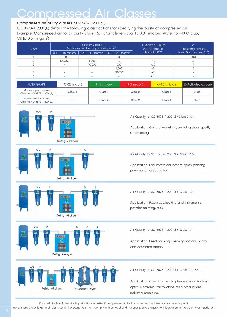
Compressed Air ClassesCompressed air purity classes ISO8573-1:2001(E)ISO 8573-1:2001(E) details the following classifications for specifying the purity of compressed air.Example: Compressed air to air purity class 1.2.1 (Particle removal to 0.01 micron. Water to -40oC pdp, Oil to 0.01 mg/m3)
Air Quality to ISO 8573-1:2001(E),Class 3.4.4
Application: General workshop, servicing shop, quality sandblasting
Air Quality to ISO 8573-1:2001(E),Class 2.4.3
Application: Pneumatic equipment, spray painting, pneumatic transportation
Air Quality to ISO 8573-1:2001(E), Class 1.4.1
Application: Packing, checking and instruments, powder painting, tools
Air Quality to ISO 8573-1:2001(E), Class 1.4.1
Application: Feed packing, weaving factory, photo and cosmetics factory
Air Quality to ISO 8573-1:2001(E), Class 1.(1,2,3).1
Application: Chemical plants, pharmaceutic factory, optic, electronic, micro-chips, feed productions, industrial medicine.
For medicinal and chemical applications is better if compressed air tank is protected by internal anticorrosive paint.Note: These are only general rules. User of the equipment must comply with all local and national pressure equipment legislation in the country of installation.
CLASSSOLID PARTICLES
Maximum number of particles per m3 HUMIDITY & LIQUID WATER pressuredewpoint 0oC
OIL(including aerosol,
liquid & vapour mg/m3)0.1 – 0.5 micron 0.5 – 1.0 micron 1.0 – 5.0 micron1 100 1 0 -70 0.012 100,000 1,000 10 -40 0.13 - 10,000 500 -20 14 - - 1,000 +3 55 - - 20,000 +7 -6 - - - +10 -
FILTER GRADE Q (25 micron) P (5 micron) S (1 micron) X (0.01 micron) Z (Activated carbon)
Maximim particle sizeClass to ISO 8573-1:2001(E) Class 4 Class 3 Class 2 Class 1 Class 1
Maximum oil contentClass to ISO 8573-1:2001(E) - Class 4 Class 2 Class 1 Class 1
5
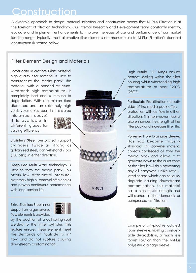
A dynamic approach to design, material selection and construction means that M-Plus Filtration is at the forefront of filtration technology. Our internal Research and Development team constantly identify, evaluate and implement enhancements to improve the ease of use and performance of our market leading range. Typically, most alternative filter elements are manufacture to M Plus Filtration’s standard construction illustrated below.
Filter Element Design and Materials
Construction
Borosilicate Microfibre Glass Material high quality filter material is used to manufacture the media pack. This material, with a bonded structure, withstands high temperatures, is completely inert and is immune to degradation. With sub micron fibre diameters and an extremely high voids volume (as seen in this stereo micro-scan above) it is avai lable in different grades for varying efficiency.
Stainless Steel perforated support cy l inder s , tw ice as s t rong as galvanized steel, can withstand 7 bar (100 psig) in either direction.
Deep Bed Multi Wrap technology is used to form the media pack. This offers low differential pressure, extremely high oil removal efficiencies and proven continuous performance with long service life.
Extra Stainless Steel inner support on larger reverse flow elements is provided by the addition of a coil spring spot welded to the inner cylinder. This feature ensures these element meet the demands of “outside to in” flow and do not rupture causing downstream contamination.
High Nitrile “O” Rings ensure perfect sealing within the filter housing whilst withstanding high temperatures of over 120oC (250oF).
Particulate Pre-filtration on both sides of the media pack offers protection with air flow in either direction. This non-woven fabric also enhances the strength of the filter pack and increases filter life.
Polyester Fibre Drainage Sleeve, Has now become indust ry standard. This polyester material collects coalesced oil from the media pack and allows it to gravitate down to the quiet zone of the filter bowl thus preventing any oil carryover. Unlike reticu-lated foams which can seriously degrade causing downstream contamination, this material has a high tensile strength and withstands all the demands of compressed air filtration.
Example of a typical reticulated foam sleeve exhibiting consider-able degradation, a much less robust solution than the M-Plus polyester drainage sleeve.
6
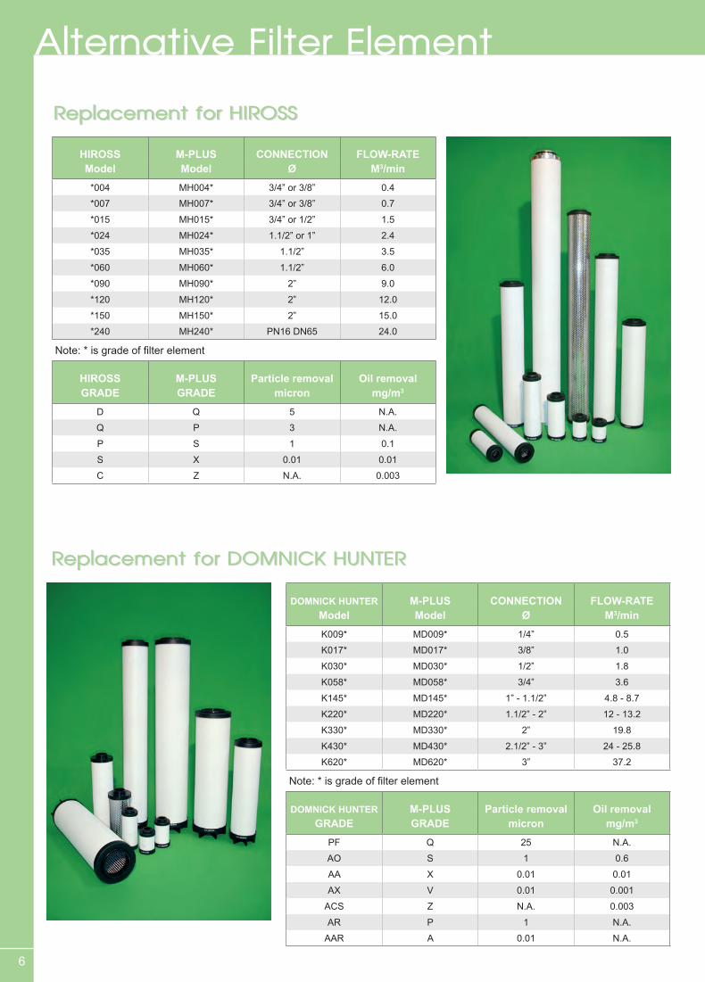
Replacement for HIROSSReplacement for HIROSS
Replacement for DOMNICK HUNTERReplacement for DOMNICK HUNTER
HIROSS M-PLUS CONNECTION FLOW-RATEModel Model Ø M3/min
*004 MH004* 3/4” or 3/8” 0.4
*007 MH007* 3/4” or 3/8” 0.7
*015 MH015* 3/4” or 1/2” 1.5
*024 MH024* 1.1/2” or 1” 2.4
*035 MH035* 1.1/2” 3.5
*060 MH060* 1.1/2” 6.0
*090 MH090* 2” 9.0
*120 MH120* 2” 12.0
*150 MH150* 2” 15.0
*240 MH240* PN16 DN65 24.0
Note: * is grade of filter element
HIROSS M-PLUS Particle removal Oil removalGRADE GRADE micron mg/m3
D Q 5 N.A.
Q P 3 N.A.
P S 1 0.1
S X 0.01 0.01
C Z N.A. 0.003
DOMNICK HUNTER M-PLUS CONNECTION FLOW-RATEModel Model Ø M3/min
K009* MD009* 1/4” 0.5
K017* MD017* 3/8” 1.0
K030* MD030* 1/2” 1.8
K058* MD058* 3/4” 3.6
K145* MD145* 1” - 1.1/2” 4.8 - 8.7
K220* MD220* 1.1/2” - 2” 12 - 13.2
K330* MD330* 2” 19.8
K430* MD430* 2.1/2” - 3” 24 - 25.8
K620* MD620* 3” 37.2
Note: * is grade of filter element
DOMNICK HUNTER M-PLUS Particle removal Oil removalGRADE GRADE micron mg/m3
PF Q 25 N.A.
AO S 1 0.6
AA X 0.01 0.01
AX V 0.01 0.001
ACS Z N.A. 0.003
AR P 1 N.A.
AAR A 0.01 N.A.
Alternative Filter Element
7
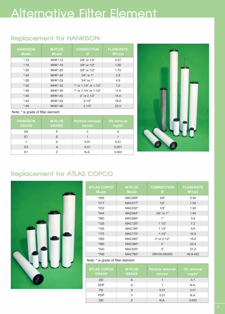
Replacement for ATLAS COPCOReplacement for ATLAS COPCO
Replacement for HANKISONReplacement for HANKISONHANKISON M-PLUS CONNECTION FLOW-RATE
Model Model Ø M3/min
*-12 MHK*-12 3/8” or 1/2” 0.57
*-16 MHK*-16 3/8” or 1/2” 1.00
*-20 MHK*-20 3/8” or 1/2” 1.75
*-24 MHK*-24 3/4” or 1” 2.9
*-28 MHK*-28 3/4” or 1” 4.9
*-32 MHK*-32 1” or 1.1/4” or 1.1/2” 7.2
*-36 MHK*-36 1” or 1.1/4” or 1.1/2” 11.0
*-40 MHK*-40 2” or 2.1/2” 14.0
*-44 MHK*-44 2.1/2” 18.0
*-48 MHK*-48 2.1/2” 22.0
Note: * is grade of filter element
HANKISON M-PLUS Particle removal Oil removalGRADE GRADE micron mg/m3
E9 P 3 5
E7 S 1 1
1 X 0.01 0.01
E3 A 0.01 0.001
E1 Z N.A. 0.003
ATLAS COPCO M-PLUS CONNECTION FLOW-RATEModel Model Ø M3/min
*009 MAC009* 3/8” 0.54
*017 MAC017* 1/2” 1.02
*032 MAC032* 1/2” 1.92
*044 MAC044* 3/4” or 1” 1.64
*060 MAC060* 1” 3.6
*120 MAC120* 1.1/2” 7.2
*150 MAC150* 1.1/2” 9.0
*175 MAC175* 1.1/2” 10.5
*260 MAC260* 2” or 2.1/2” 16.8
*390 MAC390* 3” 23.4
*520 MAC520* 3” 31.2
*780 MAC780* DN100-DN300 46.8-432
Note: * is grade of filter element
ATLAS COPCO M-PLUS Particle removal Oil removalGRADE GRADE micron mg/m3
DD S 1 0.1
DDP A 1 N.A.
PD X 0.01 0.01
PDP V 0.01 N.A.
QD Z N.A. 0.003
Alternative Filter Element

8
Replacement for ORIONReplacement for ORION
Replacement for ULTRA FILTERReplacement for ULTRA FILTER
ULTRA FILTER M-PLUS CONNECTION FLOW-RATEModel Model Ø M3/min
*02/05 MU*02/05 1/4” 0.3
*03/05 MU*03/05 3/8” 0.6
*03/10 MU*03/10 3/8” 1.0
*04/10 MU*04/10 1/2” 1.5
*04/20 MU*04/20 1/2” 2.0
*05/20 MU*05/20 3/4” 3.0
*05/25 MU*05/25 1” 4.5
*07/25 MU*07/25 1.1/4” 6.0
*07/30 MU*07/30 1.1/2” 8.0
*10/30 MU*10/30 2” 12.0
*15/30 MU*15/30 2” 18.0
*20/30 MU*20/30 2.1/2” 24.0
*30/30 MU*30/30 3” 32.0
*30/50 MU*30/50 3” 48.0
Note: * is grade of filter element
ULTRA FILTER M-PLUS Particle removal Oil removalGRADE GRADE micron mg/m3
PE Q 25 N.A.
SB P 5 N.A.
FF S 0.01 0.1
MF A 0.01 0.03
SMF X 0.01 0.01
AK Z N.A. 0.003
ORION M-PLUS CONNECTION FLOW-RATEModel Model Ø M3/min
*400-C MO*400 C 1” 3.9
*700-C MO*700 C 1.1/2” 6.6
*1000-A MO*1000 C 1.1/2” 10.6
*1500-B MO*1500 C 2” 13.8
Note: * is grade of filter element
ORION M-PLUS Particle removal Oil removalGRADE GRADE micron mg/m3
EL S 1 N.A.
EM X 0.01 0.1
EK Z N.A. 0.003
Alternative Filter Element

9
Replacement for ORION(NEW)Replacement for ORION(NEW)
Replacement for ZANDERReplacement for ZANDERZANDER M-PLUS CONNECTION FLOW-RATE
Model Model Ø M3/min
1030* MZ1030* 1/4” 0.5
1050* MZ1050* 1/4” 0.8
1070* MZ1070* 3/8” 1.1
1140* MZ1140* 1/2” 1.6
2010* MZ2010* 3/4” 3.0
2020* MZ2020* 1” 5.0
2030* MZ2030* 1.1/2” 7.8
2050* MZ2050* 1.1/2” 11.6
3050* MZ3050* 2” 15.6
3075* MZ3075* 2” 24.1
5060* MZ5060* 2.1/2” 32.3
5075* MZ5075* 3” 40.0
Note: * is grade of filter element
ZANDER M-PLUS Particle removal Oil removalGRADE GRADE micron mg/m3
V P 3 N.A.
Z S 1 0.5
Y A 0.01 0.1
X X 0.01 0.01
A Z N.A. 0.003
ORION (NEW) M-PLUS CONNECTION FLOW-RATEModel Model Ø M3/min
*150B MOR*150 C 3/4” 1.2
*200B MOR*200 C 3/4” 1.8
*250B MOR*250 C 1” 2.7
*400 MOR*400 C 1” 3.9
*700 MOR*700 C 1.1/2” 6.6
*1000 MOR*1000 C 1.1/2” 10.6
*1300 MOR*1300 C 2” 13.8
*2000 MOR*2000 C 2” 20.0
Note: * is grade of filter element
ORION (NEW) M-PLUS Particle removal Oil removalGRADE GRADE micron mg/m3
EDS P 5 N.A.
ELS S 1 0.1
EMS X 0.01 0.1
EKS Z N.A. 0.003
Alternative Filter Element
10
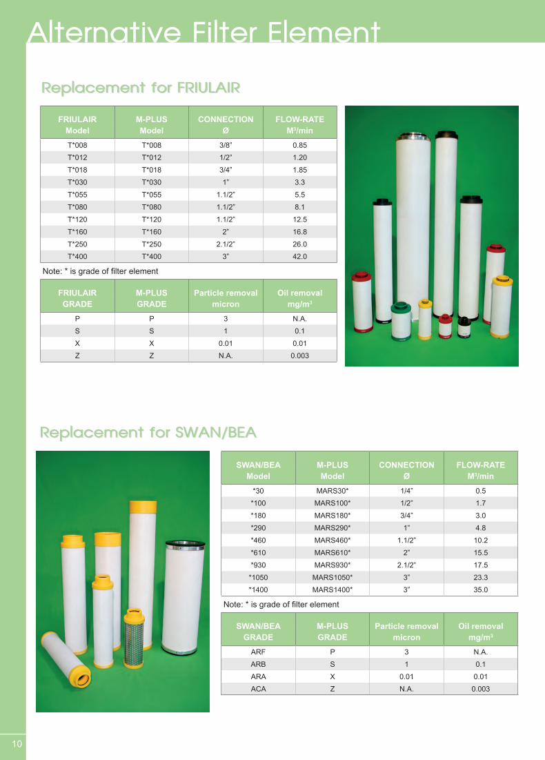
Replacement for SWAN/BEAReplacement for SWAN/BEA
Replacement for FRIULAIRReplacement for FRIULAIR
FRIULAIR M-PLUS CONNECTION FLOW-RATEModel Model Ø M3/min
T*008 T*008 3/8” 0.85
T*012 T*012 1/2” 1.20
T*018 T*018 3/4” 1.85
T*030 T*030 1” 3.3
T*055 T*055 1.1/2” 5.5
T*080 T*080 1.1/2” 8.1
T*120 T*120 1.1/2” 12.5
T*160 T*160 2” 16.8
T*250 T*250 2.1/2” 26.0
T*400 T*400 3” 42.0
Note: * is grade of filter element
FRIULAIR M-PLUS Particle removal Oil removalGRADE GRADE micron mg/m3
P P 3 N.A.
S S 1 0.1
X X 0.01 0.01
Z Z N.A. 0.003
SWAN/BEA M-PLUS CONNECTION FLOW-RATEModel Model Ø M3/min
*30 MARS30* 1/4” 0.5
*100 MARS100* 1/2” 1.7
*180 MARS180* 3/4” 3.0
*290 MARS290* 1” 4.8
*460 MARS460* 1.1/2” 10.2
*610 MARS610* 2” 15.5
*930 MARS930* 2.1/2” 17.5
*1050 MARS1050* 3” 23.3
*1400 MARS1400* 3” 35.0
Note: * is grade of filter element
SWAN/BEA M-PLUS Particle removal Oil removalGRADE GRADE micron mg/m3
ARF P 3 N.A.
ARB S 1 0.1
ARA X 0.01 0.01
ACA Z N.A. 0.003
Alternative Filter Element
11
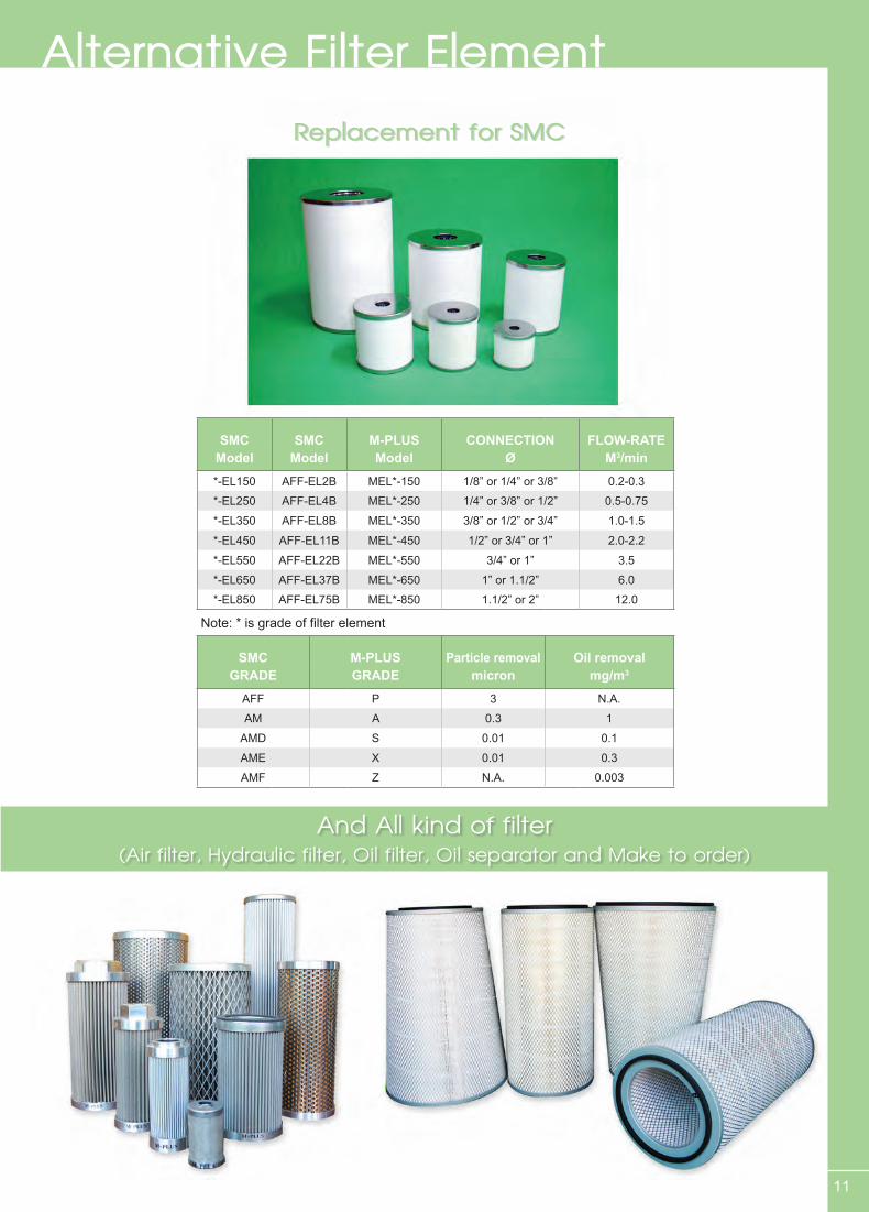
Replacement for SMCReplacement for SMC
Alternative Filter Element
SMC SMC M-PLUS CONNECTION FLOW-RATEModel Model Model Ø M3/min
*-EL150 AFF-EL2B MEL*-150 1/8” or 1/4” or 3/8” 0.2-0.3
*-EL250 AFF-EL4B MEL*-250 1/4” or 3/8” or 1/2” 0.5-0.75
*-EL350 AFF-EL8B MEL*-350 3/8” or 1/2” or 3/4” 1.0-1.5
*-EL450 AFF-EL11B MEL*-450 1/2” or 3/4” or 1” 2.0-2.2
*-EL550 AFF-EL22B MEL*-550 3/4” or 1” 3.5
*-EL650 AFF-EL37B MEL*-650 1” or 1.1/2” 6.0
*-EL850 AFF-EL75B MEL*-850 1.1/2” or 2” 12.0
Note: * is grade of filter element
SMC M-PLUS Particle removal Oil removalGRADE GRADE micron mg/m3
AFF P 3 N.A.
AM A 0.3 1
AMD S 0.01 0.1
AME X 0.01 0.3
AMF Z N.A. 0.003
And All kind of filter (Air filter, Hydraulic filter, Oil filter, Oil separator and Make to order)
12
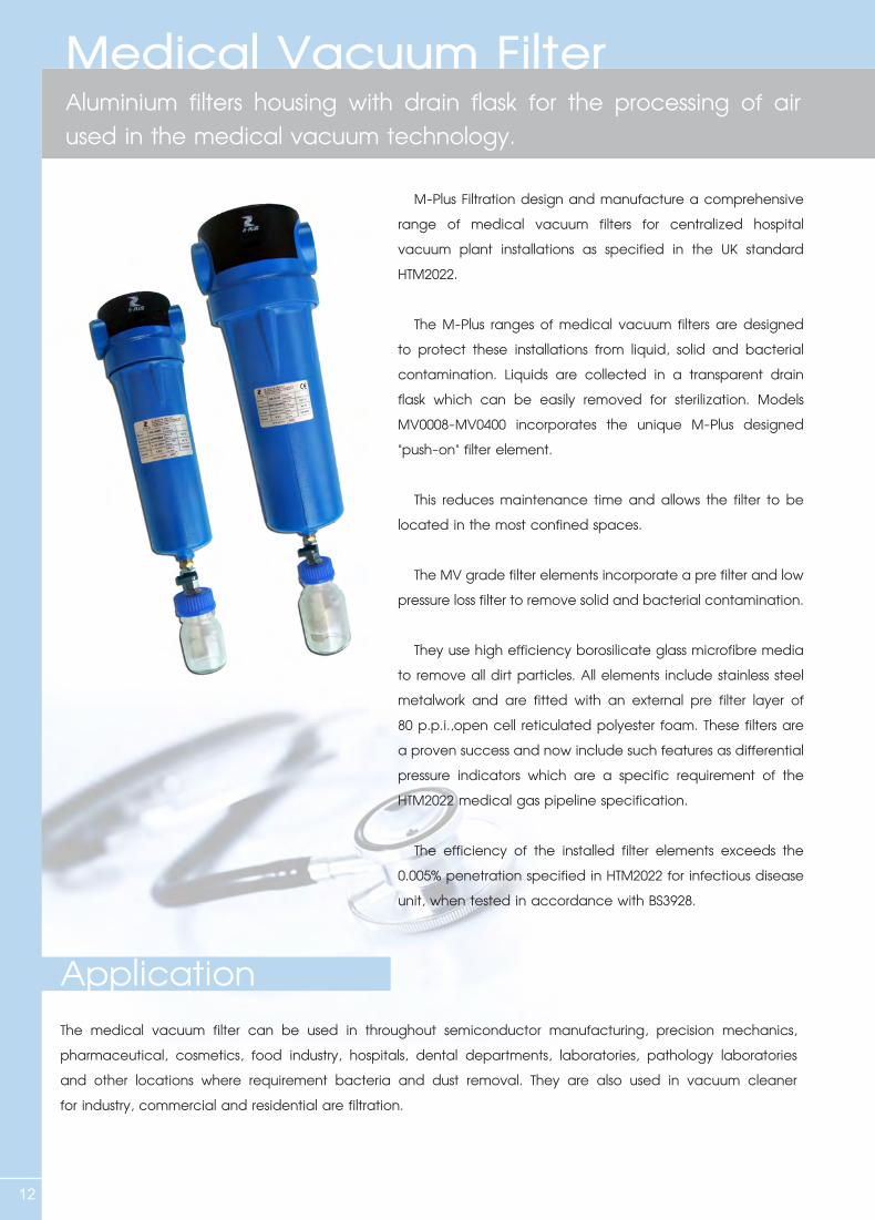
M-Plus Filtration design and manufacture a comprehensive range of medical vacuum filters for centralized hospital vacuum plant installations as specified in the UK standard HTM2022.
The M-Plus ranges of medical vacuum filters are designed to protect these installations from liquid, solid and bacterial contamination. Liquids are collected in a transparent drain flask which can be easily removed for sterilization. Models MV0008-MV0400 incorporates the unique M-Plus designed "push-on" filter element.
This reduces maintenance time and allows the filter to be located in the most confined spaces.
The MV grade filter elements incorporate a pre filter and low pressure loss filter to remove solid and bacterial contamination.
They use high efficiency borosilicate glass microfibre media to remove all dirt particles. All elements include stainless steel metalwork and are fitted with an external pre filter layer of 80 p.p.i.,open cell reticulated polyester foam. These filters are a proven success and now include such features as differential pressure indicators which are a specific requirement of the HTM2022 medical gas pipeline specification.
The efficiency of the installed filter elements exceeds the 0.005% penetration specified in HTM2022 for infectious disease unit, when tested in accordance with BS3928.
ApplicationThe medical vacuum filter can be used in throughout semiconductor manufacturing, precision mechanics, pharmaceutical, cosmetics, food industry, hospitals, dental departments, laboratories, pathology laboratories and other locations where requirement bacteria and dust removal. They are also used in vacuum cleaner for industry, commercial and residential are filtration.
Medical Vacuum FilterAluminium filters housing with drain flask for the processing of air used in the medical vacuum technology.
13
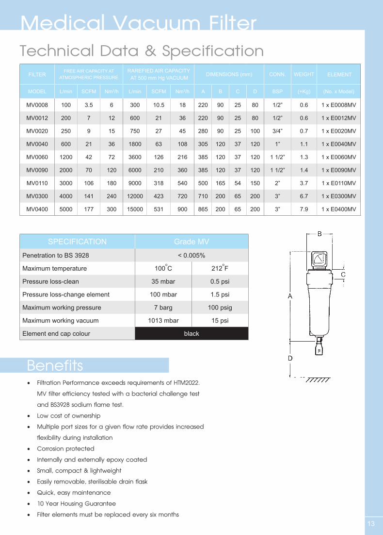
Technical Data & Specification
• FiltrationPerformanceexceedsrequirementsofHTM2022. MV filter efficiency tested with a bacterial challenge test and BS3928 sodium flame test.• Lowcostofownership• Multipleportsizesforagivenflowrateprovidesincreased flexibility during installation• Corrosionprotected• Internallyandexternallyepoxycoated• Small,compact&lightweight• Easilyremovable,sterilisabledrainflask• Quick,easymaintenance• 10YearHousingGuarantee• Filterelementsmustbereplacedeverysixmonths
Benefits
FILTER FREE AIR CAPACITY AT ATMOSPHERIC PRESSURE
RAREFIED AIR CAPACITY AT 500 mm Hg VACUUM
DIMENSIONS (mm) CONN. WEIGHT ELEMENT
MODEL L/min SCFM Nm3/h L/min SCFM Nm3/h A B C D BSP (+Kg) (No. x Model)
MV0008 100 3.5 6 300 10.5 18 220 90 25 80 1/2” 0.6 1 x E0008MV
MV0012 200 7 12 600 21 36 220 90 25 80 1/2” 0.6 1 x E0012MV
MV0020 250 9 15 750 27 45 280 90 25 100 3/4” 0.7 1 x E0020MV
MV0040 600 21 36 1800 63 108 305 120 37 120 1” 1.1 1 x E0040MV
MV0060 1200 42 72 3600 126 216 385 120 37 120 1 1/2” 1.3 1 x E0060MV
MV0090 2000 70 120 6000 210 360 385 120 37 120 1 1/2” 1.4 1 x E0090MV
MV0110 3000 106 180 9000 318 540 500 165 54 150 2” 3.7 1 x E0110MV
MV0300 4000 141 240 12000 423 720 710 200 65 200 3” 6.7 1 x E0300MV
MV0400 5000 177 300 15000 531 900 865 200 65 200 3” 7.9 1 x E0400MV
SPECIFICATION Grade MV
Penetration to BS 3928 < 0.005%
Maximum temperature 100oC 212
oF
Pressure loss-clean 35 mbar 0.5 psi
Pressure loss-change element 100 mbar 1.5 psi
Maximum working pressure 7 barg 100 psig
Maximum working vacuum 1013 mbar 15 psi
Element end cap colour black
Medical Vacuum Filter
14
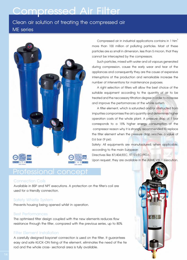
Compressed Air FilterClean air solution of treating the compressed airME series
Compressed air in industrial applications contains in 1 Nm3 more than 100 million of polluting particles. Most of these particles are so small in dimension, less than 5 micron, that they cannot be intercepted by the compressors. Such particles, mixed with water and oil vapours generated during compression, cause the early wear and tear of the appliances and consequently they are the cause of expensive interruptions of the production and remarkable increase the number of interventions for maintenance purposes. A right selection of filters will allow the best choice of the suitable equipment according to the quantity of air to be treated and the neccessary filtration degree in order to increase and improve the performances of the whole system. A filter element, which is saturated and/or obstructed from impurities compromises the air's quantity and determines higher operation costs of the whole plant. A pressure drop of 1 bar corresponds to a 15% higher energy consumption of the compressor reason why it is strongly recommended to replace the filter element when the pressure drop reaches a value of 0.6 bar (9 psi).Safety: All equipments are manufactured, when applicable, according to the main EuropeanDirectives like 87/404/EEC, 97/23/EC(PED).Upon request, they are available in the ASME VIII-1 execution.
Professional conceptConnection CoilsAvailable in BSP and NPT executions. A protection on the filter's coil are used for a friendly connection.
Safety Whistle SystemPrevents housing being opened whilst in operation.
Best PerformancesThe optimised filter design coupled with the new elements reduces flow resistance through the filter, compared with the previous series, up to 80%
Filter Element InstallationA carefully designed bayonet connection is used on the filter. It guarantees easy and safe KLICK-ON fixing of the element, eliminates the need of the tie rod and the whole cross- sectional area is fully available.
C Q P S X Z
15
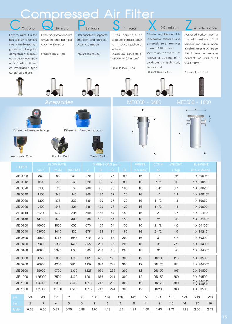
Compressed Air Filter Cyclone
Easy to install it is the best solution to remove the condensat ion generated during the compression process.upon request equipped with floating timed or instellidrain type condensate drains.
25 micron
Filter capable to separate emulsion and particles down to 25 micron
Pressure loss 0.4 psi
3 micron
Filter capable to separate emulsion and particles down to 3 micron
Pressure loss 0.6 psi
1 micron
F i l t e r c a p ab l e t o separate particles down to 1 micron, liquid an oil included.Maximum contents of residual oil 0.1 mg/m3
Pressure loss 1.1 psi
0.01 micron
Oil removing filter capable to separate residual oil and extremely small particles down to 0.01 micron. Maximum contents of residual oil 0.01 mg/m3. It produces air technically free from oil.Pressure loss 1.5 psi
Activated Carbon
Activated carbon filter for the el iminat ion of oi l vapours and odour. When installed, after a (X) grade filter, it lower the maximum contents of residual oil 0.003 mg/m3
Pressure loss 1.1 psi
Acessories ME0008 - 0480 ME0500 - 1800
Differential Pressure Gauge Differential Pressure Indicator
Automatic Drain Floating Drain Timed Drain
FILTER FLOW-RATE DIMENSIONS (mm) PRESS. CONN. WEIGHT ELEMENT
(l/min) (m3/h) (SCFM ) A B C D (bar max) Ø (+Kg) (No. x Model)
ME 0008 880 53 31 220 90 25 80 16 1/2” 0.6 1 X E0008*
ME 0012 1200 72 42 220 90 25 80 16 1/2” 0.6 1 X E0012*
ME 0020 2100 126 74 280 90 25 100 16 3/4” 0.7 1 X E0020*
ME 0040 4100 246 145 305 120 37 120 16 1” 1.1 1 X E0040*
ME 0060 6300 378 222 385 120 37 120 16 1.1/2” 1.3 1 X E0060*
ME 0090 9100 546 321 385 120 37 120 16 1.1/2” 1.4 1 X E0090*
ME 0110 11200 672 395 500 165 54 150 16 2” 3.7 1 X E0110*
ME 0140 14100 846 498 500 165 54 150 16 2” 3.8 1 X E0140*
ME 0180 18000 1080 635 675 165 54 150 16 2.1/2” 4.8 1 X E0180*
ME 0240 23500 1410 830 675 165 54 150 16 2.1/2” 4.9 1 X E0240*
ME 0300 29600 1776 1045 710 200 65 200 16 3” 6.7 1 X E0300*
ME 0400 39800 2388 1405 865 200 65 200 16 3” 7.9 1 X E0400*
ME 0480 48800 2928 1723 985 200 65 200 16 3” 8.6 1 X E0480*
ME 0500 50500 3030 1783 1126 485 195 300 12 DN100 116 1 X E0500*
ME 0700 70000 4200 2800 1137 630 238 300 12 DN125 184 2 X E0400*
ME 0900 95000 5700 3300 1227 630 238 300 12 DN150 197 2 X E0500*
ME 1200 125000 7500 4400 1261 676 241 300 12 DN150 250 3 X E0500*
ME 1500 155000 9300 5400 1316 712 262 300 12 DN175 300 2 X E0400*2 X E0500*
ME 1800 185000 11000 6500 1316 712 274 300 12 DN200 300 4 X E0500*
psi 29 43 57 71 85 100 114 128 142 156 171 185 199 213 228
bar 2 3 4 5 6 7 8 9 10 11 12 13 14 15 16
factor 0.36 0.50 0.63 0.75 0.88 1.00 1.13 1.25 1.38 1.50 1.63 1.75 1.88 2.00 2.13
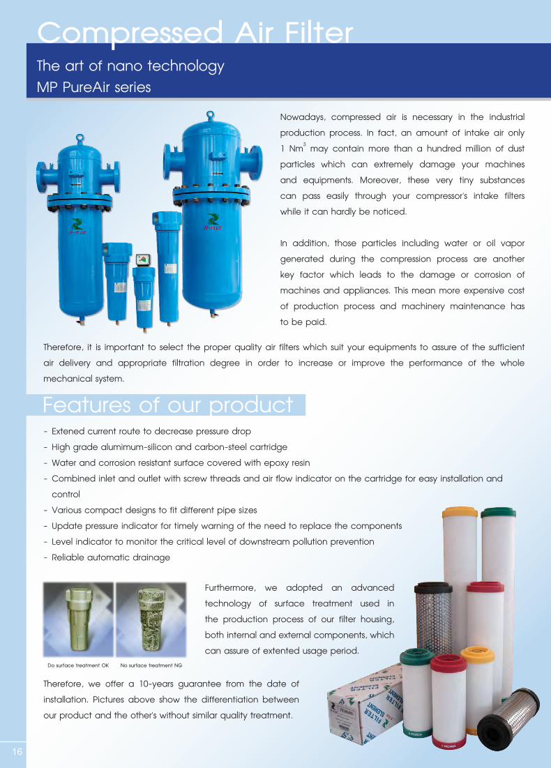
The art of nano technologyMP PureAir series
16
Nowadays, compressed air is necessary in the industrial production process. In fact, an amount of intake air only 1 Nm3 may contain more than a hundred million of dust particles which can extremely damage your machines and equipments. Moreover, these very tiny substances can pass easily through your compressor's intake filters while it can hardly be noticed.
In addition, those particles including water or oil vapor generated during the compression process are another key factor which leads to the damage or corrosion of machines and appliances. This mean more expensive cost of production process and machinery maintenance has to be paid.
Therefore, it is important to select the proper quality air filters which suit your equipments to assure of the sufficient air delivery and appropriate filtration degree in order to increase or improve the performance of the whole mechanical system.
- Extened current route to decrease pressure drop- High grade alumimum-silicon and carbon-steel cartridge- Water and corrosion resistant surface covered with epoxy resin- Combined inlet and outlet with screw threads and air flow indicator on the cartridge for easy installation and control- Various compact designs to fit different pipe sizes- Update pressure indicator for timely warning of the need to replace the components- Level indicator to monitor the critical level of downstream pollution prevention- Reliable automatic drainage
Furthermore, we adopted an advanced technology of surface treatment used in the production process of our filter housing, both internal and external components, which can assure of extented usage period.
Therefore, we offer a 10-years guarantee from the date of installation. Pictures above show the differentiation between our product and the other's without similar quality treatment.
Features of our product
Do surface treatment OK No surface treatment NG
Compressed Air Filter
17
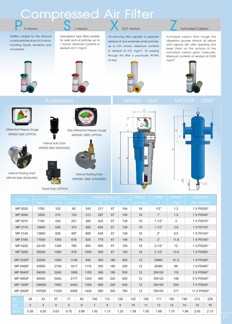
Acessories MP0020 - 0260 MP0330F - 2000F
Differential Pressure GaugeMP0020-0260 (OPTION)
Pipe Differential Pressure GaugeMP0330F-1800F (OPTION)
Internal Auto DrainMP0020-0260 (STANDARD)
External Floating DrainMP0140-0260 (STANDARD)
External Floating DrainMP0330F-1800F (STANDARD)
Timed Drain (OPTION)
P S X ZCompressed Air Filter
3 micron
Prefilter suitable for the removal of solid particles down to 5 micron including liquids, emulsions and oil particles.
1 micron
Interception type filters suitable for solid and oil particles up to 1 micron. Maximum contents of residual oil 0.1 mg/m3.
0.01 micron
Oil removing filter capable to separate residual oil and extremely small particlesup to 0.01 micron. Maximum contents of residual oil 0.01 mg/m3. Air passing through this filter is practically 99.99% oil free.
Activated Carbon
Activated carbon filter trough the absorption process attracts all adours and vapours left after desoiling and keep them on the surface of the activated carbon grain molecules. Maximum contents of residual oil 0.003 mg/m3.
FILTER FLOW-RATE DIMENSIONS (mm) PRESS. CONN. WEIGHT ELEMENT
(l/min) (m3/h) (SCFM ) A B C D (bar max) Ø (+Kg) (No. x Model)
MP 0020 1700 102 60 243 217 67 104 16 1/2” 1.2 1 X P0020*
MP 0040 3500 210 124 313 287 67 104 16 1” 1.5 1 X P0040*
MP 0070 7100 426 251 385 424 67 138 16 1.1/2” 3 1 X P0070*
MP 0110 10600 636 374 585 624 67 138 16 1.1/2” 3.6 1 X P0110*
MP 0140 13800 828 487 685 639 67 148 16 2” 9.5 1 X P0140*
MP 0180 17500 1050 618 825 779 67 148 16 2” 11.8 1 X P0180*
MP 0220 22100 1326 780 850 800 67 150 16 2.1/2” 12 1 X P0220*
MP 0260 26000 1560 918 1000 950 67 150 16 2.1/2” 13.6 1 X P0260*
MP 0330F 32500 1950 1148 940 350 180 300 12 DN65 51.5 1 X P0330*
MP 0460F 45800 2748 1617 1118 355 180 336 12 DN80 86 1 X P0460*
MP 0540F 54000 3240 1906 1150 380 180 500 12 DN100 119 3 X P0540*
MP 0900F 90000 5400 3177 1250 480 220 600 12 DN125 148 5 X P0540*
MP 1300F 126000 7560 4450 1350 560 230 630 12 DN150 204 7 X P0540*
MP 2000F 197000 11820 6958 1400 580 250 780 12 DN150 317 11 X P0540*
psi 29 43 57 71 85 100 114 128 142 156 171 185 199 213 228
bar 2 3 4 5 6 7 8 9 10 11 12 13 14 15 16
factor 0.36 0.50 0.63 0.75 0.88 1.00 1.13 1.25 1.38 1.50 1.68 1.75 1.88 2.00 2.13
18
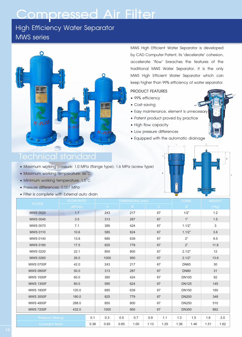
MWS High Efficient Water Separator is developed by CAD Computer Patent, its "decelerate" cohesion, accelerate "flow" breaches the features of the traditional MWS Water Separator, it is the only MWS High Efficient Water Separator which can keep higher than 99% efficiency of water separator.
PRODUCT FEATURES•99%efficiency•Cost-saving•Easy maintenance, element is unnecessary•Patentproductprovedbypractice•Highflowcapacity•Lowpressuredifferences•Equippedwiththeautomaticdrainage
•Maximumworkingpressure:1.0MPa(flangetype);1.6MPa(screwtype)•Maximumworkingtemperature:66oC•Minimumworkingtemperature:1.5oC•Pressuredifferences:0.007MPa•FilteriscompletewithExternalautodrain
High Efficiency Water SeparatorMWS series
Technical standard
FILTER FLOW-RATE DIMENSIONS (mm) CONN. WEIGHT
(M3/min) A B C Ø (+Kg)
MWS 0020 1.7 243 217 67 1/2” 1.2
MWS 0040 3.5 313 287 67 1” 1.5
MWS 0070 7.1 385 424 67 1.1/2” 3
MWS 0110 10.6 585 624 67 1.1/2” 3.6
MWS 0140 13.8 685 639 67 2” 9.5
MWS 0180 17.5 825 779 67 2” 11.8
MWS 0220 22.1 850 800 67 2.1/2” 12
MWS 0260 26.0 1000 950 67 2.1/2” 13.6
MWS 0700F 42.0 243 217 67 DN65 30
MWS 0800F 50.0 313 287 67 DN80 31
MWS 1000F 60.0 385 424 67 DN100 92
MWS 1300F 80.0 585 624 67 DN125 145
MWS 1800F 120.0 685 639 67 DN150 160
MWS 3000F 180.0 825 779 67 DN200 348
MWS 4800F 288.0 850 800 67 DN250 510
MWS 7200F 432.0 1000 950 67 DN300 662
Pressure (Mpa:g) 0.1 0.3 0.5 0.7 0.9 1.1 1.3 1.5 1.6 2.0
Correction factor 0.38 0.65 0.85 1.00 1.13 1.25 1.36 1.46 1.51 1.62
Compressed Air Filter
19
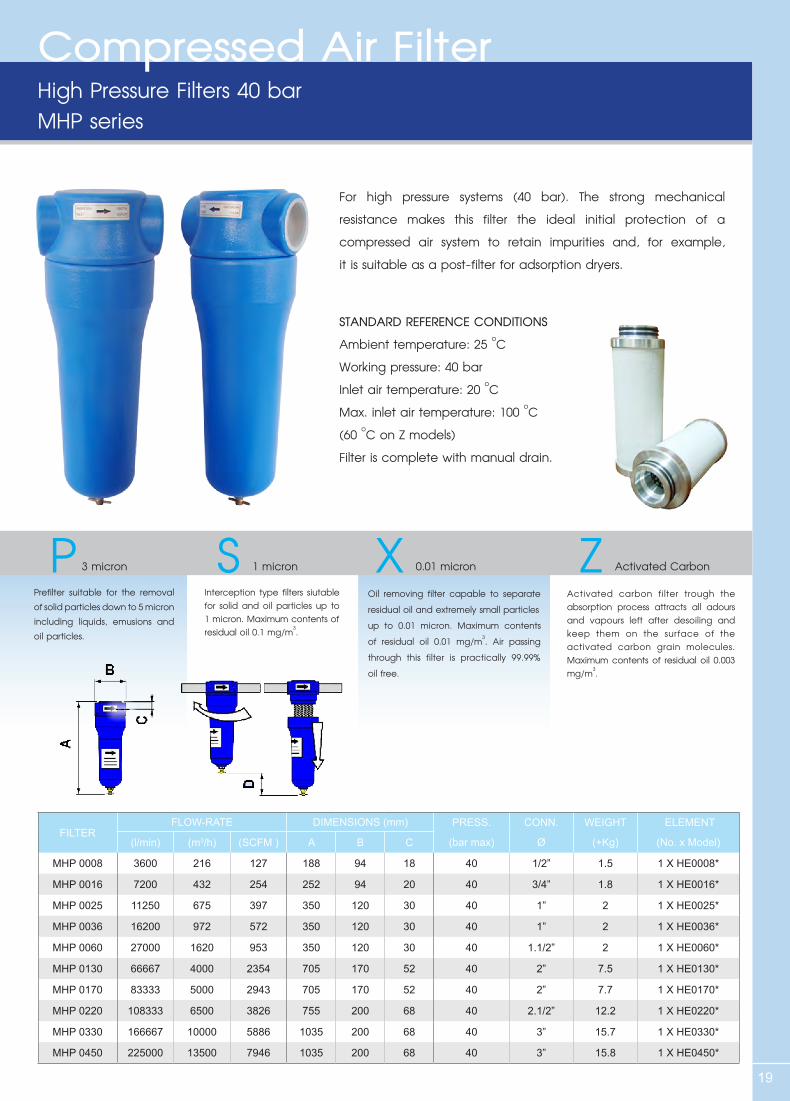
High Pressure Filters 40 barMHP series
For high pressure systems (40 bar). The strong mechanical resistance makes this filter the ideal initial protection of a compressed air system to retain impurities and, for example, it is suitable as a post-filter for adsorption dryers.
STANDARD REFERENCE CONDITIONSAmbient temperature: 25 oCWorking pressure: 40 barInlet air temperature: 20 oCMax. inlet air temperature: 100 oC (60 oC on Z models)Filter is complete with manual drain.
P S X Z 3 micron
Prefilter suitable for the removal of solid particles down to 5 micron including liquids, emusions and oil particles.
1 micron
Interception type filters siutable for solid and oil particles up to 1 micron. Maximum contents of residual oil 0.1 mg/m3.
0.01 micron
Oil removing filter capable to separate residual oil and extremely small particlesup to 0.01 micron. Maximum contents of residual oil 0.01 mg/m3. Air passing through this filter is practically 99.99% oil free.
Activated Carbon
Activated carbon filter trough the absorption process attracts all adours and vapours left after desoiling and keep them on the surface of the activated carbon grain molecules. Maximum contents of residual oil 0.003 mg/m3.
FILTER FLOW-RATE DIMENSIONS (mm) PRESS. CONN. WEIGHT ELEMENT
(l/min) (m3/h) (SCFM ) A B C (bar max) Ø (+Kg) (No. x Model)
MHP 0008 3600 216 127 188 94 18 40 1/2” 1.5 1 X HE0008*
MHP 0016 7200 432 254 252 94 20 40 3/4” 1.8 1 X HE0016*
MHP 0025 11250 675 397 350 120 30 40 1” 2 1 X HE0025*
MHP 0036 16200 972 572 350 120 30 40 1” 2 1 X HE0036*
MHP 0060 27000 1620 953 350 120 30 40 1.1/2” 2 1 X HE0060*
MHP 0130 66667 4000 2354 705 170 52 40 2” 7.5 1 X HE0130*
MHP 0170 83333 5000 2943 705 170 52 40 2” 7.7 1 X HE0170*
MHP 0220 108333 6500 3826 755 200 68 40 2.1/2” 12.2 1 X HE0220*
MHP 0330 166667 10000 5886 1035 200 68 40 3” 15.7 1 X HE0330*
MHP 0450 225000 13500 7946 1035 200 68 40 3” 15.8 1 X HE0450*
Compressed Air Filter
20
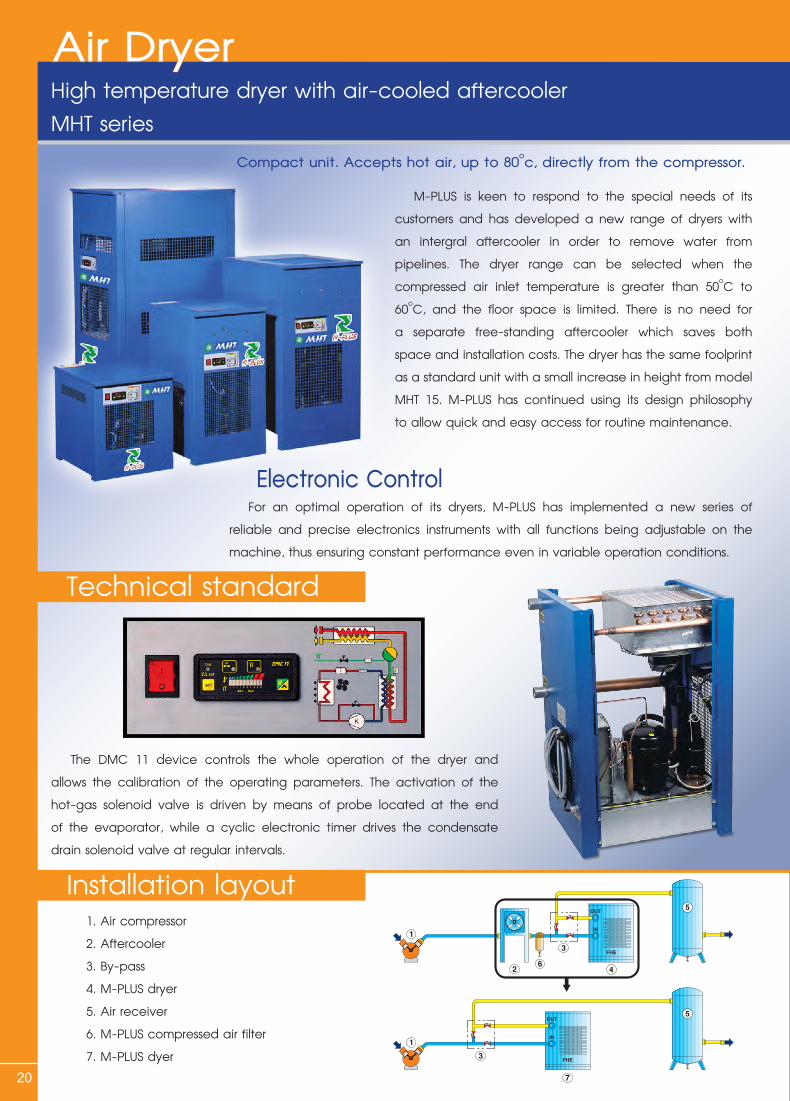
Compact unit. Accepts hot air, up to 80oc, directly from the compressor.
M-PLUS is keen to respond to the special needs of its customers and has developed a new range of dryers with an intergral aftercooler in order to remove water from pipelines. The dryer range can be selected when the compressed air inlet temperature is greater than 50oC to 60oC, and the floor space is limited. There is no need for a separate free-standing aftercooler which saves both space and installation costs. The dryer has the same foolprint as a standard unit with a small increase in height from model MHT 15. M-PLUS has continued using its design philosophy to allow quick and easy access for routine maintenance.
Electronic Control For an optimal operation of its dryers, M-PLUS has implemented a new series of reliable and precise electronics instruments with all functions being adjustable on the machine, thus ensuring constant performance even in variable operation conditions.
The DMC 11 device controls the whole operation of the dryer and allows the calibration of the operating parameters. The activation of the hot-gas solenoid valve is driven by means of probe located at the end of the evaporator, while a cyclic electronic timer drives the condensate drain solenoid valve at regular intervals.
1. Air compressor2. Aftercooler3. By-pass4. M-PLUS dryer5. Air receiver6. M-PLUS compressed air filter7. M-PLUS dyer FHE
FHE
High temperature dryer with air-cooled aftercoolerMHT series
Air Dryer
Technical standard
Installation layout
21
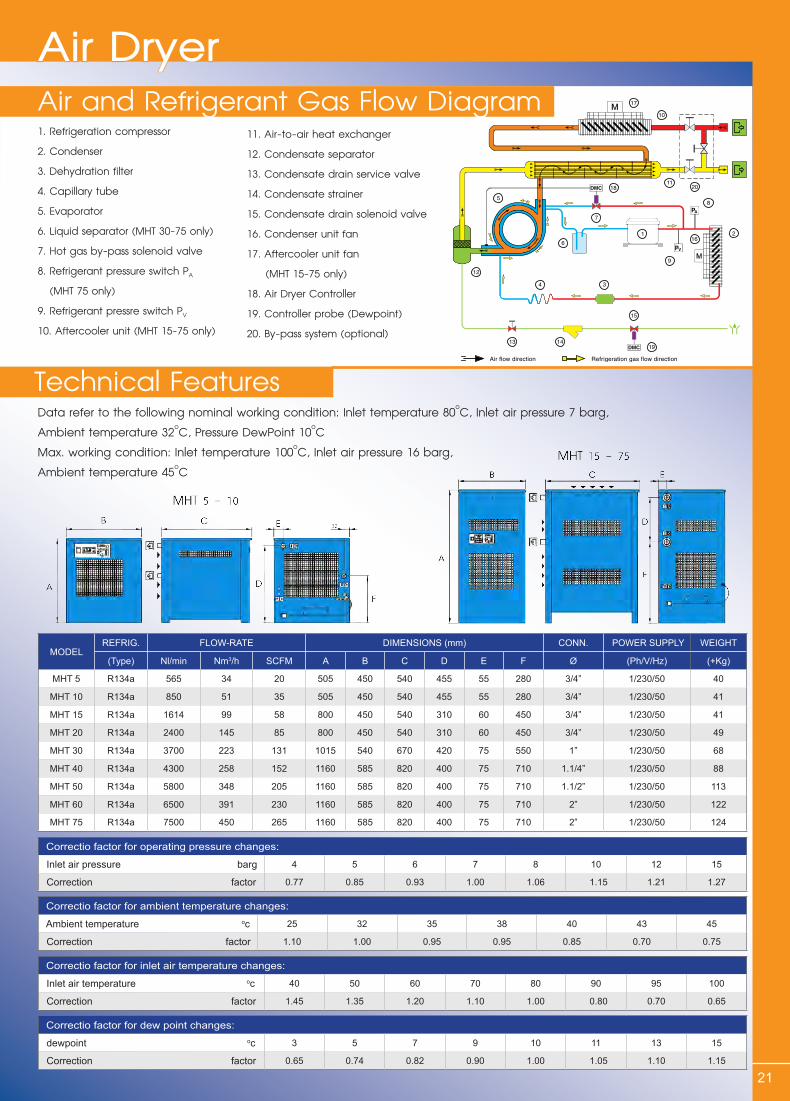
1. Refrigeration compressor2. Condenser3. Dehydration filter4. Capillary tube5. Evaporator6. Liquid separator (MHT 30-75 only)7. Hot gas by-pass solenoid valve8. Refrigerant pressure switch PA (MHT 75 only)9. Refrigerant pressre switch PV
10. Aftercooler unit (MHT 15-75 only)
11. Air-to-air heat exchanger12. Condensate separator13. Condensate drain service valve14. Condensate strainer15. Condensate drain solenoid valve16. Condenser unit fan17. Aftercooler unit fan (MHT 15-75 only)18. Air Dryer Controller19. Controller probe (Dewpoint)20. By-pass system (optional)
Data refer to the following nominal working condition: Inlet temperature 80oC, Inlet air pressure 7 barg, Ambient temperature 32oC, Pressure DewPoint 10oCMax. working condition: Inlet temperature 100oC, Inlet air pressure 16 barg, Ambient temperature 45oC
Air and Refrigerant Gas Flow DiagramAir Dryer
Technical Features
MODELREFRIG. FLOW-RATE DIMENSIONS (mm) CONN. POWER SUPPLY WEIGHT
(Type) Nl/min Nm3/h SCFM A B C D E F Ø (Ph/V/Hz) (+Kg)
MHT 5 R134a 565 34 20 505 450 540 455 55 280 3/4” 1/230/50 40
MHT 10 R134a 850 51 35 505 450 540 455 55 280 3/4” 1/230/50 41
MHT 15 R134a 1614 99 58 800 450 540 310 60 450 3/4” 1/230/50 41
MHT 20 R134a 2400 145 85 800 450 540 310 60 450 3/4” 1/230/50 49
MHT 30 R134a 3700 223 131 1015 540 670 420 75 550 1” 1/230/50 68
MHT 40 R134a 4300 258 152 1160 585 820 400 75 710 1.1/4” 1/230/50 88
MHT 50 R134a 5800 348 205 1160 585 820 400 75 710 1.1/2” 1/230/50 113
MHT 60 R134a 6500 391 230 1160 585 820 400 75 710 2” 1/230/50 122
MHT 75 R134a 7500 450 265 1160 585 820 400 75 710 2” 1/230/50 124
Correctio factor for operating pressure changes:
Inlet air pressure barg 4 5 6 7 8 10 12 15
Correction factor 0.77 0.85 0.93 1.00 1.06 1.15 1.21 1.27
Correctio factor for inlet air temperature changes:
Inlet air temperature oc 40 50 60 70 80 90 95 100
Correction factor 1.45 1.35 1.20 1.10 1.00 0.80 0.70 0.65
Correctio factor for ambient temperature changes:
Ambient temperature oc 25 32 35 38 40 43 45
Correction factor 1.10 1.00 0.95 0.95 0.85 0.70 0.75
Correctio factor for dew point changes:
dewpoint oc 3 5 7 9 10 11 13 15
Correction factor 0.65 0.74 0.82 0.90 1.00 1.05 1.10 1.15
22
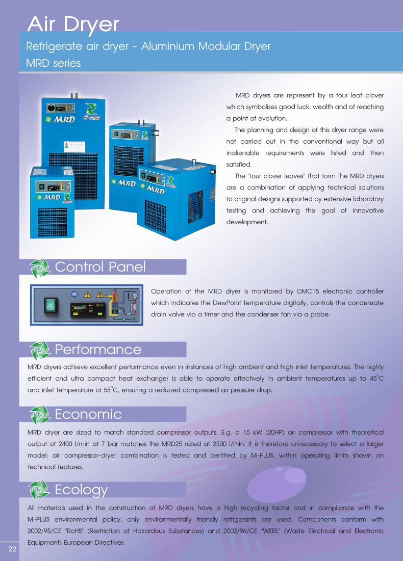
Refrigerate air dryer - Aluminium Modular DryerMRD series
Air Dryer
Economic
Ecology
Performance
Control Panel
MRD dryers are represent by a four leaf clover which symbolises good luck, wealth and of reaching a point of evolution. The planning and design of this dryer range were not carried out in the conventional way but all inalienable requirements were listed and then satisfied. The "four clover leaves" that form the MRD dryers are a combination of applying technical solutions to original designs supported by extensive laboratory testing and achieving the goal of innovative development.
Operation of the MRD dryer is monitored by DMC15 electronic controller which indicates the DewPoint temperature digitally, controls the condensate drain valve via a timer and the condenser fan via a probe.
MRD dryers achieve excellent performance even in instances of high ambient and high inlet temperatures. The highly efficient and ultra compact heat exchanger is able to operate effectively in ambient temperatures up to 45oC and inlet temperature of 55oC, ensuring a reduced compressed air pressure drop.
MRD dryer are sized to match standard compressor outputs. E.g. a 15 kW (20HP) air compressor with theoretical output of 2400 l/min at 7 bar matches the MRD25 rated at 2500 l/min. It is therefore unnecessary to select a larger model: air compressor-dryer combination is tested and certified by M-PLUS, within operating limits shown on technical features.
All materials used in the construction of MRD dryers have a high recycling factor and in compliance with the M-PLUS environmental policy, only environmentally friendly refrigerants are used. Components conform with 2002/95/CE "RoHS" (Restriction of Hazardous Substances) and 2002/96/CE "WEEE" (Waste Electrical and Electronic Equipment) European Directives.
23
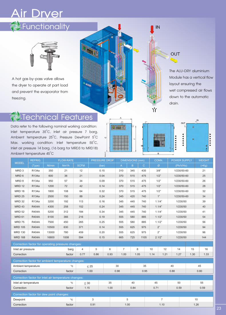
A hot gas by-pass valve allows the dryer to operate at part load and prevent the evaporator from freezing.
The ALU-DRY aluminium Module has a vertical flow layout ensuring the wet compressed air flows down to the automatic drain.
Data refer to the following nominal working condition: Inlet temperature 35oC, Inlet air pressure 7 barg, Ambient temperature 25oC, Pressure DewPoint 5oC Max. working condition: Inlet temperature 55oC, Inlet air pressure 14 barg, (16 barg for MRD3 to MRD18) Ambient temperature 45oC
Technical Features
FunctionalityAir Dryer
MODELREFRIG. FLOW-RATE PRESSURE DROP DIMENSIONS (mm) CONN. POWER SUPPLY WEIGHT
(Type) Nl/min Nm3/h SCFM (bar) A B C Ø (Ph/V/Hz) (+Kg)
MRD 3 R134a 350 21 12 0.15 310 345 435 3/8” 1/230/50-60 21
MRD 6 R134a 600 36 21 0.04 370 515 475 1/2” 1/230/50-60 25
MRD 9 R134a 950 57 34 0.09 370 515 475 1/2” 1/230/50-60 26
MRD 12 R134a 1200 72 42 0.14 370 515 475 1/2” 1/230/50-60 28
MRD 18 R134a 1800 108 64 0.32 370 515 475 1/2” 1/230/50-60 32
MRD 25 R134a 2500 150 88 0.24 345 420 740 1” 1/230/50-60 34
MRD 32 R134a 3200 192 113 0.16 345 445 740 1.1/4” 1/230/50 39
MRD 43 R404A 4300 258 152 0.24 345 445 740 1.1/4” 1/230/50 40
MRD 52 R404A 5200 312 184 0.34 345 445 740 1.1/4” 1/230/50 41
MRD 61 R404A 6100 366 216 0.19 555 580 885 1.1/2” 1/230/50 54
MRD 75 R404A 7500 450 265 0.25 555 580 885 1.1/2” 1/230/50 56
MRD 105 R404A 10500 630 371 0.14 555 625 975 2” 1/230/50 94
MRD 130 R404A 13000 780 459 0.20 555 625 975 2” 1/230/50 96
MRD 168 R404A 16800 1008 594 0.15 665 725 1105 2.1/2” 1/230/50 144
Correction factor for operating pressure changes:
Inlet air pressure barg 4 5 6 7 8 10 12 14 15 16
Correction factor 0.77 0.86 0.93 1.00 1.05 1.14 1.21 1.27 1.30 1.33
Correction factor for inlet air temperature changes:
Inlet air temperature oc < 30 35 40 45 50 55
Correction factor 1.15 1.00 0.84 0.71 0.59 0.59
Correction factor for ambient temperature changes:
Ambient temperature oc < 25 30 35 40 45
Correction factor 1.00 0.98 0.95 0.88 0.80
Correction factor for dew point changes:
Dewpoint oc 3 5 7 10
Correction factor 0.91 1.00 1.10 1.26
Condensate Drain
Hot Gas By-Pass Valve
Control Panel
24
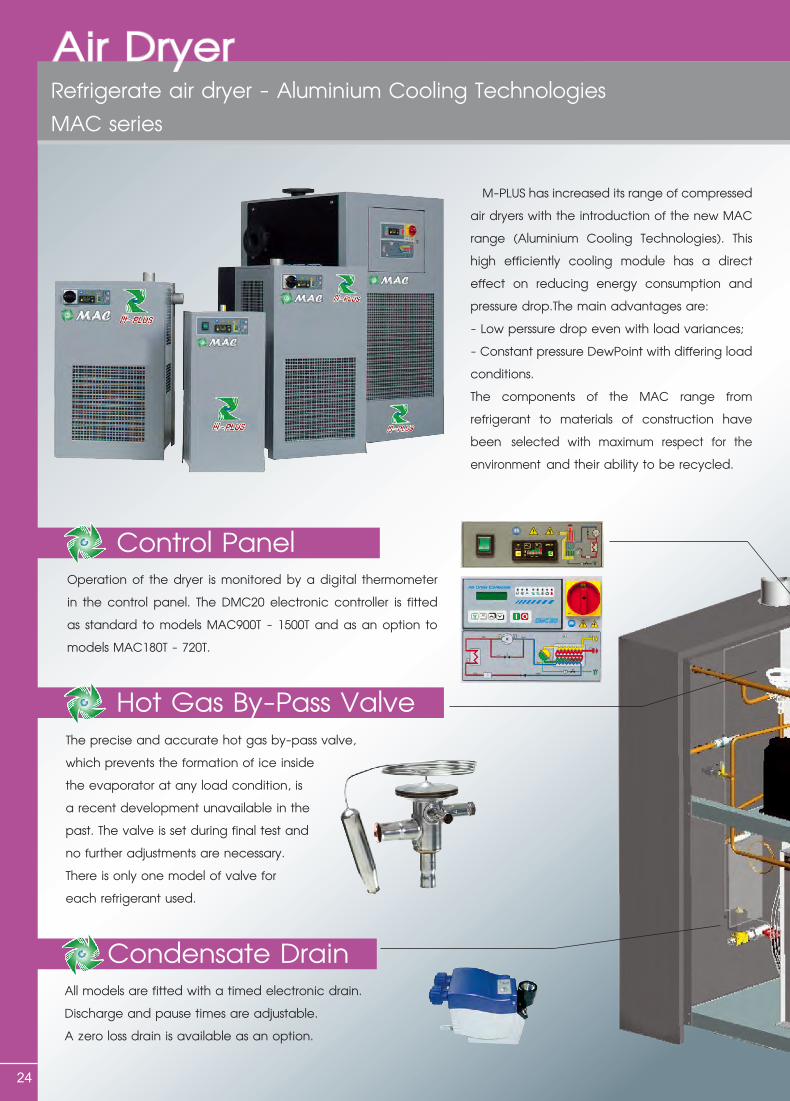
M-PLUS has increased its range of compressed air dryers with the introduction of the new MAC range (Aluminium Cooling Technologies). This high efficiently cooling module has a direct effect on reducing energy consumption and pressure drop.The main advantages are:-Lowperssuredropevenwithloadvariances;- Constant pressure DewPoint with differing load conditions.The components of the MAC range from refrigerant to materials of construction have been selected with maximum respect for the environment and their ability to be recycled.
Operation of the dryer is monitored by a digital thermometer in the control panel. The DMC20 electronic controller is fitted as standard to models MAC900T - 1500T and as an option to models MAC180T - 720T.
The precise and accurate hot gas by-pass valve, which prevents the formation of ice inside the evaporator at any load condition, is a recent development unavailable in the past. The valve is set during final test and no further adjustments are necessary. There is only one model of valve for each refrigerant used.
All models are fitted with a timed electronic drain. Discharge and pause times are adjustable. A zero loss drain is available as an option.
Refrigerate air dryer - Aluminium Cooling TechnologiesMAC series
Air Dryer
Alu-Dry Module
Condenser
25
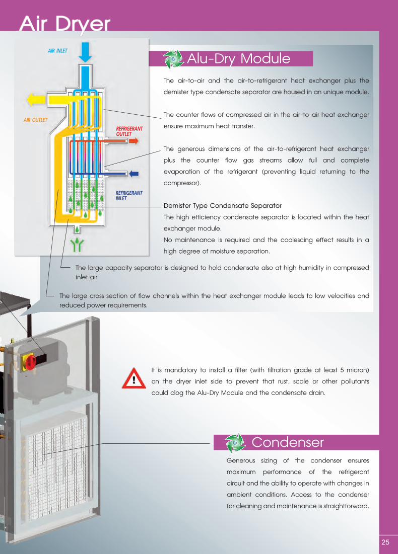
The air-to-air and the air-to-refrigerant heat exchanger plus the demister type condensate separator are housed in an unique module.
The counter flows of compressed air in the air-to-air heat exchanger ensure maximum heat transfer.
The generous dimensions of the air-to-refrigerant heat exchanger plus the counter flow gas streams allow full and complete evaporation of the refrigerant (preventing liquid returning to the compressor).
Demister Type Condensate SeparatorThe high efficiency condensate separator is located within the heat exchanger module.No maintenance is required and the coalescing effect results in a high degree of moisture separation.
The large capacity separator is designed to hold condensate also at high humidity in compressed inlet air
The large cross section of flow channels within the heat exchanger module leads to low velocities and reduced power requirements.
It is mandatory to install a filter (with filtration grade at least 5 micron) on the dryer inlet side to prevent that rust, scale or other pollutants could clog the Alu-Dry Module and the condensate drain.
Generous sizing of the condenser ensures maximum performance of the refrigerant circuit and the ability to operate with changes in ambient conditions. Access to the condenser for cleaning and maintenance is straightforward.
Air DryerAIR INLET
REFRIGERANTOUTLET
REFRIGERANTINLET
AIR OUTLET
26
Air DryerTechnical Features
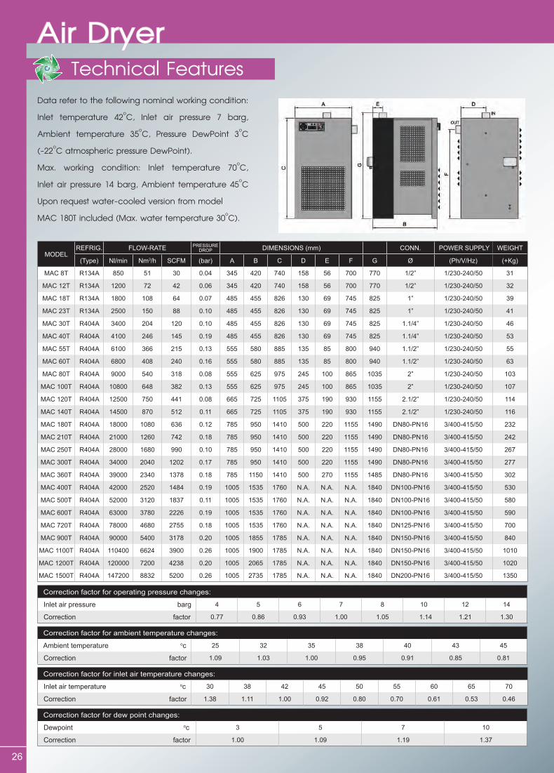
Data refer to the following nominal working condition:
Inlet temperature 42oC, Inlet air pressure 7 barg,
Ambient temperature 35oC, Pressure DewPoint 3oC
(-22oC atmospheric pressure DewPoint).
Max. working condition: Inlet temperature 70oC,
Inlet air pressure 14 barg, Ambient temperature 45oC
Upon request water-cooled version from model
MAC 180T included (Max. water temperature 30oC).
MODELREFRIG. FLOW-RATE PRESSURE
DROP DIMENSIONS (mm) CONN. POWER SUPPLY WEIGHT
(Type) Nl/min Nm3/h SCFM (bar) A B C D E F G Ø (Ph/V/Hz) (+Kg)
MAC 8T R134A 850 51 30 0.04 345 420 740 158 56 700 770 1/2” 1/230-240/50 31
MAC 12T R134A 1200 72 42 0.06 345 420 740 158 56 700 770 1/2” 1/230-240/50 32
MAC 18T R134A 1800 108 64 0.07 485 455 826 130 69 745 825 1” 1/230-240/50 39
MAC 23T R134A 2500 150 88 0.10 485 455 826 130 69 745 825 1” 1/230-240/50 41
MAC 30T R404A 3400 204 120 0.10 485 455 826 130 69 745 825 1.1/4” 1/230-240/50 46
MAC 40T R404A 4100 246 145 0.19 485 455 826 130 69 745 825 1.1/4” 1/230-240/50 53
MAC 55T R404A 6100 366 215 0.13 555 580 885 135 85 800 940 1.1/2” 1/230-240/50 55
MAC 60T R404A 6800 408 240 0.16 555 580 885 135 85 800 940 1.1/2” 1/230-240/50 63
MAC 80T R404A 9000 540 318 0.08 555 625 975 245 100 865 1035 2” 1/230-240/50 103
MAC 100T R404A 10800 648 382 0.13 555 625 975 245 100 865 1035 2” 1/230-240/50 107
MAC 120T R404A 12500 750 441 0.08 665 725 1105 375 190 930 1155 2.1/2” 1/230-240/50 114
MAC 140T R404A 14500 870 512 0.11 665 725 1105 375 190 930 1155 2.1/2” 1/230-240/50 116
MAC 180T R404A 18000 1080 636 0.12 785 950 1410 500 220 1155 1490 DN80-PN16 3/400-415/50 232
MAC 210T R404A 21000 1260 742 0.18 785 950 1410 500 220 1155 1490 DN80-PN16 3/400-415/50 242
MAC 250T R404A 28000 1680 990 0.10 785 950 1410 500 220 1155 1490 DN80-PN16 3/400-415/50 267
MAC 300T R404A 34000 2040 1202 0.17 785 950 1410 500 220 1155 1490 DN80-PN16 3/400-415/50 277
MAC 360T R404A 39000 2340 1378 0.18 785 1150 1410 500 270 1155 1485 DN80-PN16 3/400-415/50 302
MAC 400T R404A 42000 2520 1484 0.19 1005 1535 1760 N.A. N.A. N.A. 1840 DN100-PN16 3/400-415/50 530
MAC 500T R404A 52000 3120 1837 0.11 1005 1535 1760 N.A. N.A. N.A. 1840 DN100-PN16 3/400-415/50 580
MAC 600T R404A 63000 3780 2226 0.19 1005 1535 1760 N.A. N.A. N.A. 1840 DN100-PN16 3/400-415/50 590
MAC 720T R404A 78000 4680 2755 0.18 1005 1535 1760 N.A. N.A. N.A. 1840 DN125-PN16 3/400-415/50 700
MAC 900T R404A 90000 5400 3178 0.20 1005 1855 1785 N.A. N.A. N.A. 1840 DN150-PN16 3/400-415/50 840
MAC 1100T R404A 110400 6624 3900 0.26 1005 1900 1785 N.A. N.A. N.A. 1840 DN150-PN16 3/400-415/50 1010
MAC 1200T R404A 120000 7200 4238 0.20 1005 2065 1785 N.A. N.A. N.A. 1840 DN150-PN16 3/400-415/50 1020
MAC 1500T R404A 147200 8832 5200 0.26 1005 2735 1785 N.A. N.A. N.A. 1840 DN200-PN16 3/400-415/50 1350
Correction factor for operating pressure changes:
Inlet air pressure barg 4 5 6 7 8 10 12 14
Correction factor 0.77 0.86 0.93 1.00 1.05 1.14 1.21 1.30
Correction factor for ambient temperature changes:
Ambient temperature oc 25 32 35 38 40 43 45
Correction factor 1.09 1.03 1.00 0.95 0.91 0.85 0.81
Correction factor for inlet air temperature changes:
Inlet air temperature oc 30 38 42 45 50 55 60 65 70
Correction factor 1.38 1.11 1.00 0.92 0.80 0.70 0.61 0.53 0.46
Correction factor for dew point changes:
Dewpoint oc 3 5 7 10
Correction factor 1.00 1.09 1.19 1.37

27
Type ConnectionsSize H h D Chart
MF-05 1/2” 159 125 80
Chart 1
MF-07 3/4” 180 156 87
MF-10 1” 218 183 99
MF-12 1 1/4” 218 183 99
MF-15 1 1/2” 340 297 133
MF-20 2” 470 432 133
MF-30 3” 588 467 173X173Chart 2
MF-60 6” 790 619 275X275
Muffler / Silencer
Producted as a kind of unique air exhaust muffler after we researching correlative productions of Allied witan
in U.S. Material primary of glass-cotton and the others from U.S. have the same function as the imported ones
by reducing noise at heats by 30dB. By-pass safe valve turns on above 2.0 kgf/cm2 to point out replacement.
Suitable for absorbent dryer whose operation pressure is 1.0 MPa.
Technical & Dimensions
28
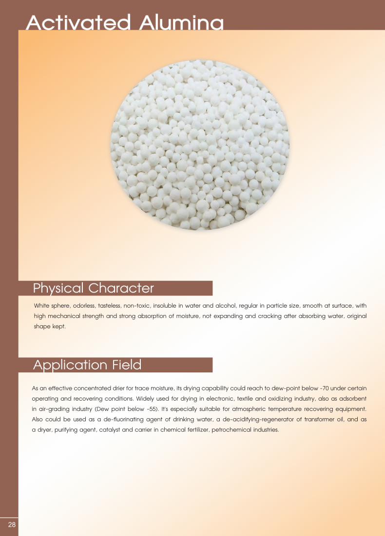
White sphere, odorless, tasteless, non-toxic, insoluble in water and alcohol, regular in particle size, smooth at surface, with high mechanical strength and strong absorption of moisture, not expanding and cracking after absorbing water, original shape kept.
As an effective concentrated drier for trace moisture, its drying capability could reach to dew-point below -70 under certain operating and recovering conditions. Widely used for drying in electronic, textile and oxidizing industry, also as adsorbent in air-grading industry (Dew point below -55). It's especially suitable for atmospheric temperature recovering equipment. Also could be used as a de-fluorinating agent of drinking water, a de-acidifying-regenerator of transformer oil, and as a dryer, purifying agent, catalyst and carrier in chemical fertilizer, petrochemical industries.
Activated Alumina
Physical Character
Application Field
29
Appropriate temperature for regeneration: 120~240oCThe lowest dew point is 70oC, and its regeneration temperature is relative low.Regeneration: in the air or inert gas, keep the temperature between 120~240oC.However, exact regenerated temperature should depend on the actual regeneration time and the saturation degree of activated alumina. In other words, the more saturation degree the alumina is, the higher the regeneration temperature will be. The less the regeneration time is, the higher the regeneration temperature. But the temperature should be within 120~240oC. But please be noted, activated alumina's usage rate and absorption ability will be decreased after regeneration. (However, molecular sieve won't)
Activated Alumina should be stored at room temperature, in which the relative humidity is not exceed 90%, and be not exposed in air, and prevented against water, acids and alkalies.
Activated Alumina
Technique Specification
Regeneration
Storage
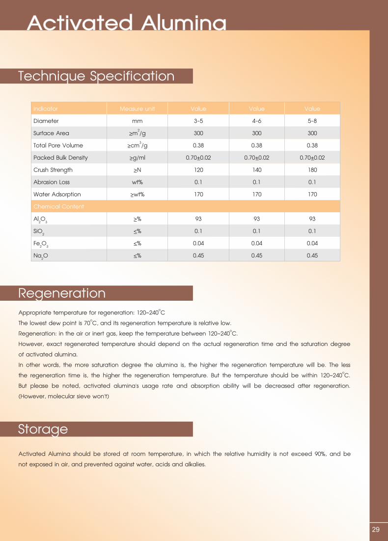
Indicator Measure unit Value Value Value
Diameter mm 3-5 4-6 5-8
Surface Area >m2/g 300 300 300
Total Pore Volume >cm3/g 0.38 0.38 0.38
Packed Bulk Density >g/ml 0.70+0.02 0.70+0.02 0.70+0.02
Crush Strength >N 120 140 180
Abrasion Loss wt% 0.1 0.1 0.1
Water Adsorption >wt% 170 170 170
Chemical Content
Al2O3 >% 93 93 93
SiO2 <% 0.1 0.1 0.1
Fe2O3 <% 0.04 0.04 0.04
Na2O <% 0.45 0.45 0.45
30
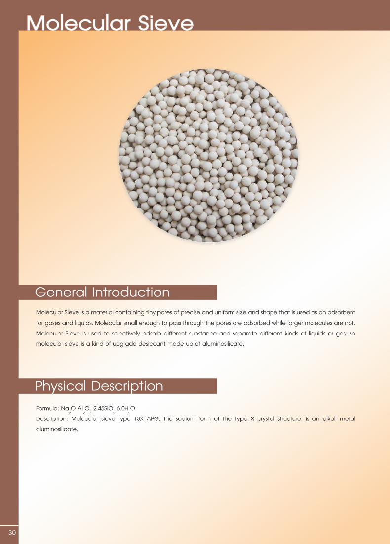
Molecular Sieve is a material containing tiny pores of precise and uniform size and shape that is used as an adsorbent for gases and liquids. Molecular small enough to pass through the pores are adsorbed while larger molecules are not. MolecularSieveisusedtoselectivelyadsorbdifferentsubstanceandseparatedifferentkindsofliquidsorgas;so molecular sieve is a kind of upgrade desiccant made up of aluminosilicate.
Formula: Na2O AI
2O
3 2.45SiO
2 6.0H
2O
Description: Molecular sieve type 13X APG, the sodium form of the Type X crystal structure, is an alkali metal aluminosilicate.
Molecular Sieve
General Introduction
Physical Description

31
Usedcommerciallyforgeneralgasdrying;Air plant feed purification (simultaneous removal of H
2O and CO
2);
Liquid hydrocarbon and natural gas sweetening (H2Sandmercaptanremoval);
13X APG molecular sieve can adsorb both the moisture and polymerization by-products such as acetaldehyde and ethylene glycol.
It should be stored at room temperature, in which the relative humidity is not exceed 90%, and be not exposed in air, and prevented against water, acids and alkalies.
Molecular Sieve
Application Field
Technique Specification
Storage
Indicator Measure unit Value
Diameter mm 1.6-2.5 3-5
Static Water Adsorption >mg/g 270 270
CO2 Adsorption >mg/g 180 180
Packed Bulk Density g/ml 0.67+0.02 0.66+0.02
Crush Strength >N 30 80
Wear Rate <wt% 0.10 0.10
Package Moisture <wt% 1.0 1.0
DistributorM-Plus Filtration Co., Ltd.91/22 Moo 9, Ngamwongwan Rd.,T.Bangkrasor, A.Muang, Nonthaburi, 11000 Thailand.Tel. (66) 0 2588-5883, 0 2953 5783-4Fax. (66) 0 2591 9388E-mail: [email protected]


![Understanding of ISO9000 Standards[1]](https://img.pdfslide.us/doc/110x75/577cd7871a28ab9e789f3545/understanding-of-iso9000-standards1.jpg)