Embed Size (px)
Citation preview

MADE IN THE USA12.2015.a
THE BEST OF THE BEST

1
Compact Diaphragm Valves have a face to face that is interchangeable with most solid wedge double disc and resilient wedge gate valves as well as most short pattern plug and ball valves, using ANSI B16.10 as a standard. These valves are the best for O.E.M.’s and other usage on new projects. Straight thru valves are referred to as Tru-Flow and Enhanced Weir valves are referred to as Tru-Trol.
Standard Diaphragm Valves have a face to face that is interchangeable with most other brands of diaphragm valves, using MSS SP-88 as a standard. These valves are used on replacement projects where existing piping integrity must be maintained. Straight thru valves are referred to as Maxi-Flow and Enhanced Weir valves are referred to as Maxi-Trol.
Tru-Tech Valves are designed in CAD, and incorporated into each and every valve is the latest available state of the art engineering technology. This ensures our customers that valves installed in their system will provide the maximum degree of performance and the longest possible service life.
Tru-Tech valve parts are manufactured on the latest state-of-the-art machining and turning centers. Parts manufactured today are 100% interchangeable with parts manufactured many years ago and far into the future.
Tru-Tech “Diaphragm Valves” are quality checked, assembled, and tested by skilled technicians who take pride in their ability to integrate old world craftsmanship into modern high-tech products.
Industrial/Municipal Water & Wastewater TreatmentTru-Tech ENHANCED WEIR Diaphragm Valves provide an inexpensive means of fluid control for reverse osmosis, deionization, filtration, chemical feeders, and demineralizers. STRAIGHT THRU valves are used in slurry and/or abrasive applications. Installations include manual, pneumatically, and electrically actuated valves.
ChemicalTru-Tech ENHANCED WEIR Diaphragm Valves are available in a wide variety of body linings and diaphragm materials. This versatility makes them suitable for handling a wide variety of acids and other corrosive fluids. Installations include both manual and pneumatically actuated valves.
MiningTru-Tech STRAIGHT THRU rubber lined Diaphragm Valves are normally used for handling abrasive and/or slurry applications. ENHANCED WEIR valves are normally utilized in chemical and process feed lines.
Pulp & PaperTru-Tech ENHANCED WEIR Diaphragm Valves are normally used in clean fluid servicessuch as bleaching and coating processes, and chemical and water treatment. Tru-Tech STRAIGHT THRU Diaphragm Valves are normally used for slurry services such as lime, mud, and titanium dioxide lines. Installations include both manual and pneumatically actuated valves.
PowerTru-Tech ENHANCED WEIR Diaphragm Valves are commonly utilized in chemical and demineralizer systems. STRAIGHT THRU rubber lined valves are used for flue gas desulfurization. Installations include both manual and pneumatically actuated valves.
TYPICAL APPLICATIONSPRODUCTS “The Best of the Best”
2 3

TRU-TECH DIAPHRAGM VALVE EXTRA FEATURES AND ADVANTAGES
DIAPHRAGM VALVE STANDARD FEATURES AND ADVANTAGES
Diaphragm valves have unique design features not offered in other types of valves. These unique advantages include in-line maintenance, positive bubble-tight closure, bonnet isolation, streamlined flow passage without recesses or pockets, and no packing glands.
A fully functioning rubber diaphragm seals leak-tight against the valve body, completely isolating all the mechanical working parts of the valve’s operating mechanism from the fluid. This total separation between the media passing through the valve and the bonnet also eliminates troublesome stem seal and packing gland problems as well as providing fugitive emission protection.
A wide range of body linings and diaphragm materials provide a cost effective solution to readily handling corrosive and abrasive liquids as well as liquids with suspended solids.
Another advantage of the diaphragm valve is that it does not seize up like eccentric plug valves and is an excellent solution for replacing problem valves.
SELECTING THE PROPER DIAPHRAGM VALVE FOR YOR APPLICATION
1. SERVICE CONDITIONS? What is the fluid being handled? It could be hydrochloric acid, tap water, or something in be-tween. Note also that it could be a combination of two or more things.
2. CONCENTRATION OF FLOWING FLUID? The concentration af-fects the proper choice of body lining and diaphragm material.
3. SYSTEM OPERATING TEMPERATURE? Many chemicals are more aggressive at elevated temperatures. Plus, body linings and diaphragm materials are pressure/temperature rated.
4. SYSTEM OPERATING PRESSURE? Most diaphragm valves are pressure limited. Consult manufacturers recomendations for system compatibility.
WHY DO TRU-TECH VALVES LAST LONGER?
The Tru-Tech valve reduces diaphragm flex by contracting the vertical height of the flow area and expanding the width. The resultant body shape provides the laminar flow characteristics of a venturi, and allows less turbulence to the flow media. In addition, the reduced flex results in a longer diaphragm life.
In addition to many features found in all diaphragm valves, Tru-Tech’s valves have several added advantages of their own.
Our diaphragm valves are available in two face to face configurations, MSS and ANSI. Tru-Tech Valve meets MSS SP-88 standards, permitting direct replacement of most other brands of diaphragm valves, allowing our valves to be used where customers are upgrading existing systems utilizing diaphragm valves. Tru-Tech also meets ANSI B16.10 standards, permitting direct replacement of most brands of gate, plug, and ball valves.
Tru-Tech STRAIGHT THRU valves are available with a TFE faced diaphragm which expands the range of applications that can be handled. This feature is not offered by any other brand of diaphragm valves.
Tru-Tech manual valves are furnished standard with travel stops. Pneumatically operated valves are available with optional travel stops, but are furnished as standard where our engineering department feels the operator may be oversized. Travel stops help to prevent the number one cause of failure and reduced life in diaphragm valves; mainly, over-closure by zealous operators.
Other Features and Advantages Include:• Stud pull out is the number two cause of failure in other brands of diaphragm valves. All Tru-Tech diaphragms
are double studded, providing an extra margin of performance, especially in vacuum service.• Tru-Tech’s manual valve operators are supplied with heavy duty acme threads capable of providing heavy
thrusts and thousands of operations. Some other brands use limited duty v-threads not recommended for a great number of operations.
• All Tru-Tech valves can be rodded out where clogging occurs. • Tru-Tech Valve manufactures its own pneumatic actuators, providing our customers with one source
responsibility for the total package. • All Tru-Tech valves are furnished with position indicators showing whether the valve is open, closed, or
throttling. • Unlined valve bodies and all operators are powder coated, inside and out, with a TGIC polyester powder
formulated for maximum chemical and weather resistance. Plastic lined valves are furnished with bodies completely encapsulated with the latest state-of-the-art fusion-bonded liner. Each and every valve body lining is spark tested to ensure lining thickness and integrity.
4 5

NOTES:ANSI face to face dimensions does not apply to screwed (NPT) or SW ends. The use of gaskets for plastic lined valves is strongly recommended.ANSI face to face valves interchange with most gate, plug, and ball valves. MSS face to face valves interchange with most other brands of diaphram valves.Valves may have a combination of drilled holes and threaded holes on flanges, contact Tru-Tech Valve for additional information.
Flan
ged
Ends
MAXI-TROL AND TRU-TROL VALVE GENERAL DIMENSIONS
Valve Size A B
CMAXI-TROL (MSS Length)
CTRU-TROL
(ANSI Length)
Weight (lbs) D E
Body Pres-sure
Rating (PSI)Plastic Lined
Rubber Lined
Weight (lbs)
½ 4.00 4.69 5.75* 5.75* 7.00 5.00 6.50 3.50 3.50 200¾ 4.00 4.69 5.75 5.75 7.00 5.00 6.50 3.50 3.50 2001 4.00 5.75 5.75 5.75 7.00 5.00 6.50 4.25 3.50 200
1 ¼ 5.50 6.13 5.75* 5.75* 14.00 5.00 12.00 5.00 5.00 1751 ½ 5.50 7.00 7.88* 7.88* 12.00 7.00 14.00 5.00 5.00 175
2 7.00 8.00 7.88 7.88 25.00 7.00 21.00 6.00 5.00 1752 ½ 7.25 9.00 10.25* 10.25* 55.00 8.00 35.00 7.00 7.00 150
3 7.25 9.50 10.25 10.25 55.00 8.00 35.00 7.50 7.00 1504 8.38 10.50 12.88 12.75 80.00 9.00 51.50 9.00 9.00 1506 11.00 14.50 16.38 16.25 104.00 10.50 80.00 11.00 12.00 1258 17.88 17.88 20.88 20.88 231.00 11.50 165.00 13.75 14.00 100
10 17.88 17.88 25.38 25.75 265.00 NA NA 16.00 14.00 65
B MAX.
D
C
AB
E DIA.
Flanged Body
Scre
wed
End
s
SCREWED END - VALVE GENERAL DIMENSIONS
Valve Size A B C Weight (lbs) D E Body Pressure
Rating (PSI)
½ 4.00 4.69 7.25 5.00 1.88 3.50 200¾ 4.00 4.69 7.25 5.00 1.88 3.50 2001 4.00 4.69 7.25 5.00 1.88 3.50 200
1 ½ 5.50 6.13 8.50 13.00 3.25 7.00 1752 5.50 6.13 8.50 13.00 3.25 7.00 175
2 ½ 8.38 10.50 10.50 35.00 4.50 9.00 1503 8.38 10.50 10.50 35.00 4.50 9.00 150
Flan
ged
Ends
MAXI-FLOW AND TRU-FLOW VALVE GENERAL DIMENSIONS
Valve Size A B
CMAXI-FLOW (MSS Length) C
TRU-FLOW(ANSI Length)
Weight (lbs) D E Body Pressure
Rating (PSI)Plastic Lined
Rubber Lined
Weight (lbs)
½ 4.00 4.69 5.75* 5.75* 11.00 5.00 10.00 3.50 3.50 200¾ 4.00 4.69 5.75 5.75 11.00 5.00 10.00 3.50 3.50 2001 4.00 4.69 5.75 5.75 11.00 5.00 10.00 3.50 3.50 200
1 ¼ 4.00 4.69 5.75* 5.75* 11.00 5.00 10.00 3.50 3.50 2001 ½ 7.25 9.00 7.88* 7.88* 27.00 7.00 25.00 6.00 7.00 175
2 7.25 9.50 7.88 7.88 27.00 7.00 25.00 6.00 7.00 1752 ½ 8.38 10.50 10.25* 10.25* 35.00 8.00 45.00 7.00 9.00 150
3 8.38 10.38 10.25 10.25 52.00 8.00 45.00 7.50 9.00 1504 11.25 14.00 12.88 12.75 80.00 9.00 70.00 9.00 12.00 1506 17.88 22.00 16.38 16.25 160.00 10.50 125.00 11.13 14.13 125
D
D
C C
B MAX.AB
B MAX.
E DIA.E DIA.
Flanged Body Screwed End Body andSocket & Butt Weld Body
STRAIGHT THRU DIAPHRAGM VALVESENHANCED WEIR DIAPHRAGM VALVES
6 7
Tolerances: Unlined - 1/16”, Lined - 1/8” All dimensions are in inches NA - Not Available*Valve length does not meet either MSS or ANSI specifications.
Tolerances: Unlined - 1/16”, Lined - 1/8” All dimensions are in inches NA - Not Available*Valve length does not meet either MSS or ANSI specifications.See NOTES on page 6.

DIAPHRAGM: Molded of nylon reinforced oil-resistant elastomer to provide longer
life and high operating pressures.
SHAFT(Stem):Precision machined from stainless
steel for corrosion and wear resistance. Unique collar
controls opening stroke and extends cycle life under load.
SHAFT SEAL: Furnished standard with two (2 each)
O-rings for longer trouble free performance.
DIAPHRAGM PLATES: Manufactured from heavy section cast iron or steel plate to withstand higher air pressure.
DIAPHRAGM CASE: Rugged high strength cast iron with bosses and pads to facilitate the mounting of accessories.
BONNET: Designed of high strength cast iron with generous area flat top for precision/super high strength coupling between actuator and valve.
SHAFT BEARING: Precision machined from non-metallic self-lubricating material.
Accessories are easily field mounted.
Position Indicator is furnished as standard.
“SO” SPRING TO OPEN(ON - OFF CONTROL)
This actuator/accessory package is designed to normally position the valve open. The valve will close when compressed air is admitted into the upper actuator chamber, and the actuator spring will open the valve when the air is exhausted.
“AA” AIR-AIR, DOUBLE ACTING(ON - OFF CONTROL)
This actuator/accessory package is designed to open the valve when compressed air is admitted into the lower chamber, and closes the valve when compressed air is admitted into the upper chamber.
“AA” AIR-AIR, DOUBLE ACTING(AUTOMATIC THROTTLING)
This actuator/accessory package is provided with a positioner to accurately throttle the valve for pressure, liquid level, flow, temperature, and other control requirements. A transducer is generally supplied to provide valve modulation proportional to an electric signal (most often 4-20 ma).
“SC” SPRING TO CLOSE(ON - OFF CONTROL or AUTOMATIC THROTTLING-not shown)
This actuator/accessory package is designed to normally position the valve closed. The valve will open when compressed air is admitted into the lower actuator chamber, and the actuator spring will close the valve when the air is exhausted.
AIRSUPPLY
3-WAYSOLENOID
REGULATOR
EXH.
SOL
AIRSUPPLY
4-WAYSOLENOID
REGULATOR EXH.
SOL
REGULATOR
AIRSUPPLY
EXH.
SOLREGULATOR
AIRSUPPLY
3-WAYSOLENOID
FILTER/REG.W/GAUGE
TRANSDUCER
OPTIONAL
PNEUMATIC ACTUATOR OPERATIONPNEUMATIC ACTUATOR FEATURES
8 9

Dimensions are approximate only.Valves may have a combination of drilled and threaded holes on flanges.Contact Tru-Tech Valve for additional information.
Dimensions are approximate only.Valves may have a combination of drilled and threaded holes on flanges.Contact Tru-Tech Valve for additional information.
Pneumatic Actuator Dimensions and Technical Data
Valve Size C D E#10 Actuator #20 Actuator #30 Actuator Valve Stroke
A1 A2 B A1 A2 B A1 A2 B TF TT½ 5.0 2.6 2.8 9.3 19.1 6.3 9.4 19.2 7.8 11.1 20.9 9.5 0.33 0.33¾ 5.0 2.6 2.8 9.3 19.1 6.3 9.4 19.2 7.8 11.1 20.9 9.5 0.33 0.331 5.0 2.6 2.8 9.3 19.1 6.3 10.1 19.9 7.8 11.8 21.7 9.5 0.47 0.33
1 ¼ 7.0 2.6 2.8 10.1 19.8 6.3 10.2 24.6 7.8 11.4 26.4 9.5 0.75 0.471 ½ 7.0 2.6 2.8 10.1 19.8 6.3 10.2 24.6 7.8 11.4 26.4 9.5 0.75 0.47
2 7.0 2.6 2.8 10.1 19.8 6.3 10.2 24.6 7.8 11.4 26.4 9.5 0.75 0.472 ½ 8.0 3.3 3.5 NA NA NA 10.6 25.6 7.8 12.4 27.3 9.5 1.19 0.75
3 8.0 3.3 3.5 NA NA NA 10.6 25.6 7.8 12.4 27.3 9.5 1.19 0.754 9.0 3.3 3.5 NA NA NA NA NA NA 13.9 28.9 9.5 1.78 1.19
Actuator Stroke (in.) 1.75 2.25 2.75Effective Area (sq. in.) 14 19 34Maximum Air Pressure
(PSI) 100
ACTUATOR SIZES 10 - 20 - 35
B DIA.
B DIA.
B DIA.
C CC
A1
A2
A1
DDIA.
EMAX.
“AA”AIR TO OPENAIR TO CLOSE
“SO”SPRING TO OPEN
AIR TO CLOSE
“SC”SPRING TO CLOSE
AIR TO OPEN
Pneumatic Actuator Dimensions and Technical Data
Valve Size C D E
#60 Actuator #90 Actuator #140 Actuator #280 Actuator Valve Stroke
A1 A2 B A1 A2 B A1 A2 B A1 A2 B TF TT1 ½ 7.0 2.6 2.8 12.1 27.1 12.3 NA NA NA NA NA NA NA NA NA 0.75 0.47
2 7.0 2.6 2.8 12.1 27.1 12.3 12.1 41.5 15.0 NA NA NA NA NA NA 0.75 0.472 ½ 8.0 3.3 3.5 13.1 28.1 12.3 13.1 42.5 15.0 14.2 43.8 18.0 NA NA NA 1.19 0.75
3 8.0 3.3 3.5 13.1 28.1 12.3 13.1 42.5 15.0 14.2 43.8 18.0 NA NA NA 1.19 0.754 9.0 3.3 3.5 14.7 29.7 12.3 14.8 44.0 15.0 15.8 45.8 18.0 27.2 57.3 18.0 1.78 1.195 10.5 4.8 5.0 18.2 33.2 12.3 18.3 47.6 15.0 19.3 48.9 18.0 31.2 60.8 18.0 2.63 1.786 10.5 4.8 5.0 18.2 33.2 12.3 18.3 47.6 15.0 19.3 48.9 18.0 31.2 60.8 18.0 2.63 1.788 11.5 4.8 5.0 18.2 33.2 12.3 18.3 47.6 15.0 19.3 48.9 18.0 31.2 60.8 18.0 - 2.63Actuator Stroke (in.) 3.13 4.10 5.00 5.00
Effective Area (sq. in.) 59 85 141 281Maximum Air Pressure
(PSI) 100
ACTUATOR SIZES 60 - 90 - 140 - 280
B DIA.
B DIA.
B DIA.
C CC
A1
A2
A1
DDIA.
EMAX.
“AA”AIR TO OPENAIR TO CLOSE
“SO”SPRING TO OPEN
AIR TO CLOSE
“SC”SPRING TO CLOSE
AIR TO OPEN
PNEUMATIC ACTUATOR DIMENSIONSAND TECHNICAL DATA
PNEUMATIC ACTUATOR DIMENSIONSAND TECHNICAL DATA
10 11
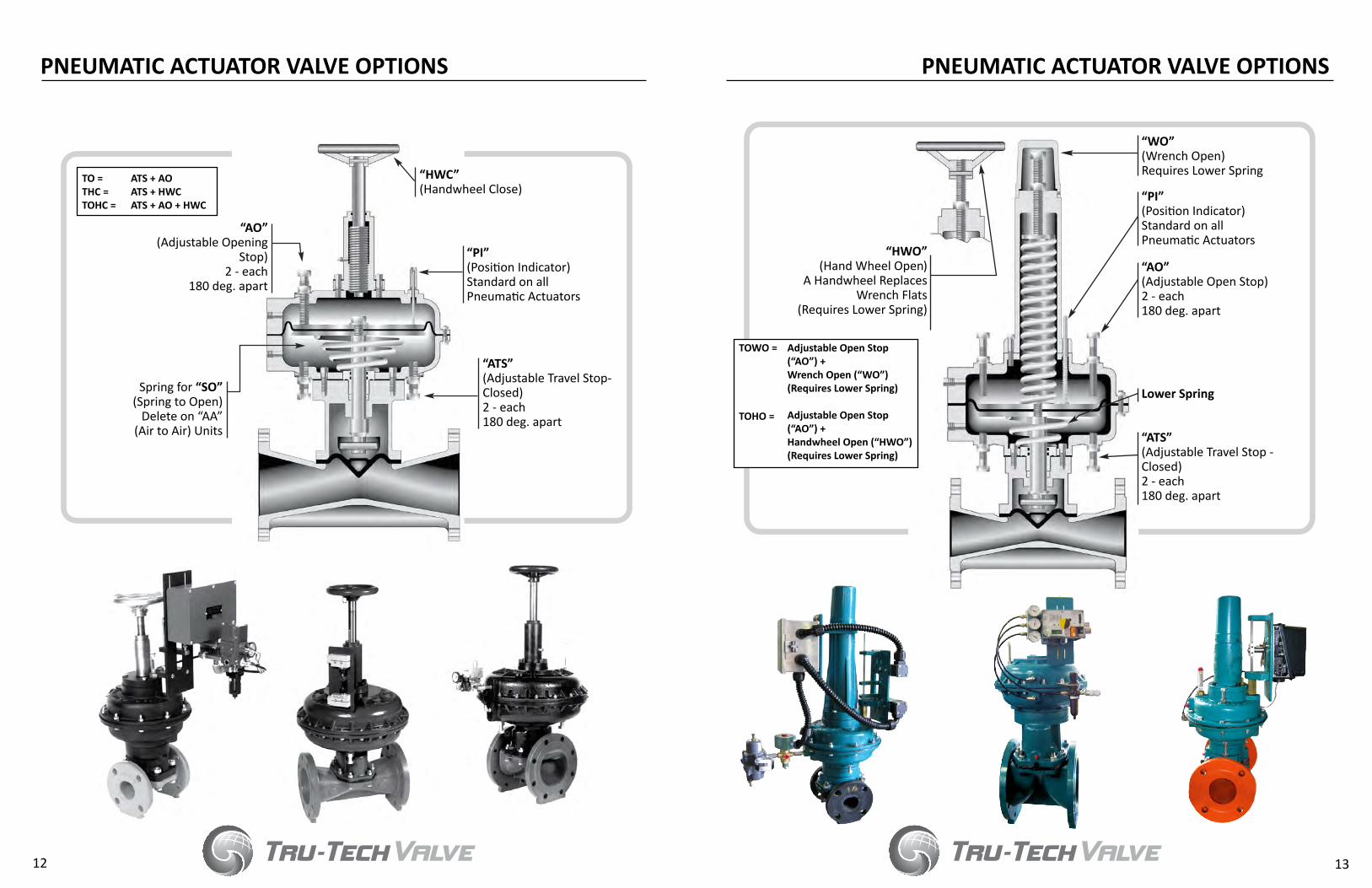
ATS + AOATS + HWCATS + AO + HWC
TO =THC =TOHC =
“AO”(Adjustable Opening
Stop)2 - each
180 deg. apart
Spring for “SO”(Spring to Open)
Delete on “AA”(Air to Air) Units
“HWC”(Handwheel Close)
“PI”(Position Indicator)Standard on all Pneumatic Actuators
“ATS”(Adjustable Travel Stop-Closed)2 - each180 deg. apart
“HWO”(Hand Wheel Open)
A Handwheel Replaces Wrench Flats
(Requires Lower Spring)
Adjustable Open Stop (“AO”) +Wrench Open (“WO”) (Requires Lower Spring)
Adjustable Open Stop (“AO”) +Handwheel Open (“HWO”)(Requires Lower Spring)
TOWO =
TOHO =
“WO”(Wrench Open)Requires Lower Spring
“PI”(Position Indicator)Standard on all Pneumatic Actuators
“AO”(Adjustable Open Stop)2 - each180 deg. apart
Lower Spring
“ATS”(Adjustable Travel Stop - Closed)2 - each180 deg. apart
PNEUMATIC ACTUATOR VALVE OPTIONSPNEUMATIC ACTUATOR VALVE OPTIONS
12 13

EXAMPLE:Given a 2” WEIR type valve, elastomer diaphragm with a maximum fluid pressure of 100 PSI, a minimumavailable air pressure of 50 PSI, and an operator action SC, select #35 Pneumatic Operator. NOTE: Unit will function at 40 PSI.
TO SELECT CORRECT OPERATOR:
1. Select valve and topworks size (see Chart B)2. Determine diaphragm type3. Determine maximum fluid line pressure (PSIG)4. Determine minimum air supply pressure (PSI)5. Select operator action (AA, SO, SC) AA - Air to Open, Air to Close SO - Spring to Open, Air to Clost SC - Spring to Close, Air to Open6. From Chart A, determine the smallest suitable
operator
NUMBER 35 OPERATOR
ELASTOMER DIAPHRAGM
LINE PRESSURE - PSIGAI
R PR
ESSU
RE -
PSI
120
100
80
60
40
20
00 20 40 60 80 100 120 140 160 180
CHART A
SC ACTION
CHART B
TTV DIAPHRAGM VALVE AND PNEUMATIC OPERATOR SIZING
TTV DIAPHRAGM VALVE AND PNEUMATIC OPERATOR SIZING
14 15
NUMBER 10 OPERATORS
NUMBER 20 OPERATORS
AA & SO ACTION
SC ACTION
AA & SO ACTION
SC ACTION
AA & SO ACTION
SC ACTION
AA & SO ACTION
SC ACTION
ELASTOMER DIAPHRAGM
LINE PRESSURE - PSIG
AIR
PRES
SURE
- PS
I
120
100
80
60
40
20
00 20 40 60 80 100 120 140 160 180
TEFLON DIAPHRAGM
LINE PRESSURE - PSIG
AIR
PRES
SURE
- PS
I
120
100
80
60
40
20
00 20 40 60 80 100 120 140 160 180
ELASTOMER DIAPHRAGM
LINE PRESSURE - PSIG
AIR
PRES
SURE
- PS
I
120
100
80
60
40
20
00 20 40 60 80 100 120 140 160 180
TEFLON DIAPHRAGM
LINE PRESSURE - PSIG
AIR
PRES
SURE
- PS
I
120
100
80
60
40
20
00 20 40 60 80 100 120 140 160 180
E DC
B
A C
B
A
C
B
A
B
A
B
A
ELASTOMER DIAPHRAGM
LINE PRESSURE - PSIG
AIR
PRES
SURE
- PS
I
120
100
80
60
40
20
00 20 40 60 80 100 120 140 160 180
TEFLON DIAPHRAGM
LINE PRESSURE - PSIG
AIR
PRES
SURE
- PS
I
120
100
80
60
40
20
00 20 40 60 80 100 120 140 160 180
ELASTOMER DIAPHRAGM
LINE PRESSURE - PSIGAI
R PR
ESSU
RE -
PSI
120
100
80
60
40
20
00 20 40 60 80 100 120 140 160 180
TEFLON DIAPHRAGM
LINE PRESSURE - PSIG
AIR
PRES
SURE
- PS
I
120
100
80
60
40
20
0 0 20 40 60 80 100 120 140 160 180
C
B
A
B
A
B
A
B
A
D C
WEIR TYPE ½ ¾ 1 1½ 2 2½ 3 4 6 8 10TOP WORKS SIZE A A A B B C C D E F F
STRAIGHT THRU TYPE ½ ¾ 1 1½ 2 2½ 3 4 6 8 10TOP WORKS SIZE A A A C C D D E F - -

TTV DIAPHRAGM VALVE AND PNEUMATIC OPERATOR SIZING
TTV DIAPHRAGM VALVE AND PNEUMATIC OPERATOR SIZING
16 17
NUMBER 90 OPERATORS
NUMBER 140 OPERATORS
NUMBER 35 OPERATORS
NUMBER 60 OPERATORS
AA & SO ACTION
SC ACTION
AA & SO ACTION
SC ACTION
AA & SO ACTION
SC ACTION
AA & SO ACTION
SC ACTION
LINE PRESSURE - PSIG
AIR
PRES
SURE
- PS
I
120
100
80
60
40
20
00 20 40 60 80 100 120 140 160 180
TEFLON DIAPHRAGM
LINE PRESSURE - PSIG
AIR
PRES
SURE
- PS
I
120
100
80
60
40
20
00 20 40 60 80 100 120 140 160 180
ELASTOMER DIAPHRAGM
LINE PRESSURE - PSIG
AIR
PRES
SURE
- PS
I
120
100
80
60
40
20
00 20 40 60 80 100 120 140 160 180
TEFLON DIAPHRAGM
LINE PRESSURE - PSIG
AIR
PRES
SURE
- PS
I
120
100
80
60
40
20
00 20 40 60 80 100 120 140 160 180
D
C
E
D
C
A
D
C
ELASTOMER DIAPHRAGM
LINE PRESSURE - PSIG
AIR
PRES
SURE
- PS
I
120
100
80
60
40
20
00 20 40 60 80 100 120 140 160 180
TEFLON DIAPHRAGM
LINE PRESSURE - PSIG
AIR
PRES
SURE
- PS
I
120
100
80
60
40
20
00 20 40 60 80 100 120 140 160 180
ELASTOMER DIAPHRAGM
LINE PRESSURE - PSIGAI
R PR
ESSU
RE -
PSI
120
100
80
60
40
20
00 20 40 60 80 100 120 140 160 180
TEFLON DIAPHRAGM
LINE PRESSURE - PSIG
AIR
PRES
SURE
- PS
I
120
100
80
60
40
20
0 0 20 40 60 80 100 120 140 160 180
F
E
C
F
D
C
F E
D
F
AA & SO ACTION
SC ACTION
AA & SO ACTION
SC ACTION
AA & SO ACTION
SC ACTION
AA & SO ACTION
SC ACTION
LINE PRESSURE - PSIG
AIR
PRES
SURE
- PS
I
120
100
80
60
40
20
00 20 40 60 80 100 120 140 160 180
TEFLON DIAPHRAGM
LINE PRESSURE - PSIG
AIR
PRES
SURE
- PS
I
120
100
80
60
40
20
00 20 40 60 80 100 120 140 160 180
ELASTOMER DIAPHRAGM
LINE PRESSURE - PSIG
AIR
PRES
SURE
- PS
I
120
100
80
60
40
20
00 20 40 60 80 100 120 140 160 180
TEFLON DIAPHRAGM
LINE PRESSURE - PSIG
AIR
PRES
SURE
- PS
I
120
100
80
60
40
20
00 20 40 60 80 100 120 140 160 180
E D
B
A
C
B
A
F E
C
B
A
ELASTOMER DIAPHRAGM
LINE PRESSURE - PSIG
AIR
PRES
SURE
- PS
I
120
100
80
60
40
20
00 20 40 60 80 100 120 140 160 180
TEFLON DIAPHRAGM
LINE PRESSURE - PSIG
AIR
PRES
SURE
- PS
I
120
100
80
60
40
20
00 20 40 60 80 100 120 140 160 180
ELASTOMER DIAPHRAGM
LINE PRESSURE - PSIG
AIR
PRES
SURE
- PS
I
120
100
80
60
40
20
00 20 40 60 80 100 120 140 160 180
TEFLON DIAPHRAGM
LINE PRESSURE - PSIG
AIR
PRES
SURE
- PS
I
120
100
80
60
40
20
0 0 20 40 60 80 100 120 140 160 180
BA
B
A
E
A
D
C
E D E D
C
BC
D
A
B
C
D
E
A
BC
D
F E
C
D
F E D
C
F E
F EF
F E
C
E
D
C
D

The effects of temperature/pressure on diaphragms and on linings in valve bodies should be considered in the selection process. The tensile properties of all materials decrease as the temperature increases. This reduction in strength can be compensated for by reducing the allowable operating pressure as fluid temperature increases.
The chemical activity of the fluid also increases as temperatures rise. This may be a consideration for choosing materials that are more corrosion-resistant.
Tru-Tech Valve WARRANTY
This Tru-Tech Valve product is made of the finest available suitable materials. Every precaution has been taken to assure premium workmanship, consistent with established quality control. Valves or parts which are proved faulty due to defective materials or poor workmanship will be replaced free of charge; F.O.B. our plant upon presentation of such proof. This warranty shall not cover the cost of installation and is valid for a period of one (1) year from date of shipment. Specifications are subject to change; certified drawings are available upon request.
FLOW VS. VELOCITY
When selecting diaphragm valves, fluid velocity is a very important design consideration. Velocity through the valve should be limited to 15-20 ft/sec for clean fluids, and 8-12 ft/sec for slurries.
WEIR - DIAPHRAGM VALVE Cv RATINGS (FLANGED ENDS) Cv FIGURES @ 100% OPEN)
Tru-Tech Diaphragm Valves, in both WEIR and STRAIGHT THRU configurations, have approximate linear values. Therefore, at 10% open, the Cv equals 10% of the full open Cv. At 25% open, the Cv equals 25% of the full open Cv and so on.
STRAIGHT THRU - DIAPHRAGM VALVE Cv RATINGS (FLANGED ENDS) Cv FIGURES @ 100% OPEN)
VALVE SIZE ¾, 1 1½ 2 2½ 3 4 6 8 10
UNLINED 50 100 100 205 205 360 625 1640 1640 PLASTIC LINED 45 94 94 200 200 350 615 1600 1600 RUBBER LINED 37 73 73 167 167 299 580 1390 1390 UNLINED 42 96 96 195 195 318 570 1250 NA PLASITC LINED 38 90 90 190 190 310 560 1220 NA RUBBER LINED 32 70 70 159 159 265 525 1060 NA
VALVE SIZE ¾, 1 1½ 2 2½ 3 4 6 8 10
UNLINED 50 275 275 425 425 740 1775 NA NA PLASTIC LINED 45 267 267 415 415 722 1735 NA NA RUBBER LINED 37 224 224 354 354 618 1511 NA NA UNLINED 42 267 267 410 410 718 1690 NA NA PLASITC LINED 38 260 260 400 400 700 1650 NA NA RUBBER LINED 32 217 217 340 340 596 1436 NA NA
MSS
MAX
I-FLO
W(L
ON
G B
ODY
)
MSS
MAX
I-TRO
L(L
ON
G B
ODY
)
COM
PACT
TRU
-TRO
L(A
NSI
)
COM
PACT
TRU
-FLO
W(A
NSI
)
GENERAL FLOW CURVE PRESSURE VS. TEMPERATURE
PERCENT OF MAXIMUM Cv TEMPERATURE (F0)
PERC
ENT
OPE
N
LIN
E PR
ESSU
RE (P
SI)
FLOW VS. VELOCITY
FLOW IN U.S. GPM (GALLONS PER MINUTE)
VELO
CITY
FPS
(FEE
T PE
R SE
CON
D)
100
90
80
70
60
50
40
30
20
10
0
VALVE Cv RATINGSENGINEERING DATA
18 19
TRU-TECH STRAIGHTTHRU TYPE VALVE
TRU-TECHENHANCEDWEIR TYPEVALVE
SAUNDERS TYPE STRAIGHT THRUVALVE
SAUNDERS TYPE WEIR VALVE
10 20 30 40 50 60 70 80 90 100
60 80 100 120 140 160 180 200 220 240 260 280 300
220
200
180
160
140
120
100
80
60
40
20
½”, ¾”, 1” VALVES1¼”, 1½”, 2” VALVES2½”, 3”, 4” VALVES5”, 6” VALVES8” VALVES
10”, 12” VALVES
20
10
864
3
2
1
.8
.62 3 4 5 7 9 20 30 40 50 70 90 200 300 500 700900 2M 3M 4M 5M 7M8M
6 8 10 60 80 100 400 600 800 1000 6M 8M 10M
9
7
5
.9
.7
.5
½” ¾” 1¼”1” 1½” 2” 2½” 3” 4” 6” 8” 10” 12”

Valve size is usually determined by the system pipe size. However, with the low pressure drop of the Tru-Tech valves it may be advantageous to design the system with a smaller pipe. It may also be desirable to calculate valve sizing in order to assure adequate and accurate throttling or flow control.
Liquid Flow: In order to simplify and standardize flow computations, valves are given a Cv rating (Fluid Controls Institute-Standard FC1 62-1) or flow coefficient. The Cv equals the flow through the valve (GPM water at 60°F) at a 1 PSI pressure drop. Flows at any other set of conditions can readily be determined from the following equations.
Q = Actual flow - gallons/min. P₁ = Pressure (PSI) immediately upstream of the valveCv = Valve flow coefficient P2 = Pressure (PSI) immediately downstream of the valve G = Specific gravity of the liquid (water @ 60° F = 1)
Gas Flow: Gas Flow relationships may be calculated in a manner similar to fluids except that since gasses are compressible absolute pressure and temperature values must be used. (Also P1 - P2 cannot exceed 0.5 of P1. Use 0.5 if number appears to be less.)
To Determine Flow To Determine Required Cv
P x P1 Q G x T G x T 1360 P x P1Q = 1360 Cv Cv =
To Determine Flow in GPM
P1 - P2 G
To Determine Required Cv
Q P1 - P2 G
Q = Cv
Cv =
Another popular calculation procedure utilizes what is known as the valves resistance coefficient or “K” factor. The “K” factor is reasonably constant for any specific valve design.
NOTE: 1 ft. water = .433 PSI
h = Headloss in feet of fluid g = Acceleration of gravity (32.2 ft/sec2)V = Fluid velocity (ft/sec) K = Approx. 0.5 STRAIGHT THRU Valves, Approx. 2.5 WEIR Valves
Kv2h = 2g
To Determine Headloss
Q = Flow = ft3/HR (SCFH) @ 60° F P2 = Absolute Pressure (PSIA) immediately and 14.7 PSIA gallons/min. downstream of valveCv = Valve flow coefficient G = Specific gravity of the liquid (water @ 60° F = 1)P1= Pressure (PSI) immediately upstream T = Absolute Temperature of gas (460° + F) of the valve P = P1 - P2
NO. SQUARE NO. SQUARE NO. SQUARE NO. SQUARE ROOT ROOT ROOT ROOT1 1.0000 26 5.0990 51 7.1414 76 8.71782 1.4142 27 5.1962 52 7.2111 77 8.77503 1.7321 28 5.2915 53 7.2801 78 8.83184 2.0000 29 5.3852 54 7.3485 79 8.88825 2.2361 30 5.4772 55 7.4162 80 8.94436 2.4495 31 5.5678 56 7.4833 81 9.00007 2.6458 32 5.6569 57 7.5498 82 9.05548 2.8284 33 5.7446 58 7.6158 83 9.11049 3.0000 34 5.8310 59 7.6811 84 9.165210 3.1623 35 5.9161 60 7.7460 85 9.219511 3.3166 36 6.0000 61 7.8102 86 9.273612 3.4641 37 6.0828 62 7.8740 87 9.327413 3.6056 38 6.1644 63 7.9373 88 9.380814 3.7417 39 6.2450 64 8.0000 89 9.434015 3.8730 40 6.3246 65 8.0623 90 9.486816 4.0000 41 6.4031 66 8.1240 91 9.539417 4.1231 42 6.4807 67 8.1854 92 9.591718 4.2426 43 6.5574 68 8.2462 93 9.643719 4.3589 44 6.6332 69 8.3066 94 9.695420 4.4721 45 6.7082 70 8.3666 95 9.746821 4.5826 46 6.7823 71 8.4261 96 9.798022 4.6904 47 6.8557 72 8.4853 97 9.848923 4.7958 48 6.9282 73 8.5440 98 9.899524 4.8990 49 7.0000 74 8.6023 99 9.949925 5.0000 50 7.0711 75 8.6603 100 10.000
VALVE SIZING ANDFLOW CALCULATION GUIDE
20 21
SQUARE ROOT TABLE

WEIR DESIGNSTRAIGHT THRU DESIGN
ENHANCED WEIR ½ ¾ 1 1 ½ 2 2 ½ 3 4 6 8 10
ANSI FLANGE BODIES
Ductile IronCast Steel316 STSTAlloy 20BronzeCast Iron
AAAAAA
AAAAAA
✓✓✓✓✓✓
AAAAAA
✓✓✓✓✓✓
ASOSOSOSOA
✓SOSOSOSO✓
✓SOSOSOSO✓
✓SOSOSOSO✓
✓SOSOSOSO✓
NANANANANANA
MSS FLANGE BODIES Cast IronDuctile Iron
NANA
✓✓
✓✓
✓✓
✓✓
AA
✓✓
✓✓
✓✓
✓✓
✓NA
SCREWED END BODIES
316 STSTCast SteelAlloy 20Bronze
AAAA
AAAA
AAAA
AAAA
AAAA
SOSOSOSO
SOSOSOSO
NANANANA
NANANANA
NANANANA
NANANANA
SOCKET WELD BODIES
316 STSTCast SteelAlloy 20Bronze
AAAA
AAAA
AAAA
AAAA
AAAA
SOSOSOSO
SOSOSOSO
NANANANA
NANANANA
NANANANA
NANANANA
A = Available; does not meet std. face to faceNA=Not Available
SO=Special Order✓=Bodies available; meets standards
STRAIGHT THRU ½ ¾ 1 1 ½ 2 2 ½ 3 4 6 8
ANSI FLANGE BODIES
Ductile IronCast Steel316 STSTAlloy 20BronzeCast Iron
AAAAAA
AAAAAA
✓✓✓✓✓✓
AAAAAA
✓✓✓✓✓✓
AAAA
AA✓
✓✓✓✓ ✓✓
✓SOSOSOSO✓
✓SOSOSOSO✓
✓SOSOSOSO✓
MSS FLANGE BODIES Cast IronDuctile Iron
AA
✓✓
✓✓
✓✓
✓✓
✓✓
✓✓
✓✓
✓✓
✓✓
SCREWED END BODIES
316 STSTCast SteelAlloy 20Bronze
AAAA
AAAA
AAAA
AAAA
AAAA
AAAA
AAAA
NANANANA
NANANANA
NANANANA
SOCKET WELD BODIES
316 STSTCast SteelAlloy 20Bronze
AAAA
AAAA
AAAA
AAAA
AAAA
AAAA
AAAA
NANANANA
NANANANA
NANANANA
A = Available; does not meet std. face to faceNA=Not Available
SO=Special Order✓=Bodies available; meets standards
VALVE BODY MATERIALSCAST IRON ASTM A-126 Cast Iron is a general purpose material suitable for water, air, petroleum products, most solvents, dry powders, and a wide variety of chemicals when used in the unlined state. Cast iron can be lined with a wide variety of rubbers and plastics to handle almost any process media.
DUCTILE IRON ASTM A-536-GR 65-45-12Ductile Iron is a general purpose material with usage similar to cast iron. However, it is much stronger and more capable where there may be high pipeline stresses, danger from impact, or concern from leakage upon line or valve fracture. Normally ductile iron can be used as a direct replacement for steel valves. It can be lined with a wide variety of rubbers and/or plastics to handle almost any process media.
CAST STEEL ASTM A-126 GR WCBCast Steel is another general purpose material somewhat less resistant to corrosion than cast iron, especially where water is the media. It is much stronger, and like ductile iron, much more capable where there may be high pipeline stresses, danger from impact, or concern from leakage upon line or valve fracture. Cast steel valves are expensive and are normally only used where specified by the end user. Cast steel valves can be lined with a wide variety of rubbers and/or plastics to handle almost any process media.
316 STAINLESS STEEL ASTM A-351 GR CF8M316 Stainless Steel is an alloy of iron, carbon, nickel, and chromium. It is suitable for most foods, beverages, pharmaceuticals, solvents, sea water, oils, and some acids and alkalis.
ALLOY 20 STST ASTM A-351 GRADE CN-7MAlloy 20 Stainless Steel has higher amounts of nickel and chromium than the 300 Series Stainless Steel. It is more resistant to sulfuric acid and is widely used in chemical processing and water treatment.
NOTE: Additional body materials are available, contact Tru-Tech Valve for details.
DIAPHRAGM MATERIALSETHYLENE PROPYLENE (EPDM) -30° F to 300° FEPDM is the most popular general purpose material. It possesses excellent chemical resistance to a wide variety of corrosive elements including acids, caustics, and hot water. EPDM is abrasion resistant, good for high temperature service, and is satisfactory for intermittent steam sterilization, but has poor oil resistance. NEOPRENE (CR) -20° F to 200° FNeoprene is widely used in wastewater applications. It is a good choice for general purpose chemical resistance where the media contains entrained oils. It is abrasion resistant, and also resists aldehydes, certain alcohols, fertilizers, explosives, petroleum, air, acids, and alkalis.
SOFT NATURAL RUBBER (NR) -30° F to 180° FSoft Natural Rubber is good in either wet or dry abrasive services, water, and some acids and alkalis. It has one of the best abrasion resistances when strong chemicals are not present.
VITON® (FKM) -20° F to 300° FViton offers exceptional resistance to oils, most chemicals, and many solvents at elevated temperatures. It can be used in most applications involving mineral acids, salt solutions, and chlorinated hydrocarbons. Viton is not recommended for ammonia, its derivatives, or polar solvents, e.g. acetone.
TEFLON® TFE/EPDM -30° F to 300° FTFE is the most chemical resistant of all the diaphragm materials. It is good for handling strong acids, alkalies (caustics), and solvents. Because of its greater stiffness, it significantly increases required closing/sealing forces. TFE has a shorter working life than elastomer diaphragms and may require a larger actuator size on automatic valves.
BUTYL -20° F to 250° FButyl is a good choice for gases because it has very low vapor and gas permeability. It is also good for many acids, alkalis, and applications involving steam sterilization.
Teflon face (PTFE) diaphragm, the most chemical resistant.
All diaphragms aredouble studded.
ACCESSORIESTru-Tech Valve offers a wide range of accessories. To find out more, contact our Sales Department for details.
P/P PositionersI/P PositionersLimit Switches
Proximity SwitchesRegulatorsSolenoids
Travel Stops
® - Registered Trademarks of E.I. Dupont CorporationNOTE: Additional diaphragm materials are available, contact Tru-Tech Valve for details
DIAPHRAGM MATERIALSAND ACCESSORIES
DIAPHRAGM VALVE BODY PATTERN AND MATERIAL OPTIONS
22 23

SOFT NATURAL RUBBER: Soft Natural Rubber is good in either wet or dry abrasive services, water, and some acids and alkalis. It has one of the best abrasion resistances when strong chemicals are not present. Temperature range is from -30° F to 180° F.
HARD RUBBER: Hard Rubber is a good general chemical resistant lining that can be used in higher temperatures than its soft counterpart. Temperature range is from -30° F to 200° F.
GRAPHITE BASED HARD RUBBER: Graphite Based Hard Rubber has a good chemical resistance at higher temperatures than the normal hard and soft natural rubbers. Maximum use temperature is 250° F.
EPDM: (Ethylene Propylene Diene Monomer) EPDM is the most popular general-purpose material. It possesses excellent chemical resistance to a wide variety of corrosive elements including acids, caustics, and hot water. EPDM is abrasion resistant, good for high temperature services, and is satisfactory for intermittent steam sterilization, but has poor oil resistance. Temperature range is from -30° F to 300° F.
NEOPRENE: Neoprene is widely used in wastewater applications and is a good choice for general-purpose chemical resistance where the media contains entrained oils. It resists aldehydes, certain alcohols, fertilizers, explosives, petroleum, air, acids, and alkalis, and is abrasion resistant. In most cases, Neoprene is interchangeable with Buna-N (Nitrile) Rubber. Temperature range is from -30° F to 200° F.
BUNA-N: (Nitrile Butadiene Rubber) Buna-N is a general-purpose oil resistant polymer known as Nitrile Rubber. It is a copolymer of butadiene and acrylonitrile. Buna-N has good resistance to solvents, oil, water, and hydraulic fluid. It displays good compression set, abrasion resistance, and tensile strength. Buna-N should not be used in highly polar solvents such as acetone and methyl ethyl ketone, nor should it be used in chlorinated hydrocarbons, ozone, or nitro hydrocarbons. In most cases it is interchangeable with Neoprene. Maximum use temperature is 275° F.
BUTYL: Butyl is a good choice for gases because it has very low vapor and gas permeability. It is also good for many acids, alkalis, and applications involving steam sterilization. Temperature range is -20° F to 250° F.
CHLOROBUTYL: Chlorobutyl has excellent abrasion and corrosion resistant properties. Maximum recommended temperature is 180° F.
POLYPROPYLENE: Polypropylene is a general purpose lining with good chemical and temperature resistance. It is utilized for water treatment, chemical processing, most plating fluids, steel mill pickling lines, food stuff, and drinking water. Temperature range is from -10° F to 200° F.
ECTFE (HALAR): (Ethylene Chlorotrifluoroethylene) ECTFE has excellent wear and abrasion qualities, excellent corrosion resistance, excellent electrical properties, and low coefficient of friction. Maximum use temperature is 350° F.
ETFE (TEFZEL): (Ethylene Tetrafluoroethylene) ETFE has outstanding resistance to chemicals and strong acids. It also has high abrasion resistance for tough services. ETFE has no known solvent below 350° F.
PTFE (XYLAN): (Polytetrafluoroethylene) PTFE has good wear resistance, fair corrosion resistance, and low coefficient of friction. Temperature range is from 450° F to 500° F.
PFA: (Perfluoroalkoxy) PFA has good wear and abrasion qualities, excellent corrosion resistance, excellent release capabilities, and low coefficient of friction. Maximum us temperature is 525° F.
PVDF (KYNAR): (Polyvinylidene Fluoride) PVDF offers very low permeability. It is a strong, tough, abrasion resistant fluorocarbon material, resistant to most acids, bases, and organic solvents. PVDF is ideally suited to handling wet or dry chlorine, bromine, and other halogens. Temperature range is from -10° F to 275° F.
FEB: (Fluorinated Ethylene Propylene) FEB has good wear and abrasion qualities, excellent corrosion resistance, excellent release characteristics, and low coefficient of friction. Maximum use temperature is 400° F.
BLUE GLASS (CHEM): Blue Glass is intended for strong chemical applications such as acids and caustics where a non-porous lining is necessary.
GREEN GLASS (NON-CHEM): Green Glass is intended for non-chemical applications such as wastewaters where a smooth lining is necessary to prevent viscous fluids from sticking to the walls.
POLYURETHANE: Polyurethane has excellent abrasion resistance. Temperature range is from -30° F to 150° F.
FDA EPOXY: FDA Epoxy has good wear and abrasion qualities, and good corrosion resistance. Maximum use temperature is 212° F.
PVC: PVC has resistance to a variety of chemicals, including oxidizing acids, and provides excellent abrasion resistance. Maximum use temperature is 160° F.
® - Registered Trademarks of E.I. Dupont CorporationNote: Other body materials are available as an option; call our Sales Department for details.
DIAPHRAGM VALVE BODY LININGS
DIAPHRAGM VALVE BODY BODY LININGS
24 25

26 27
NOTESNOTES

3287 Perry Highway New Castle, PA 16101p. 724.916.4805 • f. 724.916.4806
www.ttvlv.com