Embed Size (px)
Citation preview
No. 125 SPRING 2020
THE BENEFIT OF CLOSE COLLABORATIONPAGE 1
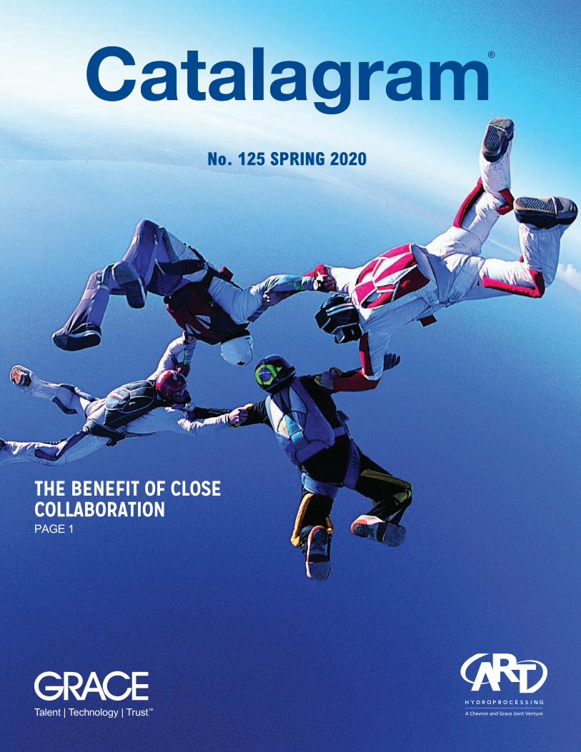
Catalyst Solutions for IMO RulesDon’t let IMO’s 2020 lower global sulfur regulations capsize your profitability. Grace leads the catalysts industry in helping steer potential problems to workable solutions. Let us show you how to leverage Grace’s SOx reduction technologies and LPG olefin additives as part of your FCC strategy.
FCC Catalyst Solutions for IMO 2020 Challenges
Super DESOX® CV+: keep SOx emissions in check while processing FCC feed with higher sulfur content
GBA™ and OlefinsUltra®: maximize feed for alkylation or petrochemical units downstream of the FCC when operating at reduced rates or in LCO mode
Grace has partnered with hundreds of refineries to provide comprehensive catalyst solutions and we’re leading the way in 2020 with current and new technologies designed to provide our customers with a real advantage.
Ask Us How We Do It
grace.com/value
grace.com | 1
The Benefit Of Close Supplier/Refiner Partnerships
Nathan Ergonul Vice President, Marketing, FCC W. R. Grace & Co.
Eboni Adams Director, Marketing Advanced Refining Technologies LLC (ART)
Each calendar year, and in this case, a new decade, gives us new opportunities to respond to and re-evaluate our strategies for growth. Our industry is undergoing major changes; IMO regulation and other regulatory changes and a drive to find more efficient ways to use our resources. Refiners are well aware that we are facing major challenges to continuing to produce the energy that powers our comfortable, modern lifestyles.
At W. R. Grace & Co. and Advanced Refining Technologies LLC (ART), we are fortunate to have a long history of successful partnerships with our customers, which are driven by the commitment we have to this industry and demonstrated by strong technological innovations.
We have built and fostered many close partnerships with our customers and other collaborators, which has proven to be extremely beneficial in creating win-win scenarios. For instance, refiners are maximizing distillate yields to leverage low sulfur fuel oil economics and improve profitability. The ART Hydroprocessing™ portfolio is well positioned to help refiners take advantage of changes brought about by new IMO regulations for marine fuel implemented this year. As refiners seek the flexibility to shift their diesel pool, they want to use more challenging opportunity feedstocks or diesel streams from other refinery units. The article on pg. 31 demonstrates how partnering with ART’s technical experts can help determine a refinery’s optimal catalyst system based on the refiner’s goals and
unit performance. Throughout this issue, you will see excellent examples of such relationships at work.
When we can engage with our customers and go beyond a traditional supplier/customer relationship, we can unlock tremendous value for everyone. We believe that we all will be more prepared to respond to these changes much better if we work closely together. When we collaborate, our industry becomes stronger, innovates faster and smarter, and positions itself to capture more of the opportunities that will come our way in this decade.
As you read this issue, you will find that a common theme runs throughout: a deep collaborative relationship between refiner and supplier. Time and time again, Grace and ART have shown that by working closely together, we can develop catalyst strategies to maximize value for everyone.
On pg. 20, pg. 26, and pg. 39 are articles demonstrating the benefits of working with a trusted catalyst supplier who can provide world-class technical service. In these articles, we show how we employed troubleshooting techniques to increase FCCU catalyst circulation capacity, advanced characterization methods to optimize catalyst utilization in hydrocracking, and evaluation and unit testing to develop a catalyst solution for increased LPG and gasoline yields.
We know the challenges of the future will require new tools, new technologies, and new approaches to succeed. We are working diligently to develop new products through closer engagement
with our customers. We are exploring the capabilities of the new digital tools to quickly identify and respond to changes that will drive more value for the refiners. We strongly believe the refining industry will play a big part in the energy transformation journey. We are working to address your sustainability goals and enable the development of new technology that will take advantage of market trends such as max propylene (pg. 43 and 46).
If you are curious about how a more collaborative relationship with Grace or ART might help you identify opportunities to make 2020 and this decade better for your refinery operations, please get in touch with us.
EDITORIAL
7500 Grace Drive Columbia, MD 21044 USA +1 410.531.4000 grace.com
EXECUTIVE EDITORS:Eboni Adams Nathan Ergonul
MANAGING EDITOR:Shelly DeButts
CONTRIBUTORS:Mohammad Umer Ansari Alvaro Aragon Jonathan Bain Leonardo Betancourt Chad Cavan Wu-Cheng Cheng, Ph.D. Bani Cipriano, Ph.D. Clint Cooper Shelly DeButts Dilip Dharia Eduardo Estrada Christopher Hives Drey Holder David Hunt Ling Jiao Ben Koenigsknecht Kenneth Krug Siyi Lai Theo Maesen Heather Morris Charles Olsen Bob Riley Hyunuk Ryu Woody Shiflett Raj Singh Udayshankar Singh, Ph.D. Phyl Strawley Milton J. Chávez Urdánigo Brian Watkins Bi-Zeng Zhan Mike Ziebarth, Ph.D.
GRAPHIC DESIGN:Lisa Schemm
IN THIS ISSUE of Catalagram®, our experts demonstrate the value of doing
business with Grace. From improved product performance to increased profitability, Grace’s FCC catalysts and additives and ART’s hydroprocessing catalysts and catalysts systems deliver significant value in today’s challenging refining environment.
What’s InsideIN THE NEWS4 TECHNICAL CUSTOMER
SERVICE TEAMS DELIVER VALUE TO FCC CUSTOMERS THROUGH WORKSHOPS
4 JAG REDDY TAPPED TO LEAD ADVANCED REFINING TECHNOLOGIES LLC
5 COMMERCIAL TEAMS PROMOTE CATALYST TECHNOLOGY AROUND THE GLOBE
6 ART HYDROPROCESSING™ CATALYST SOLUTIONS AND EXPERTISE FEATURED AT RESIDHYDROTREAT 2019
7 GARY CHENG NAMED REGIONAL MARKETING MANAGER FOR FCC IN ASIA
7 ART AND HUSKY ENERGY CANADA CELEBRATE 15-YEAR MILESTONE
7 GRACE AND ART OFFER CATALYST TECHNOLOGY SOLUTIONS IN INDIA
8 ART AND CLG HOST WORKSHOP FOR LC-FINING™ (H-OIL) CUSTOMERS
8 UPCOMING EVENTS
SUSTAINABILITY NEWS9 HELPING CUSTOMERS MEET
STRICT ENVIRONMENTAL STANDARDS
DIGITALIZATION NEWS10 DIGITAL TOOLS ADD VALUE
SUCCESS STORIES12 SHELL REFINERY
ACCELERATES BOTTOMS UPGRADING INTO GASOLINE AND DIESEL USING A NOVEL FCC CATALYST SOLUTION
20 SHEPHERDING HYDROCRACKING PROFITABILITY: A NEW APPROACH
26 A CUSTOMER-DRIVEN INNOVATION STORY
31 DISTILLATE POOL MAXIMIZATION BY EXPLOITING THE USE OF OPPORTUNITY FEEDSTOCKS SUCH AS LCO AND SYNTHETIC STOCKS
39 PARKLAND REFINING AND GRACE COLLABORATE TO INCREASE FCCU CATALYST CIRCULATION CAPACITY
43 INTRODUCING PROPYLENEMAX® CATALYTIC CRACKING (PMCC®)
46 ZAVANTI™ CATALYST: NEWEST ZSM-5 TECHNOLOGY FOR MAX PROPYLENE UNITS
© Copyright 2020 W. R. Grace & Co.
WHAT'S INSIDE

grace.com | 3
IN THE NEWSKeeping you up-to-date on Grace FCC and ART Hydroprocessing™ activities
4 | Catalagram® No. 125 | Spring 2020
Technical Customer Service Teams Deliver Value to FCC Customers Through Workshops
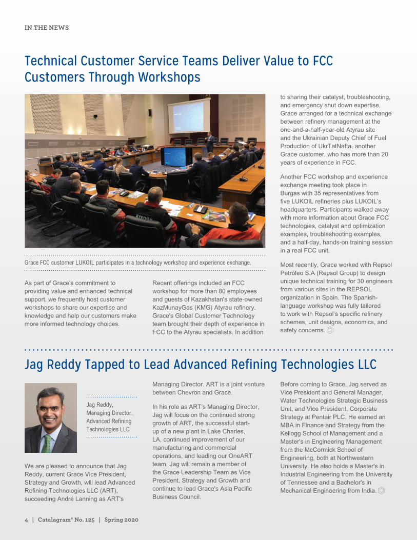
Grace FCC customer LUKOIL participates in a technology workshop and experience exchange.
As part of Grace's commitment to providing value and enhanced technical support, we frequently host customer workshops to share our expertise and knowledge and help our customers make more informed technology choices.
Recent offerings included an FCC workshop for more than 80 employees and guests of Kazakhstan's state-owned KazMunayGas (KMG) Atyrau refinery. Grace's Global Customer Technology team brought their depth of experience in FCC to the Atyrau specialists. In addition
to sharing their catalyst, troubleshooting, and emergency shut down expertise, Grace arranged for a technical exchange between refinery management at the one-and-a-half-year-old Atyrau site and the Ukrainian Deputy Chief of Fuel Production of UkrTatNafta, another Grace customer, who has more than 20 years of experience in FCC.
Another FCC workshop and experience exchange meeting took place in Burgas with 35 representatives from five LUKOIL refineries plus LUKOIL’s headquarters. Participants walked away with more information about Grace FCC technologies, catalyst and optimization examples, troubleshooting examples, and a half-day, hands-on training session in a real FCC unit.
Most recently, Grace worked with Repsol Petróleo S.A (Repsol Group) to design unique technical training for 30 engineers from various sites in the REPSOL organization in Spain. The Spanish-language workshop was fully tailored to work with Repsol’s specific refinery schemes, unit designs, economics, and safety concerns.
Jag Reddy Tapped to Lead Advanced Refining Technologies LLC
Jag Reddy, Managing Director, Advanced Refining Technologies LLC
We are pleased to announce that Jag Reddy, current Grace Vice President, Strategy and Growth, will lead Advanced Refining Technologies LLC (ART), succeeding André Lanning as ART's
Managing Director. ART is a joint venture between Chevron and Grace.
In his role as ART’s Managing Director, Jag will focus on the continued strong growth of ART, the successful start-up of a new plant in Lake Charles, LA, continued improvement of our manufacturing and commercial operations, and leading our OneART team. Jag will remain a member of the Grace Leadership Team as Vice President, Strategy and Growth and continue to lead Grace's Asia Pacific Business Council.
Before coming to Grace, Jag served as Vice President and General Manager, Water Technologies Strategic Business Unit, and Vice President, Corporate Strategy at Pentair PLC. He earned an MBA in Finance and Strategy from the Kellogg School of Management and a Master's in Engineering Management from the McCormick School of Engineering, both at Northwestern University. He also holds a Master's in Industrial Engineering from the University of Tennessee and a Bachelor's in Mechanical Engineering from India.
IN THE NEWS
grace.com | 5
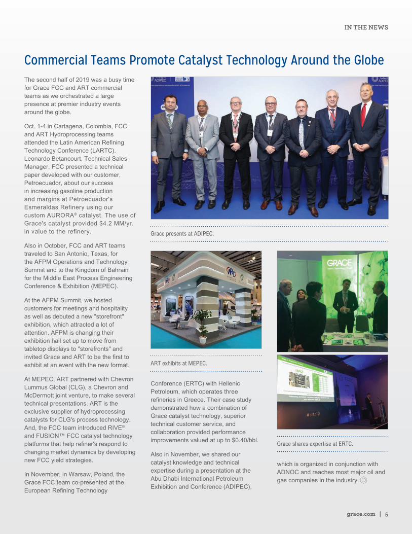
Commercial Teams Promote Catalyst Technology Around the GlobeThe second half of 2019 was a busy time for Grace FCC and ART commercial teams as we orchestrated a large presence at premier industry events around the globe.
Oct. 1-4 in Cartagena, Colombia, FCC and ART Hydroprocessing teams attended the Latin American Refining Technology Conference (LARTC). Leonardo Betancourt, Technical Sales Manager, FCC presented a technical paper developed with our customer, Petroecuador, about our success in increasing gasoline production and margins at Petroecuador's Esmeraldas Refinery using our custom AURORA® catalyst. The use of Grace's catalyst provided $4.2 MM/yr. in value to the refinery.
Also in October, FCC and ART teams traveled to San Antonio, Texas, for the AFPM Operations and Technology Summit and to the Kingdom of Bahrain for the Middle East Process Engineering Conference & Exhibition (MEPEC).
At the AFPM Summit, we hosted customers for meetings and hospitality as well as debuted a new "storefront" exhibition, which attracted a lot of attention. AFPM is changing their exhibition hall set up to move from tabletop displays to "storefronts" and invited Grace and ART to be the first to exhibit at an event with the new format.
At MEPEC, ART partnered with Chevron Lummus Global (CLG), a Chevron and McDermott joint venture, to make several technical presentations. ART is the exclusive supplier of hydroprocessing catalysts for CLG's process technology. And, the FCC team introduced RIVE® and FUSION™ FCC catalyst technology platforms that help refiner's respond to changing market dynamics by developing new FCC yield strategies.
In November, in Warsaw, Poland, the Grace FCC team co-presented at the European Refining Technology
Grace presents at ADIPEC.
ART exhibits at MEPEC.
Conference (ERTC) with Hellenic Petroleum, which operates three refineries in Greece. Their case study demonstrated how a combination of Grace catalyst technology, superior technical customer service, and collaboration provided performance improvements valued at up to $0.40/bbl.
Also in November, we shared our catalyst knowledge and technical expertise during a presentation at the Abu Dhabi International Petroleum Exhibition and Conference (ADIPEC),
Grace shares expertise at ERTC.
which is organized in conjunction with ADNOC and reaches most major oil and gas companies in the industry.
IN THE NEWS
6 | Catalagram® No. 125 | Spring 2020
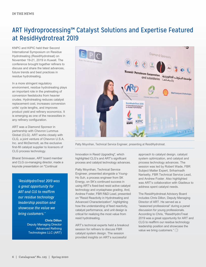
ART Hydroprocessing™ Catalyst Solutions and Expertise Featured at ResidHydrotreat 2019KNPC and KIPIC held their Second International Symposium on Residue Hydrotreating (ResidHydrotreat) on November 19-21, 2019 in Kuwait. The conference brought together refiners to discuss and share the latest advances, future trends and best practices in residue hydrotreating.
In a more stringent regulatory environment, residue hydrotreating plays an important role in the pretreating of conversion feedstocks from heavier crudes. Hydrotreating reduces catalyst replacement cost, increases conversion units’ cycle lengths, and improves product yield and refinery economics. It is emerging as one of the necessities in any refinery configuration.
ART was a Diamond Sponsor in partnership with Chevron Lummus Global (CLG). ART works closely with CLG, a joint venture of Chevron U.S.A. Inc. and McDermott, as the exclusive first-fill catalyst supplier to licensors of CLG process technology.
Bharat Srinivasan, ART board member and CLG co-managing director, made a keynote presentation on "Continual
“ResidHydroTreat 2019 was a great opportunity for ART and CLG to reaffirm our residue technology leadership position and showcase the value we
bring customers.”
Chris Dillon Deputy Managing Director
Advanced Refining Technologies LLC (ART)
Patty Moynihan, Technical Service Engineer, presenting at ResidHydrotreat.
Innovation in Resid Upgrading", which highlighted CLG’s and ART’s significant process and catalyst technology advances.
Patty Moynihan, Technical Service Engineer, presented alongside a Young-Ho Suh, a process engineer from SK Energy, on SK’s continued success in using ART’s fixed-bed resid active catalyst technology and crystaphase grading. And, Andrew Foster, FBR R&D Lead, presented on "Resid Reactivity in Hydrotreating and Advanced Characterization", highlighting how the understanding of feed reactivity, catalyst performance, and unit design is critical for realizing the most value from resid hydrotreating.
ART’s technical experts held a breakout session for refiners to discuss FBR catalyst system design. The session provided insights on ART’s successful
approach to catalyst design, catalyst system optimization, and catalyst and process technology advances. The session was led by Robert Wade, FBR Subject Matter Expert, Sriharinadh Narisetty, FBR Technical Service Lead, and Andrew Foster. Also highlighted was ART’s collaboration with Gladieux to address spent catalyst needs.
The ResidHydrotreat Advisory Board includes Chris Dillon, Deputy Managing Director of ART. He served as a “seasoned professional” during a panel discussion for young professionals. According to Chris, “ResidHydroTreat 2019 was a great opportunity for ART and CLG to reaffirm our residue technology leadership position and showcase the value we bring customers.”
IN THE NEWS
grace.com | 7
Gary Cheng Named Regional Marketing Manager for FCC in Asia
Gary Cheng, Regional Marketing Manager, FCC, Asia Pacific, W. R. Grace & Co.
Gary Cheng has been promoted to Regional Marketing Manager, FCC, Asia Pacific, based in Singapore. In his new role, Gary is responsible for leading FCC marketing initiatives across the Asia Pacific region.
Gary joined Grace in 2014 as an FCC Technical Service Manager providing
support to various North America refineries. In 2017, he moved into a Technical Sales Manager role and has grown revenues consistently year over year, most recently with several refining companies including PES, PBF, Husky Energy, and ExxonMobil. Gary has presented at various industry conferences on behalf of Grace.
ART and Husky Energy Canada Celebrate 15-year MilestoneOn Oct. 8, in celebration of 15 years of continuous supply of Ebullating Bed Resid catalysts to the H-Oil unit of Husky Energy's Lloydminster site in Alberta, Canada, ART presented a commemorative plaque to Husky site General Manager Kent Miller.
Over dinner for Husky’s leadership team hosted by ART, Kent Miller, who has been with Husky for the past 10 years, commented on the value delivered by each catalyst change implemented by ART for Husky and expressed his
appreciation for the high quality of technical support his team has received. To top off this milestone anniversary, ART was just awarded a new multi-year supply agreement from Husky.
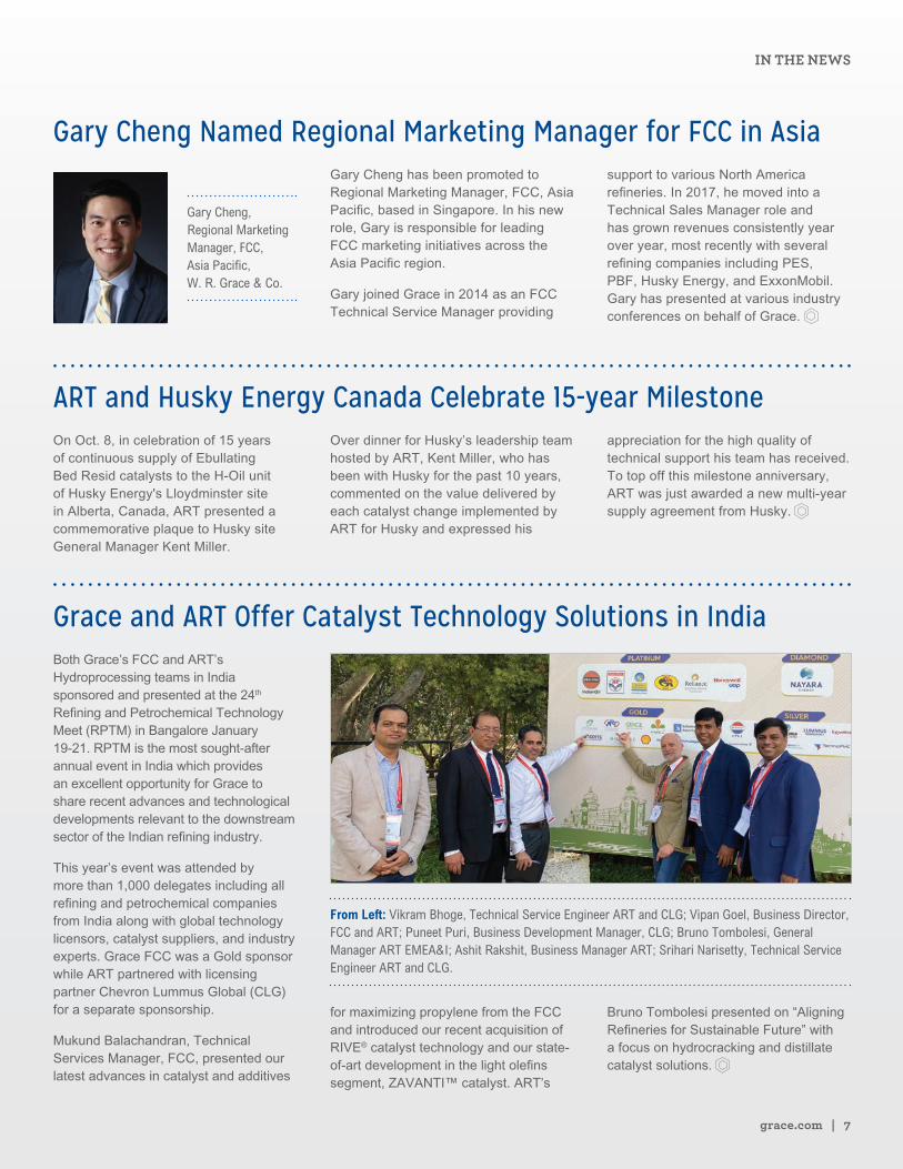
Grace and ART Offer Catalyst Technology Solutions in IndiaBoth Grace’s FCC and ART’s Hydroprocessing teams in India sponsored and presented at the 24th Refining and Petrochemical Technology Meet (RPTM) in Bangalore January 19-21. RPTM is the most sought-after annual event in India which provides an excellent opportunity for Grace to share recent advances and technological developments relevant to the downstream sector of the Indian refining industry.
This year’s event was attended by more than 1,000 delegates including all refining and petrochemical companies from India along with global technology licensors, catalyst suppliers, and industry experts. Grace FCC was a Gold sponsor while ART partnered with licensing partner Chevron Lummus Global (CLG) for a separate sponsorship.
Mukund Balachandran, Technical Services Manager, FCC, presented our latest advances in catalyst and additives
From Left: Vikram Bhoge, Technical Service Engineer ART and CLG; Vipan Goel, Business Director, FCC and ART; Puneet Puri, Business Development Manager, CLG; Bruno Tombolesi, General Manager ART EMEA&I; Ashit Rakshit, Business Manager ART; Srihari Narisetty, Technical Service Engineer ART and CLG.
for maximizing propylene from the FCC and introduced our recent acquisition of RIVE® catalyst technology and our state-of-art development in the light olefins segment, ZAVANTI™ catalyst. ART’s
Bruno Tombolesi presented on “Aligning Refineries for Sustainable Future” with a focus on hydrocracking and distillate catalyst solutions.
IN THE NEWS
8 | Catalagram® No. 125 | Spring 2020
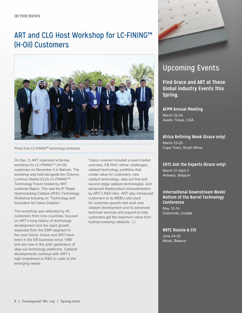
ART and CLG Host Workshop for LC-FINING™ (H-Oil) Customers
Photo from LC-FINING™ technology workshop.
On Dec. 5, ART organized a full-day workshop for LC-FINING™ (H-Oil) customers on December 5 in Bahrain. The workshop was held alongside the Chevron Lummus Global (CLG) LC-FINING™ Technology Forum hosted by ART customer Bapco. This was the 6th Resid Hydrocracking Catalyst (RHC) Technology Workshop focusing on “Technology and Innovation for Value Creation.”
The workshop was attended by 40 customers from nine countries, focused on ART’s long history of technology development and the rapid growth expected from the EBR segment in the near future. Grace and ART have been in the EB business since 1986 and are now in the sixth generation of step-out technology platforms. Catalyst developments continue with ART’s high investment to R&D to cater to the emerging needs.
Topics covered included a resid market overview, EB RHC refiner challenges, catalyst technology portfolios that create value for customers, new catalyst technology, step-out first and second stage catalyst technologies, and advanced feed/product characterization by ART’s R&D labs. ART also introduced customers to its MEBU pilot plant for customer-specific test work and catalyst development and its advanced technical services and support to help customers get the maximum value from hydroprocessing catalysts.
Upcoming Events
Find Grace and ART at These Global industry Events This Spring.
AFPM Annual MeetingMarch 22-24 Austin, Texas, USA
Africa Refining Week (Grace only)March 23-25 Cape Town, South Africa
ERTC Ask the Experts (Grace only)March 31-April 2 Antwerp, Belgium
International Downstream Week/Bottom of the Barrel Technology ConferenceMay 12-14 Dubrovnik, Croatia
BBTC Russia & CISJune 24-25 Minsk, Belarus
IN THE NEWS
grace.com | 9
Many companies in our industry are keenly focused on measuring and reducing the negative environmental impacts from refining operations, including Grace and ART, our joint venture with Chevron. We contribute to our customers’ sustainability goals by developing and producing catalysts, additives, and other engineered materials that help refiners reduce emissions, meet stricter environmental standards, improve energy efficiency in their operations, and provide flexibility for processing diverse feedstocks. Approximately $358MM* in sales at Grace is generated from products such as:
• FCC additives that help reduce SOx and NOx emissions
• ART Hydroprocessing catalysts that help meet cleaner fuel standards such as IMO 2020 low-sulfur marine fuel regulations
• Colloidal silicas used in vehicle emission control devices and as a process aid for biodiesel
In addition, novel pathways are being developed for producing advanced biofuels via catalysis. Uncertainty surrounding the regulatory environment in the U.S. and European regulations such as BREF are driving more interest in biofuels, but success in this market is dependent on overcoming the economic
hurdle of biomass conversion. Grace produces catalysts designed to help overcome biomass conversion and renewable technology challenges. With Grace's customized solutions, biorefining becomes simpler, faster and more efficient.
Grace's broad portfolio of fluid catalytic cracking (FCC) catalysts includes technology designed to maximize the efficiency of the FCC unit above the industry average. Optimizing refinery operations reduces both energy and raw material use per unit of output. Products such as advanced FCC catalysts to
reduce raw material and energy requirements and advanced silica gel to reduce water use and waste in other manufacturing processes accounts for approximately $500MM* in sales.
As part of the process of developing new products, we assess potential health and safety risks, regulatory requirements, how to train our personnel and end-users to use the product safely and handle waste, and how to transport the product with no impact to the environment. For each new catalyst innovation, we also consider sustainability issues surrounding efficient use of natural resources and energy, whether we can use a less hazardous raw materials, and the full life cycle of the product, including disposal and recycling.
As our customers' needs for more sustainable products and processes have increased, so too has Grace's focus on integrating sustainability into the design, functionality, and value propositions of our products.
SUSTAINABILITY NEWS
Helping Customers Meet Strict Environmental Standards Shelly DeButts Marketing Communications Manager Refining Technologies W. R. Grace & Co.
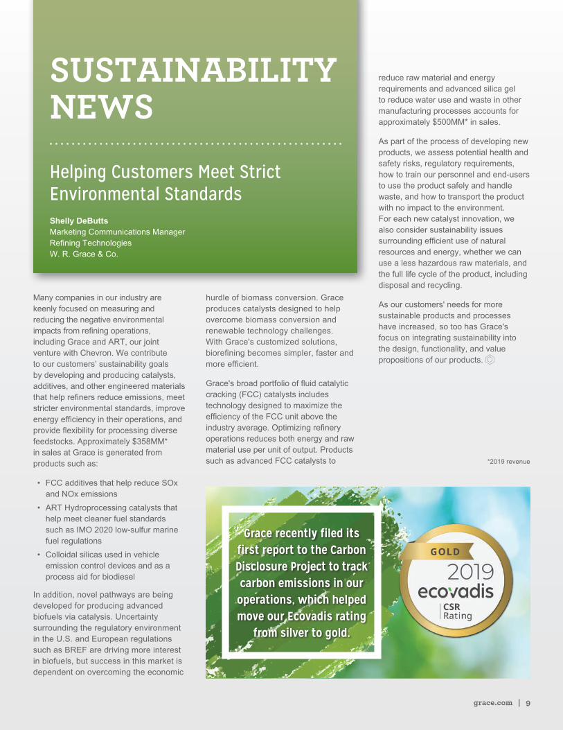
Grace recently filed its first report to the Carbon Disclosure Project to track carbon emissions in our operations, which helped move our Ecovadis rating
from silver to gold.
*2019 revenue
10 | Catalagram® No. 125 | Spring 2020
Grace’s digital transformation strategy is a customer-driven plan for ensuring the right capabilities are developed at the right time to continue to add value to our customers’ operations, differentiating ourselves from other catalyst suppliers. We believe that digitalization should be viewed as a support tool, not a driver. Digital tools can add unique value for identifying opportunities, and enabling those opportunities to be captured as quickly as possible. The benefits of digital tools are compliments to traditional value drivers in FCC, including, leading catalyst and additive technologies, strong supply flexibility, and excellent technical support. Combining digital tools with these existing attributes allows Grace to continue to provide the best-in-class value creation platform.
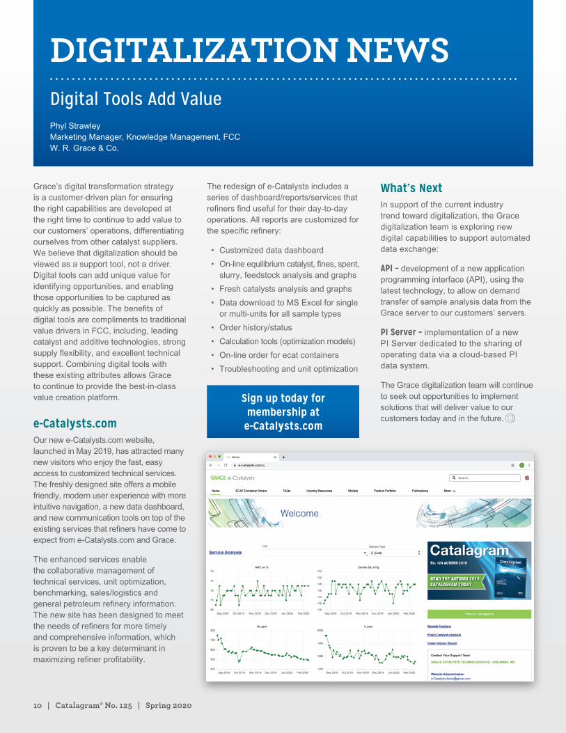
e-Catalysts.com Our new e-Catalysts.com website, launched in May 2019, has attracted many new visitors who enjoy the fast, easy access to customized technical services. The freshly designed site offers a mobile friendly, modern user experience with more intuitive navigation, a new data dashboard, and new communication tools on top of the existing services that refiners have come to expect from e-Catalysts.com and Grace.
The enhanced services enable the collaborative management of technical services, unit optimization, benchmarking, sales/logistics and general petroleum refinery information. The new site has been designed to meet the needs of refiners for more timely and comprehensive information, which is proven to be a key determinant in maximizing refiner profitability.
The redesign of e-Catalysts includes a series of dashboard/reports/services that refiners find useful for their day-to-day operations. All reports are customized for the specific refinery:
• Customized data dashboard
• On-line equilibrium catalyst, fines, spent, slurry, feedstock analysis and graphs
• Fresh catalysts analysis and graphs
• Data download to MS Excel for single or multi-units for all sample types
• Order history/status
• Calculation tools (optimization models)
• On-line order for ecat containers
• Troubleshooting and unit optimization
Sign up today for membership at
e-Catalysts.com
What’s Next In support of the current industry trend toward digitalization, the Grace digitalization team is exploring new digital capabilities to support automated data exchange:
API – development of a new application programming interface (API), using the latest technology, to allow on demand transfer of sample analysis data from the Grace server to our customers’ servers.
PI Server – implementation of a new PI Server dedicated to the sharing of operating data via a cloud-based PI data system.
The Grace digitalization team will continue to seek out opportunities to implement solutions that will deliver value to our customers today and in the future.
DIGITALIZATION NEWSDigital Tools Add ValuePhyl Strawley Marketing Manager, Knowledge Management, FCC W. R. Grace & Co.

SUCCESS STORIES
Shell Refinery Accelerates Bottoms Upgrading into Gasoline and Diesel Using a Novel FCC Catalyst Solution
Heather Morris FCC Operations Support Engineer Shell Canada Ltd.
Mohammad Umer Ansari Senior Technologist, Catalytic Cracking Shell Global Solutions US Inc.
Clint Cooper FCC Technical Services Manager W. R. Grace & Co.
Maximizing diffusion of feed into and products out of an FCC
catalyst is critical to unlocking the full value potential of an FCC
unit in which the riser residence time is only a few seconds. RIVE®
FCC catalysts incorporate Molecular Highway® Y-zeolite (MHY™)
technology, which engineers a precise series of mesopores into
the Y-zeolite framework, the primary active component of all FCC
catalysts. This technology enhances diffusion of molecules into
and out of the catalyst.
Building on the continued success of Rive Technology (Rive) and
W. R. Grace & Co. (Grace) at a Shell U.S. Gulf Coast (USGC) refinery
in 2016 [1], a customized catalyst solution incorporating MHY™
zeolite was designed and trialed at a second North American Shell
refinery. The primary objective of this trial was to increase FCC
bottoms upgrading into valuable gasoline and diesel products.
The trial results again demonstrated the significant value that this
technology can provide to an FCC unit. During the trial, Shell was
able to realize uplift in the range of $1.45 to $1.80 /BBLFF (within the
boundary of the FCC unit) depending on the market economics.
This article will further investigate Molecular Highway® Y-zeolite
technology and how it was successfully used to improve
performance at this refinery.
grace.com | 13
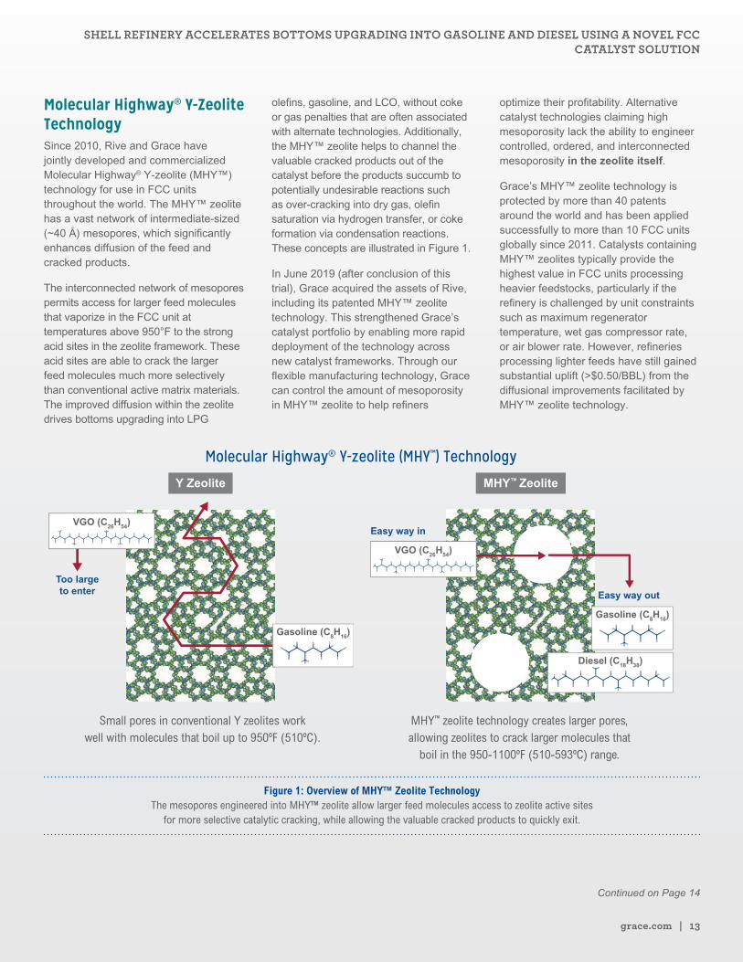
Molecular Highway® Y-Zeolite TechnologySince 2010, Rive and Grace have jointly developed and commercialized Molecular Highway® Y-zeolite (MHY™) technology for use in FCC units throughout the world. The MHY™ zeolite has a vast network of intermediate-sized (~40 Å) mesopores, which significantly enhances diffusion of the feed and cracked products.
The interconnected network of mesopores permits access for larger feed molecules that vaporize in the FCC unit at temperatures above 950°F to the strong acid sites in the zeolite framework. These acid sites are able to crack the larger feed molecules much more selectively than conventional active matrix materials. The improved diffusion within the zeolite drives bottoms upgrading into LPG
olefins, gasoline, and LCO, without coke or gas penalties that are often associated with alternate technologies. Additionally, the MHY™ zeolite helps to channel the valuable cracked products out of the catalyst before the products succumb to potentially undesirable reactions such as over-cracking into dry gas, olefin saturation via hydrogen transfer, or coke formation via condensation reactions. These concepts are illustrated in Figure 1.
In June 2019 (after conclusion of this trial), Grace acquired the assets of Rive, including its patented MHY™ zeolite technology. This strengthened Grace’s catalyst portfolio by enabling more rapid deployment of the technology across new catalyst frameworks. Through our flexible manufacturing technology, Grace can control the amount of mesoporosity in MHY™ zeolite to help refiners
optimize their profitability. Alternative catalyst technologies claiming high mesoporosity lack the ability to engineer controlled, ordered, and interconnected mesoporosity in the zeolite itself.
Grace’s MHY™ zeolite technology is protected by more than 40 patents around the world and has been applied successfully to more than 10 FCC units globally since 2011. Catalysts containing MHY™ zeolites typically provide the highest value in FCC units processing heavier feedstocks, particularly if the refinery is challenged by unit constraints such as maximum regenerator temperature, wet gas compressor rate, or air blower rate. However, refineries processing lighter feeds have still gained substantial uplift (>$0.50/BBL) from the diffusional improvements facilitated by MHY™ zeolite technology.
Molecular Highway® Y-zeolite (MHY™) Technology
Small pores in conventional Y zeolites work well with molecules that boil up to 950ºF (510ºC).
MHY™ zeolite technology creates larger pores, allowing zeolites to crack larger molecules that
boil in the 950-1100ºF (510-593ºC) range.
Y Zeolite
Too largeto enter
VGO (C26H54)
Gasoline (C8H16)
MHY™ Zeolite
Easy way in
VGO (C26H54)
Diesel (C18H38)
Easy way out
Gasoline (C8H16)
Figure 1: Overview of MHY™ Zeolite Technology The mesopores engineered into MHY™ zeolite allow larger feed molecules access to zeolite active sites
for more selective catalytic cracking, while allowing the valuable cracked products to quickly exit.
Continued on Page 14
SHELL REFINERY ACCELERATES BOTTOMS UPGRADING INTO GASOLINE AND DIESEL USING A NOVEL FCC CATALYST SOLUTION
14 | Catalagram® No. 125 | Spring 2020
The catalyst used at this Shell refinery was customized to meet the specific objectives and constraints – namely, using improved diffusion to upgrade slurry into valuable gasoline plus distillate.
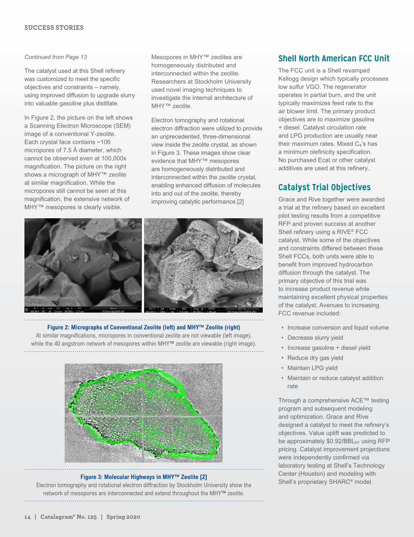
In Figure 2, the picture on the left shows a Scanning Electron Microscope (SEM) image of a conventional Y-zeolite. Each crystal face contains ~106 micropores of 7.5 Å diameter, which cannot be observed even at 100,000x magnification. The picture on the right shows a micrograph of MHY™ zeolite at similar magnification. While the micropores still cannot be seen at this magnification, the extensive network of MHY™ mesopores is clearly visible.
Mesopores in MHY™ zeolites are homogeneously distributed and interconnected within the zeolite. Researchers at Stockholm University used novel imaging techniques to investigate the internal architecture of MHY™ zeolite.
Electron tomography and rotational electron diffraction were utilized to provide an unprecedented, three-dimensional view inside the zeolite crystal, as shown in Figure 3. These images show clear evidence that MHY™ mesopores are homogeneously distributed and interconnected within the zeolite crystal, enabling enhanced diffusion of molecules into and out of the zeolite, thereby improving catalytic performance.[2]
Figure 2: Micrographs of Conventional Zeolite (left) and MHY™ Zeolite (right) At similar magnifications, micropores in conventional zeolite are not viewable (left image),
while the 40 angstrom network of mesopores within MHY™ zeolite are viewable (right image).
Figure 3: Molecular Highways in MHY™ Zeolite [2] Electron tomography and rotational electron diffraction by Stockholm University show the
network of mesopores are interconnected and extend throughout the MHY™ zeolite.
Shell North American FCC UnitThe FCC unit is a Shell revamped Kellogg design which typically processes low sulfur VGO. The regenerator operates in partial burn, and the unit typically maximizes feed rate to the air blower limit. The primary product objectives are to maximize gasoline + diesel. Catalyst circulation rate and LPG production are usually near their maximum rates. Mixed C4’s has a minimum olefinicity specification. No purchased Ecat or other catalyst additives are used at this refinery.
Catalyst Trial ObjectivesGrace and Rive together were awarded a trial at the refinery based on excellent pilot testing results from a competitive RFP and proven success at another Shell refinery using a RIVE® FCC catalyst. While some of the objectives and constraints differed between these Shell FCCs, both units were able to benefit from improved hydrocarbon diffusion through the catalyst. The primary objective of this trial was to increase product revenue while maintaining excellent physical properties of the catalyst. Avenues to increasing FCC revenue included:
• Increase conversion and liquid volume
• Decrease slurry yield
• Increase gasoline + diesel yield
• Reduce dry gas yield
• Maintain LPG yield
• Maintain or reduce catalyst addition rate
Through a comprehensive ACE™ testing program and subsequent modeling and optimization, Grace and Rive designed a catalyst to meet the refinery’s objectives. Value uplift was predicted to be approximately $0.92/BBLFF using RFP pricing. Catalyst improvement projections were independently confirmed via laboratory testing at Shell’s Technology Center (Houston) and modeling with Shell’s proprietary SHARC® model.
Continued from Page 13
SUCCESS STORIES
grace.com | 15
Trial analysis and evaluation was a joint team effort by Rive, Grace, Shell’s technology group, and the refinery personnel. Several different methods were used to analyze the trial and determine the catalyst’s uplift, including:
• Operating Data Evaluation (cross-plots; comparing similar time periods)
• Ecat Data Evaluation (cross-plots; ACE™ testing at before and after Ecat turn-over to the RIVE® FCC catalyst)
• FCC Kinetic Modeling
Risk Mitigation and Technical ServicePrior to the trial, the combined team worked closely to create a risk management plan. Key risk management items included:
• Ensuring C4 olefinicity remained above minimum specifications
• No increase to catalyst attrition/losses
• Regenerator bed temperature would remain within specified limits
For each risk, the team created a detailed monitoring plan and mitigation plan. Near the start of each review throughout the trial, each of these risk management items was discussed. With the high level of attention and review frequency, each item was maintained or improved during the trial.
Collaboration between Rive, Grace, Shell’s technology group, and the refinery personnel ensured a successful trial. The entire team worked to push the unit to significantly improved profitability, by leveraging the catalyst’s benefits at optimized operating conditions. Grace was also able to utilize the technical expertise from its Global Customer Technology group to assist with fine tuning operating variables during the trial.
Evaluating Operating DataThe combined team monitored daily operating data throughout the trial to evaluate the effects of the catalyst change. Updated process data was
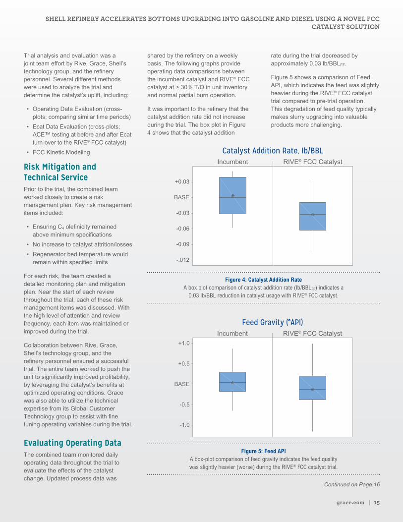
shared by the refinery on a weekly basis. The following graphs provide operating data comparisons between the incumbent catalyst and RIVE® FCC catalyst at > 30% T/O in unit inventory and normal partial burn operation.
It was important to the refinery that the catalyst addition rate did not increase during the trial. The box plot in Figure 4 shows that the catalyst addition
rate during the trial decreased by approximately 0.03 lb/BBLFF.
Figure 5 shows a comparison of Feed API, which indicates the feed was slightly heavier during the RIVE® FCC catalyst trial compared to pre-trial operation. This degradation of feed quality typically makes slurry upgrading into valuable products more challenging.
Catalyst Addition Rate, Ib/BBLIncumbent RIVE® FCC Catalyst
+0.03
BASE
-0.03
-0.09
-0.06
-.012
Figure 4: Catalyst Addition Rate A box plot comparison of catalyst addition rate (lb/BBLFF) indicates a
0.03 lb/BBL reduction in catalyst usage with RIVE® FCC catalyst.
Feed Gravity (°API)Incumbent RIVE® FCC Catalyst
+1.0
+0.5
BASE
-0.5
-1.0
Figure 5: Feed API A box-plot comparison of feed gravity indicates the feed quality was slightly heavier (worse) during the RIVE® FCC catalyst trial.
Continued on Page 16
SHELL REFINERY ACCELERATES BOTTOMS UPGRADING INTO GASOLINE AND DIESEL USING A NOVEL FCC CATALYST SOLUTION
16 | Catalagram® No. 125 | Spring 2020
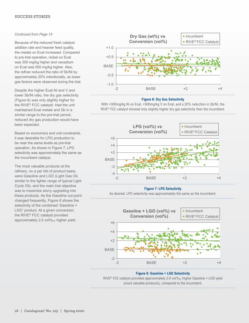
Because of the reduced fresh catalyst addition rate and heavier feed quality, the metals on Ecat increased. Compared to pre-trial operation, nickel on Ecat was 300 mg/kg higher and vanadium on Ecat was 500 mg/kg higher. Also, the refiner reduced the ratio of Sb/Ni by approximately 20% intentionally, as lower gas factors were observed during the trial.
Despite the higher Ecat Ni and V and lower Sb/Ni ratio, the dry gas selectivity (Figure 6) was only slightly higher for the RIVE® FCC catalyst. Had the unit maintained Ecat metals and Sb in a similar range to the pre-trial period, reduced dry gas production would have been expected.
Based on economics and unit constraints, it was desirable for LPG production to be near the same levels as pre-trial operation. As shown in Figure 7, LPG selectivity was approximately the same as the incumbent catalyst.
The most valuable products at the refinery, on a per bbl of product basis, were Gasoline and LGO (Light Gas Oil, similar to the lighter range of typical Light Cycle Oil), and the main trial objective was to maximize slurry upgrading into these products. As the Gasoline cut-point changed frequently, Figure 8 shows the selectivity of the combined ‘Gasoline + LGO’ product. At a given conversion, the RIVE® FCC catalyst provided approximately 2.0 vol%FF higher yield.
Dry Gas (wt%) vs Conversion (vol%)
+1.0
+0.5
BASE
-0.5
-1.0-2 BASE +2 +4
Incumbent
RIVE® FCC Catalyst
Figure 6: Dry Gas Selectivity With +300mg/kg Ni on Ecat, +500mg/kg V on Ecat, and a 20% reduction in Sb/Ni, the RIVE® FCC catalyst showed only slightly higher dry gas selectivity than the incumbent.
LPG (vol%) vs Conversion (vol%)
+6
+4
+2
BASE
-2
-4-2 BASE +2 +4
Incumbent
RIVE® FCC Catalyst
Figure 7: LPG Selectivity As desired, LPG selectivity was approximately the same as the incumbent.
Gasoline + LGO (vol%) vsConversion (vol%)
+6
+4
+2
BASE
-2-2 BASE +2 +4
Incumbent
RIVE® FCC Catalyst
Figure 8: Gasoline + LGO Selectivity RIVE® FCC catalyst provided approximately 2.0 vol%FF higher Gasoline + LGO yield
(most valuable products), compared to the incumbent.
Continued from Page 15
SUCCESS STORIES
grace.com | 17
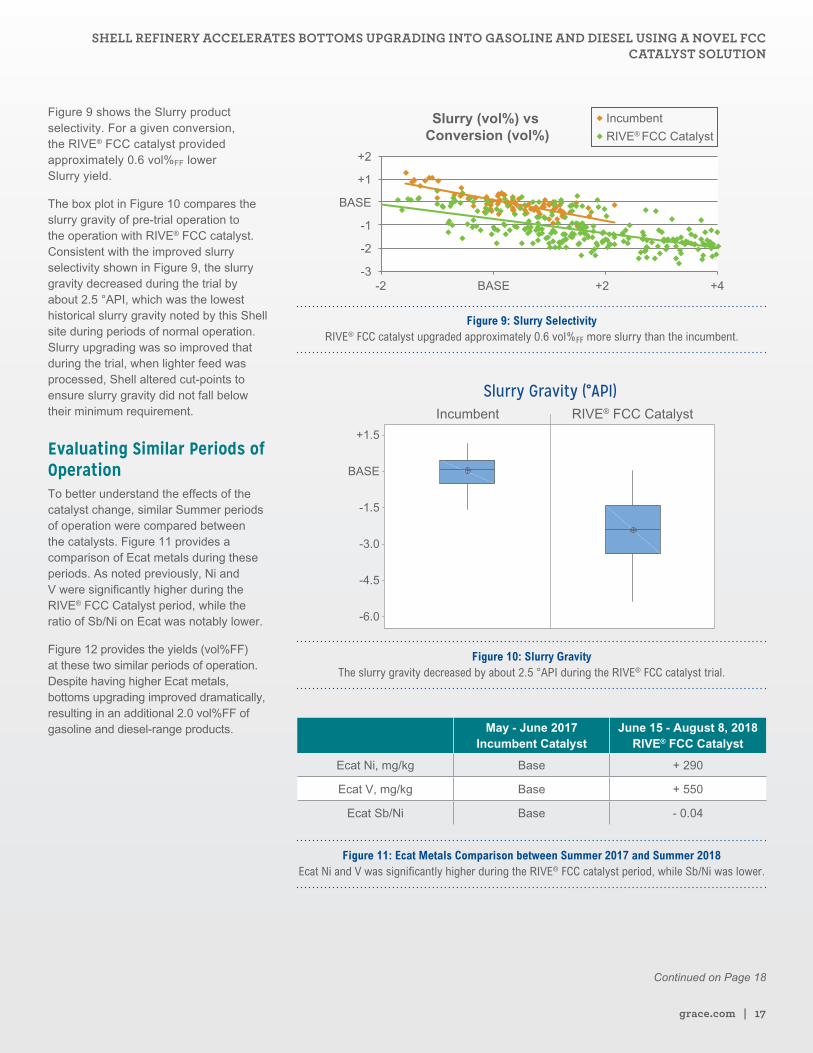
Figure 9 shows the Slurry product selectivity. For a given conversion, the RIVE® FCC catalyst provided approximately 0.6 vol%FF lower Slurry yield.
The box plot in Figure 10 compares the slurry gravity of pre-trial operation to the operation with RIVE® FCC catalyst. Consistent with the improved slurry selectivity shown in Figure 9, the slurry gravity decreased during the trial by about 2.5 °API, which was the lowest historical slurry gravity noted by this Shell site during periods of normal operation. Slurry upgrading was so improved that during the trial, when lighter feed was processed, Shell altered cut-points to ensure slurry gravity did not fall below their minimum requirement.
Evaluating Similar Periods of OperationTo better understand the effects of the catalyst change, similar Summer periods of operation were compared between the catalysts. Figure 11 provides a comparison of Ecat metals during these periods. As noted previously, Ni and V were significantly higher during the RIVE® FCC Catalyst period, while the ratio of Sb/Ni on Ecat was notably lower.
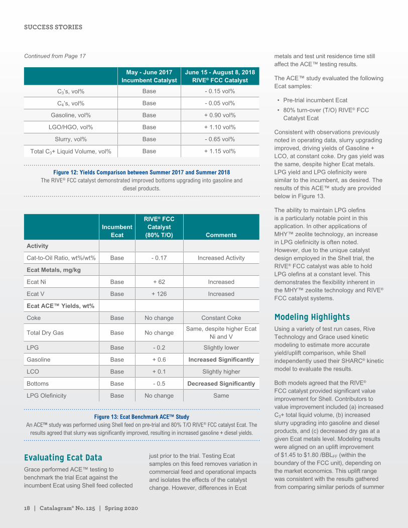
Figure 12 provides the yields (vol%FF) at these two similar periods of operation. Despite having higher Ecat metals, bottoms upgrading improved dramatically, resulting in an additional 2.0 vol%FF of gasoline and diesel-range products.
Slurry (vol%) vs Conversion (vol%)
+2
+1
-1
BASE
-2
-3-2 BASE +2 +4
Incumbent
RIVE® FCC Catalyst
Figure 9: Slurry Selectivity RIVE® FCC catalyst upgraded approximately 0.6 vol%FF more slurry than the incumbent.
Slurry Gravity (°API)Incumbent RIVE® FCC Catalyst
+1.5
BASE
-1.5
-4.5
-3.0
-6.0
Figure 10: Slurry Gravity The slurry gravity decreased by about 2.5 °API during the RIVE® FCC catalyst trial.
May - June 2017 Incumbent Catalyst
June 15 - August 8, 2018 RIVE® FCC Catalyst
Ecat Ni, mg/kg Base + 290
Ecat V, mg/kg Base + 550
Ecat Sb/Ni Base - 0.04
Figure 11: Ecat Metals Comparison between Summer 2017 and Summer 2018 Ecat Ni and V was significantly higher during the RIVE® FCC catalyst period, while Sb/Ni was lower.
Continued on Page 18
SHELL REFINERY ACCELERATES BOTTOMS UPGRADING INTO GASOLINE AND DIESEL USING A NOVEL FCC CATALYST SOLUTION
18 | Catalagram® No. 125 | Spring 2020
May - June 2017 Incumbent Catalyst
June 15 - August 8, 2018 RIVE® FCC Catalyst
C3’s, vol% Base - 0.15 vol%
C4’s, vol% Base - 0.05 vol%
Gasoline, vol% Base + 0.90 vol%
LGO/HGO, vol% Base + 1.10 vol%
Slurry, vol% Base - 0.65 vol%
Total C3+ Liquid Volume, vol% Base + 1.15 vol%
Figure 12: Yields Comparison between Summer 2017 and Summer 2018 The RIVE® FCC catalyst demonstrated improved bottoms upgrading into gasoline and
diesel products.
Incumbent Ecat
RIVE® FCC Catalyst
(80% T/O) Comments
Activity
Cat-to-Oil Ratio, wt%/wt% Base - 0.17 Increased Activity
Ecat Metals, mg/kg
Ecat Ni Base + 62 Increased
Ecat V Base + 126 Increased
Ecat ACE™ Yields, wt%
Coke Base No change Constant Coke
Total Dry Gas Base No changeSame, despite higher Ecat
Ni and V
LPG Base - 0.2 Slightly lower
Gasoline Base + 0.6 Increased Significantly
LCO Base + 0.1 Slightly higher
Bottoms Base - 0.5 Decreased Significantly
LPG Olefinicity Base No change Same
Figure 13: Ecat Benchmark ACE™ Study An ACE™ study was performed using Shell feed on pre-trial and 80% T/O RIVE® FCC catalyst Ecat. The
results agreed that slurry was significantly improved, resulting in increased gasoline + diesel yields.
Evaluating Ecat DataGrace performed ACE™ testing to benchmark the trial Ecat against the incumbent Ecat using Shell feed collected
just prior to the trial. Testing Ecat samples on this feed removes variation in commercial feed and operational impacts and isolates the effects of the catalyst change. However, differences in Ecat
metals and test unit residence time still affect the ACE™ testing results.
The ACE™ study evaluated the following Ecat samples:
• Pre-trial incumbent Ecat
• 80% turn-over (T/O) RIVE® FCC Catalyst Ecat
Consistent with observations previously noted in operating data, slurry upgrading improved, driving yields of Gasoline + LCO, at constant coke. Dry gas yield was the same, despite higher Ecat metals. LPG yield and LPG olefinicity were similar to the incumbent, as desired. The results of this ACE™ study are provided below in Figure 13.
The ability to maintain LPG olefins is a particularly notable point in this application. In other applications of MHY™ zeolite technology, an increase in LPG olefinicity is often noted. However, due to the unique catalyst design employed in the Shell trial, the RIVE® FCC catalyst was able to hold LPG olefins at a constant level. This demonstrates the flexibility inherent in the MHY™ zeolite technology and RIVE® FCC catalyst systems.
Modeling HighlightsUsing a variety of test run cases, Rive Technology and Grace used kinetic modeling to estimate more accurate yield/uplift comparison, while Shell independently used their SHARC® kinetic model to evaluate the results.
Both models agreed that the RIVE® FCC catalyst provided significant value improvement for Shell. Contributors to value improvement included (a) increased C3+ total liquid volume, (b) increased slurry upgrading into gasoline and diesel products, and (c) decreased dry gas at a given Ecat metals level. Modeling results were aligned on an uplift improvement of $1.45 to $1.80 /BBLFF (within the boundary of the FCC unit), depending on the market economics. This uplift range was consistent with the results gathered from comparing similar periods of summer
Continued from Page 17
SUCCESS STORIES
grace.com | 19
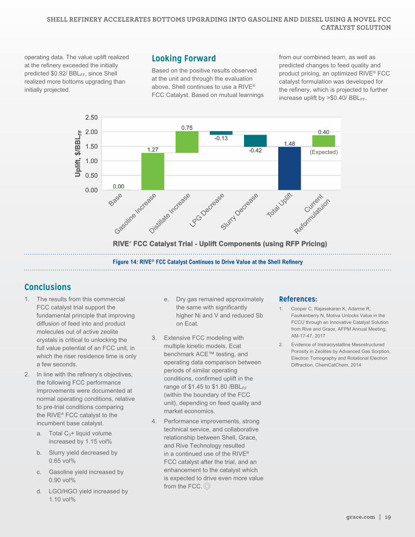
operating data. The value uplift realized at the refinery exceeded the initially predicted $0.92/ BBLFF, since Shell realized more bottoms upgrading than initially projected.
Looking ForwardBased on the positive results observed at the unit and through the evaluation above, Shell continues to use a RIVE® FCC Catalyst. Based on mutual learnings
from our combined team, as well as predicted changes to feed quality and product pricing, an optimized RIVE® FCC catalyst formulation was developed for the refinery, which is projected to further increase uplift by >$0.40/ BBLFF.
Curre
nt
Refor
mula
tuion
Tota
l Upli
ft
Slurry
Dec
reas
e
LPG D
ecre
ase
Distilla
te In
crea
se
Gasoli
ne In
crea
seBas
e
®
Figure 14: RIVE® FCC Catalyst Continues to Drive Value at the Shell Refinery
Conclusions1. The results from this commercial
FCC catalyst trial support the fundamental principle that improving diffusion of feed into and product molecules out of active zeolite crystals is critical to unlocking the full value potential of an FCC unit, in which the riser residence time is only a few seconds.
2. In line with the refinery’s objectives, the following FCC performance improvements were documented at normal operating conditions, relative to pre-trial conditions comparing the RIVE® FCC catalyst to the incumbent base catalyst.
a. Total C3+ liquid volume increased by 1.15 vol%
b. Slurry yield decreased by 0.65 vol%
c. Gasoline yield increased by 0.90 vol%
d. LGO/HGO yield increased by 1.10 vol%
e. Dry gas remained approximately the same with significantly higher Ni and V and reduced Sb on Ecat.
3. Extensive FCC modeling with multiple kinetic models, Ecat benchmark ACE™ testing, and operating data comparison between periods of similar operating conditions, confirmed uplift in the range of $1.45 to $1.80 /BBLFF (within the boundary of the FCC unit), depending on feed quality and market economics.
4. Performance improvements, strong technical service, and collaborative relationship between Shell, Grace, and Rive Technology resulted in a continued use of the RIVE® FCC catalyst after the trial, and an enhancement to the catalyst which is expected to drive even more value from the FCC.
References:1. Cooper C, Rajasekaran K, Adarme R,
Faulkenberry N, Motiva Unlocks Value in the
FCCU through an Innovative Catalyst Solution
from Rive and Grace, AFPM Annual Meeting,
AM-17-47, 2017
2. Evidence of Instracrystalline Mesostructured
Porosity in Zeolites by Advanced Gas Sorption,
Electron Tomography and Rotational Electron
Diffraction, ChemCatChem, 2014
SHELL REFINERY ACCELERATES BOTTOMS UPGRADING INTO GASOLINE AND DIESEL USING A NOVEL FCC CATALYST SOLUTION
Shepherding Hydrocracking Profitability: A New ApproachBi-Zeng Zhan Hydrocracking R&D Manager, Advanced Refining Technologies LLC (ART)
Ling Jiao Research Engineer, Advanced Refining Technologies LLC (ART)
Hyunuk Ryu Technical Services Manager, Advanced Refining Technologies LLC (ART)
Woody Shiflett Unit Manager, Applied Technology Chevron Lummus Global, USA
Theo Maesen Director, R&D Chevron Lummus Global, USA
Hydrocracking in Historic Perspectives
Hydrocracking is a flexible and resilient hydrocarbon conversion
process whose roots trace back to the conversion of coal into liquid
transportation fuels in the early part of the last century. An early
commercial scale unit to hydroprocess brown coal began operation in
ca. 1927 at Leuna (Germany). In the late 1920’s I. G. Farben (Germany)
and Standard Oil of New Jersey (USA) collaborated on hydroprocessing
heavy petroleum, but high operating pressures (1500 – 4500 psi)
and temperatures (>700 F) posed economic limits to deployments [1].
Hydrocracking had strategic implications and applications during
the Second World War, but ultimately languished in implementation
in the early post-war era. By the late 1950’s, several dynamics fed a
practical resurgence of hydrocracking [2]. The booming growth of a
motorized world provided a profound demand for increasing amounts
of gasoline, and high-performance cars demanded high-octane
gasoline. Fluidized catalytic crackers were stretched to maximize
gasoline yield, with concurrent production of low-value light cycle oil.
In addition, growth of diesel locomotive use to replace steam and the
emergence of wide-spread jet aviation added demand for diesel and
jet fuel. Significant advances in catalysis ensured the hydrocracking
process to be a key part of the solution [3].
grace.com | 21
In 1959, the California Research Corporation introduced a new hydrocracking process that was commercialized in the Standard Oil Company of California refinery in Richmond (California) [4,5]. By 1961, Universal Oil Products (now UOP) and California Research Company combined technologies to license the Isomax process, and Union Oil Company (later Unocal) announced the Unicracking process. Hydrocracking, as a viable and economic process, was off and running. Recycle hydrocracker configurations were deployed for maximum conversion. Hydrocrackers recycling unconverted oil from a fractionator at the tail-end of the reactors (single-stage recycle configuration) favored distillate production. Hydrocrackers recycling oil from a fractionator in-between the first and second reactor (two-stage recycle configuration) favored naphtha (destined for gasoline) production [6].
The licensor and technology provider landscape continued to evolve. Some heritage companies have disappeared or were part of acquisitions or mergers; new ones have emerged over time. The California Research Company and Standard Oil of California are now part of the greater Chevron corporation, and the process and catalyst technologies have been expanded and leveraged in joint ventures: Chevron Lummus Global (CLG) with McDermott and Advanced Refining Technologies (ART) with Grace.
Over the last few decades hydrocracking progress has been fueled in a few fundamental focus areas:
• The development of flexible and robust hydroprocessing catalysts based upon tailored materials comprising mesoporous amorphous silica-aluminas, nanoporous crystalline silica-aluminas, and tailored mixed metal sulfide nanostructures [3,7,8]
• Tailoring catalyst systems to processing needs through parallel testing coupled with modeling capabilities [9]
• Advances in analytical chemistry focused on understanding fractions that are recalcitrant to hydroprocessing, shorten run length and can cause operational problems (causing “red death” through sedimentation in equipment)
The focus of this current contribution is on managing these recalcitrant fractions. Optimization of both operations and catalyst utilization must rely on this foundation. Impressive work was conducted early on in characterizing aromatic molecules by HPLC, UV spectroscopy and mass spectrometry with notable efforts at Arco and Chevron [10, 11]. The development of a Polycyclic Index, or PCI parameter at Chevron in the early 1970’s greatly enabled prediction of catalyst performance and helped establish design guidelines for recalcitrant feedstocks. However, analytical technologies were limited in their ability to specifically identify and quantify defined fractions to operational decline and catalyst fouling. Recent advances particularly in high-resolution mass spectrometry techniques have now bridged that gap [2, 12, 13, 14].
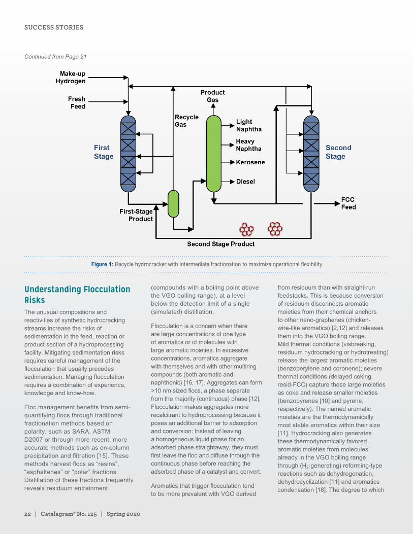
Both operability and maximization of catalyst cycles depend on mitigating the detrimental effects of recalcitrant aromatics, either through design considerations or improved catalyst systems. Particularly in a two-stage recycle configuration (Figure 1), the low temperature operation of a noble metal second stage catalyst can mitigate recalcitrant aromatics buildup, but the low second stage temperature required for managing recalcitrant fractions limits hydrocracking conversion [8]. Inclusion of a deep hydrogenation catalyst from the ICR® 1000 catalyst family at the appropriate location offers a more robust and flexible means to address these challenges [14].
Recycle Hydrocracking for Maximum Flexibility Even though two-stage recycle configurations were originally designed to maximize naphtha production and volume swell, they became preferred over single-stage recycle configurations when flexibility in both feedstocks and product slates was desired [1, 8]. Fractionation after the first reactor removes intermediate products and waste streams (fuels, H2S, NH3) before deeply hydrocracking in the second reactor.
Irrespective of the configuration, the key objective of the first hydrocracking reactor is to severely reduce the compounds that inhibit hydrocracking, such as metals, sulfur, nitrogen and aromatic compounds. Excellent heat management by proper internals, a high hydrogen partial pressure, and a well-designed catalyst system with gradually increasing hydrogenation activity contribute to optimum first stage operation.
The second reactor hydrocracks both feed from the first reactor and unconverted oil recycled from the fractionator. Since the fractionator removes the converted oil as product, it concentrates the most recalcitrant components in the recycle stream. It is important to assure compatibility of the unconverted streams from the first and from the second reactors. This is particularly important when hydrocracking so-called “synthetic” vacuum gas oil (VGO), i.e. a feedstock made with components that have already been processed.
Continued on Page 22
SHEPHERDING HYDROCRACKING PROFITABILITY: A NEW APPROACH
22 | Catalagram® No. 125 | Spring 2020
Figure 1: Recycle hydrocracker with intermediate fractionation to maximize operational flexibility
Understanding Flocculation RisksThe unusual compositions and reactivities of synthetic hydrocracking streams increase the risks of sedimentation in the feed, reaction or product section of a hydroprocessing facility. Mitigating sedimentation risks requires careful management of the flocculation that usually precedes sedimentation. Managing flocculation requires a combination of experience, knowledge and know-how.
Floc management benefits from semi-quantifying flocs through traditional fractionation methods based on polarity, such as SARA, ASTM D2007 or through more recent, more accurate methods such as on-column precipitation and filtration [15]. These methods harvest flocs as “resins”, “asphaltenes” or “polar” fractions. Distillation of these fractions frequently reveals residuum entrainment
(compounds with a boiling point above the VGO boiling range), at a level below the detection limit of a single (simulated) distillation.
Flocculation is a concern when there are large concentrations of one type of aromatics or of molecules with large aromatic moieties. In excessive concentrations, aromatics aggregate with themselves and with other multiring compounds (both aromatic and naphthenic) [16, 17]. Aggregates can form >10 nm sized flocs, a phase separate from the majority (continuous) phase [12]. Flocculation makes aggregates more recalcitrant to hydroprocessing because it poses an additional barrier to adsorption and conversion: Instead of leaving a homogeneous liquid phase for an adsorbed phase straightaway, they must first leave the floc and diffuse through the continuous phase before reaching the adsorbed phase of a catalyst and convert.
Aromatics that trigger flocculation tend to be more prevalent with VGO derived
from residuum than with straight-run feedstocks. This is because conversion of residuum disconnects aromatic moieties from their chemical anchors to other nano-graphenes (chicken-wire-like aromatics) [2,12] and releases them into the VGO boiling range. Mild thermal conditions (visbreaking, residuum hydrocracking or hydrotreating) release the largest aromatic moieties (benzoperylene and coronene); severe thermal conditions (delayed coking, resid-FCC) capture these large moieties as coke and release smaller moieties (benzopyrenes [10] and pyrene, respectively). The named aromatic moieties are the thermodynamically most stable aromatics within their size [11]. Hydrocracking also generates these thermodynamically favored aromatic moieties from molecules already in the VGO boiling range through (H2-generating) reforming-type reactions such as dehydrogenation, dehydrocyclization [11] and aromatics condensation [18]. The degree to which
Continued from Page 21
SUCCESS STORIES
grace.com | 23
aggregating and flocculating aromatics stem from the residuum or from the VGO boiling range depends on the specific synthetic feed and conditions.
Synthetic feedstocks can also introduce other unusually recalcitrant compounds, e.g. a polyamide chain sedimented after prolonged storage inside a hydroprocessed product, suggesting that it survived as an aggregate or a floc while the continuous phase was severely hydrogenated and partially hydrocracked. Hydrotreating of hydrocracked Canadian bitumen retains recalcitrant nitrogen compounds with a core described by C15H13N [19,20], and identified as mostly 4,8,9,10-tetrahydrocyclohepta[def]carbazole [21]. Why this novel compound would be so unusually recalcitrant requires further investigation [13].
Principles of Floc Management Many approaches have been evaluated to manage the concentration of aromatics that are prone to flocculation to prevent sedimentation in reactor or product sections. Conventionally a (financially) significant fraction of the recycle stream is bled from the hydrocracker (Figure 1).
To stem the bleed stream without incurring sedimentation, physical separations have been evaluated. Examples are sedimentation through cooling of the recycle stream [22] or through addition of a flocculant [23] followed by periodically siphoning off the sediment, adsorption of the aromatics prone to sedimentation [24], and distillation to remove the heaviest boiling fraction where the recalcitrant molecules reside [25]. Even though adsorption and distillation have remained in commercial practice for many decades, it is safe to say that they have not become main stream. This suggests that the physical separation methods have technical merit but not a highly convincing economic benefit.
Catalytic options to mitigate the bleeding without prior separation of flocs became available recently with the deployment
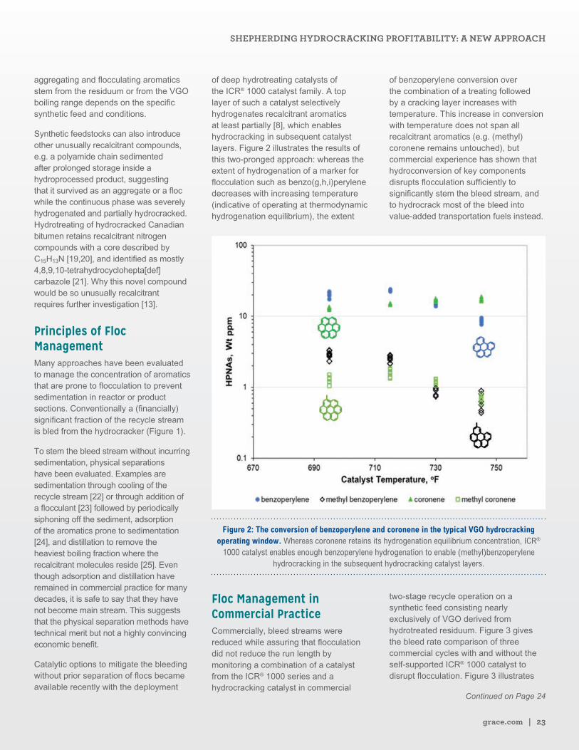
of deep hydrotreating catalysts of the ICR® 1000 catalyst family. A top layer of such a catalyst selectively hydrogenates recalcitrant aromatics at least partially [8], which enables hydrocracking in subsequent catalyst layers. Figure 2 illustrates the results of this two-pronged approach: whereas the extent of hydrogenation of a marker for flocculation such as benzo(g,h,i)perylene decreases with increasing temperature (indicative of operating at thermodynamic hydrogenation equilibrium), the extent
of benzoperylene conversion over the combination of a treating followed by a cracking layer increases with temperature. This increase in conversion with temperature does not span all recalcitrant aromatics (e.g. (methyl)coronene remains untouched), but commercial experience has shown that hydroconversion of key components disrupts flocculation sufficiently to significantly stem the bleed stream, and to hydrocrack most of the bleed into value-added transportation fuels instead.
Figure 2: The conversion of benzoperylene and coronene in the typical VGO hydrocracking operating window. Whereas coronene retains its hydrogenation equilibrium concentration, ICR®
1000 catalyst enables enough benzoperylene hydrogenation to enable (methyl)benzoperylene hydrocracking in the subsequent hydrocracking catalyst layers.
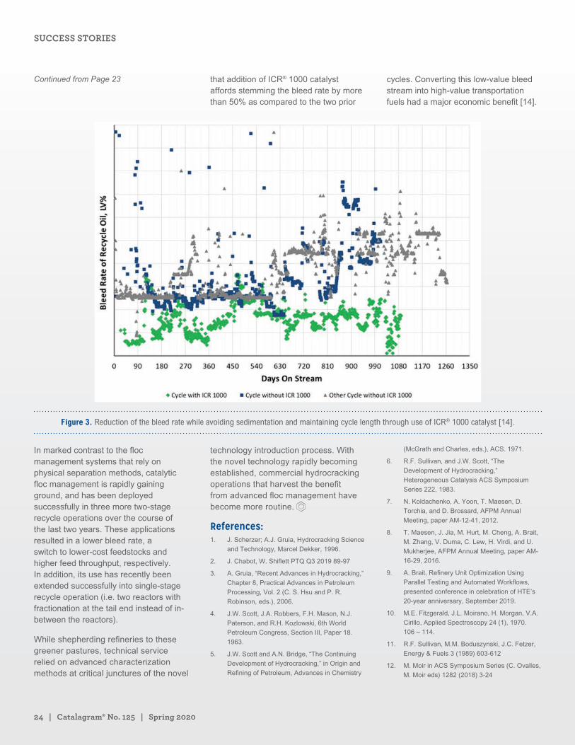
Floc Management in Commercial PracticeCommercially, bleed streams were reduced while assuring that flocculation did not reduce the run length by monitoring a combination of a catalyst from the ICR® 1000 series and a hydrocracking catalyst in commercial
two-stage recycle operation on a synthetic feed consisting nearly exclusively of VGO derived from hydrotreated residuum. Figure 3 gives the bleed rate comparison of three commercial cycles with and without the self-supported ICR® 1000 catalyst to disrupt flocculation. Figure 3 illustrates
Continued on Page 24
SHEPHERDING HYDROCRACKING PROFITABILITY: A NEW APPROACH
24 | Catalagram® No. 125 | Spring 2020
that addition of ICR® 1000 catalyst affords stemming the bleed rate by more than 50% as compared to the two prior
cycles. Converting this low-value bleed stream into high-value transportation fuels had a major economic benefit [14].
Figure 3. Reduction of the bleed rate while avoiding sedimentation and maintaining cycle length through use of ICR® 1000 catalyst [14].
In marked contrast to the floc management systems that rely on physical separation methods, catalytic floc management is rapidly gaining ground, and has been deployed successfully in three more two-stage recycle operations over the course of the last two years. These applications resulted in a lower bleed rate, a switch to lower-cost feedstocks and higher feed throughput, respectively. In addition, its use has recently been extended successfully into single-stage recycle operation (i.e. two reactors with fractionation at the tail end instead of in-between the reactors).
While shepherding refineries to these greener pastures, technical service relied on advanced characterization methods at critical junctures of the novel
technology introduction process. With the novel technology rapidly becoming established, commercial hydrocracking operations that harvest the benefit from advanced floc management have become more routine.
References:1. J. Scherzer; A.J. Gruia, Hydrocracking Science
and Technology, Marcel Dekker, 1996.
2. J. Chabot, W. Shiflett PTQ Q3 2019 89-97
3. A. Gruia, “Recent Advances in Hydrocracking,”
Chapter 8, Practical Advances in Petroleum
Processing, Vol. 2 (C. S. Hsu and P. R.
Robinson, eds.), 2006.
4. J.W. Scott, J.A. Robbers, F.H. Mason, N.J.
Paterson, and R.H. Kozlowski, 6th World
Petroleum Congress, Section III, Paper 18.
1963.
5. J.W. Scott and A.N. Bridge, “The Continuing
Development of Hydrocracking,” in Origin and
Refining of Petroleum, Advances in Chemistry
(McGrath and Charles, eds.), ACS. 1971.
6. R.F. Sullivan, and J.W. Scott, “The
Development of Hydrocracking,”
Heterogeneous Catalysis ACS Symposium
Series 222, 1983.
7. N. Koldachenko, A. Yoon, T. Maesen, D.
Torchia, and D. Brossard, AFPM Annual
Meeting, paper AM-12-41, 2012.
8. T. Maesen, J. Jia, M. Hurt, M. Cheng, A. Brait,
M. Zhang, V. Duma, C. Lew, H. Virdi, and U.
Mukherjee, AFPM Annual Meeting, paper AM-
16-29, 2016.
9. A. Brait, Refinery Unit Optimization Using
Parallel Testing and Automated Workflows,
presented conference in celebration of HTE’s
20-year anniversary, September 2019.
10. M.E. Fitzgerald, J.L. Moirano, H. Morgan, V.A.
Cirillo, Applied Spectroscopy 24 (1), 1970.
106 – 114.
11. R.F. Sullivan, M.M. Boduszynski, J.C. Fetzer,
Energy & Fuels 3 (1989) 603-612
12. M. Moir in ACS Symposium Series (C. Ovalles,
M. Moir eds) 1282 (2018) 3-24
Continued from Page 23
SUCCESS STORIES
grace.com | 25
13. C. Ovalles, E. Rogel, M. Hurt, V. Duma,
H. Morazan, K. Hench, M. Moir in ACS
Symposium Series 1320 (2019) 261-280.
14. D. Blackwell, T. Maesen, V. Duma, H. Ryu,
Catalagram 122 (2018) 12-17.
15. E. Rogel, C. Ovalles, M. Moir, US 9,671,384
16. L. von Boente, Brennstoff Chemie, 36 (1955)
210-214.
17. T. Janowski, P. Pulay, J.Am.Chem.Soc. 134
(2012) 17520-17525.
18. J.C. Fetzer, Polycyclic Aromatic Compounds 4
(1994) 19-24.
19. W. Kanda, I. Siu, J. Adjaye, A.E. Nelson,
M.R.Gray, Energy & Fuels 18 (2004) 539-546.
20. J. Fu, G.C. Klein, D.F. Smith, S. Kim, R.P.
Rodgers, C.L. Hendrickson,A.G. Marshall
Energy & Fuels 20 (2006) 1235-1241.
21. P. Wiwel, B. Hinnemann, A. Hidalgo-Vivas, P.
Zeuthen, B.O. Petersen, and J.Ø. Duus, Ind.
Eng. Chem. Res. 49 (2010) 3184–3193.
22. 22) G.W. Hendricks, E.C. Attane, J.W.
Wilson, US 3619407
23. J.C. Fetzer, J.M. Rosenbaum, R.W. Bachtel,
D.R. Cash, D.G. Lammel, US 5323577
24. P.R. Lamb, S.T. Bakas, B.M. Wood, US
4447315
25. V. Ramaseshan, A.A. Al-Turki, A. A. Al-Hajji,
F. Adam, A.S. Al-Ghamdi, Hydrocarbon
Processing 95(6) (2016) 49-52.
Follow Us for A Better Perspective on Hydroprocessing
Follow us for more ART Hydroprocessing™ catalyst solutions and keep up with the latest news, information, and innovations from Advanced Refining Technologies LLC.
arthydroprocessing.com
linkedin.com/company/ arthydroprocessing/
@ARTCatalysts
SHEPHERDING HYDROCRACKING PROFITABILITY: A NEW APPROACH
A Customer-Driven Innovation StoryLeonardo Betancourt Technical Service Manager W. R. Grace & Co.
Bob Riley Regional Marketing Manager, Americas W. R. Grace & Co.
Milton J. Chávez Urdánigo FCC Process Engineer EP PetroEcuador
Eduardo Estrada Technical Service Manager, Latin America W. R. Grace & Co.
Every company in the refining industry seeks to
maximize profits. Often, when a refinery needs to
increase profit, they turn their attention to the Fluid
Catalytic Cracking (FCC) Unit. Its ability to process a wide
range of feeds from different process units and convert
those into valuable products makes the FCC one of the
most important process units in the refinery.
To drive value for refineries, Grace continually develops
new FCC solutions driven by customer needs – what
we call Customer Driven Innovation. Grace works
closely with refiners to determine their need and
provide outstanding products supported by industry-
leading technical services.
As part of the Customer Driven Innovation process,
Grace visited Esmeraldas Refinery of PetroEcuador
to meet with the Operations and Process Engineering
departments in anticipation of a request for proposal
(RFP) for a catalyst solution to meet their FCC unit
objectives of increasing LPG and gasoline yields.
grace.com | 27
After collecting information, Grace designed a unique catalyst solution specifically for PetroEcuador. The first consideration in this design was feed characterization, which determined the type of hydrocarbons that need to be cracked in the reactor. The feed characterization determined the maximum LPG and gasoline that can be obtained from that feed based on its makeup.
Next the team examined Ecat properties from the current operations, to set a baseline for the catalyst properties that needed to be improved with the new Grace catalyst solution. Grace reviewed all the process conditions, yields, and limitations of their FCC in detail, to set boundaries for the impact of the new catalyst on the process.
With this analysis in hand, Grace was able to develop a range of new catalyst solutions to fit the PetroEcuador FCC. To identify the best option, lab tests were carried out, which included an ACE™ study to compare the performance of the different catalyst solutions. An ACE™ study involves both a catalyst deactivation step (via an internal deactivation protocol at a metals level similar to the Ecat), and testing of the refinery’s feedstock. All catalyst solutions were tested under same conditions and set of catalyst-to-oil ratios to develop curves of yields selectivity at different reactor temperatures.
The FCC unit operates in a heat balanced fashion, and the conditions to achieve heat balance are subject to the operational requirements and constraints for the FCC. A very important variable in heat balance is the delta coke (the amount of coke produced on the catalyst in one cycle through the reactor), which affects the operational conditions and, therefore, the product yield.
Delta coke is highly dependent on the catalyst. Thus, it is very important to evaluate the effect of the catalyst in the heat balance to get an accurate picture of catalyst performance in the unit. Keeping this in mind, the FCC unit of the Esmeraldas Refinery was simulated using a Grace prediction
model and all the information gathered from the refinery related to operational conditions, equipment limitations, feed, Ecat properties, and product qualities. In every catalyst selection process, it is very important to have reliable and accurate operational data information from the unit, because this is what defines the success of any prediction-modelling effort.
The results from the ACE™ testing were used into the model to simulate each catalyst solution and compare different operational scenarios between them. This allowed Grace to study the unit yields, determine optimal operational conditions, yields, and limitations, and then to fine tune any the catalyst properties necessary to select the best catalyst solution that will bring the most value for the refinery.
One of the most important conditions for this particular FCC unit was that the reactor was running -10°C below typical operation conditions at the time of the RFP. After discussing this with the refinery, Grace realized that the pressure drop of the regenerated catalyst slide valve was at minimum and very close to the safety shutdown limit. If this limit was exceeded, a reverse flow scenario could compromise the integrity of the unit.
With this knowledge, Grace determined that the unit was limited by catalyst circulation rate (CCR), primarily due to a low regenerator temperature that created a need for higher CCR to meet the heat requirements in the reactor. To overcome this limitation, the new catalyst must deliver higher activity to promote cracking and produce a higher level of catalytic coke. This higher level of coke would be burned in the regenerator to increase the dense bed temperatures and relieve the lower CCR and low pressure drop of the slide valve. This would give a better operational window for the refinery to operate at higher reactor temperatures and increase conversion if needed.
Following our customer-driven process of information gathering, assessment, and testing, Grace was able to address this, and other operational conditions, to get a complete understanding of the needs of
this refinery to consider in the selection process for a new catalyst solution.
To create an effective communication channel and follow up on the catalyst change in the unit, Grace and the refinery developed work processes that involved meetings, conference calls, lab, and operational data analysis. Ecat, feed, gasoline, LCO, HCO, and slurry characterizations were done in Grace laboratories as part of the technical support promised to the refinery. These analyses were used to confirm and supplement the refiner’s laboratory testing.
SuccessAs soon as the catalyst hit the unit, the refinery and Grace began conducting regular conference calls with the refinery to discuss any important changes in the unit, such as process variables, Ecat properties, and product yields. During the catalyst change the refinery sent Grace multiple Ecat samples per week to track each change of the properties to make sure the changes were progressing into the right direction.
The regular conference calls were accompanied by regular site visits to review all the process conditions in detail. These included the catalyst change progress, analysis of the Ecat properties where the improvements were notable, analysis of the main operational variables, and an evaluation of opportunities to improve operations and yields, getting the best performance from the catalyst.
The conference calls and visits provided an important mechanism to improve operational conditions. During the catalyst change out, it was revealed that even when the lift zone velocity was in the typical range, the unit had room for further yield improvements. Operating the riser with low velocity in the lift zone results in back-mixing of the catalyst, and sub-optimal contact of feed to catalyst active sites (poor mass transfer). The refinery adjusted the lift
Continued on Page 28
A CUSTOMER-DRIVEN INNOVATION STORY
28 | Catalagram® No. 125 | Spring 2020
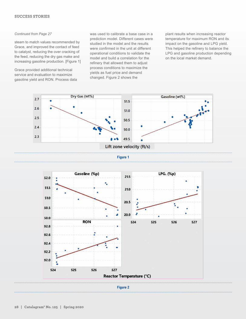
steam to match values recommended by Grace, and improved the contact of feed to catalyst, reducing the over cracking of the feed, reducing the dry gas make and increasing gasoline production. [Figure 1]
Grace provided additional technical service and evaluation to maximize gasoline yield and RON. Process data
was used to calibrate a base case in a prediction model. Different cases were studied in the model and the results were confirmed in the unit at different operational conditions to validate the model and build a correlation for the refinery that allowed them to adjust process conditions to maximize the yields as fuel price and demand changed. Figure 2 shows the
plant results when increasing reactor temperature for maximum RON and its impact on the gasoline and LPG yield. This helped the refinery to balance the LPG and gasoline production depending on the local market demand.
Figure 1
Figure 2
Continued from Page 27
SUCCESS STORIES
grace.com | 29
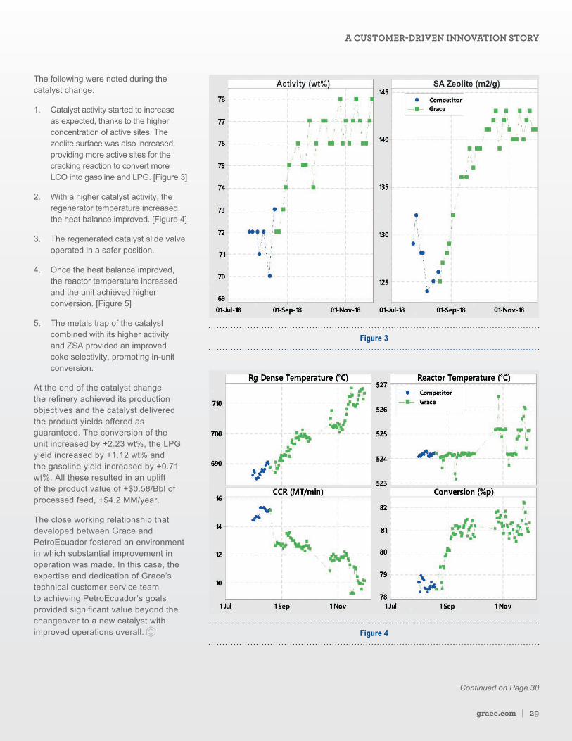
The following were noted during the catalyst change:
1. Catalyst activity started to increase as expected, thanks to the higher concentration of active sites. The zeolite surface was also increased, providing more active sites for the cracking reaction to convert more LCO into gasoline and LPG. [Figure 3]
2. With a higher catalyst activity, the regenerator temperature increased, the heat balance improved. [Figure 4]
3. The regenerated catalyst slide valve operated in a safer position.
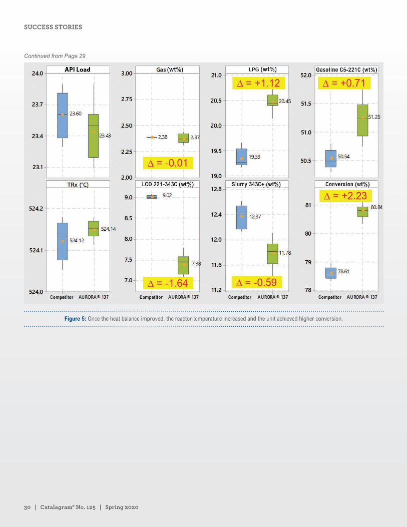
4. Once the heat balance improved, the reactor temperature increased and the unit achieved higher conversion. [Figure 5]
5. The metals trap of the catalyst combined with its higher activity and ZSA provided an improved coke selectivity, promoting in-unit conversion.
At the end of the catalyst change the refinery achieved its production objectives and the catalyst delivered the product yields offered as guaranteed. The conversion of the unit increased by +2.23 wt%, the LPG yield increased by +1.12 wt% and the gasoline yield increased by +0.71 wt%. All these resulted in an uplift of the product value of +$0.58/Bbl of processed feed, +$4.2 MM/year.
The close working relationship that developed between Grace and PetroEcuador fostered an environment in which substantial improvement in operation was made. In this case, the expertise and dedication of Grace’s technical customer service team to achieving PetroEcuador’s goals provided significant value beyond the changeover to a new catalyst with improved operations overall.
Figure 3
Figure 4
Continued on Page 30
A CUSTOMER-DRIVEN INNOVATION STORY
30 | Catalagram® No. 125 | Spring 2020
Figure 5: Once the heat balance improved, the reactor temperature increased and the unit achieved higher conversion.
Continued from Page 29
SUCCESS STORIES
Distillate Pool Maximization by Exploiting the Use of Opportunity Feedstocks such as LCO and Synthetic StocksBen Koenigsknecht Marketing Manager Advanced Refining Technologies LLC (ART)
Charles Olsen Global Technology Manager, DHT Advanced Refining Technologies LLC (ART)
Brian Watkins Senior Manager, Technical Service Advanced Refining Technologies LLC (ART)
“Everything old is new again.” When the article
below was written in 2009, ULSD demand had
pushed the previous year’s distillate crack spreads
to 10-year highs for much of the world, and refiners
were looking for ways to maximize their diesel pool
to take advantage of these market conditions. Flash
forward 11 years, and in many markets distillate
crack spreads are forecast to hit levels not seen
since 2008 due to market dynamics caused by the
start of the IMO 2020 bunker fuel specifications
(Wood Mackenzie, 2020).
Since the publication of the article, catalyst
technology has continued to improve, making the
processing of challenging feedstocks even more
attractive. Combined with the return of improved
distillate cracks, the article is as timely as ever.
This article was originally published in Catalagram 105 in Spring 2009.
Continued on Page 32
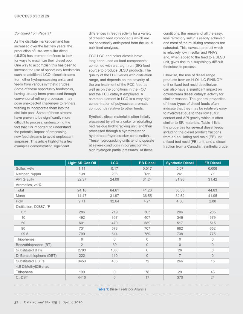
32 | Catalagram® No. 125 | Spring 2020
As the distillate market demand has increased over the last few years, the production of ultra-low sulfur diesel (ULSD) has prompted refiners to look for ways to maximize their diesel pool. One way to accomplish this has been to increase the use of opportunity feedstocks such as additional LCO, diesel streams from other hydroprocessing units, and feeds from various synthetic crudes. Some of these opportunity feedstocks, having already been processed through conventional refinery processes, may pose unexpected challenges to refiners wishing to incorporate them into the distillate pool. Some of these streams have proven to be significantly more difficult to process, underscoring the fact that it is important to understand the potential impact of processing new feed streams to avoid unpleasant surprises. This article highlights a few examples demonstrating significant
differences in feed reactivity for a variety of different feed components which are not necessarily anticipated from the usual bulk feed analyses.
FCC LCO and coker diesels have long been used as feed components combined with a straight run (SR) feed source to produce ULSD products. The quality of the LCO varies with distillation range, and depends on the severity of the pre-treatment of the FCC feed as well as on the conditions in the FCC and the FCC catalyst employed. A common element in LCO is a very high concentration of polynuclear aromatic compounds relative to other feeds.
Synthetic diesel material is often initially processed by either a coker or ebullating bed residue hydrocracking unit, and then processed through a hydrotreater or hydrotreater/hydrocracker combination. These hydrocracking units tend to operate at severe conditions in conjunction with high hydrogen partial pressures. At these
conditions, the removal of all the easy, less refractory sulfur is readily achieved, and most of the multi-ring aromatics are saturated. This leaves a product which is relatively low in sulfur and PNA’s and, when added to the feed to a ULSD unit, gives rise to a surprisingly difficult feedstock to process.
Likewise, the use of diesel range products from an H-Oil, LC-FINING™ unit or fixed bed resid desulfurizer can also have a significant impact on downstream diesel catalyst activity for similar reasons. The general properties of these types of diesel feeds often indicate that they may be relatively easy to hydrotreat due to their low sulfur content and API gravity which is often similar to SR materials. Table 1 lists the properties for several diesel feeds including the diesel product fractions from an ebullating bed resid (EB) unit, a fixed bed resid (FB) unit, and a diesel fraction from a Canadian synthetic crude.
Light SR Gas Oil LCO EB Diesel Synthetic Diesel FB Diesel
Sulfur, wt% 1.11 0.17 0.017 0.07 0.006
Nitrogen, wppm 138 203 135 261 71
API Gravity 32.37 24.09 31.24 31.96 31.42
Aromatics, vol%
Total 24.18 64.61 41.26 36.58 44.83
Mono 14.47 31.97 36.55 32.52 41.95
Poly 9.71 32.64 4.71 4.06 2.88
Distillation, D2887, ˚F
0.5 286 219 303 206 285
10 492 367 407 349 379
50 601 470 589 517 515
90 731 578 707 662 652
99.5 799 644 759 738 775
Thiophenes 8 0 0 0 0
Benzothiophenes (BT) 2 69 0 0 0
Substituted BT’s 2793 1083 0 26 0
Di Benzothiophene (DBT) 222 110 0 7 0
Substituted DBT’s 3453 436 72 266 15
4,6 DiMethylDiBenzo
Thiophene 199 0 78 29 43
C3-DBT 4410 0 17 370 24
Table 1: Diesel Feedstock Analysis
Continued from Page 31
SUCCESS STORIES
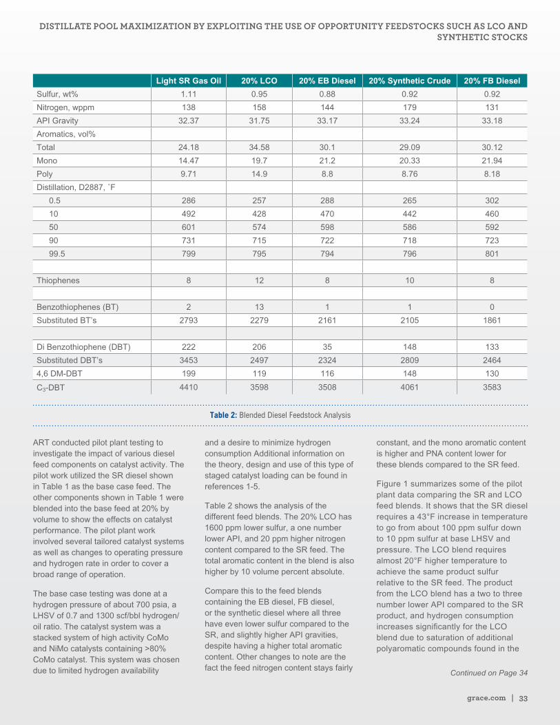
grace.com | 33
Light SR Gas Oil 20% LCO 20% EB Diesel 20% Synthetic Crude 20% FB Diesel
Sulfur, wt% 1.11 0.95 0.88 0.92 0.92
Nitrogen, wppm 138 158 144 179 131
API Gravity 32.37 31.75 33.17 33.24 33.18
Aromatics, vol%
Total 24.18 34.58 30.1 29.09 30.12
Mono 14.47 19.7 21.2 20.33 21.94
Poly 9.71 14.9 8.8 8.76 8.18
Distillation, D2887, ˚F
0.5 286 257 288 265 302
10 492 428 470 442 460
50 601 574 598 586 592
90 731 715 722 718 723
99.5 799 795 794 796 801
Thiophenes 8 12 8 10 8
Benzothiophenes (BT) 2 13 1 1 0
Substituted BT’s 2793 2279 2161 2105 1861
Di Benzothiophene (DBT) 222 206 35 148 133
Substituted DBT’s 3453 2497 2324 2809 2464
4,6 DM-DBT 199 119 116 148 130
C3-DBT 4410 3598 3508 4061 3583
Table 2: Blended Diesel Feedstock Analysis
ART conducted pilot plant testing to investigate the impact of various diesel feed components on catalyst activity. The pilot work utilized the SR diesel shown in Table 1 as the base case feed. The other components shown in Table 1 were blended into the base feed at 20% by volume to show the effects on catalyst performance. The pilot plant work involved several tailored catalyst systems as well as changes to operating pressure and hydrogen rate in order to cover a broad range of operation.
The base case testing was done at a hydrogen pressure of about 700 psia, a LHSV of 0.7 and 1300 scf/bbl hydrogen/oil ratio. The catalyst system was a stacked system of high activity CoMo and NiMo catalysts containing >80% CoMo catalyst. This system was chosen due to limited hydrogen availability
and a desire to minimize hydrogen consumption Additional information on the theory, design and use of this type of staged catalyst loading can be found in references 1-5.
Table 2 shows the analysis of the different feed blends. The 20% LCO has 1600 ppm lower sulfur, a one number lower API, and 20 ppm higher nitrogen content compared to the SR feed. The total aromatic content in the blend is also higher by 10 volume percent absolute.
Compare this to the feed blends containing the EB diesel, FB diesel, or the synthetic diesel where all three have even lower sulfur compared to the SR, and slightly higher API gravities, despite having a higher total aromatic content. Other changes to note are the fact the feed nitrogen content stays fairly
constant, and the mono aromatic content is higher and PNA content lower for these blends compared to the SR feed.
Figure 1 summarizes some of the pilot plant data comparing the SR and LCO feed blends. It shows that the SR diesel requires a 43°F increase in temperature to go from about 100 ppm sulfur down to 10 ppm sulfur at base LHSV and pressure. The LCO blend requires almost 20°F higher temperature to achieve the same product sulfur relative to the SR feed. The product from the LCO blend has a two to three number lower API compared to the SR product, and hydrogen consumption increases significantly for the LCO blend due to saturation of additional polyaromatic compounds found in the
Continued on Page 34
DISTILLATE POOL MAXIMIZATION BY EXPLOITING THE USE OF OPPORTUNITY FEEDSTOCKS SUCH AS LCO AND SYNTHETIC STOCKS
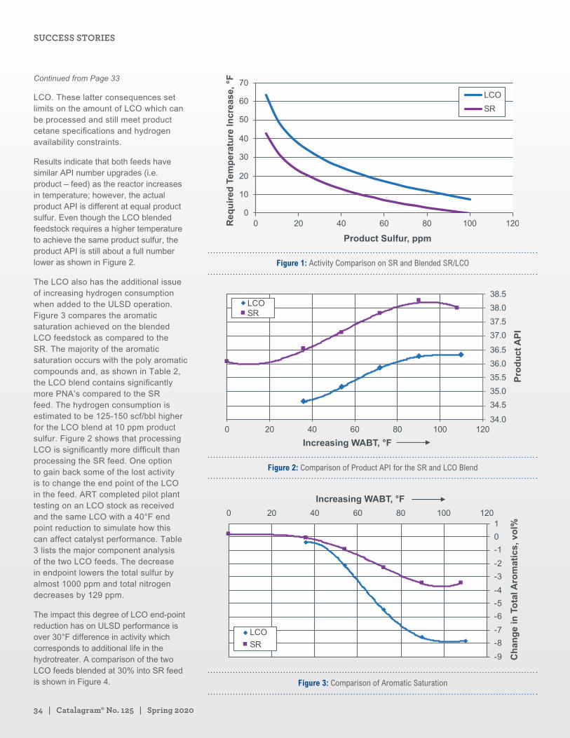
34 | Catalagram® No. 125 | Spring 2020
LCO. These latter consequences set limits on the amount of LCO which can be processed and still meet product cetane specifications and hydrogen availability constraints.
Results indicate that both feeds have similar API number upgrades (i.e. product – feed) as the reactor increases in temperature; however, the actual product API is different at equal product sulfur. Even though the LCO blended feedstock requires a higher temperature to achieve the same product sulfur, the product API is still about a full number lower as shown in Figure 2.
The LCO also has the additional issue of increasing hydrogen consumption when added to the ULSD operation. Figure 3 compares the aromatic saturation achieved on the blended LCO feedstock as compared to the SR. The majority of the aromatic saturation occurs with the poly aromatic compounds and, as shown in Table 2, the LCO blend contains significantly more PNA’s compared to the SR feed. The hydrogen consumption is estimated to be 125-150 scf/bbl higher for the LCO blend at 10 ppm product sulfur. Figure 2 shows that processing LCO is significantly more difficult than processing the SR feed. One option to gain back some of the lost activity is to change the end point of the LCO in the feed. ART completed pilot plant testing on an LCO stock as received and the same LCO with a 40°F end point reduction to simulate how this can affect catalyst performance. Table 3 lists the major component analysis of the two LCO feeds. The decrease in endpoint lowers the total sulfur by almost 1000 ppm and total nitrogen decreases by 129 ppm.
The impact this degree of LCO end-point reduction has on ULSD performance is over 30°F difference in activity which corresponds to additional life in the hydrotreater. A comparison of the two LCO feeds blended at 30% into SR feed is shown in Figure 4.
Figure 1: Activity Comparison on SR and Blended SR/LCO
Figure 2: Comparison of Product API for the SR and LCO Blend
Figure 3: Comparison of Aromatic Saturation
Continued from Page 33
SUCCESS STORIES
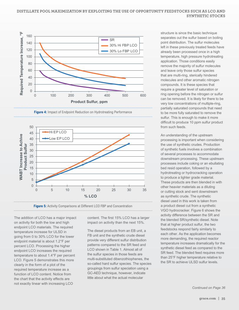
grace.com | 35
Figure 4: Impact of Endpoint Reduction on Hydrotreating Performance
Figure 5: Activity Comparisons at Different LCO FBP and Concentration
The addition of LCO has a major impact on activity for both the low and high endpoint LCO materials. The required temperature increase for ULSD in going from 0 to 30% LCO for the lower endpoint material is about 1.2°F per percent LCO. Processing the higher endpoint LCO increases the required temperature to about 1.4°F per percent LCO. Figure 5 demonstrates this more clearly in the form of a plot of the required temperature increase as a function of LCO content. Notice from the chart that the activity effects are not exactly linear with increasing LCO
content. The first 15% LCO has a larger impact on activity than the next 15%.
The diesel products from an EB unit, a FB unit and the synthetic crude diesel provide very different sulfur distribution patterns compared to the SR feed and LCO shown in Table 1. Almost all of the sulfur species in those feeds are multi-substituted dibenzothiophenes, the so-called hard sulfur species. The species groupings from sulfur speciation using a GC-AED technique, however, indicate little about what the actual molecular
structure is since the basic technique separates out the sulfur based on boiling point distribution. The sulfur molecules left in these previously treated feeds have already been processed once in a high temperature, high pressure hydrotreating application. Those conditions easily remove the majority of sulfur molecules and leave only those sulfur species that are multi-ring, sterically hindered molecules and other aromatic nitrogen compounds. It is these species that require a greater level of saturation or ring opening before the nitrogen or sulfur can be removed. It is likely for there to be very low concentrations of multiple-ring, partially saturated compounds that need to be more fully saturated to remove the sulfur. This is enough to make it more difficult to produce 10 ppm sulfur product from such feeds.
An understanding of the upstream processing is important when considering the use of synthetic crudes. Production of synthetic fuels involves a combination of several processes to accommodate downstream processing. These upstream processes include coking or an ebullating bed resid operation, followed by a hydrotreating or hydrocracking operation to produce a lighter grade material. These products are then blended in with other heavier materials as a diluting or cutting stock and sent downstream as synthetic crude. The synthetic diesel used in this work is taken from a product diesel cut from a synthetic VGO hydrocracker. Figure 6 shows the activity difference between the SR and the blended SR/synthetic diesel. Note that at higher product sulfur, the two feedstocks respond fairly similarly to each other. As the application becomes more demanding, the required reactor temperature increases dramatically for the synthetic diesel feed as compared to the SR feed. The blended feed requires more than 25°F higher temperature relative to the SR to achieve ULSD sulfur levels.
Continued on Page 36
DISTILLATE POOL MAXIMIZATION BY EXPLOITING THE USE OF OPPORTUNITY FEEDSTOCKS SUCH AS LCO AND SYNTHETIC STOCKS
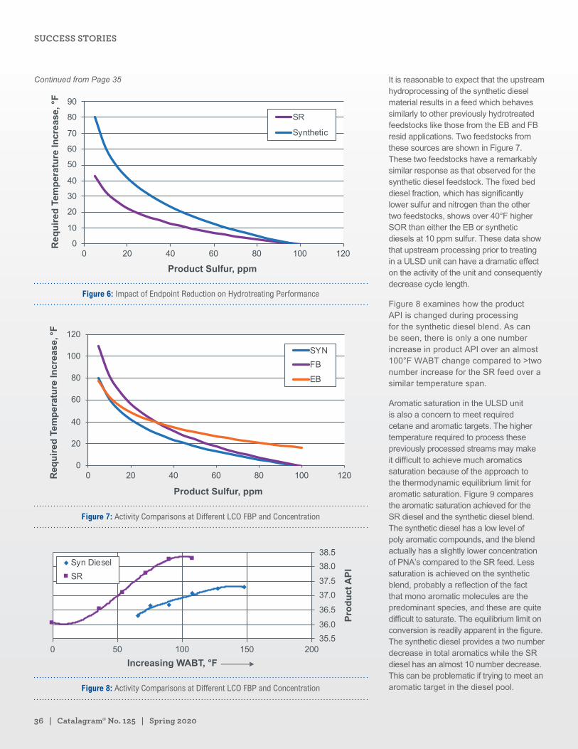
36 | Catalagram® No. 125 | Spring 2020
Figure 6: Impact of Endpoint Reduction on Hydrotreating Performance
Figure 7: Activity Comparisons at Different LCO FBP and Concentration
Figure 8: Activity Comparisons at Different LCO FBP and Concentration
It is reasonable to expect that the upstream hydroprocessing of the synthetic diesel material results in a feed which behaves similarly to other previously hydrotreated feedstocks like those from the EB and FB resid applications. Two feedstocks from these sources are shown in Figure 7. These two feedstocks have a remarkably similar response as that observed for the synthetic diesel feedstock. The fixed bed diesel fraction, which has significantly lower sulfur and nitrogen than the other two feedstocks, shows over 40°F higher SOR than either the EB or synthetic diesels at 10 ppm sulfur. These data show that upstream processing prior to treating in a ULSD unit can have a dramatic effect on the activity of the unit and consequently decrease cycle length.
Figure 8 examines how the product API is changed during processing for the synthetic diesel blend. As can be seen, there is only a one number increase in product API over an almost 100°F WABT change compared to >two number increase for the SR feed over a similar temperature span.
Aromatic saturation in the ULSD unit is also a concern to meet required cetane and aromatic targets. The higher temperature required to process these previously processed streams may make it difficult to achieve much aromatics saturation because of the approach to the thermodynamic equilibrium limit for aromatic saturation. Figure 9 compares the aromatic saturation achieved for the SR diesel and the synthetic diesel blend. The synthetic diesel has a low level of poly aromatic compounds, and the blend actually has a slightly lower concentration of PNA’s compared to the SR feed. Less saturation is achieved on the synthetic blend, probably a reflection of the fact that mono aromatic molecules are the predominant species, and these are quite difficult to saturate. The equilibrium limit on conversion is readily apparent in the figure. The synthetic diesel provides a two number decrease in total aromatics while the SR diesel has an almost 10 number decrease. This can be problematic if trying to meet an aromatic target in the diesel pool.
Continued from Page 35
SUCCESS STORIES
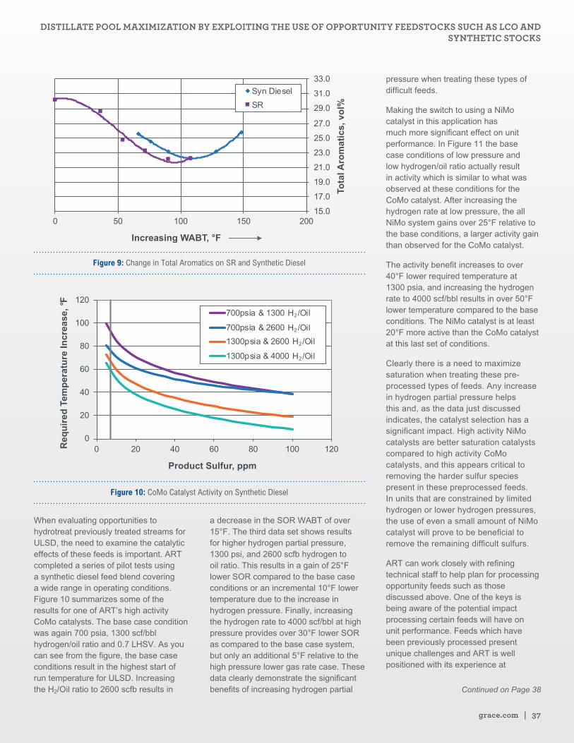
grace.com | 37
Figure 9: Change in Total Aromatics on SR and Synthetic Diesel
Figure 10: CoMo Catalyst Activity on Synthetic Diesel
When evaluating opportunities to hydrotreat previously treated streams for ULSD, the need to examine the catalytic effects of these feeds is important. ART completed a series of pilot tests using a synthetic diesel feed blend covering a wide range in operating conditions. Figure 10 summarizes some of the results for one of ART’s high activity CoMo catalysts. The base case condition was again 700 psia, 1300 scf/bbl hydrogen/oil ratio and 0.7 LHSV. As you can see from the figure, the base case conditions result in the highest start of run temperature for ULSD. Increasing the H2/Oil ratio to 2600 scfb results in
a decrease in the SOR WABT of over 15°F. The third data set shows results for higher hydrogen partial pressure, 1300 psi, and 2600 scfb hydrogen to oil ratio. This results in a gain of 25°F lower SOR compared to the base case conditions or an incremental 10°F lower temperature due to the increase in hydrogen pressure. Finally, increasing the hydrogen rate to 4000 scf/bbl at high pressure provides over 30°F lower SOR as compared to the base case system, but only an additional 5°F relative to the high pressure lower gas rate case. These data clearly demonstrate the significant benefits of increasing hydrogen partial
pressure when treating these types of difficult feeds.
Making the switch to using a NiMo catalyst in this application has much more significant effect on unit performance. In Figure 11 the base case conditions of low pressure and low hydrogen/oil ratio actually result in activity which is similar to what was observed at these conditions for the CoMo catalyst. After increasing the hydrogen rate at low pressure, the all NiMo system gains over 25°F relative to the base conditions, a larger activity gain than observed for the CoMo catalyst.
The activity benefit increases to over 40°F lower required temperature at 1300 psia, and increasing the hydrogen rate to 4000 scf/bbl results in over 50°F lower temperature compared to the base conditions. The NiMo catalyst is at least 20°F more active than the CoMo catalyst at this last set of conditions.
Clearly there is a need to maximize saturation when treating these pre-processed types of feeds. Any increase in hydrogen partial pressure helps this and, as the data just discussed indicates, the catalyst selection has a significant impact. High activity NiMo catalysts are better saturation catalysts compared to high activity CoMo catalysts, and this appears critical to removing the harder sulfur species present in these preprocessed feeds. In units that are constrained by limited hydrogen or lower hydrogen pressures, the use of even a small amount of NiMo catalyst will prove to be beneficial to remove the remaining difficult sulfurs.
ART can work closely with refining technical staff to help plan for processing opportunity feeds such as those discussed above. One of the keys is being aware of the potential impact processing certain feeds will have on unit performance. Feeds which have been previously processed present unique challenges and ART is well positioned with its experience at
Continued on Page 38
DISTILLATE POOL MAXIMIZATION BY EXPLOITING THE USE OF OPPORTUNITY FEEDSTOCKS SUCH AS LCO AND SYNTHETIC STOCKS
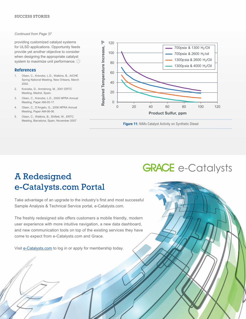
38 | Catalagram® No. 125 | Spring 2020
providing customized catalyst systems for ULSD applications. Opportunity feeds provide yet another objective to consider when designing the appropriate catalyst system to maximize unit performance.
References1. Olsen, C., Krenzke, L.D., Watkins, B., AICHE
Spring National Meeting, New Orleans, March
2002.
2. Krenzke, D., Armstrong, M., 2001 ERTC
Meeting, Madrid, Spain.
3. Olsen, C., Krenzke, L.D., 2005 NPRA Annual
Meeting, Paper AM-05-17.
4. Olsen, C., D’Angelo, G., 2006 NPRA Annual
Meeting, Paper AM-06-06.
5. Olsen, C., Watkins, B., Shiflett, W., ERTC
Meeting, Barcelona, Spain, November 2007
Figure 11: NiMo Catalyst Activity on Synthetic Diesel
Continued from Page 37
A Redesigned e-Catalysts.com PortalTake advantage of an upgrade to the industry’s first and most successful
Sample Analysis & Technical Service portal, e-Catalysts.com.
The freshly redesigned site offers customers a mobile friendly, modern
user experience with more intuitive navigation, a new data dashboard,
and new communication tools on top of the existing services they have
come to expect from e-Catalysts.com and Grace.
Visit e-Catalysts.com to log in or apply for membership today.
SUCCESS STORIES
Parkland Refining and Grace Collaborate to Increase FCCU Catalyst Circulation CapacityDavid Hunt Senior Principal FCC Technologist, Refining Technologies W. R. Grace & Co.
Drey Holder FCC Technical Service Manager, Refining Technologies W. R. Grace & Co.
Chad Cavan Technical Sales Manager, Refining Technologies W. R. Grace & Co.
Jonathan Bain Process Engineer Parkland Refining
Alvaro Aragon Sr. Process Engineer Parkland Refining
Christopher Hives Operations Assistant Parkland Refining
Parkland Refining operates a 55,000-bpd refinery located in Burnaby,
British Columbia near the city of Vancouver. The FCCU processes a
nominal 17,500 bpd of feedstock consisting of Vacuum Gas Oil and
Atmospheric Tower Bottoms. The FCCU was revamped several years ago
to a side-by-side combustor design (Figure 1). A back-mix catalyst cooler
is positioned at the bottom of the upper regenerator and regenerated
catalyst is withdrawn from the side of the upper regenerator into a
slanted standpipe. Coke combustion occurs in the separate combustor
(lower regenerator) which transports regenerated catalyst into the
upper regenerator. Modern feed injectors, riser termination device and
packed stripper design are utilized on the oil side of the FCCU. Fresh and
purchased equilibrium catalyst are used at the Parkland FCCU. Since a
tube failure in 2018 the catalyst cooler has not been in operation.
The unit began to be limited by regenerated catalyst slide valve (RCSV)
differential pressure (dP) in 2018 while using a competitor’s catalyst.
The resulting lower catalyst circulation capacity reduced the feed rate
and riser temperature that could be achieved. Parkland began using
Grace catalyst in early 2019 and offered our technical expertise to the
Parkland team to investigate the problem and restore the unit’s catalyst
circulation capacity.
Continued on Page 40
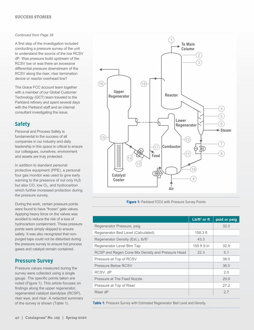
40 | Catalagram® No. 125 | Spring 2020
A first step of the investigation included conducting a pressure survey of the unit to understand the source of the low RCSV dP. Was pressure build upstream of the RCSV low or was there an excessive differential pressure downstream of the RCSV along the riser, riser termination device or reactor overhead line?
The Grace FCC account team together with a member of our Global Customer Technology (GCT) team traveled to the Parkland refinery and spent several days with the Parkland staff and an internal consultant investigating the issue.
SafetyPersonal and Process Safety is fundamental to the success of all companies in our industry and daily leadership in this space is critical to ensure our colleagues, ourselves, environment and assets are truly protected.
In addition to standard personal protective equipment (PPE), a personal four gas monitor was used to give early warning to the presence of not only H2S but also CO, low O2, and hydrocarbon which further increased protection during the pressure survey.
During the work, certain pressure points were found to have “frozen” gate valves. Applying heavy force on the valves was avoided to reduce the risk of a loss of hydrocarbon containment. Those pressure points were simply skipped to ensure safety. It was also recognized that non-purged taps could not be disturbed during the pressure survey to ensure hot process gases and catalyst remain contained.
Pressure SurveyPressure values measured during the survey were collected using a single gauge. The specific points taken are noted (Figure 1). This article focuses on findings along the upper regenerator, regenerated catalyst standpipe (RCSP), riser wye, and riser. A redacted summary of the survey is shown (Table 1).
UpperRegenerator
To MainColumn
Steam
Air
Combustor
LowerRegenerator
Reactor
Feed
CatalystCooler
1
2
3
4
10
11
1215
1413
16 18
17
9
7
8
5
6
Figure 1: Parkland FCCU with Pressure Survey Points
Lb/ft3 or ft psid or psig
Regenerator Pressure, psig 32.0
Regenerator Bed Level (Calculated) 158.3 ft
Regenerator Density (Est.), lb/ft3 43.3
Regenerator Level Btm Tap 155 ft 9 in 32.9
RCSP and Regen Cone Mix Density and Pressure Head 22.3 5.1
Pressure at Top of RCSV 38.0
Pressure Below RCSV 36.0
RCSV, dP 2.0
Pressure at The Feed Nozzle 29.9
Pressure at Top of Riser 27.2
Riser dP 2.7
Table 1: Pressure Survey with Estimated Regenerator Bed Level and Density.
Continued from Page 39
SUCCESS STORIES
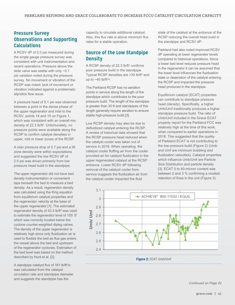
grace.com | 41
Pressure Survey Observations and Supporting CalculationsA RCSV dP of 2.0 psi measured during the single gauge pressure survey was consistent with unit instrumentation and recent operations. Pressure above the slide valve was stable with only ~0.1 psi variation noted during the pressure survey. No movement or vibration of the RCSP was noted; lack of movement or vibration indicated against a problematic slip/stick flow issue.
A pressure head of 5.1 psi was observed between a point in the dense phase of the upper regenerator and inlet to the RCSV, points 14 and 15 on Figure 1, which was consistent with an overall mix density of 22.3 lb/ft3. Unfortunately, no pressure points were available along the RCSP to confirm catalyst densities in upper, mid or lower zones of the RCSP.
A riser pressure drop of 2.7 psi and a lift zone density were within expectations and suggested the low RCSV dP of 2.0 psi was driven primarily from low pressure head build in the standpipe.
The upper regenerator did not have bed density instrumentation or convenient taps beneath the bed to measure a bed density. As a result, regenerator density was calculated using the King equation from equilibrium catalyst properties and the regenerator velocity at the base of the upper regenerator [1]. The estimated regenerator density of 43.3 lb/ft3 was used to estimate the regenerator level of 155’ 9” which was correctly located below the cyclone counter-weighted dipleg valves. The density of the upper regenerator is relatively high since only fluidization air is used to fluidize the bed as flue gas enters the vessel above the bed and upstream of the regenerator cyclones. Estimation of the bed level was based on the method described by Hunt et al. [2].
A standpipe catalyst flux of 161 lb/ft2/s was calculated from the catalyst circulation rate and standpipe diameter and suggests the standpipe has the
capacity to circulate additional catalyst. Also, this flux rate is above minimum flux rates for a stable operation.
Source of the Low Standpipe DensityA RCSP density of 22.3 lb/ft3 confirms poor pressure build in the standpipe. Typical RCSP densities are >30 lb/ft3 and up to ~40 lb/ft3+.
The Parkland RCSP has no aeration points in service along the length of the standpipe which contributes to the poor pressure build. The length of the standpipe is greater than 30 ft and standpipes of this length generally require aeration to ensure stable high-pressure build [3].
Low RCSP density may also be due to defluidized catalyst entering the RCSP. A review of historical data showed that the RCSP pressure head reduced when the catalyst cooler was taken out of service in 2018. When operating, the catalyst cooler fluffing air from the cooler provided air for catalyst fluidization in the upper regenerated catalyst at the RCSP entrance. Lower RCSV dP following removal of the catalyst cooler from service suggests the fluidization air from the catalyst cooler impacted the fluid
state of the catalyst at the entrance of the RCSP reducing the overall head build in the standpipe and RCSV dP.
Parkland had also noted improved RCSV dP operating at lower regenerator levels compared to historical operations. Since a lower bed level reduces pressure head in the regenerator it can be assumed that the lower level influences the fluidization state or deaeration of the catalyst entering the RCSP and impacted the pressure head produced in the standpipe.
Equilibrium catalyst (ECAT) properties can contribute to standpipe pressure head (density). Specifically, a higher Umb/Umf traditionally produces a higher standpipe pressure build. The ratio of Umb/Umf included in the Grace ECAT property report for the Parkland FCC was relatively high at the time of this work, when compared to earlier operations in 2018. This suggested that the quality of Parkland ECAT is not contributing to the low-pressure build (Figure 2) (Umb and Umf are minimum bubbling and fluidization velocities). Catalyst properties which influence Umb/Umf are Particle Size Distribution and particle density [3]. ECAT 0 to 40-micron content was between 2 and 3 % confirming a modest retention of fines in the unit (Figure 3).
Figure 2: ECAT Umb/Umf
Continued on Page 42
PARKLAND REFINING AND GRACE COLLABORATE TO INCREASE FCCU CATALYST CIRCULATION CAPACITY
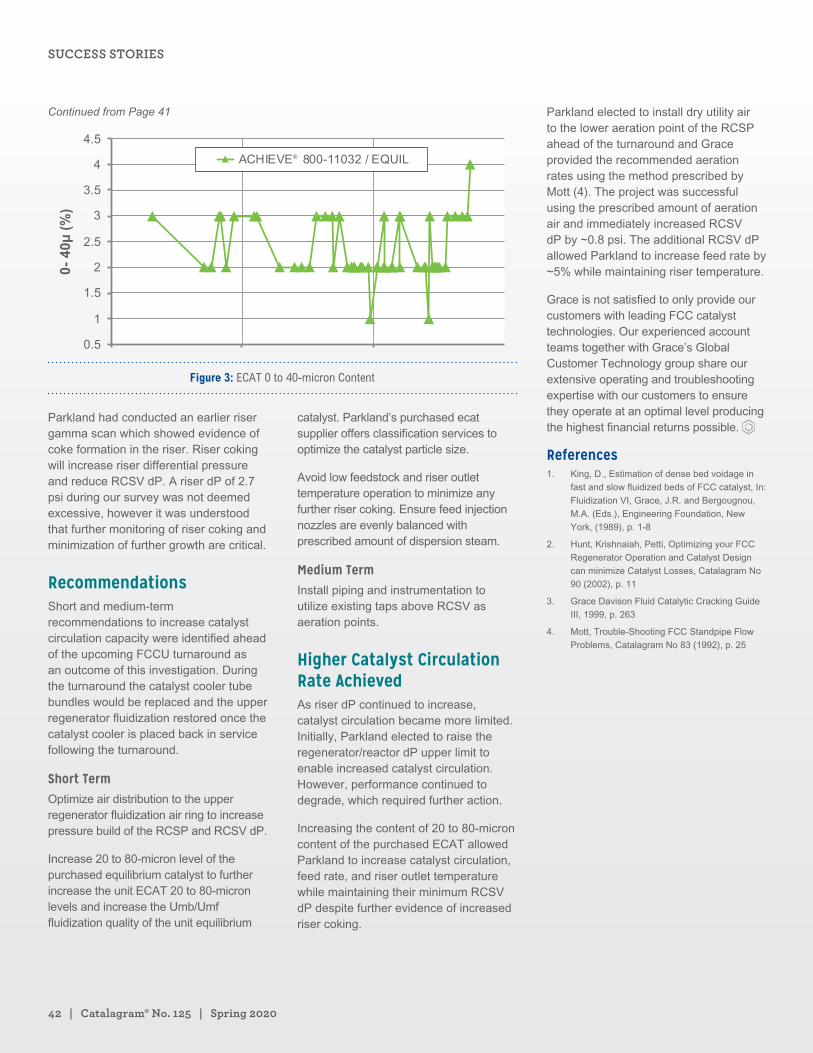
42 | Catalagram® No. 125 | Spring 2020
Figure 3: ECAT 0 to 40-micron Content
Parkland had conducted an earlier riser gamma scan which showed evidence of coke formation in the riser. Riser coking will increase riser differential pressure and reduce RCSV dP. A riser dP of 2.7 psi during our survey was not deemed excessive, however it was understood that further monitoring of riser coking and minimization of further growth are critical.
RecommendationsShort and medium-term recommendations to increase catalyst circulation capacity were identified ahead of the upcoming FCCU turnaround as an outcome of this investigation. During the turnaround the catalyst cooler tube bundles would be replaced and the upper regenerator fluidization restored once the catalyst cooler is placed back in service following the turnaround.
Short TermOptimize air distribution to the upper regenerator fluidization air ring to increase pressure build of the RCSP and RCSV dP.
Increase 20 to 80-micron level of the purchased equilibrium catalyst to further increase the unit ECAT 20 to 80-micron levels and increase the Umb/Umf fluidization quality of the unit equilibrium
catalyst. Parkland’s purchased ecat supplier offers classification services to optimize the catalyst particle size.
Avoid low feedstock and riser outlet temperature operation to minimize any further riser coking. Ensure feed injection nozzles are evenly balanced with prescribed amount of dispersion steam.
Medium TermInstall piping and instrumentation to utilize existing taps above RCSV as aeration points.
Higher Catalyst Circulation Rate AchievedAs riser dP continued to increase, catalyst circulation became more limited. Initially, Parkland elected to raise the regenerator/reactor dP upper limit to enable increased catalyst circulation. However, performance continued to degrade, which required further action.
Increasing the content of 20 to 80-micron content of the purchased ECAT allowed Parkland to increase catalyst circulation, feed rate, and riser outlet temperature while maintaining their minimum RCSV dP despite further evidence of increased riser coking.
Parkland elected to install dry utility air to the lower aeration point of the RCSP ahead of the turnaround and Grace provided the recommended aeration rates using the method prescribed by Mott (4). The project was successful using the prescribed amount of aeration air and immediately increased RCSV dP by ~0.8 psi. The additional RCSV dP allowed Parkland to increase feed rate by ~5% while maintaining riser temperature.
Grace is not satisfied to only provide our customers with leading FCC catalyst technologies. Our experienced account teams together with Grace’s Global Customer Technology group share our extensive operating and troubleshooting expertise with our customers to ensure they operate at an optimal level producing the highest financial returns possible.
References1. King, D., Estimation of dense bed voidage in
fast and slow fluidized beds of FCC catalyst, In:
Fluidization VI, Grace, J.R. and Bergougnou,
M.A. (Eds.), Engineering Foundation, New
York, (1989), p. 1-8
2. Hunt, Krishnaiah, Petti, Optimizing your FCC
Regenerator Operation and Catalyst Design
can minimize Catalyst Losses, Catalagram No
90 (2002), p. 11
3. Grace Davison Fluid Catalytic Cracking Guide
III, 1999, p. 263
4. Mott, Trouble-Shooting FCC Standpipe Flow
Problems, Catalagram No 83 (1992), p. 25
Continued from Page 41
SUCCESS STORIES
Introducing PropyleneMAX® Catalytic Cracking (PMcc®)Dilip Dharia Senior Director High Olefins FCC Program TechnipFMC Process Technology
Kenneth Krug Senior Director, Refining Technology TechnipFMC Process Technology
Siyi Lai Manager, FCC Yield Modeling TechnipFMC Process Technology
Raj Singh Senior Technologist TechnipFMC Process Technology
The demand for transportation fuels is barely
maintaining, while petrochemical demand
is increasing. Refinery units can improve
profitability by producing more petrochemicals
versus traditional transportation fuels.
PropyleneMAX® Catalytic Cracking (PMcc®) is a
commercially proven fluid catalytic process for
selectively cracking a variety of hydrocarbon
feedstocks to light olefins, particularly propylene,
isobutylene, aromatic naphtha and ethylene.
Typical feedstocks include distillates, vacuum
gas oils and residual oils. The PMcc® process
offers a reliable, low-cost route to propylene
production and allows the refiner to extend the
market range into higher margin petrochemicals.
Developed through a joint effort, Grace and
TechnipFMC offer an improved catalyst and
process designed to provide better pathways to
increase conversion of crude oil to petrochemical
feedstocks now and into the future.
Continued on Page 44
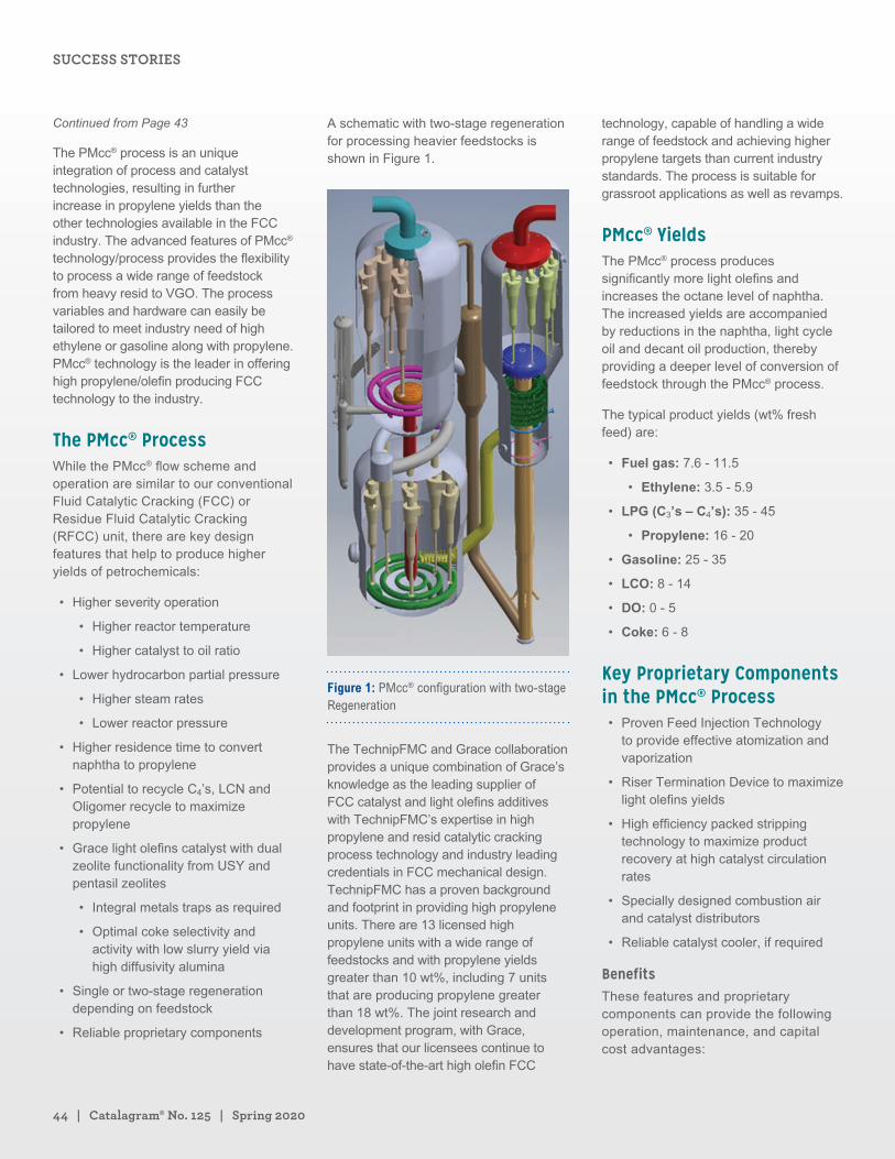
44 | Catalagram® No. 125 | Spring 2020
The PMcc® process is an unique integration of process and catalyst technologies, resulting in further increase in propylene yields than the other technologies available in the FCC industry. The advanced features of PMcc® technology/process provides the flexibility to process a wide range of feedstock from heavy resid to VGO. The process variables and hardware can easily be tailored to meet industry need of high ethylene or gasoline along with propylene. PMcc® technology is the leader in offering high propylene/olefin producing FCC technology to the industry.
The PMcc® ProcessWhile the PMcc® flow scheme and operation are similar to our conventional Fluid Catalytic Cracking (FCC) or Residue Fluid Catalytic Cracking (RFCC) unit, there are key design features that help to produce higher yields of petrochemicals:
• Higher severity operation
• Higher reactor temperature
• Higher catalyst to oil ratio
• Lower hydrocarbon partial pressure
• Higher steam rates
• Lower reactor pressure
• Higher residence time to convert naphtha to propylene
• Potential to recycle C4’s, LCN and Oligomer recycle to maximize propylene
• Grace light olefins catalyst with dual zeolite functionality from USY and pentasil zeolites
• Integral metals traps as required
• Optimal coke selectivity and activity with low slurry yield via high diffusivity alumina
• Single or two-stage regeneration depending on feedstock
• Reliable proprietary components
A schematic with two-stage regeneration for processing heavier feedstocks is shown in Figure 1.
Figure 1: PMcc® configuration with two-stage Regeneration
The TechnipFMC and Grace collaboration provides a unique combination of Grace’s knowledge as the leading supplier of FCC catalyst and light olefins additives with TechnipFMC’s expertise in high propylene and resid catalytic cracking process technology and industry leading credentials in FCC mechanical design. TechnipFMC has a proven background and footprint in providing high propylene units. There are 13 licensed high propylene units with a wide range of feedstocks and with propylene yields greater than 10 wt%, including 7 units that are producing propylene greater than 18 wt%. The joint research and development program, with Grace, ensures that our licensees continue to have state-of-the-art high olefin FCC
technology, capable of handling a wide range of feedstock and achieving higher propylene targets than current industry standards. The process is suitable for grassroot applications as well as revamps.
PMcc® YieldsThe PMcc® process produces significantly more light olefins and increases the octane level of naphtha. The increased yields are accompanied by reductions in the naphtha, light cycle oil and decant oil production, thereby providing a deeper level of conversion of feedstock through the PMcc® process.
The typical product yields (wt% fresh feed) are:
• Fuel gas: 7.6 - 11.5
• Ethylene: 3.5 - 5.9
• LPG (C3’s – C4’s): 35 - 45
• Propylene: 16 - 20
• Gasoline: 25 - 35
• LCO: 8 - 14
• DO: 0 - 5
• Coke: 6 - 8
Key Proprietary Components in the PMcc® Process• Proven Feed Injection Technology
to provide effective atomization and vaporization
• Riser Termination Device to maximize light olefins yields
• High efficiency packed stripping technology to maximize product recovery at high catalyst circulation rates
• Specially designed combustion air and catalyst distributors
• Reliable catalyst cooler, if required
BenefitsThese features and proprietary components can provide the following operation, maintenance, and capital cost advantages:
Continued from Page 43
SUCCESS STORIES
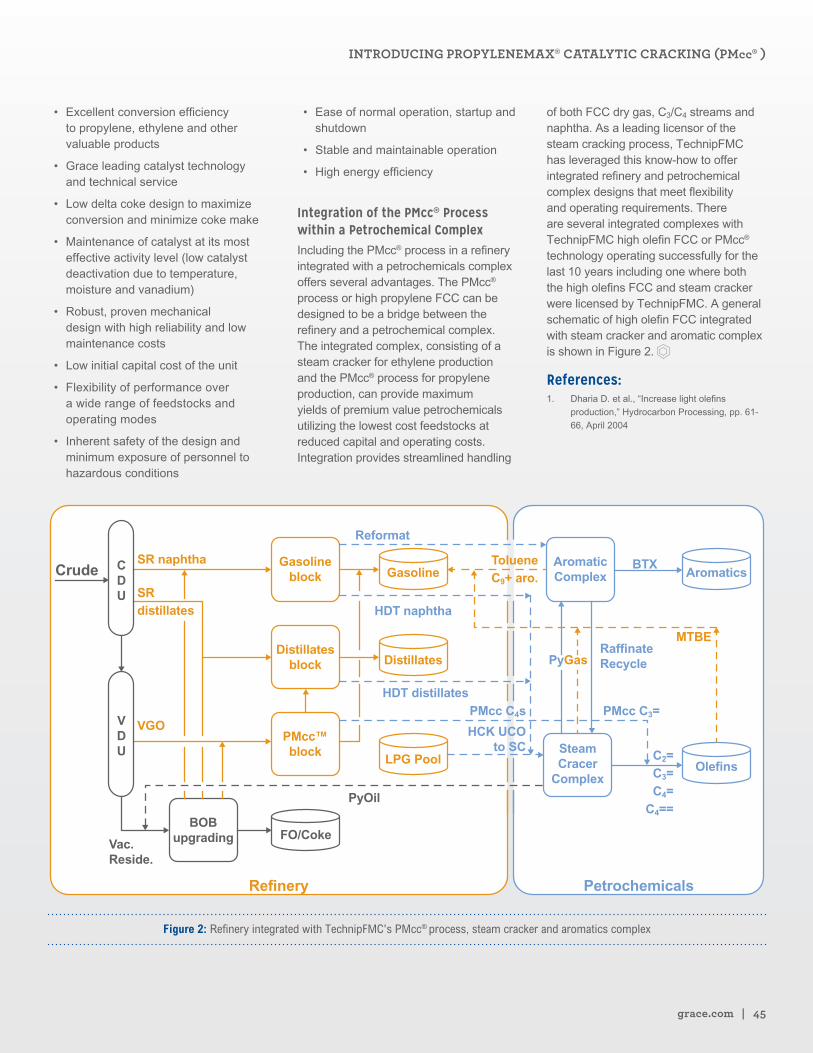
grace.com | 45
• Excellent conversion efficiency to propylene, ethylene and other valuable products
• Grace leading catalyst technology and technical service
• Low delta coke design to maximize conversion and minimize coke make
• Maintenance of catalyst at its most effective activity level (low catalyst deactivation due to temperature, moisture and vanadium)
• Robust, proven mechanical design with high reliability and low maintenance costs
• Low initial capital cost of the unit
• Flexibility of performance over a wide range of feedstocks and operating modes
• Inherent safety of the design and minimum exposure of personnel to hazardous conditions
• Ease of normal operation, startup and shutdown
• Stable and maintainable operation
• High energy efficiency
Integration of the PMcc® Process within a Petrochemical ComplexIncluding the PMcc® process in a refinery integrated with a petrochemicals complex offers several advantages. The PMcc® process or high propylene FCC can be designed to be a bridge between the refinery and a petrochemical complex. The integrated complex, consisting of a steam cracker for ethylene production and the PMcc® process for propylene production, can provide maximum yields of premium value petrochemicals utilizing the lowest cost feedstocks at reduced capital and operating costs. Integration provides streamlined handling
of both FCC dry gas, C3/C4 streams and naphtha. As a leading licensor of the steam cracking process, TechnipFMC has leveraged this know-how to offer integrated refinery and petrochemical complex designs that meet flexibility and operating requirements. There are several integrated complexes with TechnipFMC high olefin FCC or PMcc® technology operating successfully for the last 10 years including one where both the high olefins FCC and steam cracker were licensed by TechnipFMC. A general schematic of high olefin FCC integrated with steam cracker and aromatic complex is shown in Figure 2.
References:1. Dharia D. et al., “Increase light olefins
production,” Hydrocarbon Processing, pp. 61-
66, April 2004
SR naphtha
VGOVDU
CDU
Vac.Reside.
SRdistillates
Crude GasolineTolueneC9+ aro.
MTBE
Gasolineblock Aromatics
Olefins
Distillates
HDT distillates
HDT naphtha
Reformat
BTX
RaffinateRecyclePyGas
PMcc C4s PMcc C3=
C2=C3=C4=
C4==
HCK UCOto SC
LPG Pool
FO/Coke
Refinery Petrochemicals
PyOil
AromaticComplex
SteamCracer
Complex
Distillatesblock
PMcc™block
BOBupgrading
Figure 2: Refinery integrated with TechnipFMC's PMcc® process, steam cracker and aromatics complex
INTRODUCING PROPYLENEMAX® CATALYTIC CRACKING (PMcc® )
ZAVANTI™ Catalyst: Newest ZSM-5 Technology for Max Propylene UnitsBani Cipriano, Ph.D. Segment Marketing Manager, Light Olefins W. R. Grace & Co.
Udayshankar Singh, Ph.D. Principal Scientist W. R. Grace & Co.
Wu-Cheng Cheng, Ph.D. Senior Research Fellow W. R. Grace & Co.
Mike Ziebarth, Ph.D. Director Catalyst Research W. R. Grace & Co.
Refineries facing the prospect of slowing
demand for transportation fuels have shifted
their attention to growth in demand for
petrochemicals which include ethylene,
propylene and aromatics. New investments
totaling hundreds of millions of U.S. dollars have
been announced to maximize petrochemicals
from crude by refiners in Europe, Middle East,
Asia and Africa. In parallel with this trend in
our industry, Grace continues to introduce new
products for the max-propylene FCC catalyst
segment. In this article, we introduce ZAVANTI™
catalyst, our newest ZSM-5 technology and the
latest industry leading innovation for our max
C3= customers.
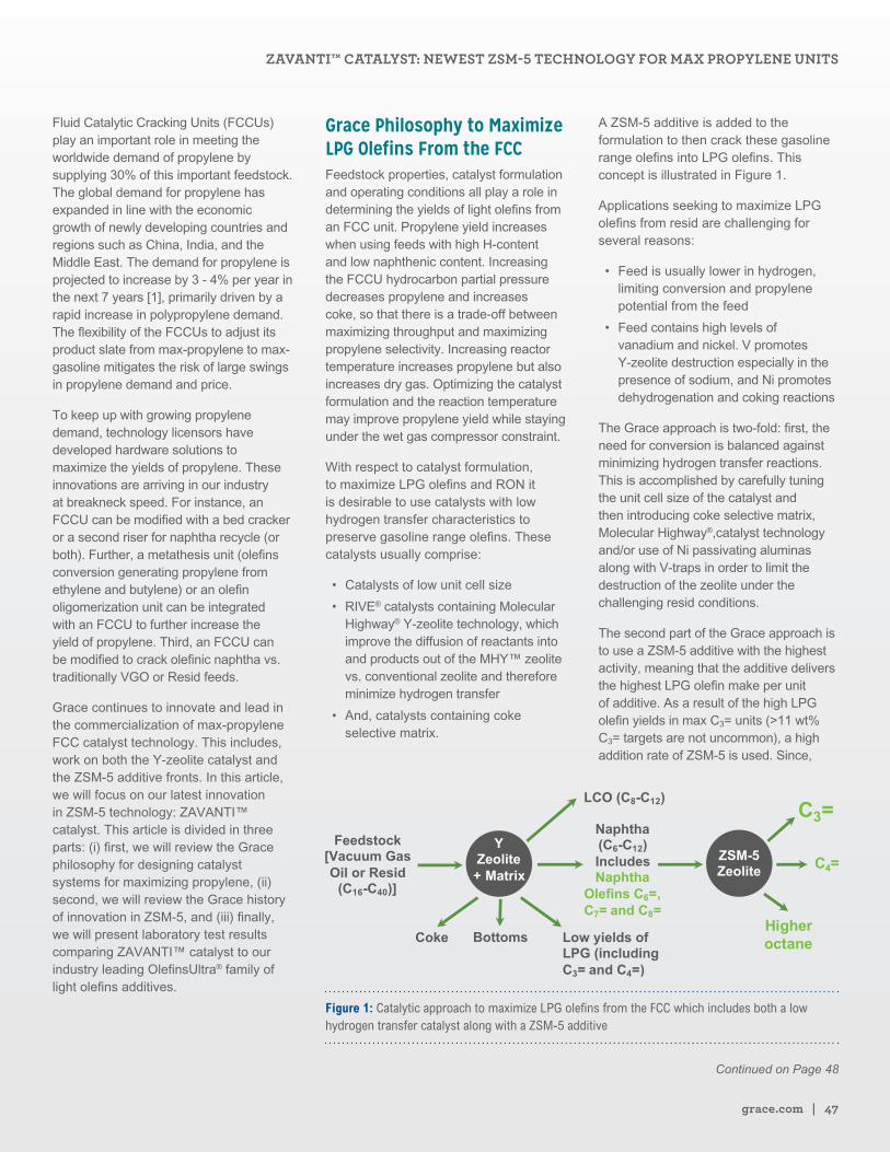
grace.com | 47
Fluid Catalytic Cracking Units (FCCUs) play an important role in meeting the worldwide demand of propylene by supplying 30% of this important feedstock. The global demand for propylene has expanded in line with the economic growth of newly developing countries and regions such as China, India, and the Middle East. The demand for propylene is projected to increase by 3 - 4% per year in the next 7 years [1], primarily driven by a rapid increase in polypropylene demand. The flexibility of the FCCUs to adjust its product slate from max-propylene to max-gasoline mitigates the risk of large swings in propylene demand and price.
To keep up with growing propylene demand, technology licensors have developed hardware solutions to maximize the yields of propylene. These innovations are arriving in our industry at breakneck speed. For instance, an FCCU can be modified with a bed cracker or a second riser for naphtha recycle (or both). Further, a metathesis unit (olefins conversion generating propylene from ethylene and butylene) or an olefin oligomerization unit can be integrated with an FCCU to further increase the yield of propylene. Third, an FCCU can be modified to crack olefinic naphtha vs. traditionally VGO or Resid feeds.
Grace continues to innovate and lead in the commercialization of max-propylene FCC catalyst technology. This includes, work on both the Y-zeolite catalyst and the ZSM-5 additive fronts. In this article, we will focus on our latest innovation in ZSM-5 technology: ZAVANTI™ catalyst. This article is divided in three parts: (i) first, we will review the Grace philosophy for designing catalyst systems for maximizing propylene, (ii) second, we will review the Grace history of innovation in ZSM-5, and (iii) finally, we will present laboratory test results comparing ZAVANTI™ catalyst to our industry leading OlefinsUltra® family of light olefins additives.
Grace Philosophy to Maximize LPG Olefins From the FCCFeedstock properties, catalyst formulation and operating conditions all play a role in determining the yields of light olefins from an FCC unit. Propylene yield increases when using feeds with high H-content and low naphthenic content. Increasing the FCCU hydrocarbon partial pressure decreases propylene and increases coke, so that there is a trade-off between maximizing throughput and maximizing propylene selectivity. Increasing reactor temperature increases propylene but also increases dry gas. Optimizing the catalyst formulation and the reaction temperature may improve propylene yield while staying under the wet gas compressor constraint.
With respect to catalyst formulation, to maximize LPG olefins and RON it is desirable to use catalysts with low hydrogen transfer characteristics to preserve gasoline range olefins. These catalysts usually comprise:
• Catalysts of low unit cell size
• RIVE® catalysts containing Molecular Highway® Y-zeolite technology, which improve the diffusion of reactants into and products out of the MHY™ zeolite vs. conventional zeolite and therefore minimize hydrogen transfer
• And, catalysts containing coke selective matrix.
A ZSM-5 additive is added to the formulation to then crack these gasoline range olefins into LPG olefins. This concept is illustrated in Figure 1.
Applications seeking to maximize LPG olefins from resid are challenging for several reasons:
• Feed is usually lower in hydrogen, limiting conversion and propylene potential from the feed
• Feed contains high levels of vanadium and nickel. V promotes Y-zeolite destruction especially in the presence of sodium, and Ni promotes dehydrogenation and coking reactions
The Grace approach is two-fold: first, the need for conversion is balanced against minimizing hydrogen transfer reactions. This is accomplished by carefully tuning the unit cell size of the catalyst and then introducing coke selective matrix, Molecular Highway®,catalyst technology and/or use of Ni passivating aluminas along with V-traps in order to limit the destruction of the zeolite under the challenging resid conditions.
The second part of the Grace approach is to use a ZSM-5 additive with the highest activity, meaning that the additive delivers the highest LPG olefin make per unit of additive. As a result of the high LPG olefin yields in max C3= units (>11 wt% C3= targets are not uncommon), a high addition rate of ZSM-5 is used. Since,
Figure 1: Catalytic approach to maximize LPG olefins from the FCC which includes both a low hydrogen transfer catalyst along with a ZSM-5 additive
Continued on Page 48
ZAVANTI™ CATALYST: NEWEST ZSM-5 TECHNOLOGY FOR MAX PROPYLENE UNITS
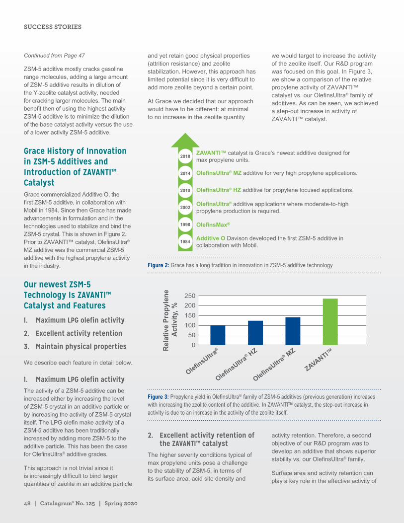
48 | Catalagram® No. 125 | Spring 2020
ZSM-5 additive mostly cracks gasoline range molecules, adding a large amount of ZSM-5 additive results in dilution of the Y-zeolite catalyst activity, needed for cracking larger molecules. The main benefit then of using the highest activity ZSM-5 additive is to minimize the dilution of the base catalyst activity versus the use of a lower activity ZSM-5 additive.
Grace History of Innovation in ZSM-5 Additives and Introduction of ZAVANTI™ CatalystGrace commercialized Additive O, the first ZSM-5 additive, in collaboration with Mobil in 1984. Since then Grace has made advancements in formulation and in the technologies used to stabilize and bind the ZSM-5 crystal. This is shown in Figure 2. Prior to ZAVANTI™ catalyst, OlefinsUltra® MZ additive was the commercial ZSM-5 additive with the highest propylene activity in the industry.
Our newest ZSM-5 Technology Is ZAVANTI™ Catalyst and Features
1. Maximum LPG olefin activity
2. Excellent activity retention
3. Maintain physical properties
We describe each feature in detail below.
1. Maximum LPG olefin activityThe activity of a ZSM-5 additive can be increased either by increasing the level of ZSM-5 crystal in an additive particle or by increasing the activity of ZSM-5 crystal itself. The LPG olefin make activity of a ZSM-5 additive has been traditionally increased by adding more ZSM-5 to the additive particle. This has been the case for OlefinsUltra® additive grades.
This approach is not trivial since it is increasingly difficult to bind larger quantities of zeolite in an additive particle
and yet retain good physical properties (attrition resistance) and zeolite stabilization. However, this approach has limited potential since it is very difficult to add more zeolite beyond a certain point.
At Grace we decided that our approach would have to be different: at minimal to no increase in the zeolite quantity
we would target to increase the activity of the zeolite itself. Our R&D program was focused on this goal. In Figure 3, we show a comparison of the relative propylene activity of ZAVANTI™ catalyst vs. our OlefinsUltra® family of additives. As can be seen, we achieved a step-out increase in activity of ZAVANTI™ catalyst.
ZAVANTI™ catalyst is Grace’s newest additive designed formax propylene units.
OlefinsUltra® MZ additive for very high propylene applications.
OlefinsUltra® HZ additive for propylene focused applications.
OlefinsUltra® additive applications where moderate-to-high propylene production is required.
Additive O Davison developed the first ZSM-5 additive in collaboration with Mobil.
Figure 2: Grace has a long tradition in innovation in ZSM-5 additive technology
250
200
150
100
50
0Rel
ativ
e P
rop
ylen
e A
ctiv
ity,
%
ZAVANTI™
OlefinsUltra® M
Z
OlefinsUltra® H
Z
OlefinsUltra®
Figure 3: Propylene yield in OlefinsUltra® family of ZSM-5 additives (previous generation) increases with increasing the zeolite content of the additive. In ZAVANTI™ catalyst, the step-out increase in activity is due to an increase in the activity of the zeolite itself.
2. Excellent activity retention of the ZAVANTI™ catalyst
The higher severity conditions typical of max propylene units pose a challenge to the stability of ZSM-5, in terms of its surface area, acid site density and
activity retention. Therefore, a second objective of our R&D program was to develop an additive that shows superior stability vs. our OlefinsUltra® family.
Surface area and activity retention can play a key role in the effective activity of
Continued from Page 47
SUCCESS STORIES
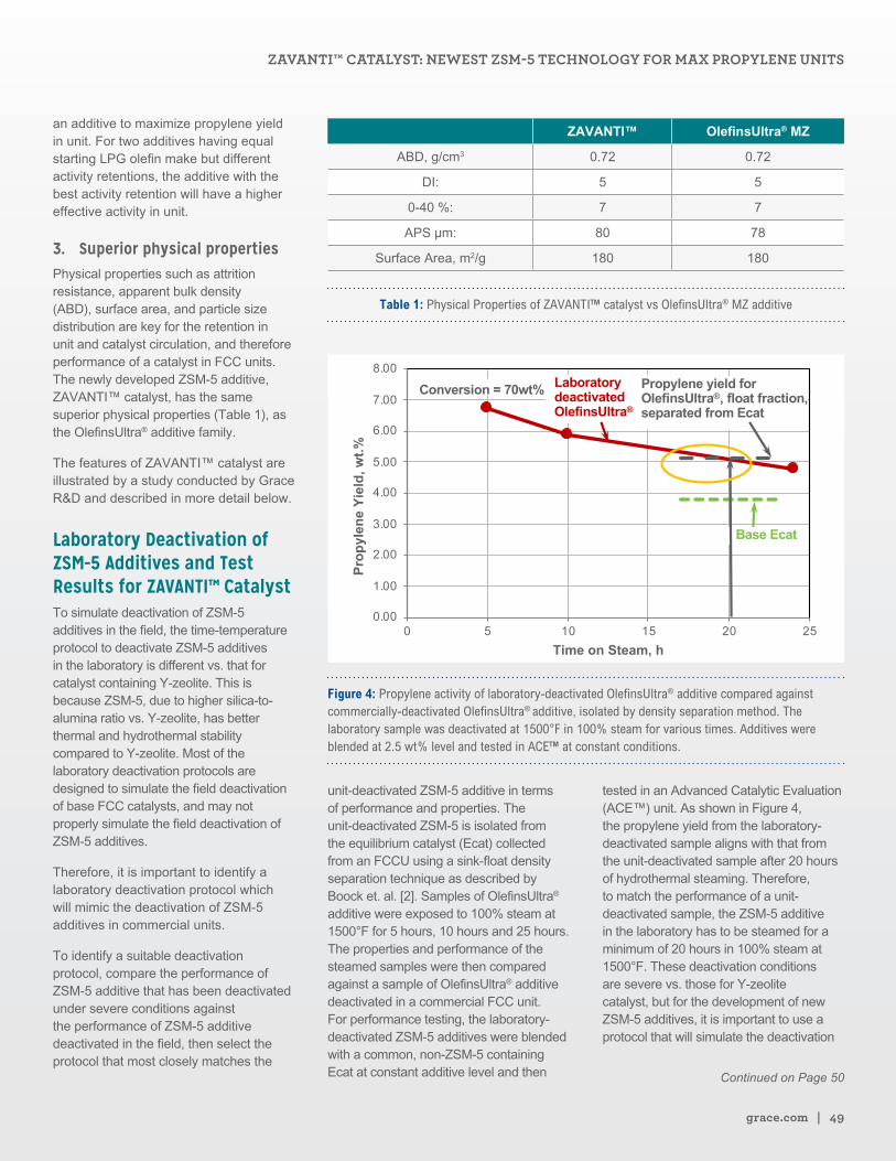
grace.com | 49
an additive to maximize propylene yield in unit. For two additives having equal starting LPG olefin make but different activity retentions, the additive with the best activity retention will have a higher effective activity in unit.
3. Superior physical propertiesPhysical properties such as attrition resistance, apparent bulk density (ABD), surface area, and particle size distribution are key for the retention in unit and catalyst circulation, and therefore performance of a catalyst in FCC units. The newly developed ZSM-5 additive, ZAVANTI™ catalyst, has the same superior physical properties (Table 1), as the OlefinsUltra® additive family.
The features of ZAVANTI™ catalyst are illustrated by a study conducted by Grace R&D and described in more detail below.
Laboratory Deactivation of ZSM-5 Additives and Test Results for ZAVANTI™ CatalystTo simulate deactivation of ZSM-5 additives in the field, the time-temperature protocol to deactivate ZSM-5 additives in the laboratory is different vs. that for catalyst containing Y-zeolite. This is because ZSM-5, due to higher silica-to-alumina ratio vs. Y-zeolite, has better thermal and hydrothermal stability compared to Y-zeolite. Most of the laboratory deactivation protocols are designed to simulate the field deactivation of base FCC catalysts, and may not properly simulate the field deactivation of ZSM-5 additives.
Therefore, it is important to identify a laboratory deactivation protocol which will mimic the deactivation of ZSM-5 additives in commercial units.
To identify a suitable deactivation protocol, compare the performance of ZSM-5 additive that has been deactivated under severe conditions against the performance of ZSM-5 additive deactivated in the field, then select the protocol that most closely matches the
ZAVANTI™ OlefinsUltra® MZ
ABD, g/cm3 0.72 0.72
DI: 5 5
0-40 %: 7 7
APS µm: 80 78
Surface Area, m2/g 180 180
Table 1: Physical Properties of ZAVANTI™ catalyst vs OlefinsUltra® MZ additive
0.00
1.00
2.00
3.00
4.00
5.00
6.00
7.00
8.00
0 5 10 15 20 25
Prop
ylen
e Yi
eld,
wt.%
Time on Steam, h
Laboratorydeactivated OlefinsUltra®
Conversion = 70wt% Propylene yield for OlefinsUltra®, float fraction, separated from Ecat
Base Ecat
Figure 4: Propylene activity of laboratory-deactivated OlefinsUltra® additive compared against commercially-deactivated OlefinsUltra® additive, isolated by density separation method. The laboratory sample was deactivated at 1500°F in 100% steam for various times. Additives were blended at 2.5 wt% level and tested in ACE™ at constant conditions.
unit-deactivated ZSM-5 additive in terms of performance and properties. The unit-deactivated ZSM-5 is isolated from the equilibrium catalyst (Ecat) collected from an FCCU using a sink-float density separation technique as described by Boock et. al. [2]. Samples of OlefinsUltra® additive were exposed to 100% steam at 1500°F for 5 hours, 10 hours and 25 hours. The properties and performance of the steamed samples were then compared against a sample of OlefinsUltra® additive deactivated in a commercial FCC unit. For performance testing, the laboratory-deactivated ZSM-5 additives were blended with a common, non-ZSM-5 containing Ecat at constant additive level and then
tested in an Advanced Catalytic Evaluation (ACE™) unit. As shown in Figure 4, the propylene yield from the laboratory-deactivated sample aligns with that from the unit-deactivated sample after 20 hours of hydrothermal steaming. Therefore, to match the performance of a unit- deactivated sample, the ZSM-5 additive in the laboratory has to be steamed for a minimum of 20 hours in 100% steam at 1500°F. These deactivation conditions are severe vs. those for Y-zeolite catalyst, but for the development of new ZSM-5 additives, it is important to use a protocol that will simulate the deactivation
Continued on Page 50
ZAVANTI™ CATALYST: NEWEST ZSM-5 TECHNOLOGY FOR MAX PROPYLENE UNITS
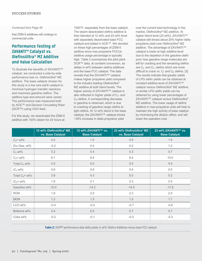
50 | Catalagram® No. 125 | Spring 2020
that ZSM-5 additives will undergo in commercial units.
Performance Testing of ZAVANTI™ Catalyst vs. OlefinsUltra® MZ Additive and Value Calculation
To illustrate the benefits of ZAVANTI™ catalyst, we conducted a side-by-side performance test vs. OlefinsUltra® MZ additive. The base catalyst chosen for this study is a low rare earth catalyst to minimize hydrogen transfer reactions and maximize gasoline olefins. The additive type and amount were varied. The performance was measured both by ACE™ and Davison Circulating Riser (DCR™) using VGO feed.
For this study, we deactivated the ZSM-5 additive with 100% steam for 24 hours at
1500°F, separately from the base catalyst. The steam-deactivated olefins additive is then blended at 12 wt% and 23 wt% level with separately deactivated base FCC catalyst and tested in ACE™. We decided on these high percentages of ZSM-5 additive since max propylene FCCUs additive usage percentage is typically high. Table 2 summarizes the pilot plant DCR™ data, at constant conversion, as deltas in wt% between olefins additives and the base FCC catalyst. The data reveals that the ZAVANTI™ catalyst makes higher propylene yield compared to the industry leading OlefinsUltra® MZ additive at both blend levels. The higher activity of ZAVANTI™ catalyst is also reflected in higher yields of C2- and C4-olefins. A corresponding decrease in gasoline is observed, which is due to cracking of gasoline range olefins to light olefins. At 12 wt% blend in the base catalyst, the ZAVANTI™ catalyst shows ~30% increase in delta propylene yield
over the current best technology in the market, OlefinsUltra® MZ additive. At higher blend level (23 wt%), ZAVANTI™ catalyst still shows about 20% higher delta propylene yield over OlefinsUltra® MZ additive. The advantage of ZAVANTI™ catalyst is lower at high additive level due to the depletion in the gasoline olefin pool: less gasoline range molecules are left for cracking and the remaining olefins are C5- and C6- olefins which are more difficult to crack vs. C7 and C8 olefins. [3] The results indicate that greater yields of LPG olefin yields can be obtained at constant additive level of ZAVANTI™ catalyst versus OlefinsUltra® MZ additive, or similar LPG olefin yields can be obtained by using lower percentages of ZAVANTI™ catalyst versus OlefinsUltra® MZ additive. The lower usage of olefins additive in max-propylene units will help to maintain the high activity of base catalyst by minimizing the dilution effect, and will lower the operation cost.
12 wt% OlefinsUltra® MZ vs. Base Catalyst
12 wt% ZAVANTI™ vs. Base Catalyst
23 wt% OlefinsUltra® MZ vs. Base Catalyst
23 wt% ZAVANTI™ vs. Base Catalyst
C2= wt% 0.4 1.0 0.9 1.8
Dry Gas, wt% -0.2 0.4 0.2 1.2
C3 wt% 0.2 0.4 0.3 0.7
C3= wt% 6.1 8.4 8.4 10.0
Total C4 wt% 4.5 5.0 5.5 5.9
iC4 wt% 0.6 0.6 0.4 0.5
Total C4= wt% 3.8 4.3 5.0 5.2
iC4= wt% 1.8 2.1 2.3 2.5
Gasoline wt% -10.5 -14.2 -14.5 -17.6
RON 1.8 2.0 2.3 2.5
MON 1.2 1.5 1.5 1.7
LCO wt% -0.4 -0.4 -0.7 -0.6
Bottoms wt% 0.4 0.5 0.7 0.7
Coke wt% -0.2 -0.1 -0.2 -0.3
Table 2: DCR™ performance data delta yields in wt% Olefins Additives minus base FCC catalyst.
Continued from Page 49
SUCCESS STORIES
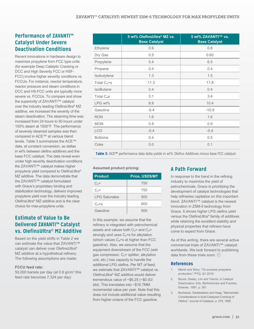
grace.com | 51
Performance of ZAVANTI™ Catalyst Under Severe Deactivation ConditionsRecent innovations in hardware design to maximize propylene from FCC type units (for example Deep Catalytic Cracking or DCC and High Severity FCC or HSF-FCC) involve higher severity conditions vs. FCCUs. For instance, reactor temperature, reactor pressure and steam conditions in DCC and HS-FCC units are typically more severe vs. FCCUs. To compare and show the superiority of ZAVANTI™ catalyst over the industry leading OlefinsUltra® MZ additive, we increased the severity of the steam deactivation. The steaming time was increased from 24 hours to 50 hours under 100% steam at 1500°F. The performance of severely steamed samples was then compared in ACE™ at various blend levels. Table 3 summarizes the ACE™ data, at constant conversion, as deltas in wt% between olefins additives and the base FCC catalyst. The data reveal even under high severity deactivation conditions the ZAVANTI™ catalyst makes higher propylene yield compared to OlefinsUltra® MZ additive. The data demonstrate that the ZAVANTI™ catalyst formulated with Grace’s proprietary binding and stabilization technology, delivers improved propylene yield over the industry leading OlefinsUltra® MZ additive and is the clear choice for max-propylene units.
Estimate of Value to Be Delivered ZAVANTI™ Catalyst vs. OlefinsUltra® MZ AdditiveBased on the yield shifts in Table 2 we can estimate the value that ZAVANTI™ catalyst can deliver over OlefinsUltra® MZ additive at a hypothetical refinery. The following assumptions are made:
FCCU feed rate: 50,000 barrels per day (at 0.9 g/cm3 this feed rate becomes 7,324 per day)
5 wt% OlefinsUltra® MZ vs. Base Catalyst
5 wt% ZAVANTI™ vs. Base Catalyst
Ethylene 0.6 0.8
Dry Gas 0.5 0.60
Propylene 5.4 6.5
Propane 0.4 0.4
Isobutylene 1.3 1.5
Total C4=s 11.3 11.8
IsoButane 0.4 0.4
Total C4s 3.1 3.4
LPG wt% 8.8 10.4
Gasoline -9.4 -10.9
RON 1.6 1.6
MON 0.8 0.9
LCO -0.4 -0.4
Bottoms 0.4 0.5
Coke 0.0 0.1
Table 3: ACE™ performance data delta yields in wt% Olefins Additives minus base FCC catalyst.
Assumed product pricing:
Product Price, USD$/MT
C2= 750
C3= 750
LPG Saturates 500
C4=s 600
Gasoline 500
In this example, we assume that the refinery is integrated with petrochemical assets and values both C2= and C3= strongly and uses C4=s for alkylation (which values C4=s at higher than FCC gasoline). Also, we assume that the equipment downstream of the FCC (wet gas compressor, C3= splitter, alkylation unit, etc.) has capacity to handle the additional LPG olefins. Per MT of feed, we estimate that ZAVANTI™ catalyst vs. OlefinsUltra® MZ additive would deliver tremendous value of ~$6.25 (~$0.92/bbl). This translates into ~$16.7MM incremental value per year. Note that this does not include additional value resulting from higher octane of the FCC gasoline.
A Path ForwardIn response to the trend in the refining industry to maximize the yield of petrochemicals, Grace is prioritizing the development of catalyst technologies that help refineries capitalize on this important trend. ZAVANTI™ catalyst is the newest innovation in ZSM-5 technology from Grace. It shows higher LPG olefins yield versus the OlefinsUltra® family of additives while retaining the excellent stability and physical properties that refiners have come to expect from Grace.
As of this writing, there are several active commercial trials of ZAVANTI™ catalyst worldwide. We look forward to publishing data from these trials soon.
References1. Marsh and Wery, "On-purpose propylene
production," PTQ, Q1 2019.
2. Boock, Deady, Lim and Yaluris, in Catalyst
Deactivation, Eds. Bartholomew and Fuentes,
Elsevier, 1997, p. 367.
3. Buchanan, Santiesteban and Haag, "Mechanistic
Considerations in Acid-Catalyzed Cracking of
Olefins," Journal of Catalysis, p. 279, 1996.
ZAVANTI™ CATALYST: NEWEST ZSM-5 TECHNOLOGY FOR MAX PROPYLENE UNITS
Are You Ready for IMO 2020?
Whether your goals are handling difficult feeds or producing more diesel, Advanced Refining Technologies (ART) offers you a better perspective on hydroprocessing.
Partner with us to meet IMO 2020 regulations head on and come out ahead. ART is the proven leader in providing excellent solutions for today’s refining industry challenges.
• High Si Capacity Solutions for Coker Naphtha
• High Metals Capacity Solutions for FCC Pretreat
• Distillate Selective Catalysts for Increasing Diesel Demand
• High Metals Capacity Hydrocracking Solutions
• High Metals Capacity Catalysts for Opportunity RDS and EBR Feeds
• Specialized Catalyst(s) for DAO Containing EBR Feeds
Visit arthydroprocessing.com
Are You Ready for IMO 2020?
GRACE®, CATALAGRAM®, RIVE®, FUSION®, AURORA®, MOLECULAR HIGHWAY®, OLEFINSULTRA®, and OLEFINSMAX® are trademarks, registered in the United States and/or other countries, of W. R. Grace & Co.-Conn. TALENT | TECHNOLOGY | TRUST™, ZAVANTI™, MHY™, and DCR™ are trademarks of W. R. Grace & Co.-Conn.
ART®, ART & Design®, and ADVANCED REFINING TECHNOLOGIES® are trademarks, of Advanced Refining Technologies LLC. ART HYDROPROCESSING™ is a trademark of Advanced Refining Technologies LLC.
CHEVRON & Design® and ICR® are trademarks, registered in the United States and/or other countries, of Chevron Intellectual Property LLC. LC-FINING™ is a trademark of Chevron Intellectual Property LLC.
PMcc® is a trademark, registered in the United States and/or other countries, of TECHNIP Process Technology, LLC. PROPYLENEMAX™ is a trademark of TECHNIP Process Technology, LLC.
ECOVADIS & Design is a trademark, registered in the United States and/or other countries, of Ecovadis.
SHARC® is a trademark, registered in the United States and/or other countries, of Shell Trademark Management B.V.
ACE™ is a trademark of Kayser Technology.
TWITTER & Design® is a trademark, registered in the United States and/or other countries, of Twitter, Inc.
LINKEDIN & Design® is a trademark, registered in the United States and/or other countries, of LinkedIn Corporation.
The CATALAGRAM® is an independent publication and is not affiliated with, nor has it been authorized, sponsored, or otherwise approved by Parkland Refining, Stockholm University, I.G. Farber, Unocal, Petro Ecuador, The SASB Foundation, LUKOIL, and BREF.
This trademark listing has been compiled using available published information as of the date of this publication and may not accurately reflect current trademark ownership or status. © Copyright W. R. Grace & Co.-Conn.