Embed Size (px)
Citation preview
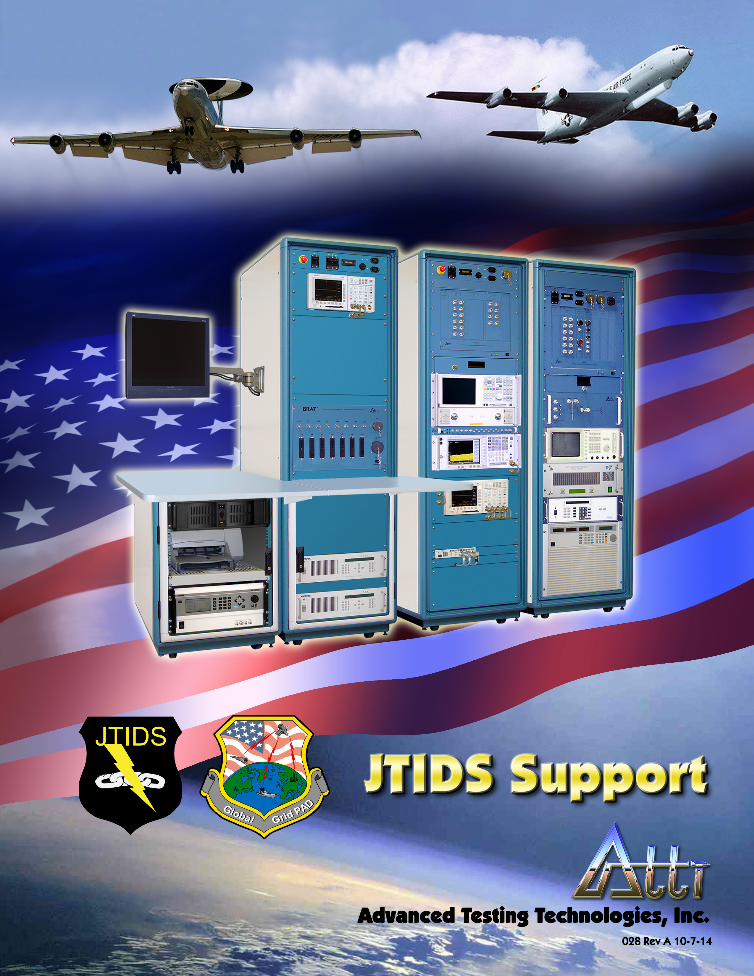
The Benchtop Reconfigurable Automatic Tester: The Key to Effecting Both Vertical and Horizontal Test Integration
The BRAT® can support the testing of multiple electronic systems from the same aircraft and multiple electronic systems from multiple aircraft• This broad capability is available for the first time due to significant advances in tester technology - VXI standard bus architecture reduces the cost and size of test instrumentation - Dozens of commercial vendors produce test instruments in accordance with this standard - PC computing power has increased by orders of magnitude - BRAT® TCASE™ Operating System creates a new benchmark in test software• The BRAT® was developed because of broad market demand - It is a true, commercial-off-the-self (COTS) tester - It dovetails perfectly with reduced DoD budgets which dictate the maximum use of lower cost COTS equipment
The BRAT® is available in a depot version and a functionally equivalent transportable version• Transportable version allows tester deployment on a single pallet• The same test program software will run with identical results at both the deployed location and the depot• For the first time this eliminates the significant problem of returning good units to the depot - Test program runs on the transportable BRAT® to perform GO/NO GO testing - Same test program runs on the depot BRAT® but also includes diagnostics
Multiple systems and multiple aircraft, one tester achieves enormous economies of scale• One tester deployed with multiple aircraft and used to test multiple systems reaps significant savings - Reduced manpower for operation at deployed site - Reduced shipment costs during deployment - Reduced logistics footprint• One test program developed for a system for both D-Level and Back Shop• Multiple test system users make possible cost sharing
Transportable BRAT 407

7BJ
JTIDS RF Rack (BRAT RF307BJ)Peak Power Meter • High Resolution Color Display• Front Panel Menu or IEEE Remote operation• Pulsed RF Measurements from -24 to +20dBm• CW Measurements from -34 to +20dBm• 1 MHz Sampling Rate• 1 GHz internal Calibrator
Peak Power Sensor • Power Measurement -40 to +20 dBm• Risetimes < 100n Sec• VSWR 1.15:1
Frequency Hopping Synthesizer• Front Panel Controls or BCD Remote operation• Frequency Hopping < 1u Sec• Frequency Range .01 to 4.6 GHz• Power Output to 10 dBm• Direct Analog Synthesis using 10 MHz Source
Power Amplifier• Frequency Range .85 to 1.45 GHz• Power Output 100 Watts (50 dBm) min• Input Power 1m Watts (0 dBm) max• Input VSWR 2:1• Output VSWR 1.3:1• Harmonics Suppression -30 dBC• Spurious Suppression -60 dBC
RF Interface UnitRFIU Controller Module and Mainframe• IEEE-• Rece
data
RF Interface Unit (continued)• Contains 68000 series microprocessor & associated RAM/ROM• 8 slot mainframe for RFIU plug-in modules• Provides cooling, power and inter-module communication
bus
L-Band Signal Conditioning Module• Signal Switching From DC to 2 GHz• Narrow Band Amplification• Programmable Attenuation• Mixer Up Conversion for 75 MHz, 273MHz & L-Band Synthesis• Mixer Down Conversion for 75 MHz, 273MHz & L-Band
Analysis• RF Detection Diodes• YIG Oscillator for BIT Testing
CPSM Modulator/Demodulator Module• Signal Switching From DC to 1 GHz• Noise Source for Noise Injection• Continuous Phase Shift Modulator (CPSM) for Link-16
Messages Simulation• Continuous Phase Shift Modulation Demodulator for
Link-16 Messages Analysis• RF Detection Diode for BIT Testing
Reference generator Module• 10 MHz Input Phase Locked to Standard RF Rack• 1.5, 2.5, 5, 8, 10, 12, 73.75 and 348MHz Phase Locked
Outputs for UUT and Test Equipment Frequency Reference.• RF Detection Diode for BIT Testing
BRAT 307
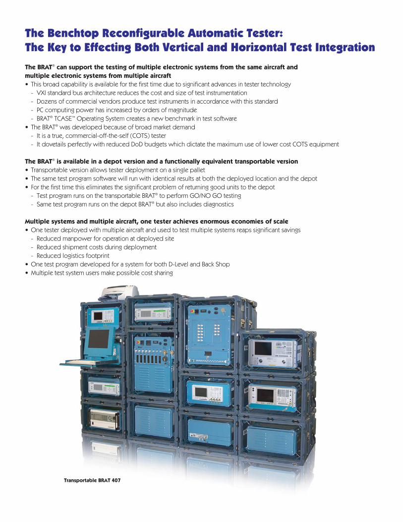
Analog/Digital Bench Top (BRAT 107)• Digital Multimeter• Digitizing Oscilloscope• Universal Counter/Timer• Arbitrary Waveform Generator• Synthesized Function/Sweep• RF Multiplexer• 64 Channel Relay Multiplexer• MIL-STD 1553 Bus Controller• Relay Matrix• 32-Bit TTL Input/Output Latch• Digital Functional Test• Dynamic Digital • DC Programmable Power Supplies• AC Programmable Power Supply
Standard RF Rack (BRAT 307)MMS Equipment• Graphics Display • 2 Synthesized Signal Generators• Frequency Extension• Power Meter • Power Sensor• Local Oscillator • Digitizer• IF Section 10 Hz to 300 KHz• IF Section 100 KHz to 3 MHz• RF Section 100 Hz to 22 GHz• Digitizing Oscilloscope
Rack Equipment• Synthesized Sweep
Signal Generator• Network Analyzer
RFIU Equipment• RF Output Module• RF Measurement Module• RF Converter Module
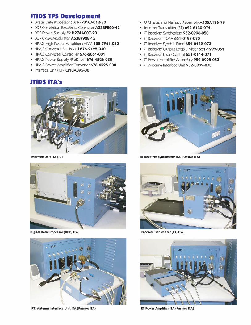
JTIDS TPS Development• Digital Data Processor (DDP) P310A012-30• DDP Correlation BaseBand Converter A538P866-42• DDP Power Supply #2 H274A007-20• DDP CPSM Modulator A538P928-15• HPAG High Power Amplifier (HPA) 622-7961-030• HPAG Converter Bus Board 676-2125-030• HPAG Converter Controller 676-2061-001• HPAG Power Supply /PreDriver 676-4526-030• HPAG Power Amplifier/Converter 676-4525-030• Interface Unit (IU) K310A095-30
• IU Chassis and Harness Assembly A405A136-79• Receiver Transmitter (RT) 622-6130-074• RT Receiver Synthesizer 952-0996-050• RT Receiver TDMA 651-0123-070• RT Receiver Synth L-Band 651-0142-073• RT Receiver Output Loop Divider 651-1299-051• RT Receiver Loop Control 651-0144-071• RT Power Amplifier Assembly 952-0998-053• RT Antenna Interface Unit 952-0999-070
Interface Unit ITA (IU) RT Receiver Synthesizer ITA (Passive ITA)
Receiver Transmitter (RT) ITADigital Data Processor (DDP) ITA
JTIDS ITA's
RT Power Amplifier ITA (Passive ITA)(RT) Antenna Interface Unit ITA (Passive ITA)

Background of Electronic TestingGeneralElectronics now plays a dominant role in virtually every product from watches and calculators to TVs and games to computers, airplanes and military weapons systems. These electronic systems have become increasingly more complex with every passing day. Their circuit density and speed factors increase at seemingly exponential rates. As reliable as these systems are, from time to time they malfunction. Whereas years ago such a malfunctioning system could be repaired by a technician using manual instrumentation, today this is impossible.
Today the use of a sophisticated electronic testing system, commonly referred to as ATE (Automatic Test Equipment), is an absolute must. ATE ascertains whether an electronic system, subsystem, module or printed circuit board is operating correctly and, if not, identifies what part of the unit is faulty and should be removed and replaced.
Production TestingATE has many uses during the life of an electronic product or system. First it is used during the product build cycle on a production floor.
• The usual scenario is for ATE to test the incoming integrated circuits (ICs) used to populate an assembly commonly referred to as a printed circuit board (PCB) or module.
• A different type of ATE then tests the populated PCB.
• When a number of PCBs are assembled into a subsystem or black box, again ATE is utilized.
• Finally, if a number of subsystems are assembled into a system, once more ATE is used to ascertain proper functioning.
Maintenance TestingOnce a system (e.g., computer, aircraft, medical electronics, weapon system) is in use, ATE must again be employed when the system malfunctions.
• Usually ATE which either "stands alone" or is built into the system (built-in-test or BIT) ascertains if the system is functioning correctly and, if not, identifies which subsystem is faulty and thus should be replaced.
• The faulty subsystem must then be tested on the same or different ATE to identify which of its PCBs or modules is to be replaced.
• Finally, that PCB or module must be tested to determine which IC or ICs are to be replaced. In short, ATE has become a total necessity in today’s increasingly complex, electronics-dominated world. Without ATE, electronic systems can neither be manufactured or maintained.

Background of Electronic Testing (continued)Available Types of ATESome ATE systems are specifically designed for one of the testing niches discussed above (e.g. PCB testing on the production floor, subsystem testing in the maintenance environment, etc.). Some are aimed only at the commercial sector and others only for the military market. Some are for fixed installations and others are portable in nature. Most have a rigid structure which qualifies them only for a specific testing application and which makes it difficult for them to cope with evolutionary changes with time in the suite of units to be tested. The same rigid structure also hinders this type of ATE if new products with some different test requirements were to be introduced into the picture.
BRAT® Unique AdvantagesThe BRAT®, however, utilizes an open architecture for both its hardware and software. This approach has numerous advantages including the following:
• The flexibility realized allows BRAT® to be used in virtually any test situation in the manufacturing or maintenance environments.
• The Unit Under Test (UUT) suite may physically be hybrids, boards, modules, subsystems or systems.
• Initially, the user need procure only the test assets required to accommodate his or her UUT suite as currently identified; this keeps the initial cost low.
• Additional test assets may be added with ease if test requirements change with time.
• The test spectrum may encompass any combination of digital, analog, RF and/or EO test capability.
• The entire spectrum of digital, analog, RF and EO test capability functions under a single, coherent ATE operating software system called TCASE™.
• The modularity and open architecture of both hardware and software assets are upgradeable with industry advancements over time, thus essentially eliminating tester obsolescence.
ATTI Company ProfileThe corporation:• Has designed, developed and manufactured ATE since 1987• Has delivered and supported many test systems in both the commercial and military sectors• Is an innovator in developing and implementing VXI technology solutions• Has developed over one thousand test program sets, covering the test spectrum from simple to extremely complex• Has numerous satisfied customers, including:- Agusta, Italy - Lockheed Martin- Boeing - NATO- Esdas, Turkey - Northrop Grumman- Havelsan, Turkey - Palomar Products, Inc.- Hellenic Air Force - Royal Saudi Air Force- Japanese Air Force - US Air Force- KLM Royal Dutch Airlines - US Navy
ATTI Worldwide SupportThe corporation:• Has developed Obsolescence Mitigation Replacement (OMR) technology which represents ATTI's corporate commitment to customer use and TPS investment in our test systems• Has delivered BRAT test systems worldwide• Offers one of the most experienced service, training and support teams in the world• Has worked with our customers solving diverse test challenges in digital, analog, and RF applications• Is committed to total hardware and software support including service, spares, upgrades, documentation, training, and configuration control• Has the financial efficacy to guarantee long-term commitments
ATTI OfficesCorporate Headquarters 110 Ricefield Lane, Hauppauge, NY 11788,phone: (631) 231-8777, 1-800-ATTI-VXI, fax: (631) 231-7174www.attinet.com
Field Offices
Warner Robins, GA 127 Osigian Blvd., Warner Robins, GA 31088 phone: (478) 953-6356, fax: (478) 953-6494
Oklahoma City, OK 4600 SE 29th Street, Suite 530, Del City, OK 73115 phone: (405) 670-0384, fax: (405) 670-0388
Layton, UT 2985 N 935 E, Suite 1, Layton, UT 84041 phone: (801) 771-7259