Embed Size (px)
Citation preview

The Basics for Bedside Nursing
Karen Donatello, RN, RCIS, CCDS

Financial Relationships
Device Check Specialist
Karen Donatello, RN, RCIS, CCDS
Objectives:
• Identify the operational characteristics of implantable Pacemaker, ICD, and CRT systems
• Demonstrate an understanding of how
the presence of implantable devices impact patient care

A Quick Review

The Electrical System of the Heart

Common Conduction Abnormalities
Bradycardia
To slow
Tachycardia
To fast
Dys-synchrony
Unequal
contraction
http://www.emedu.org/ecg/lbbb.htm

Conduction Abnormalities Cause
Syncope or pre-syncope
Dizziness
Congestive heart failure
Mental confusion
Palpitations
Shortness of breath
Exercise intolerance

What’s the Same & What’s Different?

Implantable Devices Treat
Conduction System Abnormalities
Bradycardia
Tachycardia
Dys-synchrony

Pacemakers
Support the heart rate
make a heart beat
Sense
see a native heart beat
Provide physiologic heart rates
Provide diagnostic information
Everything a Pacemaker does plus…..
Treat life threatening arrhythmias Pacing Shock
ICDs

What exactly is Cardiac Re-synchronization?

Delayed electrical conduction results in late contraction of the left ventricle
Ventricular Dyssynchrony

Re-synchronization
Goal
Simultaneous stimulation of both ventricles
Synchronized contraction

Benefits of a CRT Device Functions the same as a Pacemaker / ICD does plus…
Optimization of hemodynamic performance
Improve contraction pattern
Reduce paradoxical septal motion
Improve LV regional wall motion
Improve Left Ventricular Ejection Fraction
Symptom improvement

Components

Power Source
Housed inside the device or “can”
Battery
Circuitry
Hermetically sealed
Elective replacement means a brand new can

Leads Attach to the “can”
Deliver energy to the heart
See or sense native heart beats
Epicardial
Transvenous

Transvenous lead insertion sites Internal/external jugular
veins
Used when access is limited
Subclavian/Cephalic veins Most common for
implantable devices
Brachial/Femoral veins
Usually for temporary wires

How many wires?
Single
Dual
Cardiac Re-Synchronization
CRT

A Closer Look…..

Terminology
Asynchronous
Stimulation
Detect Rate VVI
Capture
Threshold
Lower Rate Limit
DDD
Anti-Tachycardia Pacing High Energy
Shock Sensing
Magnet Operation

Chamber(s) Paced
A = atrium
V = ventricle
D = dual (both atrium and ventricle)
O = none
1st Letter
Chamber(s) Sensed
A = atrium
V = ventricle
D = dual
O = none
2nd Letter
Response to Sensing
I = inhibit (Demand mode)
T = triggered
D = dual
O = none (Asynch)
3rd Letter
V V I
Chamber paced
Chamber sensed
Action or response to a sensed event
NBG code: Language of devices 4th Letter
R = Rate Response
R Rate Response on

VVI 1st “V” = Chamber Paced (Ventricle)
2nd “V” = Chamber Sensed (Ventricle)
3rd “I” = Inhibit

AAI 1st “A” = Chamber Paced (Atrium)
2nd “A” = Chamber Sensed (Atrium)
3rd “I” = Inhibit

AsVs ApVs
ApVp AsVp
DDD: The “four faces” of DDD pacing
1st “D” = Chamber Paced (Atrium & Ventricle)
2nd “D” = Chamber Sensed (Atrium & Ventricle)
3rd “D” = Inhibit & Trigger

Lower Rate Limit The lowest rate the pacemaker will pace the heart in the
absence of intrinsic or native events DDD
LRL 50 ppm

Detect Rate
The rate that determines when a device will initiate therapy
Can be Ventricular or Atrial therapy

Stimulation
Consists of a given amount of energy
Voltage
Delivered over a given period of time
Pulse Width
Pulse Width (ms)
Output Pulse
Voltage

Capture Depolarization of cardiac tissue in response to stimulation
or the output pulse.
Wide QRS complexes
Usually LBBB

Variations on Capture
Fusion Beat Pseudo Fusion Beat

Stimulation Threshold The minimum output pulse needed to consistently
capture cardiac tissue
Determined through manual or automatic testing
Output pulse is incrementally decreased until capture is lost
Energy safety margin is 2-3 times the threshold.
1.0V 0.5V 0.25V

Stimulation Threshold Influences
Changes in electrolyte balance within the body Dialysis
Severe acid/base imbalances
Drug and / or dosage changes
Class IC agents pacing thresholds
Flecainide, Encainide & Propafenone
Class I agents may also defibrillation thresholds
Changes at the tissue / lead interface
Ischemia
Scar tissue

Sensing
The ability of the device to “see” native or intrinsic heart beats
Measured in millivolts
5 (mV)
2.5 (mV)
1.25 (mV)

Sensitivity setting Inverse relationship between the sensitivity and the
programmed value
2mV setting is more sensitive than a 5mV setting
2 (mV) 5 (mV)

Anti-tachycardia Pacing therapy used to treat tachy-arrhythmias
Ventricular tachycardia
Atrial tachycardia / flutter

High Energy Shock
Programmed shock to terminate tachyarrhythmia
Ventricular Fibrillation
Fast Ventricular Tachycardia

Asynchronous Not in synchrony
Magnet Operation (in pacemakers)
Suspends sensing “closes the pacemakers eyes”
Forced pacing at a pre-determined rate

Magnet Operation & ICD’s
Detection suspended “closes the eyes of the ICD portion”
Device cannot see
Ventricular Tachycardia
Ventricular Fibrillation
Pacemaker portion of the ICD will function as programmed.

Patient Management
Evaluating ECG’s
Patient Management….. 53 year old male
Woke up feeling dizzy
Called the device clinic
History
Pulmonary Hypertension
Complete Heart Block
Advised to go to the ER

Presenting EKG

Cause for concern? Symptoms?
What do you see?
Pacing spikes without corresponding QRS.

Cause for Concern? Symptoms?
What do you see?
Pacing spikes where they don’t belong
When does it happen?
Look for a pattern

Cause for Concern? Symptoms?
What do you see? Pacing spikes where they don’t belong
Measure the spikes Spike to spike (1000 msec / 60ppm)
Ventricular undersensing
1000 msec

Symptoms?
What do you see?
Missing pacing spikes
If pacing occurs at all…..it is “tardy”…..pauses
Ventricular Oversensing
Pacing interval (as programmed)
Should pace here Should pace here
Cause for Concern?
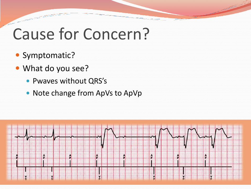
Cause for Concern? Symptomatic?
What do you see?
Pwaves without QRS’s
Note change from ApVs to ApVp

AAI(R) Mode Atrial based pacing allowing intrinsic AV conduction
Ventricular Backup Ventricular pacing only as needed in the presence of transient loss of conduction
DDD(R) Switch Ventricular support if loss of A-V conduction is persistent
Managed Ventricular Pacing (MVP)

Managed Ventricular Pacing (MVP) Functionally AAIR
Apace, Asense, Inhibit, Rate Response
Note the PR interval Normal is 120-200msec (.12-.20 seconds) 400msec (.4sec)
There must be a ventricular event between every two atrial events.

Patient Management
Medical Testing & Emergencies

Cardiac Arrest Treat the patient
Initiate CPR
Defibrillate Paddle Position: 13cm / 5in from the device
Apex / Posterior position
Evaluate the device once the patient is stable
If the patient has an Implantable defibrillator
The device will attempt to treat the arrhythmia
You may feel a slight “shock” if touching the patient
Evaluate the patient and treat accordingly.

Electromagnetic Interference (EMI) Electromagnetic energy signals from an outside source
EMI signals in the 10-60hz frequency range Overlaps the cardiac signal range
May interfere with implantable devices
Device sees the interference as native heart beats & doesn’t pace enough or paces with irregularity.
Transient mode change Noise reversion
Electrical (power-on) reset
Loss of function Nearing end of service

Lower Rate Interval
Noise Sensed
VP SR SR SR VP
Electromagnetic Interference (EMI) What does EMI look like?
Repetitive signal that overloads the sensing circuit

Electromagnetic Interference (EMI) Real life example

External Sources of EMI
Rapid advancement of technology creates unanticipated sources of EMI
Prevention: Keep technology at least 12 inches from the implantable device
Moving away from the signal returns the device to normal function
Consult with cardiologist
Call device manufacturer
Patient services

Hospital Sources of EMI Recommendation: Consult with Cardiologist prior to
initiation of therapy for risk assessment / device reprogramming.
Extracorporeal Shock Wave Lithotripsy
Electroconvulsive Shock Therapy (ECT)
Radiofrequency Ablation
TENS unit
TURP

Hospital Sources of EMI Electrocautery
Most Common Hospital Source
Bipolar preferred
Grounding plate > 15cm from device
1 sec bursts every 10 seconds recommended
Reprogramming / magnet application for dependent patients.

Hospital Sources of EMI Therapeutic Radiation risks
Device malfunction
Device failure
Precautions
Cumulative dose < 500 rads
Shielding
Device repositioning

Magnetic Resonance Imaging Facts about MRI
Standard of care for diagnosis & treatment of many comorbidities
Stroke
Various types of Cancer
Orthopedic conditions
86% of pacemaker patient are older than 65 with comorbidities that may require an MRI
As a rule, pacemaker patients have had limited to no access to this diagnostic tool.

MRI Risks
High Pacing rates during testing
Runaway Pacemaker
Delivery of RF energy down the leads to heart tissue
Historically contra-indicated & only performed in extreme circumstances under the supervision of the physician.
Recent changes
MRI conditional Pacemakers
Magnetic Resonance Imaging

Identify system compatibility with MRI
Patient ID card will identify MRI conditional system
Magnetic Resonance Imaging

X-ray
Ensures against unknown additional leads
Identifies radiopaque symbol
Magnetic Resonance Imaging

Reprogramming guidelines
Obtain order from Cardiologist
Schedule with device clinic personnel or company representative Reprogramming prior to scan
Testing and reprogramming post scan
Patient Monitoring guidelines Visual & voice communication
Continuous monitoring of oximetry or ECG NOTE: oximetry is monitored during sequences which make ECG
unreadable
External defibrillator accessible to control area staff.
Magnetic Resonance Imaging

MRI 101
Static Field
Gradient Field
RF

Scan guidelines
Horizontal cylindrical bore magnet system
1.5 Tesla
Normal operating mode
Maximum gradient slew rate performance per axis of < 200 Teslas/meter/second (T/m/s)
Whole body averaged SAR < 2dW/kg, head averaged SAR < 3.2W/kg.
Magnetic Resonance Imaging

Technology

Remote Monitoring
Transtelephonic
Rhythm strip transmitted via the telephone
Presenting
Magnet
Non-magnet
Clinician initiated

The Remote Monitor collects device data via interrogation
Data transferred from the patient’s implanted device to the Monitor
Data sent from the Monitor to a secure server via a standard telephone line
1
2
3
Clinicians review the patient’s device data using the secure website
Remote Monitoring Website based monitoring

• Allied Health professional uses monitor to interrogate implanted device.
• Transmission confirmation faxed to facility
• Transmission reviewed remotely by Monitoring Center or local clinician
• Findings discussed with facility staff and/or device follow-up clinicians
• Facility receives faxed copies of reports for their records
Hospital leverage of website based monitoring
Data can be exported to the facilities EHR
Patient’s device clinic receives transmission data for those patients currently enrolled in their remote monitoring network.
Remote Monitoring

Leveraging Technology
Improves workflow
Decreases patient wait times
Provides diagnostic information to clinician in less than half the time of traditional workflow methods.
From an average of 80 minutes to 15 minutes.
Improves quality of care
Rapid access to diagnostic data
More tools to better manage the patient’s arrhythmia status

Questions?

References Ellenbogen, K. A., & Wood, M. A. (2008). Cardiac pacing and ICDs (5th ed.). Hoboken, NJ: Blackwell Publishing Ltd.
Medtronic. (2012). CorePace resource, Basic Pacing Concepts [PowerPoint slides]. Retrieved from https://wwwp.medtronic.com/mdtConnectPortal/microsite/1581802196969/1581802196974/1581802197122
Medtronic. (2013). ICD’s resource [PowerPoint slides]. Retrieved from Https://wwwp.medtronic.com/mdtConnectPortal/therapiesprocedures/108 Umashankar Lakshmanadoss, Priya Chinnachamy and James P Daubert (2011). Electromagnetic Interference of the Pacemakers, Modern Pacemakers - Present and Future, Prof. Mithilesh R Das (Ed.), ISBN: 978-953- 307-214-2, InTech, Available from: http://www.intechopen.com/books/modern-pacemakers-present-andfuture/ electromagnetic-interference-of-the-pacemakers