Embed Size (px)
Citation preview

The AWA Review
Volume 28 • 2015
Published byTHE ANTIQUE WIRELESS ASSOCIATION
PO Box 421, Bloomfield, NY 14469-0421
http://www.antiquewireless.org

Devoted to research and documentation of the history of wireless communications.
THE ANTIQUE WIRELESS ASSOCIATIONPO Box 421, Bloomfield, NY 14469-0421
http://www.antiquewireless.org
Founded 1952, Chartered as a non-profit corporation by the State of New York.
The AWA Review
EDITOR-IN-CHIEFRobert P. Murray, Ph.D.Vancouver, BC, Canada
EDITOR FOR EUROPEAnders Widell, MD, Ph.D.
ASSOCIATE EDITORSErich Brueschke, BSEE, MD, KC9ACE
David Bart, BA, MBA, KB9YPD, Julia Bart, BA, MA
FORMER EDITORSRobert M. Morris W2LV, (silent key)William B. Fizette, Ph.D., W2GDBLudwell A. Sibley, KB2EVNThomas B. Perera, Ph.D., W1TPBrian C. Belanger, Ph.D.
OFFICERS OF THE ANTIQUE WIRELESS ASSOCIATIONDIRECTOR: Tom Peterson, Jr.DEPUTY DIRECTOR: Robert Hobday, N2EVGSECRETARY: William Hopkins, Ph.D., AA2YVTREASURER: Stan Avery, WM3DAWA MUSEUM CURATOR: Bruce Roloson, W2BDR
©2015 by the Antique Wireless Association, ISBN 978-0-9890350-2-6
Cover images: Beginning in 1938, Arvin metal cabinet sets were produced in various colors. The series ended in the mid-1950s. Article begins on page 89.
All rights reserved. No part of this publication may be reproduced, stored in a retrieval system, or transmitted, in any form or by any means, electronic, mechanical, photocopy-ing, recording, or otherwise, without the prior written permission of the copyright owner.
Book design and layout by Fiona Raven, Vancouver, BC, CanadaPrinted in Canada by Friesens, Altona, MB

Contents
■ Volume 28, 2015
FOREWORD . . . . . . . . . . . . . . . . . . . . . . . . . . . . . . . . . . . . . . . . . . . . . . . . . . . . iv
EVOLUTION OF THE AM DIALP. A. Kinzie . . . . . . . . . . . . . . . . . . . . . . . . . . . . . . . . . . . . . . . . . . . . . . . . . 1
RADIO ARCHEOLOGY, THE MT. TAM WIRELESS AND A CALL TO ACTION Bart Lee . . . . . . . . . . . . . . . . . . . . . . . . . . . . . . . . . . . . . . . . . . . . . . . . . . . . 25
EDWARD WESTON: THE MAN AND THE METERSMike Molnar . . . . . . . . . . . . . . . . . . . . . . . . . . . . . . . . . . . . . . . . . . . . . . . . 57
THE FIRST BROADCAST FM AUTO RADIO—MOTOROLA FM-900Ray Schulenberg and Olin Shuler . . . . . . . . . . . . . . . . . . . . . . . . . . . . . . . . 73
ARVIN METAL CABINET RADIOSDan Howard . . . . . . . . . . . . . . . . . . . . . . . . . . . . . . . . . . . . . . . . . . . . . . . . 89
RESTORATION OF A TRANSMITTER FOR WHEATSTONE MAGNETO- ELECTRIC DIAL TELEGRAPHY (A LETTER TO THE EDITOR)
Franz Pichler . . . . . . . . . . . . . . . . . . . . . . . . . . . . . . . . . . . . . . . . . . . . . . . . 117
LETTER TO THE EDITORJohn B. Doolittle . . . . . . . . . . . . . . . . . . . . . . . . . . . . . . . . . . . . . . . . . . . . . 121
RADIO IN 1922: WHAT THE BOYS AND GIRLS KNEWMike Adams. . . . . . . . . . . . . . . . . . . . . . . . . . . . . . . . . . . . . . . . . . . . . . . . . 123
OLIVER LODGE’S FANCIFUL HISTORY OF THE COHERER PRINCIPLEEric P. Wenaas . . . . . . . . . . . . . . . . . . . . . . . . . . . . . . . . . . . . . . . . . . . . . . . 163
90 YEARS OF PRE-ELECTRONIC VLF-TRANSMISSIONBengt Svensson. . . . . . . . . . . . . . . . . . . . . . . . . . . . . . . . . . . . . . . . . . . . . . . 221
THE HEATHKIT DF-1 TRANSISTOR RADIO DIRECTION FINDER AND THE DF-2 AND DF-3 MODELS
Erich E. Brueschke . . . . . . . . . . . . . . . . . . . . . . . . . . . . . . . . . . . . . . . . . . . . 233
WHA MADISON—IS IT REALLY THE NATION’S OLDEST STATION?Dan Clark . . . . . . . . . . . . . . . . . . . . . . . . . . . . . . . . . . . . . . . . . . . . . . . . . . 243

iv The AWA Review
ForewordMy first introduction to the AWA Conference was in the days when it was held at the Canandaigua Inn. I arrived by bus from Rochester Airport. Everything about the conference was a delight to me. One session I particularly remember was a presentation by Bob Morris, one of the founders of The AWA Review. He was showing the waveforms at various points in an operating spark transmit-ter, using a modern oscilloscope. I was very much impressed that here was an individual who spanned the time between spark transmission technology and contemporary (at that time) technology.
In this year’s AWA Review we have a few similar examples. We have the designers of the first FM car radio. We have an individual who was in on the ground floor of one of the first broadcast stations in America, still in operation as the PBS station in Madison, WI.
This volume is again brought to you by a generous donor and AWA member who believes in the dissemination of information as a core principle of our hobby. Again we owe him a heartfelt thanks. The AWA Review is the AWA’s peer reviewed journal. The articles presented here are verified as to their factual content by one or more reviewers whose identity is not revealed to the authors. This process gives The AWA Review some extra credibility as a source of historical information. This volume exhibits a great deal of dedication and energy on the part of its authors. The result is a number of fine efforts:
■ Philip Kinzie has had a lifelong career as an instrumentation engineer on civil and military aircraft. He also had a lifelong interest in radio which began when he was in elementary school. He has written some books and many articles, and his reflections about the components that were available at various points in time became the focus of this article.
■ Bart Lee stretches our imaginations this year with an unconventional topic. He investigates the wireless achievements of about a century ago by using anthropological methods. He offers us an anthropology of radio. He and oth-ers search the physical remains of transmitting stations, usually the traces of transmitter building foundations and aerials. From these sources he is able to complement the published accounts of the time and deliver a more complete account of early events. If you feel your mind expanded by Bart’s offerings, so it should be.
■ Mike Molnar pays attention to those inventors who played an important role in the history of electricity and radio, but about whom not a lot is known. Edward Weston is one such individual. He emigrated from England at a young age,

Volume 28, 2015 v
and in America had a string of accomplishments, of which electrical meters are the best known. Molnar’s account does him proud.
■ Ray Schulenberg and Orin Shuler were heavily involved in the design and production of FM car radios at Motorola. This was 56 years ago, when it was realized that FM radios were relatively free of interference caused by envi-ronmental sources. They recount their experiences in the first person, and they have a prototype specimen of the original set! How fortunate we are that they are here to tell their story.
■ Dan Howard remembers when he first joined a radio club, there was a lot of interest in three-dialer sets of the 1920’s and cathedral sets of the 1930’s. Folks paid little attention to the varied and attractive metal sets, also of the 1930’s, and they were inexpensive to collect. He began to acquire these, and now has almost a complete set of miniature metal cabinet sets by the Arvin Manufacturing Company. He presents them here, along with data on their colors, designs, and distribution.
■ Mike Adams is known for his widely distributed writings on early broadcasting, his articles, books and video presentations. Mike is also Professor Emeritus at the San Jose State University department of radio, television, and film, and Board Chair of the California Radio Historical Radio Society. Could he be better qualified to write about radio history? Not likely. Here he describes what girls and boys knew about early broadcasting (and by implication their parents didn’t know) by commenting on the contents of girls and boys radio books. This is a creative way to approach the subject, and Mike doesn’t disappoint us.
■ Eric Wenaas, in a series of historical accounts of great inventors, has contem-plated apparent inconsistencies in early written reports. In the case of Oliver Lodge, Eric doubted his claim as the original inventor of the filings coherer. Lodge, for example, claimed the invention after Edouard Branly had already published it. He was in France, mind you, so I guess that doesn’t count. Eric examined all the related reports he could uncover. He even went to the extent of building a replica of Lodge’s early apparatus. The results don’t favor Lodge.
■ Bengt Svensson is a Swedish electrical engineer with a keen interest in com-munications history. He is a member of several international wireless societ-ies, including the AWA. He has travelled widely to meet collectors and to see examples of early wireless equipment. Closer to his home, he is prominent among those preserving station SAQ in Grimeton, Sweden. This station is based on the alternator of Ernst Alexanderson, also a Swede, and is the last

vi The AWA Review
surviving example of a high powered very low frequency transmitter, still in operation since 1924. He describes it here.
■ Erich Bruesche, as in most recent years, describes in painstaking detail some apparatus of which he has acquired a representative sample. This year he reports on an early ancestor of GPS navigation. That is, the series of radio direction finders produced by Heathkit. He describes how they work, the early improvements from one model to the next, and how to repair them. I doubt that folks would want to find their way at sea using one of these nowadays, but if they choose to, they can.
■ Dan Clark, as a young engineering student, worked part time at the brand new radio broadcast station at the University of Wisconsin, Madison. Because funds were a problem, he helped make transmitting tubes, one at a time, by hand. Some of these early tubes still survive. Dan stayed with the station WHA, from 1952 to 1956. It ultimately became the Madison location of the Public Broadcasting System. After graduation, Dan joined the Motorola corporation in Chicago as a Receiver Design Engineer.
Again this year our sincere thanks go to these authors for their fine work. A smoothly finished article often obscures the work that went into writing it, not to mention the time involved.
We continue to use the services of experts in the field as peer reviewers. We believe that this process raises the overall quality of The AWA Review. Some of our reviewers have served in this role for a number of years now and deserve our special thanks. The reviewers for this issue are:
Steve Auyer, Graeme Bartram, Brian Belanger, Erich Brueschke, Neil Fried-man, John Hughes, Gerry O’Hara, Russ Kleinman, Joe Knight, Robert Lozier, Crawford MacKeand, Franz Pichler, Ludwell Sibley, Glenn Trischen, Eric Wenaas, Anders Widell and David Willenborg.
This year the Review continued to use the services of book designer Fiona Raven to lay out each page of the volume, using the design that she developed for us a couple of years ago. We again thank Fiona for her contribution.
AWA members and others with an interest in wireless communication history are encouraged to submit manuscripts to The AWA Review. A section titled Tips for Authors follows. We try to make the publication effort more collaborative than challenging. The single most important message in this regard is to contact us early if you are considering writing an article.
A cumulative index of Tables of Contents of all previous issues of The AWA Review is maintained on the website of the AWA at http://www.antiquewireless.org.
I have enjoyed receiving and editing your important efforts in historical

Volume 28, 2015 vii
documentation over the past twelve years, the past ten of which have been as your editor. Thank you to all who have supported me in this role, particularly the authors and reviewers, and our anonymous funder.
Robert P. (Bob) Murray, Ph.D.EditorVancouver, BC, Canada
Tips for AuthorsThe AWA Review welcomes any submitted article on aspects of wireless commu-nications history. In general, shorter articles can be directed to the AWA Journal and longer manuscripts to The AWA Review. If you are in any doubt about where your article should best appear, please contact the editor.
The AWA Review will accept and publish Letters to the Editor as space permits. This will be a suitable way to submit your comments if you wish to take issue with a recent article published here, or make other brief comments on wireless history matters. Letters will not be peer reviewed, but will be edited, primarily for length at the discretion of the Editor. The Editor reserves the right to publish responses. Galleys of letters to be published will not be returned to the author. Text is limited to 400 words and no more than 10 references.
For first time authors, articles can be prepared with the help of a more expe-rienced co-author, or the editor can help with the text in the editing process. Members with an interesting story to tell should not be discouraged by a lack of writing experience. The AWA Review will accept manuscripts in any clearly prepared writing style. A short style manual produced by the American Radio Relay League is available on request. The Elements of Style by William Strunk Jr. and E.B. White is available in most public libraries. Reference material should be cited within the text of the article in any of the accepted reference styles. Refer-ence lists should include all of the sources mentioned in the text. Writers should look at the articles in this volume or in recent previous volumes for examples.
Articles submitted to The AWA Review will be laid out on the pages in a style made consistent within the entire publication. Therefore, please do not arrange your illustrations on each page but rather send the text in a file separately from the files for each illustration. This requirement applies equally to the Journal and the Review. (See, for example, “From the Editor” in the AWA Journal, April 2006, pages 4 & 5.) Text files can be prepared on any word processing software, but preferably on Microsoft Word. Please do not include idiosyncratic text styles (such as small caps) since these will need to be stripped out when your article

viii The AWA Review
is prepared for publication. Illustrations are best sent as .JPG or .TIF files with a resolution of around 300 dpi. JPG files should be Standard (not Progressive). Files can be submitted as e-mail attachments directed to the editor.
Manuscripts submitted to The AWA Review will be peer reviewed. That is, they will be forwarded to one or more AWA member(s) with expertise in the area of the article. The reviewer’s comments will be returned to the author(s) anonymously, so that the reviewer is comfortable with being candid in his or her response. After the reviewers’ comments have been addressed by the author, the article will be typeset in a publishing software (currently Adobe InDesign), following which galleys will be returned to the author. This will be the last stage at which errors can be corrected. Normally only one set of galleys will be sent.
Articles submitted to The AWA Review should be developed in concept not later than early January of the publication year. A first draft should be submitted around March. The editor’s deadline for submission of the completed volume to the printer is May 1. Articles not submitted on this schedule will be rescheduled for the next year’s volume. For more information contact:
Robert P. Murray, EditorThe AWA Review1000 Beach AvenueSuite 605Vancouver, BCCanada V6E 4M2E-mail: [email protected]

Volume 28, 2015 1
Evolution of the AM Dial©2015 P. A. Kinzie
AbstractAt the beginning of commercial broadcasting, most home radio tuning dials featured numbered scales on either the knobs or the panel behind them. When expansion of the broadcast band with stations assigned to 10 kHz channels was approved, the straight line frequency variable capacitor, together with a linear dial that could be labeled with frequencies instead of a simple 0–100 scale came into use. This com-bination became popular with the public, yet contrary to expectations, a nonlinear scale that spread the lower frequencies apart and compressed the higher ones was what became universally employed.
The early use of a linear dial is explained by the fact that at first most radios were assembled in the home by listeners, and their interests predominated. Later, production of factory built sets outnumbered home built products, and manufac-turer preference for a type of nonlinear scale prevailed, in part because of changing consumer habits. Other important changes also affected both the scale and overall dial appearance, and for some applications styling became more important than scale. This article describes how all of these developments and conditions led to the dials we used more recently.
IntroductionBroadcast radio began with just two specific frequencies reserved for that service, but by the mid 1920s this had been expanded to a frequency band nearly as wide as the one in use today. An important feature was its division into 10 kHz channels for the purpose of separating station frequencies. Tun-ing this expanded band was an essen-tial procedure for listeners with radios such as the three dialer shown in Fig. I.1
Rapid advances in technology, as well as some grumbling about a need for
three hands to tune in a station on such radios, later resulted in the single dial
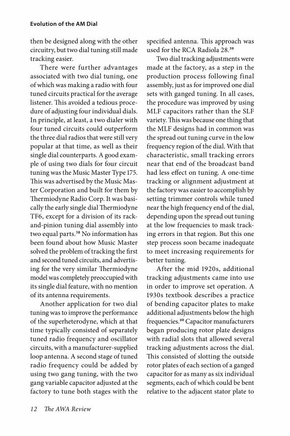
Fig. 1. An Ozarka, Inc., 1926 Viking Model 5-A, representative of the three dial radios produced by many companies in the mid 1920s period.1

2 The AWA Review
Evolution of the AM Dial
set, with dial numbers given as frequen-cies rather than the simple 0–100 scale that had been practically a tradition. This result was not a simple process, because it involved two largely sepa-rate development paths, with differing objectives followed by parts manufac-turers and by radio companies, and with both groups influenced by the buying public. These paths later con-verged, resulting in today’s familiar AM dial, but details of the convergence process have received little attention because of the way technology, style, and user interest interacted. The pro-cess is described here, first in terms of the developments and events that affected the parts manufacturers and the buying public, and then for the radio companies.
Variable Capacitors and Tuning the BandThe component of choice for chang-ing the frequency of a tuned circuit soon became the variable capacitor after the adoption of the expanded broadcast band. Capacitor manufac-turers included those producing them along with other products, and others specializing in variable capacitors. The situation was complicated by the fact that a few radio companies developed and produced their own, in some cases solely for themselves, while others also supplied home-builders and amateurs.
When broadcast radio as we know it today began in 1920, existing parts manufacturers simply continued to produce capacitors which had been previously used by almost everyone
except manufacturers of certain scien-tific instruments. The commonly used type can be categorized as straight line capacity [SLC], a rotary plate design with capacity proportional to plate rotation. There are also two other fundamental types, the straight line wavelength [SLW] with wavelength proportional to plate rotation, and the straight line frequency[SLF] with frequency proportional to plate rota-tion. The latter types were already well described in textbooks of that period, but they were rarely used.
Communications receivers cover-ing a wide range of frequencies usually had vernier tuning controls, because together with high selectivity there was a need to better separate stations on the dial. Use of vernier tuning was also an option from the beginning for the new broadcast radios that were suf-ficiently selective to separate closely spaced stations. Methods included a small variable capacitor in parallel with the SLC, a mechanical arrangement built into it or separately attached, or a mechanism in the tuning dial itself. Of course this resulted in a higher price for the total assembly, but it was not usually an excessive one.
The usefulness of vernier tuning became apparent to many listeners as more and more stations came on the air. This made them aware of a major disadvantage of the SLC: it crowded together the stations near the high fre-quency end of the dial. It also expanded the separation of frequencies near the low end of the dial, but of course there was no objection to that vernier effect.

Volume 28, 2015 3
Kinzie
In fact, a vernier control was a good solution for high frequencies crowding, and it became widely used during the first year or so following the expansion of the broadcast band in May of 1923.
A different solution of the crowded frequencies problem was introduced by the parts manufacturers about a year later, influenced by the fact that the market for sales to consumers building their own sets was more important than the one for radio manufacturers. This unusual condition is shown in Table I, abstracted from statistics gathered by historian Alan Douglas from early arti-cles2, and it was caused by manufactur-ing capacity that had not yet sufficiently expanded to meet consumer demand. As a result, by 1923 manufactured sets were outnumbered six to one by home-built products.
For sales to individuals, producers of variable capacitors at first concen-trated on two new designs, introducing an affordable version of the SLW, and shortly thereafter doing the same for the SLF. This activity was almost entirely separate from sales to radio companies, where there had been earlier interest in alternatives to the SLC. Possibly the first information to the general public that something besides the SLC was being
manufactured appeared in September 1924, in an article published in QST magazine.3 At that time, QST, the offi-cial publication of the American Radio Relay League, was readily available to the public as well as to its members, and appeared at newsstands along with other radio magazines.
The article described the three basic variable capacitor categories, and sug-gested that the SLF would eventually become the choice for broadcast radios. This was a reasonable suggestion at the time, but as will be seen it was not what actually happened. It also gave the impression that all three capacitor types were being manufactured, but there was no information about where to buy any alternative to the SLC. However, the same issue contained what may have been the first consumer-directed advertisement for a variable capacitor that explicitly called it an SLW. The announcement by Bremer-Tully Man-ufacturing Co. emphasized that the product was a laboratory-type capacitor at an affordable price.4 Essentially the same information had appeared earlier, but without the key term straight line wavelength, although an accompany-ing illustration showed rotor plates unlike those of the typical SLC.5 Earlier
Table I
Numbers of Radios Built in the Home Compared with Manufactured Sets2
Yearly Totals
1922 1923 1924 1925 1926 1927
Home-Built 1,000,000 1,500,000 1,750,000 1,000,000 750,000 300,000
Manufactured 100,000 250,000 1,500,000 2,000,000 1,750,000 1,350,000
4 The AWA Review
Evolution of the AM Dial
advertising by others also indicated a tuning characteristic that differed from straight line capacity, but without giv-ing details, and no one pointed out at first the important fact that an SLW improved the separation of the higher frequencies broadcast stations.
Bremer-Tully may have had little competition at first, but by March of 1925 General Radio Company was advertising its Type 247 variable capaci-tor as an SLW.6 Shortly afterwards in May, Phenix Radio Corporation of New York introduced its Ultra Low Loss Condenser as straight line frequency.7 However, the real rush of advertising during the Fall of 1925 was for the SLF, with such names as Karas Orthometric and AMSCO Allocating Condenser appearing.
The design of most variable capaci-tors entering the marketplace depended upon the property that capacity is pro-portional to the amount of rotor plate area in close proximity to the stator plates. Diagrams of plate shapes for this and the other two basic capaci-tor categories have been discussed in textbooks, and a typical illustration is shown here as Fig. 2, where the plate
shapes are those that were most com-monly used to produce the required plate area as the rotor shaft is turned.8 The plate shape designs for an SLC were almost always semicircular and with a centered shaft, but sometimes both of these differed for an SLW, and they varied widely for the SLF, an offset shaft being commonly used. One exception was the Phenix Radio Corp. design mentioned above, where the rotor plates were semicircular and with a centered shaft, as for an SLC. The stator plate outer diameter was also semicircular, but the plate surface was partially cut away from below to produce the SLF characteristic. The design had the same overall dimensions as a typical SLC, somewhat unusual for the straight line frequency type.
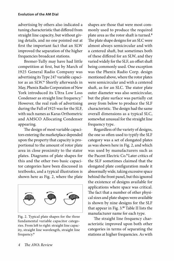
Regardless of the variety of designs, the one so often used to typify the SLF category was a set of elongated plates as was shown here in Fig. 2, and which was used by manufacturers such as the Pacent Electric Co.9 Later critics of the SLF sometimes claimed that the elongated plate configuration made it abnormally wide, taking excessive space behind the front panel, but this ignored the existence of designs available for applications where space was critical. The fact that a number of other physi-cal sizes and plate shapes were available is shown by nine designs for the SLF that appear in Fig. 3.10 Table II lists the manufacturer name for each type.
The straight line frequency char-acteristic improved upon both other categories in terms of separating the stations at higher frequencies. As with
Fig. 2. Typical plate shapes for the three fundamental variable capacitor catego-ries. From left to right: straight line capac-ity, straight line wavelength, straight line frequency.8
Volume 28, 2015 5
Kinzie
the SLW, there was some compression of the lower frequencies, but this was without crowding the stations together, although there were claims that such was the case. Straight line frequency tuning provided another feature that made it even more popular with the listening public: it equally separated the 10 kHz channels assigned to broadcast stations across the band. This made it very attractive to listeners, which in many instances enjoyed spending an entire evening searching for distant stations.
It seemed that the SLF could not be surpassed by further improvements, but new and different capacitors began to appear on the market, although with little fanfare at first, and with advertis-ing that in some cases revealed differ-ent tuning characteristics compared with the three fundamental catego-ries. An ad by Precise Manufacturing Corp. in October 1925 described its Precise Syncrodenser as a combina-tion of straight line frequency and straight line capacity, 11 referring to the high and low frequency regions
Fig. 3. Straight line frequency variable capacitor models from nine different manufacturers, each with a different plate design.10 Numbers refer to the manufacturers listed in Table II.
Table II
Companies that Manufactured the Straight Line Frequency Variable CapacitorsShown in Fig. 3.10
Manufacturer Number Company Name
1 The National Company
2 Gardiner & Hepburn, Inc.
3 Caldbeck Tool & Manufacturing Co.
4 Karas Electric Company
5 The Fett & Kimmel Company
6 Hammarlund Manufacturing Company, Inc.
7 The Hart & Hegeman Company
8 Bremer-Tully Manufacturing Company
9 Benjamin Electric Manufacturing Company

6 The AWA Review
Evolution of the AM Dial
of the dial, respectively. Two months later, the Allen D. Cardwell Manufac-turing Corporation described a Type C model giving semi-SLW tuning.12 Another company, General Instrument Corporation, advertised its Metralign Condenser in July 1926, describing its characteristics as “straight line tun-ing”.13 It was more specifically identified as the Metralign SLT in October, with reference to an earlier public announce-ment in May.14 Finally, in November it described the tuning characteristic as SLF at high frequencies, SLW in the middle frequencies, and SLC at the lows.15
The above examples are represen-tative of a type of variable capacitor that eventually became so important that it constituted a fourth unique category. Such a classification can be described as a hybrid or blend of two or even all three of the original types, and as such, it was destined to deter-mine the appearance of the scale for the AM dial. It became best known as the midline frequency capacitor or MLF 8, 16, and it was also called a cen-traline, with the term straight line tun-ing occasionally employed by General Instrument Corp.13 and in the text of some early articles, a misnomer not to be confused with the straight line frequency category.
Defining Midline FrequencyPossibly the first company to use the word midline was Hammarlund Manu-facturing Co. in September 1926 with full page advertising, and the tuning curve was defined by an illustration
comparing it with the three basic capacitor types.17 This is shown here in Fig. 4, where the Hammarlund Mid-line appears between the SLW and SLF characteristics, with all of these well below the straight line capacity curve. Features that were shared between Hammarlund and the other manufac-turers of the new category of capaci-tor were: 1. Low frequencies separation somewhat expanded, 2. High frequen-cies less separated than with the SLF.
There is some disagreement in the literature about what constitutes MLF tuning, and this includes restrictive definitions that ignore several brands of capacitors that were well known in 1926. It is useful for present purposes to describe the MLF as having tun-ing characteristics that are primar-ily between those of the SLC and the SLF. Note that this does not exclude a particular MLF curve from coinciding in part with the SLW, or which may
Fig. 4. A midline frequency curve for the Ham-marlund Mfg. Co. product, compared to the three fundamental variable capacitor types.17

Volume 28, 2015 7
Kinzie
include a combination of two or even all three characteristics in the manner in which the curve is shaped.
The Use of Advertising to Study Dial DevelopmentThe progressive appearance of four capacitor categories during a period from 1923 to 1927 is shown in Fig. 5, where advertisements and comments about capacitor models that were spe-cifically described in QST are plotted as quarterly totals for the 1923–1927 period. After 1923–1924 the relatively large numbers of entries for the SLC dropped as the other types entered the scene. Total advertising also dropped, and by mid-to-late 1927 it fell to nearly zero as the major innovations of single dial tuning and the AC power supply became all important. This sequence of events applies to the consumer mar-ket, but not to the wholesale market of radio manufacturing, which is dis-cussed below.
Linking advertising and other information to consum-ers (without specific linkage to radio companies) is sup-ported by results from studies of the Citizens Radio Call-book. One of the important features of the Callbook was a set of construction articles produced by staff members for each issue. Radio cir-cuits were chosen that were expected to attract radio enthusiasts building their own sets. These were con-structed and tested in the
company laboratory, highly detailed instructions were given, and lists of specific parts and their manufactur-ers were almost always included. The manufacturers were given the opportu-nity to advertise in the same issue, and they usually did. There were also ads and features typical of the other radio magazines of that time. It is evident that the construction articles would be particularly indicative of editor expec-tations about consumer interest.
Issues of the Callbook for the Fall of 1925 18 and for a similar period in 1926 19 show that interest in the SLW was already declining in 1925–1926, rising for the SLF, and just beginning in the case of the MLF. This is shown here in Table III, compiled from data in the Callbook issues. Timing is some-what different than for similar periods shown in Fig. 5, but the same trend is there, comparing one type to another, as is evident from the table.
Fig. 5. Quarterly totals for variable capacitor advertising and related commentary, from monthly issues of QST magazine, 1923–1927. Vertical scales give numbers of entries for each category.

8 The AWA Review
Evolution of the AM Dial
The MLF Characteristic—An Improve-ment, but Not for EveryoneRadio listener desire for improved tun-ing is a good explanation for the pro-gression from SLC to SLW to SLF, but it does not in itself explain the rise of the MLF, although there are sources that indicate that such was the case.8,16 While it is true that the typical MLF curve is linear, or nearly so, near the high fre-quency end of the dial, the change in frequency for a small amount of dial rotation is higher, compared to the SLF. This means that crowding of frequen-cies is greater, and is a step backwards in terms of the consumer viewpoint that existed during the earlier applica-tions of the first three categories.
One of the above sources that dis-cussed the applications of these vari-able capacitors left the backward step unexplained, instead contending that in comparison with the SLF, the MLF improved separation of the high pow-ered stations that were usually assigned to the low and middle frequencies.20
But decreased station interference as a property of the MLF itself seems to be an assumption that stations not suffi-ciently separated by receiver selectivity can somehow be separated by vernier tuning. This is simply not the case, as listeners with sets unable to separate stations learned from experience after installing vernier attachments.
By and large there is a lack of infor-mation to support claims that the MLF was the best consumer choice for broadcast radios. After all, from the radio listener’s viewpoint the SLF had solved the high frequencies crowding problem, and it spaced stations equally across the dial, making it easier to tune and log distant stations. Of course this describes listener attitude prior to 1926–1927, when spending the eve-ning searching for out-of-town sta-tions was often of as much interest as listening to the programs. Consumer acceptance changed in 1926–1927, after the introduction of capacitors with MLF characteristics, but it was
Table III
Variable Capacitors in Fall Issues of Citizens Radio Callbook*
Totals for variable capacitors identified in advertisements and text are shown except where noted.18’19
Year SLW SLF MLF Unspeci-fied**
Totals
1925 19 10 3 1 33
1926 7 15 6 0 28
* The SLC is not included here. (During that period it was generally assumed that a variable capacitor with no identification was of that type.)
** One entry described “straight line types” without clarification.
Volume 28, 2015 9
Kinzie
caused by change in listening habits rather than the availability of a new type of capacitor. Instead of searching for out-of-town stations during most of the evening, listeners were turning to local programming for entertainment. Nearby stations were easier to tune in, and signals were usually strong with no fading out in the middle of a program. There was no longer much attention given to how the dial was divided up, because tuning was easy and the MLF did that quite well.
The public became indifferent about the type of variable capacitors that were present in a newly purchased radio, but this was not the case for the radio companies. It will be shown below that midline frequency characteristics became their preference, and that was the reason for the rise of the MLF. It was an improvement over earlier types, but the improvement was for the radio manufacturer rather than the buying public. It had become unimportant to the consumer to return to some of the features that had been previously disliked.
Capacitor Development for Manufac-turer ApplicationsRadio companies and consumers shared a common interest in improved variable capacitors during the first few years of broadcasting, but the manufac-turers were sensitive to the expenses of radio production as well as to consumer concerns. Per unit cost of a capacitor and how it affected the manufacturing process were highly important. There is evidence that at least as early as the
period when SLW and SLF capacitors were first becoming available, a few radio companies were considering an omission of the path followed by the consumer market, and were going directly to MLF designs. While some followed up by developing their own versions, others used products designed for them by capacitor manufacturers. There were just a few that turned to the SLF along with consumers, evidently taking advantage of its rise to popu-larity. This minor trend did not last, because the entire industry soon agreed to a carefully defined set of character-istics for broadcast band capacitors.
The earliest example that was found illustrating these manufacturer activi-ties was that of A. H. Grebe and Co., where a radio engineer developed a capacitor intended for the forthcoming Grebe Syncrophase. It had a primar-ily SLF characteristic, but turned to SLC near the low frequency end of the dial.21 It is not clear whether it was actu-ally used in early production models, because all advertising which has been located that includes variable capacitor information refers to the straight line frequency type, and this began at least as early as Nov. 1924.22 Another com-pany that used the SLF was RCA, with its model 20 in 1925, 23 and with other models for that year.24 Grebe and RCA were among the few that produced sets with straight line frequency capacitors, and in the case of RCA it was for a very brief period.
As another example, Charles R. Leutz described the Silver Ghost model of his Universal Transoceanic Radio,

10 The AWA Review
Evolution of the AM Dial
developed in 1926 as using variable capacitors where
“The shape of the condenser plates is not straight line frequency or straight line wavelength. It is a very desirable combination of the two which provides the most satisfactory separation of wavelengths on the indicator drums.” 25
Both Grebe and Leutz (as Golden-Leutz, Inc.) developed MLF capaci-tors, but did not advertise them as parts available to the public. Another company, Silver-Marshall, Inc., sold parts as well as kits in the mid 1920s, and separately advertised SLW and SLF capacitors. It also developed its own design of a midline frequency capacitor, described as a compromise between the SLF and SLC.26 It appears that Silver-Marshall did not make it separately available, joining Grebe and Golden-Leutz in that respect.
It is understandable why capacitor manufacturer advertising for the MLF category was limited at first in radio magazines that were oriented toward consumers rather than radio com-panies. One company that did begin including it in its advertised line of products may have foreseen the possi-bility of extending its wholesale market for the product into the consumer field. This was the Allen D. Cardwell Manu-facturing Corp., which ran consumer advertisements for SLC capacitors dur-ing 1924 and 1925, and in that period also began indicating the existence of a variety of designs by including information such as “Cardwell now makes seventy-six different types—a condenser for every requirement”.27
Later advertising was still general-ized, but emphasized the adoption of Cardwell products by engineers and other professionals.28 Then in Decem-ber 1925 Cardwell announced to the public that it was offering the SLF.29 Also listed, along with several designs and adaptors, was the Type C, with the brief comment mentioned earlier that it gave semi-SLW tuning.
In April 1926 the Type C was again listed with the new description, and a new model, the Type E, was announced.31 The latter was described as SLF for the higher frequencies, and between SLF and SLW at the lower fre-quencies. This was in addition to cov-erage of Cardwell’s extremely unusual new “Taper Plate” design, where both rotor and stator plates were 1/8 inch thick at one end and tapered to a thin-ner cross section at the other. This was also available for the Type C.30,31
The progression of advertising in issue after issue of QST magazine, without including an explanation of characteristics, and associated bene-fits suggests that Cardwell was simply including capacitors already known to the engineering world in what was primarily an amateur/home-builder publication. Also, such advertising may have had an objective of targeting radio engineers that already favored that cat-egory and would recommend them to their company employers. More gener-ally, later Cardwell advertising in QST became increasingly directed toward licensed amateurs, 32-34 but still listed types C and E. However, in another publication an entry claimed that the

Volume 28, 2015 11
Kinzie
Type C was “almost the universal solu-tion of Radio Engineers and Editors” 35, additional evidence suggesting prior use in industrial activities. In this case, there was also some effort in that same ad to encourage consumers by referring to Type C use in a construction article intended for the listening public, and both Types C and E appeared in the following issue.36
Direct evidence of company interest in MLF type variable capacitors had appeared in the Fall of 1925, when DXL Radio Corp. ran a full page consumer ad for its SLF capacitor, but in a small inserted paragraph urged set manu-facturers to get price quotations on a different type.37 This was described as a Model S-S, with “Straight line fre-quency throughout lower 65 degrees on dial. Straight line wavelength through-out upper 35 degrees on dial. — Already standard with 21 set manufacturers.” As shown by these examples, it appears that manufacturer preference rather than consumer demand led to the mid-line frequency method of tuning. In order to discuss why this could have happened, in the face of SLF popularity with listeners, it is necessary to review the conditions that the radio companies faced during that period.
Manufacturer Methods of Meeting the Requirements for Ganged TuningRadios with two dials, and even just one dial, were replacing the three tun-ing controls on many broadcast sets being advertised as the change from the usual SLC was beginning. These early sets, especially the single dialers,
did not perform very well for those wanting to listen to anything other than nearby stations. Manufacturers hoping to compete with producers of existing models employing three tuned circuits, either made do with what they had while developing single dial con-trol, or took the interim step of produc-ing two dial sets. At least one dial of such sets tuned two or more variable capacitors, and these are discussed here as two dialers. Of course there were numerous radios with circuits using two individual tuning capacitors on the market which are not included here, just as the third dial on some sets was sometimes used for something other than tuning.
Dividing tuning between two dials made it easier to manufacture a receiver, because there were fewer prob-lems raised for producing a two dialer with capacitors that tracked together as the broadcast band was tuned. The most difficult problem was to build a radio that was not affected by the need to accommodate a wide variety of user-supplied antennas. A common solu-tion was to provide a separately tuned stage of radio frequency amplification at the input from the antenna, with the other tuned circuits controlled by the second dial. Adjusting the tuned circuits so that they tracked simultane-ously was easier with such an arrange-ment. A somewhat limited alternative was to produce a radio supplied with a loop antenna, not intended for use with any additional outside antenna or loop antenna substitute. Tuning for the first stage of amplification could
12 The AWA Review
Evolution of the AM Dial
then be designed along with the other circuitry, but two dial tuning still made tracking easier.
There were further advantages associated with two dial tuning, one of which was making a radio with four tuned circuits practical for the average listener. This avoided a tedious proce-dure of adjusting four individual dials. In principle, at least, a two dialer with four tuned circuits could outperform the three dial radios that were still very popular at that time, as well as their single dial counterparts. A good exam-ple of using two dials for four circuit tuning was the Music Master Type 175. This was advertised by the Music Mas-ter Corporation and built for them by Thermiodyne Radio Corp. It was basi-cally the early single dial Thermiodyne TF6, except for a division of its rack-and-pinion tuning dial assembly into two equal parts.38 No information has been found about how Music Master solved the problem of tracking the first and second tuned circuits, and advertis-ing for the very similar Thermiodyne model was completely preoccupied with its single dial feature, with no mention of its antenna requirements.
Another application for two dial tuning was to improve the performance of the superheterodyne, which at that time typically consisted of separately tuned radio frequency and oscillator circuits, with a manufacturer-supplied loop antenna. A second stage of tuned radio frequency could be added by using two gang tuning, with the two gang variable capacitor adjusted at the factory to tune both stages with the
specified antenna. This approach was used for the RCA Radiola 28.39
Two dial tracking adjustments were made at the factory, as a step in the production process following final assembly, just as for improved one dial sets with ganged tuning. In all cases, the procedure was improved by using MLF capacitors rather than the SLF variety. This was because one thing that the MLF designs had in common was the spread out tuning curve in the low frequency region of the dial. With that characteristic, small tracking errors near that end of the broadcast band had less effect on tuning. A one-time tracking or alignment adjustment at the factory was easier to accomplish by setting trimmer controls while tuned near the high frequency end of the dial, depending upon the spread out tuning at the low frequencies to mask track-ing errors in that region. But this one step process soon became inadequate to meet increasing requirements for better tuning.
After the mid 1920s, additional tracking adjustments came into use in order to improve set operation. A 1930s textbook describes a practice of bending capacitor plates to make additional adjustments below the high frequencies.40 Capacitor manufacturers began producing rotor plate designs with radial slots that allowed several tracking adjustments across the dial. This consisted of slotting the outside rotor plates of each section of a ganged capacitor for as many as six individual segments, each of which could be bent relative to the adjacent stator plate to

Volume 28, 2015 13
Kinzie
produce a small capacitance change in a given region on the dial. Adjust-ment of the radio frequency circuits for both tuned radio frequency (TRF) sets, and superheterodynes was done by first setting the dial at the high end and adjusting the trimmer capacitors for maximum signal level. Then the dial was rotated to bring the first radial segment of the rotor plates adjacent to corresponding stator plates; that seg-ment of each ganged capacitor section was then bent if necessary. Then the dial was rotated to repeat the operation for each set of the other segments.
In the early 1930s, TRF sets, and improved superheterodynes, both with several tuned circuits, were on the mar-ket. A textbook of that period discussed typical receivers and their alignment requirements, and gave an example of a set of alignment frequencies employed following the initial tracking procedure at the top of the dial.41 These were listed as 1120, 840, 700, 600, and 550 kHz. It is evident from the three low frequency numbers that even the MLF with its widely spaced low frequencies was no longer entirely sufficient to accommo-date the requirements of the improved generation of radios.
Radios with three and four TRF stages were common by 1930, and some had as many as five. Grigsby-Grunow Corporation’s models were noteworthy in that respect. Fig. 6 shows front and rear views of a Majestic Model 71B in a large console cabinet.42 Typical models in the 60, 70, and 80 series had four tuned circuits, and the Model 90s and 100s had five.43 A partial view of the
Majestic Model 90-B, and its five gang variable capacitor with a length of nearly 15 inches appears in Fig. 7.44 Text for that illustration described plates with four slots and hinge-type trimmer capacitors.
Fig. 6. Front and rear views of a Majestic Model 71B.42

14 The AWA Review
Evolution of the AM Dial
Industry Standards and ApplicationsMidline frequency tuning remained the choice of manufacturers during this period and for the years that fol-lowed, even though major changes in the radio industry took place during the Great Depression, beginning in 1929. The continuity of MLF design is reflected in the Radio Manufacturers Association (RMA) Standards, adopted and in place by the early 1930s. These defined tuning curves of the MLF type while being flexible in allowing for product design. However, there were some specific limits, including the maximum allowable capacity still present when a variable capacitor was positioned at the high end of the fre-quency band. This was an important consideration for the design of a radio dial, when taken together with other circuit capacitances that inevitably appear in parallel with it.
Using information from the Stan-dards as summarized in the Radio-tron Designer’s Handbook 45, a tuning
curve was developed and plotted as an example, and this included a trimmer capacitor for which RMA Standards information was also given. With band coverage just overlapping the early 1930s broadcast band, and including some additional parallel capacitance for the equivalent of circuitry effects, a graph of dial scale set point vs. fre-quency was developed. This is shown in Fig. 8, which is drawn in the form of a dial design that later became popu-lar. The typical MLF spreading of the low frequencies, and closer spreading of the high frequencies appear in the figure.
AM dials influenced by RMA Stan-dards met with little or no consumer resistance, which had already declined by the time that the MLF was widely employed. Any objections set builder enthusiasts may have had were over-shadowed by the fact that by 1927 buyers of manufactured radios outnumbered home-builders by four to one, as can be shown from the information in Table I. The upward trend in manufactured set sales was related to the fact that sets became easy to operate, largely due to
Fig. 7. A Majestic Model 90B five gang tuning capacitor with a length of nearly 15 inches, installed on the chassis.
Fig. 8. The nonlinear tuning scale resulting from employment of a variable capacitor based upon early RMA Standards. See text for discussion.

Volume 28, 2015 15
Kinzie
single control tuning, AC power, and the elimination of rheostats controlling filament voltages. The downward trend of home building continued in later years until it was mostly students and hobbyists that were constructing their own broadcast sets.
Radio manufacturers were the ones concerned with AM dial requirements. An example of the need for manufac-turer concern about details is apparent by close inspection of Fig. 8, where it is evident that the spacing of the last part of high frequency scale divisions is slightly greater than the spacing of the preceding pair. This was not always the case in practice, although it could arise as a result of the design of the capacitor frame and the plates, and also by the presence of a trimmer capacitor, the distributed capacitance of the parallel-connected tuning coil, and effects of other circuit components. Such features may vary from model to model, and they become increas-ingly important as the dial is advanced toward maximum frequency. Several minor differences in the spacing of dial scale graduations are possible, depending upon the contributions of the additional capacitances. The AM dials on the many receiver models that reached the marketplace demonstrate that condition. This affected produc-tion costs for the manufacturers that wanted to present a fully scaled dial, because revision was often needed when a new model was scheduled. Later on, overall appearance of the dial became more important than the scale itself for many table models.
The Growing emphasis on Style and Expanded ApplicationsRadios had most of the characteris-tics of modern sets by the late 1920s. Appearance had always played a role in encouraging sales, but was now becom-ing increasingly important, because few new innovations were becoming available to attract customer attention. One styling detail that would soon aid in defining a radio as an early 1930s model was already present in the form of a small size window dial showing just a portion of the scale. A few com-panies changed from the traditional external knob-and-dial assembly to small window dials while the three dialer was still popular, as shown by the Chelsea Truphonic Six in Fig. 9.46 The unobtrusive approach evident in the figure was followed by others through-out the entire period that the small window dial was used, but there were also many cases where an escutcheon was employed with the intention of emphasizing the window. These ranged from simple window frame designs to works of art, with one example of the emphatic approach appearing here
Fig. 9. An early application of the small win-dow dial, which appears in this Chelsea Radio Co. Truphonic Six advertised in 1926.46

16 The AWA Review
Evolution of the AM Dial
in Fig. 10.47 Some extreme designs mounted the escutcheon upon a large backing plate along with the other receiver controls, making the entire assembly the most important feature on an otherwise plain front panel. Although the small window origi-nated in the 1920s, it would be the early years of the following decade before it became one of the most important designs of that period.
Small windows were also associated with another type of dial that came into use during the later 1920s. This was the drum dial, which in one version attached directly to the shaft of a vari-able capacitor mounted directly behind the front panel, with the shaft parallel to the panel surface as shown by the example in Fig. 11.48 Here the drum dial is attached to the shaft of a three gang variable capacitor on the chassis of a 1927 RCA Radiola 16. Gearing hid-den below the dial makes the connec-tion to the shaft for the tuning knob, which appears below the dial. In later years it became customary to mount the ganged tuning capacitors at right angles to the panel, and the capacitor
shaft extended past gearing that con-nected to the drum dial, and through the panel for attachment of the tuning knob. In either case, the dial was visible through a small size window, as in the example of the Radiola 16, an external view of which appears in Fig. 12.49
One type of cabinet remained unchanged at first, following its arrival in the later 1920s period. This was the large console type that enclosed the radio chassis, the loudspeaker, and an AC power supply. What did change in appearance, starting in about 1929 and becoming widespread in 1930, was the cabinet for the table model radio, often to the form of the cathedral shape like the one in Fig. 13.50 Although there were already a few such models in 1929, practically the entire industry changed designs one year later. Harrison (1979) remarked about 1930 being the year of sudden cabinet changes, and added that he was unable to locate any single inno-vator of that phenomenon.51 The small window dial accompanied this change and remained in style for several years, although it shared its prominence with initial appearances of almost every
Fig. 10. A United States Radio and Television Corp. 1929 (unnumbered) Apex model, with a small window dial framed by an ornate eschucheon.47
Fig. 11. The RCA 1928 Radiola 16 chassis, with its drum dial on the shaft of the three gang variable capacitor. The shaft for the tuning knob extends forward from just below the dial.48

Volume 28, 2015 17
Kinzie
other type of dial that later came into general use.
By the 1931–1932 years, some varia-tions on the small window design had also appeared, and although they were not used as often as the basic design, some companies chose them for a number of their receiver models. These designs consisted of an expanded width, ranging from a short circular arc
to a full 180 degree display of the scale resulting in a half round window hav-ing a narrow radial dimension. Fig. 14 shows an Echophone 1932 cathedral with a slightly expanded small win-dow dial.52 Atwater Kent used small window dials in the early 1930s, along with expanded designs that included
Fig. 12. The Radiola 16, with its drum dial behind a prominent escutcheon. Eric Wenaas photo.49
Fig. 13. The Philco 20 cathedral model of 1930, its small window dial framed by a large escutcheon. SPARK Museum of Electrical Invention, Bellingham, WA.50
Fig. 14. An Echophone Model 5S of 1932, with a small window dial slightly expanded as a short arc. Robert Murray collection.52

18 The AWA Review
Evolution of the AM Dial
quarter and half round windows. An example is shown in Fig. 15.53
Early designs of most types of dials used in modern radios began to appear in the middle years of the 1930–1940 decade. These can be generally described as expanded view window dials allowing for a variety of shapes and sizes. One of the most important shapes was the round or airplane dial, which appeared at least as early as 1934, and it was much used in later years in both console and table model radios. Some of these were so large that they presented an impressive feature inde-pendent of cabinetry, even on the front of a large console. On a table model, such a dial was almost overwhelming. Fig. 16 shows a 1937 Zenith tombstone with its dial taking up nearly half of the cabinet’s vertical dimension.54
Easily read short wave bands were often included on these large dials.
There is evidence that the presence of an impressive dial had a positive effect upon radio sales. Zenith used its big black dial shown in Fig. 16 as an important aid for its mid-1930s sales programs. It was first publicized in the very expensive Zenith 1000Z Strato-sphere, a console model beyond the reach of the average buyer, but which generated a great deal of public interest. According to one source55
“The Stratosphere dial did not sell well to the public. It was more of an oddity—an object of wonder—and perhaps was used more effectively to promote the much lower priced, gen-eral Zenith line between 1936 and 1938. Starting with the 1936 Zenith black dial model line, Zenith sales vastly expanded from previous model lines.”
Fig. 16. A Zenith 1937 tombstone, with its large multiband black dial.54
Fig. 15. The Atwater-Kent Model 80 1931 cathedral, with a half round window dial.53

Volume 28, 2015 19
Kinzie
The appearance of the round win-dow dial in the middle of the decade was accompanied by such variations as ovals, large half round windows, and rounded edge rectangles. Squares and true rectangles were also used, and the latter rivaled the round window in terms of the number of models using it. In 1940s table model radios, very often there was a rectangular window with a simple semicircular scale behind it; alternatively the scale more or less followed one half of the window edge.
A different type of dial came into limited use in about 1935, and this was the slide rule dial that was shown diagrammatically in Fig. 4. In practice this was an elongated rectangular win-dow, with a pointer parallel to the short side that moved along the scale. This required a dial cord connection to the tuning knob, and some of the result-ing assemblies were quite elaborate. Springs, loops, bends, and pulley wheels sometimes made replacement of a bro-ken dial cord a frustrating operation for the serviceman. The name is based upon the most extreme version, where
the longer side of the rectangle is much greater than the shorter, as is shown in Fig. 17 on a typical table model.56 It was during the 1940s and later that the slide rule dial became really popu-lar. Expanded width windows were a good choice for multiband receivers, and they frequently appeared as alter-natives to round windows. There is no clear distinction between a wide slide rule dial and a rectangular dial in the many articles and publications describ-ing dial appearance.
Wood and Plastics for CabinetsWood cabinets were generally used for table models during the early years, and that type of construction remained important even when other materials came into use. Except for the large win-dow dial category with its dominat-ing presentation, the dial was a rather subdued addition to the front panel of a wood cabinet, and subservient to the presence of the cabinet as furniture. Consoles were impressive as furniture, and a well designed one made a beauti-ful addition to the living room. How-ever, by 1940 wood for table models was losing its predominance for use in inexpensive sets because of drastic changes in materials, and these pro-foundly affected all aspects of design and style in following years.
The use of wood for table models declined when it was established that the properties of plastics were often superior to wood for cabinets, as well as being less expensive as raw mate-rials. Molding was used to produce plastic cabinets, and once a mold was
Fig. 17. A Montgomery Ward & Co. Airline radio of 1950, with prominent slide rule dial.56

20 The AWA Review
Evolution of the AM Dial
designed and fabricated, large numbers of cabinets could be produced at low cost. As a result, only a few manufac-turers continued to use wood in their less expensive models, and there was often an effort to simulate a look associ-ated with plastic, such as streamlined shapes with brightly colored surfaces. Metal was sometimes used for midg-ets with the same intention, it being a revival of the briefly popular material of the late 1920 period. But these were minor exceptions, and plastic became the most important material for table model radios.
Highly detailed and contoured sur-faces could be produced with molded plastics, which permitted some rather intricate cabinet designs.57 An example appears in Fig. 18, where the numbers, with no scale as such, are an integral part of the design, and the knob is
another custom made component, very likely plastic.58 Designer knobs were almost always used, often with the company logo on the face. One exception was for some of the midg-ets, where knobs available from parts catalogs were used as another cost cut-ting measure.
Manufacturers began producing tens of thousands of small boxy sets with plastic cabinets, as usage of the material became widespread. These were intended for any room in the house, a type of application that has continued ever since. The radio that appears in Fig. 19 is an example, with wrap-around louvers characteristic of one of the ways plastic can be molded. It represents one of a number of differ-ent designs that appeared as a major market developed, for what became categorized as the second set. Cabinet shapes were produced that would have been simply too expensive for wood because of the extensive hand crafting that would be required. This included the flowing lines and highly rounded
Fig. 19. A two-color catalin cabinet for a 1946 Bendix Model 526C.59
Fig. 18. An Emerson 1952 model with intri-cately cast front that includes a numbers-only design in place of a scale.58

Volume 28, 2015 21
Kinzie
corners inspired by the then-current streamline-moderne architectural style.
Style became so important that some companies hired well known industrial designers to originate new cabinet designs, a tactic that suc-cessfully attracted customers.60 This emphasis on style produced a diver-gence from the accurately calibrated dial concept, in favor of conforming with cabinet appearance. Changes ranged from simple ones such as a minimum of art deco style numbers, to the extreme of eliminating the divided scale entirely, as was shown in Fig. 18. Just a few strategically placed num-bers in molded plastic gave a rough idea of where to look for a station. No doubt this was adequate for a set that was seldom tuned to more than one or two local signals. Pursuit of attractive appearance occasionally reached the point of eliminating the panel window altogether and reverting to a modern-ized version of the mid 1920s exposed knob and scale, with direct attach-ment to the variable capacitor shaft. This arrangement was usually found on small sets and midgets where low cost was important, and some of the models were quite attractive, such as the one shown in Fig. 18, with another example in Fig. 20,61 both with numbers molded directly into the cabinet face.
FM and Digital TuningFM stations came to more and more communities following World War II, and at first it was the advantage of high fidelity reception that was promoted. This was fully exploited by consoles with
well designed cabinet acoustics. The FM band also began to appear on many table model radios, even though most of the high fidelity feature was lost. It later became a virtual necessity on multiband dials. As the console radio in the living room was replaced by a TV set when television became all-important, stereo systems with multiband tuners became common. In fact, the AM dial, or at least a scale on a multiband dial remains a familiar sight today for a number of different applications, but its future may be affected by a trend that began in the late 1970s. That was when top-of-the-line portables and stereo equip-ment began appearing with digital or synthesized tuning.62, 63 Digital tuning was later used in relatively expensive equipment for many years, and there was a decrease in its cost during that period, so that now it has come into more general use. That manufactur-ing expense is no longer an important limitation has been demonstrated by the arrival of a tiny, handheld, AM-FM portable, with digital tuning and a rapid scanning feature. This radio, identified
Fig. 20. The tuning knob, and a numbers-only scale, on the front of this small size Motorola 1951 model.61
22 The AWA Review
Evolution of the AM Dial
only by a “Made in China” tag, recently appeared as a free promotional item for the purchase of mail order catalog goods. With manufacturing cost no longer a major limitation, it remains to be seen how much digital tuning will affect the employment of the AM dial for all types of applications.
References1. Douglas, Alan, Radio Manufacturers of
the 1920s, The Vestal Press, Ltd., Vestal, New York. Vol. 2, 1989, p. 220.
2. Ibid, Vol. 1,1988, p. xx.3. Mason, C. F., Some Suggestions to Vari-
able Condenser Manufacturers. QST, Vol. 8, No. 2, Sep. 1924, pp. 27–31.
4. Advertisement, Bremer-Tully Mfg. Co. QST, Vol. 8, No. 2, Sep. 1924, p. 73.
5. Advertisement, Bremer-Tully Mfg. Co. QST, Vol. 8, No. l,Aug. 1924, p. 63.
6. Advertisement, General Radio Co. QST, Vol. 9, No. 3, Mar. 1925, p.69.
7. Advertisement, Phenix Radio Corp. QST, Vol. 9, No. 5, May 1925, p.l; Radio News, May 1925 pg. 2041,
8. Ghirardi, Alfred A., Radio Physics Course, 2d. ed. Murray Hill Books, Inc., New York, 1932, pp. 545–547.
9. Advertisement, Pacent Electric Co., Inc. QST. Vol. 9, No. 10, Oct. 1925, p. 89.
10. Muhleman, M. L., Some Facts about Condensers. Radio News, Vol. 8, No. 7, Jan. 1927, p. 806.
11. Advertisement, Precise Mfg. Corp. QST, Vol. 9, No. 10, Oct. 1925, p. 88.
12. Advertisement, Allen D. Cardwell Mfg. Corp. QST, Vol. 9, No. 12, Dec. 1925, p. 83.
13. Advertisement, General Instrument Corp. QST, Vol. 10, No. 7, Jul. 1926, p.78.
14. Advertisement, General Instrument Corp. QST, Vol. 10, No. 10, Oct. 1926, p. 94.
15. Advertisement, General Instrument Corp. QST, Vol. 10, No. 11, Nov. 1926, p. 90.
16. Muhleman, M. L., op. cit, pp. 806–807.17. Advertisement, Hammarlund Mfg. Co.
Citizens Radio Callbook, Vol. 7, No. 2, Sep. 1926, p. 171.
18. Citizens Radio Callbook, Vol. 6, No. 2, Fall 1925.
19. Citizens Radio Callbook, Vol. 7, No. 2, Sep. 1926.
20. Ghirardi, Alfred A., op.cit, p.547.21. Batcher, R. R., The Design of the Grebe
Syncrophase. QST, Vol. 9, No. 4, Apr. 1925, pp. 13–15.
22. Advertisement, A. H. Grebe & Co., Inc. QST, Vol. 8, No. 4, Nov. 1924, p.4.
23. Wenaas, Eric P., Radiola: the Golden Age of RCA, 1919–1929. Sonoran Publish-ing Co., Chandler, Arizona, 2007, pp. 265–266.
24. Douglas, Alan, op. cit, Vol. 3,1991, p. 39.25. Leutz, Charles R., Modern Radio Recep-
tion, rev. ed. C. R. Leutz, Inc., New York, 1928, p. 135.
26. Silver, McMurdo, and Kendall Clough, Devising a Shielded Receiver Kit. QST, Vol. 10, No. 12, Dec. 1926, pp. 27–31.
27. Advertisement, Allen D. Cardwell Mfg. Corp. QST, Vol. 9, No. 3, Mar. 1925, p. 85.
28. Ibid., QST, Vol. 9, No. 10, Oct. 1925, p. 93.29. Ibid., QST, Vol. 9, No. 12, Dec. 1925, p. 83.30. Ibid., QST, Vol. 10, No. 2, Feb. 1926, p. 67.31. Ibid., QST, Vol. 10, No. 4, Apr. 1926, p. 63.32. Ibid., QST, Vol. 10, No. 7, Jul. 1926, p. 85.33. Ibid., QST, Vol. 10, No. 9, Sep. 1926, p. 65.34. Ibid., QST, Vol. 10, No. 12, Dec. 1926,
p. 95.
Volume 28, 2015 23
Kinzie
35. Advertisement, Allen D. Cardwell Mfg. Corp. Radio Broadcast, Vol. 10, No. 1, Nov. 1926, p. 75.
36. Ibid., Vol. 10, No. 2, Dec. 1926, p. 202.37. Advertisement, DXL Radio Corp. Citi-
zens Radio Callbook, Vol. 6, No. 2, Fall, 1925, p. 204.
38. Douglas, Alan, op. cit, Vol. 2, p. 197.39. Wenaas, Eric P., op. cit., pp. 268–269.40. Terman, Frederick Emmons, Radio Engi-
neering, 2d. ed. McGraw-Hill Book Co., Inc., New York, 1937, p.561.
41. Ghirardi, Alfred A., op. cit., p. 554.42. Douglas, Alan, op. cit., Vol. 2, p. 146.43. Gernsback, Hugo, Ed., Official Radio Ser-
vice Manual and Complete Directory of all Commercial Wiring Diagrams, 1930. Gernsback Publications, 1930; reprinted 1984 by The Vestal Press, Ltd., Vestal, New York, pp. 190–193.
44. Harrison, Arthur P., Jr., Single Control Tuning: An Analysis of an Innovation. Technology and Culture, Vol. 20, No. 2, Apr. 1979, p. 310.
45. Langford-Smith, F., Ed., Radiotron Designer’s Handbook, 4th ed., Wireless Press, 1952, pp. 1354–1355.
46. Citizens Radio Callbook, Vol. 7, No. 2, Sep. 1926, p. 180.
47. Douglas, Alan, op. cit, Vol. 1, p. 63.48. Wenaas, Eric P., op. cit, p. 291.49. Ibid., p.289, has a similar photo with
accompanying text.50. Photo courtesy of SPARK, Society for the
Preservation of Antique Radio Knowl-edge, Bellingham, WA, and Robert Murray.
51. Harrison, Arthur P., Jr., op. cit, pp. 319, 320.
52. Photo courtesy of Robert Murray.53. Courtesy of SPARK and Robert Murray.
54. Ibid., p. 167.55. Blankinship, Martin W., The 1000Z
Stratosphere: Zenith Radio Enters the Black Dial Era in Grand Form, 1933-1937. AWA Review, Vol. 23,2010, p. 66.
56. Bunis, Marty, and Sue Bunis, op.cit, p. 20.
57. Havranek, Barbara, The Bakelite Radio: an Icon of the 20 th Century. AWA Review, Vol. 14,2001, pp. 178–194.
58. Bunis, Marty, and Sue Bunis, op. cit, p.62.
59. Ibid., p.36.60. Havranek, Barbara, op. cit, pp. 182–184.61. Bunis, Marty, and Sue Bunis, op. cit.,
p. 100.62. Patton, Gerald R, Stay Tuned with Go-
Anywhere Hear-Anything Portables. Popular Mechanics, Vol. 148, No. 2, Aug. 1977, p. 76.
63. Fantel, Hans, New Devices Make Ste-reo Listening Easier than Ever. Popular Mechanics, Vol. 151, No. 3, Mar. 1979, p. 112.
AcknowledgementsMy thanks to Eric Wenaas for a photo of his Radiola 16, with the inset close-up of its tuning dial.
About the AuthorP. A. Kinzie graduated from the Uni-versity of Colorado in 1952 with a B.S. in Engineering Physics, followed by an M.S. in Engineering while working as an instrumentation engineer on ground tests of civil and military aircraft. This included structural strain measure-ments, measuring temperatures simu-lating extreme service conditions, and sonic fatigue investigations. He later

24 The AWA Review
Evolution of the AM Dial
became employed at the Rocketdyne Division of North American Avia-tion during the Apollo lunar landing program. There he contributed to the improvement of measurements of high heat flux by conductive heat transfer in rocket engines, using temperature measurement techniques, and he later wrote a book about thermocouples for temperature measurement, published by Wiley and Sons in 1973.
His interest in radio began many years earlier while in elementary school and continuing as an adult, leading to articles written about the subject as well as a book, titled Crystal Radio: History, Fundamentals, and Design, published by The Xtal Set Society in 1996. These activities, as well as crystal set experi-ments, raised questions about the com-ponents that were available or built at
home during the early days of radio, and pursing answers led to much of the background material for this article.
P. A. Kinzie

Volume 28, 2015 25
Radio Archeology, the Mt. Tam Wireless and a Call to Action
©2015 Bart LeeBarry McMullan, CHRS; Shane Joyce, an Irish archeologist; John Stuart, CHRS,
and I worked as a team on the archeology of Mt Tam, as will appear.
AbstractThe California Historical Radio Society (CHRS) has investigated and explored the site on Mt. Tamalpais, California of the long-lost Pacific Wireless Company station of 1906. It made this exploration as an exercise in Radio Archeology, complying with high standards of preservation, measurement and documentation. The 300-foot tall double-masted wireless station itself fell, not to the earthquake of 1906, but to crimi-nality, perhaps intended to frustrate the first wireless telegraphy circuit between San Francisco and Hawaii. Discovered artifacts lend a tangible dimension to technical studies of the unhappy history of the lost station. Historical research on the station sheds light on the technology of this early period in the history of radio itself.
Outstanding work in radio archeology at Clifden Ireland and at Marconi/RCA sites in Northern California provided the context for this exploration on Mt Tamalpais. These successes in documentation and preservation provide the model for future investigations worldwide. The Clifden site, lost to “the Troubles” in Ireland in 1919, has now been mapped and proposed as a tourist venue in the history of technology by the regional authorities. Archeologist Shane Joyce and historian Michael Gibbons have led this endeavor. The Maritime Radio Historical Society has explored and repurposed the California Marconi/RCA sites, showing the value of partnership (in this case with the National Park Service). Richard Dillman and a devoted crew have enabled this work, which includes regular radio transmissions in the old marine bands. Both sites, and earlier work by CHRS on the old KRE radio station in Berkeley, demonstrate the virtue of “adaptive reuse” as a mode of historical preservation, and as a way to establish centers for the study of the local history of technology.
This international work in tangible radio history, it is hoped, will stimulate others to go forth and do likewise in nearby regions. A literature and these models present approaches that can yield new and interesting information about the early days of radio. More and more opportunity for academic and professional engagement appears, and careful enthusiasts perhaps can pioneer this. Venues for publication abound.

26 The AWA Review
Radio Archeology: the Mt. Tam Wireless and a Call to Action
Fig. 1. The last tower falls at RCA’s Radio Central on Long Island, dynamited. This photo comes from RCA’s last Radio Central engineer, the late John M. (Marshall) Etter, W2ER, AWA (his photo).
Introduction to Radio ArcheologyThe Radio Corporation of America dynamited the radio towers at RCA’s Radio Central on Long Island 50 years ago, and abandoned one of the most important sites of modern technology. See Figures 1 and 2. RCA’s transatlan-tic circuits knit the world together, through war and peace, for five decades. Now there’s little left of them but a few stray nuts and bolts and old concrete work. This is all too often true of almost all of the early wireless telegraphy and radio stations that in their heyday stood tall and massive but are now often just concrete ruins if that.
We live in The Electrical Age, so we can ask: What is the science of its beginnings? That is, what is its arche-ology? Many say that we have enjoyed the cumulative benefit from Four Ages of Man:
1) The Stone Age – Fire and the First Tools, of which the stone tools have survived;
2) The Bronze Age – The First Use of Metals, for tools, art and money, a very useful triad;
3) The Iron Age – Strong Metals, leading eventually to the Use of Steam and the Railroad, the “Iron Horse”; 1 and now:
4) The Electrical Age – since the telegraph, 1833+-, we now enjoy elec-tronic communications and electrical power, “which makes all the difference in the world.”
In one of the more significant events in the history of technology, what we call “radio” freed communications from the long wires of the telegraph and the

Volume 28, 2015 27
Lee
later telephone. Tesla, Marconi, Braun, de Forest, in the 1890s and for twenty years thereafter, laid the groundwork for more than a century of exponential progress. People could now convey—signal—intelligence nearly instantly nearly anywhere.
“Radio” as a word, caught the popu-lar imagination at the beginning of the 20th Century: invisible waves (first of utility, then of entertainment and more) emanating like the newly discovered radiation of radium.
Early radio, “wireless telegraphy” as it was initially known, or just “wire-less”: 1) required stations, places from which to transmit and receive signals; and 2) radio stations required buildings to house equipment and antennas for signaling and receiving signals. Even the oldest of these buildings and anten-nas and equipment may still exist, or they may have left traces and remains. By investigating them, we can better understand them and the technology they created. Sometimes the growth
of modern society has overrun the old sites, but sometimes, especially near wild coasts, much remains to tell some stories of past industry, ambition and in retrospect, even grandeur. Wireless telegraphy may have needed wire only for its antennas and equipment, but it needed massive amounts of electrical power and rail and road access. This infrastructure also leaves traces that can illuminate the old sites.
Investigation of old radio stations and the like is a species of industrial archaeology; according to archeologist Robert A. Clouse:
“Industrial Archaeology is the recording, study, interpretation and preservation of the physical remains of industrially related artifacts, sites and systems within their social and historical contexts. ***
“The study of Industrial Archaeol-ogy adds to our understanding of this significant change in the human con-dition by
[1] adding a tangible dimension to technical studies, by
[2] providing technical information on obsolete processes not obtainable from other sources, and by
[3] supplying useful reference points of economic growth and social change.
“A research focus on change reflected in production systems, trans-portation systems, and communities will enhance our knowledge of the complex relationships that link cultural elements and on an understanding of the mechanisms that produce change in those relationships.”2 [Emphasis added].
Fig. 2. A nut and bolt from the last tower at RCA Radio Central, salvaged by Marshall Etter and sent to the Museum of the Cali-fornia Historical Radio Society.

28 The AWA Review
Radio Archeology: the Mt. Tam Wireless and a Call to Action
In any such investigation by ama-teurs, we are subject to a Prime Direc-tive: Take Nothing but Pictures; Leave Nothing but Footprints. With, however, appropriate permissions and trained personnel, artifacts can be salvaged and documented for museums or a landowner or an agency. Responsible archeologists will always seek out and work with the appropriate authorities or private landowners. They are usu-ally happy to help, often as a matter of pride or duty. “Digging” should be left to professional archeologists with permits and good counsel, because the applicable laws are strict, often penal, and complex.
Radio Archeology Today— Part One, Clifden, IrelandArcheologists, in particular Shane Joyce and Michael Gibbons, have recently explored and mapped the ruins of the Clifden, Ireland Marconi site, on Ire-land’s West coast. See Figure 3, their map of the site’s 1915 configuration. This work has made for one of the out-standing achievements of radio arche-ology, and provides a model for future work worldwide. Joyce and colleagues such as Gibbons have interested the local authorities in the significance of the cultural and technological history of which the site is emblematic, and fos-tered a preservation and interpretation campaign. Please see the sidebar for an appreciation of the site and their work, published as the “Marconi Project” by the Irish Tourism Board, 2014; this publication presents a wealth of pho-tographs of interest to radio historians.
Images give some sense of the Clifden ruins. At Clifden today, a remaining stairway goes—now—nowhere (Fig. 4). Sheep graze where there were once signals. But consid-erable literature and archival materi-als bless the archeological endeavor. Generally, for turn-of-the-19th-Cen-tury sites, legal records about land and sometimes litigation and local histories (and sometimes even about warfare), can focus the archeological endeavor. At Clifden, the Marconi company built its own powerhouse, peat as fuel being plentiful. It connected its inter-nal rail system to existing rail. Investi-gators have located the remains of both of these kinds of infrastructure. The presence of traces or remains of such infrastructure suggests a major site of some sort, even in the absence of other information.
The local population at Clifden also celebrates its Marconi connection and Marconi’s Irish ancestry. (It is said that “Real Radio Historians drink Jameson’s Irish Whiskey.” Such imbibing honors Marconi’s Irish mother, Annie Jame-son, who believed in him and intro-duced him to the family whiskey and grain fortune in England, enabling an initial capitalization of £50,000, well over $6,000,000 in today’s money.) The peat bogs provide easy access to the site, albeit with some risk of drowning and joining the prehistoric “bogmen.” But close to the bog-traversing trails themselves, bits of history lay about (see Fig. 5). The town of Clifden maintains interpretive displays about the Marconi site. Radio archeology at Clifden fosters

Volume 28, 2015 29
Lee
Fig. 3. The Clifden, Ireland Marconi station as of 1915 mapped recently by Irish archeologist Shane Joyce and historian Michael Gibbons.
Fig. 4. A well-preserved Clifden Marconi site stairway to nowhere, now, nonetheless invites a casual climb, but once it led to a nice building deserving a nice set of stairs (Bart Lee photo, 2007).

30 The AWA Review
Radio Archeology: the Mt. Tam Wireless and a Call to Action
“Radio Archeology” by Bart Lee[Clifden, Marconi and the New World of Technology]
—As published by the Irish Tourism Board, 2014—
“Interesting places call out to visitors. For those interested in how our modern technology of communications evolved, a wireless telegraphy site like Clifden has tales to tell, both technical and social.
“And in Clifden’s case its Atlantic set-ting in North West Ireland, and the com-fortable village of Clifden itself, provide bonuses to the visitor.
“The telegraph itself appeared in Europe and the United States in the decades of the 1830s and 1840s. Cables across the Atlantic followed, as did their monop-oly pricing on vital commercial com-munications. Can it be done without wires, asked Marconi. Can we talk to ships at sea? He showed it all to be pos-sible. His Irish Jameson family connec-tions financed his London company. In 1901 he signaled across the Atlantic. A reliable circuit across this ocean would both repay his investors and vindicate his vision. It would take two initial sites for the industrial -scale wireless plants.
“Marconi, in 1907, selected a lake site just West of the village of Clifden, with ample water supply, wet ground and ample acreage for antennas. Hundreds of thousands of watts of power hurled his messages across the Atlantic.
“Communications has moved on to radio, television, satellites, fiber optics and the Internet, but Clifden is an anchor point in that development. Yet it is now a ruin, fallen prey to time and the Trou-bles. Ruins, however, talk to us. A visit to Marconi’s Clifden site shows the scale of the vision, and some of the roots of today’s world. A walk of the remains of the plant shows the immensity of the commitment Marconi and the people of Clifden made to its success.
“So many technical arts predominate in the world today, and many people with technical interests like to visit places important to technology. They are, in a sense, technology tourists. Clifden should be on every such itinerary. It is one of the premier archeo-radio sites of the world, along with the Swedish radio station SAQ, Marconi’s Poldhu, Corn-wall site, and the California Marconi/RCA site radio station KPH. The village of Clifden makes it one of the most invit-ing of such sites.
—Bart Lee is one of the foremost author-ities on Radio History in the USA. He attended the 2007 Centenary event at Clifden. His ancestors hail from Letter-mullin [Galway].”3

Volume 28, 2015 31
Lee
adaptive reuse by way of interpretation a century later of a significant tech-nological event. Two of its goals are to encourage visits to Clifden and to encourage construction of facilities for visitors to the Marconi site.
Radio Archeology Today— Part Two: Marconi and RCA Northern California sites including KPHRichard Dillman, W6AWO and his col-leagues at the Marine Radio Historical Society (MRHS)4 have resurrected the historic Marconi/RCA operations in Northern California (Bolinas). They have adapted the facilities as found to a related reuse as an era-correct radio station in the historical marine radio service. They work with and on behalf of the National Park Service (NPS), as enlisted volunteers. NPS goals include optimal “cultural resources manage-ment.” Adaptive reuse is a tenet of cultural resources management. The alternatives are often waste, disuse and the loss of important sites and related knowledge.
Moreover MRHS has researched and documented the origins of the leg-endary and related West Coast United Wireless maritime radio station KPH, from its start in San Francisco’s Palace Hotel (hence “PH”), to San Francisco’s Russian Hill, to its culmination North of Bolinas at Pt. Reyes as part of Ameri-can Marconi. The enthusiasm of MRHS has unearthed old ephemera, for exam-ple, two images of PH in 1908, sited on Russian Hill (Figs. 6 and 7 nearby).
Fig. 5. The Irish civil war circa 1919 destroyed the Clifden Marconi station. Bits and pieces remain on the ground awaiting conserva-tion—here some glass and bolts (CHRS Museum collection, Bart Lee photo).
Fig. 6. Station PH atop Russian Hill, San Fran-cisco, in a 1908 postcard image (Maritime Radio Historical Society image).
Fig. 7. Station PH atop Russian Hill, San Fran-cisco, photographed by then- Massie company operator Arthur A. Isbell circa 1908. (Photo from the Isbell Archives collection of Rachel Isbell Branch, used by permission, © Rachel Isbell Branch & Bart Lee, 2011).

32 The AWA Review
Radio Archeology: the Mt. Tam Wireless and a Call to Action
Complaints about the spark transmit-ter’s noise caused the company to move the station to then bucolic South San Francisco in 1912.The maritime, finan-cial and industrial affairs of the West centered in San Francisco at the time.
From what is now Daly City, KPH (Fig. 8) worked ships on the coast and on the high seas, and as far away as Japan. American Marconi developed the transpacific station at Bolinas, North of San Francisco, under the direction of Marconi Engineer Arthur A. Isbell starting about 1914. Then KPH joined its larger cousin in 1919 first at
the Marshall receiving site then at the nearby Pt. Reyes receiving site (after World War Two).
The Bolinas station originally ran about between 230 and 280 Kilowatts (KW) of spark, and was known as the “Rock Crusher.” American Marconi ran special electrical power lines into Boli-nas taking advantage of California’s just recently developed hydropower. More-over, a nearby rail connection facilitated shipping of massive equipment, and eventually rail ran into the site.
In the early 1920s, RCA as successor to American Marconi, used Alexan-derson alternators as KET. One such alternator survives (and operates) at the Swedish museum station SAQ. In those days all radio was “long wave,” low frequency generally below one Megahertz, 300 meters wavelength. The main marine frequency was 500 KHz, 600 meters. The Bolinas alterna-tors operated at 23 KHz, 13,000 meters wavelength at 200KW and was known as Bolinas High Power. Then, after the 1920s, came Bolinas’s great days of vacuum tube short wave transmitters and 24 Pacific international circuits, until its end in the late 1960s.
The MRHS operates weekly on maritime frequencies as KSM (courtesy of Globe Wireless) and amateur radio frequencies as K6KPH. This is an out-standing example of “adaptive reuse,” a prime goal of NPS cultural resources management. KSM’s maritime Morse code signals reach as far as the coast of Vietnam with good propagation.5
Two MRHS principals (Mike Johnson and Richard Dillman) have
Fig. 8. Station KPH about 1912 in what is now Daly City (“top of the hill”), California, looking North West out to Lake Merced and the Pacific Ocean. A second tower is behind the camera. Large ground screens made the station an effective marine band (600 meters) radiator and receiver, according to Richard Johnstone, a pre-WWI operator there.

Volume 28, 2015 33
Lee
explored the Daly City KPH site South of San Francisco and the Marshall receiving site, North of Bolinas. This sort of exploration provides a present-day factual basis for the stories that many documents still tell about this legendary radio station; “adding a tangible dimension to technical stud-ies.” In this case it helps link American Marconi’s maritime service with its transpacific circuits. By careful atten-tion to the geographical clues in the 1912 ± old photo (nearby), they located the KPH site of 1912. There they found and photographed, and published,6 the foundations of the original “shack.’ (See Fig. 9).
Richard Dillman also found inter-esting some odd antenna patterns at
Marshall, on the East shore of Tomales Bay. That old receiving site is now the Marconi Cove State Conference Center, and partially conserved. (Until recently there were still bits of hardware lying in the grass in the nearby hills, rusting (see Fig. 10). The wireless operators’ hotel, which they called “The Hotel de Gink,”7 still stands. Marconi built such hotels at perhaps all of its sites world-wide, on the same plan. The old antenna
Fig. 9. KPH a century later. MRHS principals Mike Johnson and Richard Dillman found and explored the 1912 site in 2012. Here Mike Johnson stands amid the foundations for the 1912 station (Richard Dillman photo).
Fig. 10. Nuts salvaged in the early 1990s from a field near the Marconi/RCA Marshall receiv-ing site, near a surviving concrete antenna stanchion (CHRS Museum collection, Bart Lee photo).

34 The AWA Review
Radio Archeology: the Mt. Tam Wireless and a Call to Action
field is just a hike up the hill. It seemed like an antenna ran crosswise to the proper direction for receiving from the Pacific. About the possible cross-wise antenna, Richard Dillman sent out an inquiry. Marconi engineer Elmer T. Bucher’s 1917 wireless book solved the mystery: it was indeed a perpendicular antenna.
This was standard in the Marconi sites, starting with Clifden, to balance out (to null) the associated transmitter radio energy (see Bucher’s illustration based on Clifden and its receiving site at nearby Letterfrack, Fig 11). With-out such nulling of the Rock Crusher,
receiving would have been very chal-lenging indeed. While a big transmit-ter site may be easy to find, locating its equally important companion and smaller receiving site poses challenges. Such sites generally needed little power and no rail, and only a telegraph line to connect to overall circuit management. Yet each circuit required reception, and these sites had to be “nearby” for effec-tive coordination and supervision. Thus reference to documentation can help interpret physical findings, and physical findings can shed light on ambiguous documentation. Dillman’s find of the traces of the crosswise antenna, and the
Fig. 11. Marconi Engineer Elmer T. Bucher’s explanation of the “cross-wise” balancing anten-nas at Marconi installations (proposed by H.J. Round). Bucher uses the Irish stations as his example. It was the remains of such a balancing antenna that Richard Dillman recently discovered at Marshall.

Volume 28, 2015 35
Lee
documentation, shows that a receiving site not only had to be some distance from a big transmitter to copy weak and distant signals, but also that the opera-tion had to protect reception technically.
A photo shows one of the Marshall receiving tower bases, with MRHS principal Paul Shinn’s Transoceanic happily ensconced on top of it (another adaptive reuse), listening to the Pacific as did the Marshall site for so many years (Fig. 12).
Bengt Svensson, SMØUGV is a principal of the Swedish Alexander-son alternator station historical (and working) SAQ and an active Antique Wireless Association member. SAQ as a museum station is itself a triumph of
adaptive reuse. On a recent visit to Boli-nas, he identified a concrete structure as part of the station KET alternator antenna system. Bengt is pointing out the rods at the base of this inductor support in Fig. 13; the identical inductor support may be seen in service at SAQ, Fig. 14. A Riggers’ Shack, looking like a small cabin, is also preserved at Bolinas. Engineers hoisted it up the towers to work on the antennas (Fig 15).
Amateurs who are radio history enthusiasts have effected both the Clifden and the Northern California archeological endeavors. Public sup-port for preservation, adaptive reuse and related historical interpretation has followed.
Fig. 12. In honor of annual Marconi Day, Paul Shinn (MRHS) put a Marshall receiving antenna tower stanchion to adaptive reuse as a base for his Zenith Transoceanic short wave radio (his photo). Tomales Bay and the Pacific Ocean provide the backdrop.
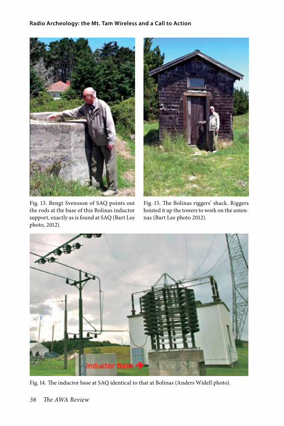
36 The AWA Review
Radio Archeology: the Mt. Tam Wireless and a Call to Action
Fig. 13. Bengt Svensson of SAQ points out the rods at the base of this Bolinas inductor support, exactly as is found at SAQ (Bart Lee photo, 2012).
Fig. 14. The inductor base at SAQ identical to that at Bolinas (Anders Widell photo).
Fig. 15. The Bolinas riggers’ shack. Riggers hoisted it up the towers to work on the anten-nas (Bart Lee photo 2012).

Volume 28, 2015 37
Lee
Tools and Techniques: GOOGLE® Earth, a new tool, and some other tools of the archeologists’ tradeThe new ability to see almost any-where on Earth provides the histo-rian and archeologist a bird’s eye view of any interesting site.8 There are, of course, many sources for site research including:
1) People: (A) who were there; (B) who knew people who were there; (C) who are familiar with the topic; (D) who have themselves researched the topic.
2) Archives: (A) personal; (B) fam-ily; (C) company; (D) interest groups (e.g., clubs); (E) institutions (e.g., muse-ums); government (e.g., NPS, NSA, Smithsonian); (F) commercial (e.g., Corbis (Bettmann Archive) for photos).
3) Publications: (A) books (i) old and (ii) new; (B) magazines and peri-odicals (i) old and (ii) new; (C) news-papers (mostly old); (D) ephemera (e.g., post cards, QSL cards).
4) But beware of the Internet with its 945,000,000 Google hits for Radio History—so doubt freely! On the other hand the premier sites contain an aston-ishing amount of useful information.
In addition to Corbis, commercial sources for images may provide view-able images with useful clues.9 But gen-erally the most interesting images come from period publications.
After site selection, Google Earth is very useful in planning an investiga-tion, especially because roads, rail lines and power rights of way may appear although they may not be apparent from the surface. Google Earth enables
site discovery as well as assessment. It also permits quick study of known sites, such as Marconi’s operations in Pol-dhu, Cornwall, UK and SAQ in Sweden, and comparisons. Dedicated historians and enthusiasts have conserved both of these sites, preserving their visibility even from the sky.
The utility of Google Earth for site discovery is illustrated by station NCZ on Hog Island, Virginia. An old Department of Commerce 1919 call-book lists a radio navigation beacon on Hog Island. The list gives its latitude and longitude: 37° 22΄ 36˝ North by 75° 42΄ 37˝ West. Plug this data into the program, and up pops a satellite view of Hog Island and a pin for the station coordinates (Fig. 16). Swooping around on the island, a ruin appears, as does a radio tower (Fig. 17).
Thus from old data and a new way of seeing it, a potential radio archeology site is available for exploration. So, too, known sites may be studied by way of associated photographs; for example, Marconi’s site at Poldhu in Cornwall (Fig. 18).
Good exploration, especially sur-face exploration, is well documented, measured and photographed. The “tools of the trade” include maps, GPS, mark-ers, measurers (rods and tapes), still and video cameras (see e.g., Fig. 19), inclinometers, altimeters, surveying instruments and notebooks including forms for recording data. Smaller tools such as centimeter sticks and calipers will also come in handy for measuring artifacts in place.
The deep archeologists of, say, the

38 The AWA Review
Radio Archeology: the Mt. Tam Wireless and a Call to Action
Fig. 17. A closer look at NCZ’s location shows ruins and a radio (?) tower, per Google Earth®.
Fig. 16. Google Earth ® shows a spit of land, a good place for a radio compass station, and the coordinates of the old NCZ station (Google may well be more precise than the old coordinates, which are just a little offshore).

Volume 28, 2015 39
Lee
ancient world’s remains, also use shov-els, trowels and the like. These tools10 are best left to the professionals with permissions to dig.
High Crime on Mount TamalpaisThe California Historical Radio Society (CHRS), like almost everything else in Northern California, looks up to Mt. Tam, just North of San Francisco in Marin County. The sharp-eyed can see a Radar dome on its West peak. But once there was more: a world class wireless station in 1906, according to old recollections supported by some ephemera. The 1906 postcard (in Fig. 20) shows its high towers and many guy lines. The bulldozers, however, have had their way on the Middle and West peaks of Mt. Tam. Little trace of what may have been on top 110 years ago remains.
The Pacific Wireless Company had enjoyed great success with the first
Fig. 19. Some tools of the trade: meter sticks (and meter tape measure), North Arrow (cms), photographed signs; a GPS enabled camera will record the exact location, here φ 37° 55 , λ -122° 1 . This is the South end of a shielded coax Large Aperture Vertical Loop Antenna, oriented North and South for reception of SAQ; it measures 33 meters by 2 ± meters. Note the double pulley at the base of the North Arrow stick.
Fig. 18. A Google Earth® image of a posted (pinned) photograph by David Matthews, G3ZZP of Marconi’s Poldhu site, annotated.

40 The AWA Review
Radio Archeology: the Mt. Tam Wireless and a Call to Action
commercial wireless telegraphy cir-cuit between Catalina Island and Los Angeles’s port San Pedro in 1902. The company principals saw that a Hawaii and San Francisco circuit (2,400 miles) would be lucrative, undercutting the monopoly cable rates. Marconi had gotten across the Atlantic in 1901, a comparable over-water distance. Fes-senden sought to establish a circuit to Scotland. The times and technology were right for a try.
The spark-gap that generated radio frequency energy pushed the state of the art. The induction coil for the Hawaii circuit looks to be almost four meters in length, perhaps a little longer. (Fig. 21; it is reported to have been 15 feet long). Some 2,000 miles of No. 30
Fig. 20. A commercial postcard circa 1906 showing the wireless station and towers on the Middle Peak of Mt. Tam, looking East to East Peak (author’s collection). The old monochrome photographs on which this and another color post card are based do not show guy lines, but the post cards do, perhaps sim-ply courtesy of the colorist. Pacific Wireless leased the land August 1, 1905 for 15 years, as a 1,200-foot diameter circular leasehold, according to newspaper reports.
Fig. 21. The induction coil (“helix”) for the Mt. Tam station, labeled on the photograph “Honolulu or Bust”; supervisor A.F. Krenke at left. Photo from the CHRS Society of Wireless Pioneers archive. The original caption reads: “PW technicians winding a helix coil for the Mt. Tamalpais station, Mr. Krenke at far left. Cloth stacked in corner was applied over each layer of wire and coated with shellac. Process was not unlike that used for making today’s surfboards with fiberglass.”

Volume 28, 2015 41
Lee
silk covered wires enabled the four ton coil to make a spark 15 feet long at half a million volts.11 The crew included the experienced A.F. Krenke as a super-visor, who had worked the Catalina Island circuit (Figs. 22 and 23).
A 1905 Los Angeles newspaper story provides some background on Pacific Wireless.12 Pacific projected the cost of the Mt. Tam station at $100,000 in 1905 ($2½ million or more today). Retired General A.L. New acted as the general manager for Pacific. New claimed that Pacific competed with landline tele-graph companies between Seattle and Victoria, B.C., undercutting telegram prices by 32%. Pacific claimed to be looking to transpacific circuits into the Orient.
In mid 1906, the Oakland Tribune reported on the construction of the Mt. Tam station.13 Engineer George Ross in Oakland supervised the construction of the two 300 foot triangular towers of Oregon Fir. Sixty tons of Fir, 40,000 feet of it, went into the towers. The com-pany hoped that the towers’ elevation on Mt. Tam of 2,000 feet would help overcome the curvature of the earth “in a measure.” (Each tower was to be stabilized with 44 cables).
For receiving, the company pro-posed to use a simple passive detector: “… a needle lightly touching a carbon disk.”14 In 1905–’06, the filings coherer, very insensitive, was the usual detec-tor—carbon and steel was very sensi-tive in comparison.15 Marconi ships used the proprietary magnetic detec-tor, and Fessenden and de Forest used patented electrolytic detectors. The
“crystal detectors” had not yet been invented by 1905. General Dunwoody invented the carborundum detector in 1906. G. W. Pickard invented the silicon detector the same year. Neither was in general use in 1906. The vacuum tube was just a gleam in Lee de Forest’s eye. KPH, using galena crystal as its detector, sometimes logged transpacific transmissions.
The Mt. Tam station preferred its type of detector, from which traffic could be copied by ear (rather than inker). It hoped for high rates of data transmission, up to 40 words a minute16 (versus maybe ten for an inker). Lee deForest’s wireless system also relied on crack operators copying by ear, from his electrolytic detector (modeled on if not stolen from Fessenden’s).
Popular Mechanics magazine fea-tured the Mt. Tam wireless station in an article in March 1906.17 Further national publicity ensued from an article in Technical World Magazine in June 1906.18
The station’s fan antenna (cf. Fig. 27 —a fan of many 175-foot long copper wires, weighing 3,000 pounds) appears to have been modeled on Marconi’s jury-rigged fan antenna at Poldhu in 1901, used after the inverted cone, intended for the transatlantic test, blew down in a storm. Others of the era also used fan antennas and may have believed them to be directional. At the low frequencies generally used (except by de Forest) the fan would have acted as a capacity hat to bring the lead into resonance.
At this remove, we cannot know if a storm of the century or maybe sabotage

42 The AWA Review
Radio Archeology: the Mt. Tam Wireless and a Call to Action
Fig. 22. The Pacific Wireless Company Mt. Tam crew in 1906, supervisor A.F. Krenke third from left with pipe and annotation above. Photo from the CHRS Society of Wireless Pioneers archive.
Fig. 23. A.F. Krenke operating the Catalina circuit in 1903 from station “G” located at Seventh and Alameda Streets, Los Angeles. Photo from the CHRS Society of Wireless Pioneers archive.

Volume 28, 2015 43
Lee
destroyed the station. (Arthur A. Isbell pioneered the Honolulu circuit by spark a couple of years later. Federal com-mercialized that circuit with its arc transmitters around 1910.)
The 1906 station’s signals never reached Hawaii, its intended circuit—but not because of the 1906 earthquake that devastated San Francisco. Haraden Pratt, 60 years ago, advised Presidents Truman and Eisenhower on commu-nication policy. In his Reminiscences he wrote about the sabotage of the twin towers of the Mt. Tam Station, in December 1906 when he was a boy:
“I could see the towers from the kitchen window and, noticing that they were gone, climbed up there with my father and was surprised to see that some guy anchor rods had been cut with a hacksaw.”19
After a big storm in December 1906, only ruins were left of the Mt. Tam sta-tion. The hopes of the nascent Pacific Wireless Company died in those ruins.20 So, “who dun it?” A century later it’s hard to say, but there are suspects.
In the first decade of the Twentieth Century, the United Wireless Telegraph Company dominated radio-telegraphy on the West Coast. (Marconi worked the East Coast). By December 1906, somebody had cut the guy anchors for the Mt. Tam station of Pacific Wire-less, according to Pratt, and down it came. In 1907, somebody took a shot at the Massie company’s newly arrived Arthur A. Isbell as soon as he came to San Francisco. “They tried to kill me” Isbell noted at the time, and he
photographed the bullet hole and his shattered shaving mirror. “Liars, Cut Throats and Thieves” Isbell called them, after he had tried to establish the Massie company’s West Coast station for mari-time traffic at San Francisco’s Land’s End in 1907. Then in 1908, somebody cut down the DeForest company’s San Francisco antenna mast with which he hoped to communicate with his wire-less telephones on the visiting Great White Fleet. “Three strikes and you’re out”?
The United principals went to prison not for these criminal acts, but for stock fraud. Marconi absorbed the United stations, assets and personnel after United’s bankruptcy in 1911. Isbell noted that a United Wireless princi-pal died in prison (United President C.C. Wilson did so in Atlanta, 1912). Isbell, after American Marconi, later went to work for David Sarnoff at RCA, its successor as of 1919, as did Elmer Cunningham, Clarence Tuska, Howard Armstrong, Elmo Pickerel and other wireless pioneers.
Fifty years after 1906, a newspaper reporter went up Mt. Tam to take a look:
“Fifty years ago, the ‘most power-ful wireless station ever built’ stood on the middle peak of Mt. Tamalpais. Its towering masts blew down and were destroyed on the night of Dec. 10, 1906. The station has vanished from memory almost as completely as it has disap-peared from the mountain.
“Curious visitors to the middle peak today, poking around in the under-brush, will find all that remains of the
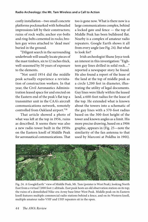
44 The AWA Review
Radio Archeology: the Mt. Tam Wireless and a Call to Action
costly installation—two small concrete platforms pockmarked with hobnailed impressions left by their constructors; ruins of rock walls; anchor eye-bolts and ring-belts cemented in rocks; bro-ken guy wires attached to ‘dead men’ buried in the ground.
“Diligent search in the surrounding underbrush will usually locate pieces of the mast timbers, six to 12 inches thick, well-seasoned by 50 years of exposure to the elements.
“Not until 1954 did the middle peak actually experience a revisita-tion of construction workers. In that year, the Civil Aeronautics Adminis-tration leased space for and erected on the Eastern end of the peak’s flat top a transmitter unit in the CAA’s aircraft communications network, remotely controlled from Oakland airport.”21
That article showed a photo of what was left at the top in 1956, ruins as described. It seems there was also a new radio tower built in the 1950s on the Eastern knoll of Middle Peak for aeronautical communications. That
too is gone now. What is there now is a large communications complex, behind a locked gate and fence — the top of Middle Peak has been bulldozed flat. Nearby is a complex of amateur radio repeaters. Google Earth shows it all from every angle (see Fig. 24). But what to look for?
Irish archeologist Shane Joyce took an interest in this investigation: “Eigh-teen guy lines drilled in solid rock…” reported a newspaper story he found. He also found a report of the lease of the land at the top of middle peak as a circle 1,200 feet in diameter, illus-trating the utility of legal documents. Guy lines were likely within the leased land, a 600-foot radius for the lease of the top. He extended what is known about the towers into a schematic of the guy lines with a 570-foot radius based on the 300-foot height of the tower and known angles as a limit. His more precise drawing, based on a 1906 graphic, appears in (Fig. 25—note the similarity of the fan antenna to that used by Marconi at Poldhu in 1901).
Fig. 24. A GoogleEarth ® view of Middle Peak, Mt. Tam (pointer is West Peak), looking North East from a virtual 7,000 foot ± altitude. East peak hosts an old observation station on its top; the ruins of a demolished Nike-era Army base litter West Peak. Middle peak on its Eastern knoll features multiple commercial radio stations behind a fence, and on its Western knoll, multiple amateur radio VHF and UHF repeaters sit in the open.
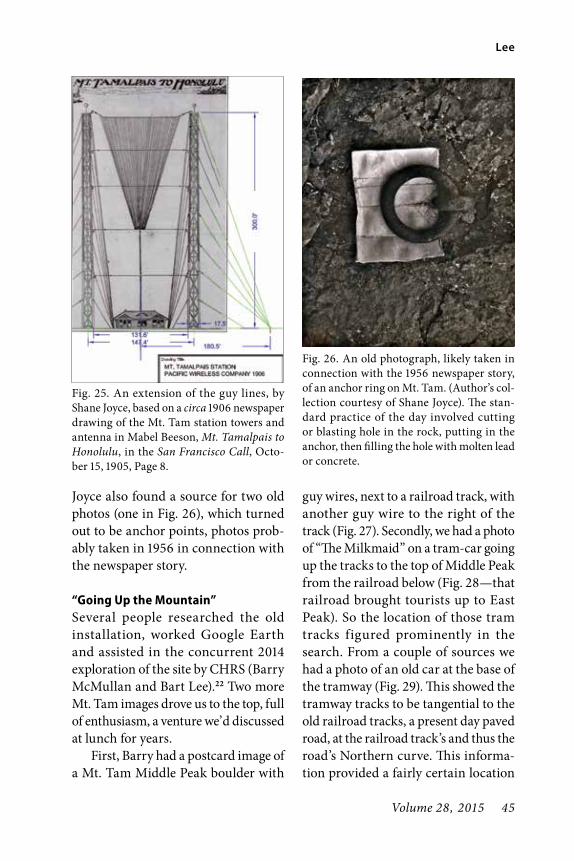
Volume 28, 2015 45
Lee
Joyce also found a source for two old photos (one in Fig. 26), which turned out to be anchor points, photos prob-ably taken in 1956 in connection with the newspaper story.
“Going Up the Mountain”Several people researched the old installation, worked Google Earth and assisted in the concurrent 2014 exploration of the site by CHRS (Barry McMullan and Bart Lee).22 Two more Mt. Tam images drove us to the top, full of enthusiasm, a venture we’d discussed at lunch for years.
First, Barry had a postcard image of a Mt. Tam Middle Peak boulder with
guy wires, next to a railroad track, with another guy wire to the right of the track (Fig. 27). Secondly, we had a photo of “The Milkmaid” on a tram-car going up the tracks to the top of Middle Peak from the railroad below (Fig. 28—that railroad brought tourists up to East Peak). So the location of those tram tracks figured prominently in the search. From a couple of sources we had a photo of an old car at the base of the tramway (Fig. 29). This showed the tramway tracks to be tangential to the old railroad tracks, a present day paved road, at the railroad track’s and thus the road’s Northern curve. This informa-tion provided a fairly certain location
Fig. 25. An extension of the guy lines, by Shane Joyce, based on a circa 1906 newspaper drawing of the Mt. Tam station towers and antenna in Mabel Beeson, Mt. Tamalpais to Honolulu, in the San Francisco Call, Octo-ber 15, 1905, Page 8.
Fig. 26. An old photograph, likely taken in connection with the 1956 newspaper story, of an anchor ring on Mt. Tam. (Author’s col-lection courtesy of Shane Joyce). The stan-dard practice of the day involved cutting or blasting hole in the rock, putting in the anchor, then filling the hole with molten lead or concrete.

46 The AWA Review
Radio Archeology: the Mt. Tam Wireless and a Call to Action
Fig. 27. In this old post card view, the camera looks East to East Peak, down tram tracks from the top of Middle Peak to a railroad below. (McMullan collection). The boulder on the left anchors two guy lines. To the right of the tracks, another guy line also runs up to the left.
Fig. 28. A lady known as “The Milkmaid” appears to be taking milk in jugs (maybe beer?) on the tram up to the workers at the top of Middle Peak, at the wireless station. A thick cable pulls the car up. Such a cable rests on the left side of the tram tracks in the image of the boulder with the guy lines.

Volume 28, 2015 47
Lee
of the end point of the tram—the other end had to be the top of Middle Peak.
So with most of the station bull-dozed and long gone, remnants of the tramway and the guy lines, as well as old timbers, might still be found.
We did; and more. And we photo-graphed it all with meter sticks, North arrows, calipers, etc. The satellite views and topographical maps show the
probable route of the tram tracks when compared with the photographs (Fig. 30). The top is inaccessible and the mid-dle as yet impassible. But the bottom of the tram line track bed had to be next to the road paving over the railroad tracks. There Barry McMullan spotted a tram cable (Fig. 31), about 7 meters of it (22 feet, more or less) about 2.5 cm (one inch ±) in width (Fig. 32) and as corroded as one would expect after more than 100 years exposure to the elements.23 Next to it is a well-decayed railroad tie, like a tie from a tramway (Fig. 33). Moreover, at the top of Middle Peak, outside the fence and by the repeaters, down the slope, McMullen’s sharp eyes spotted a well-decayed timber with old nails in it (Fig. 34). The Mt. Tam wireless tow-ers and its central building had been constructed of such timbers.
As a bonus, McMullan also spot-ted some painted copper antenna wire, likely from the 1950s aeronautical sta-tion,24 and he also found two anchor bolts in a rock, dating from that period (Fig. 35).
This quest succeeded in finding some of the remnants we hoped were still to be found, “adding a tangible dimension to technical studies.” The path of the tramway itself is known, but not yet explored. In the nearby moun-taintop photo, McMullan is scoping out a big nearby boulder for future examination (Fig. 36). We hope that the boulder with the guy wire, appearing in the post card image that first lured us to this site, is still in place on the tram-way. It may be the closest thing we can find to the old station itself.
Fig. 29. A “Stearns” (1900–’04) steam car takes on the tram tracks, or at least the bot-tom few. A staging platform separates the bot-tom of the tramway from the railroad tracks to the right. The Northernmost curve of the tracks appears at the edge of the photo. In the background the observation post at the top of East Peak appears, so again the photograph looks down the tram tracks due East.

48 The AWA Review
Radio Archeology: the Mt. Tam Wireless and a Call to Action
Fig. 30. Looking from the top of the Eastern knoll on Middle Peak down hill and East to the Northernmost curve of the highway over the railroad tracks, a swale appears (between the two lines); this is the most uniform incline up to the top according to topographical maps, and the present foliage pattern could reflect an earlier tram track bed. The commercial radio complex on the top of Middle Peak appears at the bottom right of the image. The ridge behind the road at the top also appears in the Milkmaid image and the boulder with guys image.
Fig. 31. A corroded steel cable, 7 ± meters long, found at the bottom of the presumed tram track bed (Bart Lee photo).
Fig. 32. The corroded cable at the base of the tramway measures just under one inch thick, 2.5 ± cms (Bart Lee photo).

Volume 28, 2015 49
Lee
Fig. 33. A very old railroad tie fragment found next to the corroded cable (Bart Lee photo).
Fig. 34. An old Oak(?) timber at the top of Middle Peak. Nails stick out under the meter sticks. Oak and Fir made up the 1906 wireless station structures at the top (Bart Lee photo).
Fig. 35. Two guy line anchors in a boulder at the top of Middle Peak. The angle suggests a tower near the present commercial stations. These, along with some copper antenna wire, likely remain from the aeronautical station of the mid 1950s (Bart Lee photo).
Fig. 36. Barry McMullan, CHRS, at the top of Middle Peak, Mt. Tam, pointing to a likely site for investigation, a large but oddly flat-topped boulder just outside the fence of the commercial area, possibly an anchor site in 1906, standing “… like stout Cortez when with eagle eyes He star’d at the Pacific—and all his men Look’d at each other with a wild surmise—Silent, upon a peak in Darien” (Keats) (Bart Lee photo).

50 The AWA Review
Radio Archeology: the Mt. Tam Wireless and a Call to Action
A Call to Action—Radio Archeo logy and Adaptive ReuseLast year I wrote to the editor and read-ers of this Review:
“The Antique Wireless Associa-tion, its members and affiliates, now enjoy an opportunity, and (at least from a historical perspective) face a danger. The archeology of radio beckons, but the sites are disappearing fast.
“Archeologists hold that man-kind has flourished through three great ages: the Stone Age, the Bronze Age, and the Iron Age. I suggest that we have entered a fourth: the electrical age. We know the artifacts of the electrical age are at risk. But so too are the sites of the great events, and the small events that give texture to our understanding.
“Industrial archeology seeks to explore, document and preserve our industrial heritage. The rail-road was perhaps the last stage of the Iron Age: the iron horse on steel rails. The telegraph perhaps opened the electrical age: electric-ity over wires for signals, then for power (and industry), then wire-less, radio, television, Radar, com-puters, the Internet. Historians of technology have documented much of this development. Yet many of the sites are unexplored, undocumented and wasting.
“I propose that those of us who can, should take up exploration and documentation of early radio
sites. Radio Archeology prom-ises much new knowledge and perhaps some adventure. As it happens, many of the early sites are seaside, adding to their lure. A few have been preserved, for example Marconi’s Poldhu, Corn-wall, UK transmitter location; a few have succumbed to the ele-ments, for example, Marconi’s Cape Cod “CC” station, lost to the encroaching ocean. Archeolo-gists in Ireland are mapping and exploring the Marconi Clifden site. The Marine Radio Histori-cal Society in Bolinas, California has reinstituted Marconi/RCA marine station KPH/KSM and recently made discoveries about its antenna field and the original KPH site.
“Many agencies, companies and organizations would be pleased to help in documenting their or nearby land and its uses. Some have professional arche-ologists on staff, e.g., the U.S. National Park Service. Many radio journals, perhaps this one, could publish the reports, and encourage further responsible and ethical exploration.
“Time is taking its toll. I hope we can use that inevitability to energize the exploration and documentation of the places of radio history.”
Adaptive reuse is a goal of cultural resources management, and industrial archeology one of its foundations. The

Volume 28, 2015 51
Lee
Opportunities and TextsMany histories talk about these old sites, as they once were—for example, this Antique Wireless Association Review. The AWA Journal also touches on such sites. The regional enthusiasts publications also do so, e.g., the Jour-nal of the California Historical Radio Society. Many years of the publications of the Radio Club of America provide information on old sites. Since at least 1907, various agencies and organi-zations have published station lists, sometimes with locators, but always providing clues. Much local knowledge is available from the senior members of antique radio and amateur radio clubs. Even current roadmaps may show a “Radio Way” worth exploring, for stations needed some infrastructure, and Google Maps is invaluable in this regard (five instant hits). For public lands and government installations, local academic and government (e.g., National Park Service) archeologists
Presidio of San Francisco honors its history, and has put much research and effort into adaptive reuse, including its radio facilities from before and after World War Two,25 with help from the California Historical Radio Society.
The California Historical Radio Society (CHRS), between 2004 and 2014, rehabilitated the abandoned KRE radio station in Berkeley, adapting it for reuse as its radio museum, library, archives, and amateur radio station. (See photos Figs. 37 and 38). CHRS has now bought a 1901 telephone cen-tral exchange building in Alameda for adaptive reuse for the same purposes and as an administrative headquarters for its various programs such as the on-line Bay Area Radio Museum. The California Historical Radio Society, under the leadership of Steve Kushman, President, and Mike Adams, Chairman, is proud to have “walked the walk” of radio archeology and adaptive reuse, at KRE, the new museum, and up Mt. Tam, as well as promotion of its other programs such as its museum.
Fig. 37. The radio station KRE building in 2004, in Berkeley, California (Mike Adams photo).
Fig. 38. The radio station KRE building in 2014, a fully adaptive re-use as the museum and headquarters of the California Historical Radio Society (Mike Adams photo).

52 The AWA Review
Radio Archeology: the Mt. Tam Wireless and a Call to Action
often have information and interest. University archeology departments may provide allies and students will-ing to work.
There are many worthwhile texts26 on various levels. “Archeology for Dummies”27 is quite a good text despite its title. The best set of forms for docu-mentation comes from “The Archeolo-gist’s Fieldwork Companion.”28
Ongoing industrial archeology proj-ects may provide ideas, interactions with professionals, and field experi-ence. For example, archeologists now investigate the English Marconi works at Chemsford29 (Fig. 39).
Conclusion: Save the Radio SitesThe old radio sites are disappearing to the elements, waste and development. Enthusiasts can discover them, explore them, and document them—even in multi-media.30 This foundation enables conservation and adaptive reuse. Detailed documentation and reports foster survival of these sites and fur-thers our understanding of how our modern world came to be.
As for the Pacific Wireless Mt. Tam station,
“The saddest words of tongue or pen are ‘it might have been.’ ”
Fig. 39. A report of contemporary English archeology focusing on the Marconi Chelmsford industrial estate; from British Archeology, April 2013, p. 65.

Volume 28, 2015 53
Lee
Notes1. Christian Thompsen, Danish National
Museum (1819) in D. L. Hardesty, Arche-ology, Vol.1 in UNESCO, Encyclope-dia of Life Support Systems (EOLSS), in full at http://www.eolss.net/Eolss-sampleAllChapter. aspx .
2. Robert A. Clouse, Industrial Archeol-ogy, at http:// www1.umn.edu/ marp/indus/ indus.html (1995). For the Profes-sor’s biography see http://anthropology.ua.edu/ name/Robert%20 Alan/Clouse/.
3. Marconi Project, Failte Ireland National Tourism Development Authority (et al.), 2014, at 22. This promotional booklet displays an outstanding collection of photographs of the Clifden station in its years of operation, 1907 up to the First World War.
4. www.radiomarine.org . The work of MRHS is an outstanding example of Adaptive Reuse of a radio facility. The website features a section devoted to radio archeology.
5. In mid-April, 2012, at sea off the Viet-namese coast, on the upper frequency marine bands (16 and 22 MHz), local daytime, with a Grundig YB-400 and a seven foot wire (author’s observation).
6. MHRS Newsletter No. 12.7. According to Society of Wireless Pio-
neers founder Bill Breniman, a United Wireless and Marconi operator (per-sonal interview, circa 1990). See http://en.wikipedia.org/wiki/Hotel_de_Gink: homeless men’s hotel in the Northwest as of 1913; a “gink” meant an odd fellow and among landline and wireless men it meant a bad operator, but was also used self-depreciatingly.
8. See National Geographic: http://ngm-
beta. nationalgeographic. com/ archive/satellite-archaeology/ .
9. Including 1StopStock, Alamy Images, Amana, Comstock, Digital Vision, Fotosearch, Getty Image, State Master-file, Mauritius Nonstock, Orion Press, Photonica Picture Press, PictureQuest, SuperStock, Wire Image, Workbook Stock, Zefa.
10. See PBS, Tools of the Trade, at www.pbs.org/opb/timeteam/field/tools.php .
11. Popular Mechanics magazine featured the wireless station in an article The Most Powerful Wireless Station Ever Built, in March, 1906, providing this data, according to the story On Mt. Tam, Visitors Can See Ruins of Wireless Sta-tion, in the Marin Independent Journal, December 10, 1956, page 2. Other news-paper reports say 1,200 miles of wire.
12. To Connect With Orient By Wireless Tel-egraph, in the Los Angeles Herald, July 26, 1905 at p. 5.
13. Big Tower being Constructed, in the Oakland Tribune, July 27, 1905, page 3. The San Francisco Call reported on the raising of the first of the two towers after shipment from Oakland, October 12, 1905, page 9. Its story says 44 cables sup-ported the tower.
14. On Mt. Tam, Visitors Can See Ruins… [etc.], fn. 11 above.
15. The World War Two jury-rigged “Fox-hole Radio” of the Italian Campaign worked well with a steel razor blade and a graphite (carbon) pencil lead detector. http://en.wikipedia.org/wiki/Foxhole_radio.
16. Mabel Beeson, Mt. Tamalpais to Hono-lulu, in the San Francisco Call, Octo-ber 15, 1905, Page 8. (http://chronicling

54 The AWA Review
Radio Archeology: the Mt. Tam Wireless and a Call to Action
america.loc.gov/lccn/sn85066387/1905- 10-15/ed-1/seq-8/) and in OCR format: http://chroniclingamerica.loc.gov/lccn/sn85066387/1905-10-15/ed-1/seq-8/ocr/.
17. See note above re On Mt. Tam (1956) and fn. 11.
18. E.g. the Arizona Republican, May 8, 1906, page 6.
19. Haraden Pratt [1891–1969], Sixty years of Wireless and Radio Reminiscences. (typescript circa 1960, from the Perham Foundation files, courtesy of Will Jensby, WØEOM). Pratt also served as a marine wireless operator and a Marconi opera-tor at Bolinas and Marshall.
20. Pacific Wireless effected the first com-mercial wireless telegraphy circuit in 1902. It connected Los Angeles (San Pedro) with Catalina Island. It aimed for a Hawaii circuit in 1906, and regional wireless communications networks in the West.
21. 50 Years Ago Tonight, the World’s Biggest Transmitter, Atop Mt. Tam, Blew Down, [story by] William J. Losh, Dec. 10, 1956, Marin Independent Journal, pps. 1, 2.
22. Special thanks to John Stuart, P.E., CHRS, as well as Shane Joyce in Ireland and John Staples, Ph.D., CHRS, Paul Shinn and Richard Dillman, MRHS, Walt Hayden, CHRS, and Keith Mat-thew, GØWYS of the Poldhu Amateur Radio Club.
23. This cable likely relates to the tram rather than the guy lines because of its position at the bottom of the tramline track-bed. The guy lines were also cables, perhaps from San Francisco’s cable car system or its manufacturers (such cables were used by Federal for its Beach Station in San Francisco in 1910). They terminated
near the top of the hill. A remnant of a guying cable could well have made its way down the hill, but this position would be too fortuitous.
24. Paul Shinn, MRHS, CHRS, who as a broadcast engineer has access within the fence on the East Knoll of Middle Peak, says in “one of the older buildings there [are] the remains of what was once, quite clearly, an extremely large HF instal-lation.” (Personal communication to author).
25. See, e.g., Steven A. Haller and Bartho-lomew Lee, Resurrecting the Presidio’s Historic Radio Network, CRM [Cultural Resources Management, National Park Service] Vol. 40, [Issue] No. 14 (1997) at 33.
26. The Archeology Handbook by Bill McMillon (Wiley, 1991); Assessing Sig-nificance—a Guide for Archeologists… by Donald L. Hardesty and Barbara J. Little (2d ed., AltaMira, 2009); Cultural Resources Archeology by Thomas W. Neuman, et al. (2d ed., AltaMira, 2010).
27. Nancy Marie White, Archeology for Dummies (Wiley, 2008). The two radio-for-dummies books are pretty good too.
28. Barbara Ann Kipper, The Archeolo-gist’s Fieldwork Companion (Blackwell, 2007).
29. Jon Wright, The Marconi Factory, British Archeology, March April 2013 at 65.
30. A superb multi-media example featur-ing computer graphics relates to all of Mount Tam, especially the old Radar station ruins on what was West Peak; Peter Coyote narrates the video: www.marinij.com/marinnews/ci_25146185/mt-tam-documentary-invisible-peak-posted-online.

Volume 28, 2015 55
Lee
About the InvestigatorsBart Lee, K6VK, a Fellow of the Califor-nia Historical Radio Society, in History,
Barry McMullan, CHRS, who led the way up the mountain,
Shane Joyce, Irish Radio-Archeolo-gist, providing invaluable research to advance the quest, and
John Stuart, P.E., KM6QX, CHRS deserves special thanks for tire-less research, drawing and mapping analysis.
About the AuthorBartholomew (Bart) Lee, K6VK, xKV6LEE, WPE2DLT, is a long time member of AWA and a Fellow of the California Historical Radio Society (CHRS), for whom he serves as Gen-eral Counsel Emeritus and Archivist.
He has enjoyed radio and radio-related activities in many parts of the world, most recently in East Africa. Radio technology and history have fascinated him since he made his first crystal set with a razor blade and pen-cil lead more than 50 years ago. He is especially fond of those sets of which it is said: ‘Real Radios Glow in the Dark.’ Bart is a published author on legal subjects and most recently on the history of radio. He has written about and lectured on early radio technology, radio intelligence activities (‘episodes in the ether wars’) from 1901 into the latter 20th Century, wireless telegraphy especially Marconi’s early work, wire-less developments on the West Coast since 1899, radio ephemera including
radio stamps, and radio in emergency and disaster response. Since 1989 he has made some 20 presentations to the AWA conferences on his research inter-ests including short wave radio and the development of television in San Fran-cisco in the 1920s. The AWA presented its Houck Award for documentation to him in 2003 and CHRS made its 1991 ‘Doc’ Herrold Award to him in con-nection with his work for the Perham Foundation Electronics Museum. In 2001, during disaster recovery opera-tions in New York after the ‘9/11’ ter-rorist enormity, he served as the Red Cross deputy communications lead from September 12 to September 21, (the ‘night shift trick chief ’). He has served in RACES as the Liaison Officer for the San Francisco Auxiliary Com-munications System, and as an ARRL ARES Emergency Coordinator.
He presently serves as an ARRL Government Liaison and Volunteer Counsel, and holds an FCC Commer-cial licence (General with RADAR) as well as an Amateur Extra Class licence. Bart has been a litigator by trade, prose-cuting and defending civil cases in both state and federal court for 40 years. He also had taught Law & Economics for 20 years, including the economic history of telecommunications.
He is a graduate of St. John’s Col-lege (the ‘Great Books School’) and the University of Chicago Law School.
Bart’s son Christoffer Lee is also a licensed amateur radio operator and is now also a practicing lawyer. Bart invites correspondence at: KV6LEE@ gmail.com.

56 The AWA Review
Radio Archeology: the Mt. Tam Wireless and a Call to Action
Copyright 2015 by Bart Lee, All Rights Reserved, but any reasonable use may be made of this text (in part or in its entirety, including photographs made by me), respecting my authorship and
its integrity, to further interest in the history of radio. All moral rights are asserted under the Berne Convention and otherwise. Correspondence is invited: KV6LEE @ gmail.com.
Bart Lee atop Mt. Tam, 2014 (Barry McMullan photo).

Volume 28, 2015 57
Edward Weston: The Man and the Meters©2015 Mike Molnar
AbstractIsaac Newton said “If I have seen further it is by standing on the shoulders of giants”. Edward Weston was the giant upon whose shoulders the electrical engineers and inventors of the 19th and 20th century would stand. His many inventions in electrical measurement allowed him to build the accurate, reliable instruments that made their research possible. The familiar Weston meters are only a part of Edward Weston’s long legacy of invention.
Edward Weston ended his career with 334 US patents. He is mostly recog-nized for the surviving Weston Electri-cal Measurement products that bear his name. However, today he is rarely recognized for his earlier accomplish-ments. Electrical measurement was his fourth and final venture into the electri-cal field in the second half of his life.
Weston (Fig. 1) was born on May 9, 1850 in Oswestry, Shropshire, England to a middle class farming family. His father was known for his mechanical ability in the farming community and Edward followed in those footsteps with added interest in chemistry and electricity. He was encouraged to pur-sue these interests in his education. Upon completion of his studies in the sciences, as was common at the time, he apprenticed to become a medical doctor. He soon found that the rigid-ity he had to follow in the treatment of patients at the time stifled his desire to experiment in his areas of interest. He
soon left rural England for London with the hope of a position at the Royal Insti-tution, where his hero Michael Faraday had once done his work.
Fig. 1. Edward Weston.

58 The AWA Review
Edward Weston: The Man and the Meters
Weston, himself, would tell the story of his train trip to London. Along the way he met a very vocal American who was telling all of the passengers about “America, the land of opportunity”.1 When London didn’t provide suitable opportunities, Weston made the deci-sion to leave home for New York. He arrived in 1870 and like many immi-grants he had little money, but was will-ing to work hard. He would soon make America his land of opportunity. In a short time Weston would become an inventor, engineer and industry leader in four businesses. He would get his start with electroplating.
Weston and ElectroplatingElectroplating, the process of using electric current to coat common metals with a thin layer of gold, silver or nickel to produce a fine finish, had become commonplace by 1870. However the ability to do quality, durable work, was not as commonplace. As the little money he had was running out, Weston was able to get employment in the elec-troplating field. He was able to show his abilities by solving his employer’s problems and greatly improving his work. He also learned his first lesson in American business. The company that hired Weston was the American Nickel Plating Co. and he quickly improved their operation, making it one of the largest electroplating firms in New York. The owner of the com-pany was primarily a stock and com-modities trader. In 1872 speculators had caused a shortage in the nickel needed for plating and the owner was one of
the speculators. While the quality of work had made American Nickel Plat-ing Company one of the best, Weston soon found that the company could not get the nickel they needed to fill their orders. He learned that although the owner had control of enough nickel, he would make more money trading nickel on the commodities market. All of Weston’s efforts could not stop his employer from closing the business Weston had made successful.2
Since he had no funds, Weston earned some money with a small pho-tographic studio in his home. Barely getting by, Weston soon found a part-ner willing and able to finance a plating company. The company of Harris and Weston Electroplating was formed and opened for business in 1872. Edward Weston, at the age of 22, now had started his first business. Although the company was doing quality work, the timing for starting a new business was unfortunate as the Financial Panic of 1873 took hold of the country. The com-pany weathered this period thanks to Weston’s hard work, enabling the com-pany to do the best plating on the most varied objects. His work in this period led to his first patents, the first one for a new nickel anode and the next for an improvement in the plating solution. He also developed a process to plate with malleable nickel which improved the durability of the plating.
Soon another hard lesson in Ameri-can business be learned by Weston. The original patents for electroplating were held by Dr. Isaac Adams. The company to whom he had assigned the patents

Volume 28, 2015 59
Molnar
brought legal action against other plat-ing companies. The US Patent Office had granted very broad claims in the original patent for electroplating. The original work of Weston and others had greatly improved the initial pro-cess of electroplating. This held little value in court as the legal fight was lost. Weston’s partner, who only saw the business as an investment, left Weston to stand and fight alone. Weston would leave the electroplating field that he had mastered and closed the first business he had started.3
Weston and DynamosDuring his time as an expert in elec-troplating, Weston discovered and solved many problems he found in the plating process. He confronted every fault resulting from contaminated chemicals, poorly prepared materials and insufficient current from the bat-teries in use. At the time, the preferred source of current was a battery of Smee Cells. Invented by Alfred Smee in 1840, it was an improvement on the origi-nal Voltaic Cell. Weston saw the bat-tery of Smee Cells as insufficient and unreliable for the plating business and he started using a dynamo of his own construction. The dynamo converts mechanical power into a steady direct current, often driven by a steam engine. Knowing that the available dynamos at that time were too inefficient to be cost effective, he set about designing his own. The Weston Dynamo Electric Machine Co. was started in Newark in 1877. When Weston started his second business venture, he was 27 years old.
It was the first company to exclu-sively produce dynamos.
Weston began a complete analysis of the problems with the dynamos of the time and soon was granted a pat-ent for the “Rational Construction of a Dynamo”. He also patented use of the laminated construction of pole pieces to reduce eddy currents. His design incor-porated other innovations including methods of producing more efficient windings and methods of cooling the dynamo. Weston would control every aspect of this business including mak-ing the sales presentations to compa-nies he knew would benefit from his dynamo. He entered his dynamo at electrical exhibitions winning prizes and gaining recognition in the elec-trical industry. His entry at the Paris Mechanical Exhibition in 1878 would be awarded the Bronze Medal.4 Soon Weston saw that increasing interest in arc lighting would not only create the potential of a large market for his dyna-mos, but also a new field in which to focus his inventive talents. After giving one of the first public demonstrations of the arc light and installing lights in his dynamo factory, it was clear that Weston would soon be starting his third business at the age of 30.
Weston and Arc/Incandescent LightingSince Weston had become a recognized leader in dynamo design and manufac-turing, it was only natural that he would want to experiment with arc lighting. Although the principle of the arc light had been known for some time, the

60 The AWA Review
Edward Weston: The Man and the Meters
early demonstrations were done with batteries. Scientist Humphrey Davy’s experiment in 1820 required a battery of two thousand voltaic cells. It would take decades before improvements in dynamo efficiency would make the arc light a practical device. Weston built his first arc light in 1872, and made one of the first public arc light demonstrations. He also used an arc light in his shop. (Fig. 2) He confronted the problems with arc lighting and received a num-ber of patents over the next few years. The Weston Electric Lighting Company was formed in 1880 and Weston’s arc lamp soon became a leader in the field. There were no standards for lighting systems in the beginning and buyers did not discriminate between systems. Weston’s arc lights were mechanically
well made and included regulators and cut outs that would allow other lights wired in series to continue running when one failed. Another important factor in an arc lighting system was the use of carbon rods to produce the arc. At the time, the rods were imported from Europe and considered too expen-sive. Weston used his past experience in chemistry to produce an improved car-bon rod. The improvements included copper plating the ends of the rods for better electrical contact and mixing other components with the carbon to improve the color of the arc. The final product was a carbon rod with a soft metal core which he produced eco-nomically in a high pressure press. For 79 cents per 12 inch rod, a pair would burn for 8 hours, half the cost of the imported rods. Weston carbon rods were the best value and were used not only in Weston arc lights but also in arc lights produced by his competitors.5
The combination of the most effi-cient dynamos, a superior arc light and the best carbon rods, made the Weston System a leader. Soon performance and efficiency became important factors to buyers and poorly designed systems fell out of favor. Weston constructed a central station in Newark that served 300 arc lights for his customers (Fig. 3). This complete system made people take notice. The Weston System was chosen for the premier lighting project of the day. In 1883 the new Brooklyn Bridge would be lit by a Weston system. (Fig. 4) The Weston Electric Lighting Com-pany soon became a takeover target. The United States Electric Lighting Fig. 2. Weston Arc Lights.

Volume 28, 2015 61
Molnar
Company was formed to bring invest-ment capital to the lighting business. This company hired inventors includ-ing the famous Hiram Maxim. It also purchased patents and companies. In 1884 the United States Electric Lighting Company was able to acquire a major-ity of shares in the Weston Electric Lighting Company and Weston was hired as chief electrician and director of manufacturing.
By this time, inventors realized that arc lighting would never be suitable for residential use. In his new position, Weston had the opportunity to join the ranks of many inventors research-ing incandescent lights. The elements that were needed to produce the lamp were becoming well known and Weston was well suited to address them. The earliest builders of incandescent lamps searched for the best fibers nature could offer for their lamp filaments. The per-fect filament they sought would pro-duce the best light for the longest time and at the lowest cost. Edison sent assis-tants around the world to send back samples of bamboo and anything else they thought worth testing. All natu-ral fibers had the same problem. None were homogeneous enough to be the perfect filament. Weston took a dif-ferent approach. Just as he had done with cellulose, he fabricated sheets of his own material. These sheets were then cut down to produce filaments. Weston named this material Tamadine and patented it in September 1882. From 1883 to 1893, Tamadine became the material of choice for many of the lamps that competed against Edison’s bamboo filament.
Even the best filaments still had weak spots. Weston again used an ear-lier experience to solve the problem. He invented a system of flashing to repair weak spots in Tamadine filaments. He found that when he heated the filament in a hydrocarbon atmosphere the weak spots would overheat. This heat would attract the carbon from the gas and the carbon would collect to repair and Fig. 4. Weston Lights Brooklyn Bridge.
Fig. 3. Weston Central Station.

62 The AWA Review
Edward Weston: The Man and the Meters
strengthen the weak spots. This was a second major invention that would be used by the entire lighting industry. (Fig. 5) Although Weston was granted a patent by a patent office tribunal, it would be denied by an appeals court. William E. Sawyer of the Sawyer-Mann company independently developed the same process. Weston was unable to produce sufficient proof of his date of invention but the legal process delayed a final decision until the patent had little value because Edison’s patents were enforced.
In addition to other innovations in evacuating lamps, Weston also devel-oped a chemical getter using Thorium Oxide. This process consisted of plac-ing the Thorium Oxide inside the glass globe of the lamp. It would be kept heated as the lamp was evacuated. After
the globe was sealed the getter would cool and then react with any remaining oxygen. The oxygen, now combined with the getter was thus removed from the atmosphere of the lamp. Although there were several other getter processes in use, Weston received two patents for his process. Many years later, this method also became common practice in the manufacture of radio vacuum tubes and can often be seen as the shiny black coating inside the glass.
Many histories of the incandes-cent light have been written. Many authors promote their favorite inven-tors. However, there is reason to believe that Weston’s inventions and innova-tions enabled the United States Electric Lighting Company to produce the best lamps in the business. The company would claim that its lamps burned more efficiently and for over 2000 hours, twice as long as competitor’s lamps would last.6 In the late 1880s, there were many patent battles over the lighting business. Weston spent a great deal of his time testifying in court. He soon became recognized for his clear understanding of the issues and presen-tation of the technology. After Edison had his incandescent systems up and running, the Edison Company took steps to enforce its patents. This soon made it impossible for other companies to compete. Weston had done battle with Edison both in court and in public. Weston had the reputation as a fighter and in a letter to the Scientific Ameri-can of November 1, 1879, he would call Edison’s claims regarding Edison’s dynamo, “manifestly absurd”.7 But the Fig. 5. Weston Tamidine Lamp.

Volume 28, 2015 63
Molnar
Edison patent victory weakened the position of the United States Electric Lighting Company, and it soon was taken over by Westinghouse. The West-inghouse Company needed to build up a stronger position to do battle with Edison and General Electric. When Westinghouse took over the lighting business, Weston left the company. During his time in business, Weston had become an experienced witness in patent hearings. He had built a reputa-tion with law firms for making clear presentations. He was asked to act as an expert witness for law firms. Weston continued to freelance as an expert wit-ness in the many patent hearings of the day. He created a small laboratory of his own to produce courtroom models and to prepare demonstrations. (Fig. 6)
Electrical Measurement Prior to WestonTo appreciate the value of Weston’s work, we need to understand the meth-ods used to make electrical measure-ments before his inventions. Francis Jehl, an assistant to Thomas Edison from the earliest days in Menlo Park, was given the task of determining the
voltages and currents required by the first incandescent lamps. The first crude measurements were accomplished by measuring the horsepower needed from the steam engines turning the electri-cal dynamos, and ultimately, from the amount of fuel used. Jehl concluded that getting more precise measurement of individual lamps would prove much more difficult.
The instruments available at that time included a Thompson high resis-tance galvanometer to measure electri-cal current and a quadrant electrometer to measure electrical potential. Using fixed resistances, Clark cells and Wheatstone bridges, taking measure-ments was tedious and painstaking. Edison also used an electrodynamom-eter, which sent current through large fixed coils which would then deflect a smaller movable coil. This required hours of setup time and additional hours to take measurements and per-form calculations. Several measure-ments would be taken and since no two readings were the same, an aver-age of all of the measurements would have to be calculated. Edison said of the electrodynamometer “It’s a mighty fine scientific looking instrument, but it doesn’t work”.8 The Deposition Cell was another simple but time consuming device to measure current. Current was sent through a Deposition Cell for sev-eral hours and the average current was calculated by measuring the change in weight of the metal plate element in the cell. The final result reported to Edison was a judgment call based on a com-parison of all results and confidence in
Fig. 6. Weston Lab.

64 The AWA Review
Edward Weston: The Man and the Meters
the instruments. Many of the instru-ments were so sensitive to vibration that for stability a calibration table was built on brick piers set 10 feet deep.
To measure the energy consumed by a lamp, the method used was a water calorimeter. The lamp was placed in a container with a fixed amount of water and a thermometer. The energy used was determined by the time needed to raise the water temperature a fixed amount. Francis Jehl called this an “instrument of congeniality” since workers stayed for hours just to main-tain a constant voltage and current from the dynamo. This gave them plenty of time to swap stories among friends as the water temperature slowly rose.9
Weston and Electrical MeasurementThe difficulties in taking measurements also affected Weston. Weston had a
display at the Franklin Institute Electri-cal Exhibition in Philadelphia in 1884. (Fig. 7) In order to set up the display, he had to measure the performance of the dynamos and lighting prod-ucts. Using the instruments available, it took Weston one week to take and confirm the measurements. Weston’s own experiences identified the need for easy and accurate electrical measure-ment.10 He already had set up his own laboratory during the period of his con-sulting activities as an expert witness. He began to use his lab to investigate the requirements needed to improve electrical measurement. With a small group of investors, Weston, at the age of 38, (Fig.8) formed his fourth and final company. The Weston Electrical Instrument Company was started on March 31, 1888 in Weston’s home labo-ratory. His associates soon convinced
Fig. 7. Weston Exhibit.
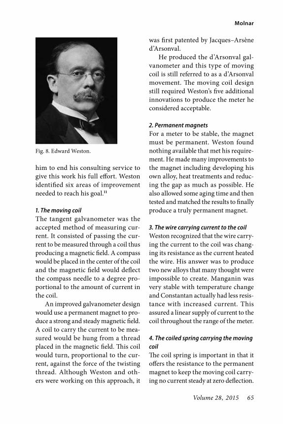
Volume 28, 2015 65
Molnar
him to end his consulting service to give this work his full effort. Weston identified six areas of improvement needed to reach his goal.11
1. The moving coilThe tangent galvanometer was the accepted method of measuring cur-rent. It consisted of passing the cur-rent to be measured through a coil thus producing a magnetic field. A compass would be placed in the center of the coil and the magnetic field would deflect the compass needle to a degree pro-portional to the amount of current in the coil.
An improved galvanometer design would use a permanent magnet to pro-duce a strong and steady magnetic field. A coil to carry the current to be mea-sured would be hung from a thread placed in the magnetic field. This coil would turn, proportional to the cur-rent, against the force of the twisting thread. Although Weston and oth-ers were working on this approach, it
was first patented by Jacques–Arsène d’Arsonval.
He produced the d’Arsonval gal-vanometer and this type of moving coil is still referred to as a d’Arsonval movement. The moving coil design still required Weston’s five additional innovations to produce the meter he considered acceptable.
2. Permanent magnetsFor a meter to be stable, the magnet must be permanent. Weston found nothing available that met his require-ment. He made many improvements to the magnet including developing his own alloy, heat treatments and reduc-ing the gap as much as possible. He also allowed some aging time and then tested and matched the results to finally produce a truly permanent magnet.
3. The wire carrying current to the coilWeston recognized that the wire carry-ing the current to the coil was chang-ing its resistance as the current heated the wire. His answer was to produce two new alloys that many thought were impossible to create. Manganin was very stable with temperature change and Constantan actually had less resis-tance with increased current. This assured a linear supply of current to the coil throughout the range of the meter.
4. The coiled spring carrying the moving coilThe coil spring is important in that it offers the resistance to the permanent magnet to keep the moving coil carry-ing no current steady at zero deflection.
Fig. 8. Edward Weston.

66 The AWA Review
Edward Weston: The Man and the Meters
It also resists the deflection caused by the magnetic field generated in pro-portion to the current to be measured. Weston found that the steel springs available to be insufficient. He created a low resistance copper alloy that had fine elastic qualities and was non-mag-netic. He also used a jeweled sapphire movement to support the top and bot-tom of the coil.
5. Improving the coilWeston improved the performance of moving coils by producing a light aluminum frame for the coil. This not only maintained the shape of the coil but also had the added benefit of induc-ing eddy currents in the frame itself that caused a drag through the field of the permanent magnet. This reduced the oscillation before it came to a stop, thereby allowing the indicator to give a stable result quickly.
6. Electrical shunts to measure high currentsFine coils in a meter cannot measure large amounts of current. Weston’s answer was to divert a fixed percentage of current around the delicate moving coil through a shunt. The coil actually measures only the minute amount of current that was not shunted. By know-ing the percentage of current going through the shunt, the meter scale could be calibrated to represent the full current through coil and shunt. After much experimentation, Weston used Manganin, the alloy he created that maintains a constant resistance independent of the amount of current
and the temperature. The shunt circuit was patented in 1893 and was used in Weston products. (Fig. 9)
The MetersWeston always wanted to improve his products. By 1888 he had made prog-ress on all of the requirements for his meters except the shunt. Convinced that the meter he could produce would be the best meter on the market, he began production of the Weston Stan-dard Portable Meter. His solution to making his meter as accurate as pos-sible is seen on the early version of the Standard Portable Meter. (Fig. 10) A built-in thermometer indicated where to set the temperature compensation dial. This temperature adjustment satisfied Weston that his meter was as accurate as possible. He was persistent, continually working on improving the instrument. When Weston was able to introduce his temperature stable alloys
Fig. 9. Moving coil.

Volume 28, 2015 67
Molnar
he was able to eliminate the need for the temperature compensation control. The thermometer and dial were later removed on the same model meter. (Fig.11)
Weston would incorporate all of these improvements into the Model 1. He considered this to be the first accu-rate, reliable, compact and truly por-table meter. (Fig. 12) These features were of great importance to the labs and schools of the day. All electrical meters
were costly at the time. The ability to have one meter that could be passed around to different technicians or stu-dents, who could then obtain quick and accurate readings without checking for temperature changes or needing cali-bration was a great benefit.
Although many examples of Weston meters survive, the model, serial num-bers, patent numbers and calibration tags are often confusing and difficult to understand. The date of production can
Fig. 10. Early Standard Meter last calibrated in 1895.
Fig. 11. Weston Standard Meters. Fig. 12. Early Model 1.

68 The AWA Review
Edward Weston: The Man and the Meters
rarely be determined from the patent dates or calibration dates. This is largely due to the methods used in sales and production. The Weston Company saw no need to produce new catalogs or to have new model numbers each year. The Model 1, for example, was in production for decades. When a customer ordered a Model 1, he would choose from the dif-ferent configurations that were offered. This model could be specified for AC, DC, both AC/DC or resistance, all in wide ranges. This philosophy was used for all of the products. The number of products was continually growing to meet the demands of industry. In 1900 there were 28 products, by 1904 there were 280 and after 1919 over 400 prod-ucts.12 In addition to the number of products to choose from, the customer was able to choose from hundreds of
variations.13 Later the company would release circulars covering specific prod-uct lines such as Radio Circular J of 1928.
When instruments were sent to the factory for calibration they would be upgraded to the latest version of that instrument. At that time the calibra-tion sheet of paper would be exchanged showing the newest data and calibra-tion date. Although this is all confusing when viewed today it was not confusing at the Weston Company. The company maintained an archive of records for every product built and every time it was serviced or upgraded. (Fig. 14)
Power Station MetersWeston meters were commonly used in schools and laboratories. It was obvious to Weston, however, that the biggest
Fig. 14. Records Archive.

Volume 28, 2015 69
Molnar
demand would be for power station meters. (Fig. 15) The electrification of the United States was beginning and this produced increasing demand for meters. A casual examination of surviv-ing meters shows serial numbers on lab-oratory meters in the thousands while power station meter serial numbers reach well into the tens of thousands. Before Weston, the equipment avail-able to central stations at the time was inefficient and inaccurate. To measure large currents, the full current would pass to the device through a copper bar. The associated losses caused the meter to consume considerable power. Since Weston was passing most of the current through the shunt and only a minute fraction was sent through the
meter, he could actually show that his meter would reduce the annual cost of operating the power station meters from hundreds of dollars to a few cents. This made the decision for a station manager to buy new Weston meters an easy one.14
Other AccomplishmentsAnother major accomplishment was the development of the Weston Standard Cell. In 1911, the International Con-ference on Electrical Units and Stan-dards declared it the official standard for measuring the volt. Standard cells had been used in the past as a voltage source and a tool to check the accuracy of meters. Weston’s innovative use of cadmium produced a much more reli-able output of 1.0183 volts. To aid the electrical industry Weston turned over patent rights to this cell to all parties.15 Weston was the first to offer the radio industry a meter to directly measure radio frequency current as well as the first radio test set.
Company publications show the production, over the years, of hundreds of models of instruments with thou-sands of variations, many built for the government and the military. However, in 1935, after Weston’s retirement, a patent issued to his son, Edward Farady Weston, would lead to another prod-uct that set a standard, pioneering a new field of measurement. The Weston Company, in its second 50 years, would become famous for exposure meters, setting new standards for photogra-phers. The company worked with the photographic industry to set standards Fig. 15. Power station meters.

70 The AWA Review
Edward Weston: The Man and the Meters
for exposure time, aperture settings and film speeds to enable exposure meters to measure the light and calculate the correct settings. There were 36 varia-tions of exposure meters produced.16
Weston Electrical Instruments did not forget its roots in electric meters. The company would continue to develop meters into the digital era, incorporat-ing displays using Nixie tubes, LEDs, and LCD read-outs. (Fig. 16)
The Weston LegacyEdward Weston’s personal legacy is an American success story. From his arrival in New York and struggle to find work, to becoming a renowned inventor and creating four businesses, his story is one of living the American dream. Weston would retire from his company at the age of 80, turning over his position to his son, in 1930. (Fig. 17) At this time he was 8th on the list of individuals with the most US patents. He is listed in the New Jersey Inventors Hall of Fame and received many awards in his lifetime. His accomplishments
in chemistry and electricity fill a long list. (Fig. 18) His processes for produc-ing Tamadine are considered the basis for the production of Rayon and Cel-lophane. He was awarded the Perkin Medal in 1915. The Franklin Institute awarded him the Franklin Medal in 1924 and he was awarded the Lamme Medal in 1932. During his later years, Weston helped found the Newark Tech-nical School. This school would later become Newark College of Engineer-ing and is now the New Jersey Insti-tute of Technology. Weston was also a founding member and past president of the AIEE, which later became the IEEE. After enjoying a retirement that included time spent yachting, Edward Weston passed away in 1936. The results of his work would live on much longer.
The Weston Electrical Instrument Corporation followed a creed set by its founder. He did not want a company obsessed with size or sensationalism. The company’s purpose was not to pro-duce the most meters at the highest profit but rather to develop new instru-ments so fine that they would widen and improve the use of electricity. After
Fig. 16. Weston Digital Meters.
Fig. 17. Edward Weston, later years.

Volume 28, 2015 71
Molnar
the retirement of the founder, the com-pany was headed by his son, Edward Faraday Weston (1878–1971). He would continue running the company follow-ing in his father’s footsteps. The com-pany creed would be restated in a 50th anniversary company publication, “This policy of serving, of helping scientists prove new phenomena, engineers per-fect new designs, and manufacturers produce new devices, has guided the Weston company from the beginning”.17 This policy brought success and a con-tinuous stream of invention for over a century. These inventions include improvements to existing products as well as research into new products to meet new demands unimagined in the early days of the company. From the small lab built behind Weston’s home, the company would grow into
the industrial complex shown in this 1906 company photograph. (Fig. 19)
As the result of mergers and acqui-sitions, the company would become associated with other names such as Sangamo, Schlumberger and Solartron, the name of Weston Aerospace came into use. In 2003 Weston Aerospace became a part of Esterline Advanced
Fig. 19. Weston plant in 1906.
Fig. 18. Edward Weston was the man who.

72 The AWA Review
Edward Weston: The Man and the Meters
Sensors and today is part of Esterline Technologies Corporation based in Bel-levue, Washington.
References1. Woodbury, David O., A Measure for
Greatness, 1949 McGraw Hill Book Co. New York, NY p 24.
2. Ibid. p 39.3. Ibid. p 47.4. Ibid. p 84.5. Ibid. p 94.6. Burns, Bill, Weston Electrical Instrument
Corp, 2011–2014 History of Technology www.ftldesign.com p 1.
7. Hintze, Christine, Edward Weston: A Dynamic Electrical Engineer, Oct. 2006 www.electronicdesign.com /lighting/EdwardWeston p 1.
8. Jehl, Francis, Menlo Park Reminiscences 1937, 1990 Dover Publications Inc. New York, NY p 364.
9. Ibid. p 365.10. F. Lawrence Babcock Co., Measur-
ing Invisibles, 1938 Weston Electrical Instrument Corp. Newark, NJ p 19.
11. Ibid. p 24, 25.12. Ibid. p 34.13. Ibid. p 8.14. Woodbury, David O. p 18115. Ibid. p 191.16. The Chronology, www.westonmeter.org17. F. Lawrence Babcock Co. p 6.
Photo CreditsFigures 1, 3, 4, 6, 7. Woodbury, David O., A
Measure for Greatness, 1949 McGraw Hill Book Co. New York, NY
Figures 14, 17, 18, 19. F. Lawrence Babcock Co., Measuring Invisibles, 1938 Weston Electrical Instrument Corp. Newark, NJ
Figure 9. Wikipedia, d’ArsonvalFigures 2, 5. Burns, Bill, Weston Electrical
Instrument Corp, 2011–2014 History of Technology www.ftldesign.com
Figure 8. Hintze, Christine, Edward Wes-ton: A Dynamic Electrical Engineer, Oct. 2006 www.electronicdesign.com /lighting/EdwardWeston
Figures 10, 11, 12, 13, 15, 16. The author’s col-lection www.electronicfossil.com
About the AuthorMike Molnar started Diagnostic Ser-vices Inc. in 1983. Mike is still busy running the company, designing and building nuclear medicine equipment for equine and small animal veterinary use. A long time AWA member and collector, his interest in old radio, TV and electronics continues. His large collection is still growing and available for many to see at electronicfossil.com. With the help of his patient wife Pam, Mike serves as caretaker of the fossils.
Snow and ice can’t stop author Mike Molnar and loyal helper Lila from uncovering more electronic fossils.

Volume 28, 2015 73
The First Broad cast FM Auto Radio—Motorola FM-900
©2015 Ray Schulenberg and Olin Shuler
AbstractThe promises of FM radio being of high quality and static-free made it a logical offering for a car radio. An FM car radio project was launched at Motorola in 1959, 30 years on from when Motorola had first entered the car radio business. It would be known as the Model FM-900, and Ray Schulenberg was assigned as the electri-cal design engineer. Ray describes the design activity first-hand, and initial tests are summarized in detail. Preparations at the assembly plant are described by Olin Shuler, production engineer. The assembly went very smoothly, indicating that the initial design was well conceived. The model went into production and continued for about four years, with not one electrical design change required, a remarkable feat indicating a well-thought-out design.
superior sound quality. But, In order to fully appreciate FM’s benefits, more powerful receivers, amplifiers, and large high fidelity speakers were necessary. This restricted optimum enjoyment of FM to the confined quarters of the fam-ily living room or den. Sound reproduc-tion from smaller inexpensive FM table model radios, with five inch speakers and little more than a watt of audio output, did not sound noticeably better than an AM set. No real advantage was apparent to many listeners.
It was difficult for a fledgling FM broadcaster to distinctively stand out, sell advertising and make money. Propagation characteristics of the new
IntroductionThe early promises of high quality, static-free, FM radio broadcast recep-tion began to come true in the spring of 1941. Five commercial FM stations were fully licensed and on the air in Mt. Washington NH, Chicago, Mil-waukee, Nashville, and New York, in the 42 to 50 MHz band.1 World War II interrupted further significant growth. Advancements in the technology dur-ing the war resulted in relocating FM broadcasting to the present 88 to 108 MHz band.
At war’s end the growth of FM broad casting resumed, enabling the static free reception as promised, with

74 The AWA Review
The First Broad cast FM Auto Radio—Motorola FM-900
88-108 MHz FM band limited the cov-erage area. Lower powered FM stations had issues caused by marginal audience coverage. By the early 1950s FM broad-casting began to decline, particularly in the smaller outlying regional markets
Those remaining on the air largely carried the same programming as their AM counterparts. The growth of televi-sion was siphoning the home entertain-ment dollars away from AM as well as FM radio. The high fidelity market was slowly growing, largely supported by high end hardware, quality vinyl stereo, and audio tape. But new FM table model radios were disappearing from manufacturers’ annual product introduction line-ups.
Results of a survey reported in Pop-ular Electronics Magazine disclosed that none of the major radio manu-facturers had plans to offer an FM car radio any time soon. Motorola was quoted as one of the respondents with a NO answer.2 In 1958 Ford Motor
Company offered an ”FM-tuner” as a dealer installed option for the Lin-coln.3 But, it used the existing AM radio audio amplifier and speakers. Not well received, by 1959 the option was discon-tinued. —But change was in the wind!
In late 1958, trade journals were announcing that FM subcarrier pro-gramming, imbedded in existing FM broadcast signals (multiplexing), would soon be approved by the FCC, launching background music service as a new source of income for broad-casters. Approval of FM Stereo was also eminent, enabling FM broadcast-ers to compete with stereo LP records and tape. Small manufacturers were entering the auto radio scene with FM converters operating through AM car radios with their inherent sound qual-ity limitations. With this information at hand, minds began to change in the Motorola Executive Suites and the FM car radio project was launched in the second quarter of 1959.
Fig. 1. Introduction in Motorola Dealer’s catalog, 1960.

Volume 28, 2015 75
Schulenberg and Shuler
It would be known as the Model FM-900; a complete high performance radio, with pleasing sound capability, not a “tuner or converter”. It would be designed by Motorola Distributor Auto Radio Engineering; later-day succes-sors of the seminal group that launched Motorola in the auto radio business 30 years earlier. Sold through Motorola distributors and dealers, it would fetch a target retail price of $125; less than 5% of the cost of a new car. Engineer-ing Manager Al Arnold assigned Ray Schulenberg as Electrical Design Engi-neer and Bill Race as the Mechanical Design Engineer. Herb Zeller was the Design Stylist.
Ray Schulenberg, Design Engineer, describes the design activityThe engineering team went to work. Utilizing existing knowledge of size and space limitations for under-dash after-market automobile radios, we
settled on an optimum chassis size and the locations available under the dashboards of late model cars. Sensi-tivity and impeccable sound quality were the obvious goals. The question was not “what is the minimum we can get by with?”, but rather “what is the best fringe area reception, urban recep-tion, audio power and fidelity we can we obtain?” We recognized what it would likely take to be successful and acted accordingly. Performance requirements dictated the selection of circuits and features.
In the automobile world, new designs begin with a test “Mule”; an early rendition of the intended size and shape of the new vehicle. And so it was with the first working model of the FM 900 used for development and tests in the field. Known as the “Design Model”, it included perme-ability RF tuning, grounded-grid RF stage, converter, two IF stages, two
Fig. 2. FM 900 and power supply from the pre-production pilot run. Note tape on the top cover indicating the set was one of the first 10 assembled. Those used tuners pre-aligned before installation. Pre-alignment was successful.

76 The AWA Review
The First Broad cast FM Auto Radio—Motorola FM-900
limiter stages, AGC, full-time varicap AFC, a ratio detector, two audio stages (all vacuum tubes) and push pull output transistors. The 90 volt B+ source for the vacuum tubes came from a small power supply, mounted separately from the radio. It was an early version of a
switching power supply, using a free-running power transistor oscillator. A transformer and selenium rectifier with appropriate RC filtering completed the unit. Mounted out of sight, it enabled the radio to occupy minimum space on the lower lip of the dashboard.
Mechanical engineer, Bill Race and his team attended to the “mechanical packaging” inside the radio chassis. Carefully planned placement of the tuner, IF coils, tube sockets and related transformers led to neat compact pre-liminary design. Unique mechanical parts were fabricated in the model shop and the first Design Model chassis came in to being. Meanwhile, blue-prints and production tooling details were conveyed to mechanical parts suppliers.
Fig. 4. Switching power supply, with cover removed, provides 90 volts B+ for the vacuum tubes.
Fig. 3. Model and serial identification. Chassis were not sent down the line in serial number order. At the time it was not seen as a histori-cal event.

Volume 28, 2015 77
Schulenberg and Shuler
Radio circuitry advanced from the lab breadboard development stage, to wiring in the Design Model chassis step by step to completion. Alignment, bench tests, and round-one of optimi-zation followed. Then, with lab per-formance documented as a quantified base line, the Design Model, a speaker, a 30-inch whip antenna, a couple of tool and equipment boxes, and sometimes an accompanying lab technician, were loaded into a test car. Task of field test-ing began.
Over a period of several weeks vir-tually every good or difficult recep-tion location in the Chicago area was surveyed, covering a 60+ mile radius extending into Wisconsin, Indiana and Michigan. FM reception needed to be comparable to AM, (or better), with particular attention in urban areas with
underpasses, parking garages, and sig-nals that reflected from large buildings. As the need for additional sensitivity and higher gain in the IF strip was realized, tube shields were added to assure stability. A slight mechanical re-arrangement of the tubes and IF coils was made to accommodate them, and ease assembly and serviceability issues. Heat chamber tests of the push-pull transistor output stage brought forth a more effective transistor heat sink. Each day in the field, led to more hours in the lab, incrementally confirming and measuring the improvements that would be included in the design. This was followed by trips back to the field to verify the results. —And repeat the cycle. Fringe area reception and inter-action of strong competing signals provided the conditions necessary to
Fig. 5. Underside of main IF and audio chassis. Note shields and bonding foils.

78 The AWA Review
The First Broad cast FM Auto Radio—Motorola FM-900
optimize AGC and AFC action. The field and lab work was interspersed with periodic project progress report meetings and demonstration trips with executives.
When mechanical parts containing all the latest revisions were available from the model shop, a final version of the Design Model was assembled for the latter stages of field tests. As tests
progressed, with the optimizing steps quantified and included in the design, the point was reached where perfor-mance goals were met and the design was accepted for release to production. The finalized design delivered 15 watts of peak audio power, with minimal dis-tortion even at higher listening levels. Weak signal sensitivity for 10 db qui-eting was less than 3 micro-volts, and
Fig. 6. Overall view with covers removed.
Fig. 7. RF deck, showing antenna coil trim-mer. Note that the IF coil mount is tilted to enable access for adjustment.
Fig. 8. RF deck. Mark on output transformer frame is indication the set had passed pre-test inspections. Note test acceptance sticker on the IF coil.

Volume 28, 2015 79
Schulenberg and Shuler
with limiting (no background noise) at 10 micro-volts or less. Meantime, Stylist Designer Herb Zeller had cre-ated a smart looking chrome plated escutcheon, a very attractive dial glass and scale, with nicely proportioned knobs. His results are best described as “very 1960!” Gorgeous!
Representatives from the manu-facturing plant attended a “screening meeting”, having their first exposure to the product that would soon be manu-factured at the Quincy plant. As the final design came together, the Design Approval Run consisting of five sets, was assembled in the engineering lab. Performance was documented and the sets were used for additional field performance testing in selected loca-tions, to confirm design integrity. Two went to the factory as official design samples. With all revisions in place the bill of materials and related specifica-tions and blueprints were brought up to date. Approximately nine months after starting the project the official release date arrived. As the electrical design engineer, I was chosen to accompany Division Vice President Ed Taylor to the official press-conference announcement of the FM 900 at a hotel in the loop in downtown Chicago.
Olin Shuler, Production Engineer, describes preparations at the factoryBasic production planning was under way early, with major equipment needs identified and acquired. The production pilot run was set for late February 1960.
The Quincy plant had its first expo-sure to the FM 900 when drawings were
released and two of the official product samples were received from engineer-ing in mid January. One was the offi-cial mechanical sample showing proper positioning and assembly of all parts and wiring. The other was the official electrical sample that demonstrated compliance with all product specifi-cations. Production Engineering and the Test Equipment Departments were readying themselves for production with new equipment in their labs and the assembly of circuit alignment/test work stations to be used in production. Then came preparation of procedures for special processes, RF and IF align-ment and testing. It was decided that the permeability tuner would be pre-aligned in a separate fixture to verify proper range and tracking and simplify alignment of the front end tuned cir-cuits in the completed radio.
The plant Industrial Engineering & Time-study Department meticulously identified and tabulated each labor step required in wiring and assembly pro-cesses, and then assigned the allocated time from a standard table. The steps were then grouped and balanced into equal batches; one for each assembly line worker. Unique assembly fixtures, where required, were identified and provided. The production work stations were set up from this “Line Balance”, as it was known, with a separate set of pages containing step by step instruc-tions for each worker. Assembly fix-tures and material bins were positioned accordingly and filled with required parts. The production line supervisor instructed each worker, guided by the

80 The AWA Review
The First Broad cast FM Auto Radio—Motorola FM-900
line balance and the official sample. In a startup situation, the first unit through each work station was retained at the station as an example for each worker, showing how each set should look when it is passed on to the next worker. The sample was also in sight of the next worker, enabling her to know exactly what she would receive.
Production lines were approxi-mately 60 feet long, on steel benches with K legs and a foot rest. The workers could stand, or sit on stools with a back rest. Overhead twin fluorescent lamps provided illumination. The radios were positioned in fixtures or sometimes flat on an 18 inch wide rubber/fiber belt that moved slowly past each work station;
Fig. 9. Dealers catalog page describing Vibrasonic Sound accessory circa 1963.

Volume 28, 2015 81
Schulenberg and Shuler
at about 2 feet per minute depending on the line pace. The line pace was set by the first worker on the line, starting each set on its way, cued by the peri-odic lighting of a 60 watt light bulb; AKA, the “timing light.” Workers were spaced sufficiently for the supervisor to step in between them for assistance or instructions.
Ready for the production Pilot Run, with preparations complete, design-ers Ray Schulenberg and Bill Race were present to assist the plant team. The run was assembled on a line set up to produce about 440 sets per day; the conditions under which it would operate after the first 30 radios were built. This would be the first time that
Fig. 10. Owners manual, front page.

82 The AWA Review
The First Broad cast FM Auto Radio—Motorola FM-900
Fig. 11. Owners manual, specifications page.

Volume 28, 2015 83
Schulenberg and Shuler
only supplier’s production built parts were used; no parts from the “model shop”. Assembly, chassis wiring and subsequent inspection activities, went smoothly with few, if any delays. The assembly run was completed by early afternoon. Line workers returned to their regular production line where they would remain until the sched-uled start-up date about 2 weeks hence, when final approval for full production was agreed upon and sufficient produc-tion quantities of material would be in inventory.
In the Production Test Department, tuned circuit alignment and electrical testing was done, hands-on, by produc-tion testers while receiving training and assistance from their supervisor, under the watchful eye of Ray and Olin. The test activity was set up with three iden-tical test booths, each semi-enclosed on three sides and the top, outfitted with Measurements Corp. Model 210 FM signal generators, DC power supplies, output meters, distortion analyzers oscilloscopes, monitor speakers and the ubiquitous stool. Test procedures focused on the customer sensitive items contained in the engineering specifications. The FM-900 proved to be quite stable and easy to align. Test techs familiar with AM radio align-ment adapted quickly.
With assembly and testing com-pleted, production engineering per-formed electrical tests on each of the 30 sets recording data to determine compliance with each item in the electrical specifications. Accuracy of production alignment was the first
item checked. Then the engineering specification’s tests were made. They consisted of about 30 items, such as: tuning range; sensitivity, signal to noise ratio and limiting at three points on the dial; bandwidth; AFC pull in and release; image rejection; IF rejection; power output; distortion and power transistor idle current. When the data was complete, each set had met all specifications without difficulty! With a minimum of problems during pilot run assembly, and full compliance with specifications confirmed, the model was approved for production.
Production began as scheduled, and in a few weeks was running at the rated production speed, with no more than normal day to day issues. With a small increase in daily quantities the line continued un-interrupted for several months while the supply pipe-line was filled and ongoing demands were covered. It then took its’ place in the manufacturing schedule, rotating production runs with a group of other high end AM sets running at about 500 per shift for almost four years. During it’s production life, not one electrical design change was required. A trib-ute to excellent design and component uniformity.
ConclusionThe FM-900 introduced FM radio to morning and evening drive time com-muters on the expressways and rural roads across the US and did its part in the revival of broadcast FM radio in the early 1960s. Other car radio manufac-turers entered the game. Encouraged

84 The AWA Review
The First Broad cast FM Auto Radio—Motorola FM-900
Fig. 12. Owners manual installation pictorial.

Volume 28, 2015 85
Schulenberg and Shuler
Fig. 13. FM 900 schematic.

86 The AWA Review
The First Broad cast FM Auto Radio—Motorola FM-900
by success, two years later Motorola added an FM Converter to its auto-mobile radio lineup, preceded by a new line of AM-FM clock, table and transistor portable models to compli-ment the console radios. FM radio had re-bounded and was on its way again! A Motorola after-market AM-FM car radio followed and the first AM-FM factory installed car radios appeared in 1963 and 1964. Motorola joined the ranks of automotive OEM suppliers of AM-FM car radios to Ford, Chrysler, AMC, Volkswagen, Audi, International Harvester and others, building millions of units at the Quincy plant.
Postscript of InterestIn 1963 another product designed by Ray Schulenberg was introduced. The Model R-200 Reverberation Sound for the automobile, providing a “concert hall realism” inside your car. The unit used the rear seat speaker and a Ham-mond Organ delay line and amplifier to achieve the desired effect. As its popu-larity began to grow however, it was over ridden by the arrival, in 1966, of the eight track player providing full stereo sound.
ReferencesContents are personal recollections of the two authors employed by Motorola and participants in the events.1) Radio Retailing Magazine, June 19412) Popular Communications Magazine
Dec. 20123) Electric Radio Magazine Feb 20134) Product illustrations are from
Mo tor ola dealer catalogs and FM 900 owner’s manual
5) Radio photographs by author.
About the AuthorsRay Schulenberg, an IEEE life member, is a retired radio design engineer. He is a member of the Antique Radio Club of Illinois, and 2014 recipient of the Radio Club of America, Link Award, for his contribution to land communications.
Ray joined Motorola in 1950 fol-lowing a World War II stint in the US Army Air force and earning a BSEE at American Television Institute in Chicago. Promoted to the Auto Radio Engineering Department in 1952, his design work included “after-market” radios for GM automobiles, bearing the Motorola name, sold through distribu-tors and dealers.
His designs saw the transition from vacuum tubes and vibrator power sup-plies to transistor powered hybrids and later solid state designs. Notable proj-ects included the first FM car radio, and a Reverberation Sound unit using the rear deck speaker. Then came the FMC62 FM to AM converter. In 1963 his GM aftermarket line included a ”Lumalert” alarm that would sound if the vehicle’s headlights were on when the ignition switch was off. 1967 saw the coming of a mid-1960s favorite, the under-dash 8 track tape player. Annual radio design packages gradu-ally decreased in size, retaining the company culture for sensitivity, sound and performance.
In 1976 he was promoted to Design
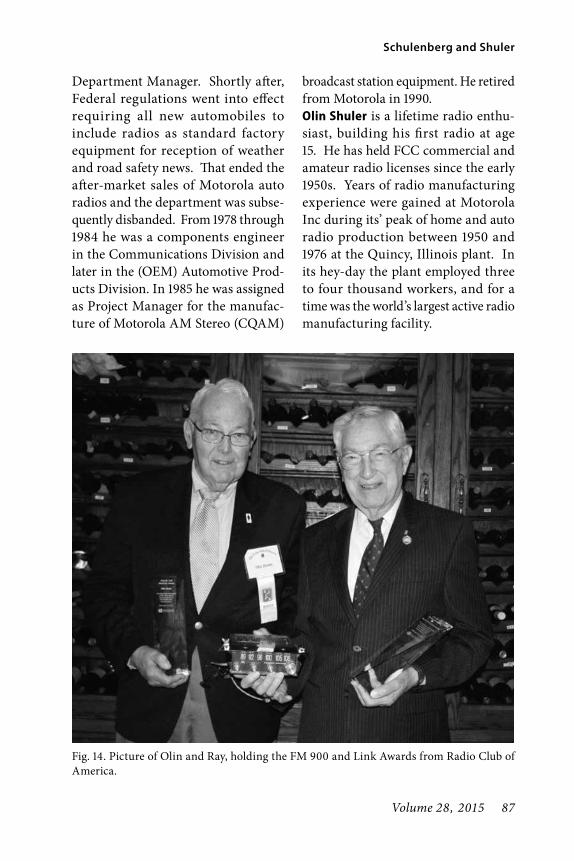
Volume 28, 2015 87
Schulenberg and Shuler
Department Manager. Shortly after, Federal regulations went into effect requiring all new automobiles to include radios as standard factory equipment for reception of weather and road safety news. That ended the after-market sales of Motorola auto radios and the department was subse-quently disbanded. From 1978 through 1984 he was a components engineer in the Communications Division and later in the (OEM) Automotive Prod-ucts Division. In 1985 he was assigned as Project Manager for the manufac-ture of Motorola AM Stereo (CQAM)
broadcast station equipment. He retired from Motorola in 1990.Olin Shuler is a lifetime radio enthu-siast, building his first radio at age 15. He has held FCC commercial and amateur radio licenses since the early 1950s. Years of radio manufacturing experience were gained at Motorola Inc during its’ peak of home and auto radio production between 1950 and 1976 at the Quincy, Illinois plant. In its hey-day the plant employed three to four thousand workers, and for a time was the world’s largest active radio manufacturing facility.
Fig. 14. Picture of Olin and Ray, holding the FM 900 and Link Awards from Radio Club of America.

88 The AWA Review
The First Broad cast FM Auto Radio—Motorola FM-900
There Motorola introduced many new products such as: transistor pow-ered “hybrid” (tube and transistor) car radios; shirt pocket transistor portables; the FM car radio; solid-state car radios; “Vibrasonic Sound”—reverb for car radio rear deck speakers; three channel stereo phonographs using a center bass channel; its’ first electronic ignition sys-tem; solid state home radios; FM stereo; the eight track stereo tape player; home quadraphonic surround-sound using a modified 8 track tape player; the early 1970s car entertainment center, a com-bined AM-FM stereo 8 track player, and an interlude with manufacture of the ill-fated CBS electronic video record player, the EVR.
As a production engineer, and later the department manager, he and his staff served as technical interface
between design engineering in Frank-lin Park, IL and the Quincy plant, 300 miles distant. The department was responsible for technology transfer and provision of ongoing support, perform-ing services nowadays defined as that of a Quality Engineer. Each new project brought learning opportunities for the people in a plant producing an increas-ingly diversified product line.
Today, Olin Shuler is a retired Reg-istered Professional Quality Engineer (California License QE-5694), and a Fellow in the American Society For Quality, (ASQ). He is the immediate past-president of the Antique Radio Club of Illinois, 2014 recipient of the Radio Club of America, Link Award, and active in six antique radio organi-zations including AWA.

Volume 28, 2015 89
Arvin Metal Cabinet Radios©2015 Dan Howard
AbstractNoblitt-Sparks Industries of Columbus, Indiana, began producing radios for home use in 1934. After leaving Atwater Kent in 1936, Albert D. “Duke” Silva joined the company and helped reshape the product line. Radios in drawn metal cabinets, were introduced in 1938 and remained the company’s low-cost offering until the mid-1950s. In 1950, the company changed its name to “Arvin Industries” honoring the trademark under which it had sold auto parts and consumer goods since the 1920s. In addition to marketing radios under its own Arvin brand, Noblitt-Sparks was among those making Silvertone brand radios for Sears, and also sold radios under various other private brands both in the United States and Canada. Products included a Walt Disney-licensed promotional model for the animated feature Pinocchio, and the very famous Hopalong Cassidy radio.
IntroductionWhen our local antique radio club was founded in 1974, battery operated radios, crystal sets, and horn speakers were at the forefront of collecting inter-est. Eventually, cathedrals, early AC radios, and consoles became accepted as collectables. Radios made after The Depression continued to be largely ignored.
Some in the collecting community finally discovered Arvin’s metal cabinet radios in the late 1980s after chromed versions appeared in Philip Collins’s Radios: The Golden Age. About that time I decided that a compendium with accurate model numbers, produc-tion dates, lists of original colors, and pictures of unaltered sets would help
collectors embrace the sets and provide a worthwhile reference for the future. Since the first version was published in Antique Radio Classified in January 1993, enough additional information and exciting new discoveries have come along to warrant a complete rewrite, this time with color photography.
Collectors and decorators seek Arvins for their eye-catching colors and designs. Big beautiful consoles will always have their place. But a single bookshelf may be large enough to display a whole collection of the tiny Arvins. And a single set makes a great accent piece just about anywhere.
Some may not be aware that, in addition to selling radios under its own brand name, Arvin sold many of

90 The AWA Review
Arvin Metal Cabinet Radios
its models under a variety of “private labels.” The “other” Arvins and collect-able accessories are covered in parts VII and VIII of this article.
Following is a model-by-model pre-sentation of the Arvin Metal Cabinet Radios.
Part I: About ArvinQuintin G. “QG” Noblitt, Frank Sparks, and Albert “Al” Redmond formed the Indianapolis Air Pump Company on January 1, 1919 (Coons, 4). Tire pump sales soon made the company profitable.
In the fall of 1920, Richard H. Arvin interested the partners in a heater design he had been developing for Ford automobiles (Coons, 34). Their exper-tise in fabricating tubing and stamped-metal products made manufacturing the Arvin heaters, car mufflers, and a wide variety of other auto parts, a natural fit for the company.
On December 29, 1927, the com-pany changed its name to Noblitt-Sparks Industries Inc. (Coons, 92). Then, after many years of promoting products under the Arvin trademark, they changed their name officially to Arvin Industries, Inc. on July 5, 1950 (Coons, 37). At the time, Arvin’s radio production volume ranked it among the largest producers in the county (Coons, 184).
Part II: Prewar Radios1938–1939Noblitt-Sparks entered the radio mar-ket in March, 1933, manufacturing
Arvin-brand after-market car radios. Arvin car radios were purchased by car owners that wanted to upgrade or add a radio to a car that was sold without one. They left the car radio market in 1941 when more cars were coming with radios as standard equipment.
Noblitt-Sparks began producing Arvin home radios in wooden cabi-nets in 1935. When Atwater Kent closed business in 1936, Albert DeVere “Duke” Silva, the company’s chief engineer, came to Noblitt-Sparks. Mr. Silva is generally given credit for expanding the home radio product line in the late thirties, including the introduction of metal cabinet sets.
Atwater Kent had been producing stamped steel radio cabinets and radio parts at its plant in Philadelphia since the 1920s. Shortly after his arrival at Noblitt-Sparks, Mr. Silva was able to bring tooling from the closed plant to their manufacturing facilities in Indi-ana. With the new tooling and know-how, Noblitt-Sparks added radios in economical metal cabinets to their already successful line of wooden radios.
In a gesture of appreciation to his old friend, Duke Silva sent one of the two-tube Arvin Model 40s to A. Atwa-ter Kent. In a 1939 letter of appreciation, Mr. Kent wrote,
“I cannot thank you enough for the beautiful little radio that you sent me. It is certainly a marvel in volume, tone, and selectiv-ity…I appreciate so much your

Volume 28, 2015 91
Howard
thought of me and letting me see what marvelous results can be obtained from such a small instrument.” (Silva, 9)
I’m only speculating here, but I do wonder if the choice to designate the first metal Arvin the “Model 40” was in any way a nod to Atwater Kent’s very-successful metal cabinet set by the same name.
During the earliest production years, Noblitt-Sparks offered metal cab-inet radios with two, three, or five tubes and a four-tube radio-phonograph. By 1940, they had trimmed the line to just four or five tube circuits.
The first three models, (40, 302, and 402) used TRF (tuned radio frequency) circuits. After that, all models used superheterodyne circuits.
Fig. 1. Model 40 & 40A.
“The mighty Arvin Arvinet”
The two-tube Model 40 (chassis RE-49) was one of the company’s earli-est offerings. As shown in Figure 1, its distinctive features include a key-hole shaped dial plate, bar-shaped pointer knob, and ridge running front-to-back above the dial. Like several other mod-els, the Model 40 featured a paper-backed foil dial.
Noblitt-Sparks offered a suede carrying case for the Model 40, for $1.00 more.
Model 40s have been found with two different names, “Arvin” and “Mighty Mite,” and there is at least one privately-labeled version, the Lafayette. According to various sources, overall sales of the little set exceeded 100,000 units.
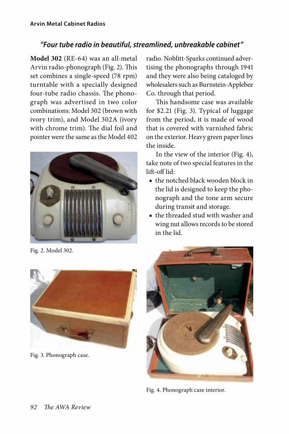
92 The AWA Review
Arvin Metal Cabinet Radios
“Four tube radio in beautiful, streamlined, unbreakable cabinet”
Model 302 (RE-64) was an all-metal Arvin radio-phonograph (Fig. 2). This set combines a single-speed (78 rpm) turntable with a specially designed four-tube radio chassis. The phono-graph was advertised in two color combinations: Model 302 (brown with ivory trim), and Model 302A (ivory with chrome trim). The dial foil and pointer were the same as the Model 402
radio. Noblitt-Sparks continued adver-tising the phonographs through 1941 and they were also being cataloged by wholesalers such as Burnstein-Applebee Co. through that period.
This handsome case was available for $2.21 (Fig. 3). Typical of luggage from the period, it is made of wood that is covered with varnished fabric on the exterior. Heavy green paper lines the inside.
In the view of the interior (Fig. 4), take note of two special features in the lift-off lid:
■ the notched black wooden block in the lid is designed to keep the pho-nograph and the tone arm secure during transit and storage.
■ the threaded stud with washer and wing nut allows records to be stored in the lid.
Fig. 4. Phonograph case interior.
Fig. 3. Phonograph case.
Fig. 2. Model 302.
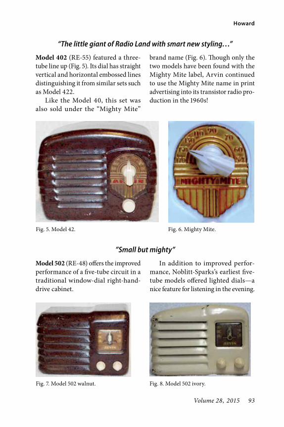
Volume 28, 2015 93
Howard
Model 402 (RE-55) featured a three-tube line up (Fig. 5). Its dial has straight vertical and horizontal embossed lines distinguishing it from similar sets such as Model 422.
Like the Model 40, this set was also sold under the “Mighty Mite”
brand name (Fig. 6). Though only the two models have been found with the Mighty Mite label, Arvin continued to use the Mighty Mite name in print advertising into its transistor radio pro-duction in the 1960s!
Fig. 5. Model 42.
Fig. 7. Model 502 walnut.
Fig. 6. Mighty Mite.
Fig. 8. Model 502 ivory.
“The little giant of Radio Land with smart new styling…”
”Small but mighty”
Model 502 (RE-48) offers the improved performance of a five-tube circuit in a traditional window-dial right-hand-drive cabinet.
In addition to improved perfor-mance, Noblitt-Sparks’s earliest five-tube models offered lighted dials—a nice feature for listening in the evening.

94 The AWA Review
Arvin Metal Cabinet Radios
All Model 502 cabinets have a raised hump on top. As shown in Figure 7, early production cabinets are nearly
flat; later sets feature a rounded top like most other Arvins (Fig. 8).
The 502 came with a 3/4-height vented metal back.
1940–1941
“So small, it tucks away in overnight luggage— so attractive, it wins admiration from everyone who sees it—
so efficient, it surprises everyone who hears it.”
1940 brought a new “Arvinet,” Model 422 (RE-91) featuring a new four-tube chassis in the old three-tube Model 402 cabinet. The restyled dial displays curved accent lines instead of straight (Fig. 9).
Fig. 9. Model 422.
Fig. 10. Model 522.
“Five tube super compact.”
Model 522 (RE-76) was an updated five-tube model. While retaining the window-style cabinet, the redesign moved the hump to the center, giv-ing the top a more symmetrical look than the 502 (Fig. 10). The 522 had a lithographed dial face with prominent vertical stripes and the word “ARVIN” above the pointer.
The 522s came with a ventilated fiberboard back that contained a loop antenna and stuck out about an inch behind the cabinet.

Volume 28, 2015 95
Howard
“Extremely powerful as well as selective…”
Fig. 11. Model 524.
Model 524 (RE-99) shares the same window-dial cabinet with Model 522 but several changes were made between the models including a different five-tube chassis and dial face (Fig. 11).
The newer model has a foil-backed paper dial with the word “ARVIN” printed below the pointer. Reflecting cost-saving measures, the dial is not lighted, the set uses a wire antenna instead of the 522’s loop, and no back cover was provided.
Part III: World War IINoblitt-Sparks continued to make some civilian products during 1941, even as more government contracts began to come in. However, “materials for auto-motive parts, automobile heaters, and radios became increasing difficult to obtain because of priorities established by the government for strategic materi-als.” (Coons, 156).
By the end of 1942, all civilian pro-duction had ceased as Noblitt-Sparks staffed-up to fulfill contracts for various material including:
■ communications reels ■ jerry cans ■ fire extinguishers ■ bomb casings ■ tail pipes for army vehicles ■ Jeep fittings (Coons, 49)
Civilian production resumed in August, 1945, and by the end of the year Noblitt-Sparks was again mak-ing automotive parts, car heaters, home radios, metal furniture, dinette sets, and all-metal ironing tables (Coons, 163).
Duke Silva, the former Atwater Kent engineer, left Noblitt-Sparks in 1945 to form his own company, Columbia Pro-cess Company (later CP Electronics), in Columbus, Indiana. In addition to contracting with the military, the com-pany soon became a major supplier of transformers (Coons, 126).
Part IV: The mid-1940sAfter converting back to civilian production following World War II, Noblitt-Sparks presented its first new metal cabinet radios in 1946. Though the sets didn’t change much stylisti-cally at first, there were two significant changes when production resumed: color and tubes.
■ In contrast to the prewar brown and ivory cabinets, color variety soon became a major selling point.
■ Noblitt-Sparks continued to offer a variety of tube line ups in its other postwar models, but all postwar metal cabinet sets used four-tube chassis.

96 The AWA Review
Arvin Metal Cabinet Radios
1946“Tiny, but terrific”
The first postwar metal radio, Model 444 (RE-200), is pictured in Figure 12. Like the 1940–1941 models, Model 444 was originally offered only in brown (Model 444) and ivory (Model 444A). Then, in 1948, they began offering Model 444 in six bright new colors – a first for the line.
Four of the new colors used painted foil dials—a feature unique to this model. Leaf green, persimmon, and turquoise cabinets have white-dials and banana yellow cabinets have blue-painted dials. Gardenia cream (light green) and geranium red cabinets had unpainted bronze-colored dials, but used black knobs; the other colors used standard ivory.
Cabinets originally came with vented metal backs painted in match-ing colors.
A handled version, the Model 444AH (RE-200), features a black plas-tic handle and matching black knobs.
The cabinet top is specially-embossed with raised flats where it is joined to the handle. I have seen this set in ivory and turquoise, so I assume that it was avail-able in other colors as well. The example shown in Figure 13 was originally ivory and badly in need of restoration. So, I repainted it red to add variety.
Models 445 & 445A (RE-200) were Arvins with special labeling that were sold in Canada. Examples I’ve seen have a paper manufacturer’s label on the back cover along with the Canadian Standards Association approval decal. Unlike some other Canadian examples, this model lists the Columbus, Indiana, plant as the place of manufacture.
The 445s used the same RE-200 chassis that the American Arvin 444s did, so there is not much difference, other than the labeling. Although they may have been made in other colors, so far I’ve only seen a brown 445 and an ivory 445A.
Fig. 12. Model 444 and 444A.

Volume 28, 2015 97
Howard
1947In 1947 Noblitt-Sparks created a ver-sion of Model 444 using the newly-available miniature tubes; Model 444M (RE-200M). Model 444M is brown and Model 444AM is ivory. After these models, they didn’t use miniature tubes in metal radios again until the Fifties.
I don’t know if they were all made this way but, you can see in Figure 14, that this RE-200M chassis was punched for octal tube sockets (like an RE-200). Flat bushings were riveted-in to hold the smaller sockets for miniature tubes.
Although it was first produced in 1947, Model 442 (RE-91), (Fig. 15), is actually a prewar design. Style-wise, the cabinet, dial, and knobs are identical to the prewar Model 402 (Fig. 5). And its RE-91 chassis was used in the Model 422 (Fig. 9)
Despite its clear prewar roots, print ads and production dates on known examples confirm the set’s production in the late 1940s.
Original examples have beautiful Ebony (black) paint and a special silver
dial face with black printing. Except for the black version of the Hopalong Cassidy radio, this color combination was only used on this model. And the 442 has not been reported in any other colors.
A final point about the set—Model 442 was the last in the series to use a foil dial with a pointer knob. T-series models used a large tuning knob with the dial scale on it.
Fig. 13. Model 444AH. Fig. 14. Model 444AM.
Fig. 15. Model 442.

98 The AWA Review
Arvin Metal Cabinet Radios
Part V: The T-Series setsIn 1948 Noblitt-Sparks revised its model numbering scheme and cre-ated the “T-Series” sets; all sets having model numbers ending in the letter “T.”
The first T-Series sets were a con-tinuation of the company’s line of small
metal cabinets. In 1950, they changed over to the large brick-shaped cabinets they stayed with through the end of production.
During the years the T-Series sets were produced, model numbers consis-tently ran in sequence, increasing from 242T through 842T.
1948
“Choice of smart colors”
Model 242T/243T/343T (RE-251) marked the change from using dial foils and pointers to large tuning knobs (Fig. 16). And Noblitt-Sparks used the opportunity to create terrific color com-binations for its new model (Fig. 17).
Color combinations include: ■ sand brown with brown knobs, ■ leaf green with banana yellow knobs,
■ gunmetal (gray) with light gray, ■ ivory with light tan, ■ fox hunt red with pale yellow, ■ citron yellow with light blue knobs.
Noblitt-Sparks called the ivory cabinet “Model 242T” and the other
Fig. 16. Model 242T. Fig. 17. Model 243T.

Volume 28, 2015 99
Howard
colors were designated 243T. In all other respects they are the same.
Some print advertising at the time nicknamed the model the “Keen Teen” radio, clearly aiming for the youth mar-ket. At $14.95 it had “a price that won’t bother Father” (Seventeen, 32).
Two different types of plastic were used to make the tuning and off/on knobs. The tuning knob is a harder plastic like styrene. The off-on/volume control knob is a softer vinyl-type plas-tic. So, you may find that your knob colors no longer match exactly due to the way the plastics have aged.
The 343T version of the 243T was created for the Canadian market. The
back cover bears the Canadian Stan-dards Association approval decal as well as a decal from Deseronto Elec-tronics Limited, an Ontario company. The larger paper label also asserts that the set was made in Canada by Dese-ronto Electronics Limited.
I’ve seen343Ts in red cabinets and green, so I assume that they came in some or all of the same combinations as the 243T. Both sets I’ve examined had standard Arvin knobs and are identical to the 243T’s except for the labeling.
1948 also saw the start of Noblitt-Sparks’s short-lived production of televisions. See Part VIII for more information.
Fig. 18. Model 241T.
1949
“Shatterproof, kidproof—perfect for children, for dormitory, hospital, or hotel use”
Model 341T (RE-274) (Fig. 18) is the last of the small-format sets. Although it used a unique new chassis, its other components were likely the product of tooling from earlier production:
■ cabinet - Models 402/422/442 ■ maroon tuning knob - Model 242T ■ skirted off/on knob - Model 444.
Dubbed, “The Bantam,” it was only available in the sandalwood (light tan) paint with maroon knobs combination.
1950In 1950, Arvin began marketing sets in large-format (brick-shaped) cabinets. Despite the larger chassis, Arvin stuck with the four-tube circuits from the earlier smaller sets. All the large-format
sets are about the same size with differ-ent styles of speaker grills. Most sets in the series were provided with unvented sheet metal backs painted to match the cabinet.

100 The AWA Review
Arvin Metal Cabinet Radios
You may occasionally see small paper tags with serial numbers on the bottom of some of the later production sets, such as the 740T. I’ve not made an
effort to study the numbers or account for them. I’ll leave that to collectors with access to larger samples.
“Color accent for any room”
A globe-style speaker makes Model 440T (RE-278), stylish and easy to rec-ognize (Fig. 19). The new design was named “The Velvet Voice” and print advertising included a double-V logo (Fig. 20), although the radio itself was not so marked.
Model 440T was produced in a vari-ety of colors including banana yellow, burgundy, fox hunt red, ivory, sand bronze, and willow green. Versions of its RE-278 chassis are used in all of the later sets in the series.
Fig. 19. Model 440T. Fig. 20. Velvet Voice.
“You’ve got a real range ridin’ radio”
Model 441T (RE-278), is the well-known Hopalong Cassidy radio (Fig. 21). Certainly the most flamboy-ant radio in the series, it is none-the-less based on the traditional metal cabinet and four-tube RE-278 chassis. Arvin was licensed January 28, 1950 (Rinker, 142), to produce the radios as promo-tional items available to fans of Hoppy’s many ventures – radio, television, mov-ies, and books.
The set came in two colors—red and black. And each color was available with one of two different dial faces—one featured Topper standing, and the other featured Topper rearing. So, there are as many as four different variations to collect.
Besides the celebrity tie-in, Arvin incorporated several model-specific features into the set:

Volume 28, 2015 101
Howard
■ Chrome knob centers—only seen on this set and 542T (Fig. 24)
■ A special back cover (Fig. 22) with an embossed saddle and punched out pommel for hanging the “Lariatenna”
■ Model 441T is the only large-format cabinet that incorporated embossed foil decoration, and the only set whose whole front was covered in embossed foil.Arvin didn’t miss a bet with this set,
even packing it in a special box deco-rated to match the scene on the front
of the radio. I’m sure that just the sight of the box as it emerged from wrapping paper at a birthday party was enough to elicit squeals of delight.
Fig. 22. Model 441T back.
Fig. 23. Model 540T.
Fig. 21. Model 441T.
1951
“Tops for tone and color”
Model 540T (RE-278) was available in avocado, cherry (pink), citron (lemon yellow), flame (red) (Fig. 23), ivory, and pebble (gray). Arvin used a separate plastic name plate for the first time with this model, leaving the knobs plain. This change facilitated sales of 540T’s under various private labels.
In the mid 1950s, Arvin reused the 540T cabinet twice to create additional models—see below.
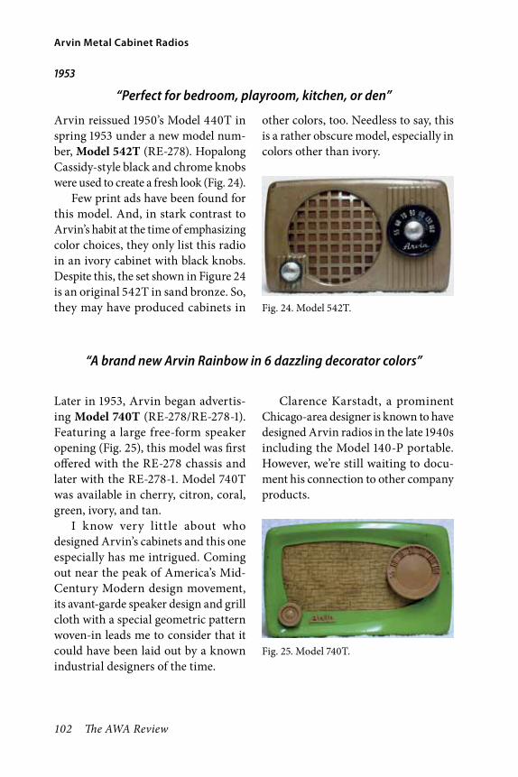
102 The AWA Review
Arvin Metal Cabinet Radios
1953
“Perfect for bedroom, playroom, kitchen, or den”
Arvin reissued 1950’s Model 440T in spring 1953 under a new model num-ber, Model 542T (RE-278). Hopalong Cassidy- style black and chrome knobs were used to create a fresh look (Fig. 24).
Few print ads have been found for this model. And, in stark contrast to Arvin’s habit at the time of emphasizing color choices, they only list this radio in an ivory cabinet with black knobs. Despite this, the set shown in Figure 24 is an original 542T in sand bronze. So, they may have produced cabinets in Fig. 24. Model 542T.
other colors, too. Needless to say, this is a rather obscure model, especially in colors other than ivory.
“A brand new Arvin Rainbow in 6 dazzling decorator colors”
Later in 1953, Arvin began advertis-ing Model 740T (RE-278/RE-278-1). Featuring a large free-form speaker opening (Fig. 25), this model was first offered with the RE-278 chassis and later with the RE-278-1. Model 740T was available in cherry, citron, coral, green, ivory, and tan.
I know very little about who designed Arvin’s cabinets and this one especially has me intrigued. Coming out near the peak of America’s Mid-Century Modern design movement, its avant-garde speaker design and grill cloth with a special geometric pattern woven-in leads me to consider that it could have been laid out by a known industrial designers of the time.
Clarence Karstadt, a prominent Chicago-area designer is known to have designed Arvin radios in the late 1940s including the Model 140-P portable. However, we’re still waiting to docu-ment his connection to other company products.
Fig. 25. Model 740T.

Volume 28, 2015 103
Howard
1954
“A color to match any room in the house. Perfect for small fry, with a non-breakable cabinet that welcomes abuse”
Fig. 26. Model 840T. Fig. 27. Model 842T.
I believe that Model 840T (RE-278-1) was issued with the “-1” chassis from the start, giving us some indication of about when the improved chassis came out. (Other models were first issued with the 278 chassis, and the -1 chassis was used for later production).
The front features a stylish speaker design with vertical grill bars and an arrow-shaped name plate (Fig. 26). The name plate also serves as a dial pointer; the frequency is read at the left side of the tuning knob where it touches the pointer rather than at the top as on most radios. No chassis modifications
were required; Arvin simply shifted the dial scale on the knob counter-clockwise 90 degrees! Listed in ads as Arvin’s “Rainbow,” Model 840T came in colors very similar to Model 740T: cherry, citron, coral, bitter green, ivory, and sandalwood.
The Model 540T cabinet was reused in 1954 when Arvin paired it with the improved RE-278-1 chassis and released it in ivory as Model 842T (RE-278-1). Apart from the new chassis and model number, it was unchanged from the 1951 models (Fig. 27).
Final ProductionArvin’s last metal cabinet radios were reissues of the Model 840T and Model 842T (Fig. 28) with the miniature-tube RE-278-2 chassis. They were not given new model numbers.
I don’t have an exact time frame for this production but have to assume that they came out about 1955. Since they
don’t have unique model numbers, and are identical from the outside to earlier production, you really have to see the sets from the back to identify them.
On September 15, 1954, Arvin’s 4 millionth 4-tube radio, a coral pink Model 740T, came off the assembly line (Coons, 187). At that point the line had spanned more than 15 years

104 The AWA Review
Arvin Metal Cabinet Radios
of production and, as shown here, a myriad of designs. By 1956, when the Arvin’s first all-transistor radio came out, both the company’s short-lived television line, and its metal-cabinet radios were things of the past.
Part VI: Metal Silvertone RadiosMany collectors are familiar with the “Silvertone” brand radios that Arvin produced for Sears, Roebuck, and Co. Since all Silvertone radios were made by outside manufacturers, Sears used the first three digits of the chassis number to indicate the source. Arvin’s source number was 132. Look for the chassis number on the back of the chassis and the catalog number on the bottom label.
1940 Silvertone Catalog No. 5741 (132.808)The fall 1940 Sears Catalog listed the Silvertone version of the Arvin Model 302 metal cabinet radio-phonograph (Fig. 29). Although the two versions are very similar, there are notable differences.
1. The Sears version used an all-brown cabinet with light brown knobs. The Arvin version came in white with a chrome grill or brown with a white grill. Gone are the Arvin’s body lines on the sides.
2. Perhaps in a cost-savings measure, the Sears version used a horizontal louvered speaker opening that was part of the cabinet. The 302 used a separate grill with vertical bars.
3. The Sears version also used special knobs that are styled differently from any that were used on Arvin-branded sets.
In an effort to estimate the pro-duction period for the 5741, I checked catalogs before and after Fall 1940 and believe that it was only listed for sale the one time.
1942 Silvertone Catalog No. 7020 and 7022 (132.814)In early 1939, Noblitt-Sparks began producing a 5-tube radio in a Bakelite case for Sears called “The Commenta-tor.” When plastics became scarce in the early 1940s due to wartime short-ages they created a metal version. Sears spring 1942 catalog lists the set in two colors.
No. 7020 (Fig. 30) has walnut paint (brown with black flecks) and gold trim and knobs. No. 7022 has ivory paint and is trimmed in red, a nice combina-tion (Fig. 31).
The bakelite and plastic versions of the Commentator had an internal coil antenna. Since the metal cabinet would shield an internal antenna, the Fig. 29. Silvertone 5741.

Volume 28, 2015 105
Howard
designers added the 1-1/2” high open-bottom pedestal base to contain the Faraday loop antenna for better recep-tion (Isenring, 11).
7020 and 7022 were only available briefly before civilian radio produc-tion ceased, and were only advertised in 1942.
Postwar production of the Bakelite version of The Commentator resumed August 20, 1945, just six days after President Truman’s victory announce-ment (Coons, 163). In 1980, Eugene I. Anderson, the president of Arvin, pre-sented a Commentator to the president of Sear, Roebuck and Co. in honor of the 40-year relationship between the companies (Coons, 156).
1946 Silvertone Catalog No. 6002 (132.818)The first postwar model, the Silver-tone “Midget” No. 6002 (Fig. 32) was similar in size and design to the Arvin Model 444. The word “Silvertone” was embossed on the top front of the cabi-net and filled with red paint to match the dial scale and complement the ivory cabinet. 6002 came with a unique vented metal back (Fig. 33) that has “ears” on the corners for coiling up its wire antenna.
Fig. 30. Silvertone 7020.
Fig. 31. Silvertone 7022.
Fig. 32. Silvertone 6002.
Fig. 33. Silvertone 6002 back.

106 The AWA Review
Arvin Metal Cabinet Radios
1948 Silvertone Catalog No. 8003 (132.818-1)In 1948, Sears began cataloging No. 8003 which was simply a restyled 6002 with “gray-green” (light blue) paint; (Figures 34 and 35).
Changes included moving the word “Silvertone” from the cabinet onto the dial, and eliminating the vented metal back.
1949 Silvertone Catalog No. 8004 (132.818-1)In 1949, No. 8004 with ivory paint was first cataloged.
As was typical for many models, the ivory 8004 (Fig. 36) retailed for two dollars more than the identical 8003 in gray-green.
1950 Silvertone Catalog No. 1 & 2 (132.878)Silvertones from the 1950s reflect the same manufacturing changes that Arvin implemented for its own sets at the time:
■ Cabinets became larger but kept the same 4-tube circuits.
■ Dial foils and pointer knobs were replaced with knobs with embossed dial scales.The Silvertone No. 1 (brown with
ivory knobs) and No. 2 (ivory with maroon knobs), are the most commonly found private label Arvins – Sears must have sold a lot of them (Fig. 37).
These models feature a unique tun-ing arrangement—the tuning knob is captive inside the cabinet and is oper-ated through a small hole.
Fig. 34. Silvertone 8003 box.
Fig. 35. Silvertone 8003.
Fig. 36. Silvertone 8004.

Volume 28, 2015 107
Howard
Fig. 37. Silvertone 1 & 2.
Fig. 38. Silvertone 2001 & 2002.
1953 Silvertone Catalog No. 2001 and 2002 (132.878)In 1953, Sears stopped cataloging Mod-els 1 and 2 and offered two new models. As shown in Figure 38, the new radios, No. 2001 (brown with ivory knobs) and No. 2002 (ivory with tan knobs), fea-ture distinctive cross-hatched speaker grills.
Part VII: Other Private Label ProductionIn addition to the sets sold through Sears under the Silvertone brand, Arvin sold some of it sets under other pri-vate labels for the US and Canadian markets.
Two brands, Firestone and Fleet-wood, were produced in the 1950s. The other privately-labeled sets were all ver-sions of Arvin’s prewar models.
FirestoneIn 1955, Arvin sold the Model 840T under the Firestone brand name (Fig-ures 39 and 40). Firestone called it the Model 4-A-124 “Newscaster.” Firestone sets were retailed through the Firestone Tire and Rubber stores and were just one of the many types of radios sold by the company.
The Firestone’s bottom label gives the stock number as 4-A-124 and a “Code Number” of 382-4-278/1. The

108 The AWA Review
Arvin Metal Cabinet Radios
back of the chassis has Arvin’s standard RE-278-1 oval tag.
It’s likely that the code number ref-erences the 278-1 chassis and “382” may have been Firestone’s manufacture’s code for Arvin.
To date, sets have only been seen in olive green and red (both with the standard tan knobs).
Due to its poor condition, this example was repainted and received replacement grill cloth prior to being photographed.
FleetwoodElectrical Products Manufacturing Co LTD of Montreal, QC, made sets similar to the Arvin 540T under the Fleetwood brand (Figures 41 and 42). Unlike Arvins, Fleetwood chassis have
metal maker’s tags with unique serial numbers. To date, I’ve seen Fleetwood Model 53-53 radios in maroon, ham-mertone brown, and white. Besides paint color, variations include decals in place of the usual plastic name badges.
Similar Canadian sets may have been found under the “Serenader” brand name as well. However, I’ve not been able to confirm the details.
KentI have seen two different Arvins with the “Kent” brand name. The first is a three-tube Model 402A (Fig. 43). The second is a four-tube Model 422A (Fig. 44). Except for the name on the dial foil, the Kent Model 402A is identi-cal to the Arvin version.
The Kent Model 422A, however, has a black plastic carrying handle and
Fig. 39. Firestone Newcaster. Fig. 41. Fleetwood.
Fig. 42. Fleetwood back.Fig. 40. Firestone logo.

Volume 28, 2015 109
Howard
black, rather than ivory, knobs. This is the only radio, besides the 444AH to come with a handle.
LafayetteThe two-tube Arvin Model 40 was privately labeled under the Lafayette brand name (Figures 45–47). I’ve seen examples in Walnut (model W45) and Ivory (model W46), just like the Arvins.
The labeling doesn’t acknowledge Noblitt-Sparks in any way and instead mentions “Wholesale Radio Service Co, Inc.” Print ads from the 1930s reveal that the company was a New York City retailer that published the “Lafayette
Fig. 43. Kent 402. Fig. 45. Lafayette.
Fig. 46. Lafayette logo.
Fig. 47. Lafayette box.
Fig. 44. Kent 422.

110 The AWA Review
Arvin Metal Cabinet Radios
Radio catalog.” The company changed its name to “Radio Wire Television, Inc.” in 1940, so this pretty well dates sales of the sets to the late 1930s.
The Lafayette’s paper label is pasted inside the top as was Noblitt-Spark’s practice at the time.
MidwestNoblitt-Sparks also produced its Mod-els 402 and 422 under the Midwest brand name (Figures 48 and 49).
The Midwest Radio Corporation of Cincinnati, OH, was known for manu-facturing large elaborate console radios in the 1930s and 1940s. In 1941, these sets were given free with purchase of
Midwest’s most-deluxe 12- and 18-tube console models. Buy a nice console for your living room and get a free radio for somewhere else in the house!
Powertone 402AWalt Disney studios entered into a licensing agreement with Noblitt-Sparks to produce radios from 1938 to 1941 (Tumbusch, 61). Until recently Disney collectors had not been able to determine what, if any, radios were pro-duced based on that agreement. Today, collectors believe that the contract was for the Powertone Pinocchio radio (Fig-ures 50 and 51).
RKO Radio Pictures released Dis-ney’s Pinocchio, on February 7, 1940. Newspaper ads at the time announced that theatres were holding drawings for movie goers with radios as the prize.
Besides the unique “Powertone” dial plate, the Powertone version of the 402As were decorated with nine WDP (Walt Disney Production) Pinocchio decals.
Fig. 49. Midwest 422.
Fig. 50. Powertone 402A.
Fig. 48. Midwest 402.

Volume 28, 2015 111
Howard
All Powertones examined to date are ivory and have the same set of decals in identical locations.
Well worth the price of admission, then and now.
Part VIII: AccessoriesArvin and others made several items that are natural extensions of a collec-tion of metal cabinet sets.
Imperial Radio CruiserUsing the RE-200 chassis from Arvin’s Model 444 radio, Mastercrafters Manufacturing Company of Chicago produced the Imperial Radio Cruiser Model 029 ship radios in the late 1940s (Figures 52 and 53). Earlier, Master-crafters cooperated with Majestic to produce the Melody Cruiser ship novelty radios. They also made many varieties of electric clocks. While not strictly a metal cabinet radio, I felt that its use of the Arvin chassis (and
its outstanding looks) qualified the Radio Cruiser for inclusion.
Ivalek Crystal SetIn the 1950s, Ivory Electric Ltd (Lon-don, England) produced an “Ivalek” crystal set made in the shape of an Arvin Model 444A (Figure 54). The cabinet is unpainted white plaskon with a white dial scale and a black tuning knob. Overall, the set measures 4.75” wide, 3.5” high, and 2.5” deep. As was typical for the time, a diode is used for detection. Binding post connections are provided on the back for earphones, aerial, and “earth” (ground).
The company made second ver-sion that used a cat’s whisker detector
Fig. 51. Powertone logo.
Fig. 52. Radio Cruiser.
Fig. 53. Anchor detail.

112 The AWA Review
Arvin Metal Cabinet Radios
instead of the diode. In that case, the handle for adjusting the detector was placed where the off/on knob would go—making it even more similar to the Arvin 444A. Although the cabinets all seem to be white, the cat’s whisker ver-sions have black dials with white letter-ing (the reverse of the diode versions). And I’ve seen pictures of red knobs and blue knobs for adjusting the detector, but not black—the obvious choice for matching the tuning knob.
Silvertone TransistorThis little AM-FM transistor Silver-tone is a very nice replica of the Model
6002 from 1946 (Fig. 55). The back says “Silvertone Mod. C-USA 1949—Min-iature.” I really appreciate their atten-tion to detail—even the knobs look like miniatures of the real thing. At 4.75” wide × 3.25” high × 1.75” deep, it’s roughly three quarters size. The set is a recent import from China and carries no manufacturer’s name.
Arvin Model 4080T TelevisionArvin only manufactured televisions under its own name for a short while (1948–1955) which coincided with the peak of their metal radio production.
After producing televisions in wooden cabinets for two years, in 1950 Arvin introduced the Model 4080T (TE-282) in a compact steel cabinet with an 8” picture tube (Fig 56). Even as their little metal-cabinet radios were their lower-priced offering, their metal-cabinet televisions were smaller and priced lower than their wooden sets and were marketed as “a perfect ‘sec-ond’ set.” Also, like they did with their metal radios, Arvin made the metal TV’s available in at least two different
Fig. 54. Ivalek.
Fig. 55. Silvertone transistor.

Volume 28, 2015 113
Howard
colors: limed oak and willow green. Ads for the set ran throughout 1950 in lead-ing magazines of the day including Life, Time, and The Saturday Evening Post.
Arvin promoted its televisions through the “Visible Value” campaign which paralleled the “Velvet Voice” radio promotion of the time (Fig. 57).
Part IX: NotesWere metal cabinets unique to Arvin?Obviously not. Wooden cabinets domi-nated the table radio markets of the 1920s and 1930s followed by Bakelite and other plastics. However, many companies besides Arvin produced radios for home use in metal cabinets.
For example: ■ Federal (DX58, Junior crystal set) ■ Crosley (Pup, Gembox, etc.) ■ Neutrowound (breadboards) ■ Atwater Kent (Model 35 battery set, Model 40 AC table set, Model 53 console, many more)Others too numerous to count
including RCA and Philco offered at least some models in metal cabinets.
Arvin was the exception by con-tinuing with metal into the mid 1950s by which point most other companies were converting mostly to plastics. Before World War II, metal was seen as an alternative to wood that offered consumers economy and additional styling choices. After World War II, consumer tastes had shifted, and metal was reserved mainly for appli-cations where it held an advantage over other materials such as portable radios (durability), coin-operated hotel radios (security), and novelties such as the Abbotwares horses (adaptability). And even those applications had largely faded by the early 1950s.
Arvin believed in metal because it was inexpensive to produce, lent itself to a variety of cabinet colors and styles, and offered travelers and families with children resiliency; advantages that the company regularly touted in advertising.
Fig. 56. 8040T ad.
Fig. 57. Visible Value.

114 The AWA Review
Arvin Metal Cabinet Radios
Although a few companies cast them, most companies formed their metal cabinets from one or more sheets of folded metal joined with welds. Arvin’s cabinets were stamped from a single sheet of steel, utilizing the same technology that they used to make heat-ers, mufflers, and other auto parts.
Look-alike radios were sold in 1948 and 1949 under the Ward’s Airline brand name, in a similar stamped-steel cabinet. The 84KR-1520A and 94KR-1520B sets were manufactured for Ward’s, but not by Noblitt-Sparks – significant differences in material and design make that obvious (Figures 58 and 59). By this time, Noblitt-Sparks was using superheterodyne circuits exclusively; this set is a TRF (tuned radio frequency) and uses ferrite rod
tuning (Bintliff, 7). Significantly, the Airline design, in a larger brick-shaped cabinet, reached the market two years before Arvin’s similar designs.
Paint ColorsBefore World War II, Arvin cabinets were only offered with ivory paint and one of two shades of brown. Except for the phonograph, models from 1938-1939 came in “walnut” brown with random black f lecks. Sets made in 1940–1941 came in plain brown. Ivory cabinets were designated with the letter “A” added behind the model number (like 402A).
Manufacturer’s Marks ■ Model Numbers: Like many manu-facturers, Arvin printed its model numbers on paper labels which were glued to the radio cabinets. Radios made before 1940 should have a label inside the top of the cabinet; on later models, look for a label on the bottom of the cabinet.
■ Production Dates: I’ve not seen production or inspection dates on prewar Arvins but they’re very common on postwar sets. Look for a production date code (AU 47 = August, 1947) rubber-stamped on the label of postwar sets.
■ Chassis Numbers: Because of their value in model identification and authentication, chassis numbers for each model are shown in parenthe-sis. Typically, the chassis number is stamped on the back of the chassis or on a small metal tag riveted on the back.
Fig. 58. Airline front.
Fig. 59. Airline back.

Volume 28, 2015 115
Howard
A final word about safetyOperating any of Arvin’s metal cabinet models can expose you to the danger of electric shock. Be sure to understand the hazards and exercise appropri-ate care, before plugging the sets in. Although this is true of most vintage radios, it is especially so with these transformerless all-metal sets.
ReferencesBintliff, Ray. “Radios with Permeability Tun-
ing – Part 1,” Antique Radio Classified Vol. 11 No. 8 August, 1994, pp. 6–9.
Coons, Coke. Arvin…The First Sixty Years, Arvin Industries Inc. Columbus, IN, 1982.
Duke University Library, Digital Collec-tions http://library.duke.edu/digital collections/adaccess_TV0039/
Isenring, Harold. “Sears Silvertone Commen-tator Radio,” Antique Radio Classified Vol. 13 No. 4 April, 1996, pp. 10–11.
“Noblitt-Sparks Ad,” Seventeen (magazine) August, 1948.
Rinker, Harry L. Hopalong Cassidy King of the Cowboy Merchandisers Schiffer Publishing. Atglen, PA, 1995.
Silva, Kevin Devere. “Arvin Metal Radios and A.D. Silva,” Antique Radio Clas-sified Vol. 10 No. 9 September, 1993, pp. 8–9.
Tumbusch, Tom. Tomart’s Illustrated Dis-neyana Catalog and Price Guide Vol 3., Tomart Publications. Dayton, OH, 1985.
Other Published Arvin Referenceshttp://AirChiefRadios.comArnold, Richard. “Arvin Industries and
the Hopalong Cassidy Radio – Part 2: Arvin Industries Model 441-T Hopalong
Cassidy Radio,” Antique Radio Classi-fied Vol. 6 No. 7, July, 1989, pp. 6–7.
Burnstein-Applebee Co. Radio and Electrical Catalog No. 57, 1941.
Goodwin, Bill and Dan Howard. “Arvin 402: The Powertone – Disney Link.” Radio Age Vol. 37 No. 6. June, 2012, pp. 5–7.
Gray, Jack. “Hopalong Cassidy; The Radio and the Actor,” Antique Radio Classified Vol. 24 No. 7, July, 2007, pp. 8–9.
Gray, Jack. “Vacuum Tube Ship Radios,” Antique Radio Classified Vol. 25 No. 10, October, 2008, pp 6–11.
Howard, Dan. “Arvin Metal Cabinet Radios,” Antique Radio Classified Vol. 10 No. 1, January, 1993, pp. 4–9.
http://www.ieeeghn.org/wiki/index.php/Albert_D._Silva
Jenson, Oliver. “Hopalong Hits the Jackpot,” Life June 12, 1950, pp. 63–70.
Lopes, Stan. “More on Metal Radios – A New Fad?” Antique Radio Classified Vol. 10 No. 6, June, 1993, pp. 8–9.
“The Postwar Radios – Arvin Model 444,” Radio-Craft Magazine, Sept., 1946, pg. 836.
Ruble, Larry and Fred Prohl. “Arvin Metal Radio 1939-1954,” The Indiana Histori-cal Radio Society Bulletin, Vol. 39 No. 3, Sept., 2010, pp. 18–27.
Seidel, Paul E. “Restoring a Sears Silvertone Commentator,” Antique Radio Classi-fied Vol. 15 No. 1, January, 1998, pp. 4–6.
Simpson, Mike www.midwestradiomuseum.com
Surkeck, William P. “Arvin Industries and the Hopalong Cassidy Radio – Part 1: A company History,” Antique Radio Clas-sified Vol. 6 No. 7, July, 1989, pp. 4–5.
Wood, Scott. Evolution of the Radio Vol. 1, L-W Book Sales, Gas City, IN, 1991.

116 The AWA Review
Arvin Metal Cabinet Radios
AcknowledgementsThe author gratefully acknowledges assistance provided by the following:Richard Bell, Lafayette, LASteve Berglund, Seattle, WABill Burkett, Sun City, AZBill Goodwin, Prince Frederick, MDLisa Howard, Jennings Lodge, ORRichard Howard, Happy Valley, ORJay Malkin, Denver, COFred Pohl, Nashville, INGene Pupo, Spokane, WACarl R. Shirley, Columbia, SCMike Schultz, Southampton, PAMike Simpson, Southern CaliforniaBill Timoszyk, Livonia, MI
Photo CreditsFigures 3 and 4 are courtesy of Bill Timoszyk. Other photography by the author of his collection. Section head-ers quoted from period Noblitt-Sparks advertising.
About the AuthorDan Howard lives just outside of Port-land, Oregon. Dan has been involved with his local antique radio club, The Northwest Vintage Radio Society, since its founding in 1974. Although he was not driving yet, Dan attended most of the meetings and all of the early swaps and shows, with his dad, Dick. Dan was honored to serve as society presi-dent in 1988 and 1989 and has written numerous articles for The Call Letter, the society’s monthly publication. More recently, Dan’s articles have appeared in Radio Age and The AWA Journal.
Dan has a passion for building displays and loves nothing more than
putting together a well-rounded display with historical documentation.
Radios have always been a pervasive theme in Dan’s life. After a shopping stop at the beach, the car ride home from a honeymoon trip was made a little more cramped by the Pilot AC Superwasp in a console cabinet jammed in the back seat of the two-door car.
Dan was first licensed as a ham radio operator in 1974 and was most active during high school and college, contact-ing all 50 states on 5 different bands.
Dan’s first “close encounter” with an Arvin metal radio occurred in the mid 1970s. A black Hopalong Cassidy was left behind at a local antique shop for $5 because it wasn’t considered “col-lectable” back then.
In addition to varied collecting interests in radio (from telegraph and wireless to novelty radios), Dan is espe-cially interested in antennas, including insulators and lightning arresters. A historian at heart, Dan published Old Familiar Strains, a bi-monthly newslet-ter devoted to the hobby of collecting radio antenna insulators, through the 1990s and early 2000s. Dan’s first visit to Rochester and the AWA reunion in 1999 included a fascinating tour of the Lapp Insulator factory in nearby LeRoy, NY.
Dan Howard
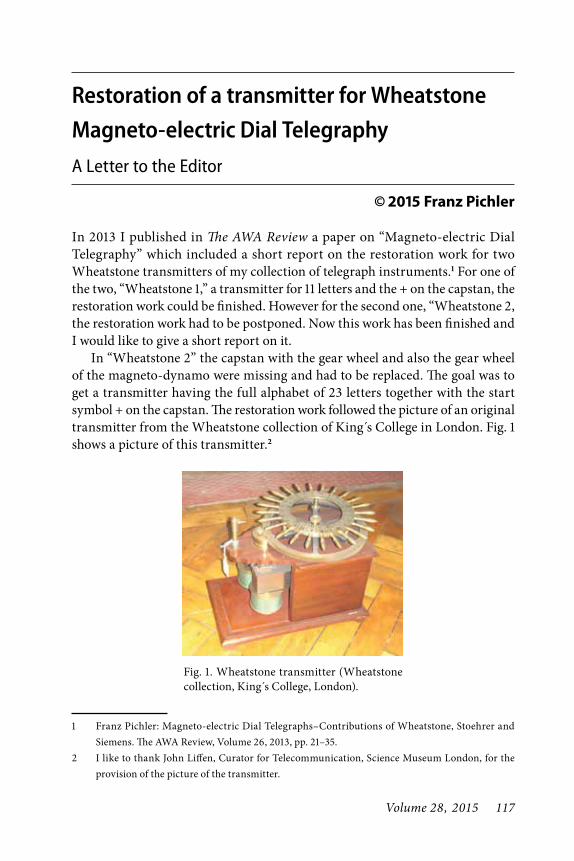
Volume 28, 2015 117
Restoration of a transmitter for Wheatstone Magneto-electric Dial TelegraphyA Letter to the Editor
© 2015 Franz Pichler
In 2013 I published in The AWA Review a paper on “Magneto-electric Dial Telegraphy” which included a short report on the restoration work for two Wheatstone transmitters of my collection of telegraph instruments.1 For one of the two, “Wheatstone 1,” a transmitter for 11 letters and the + on the capstan, the restoration work could be finished. However for the second one, “Wheatstone 2, the restoration work had to be postponed. Now this work has been finished and I would like to give a short report on it.
In “Wheatstone 2” the capstan with the gear wheel and also the gear wheel of the magneto-dynamo were missing and had to be replaced. The goal was to get a transmitter having the full alphabet of 23 letters together with the start symbol + on the capstan. The restoration work followed the picture of an original transmitter from the Wheatstone collection of King s College in London. Fig. 1 shows a picture of this transmitter.2
1 Franz Pichler: Magneto-electric Dial Telegraphs–Contributions of Wheatstone, Stoehrer and Siemens. The AWA Review, Volume 26, 2013, pp. 21–35.
2 I like to thank John Liffen, Curator for Telecommunication, Science Museum London, for the provision of the picture of the transmitter.
Fig. 1. Wheatstone transmitter (Wheatstone collection, King s College, London).
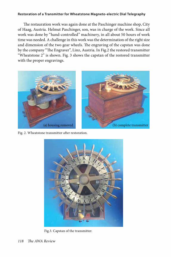
118 The AWA Review
Restoration of a Transmitter for Wheatstone Magneto-electric Dial Telegraphy
The restauration work was again done at the Paschinger machine shop, City of Haag, Austria. Helmut Paschinger, son, was in charge of the work. Since all work was done by “hand-controlled” machinery, in all about 50 hours of work time was needed. A challenge in this work was the determination of the right size and dimension of the two gear wheels. The engraving of the capstan was done by the company “The Engraver”, Linz, Austria. In Fig.2 the restored transmitter “Wheatstone 2” is shown. Fig. 3 shows the capstan of the restored transmitter with the proper engravings.
(b) complete transmitter(a) housing removed
Fig. 2. Wheatstone transmitter after restoration.
Fig.3. Capstan of the transmitter.

Volume 28, 2015 119
Franz Pichler
With the restored Wheatstone transmitter an interesting piece from the first days of electrical telegraphy is now available for museum purposes. For the reader it might be interesting to recall some details on the invention and the efforts for its promotion. The invention of this transmitter, then called “communicator” goes back to the English patent No. 8345 of January 21, 1840, issued to Charles Wheatstone and William Fothergill Cooke. The system which uses this trans-mitter is denoted there as the “electromagnetic telegraph”. From 1843 on, Cooke and Wheatstone started a promotion to propose the “electromagnetic telegraph” for the public. To interest investors an experimental line on the “Great Western Railway” between London and Slough stations was erected, and for a admission fee of 1 shilling one could watch the operation of sending messages. Fig. 4 shows a picture of the “electro-magnetic telegraph” with the “communicator” (Wheatstone transmitter) on one end and the “indicator” ( Wheatstone receiver) on the other.
Fig.4. The “electro-magnetic telegraph” on the “Great Western Railway”.

120 The AWA Review
Restoration of a Transmitter for Wheatstone Magneto-electric Dial Telegraphy
As this letter tried to show, there now exists one restored copy of the transmit-ter for the “electromagnetic telegraph” of Wheatstone-Cooke in my collection in Puchenau, Austria. A suitable receiver (“indicator”) has been located in the collection of an AWA member in the State of New York. We show this receiver by permission of the owner in Fig. 5.
It would be great if the Atlantic Cable still existed to allow the connection of both pieces and to accomplish a connection from Austria to New York. SMS certainly can do this in an easier way.
Franz Pichler, Puchenau, Austria
Fig 5. Wheatstone receiver for Dial Telegraphy.

Volume 28, 2015 121
A Letter to the Editor
■ On Mon, Jul 21, 2014, John Dolittle wrote:
I greatly enjoyed reading Bart Lee’s article about Clarence Tuska in the latest AWA Review. Quite a life he led. I am of the belief that the statement on page 263 about “the local A.C. Gilbert Company of Hartford,” may be an error. Gilbert ,as an adult ,was a man of Yale Univeristy, and New Haven, not Hartford. My Dad, a few years younger, knew him, and to some extent they were rivals/competitors, for both got involved with early radio in New Haven. In the ’40s and ’50s we lived near his home, which is now for sale.
The Mysto Magic Company at some point was owned by Todd Petrie, and/ or his father, and Gilbert ultimately came to own it or its product rights. Dad knew and was a friend of Todd Petrie, who owned or used a building on Valley Street in the Westville section of New Haven, and many of the radio and electronic parts he assembled or manufactured were produced there, perhaps alongside Mysto items. At some point I believe A.C. Gilbert may have had a connection to use of that building as well.
Gilbert, as I recall, produced some 20 or so multitube radios, and some novelty radio related items. His early radio station was primarily used as an adjunct to his manufacturing operations and for internal company things, although a railroad car was once equipped with a transmitter and traveled around to publicize his company and technological prowess. It didn’t last, whereas Dad’s radio broad-casting ventures continued and thrived, ultimately moving from New Haven to Hartford around 1929 or 30. (See www.WDRCOBG.com and the spring 2013 AWA Journal article, “Franklin Doolittle, Connecticut’s Radio Pioneer.”)
Gilbert’s manufacturing facilities in New Haven mushroomed, while Dad got out of making things to sell in a store. I acknowledge that it is possible Gilbert had some early Hartford Manufacturing or other facility, but if so, am curious where you got that information. Thanks for all the articles you have written over the years, they were enjoyed.
Sincerely, John B. Doolittle, Vienna,VA


Volume 28, 2015 123
Radio in 1922: What the Boys and Girls Knew©2015 Mike Adams
Abstract“Radio in 1922, What the Boys and Girls Knew,” looks at a single year and compares the rise in broadcasting, and what Americans were being told about its significance, with the information young readers were getting in their Radio Boys and Radio Girls series books. This analysis compares what was commonly known by the general reader through how-to and news publications with four 1922 novels about radio. This is the first article from a book project that examines meaning in wireless and radio-themed juvenile fiction. Both story and character are summarized. Ques-tions are asked: First, is the technology presented accurate, and is it hobby or career focused? Beyond the radio aspect, how are the values of authority, patriotism, family, citizenship, race, law and order, religion and charity presented? What is the socio-economic position of the characters? Which values have been transmitted across generations to the current day? And did these stories affect or merely reflect society? This analysis adds perspective to hobbyists who surely operate in a larger circle of influence beyond wireless and radio.
This article presents and analyzes what a young person may have been reading about radio in 1922 America. That year was an important one in the transition from the dots and dashes of the wire-less hobby to the radio as a source of entertainment and information. Exam-ined here are four novels of so-called juvenile series fiction, all with the title of Radio Boys or Radio Girls. Each tries to offer for the young reader the use of radio within its story. All published in 1922, some are non-stop drama, while others are slow moving hobby story as the various characters build and demonstrate their first crystal set. Of
the four, some are educational while others use radio purely in the service of adventure. And although works of fiction, all have at their center some reasonably accurate radio technology information. These four volumes show some of what the boys and girls knew.
By 1922 Radio was rapidly entering the American home. Imagine yourself in a dimly-lit room with a bright blue line bisecting the room where you are standing. This line represents 1922. On one side of the line is radio past: the wireless era, the just concluded World War, the proliferation of amateur radio and radio construction as a hobby. On

124 The AWA Review
Radio in 1922: What the Boys and Girls Knew
the floor are Marconi spark gap trans-mitters, batteries, a Fessenden alter-nator radiotelephone, de Forest’s first tube, and a stack of Modern Electrics magazines. On the other side of this line is radio’s future: Radios with tubes and speakers, radios in wood cabinets with single knob tuning, radio regula-tion, radio networks, advertising, and programming featuring concerts, news, lectures and sporting events. The blue line of 1922 represents the apex of the transition from young men building crystals sets and listening using head-phones to the store-bought radio with the horn loudspeaker that is now begin-ning to interest mom and dad.
A number of books were published in 1922, all of them written to take advantage of the so-called radio boom, a time of great possibility in broadcast-ing for an audience. If you wanted a radio in 1920 you had to ask your young son or daughter to build it for you. You also had to ask them to show you how to operate it, how to separate the music from the Morse Code, how to tune in anything in those early days. It was by 1922 that radio started to come of age, and in addition to the radio-themed periodicals such as Radio News, there appeared books with titles like Radio Enters the Home, The ABCs of Radio, and The Home Radio, How to Make and Use it. These books, which were both construction information and a guide to the purchase of the ready-made radio made 1922 an important year for broadcasting.
Radio Enters the Home was a 1922 book by the Radio Corporation of
America that both gave instructions for building, installing, and operating radios, and sold the individual parts and a collection of ready-made radios in all price ranges. RCA promised it would explain “How to enjoy popular Radio Broadcasting.” This included “Complete instructions and descrip-tion of apparatus.” And it flipped its emphasis, putting the amateur in a sec-ondary role: “For those who desire to be entertained with concerts, lectures, dance music—as well as for the radio amateur.”1 This book also promised in its advertisement for its basic crystal set that “Any one who can operate a talk-ing machine or a camera can operate the Aeriola Jr.”2 Selling for thirty-five cents, this well-illustrated book of 125 pages was the bridge from the hobbyist/set builder to the adult seeking a ready-made radio for the programming now being aired. It was written to excite as it described radio: “With magic touch it has relieved isolation and neglect on land and sea.”3 It begins to lay out the benefits of radio as it was understood in 1922, a combination of developing entertainment and the more-estab-lished two-way communication uses. It made many references to safety at sea and the connection between the ship and the land: “It has given the voice of hope and salvation to ships and pas-sengers whose despair and tragic fate formerly were shrouded in silence.”4
RCA promised that radio will add to a “fuller and richer home life, as it carries into the homes of rich and poor alike a modern facility of plea-sure and education which is binding

Volume 28, 2015 125
Adams
people together in a new and demo-cratic brother hood.”5 Added to this phi-losophy of radio were many technical and operational details organized by topic: what is the broadcasting station,
what is the antenna, what is detecting and tuning, and what is “listening in?” And what about advertising? The Radio Corporation and its affiliates in manu-facturing believed that it would be the
Fig. 1. Cover, Radio Enters the Home.

126 The AWA Review
Radio in 1922: What the Boys and Girls Knew
Fig. 2. Cover, the ABCs of Radio.

Volume 28, 2015 127
Adams
sale of radios that would fund the con-tent of the new media. So while it was the purpose of RCA to educate and sell parts and sets to the newly-interested consumer, another book, the ABCs of Radio by Waldemar Kaempffert, also 1922, is all about the excitement of radio even though it had nothing to sell but knowledge. The radio colum-nist of the New York Times offered this opinion about Mr. Kaempffert’s book: “The simplicity of its radio language is a revelation, omitting as it does the dull technical descriptions which are mean-ingless to the average radio novice.”6 What that reporter seems to imply is that while there are many books telling how to construct and operate the radio, this author writes for the technical neo-phyte, typified by this passage: “The first question that a thinking man is sure to ask about radio is this: How does the music reach me? The windows are closed, and yet I hear.”7 An interesting addition to this 1922 book is the listing of the stations on the air by geographi-cal location. All fifty of these share a single channel, 360 meters.
Another volume from 1922, The Home Radio: How to Make and Use it, by A. Hyatt Verrill, directly relates to this discussion because it was writ-ten by the author of the juvenile series titled the Radio Detectives. Mr. Verrill explains: “This book is not intended as a treatise on radio telephony nor has any attempt been made to enter deeply into an explanation or discussion of the scientific phase of radio transmission.”8 He clearly identifies his audience: “It is intended and designed particularly for
the use of amateurs, boys, and those who wish to know how to make, use or adjust wireless telephone instruments and who are not interested in, or do not care to learn, the technicalities of practical electricity as applied to wire-less work.”9 This book also introduces the possibilities of career. It is written in a way that could be useful to both the young set builder and his or her parents. Overall, these 1922 books offer a transition between pure hobby and radio as useful home media for the entire family.
Fig. 3. The list of stations on the air in 1922 from the ABCs of Radio.

128 The AWA Review
Radio in 1922: What the Boys and Girls Knew
A hint of radio’s future was also available in those periodicals of the day read mostly by adults. From the January 1922 Radio News editorial: “In 1922, we may safely predict that mil-lions of homes will have their radio receiving stations right in their parlors.” By March 1922 it was clear that these were “Boom Times in Radio. People are storming the stores and are lining up behind the showcases six deep, and very often breaking the showcases in the bargain.” In that same issue there was a prediction that in the 21st century “the broadcasting of news by radiophone had long displaced the daily newspaper.” An editorial in July 1922 spoke to the
operation of the radio itself: “Indeed, radio engineers, as well as the entire technical fraternity today, bend every effort towards simplifying every radio set to such an extent that it will come into the class of the phonograph or the automobile; that is, that the owner does not need to know anything of the radio whatsoever in order to operate his set.”10 Reinforcing this the March, 1922 Popular Science presented a list of the stations now broadcasting under the headline “First American radio charts show nation is now blanketed by wire-less news and music.”11
So by 1922 radio was said to be rap-idly moving from the garage into the house, from the basement to the living room, and from a young person’s hobby into a potentially, commercially-viable media format. From tinkerer to audi-ence, from code to dance music, this was radio in 1922. The written evidence indicates a media that is forming before the eyes and ears of a nation, with the news about it communicated in books, newspapers and periodicals. Concur-rently with these “how-to” and “radio in the news” publications, there were at least three Radio Boys and one Radio Girls fiction series, profiled here, that communicated to the young reader some of what their parents were read-ing about in the newspapers. In addition to technical knowledge, they were likely beginning to understand the post-war spirit of inventiveness and so-called American knowhow. The young reader was part of the growing audience for juvenile-themed stories not only about radio but automobiles, airplanes and
Fig. 4. Cover, The Home Radio: How to Make and Use it.

Volume 28, 2015 129
Adams
Fig. 5. Cover, a 1922 Radio News.

130 The AWA Review
Radio in 1922: What the Boys and Girls Knew
submarines. But beyond radio and adventure, these books also commu-nicated culture, attitudes and values. A question asked and answered in this article is simply, “What did the boys and girls know and when did they know it?
There are many ways to read a work of juvenile fiction. One is for pure escape and enjoyment, and another is to look at how the story can be viewed in the context of a developing world of nearly a century ago. What is the social and economic setting of the story? What are the values presented? What are considered the important issues of the time? Are the characters well-developed, do they self-examine their lives, do they think critically? How do they interact with authority? How is technology presented and applied? Are the descriptions of wireless and radio devices accurate? Is that techni-cal content hobby or career focused? The methodology used will be that of summarizing each book and reacting to story and character. Each story is looked at from all points of reference: science, humanities, history, art and lit-erature. Analyzed is obsolete language, racial stereotypes, technical credibility, and the quality of writing as well as the external and internal development of the main characters. Character and story will be examined in a social, eco-nomic, technical, and cultural context.
The authors of these radio and wireless-themed juvenile fiction books are a varied lot; Many of them were freelance writers and journalists who wrote juveniles for extra income. The largest producer of these books was the
Literary Syndicate of Edward Strate-meyer, which released over a thousand volumes all under pseudonyms. His Syndicate was responsible for Tom Swift, The Radio Boys and Girls, and later Nancy Drew and the Hardy Boys. Other authors were “real,” with various occupations in addition to writing the juveniles. There was a Harvard Physics Professor who wrote boys books on electricity and wireless, and the editor of a New York newspaper who wrote one of the major Radio Boys series. There was a college dean, a chemistry professor, and several ministers. Many were journalists and most were college graduates. The quality of storytelling and writing in these books ranges from inspired to dreadful.
Young people in these stories seem to understand quite a bit: In the Radio Detectives, 1922, a boy explains: “I can get Pittsburgh and I can get spark messages from Cuba and Canada, and last night I picked up a message from Balboa. I’ll hear England and France before I am satisfied!”12 Of course it was more than what would be known as broadcasting: “From out of the silent air came various sounds to the boys’ impatient ears, little buzzing dots and dashes from local stations; the faint sounds of a phonograph record from some amateur’s radio phone; frag-ments of speech from a broadcasting station.”13 There was much confusion in 1922 over the few laws that gov-erned the emerging media, and there was even a very serious juvenile story about the feared Radio Inspector. In Curley Carson Listens In, 1922, the

Volume 28, 2015 131
Adams
Fig. 6. Cover, Radio Detectives.

132 The AWA Review
Radio in 1922: What the Boys and Girls Knew
radio police are introduced: “When will people become used to this new thing, the radio-phone? When will they learn that it is a great, new servant of mankind and not a toy? When will they take time to instruct themselves regarding the rights of others? When will they develop a conscience which will compel them to consider the rights of others? It is my duty not alone to detect but to teach.”14 When Curlie was told that a powerful illegal transmission had been discovered on 600 meters he replied: “Six hundred! Why that’s what they use for S.O.S. at sea! It’s criminal! Endangers every ship in distress. Five years in prison for it.”15
Presented in this article are four examples of books published in the year 1922 under the series title of Radio Boys and Radio Girls. Each of the four are the first volumes in their respective series; two are from the Stratemeyer Syndicate and two are by independent authors, all of whom will be identified at the beginning of each book analysis. Two of these stories concentrate on broad-casting, then called “listening in,” while the other two feature radio primarily for communication. The ultimate goal of this project is a book telling a com-plete story of 80 plus communications-themed juvenile fiction works, their authors, and the significance of each volume. The range of books examined for the larger project begins with early electricity, pre-1900, wireless, broad-casting, then to 1930 and beyond. This article is a small sample of a work in progress. The first book comes from the most popular boys radio series, that
of Allen Chapman. Volume one is The Radio Boys First Wireless, or Winning the Ferberton Prize.
The Radio Boys First WirelessThe Radio Boys credited author, Allen Chapman, was a pseudonym used by the Stratemeyer Syndicate. The actual author of the first twelve volumes, John William Duffield, 1859–1946, wrote other juveniles under his real name but also as Franklin Dixon for the Ted Scott Flying Adventures and Roy Rockwood for Bomba the Jungle Boy. Duffield was an educated man, an 1882 graduate of New York’s Colgate College and Colgate Seminary in 1884. The latter degree likely provided an inspiration for one of the recurring adult characters in the Radio Boys series, minister and radio expert Dr. Dale. The author’s ministe-rial background may also explain the emphasis on charity in these stories. These boys aid the blind and crippled in a number of volumes.
Here is how the series was promoted and positioned: “A new series for boys giving full details of radio work, both in sending and receiving, showing how small amateur sets can be made and operated, and how some boys got a lot of fun and adventure out of what they did.”16 So this may be a hobby series, but there are adventures connected with each radio moment. Wireless hero Jack Binns introduced each volume, and for this initial volume he lauds the contribution of the boy experimenters, naming Armstrong and Edison, and telling how both began in their home laboratories. He also understands that

Volume 28, 2015 133
Adams
in this year, 1922, there is an explosion in radio interest: “It is very appropriate at this moment when radio has taken the country by storm, and aroused an enthusiasm never before equaled, that the possibilities for boys in this art should be brought out in the inter-esting and readable manner shown in the first book of this series.”17 But this first radio volume, The Radio Boys First Wireless or Winning the Ferber-ton Prize, starts with a small problem. While the interior of the dust jacket indicates there is a Pemberton Prize, the title of the book itself it reads the Ferberton Prize. This probably indi-cates the time pressure to quickly get these books to market.
The boys are introduced as they leave high school. The four are Bob, Joe, Jimmy, and Herb. Jimmy is only in the cast to be made fun of for his excess weight, and Herb does very little. The only necessary Radio Boys are Bob and Joe. They are making plans to attend a radio event later that evening, described as a lecture about radio construction. Also in the cast are three bullies, Buck, Carl, and Terry, who taunt the boys and make fun of the radio: “The whole thing is bunk. Telephoning without wires! You might as well talk of walking without legs.18 This sets up a 13 volume haranguing of the Radio Boys by these three bad boys who are described as “furtive” and “unwholesome.” The boys drop a few names like Marconi, but the bullies have never heard of them. These exchanges will happen often, fists are raised, there is pushing and shoving, but mostly it was words that
were employed. These bullies return in every volume.
In this series there is always an adventure on the very first page, and here an out of control auto threat-ens the group. The boys, led by Bob, immediately respond by rushing to save the driver, a twenty year old girl named Nellie, from the now burning car. While the doctor is summoned, the traditional Syndicate method of stopping a story during a dramatic moment is employed as the Radio Boys are explained in more detail. The boys live in the small town of Clintonia, 75 miles from New York City. Bob and Joe are 15, so they can be placed in about the 9th or 10th grade, early high school. Their fathers are professional men in town. Bob is considered the leader. This is really all that the reader learns about these two, as the Syndicate formula nor-mally emphasizes story over character. Overall, it is easy to discern the good from the bad, and these radio lads are positive role models for their readers. Bob and Joe are described as athletic and they had already saved a young girl from a burning car. The doctor tells the boys: “You boys deserve great credit for the quickness and decision with which you acted. The fire might have reached her in a few seconds more.”19
These boys are very much inclined to work with the adult leaders of the town. Now they plan to work with another recurring character, their pas-tor Dr. Dale, who is the town’s radio expert. Dale invites them to come to his house to listen to the radio, described as a box-like contrivance: “It had a number

134 The AWA Review
Radio in 1922: What the Boys and Girls Knew
Fig. 7. Cover, The Radio Boys First Wireless

Volume 28, 2015 135
Adams
of polished knobs and dials and several groups of wires that seemed to lead in or out of the instrument. Connected with it was a horn as was common enough in the early days of the pho-nograph.”20 The pastor approaches the radio with some reverence and begins to explain what he is about to do: “I’m going to give you a little idea of what the wireless telephone can do.”21 The excitement in the room was palpable: “The boys watched him breathlessly as he handled two of the knobs at the side of the box.”22 Dale suggests that the best way to learn is for the boys to build their own set, and to assist them he has set up a shop in his garage where he will hold weekly classes. The other story line is explained the next day as Bob and Joe visit Nellie who is now recovering from the auto accident, and in conversation tells them that she might be cheated out of some inheritance: “There’s dis-honesty involved. I know there is but I don’t see how I’m going to prove it.”23 The possible swindler’s name is Dan Cassey. This is the book’s first mystery for the boys to solve.
Saturday arrives and Dr. Dale holds his first radio construction class. He tells the boys the first thing they need is 125 feet of wire for an antenna, and that should be connected to a high place, like a barn roof. Next he describes the detector as he picked up a piece of crystal and a bronze wire: “When this wire comes in contact with this bit of crystal the mysterious waves become audible vibrations.”24 Again, he seems to oversimplify although he is correct about the crystal and wire, the latter
called a cat’s whisker. But the waves are not mysterious, and what the crystal does is rectify, that is convert the radio frequency waves into audio frequency waves or vibrations. But his way of explaining is correct if overly basic. He then describes the final piece, a hand wound coil of wire with sliders used to tune in the station. One thing he does add to the construction of the coil is important: “You will notice that the wire is covered with cotton except for this little strip of wire extending length-wise where I’ve scraped the cotton off with sandpaper so as to accommodate the sliding contacts.”25
In the next chapter the earphones are connected. Dale then explains something that may be accurate in a non-technical way: “But as the elec-trical vibrations, if left alone, would have a good deal of trouble in passing through the telephone receiver, we must have a condenser to help them out.”26 Here is a more technical explanation for this provided by Berkeley Profes-sor John Staples: “The incoming RF is rectified by the crystal but still exists as RF with a modulation envelope on it. A condenser across the headphones
Fig. 8. Crystal and cat whisker, author photograph.
136 The AWA Review
Radio in 1922: What the Boys and Girls Knew
integrates out the RF component (fast) but leaves the audio modulation com-ponent (slow). The coils in the head-phones would show a high impedance to the RF component, and without the condenser, the total current through the headphones would be much smaller if it were not for the condenser across the headphones.”27 Dale explains how to make a condenser using a piece of mica as a dielectric, then gluing a piece of foil to each side, finally placing it in series with the set and earphone. This series is the one radio hobbyists have been waiting for. The adult tutor here, Pastor Dale, now explains that most of what was used to receive radio can be found around the house, the two exceptions being the piece of crystal and the telephone headset. He has just described and helped the boys build a five dollar radio. Finally there is an explanation of how to properly install the long wire antenna. So far there is a lot of radio construction content in this first Radio Boys book.
Radio Boy Jimmy is said to always be eating and the others make fun of him many times in every chapter of every story. They call him fat boy. They say he is the fattest boy in school. This is real bullying, even if it is soft-pedaled as just “good clean fun.” For whom? It feels very hurtful. Back to set building, the tuning coil is finished and there is another discussion about the purpose of the condenser: “It seems to be a sort of equalizer for the electric current, storing it up when it is strong and giv-ing it out when it’s weak. It prevents the current getting too strong at times
and burning something out.”28 Now the plan is for the Radio Boys to “listen in” the following night and are they excited! The finished radio is installed in Bob’s bedroom and the boys add a lightning disconnect switch. They don their headsets as Bob tunes in. After some experimental slides of the tuning coil and the cat’s whisker touching just the right spot on the crystal they hear music, and it’s a wonderful thing for these young boys to have this success, to have built their own radio: “I think we can call our set a success fellows. Why, we can sit here and hear that orchestra just as well as though we were in the same hall with it.”29
Dr. Dale brings another recur-ring character, local radio inspector Mr. Brandon, to the boy’s house and he pronounces their radio as the best example of a mature work he has seen. They ask him to help them get licenses so they can send as well as receive. Here is another important adult role model who has earned the respect of our boys. He tells them of his experience in the aviation service: “It was the war that speeded up the growth of radio.”30 Dale hears news bulletins on the boy’s radio and proclaims: “I’d advise you to listen for a bit. It’s way ahead of reading a newspaper, I assure you.”31 It would take nearly one hundred years for the newspaper’s slow demise, and it would be because of the Internet, not radio. Inspector Brandon is queried about his role in radio: “If anyone takes a chance and tries to send without a license, it’s up to me to locate him and tell him what’s what.”32 For these radio boys it
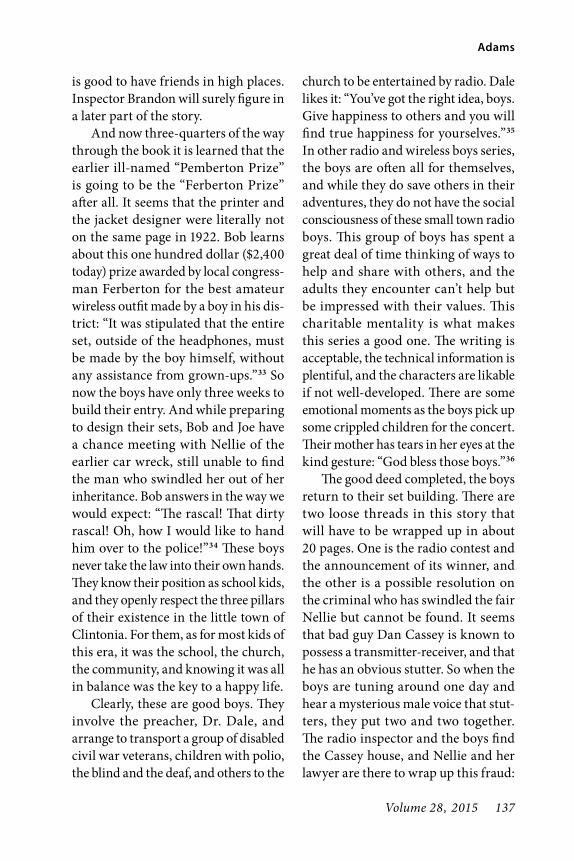
Volume 28, 2015 137
Adams
is good to have friends in high places. Inspector Brandon will surely figure in a later part of the story.
And now three-quarters of the way through the book it is learned that the earlier ill-named “Pemberton Prize” is going to be the “Ferberton Prize” after all. It seems that the printer and the jacket designer were literally not on the same page in 1922. Bob learns about this one hundred dollar ($2,400 today) prize awarded by local congress-man Ferberton for the best amateur wireless outfit made by a boy in his dis-trict: “It was stipulated that the entire set, outside of the headphones, must be made by the boy himself, without any assistance from grown-ups.”33 So now the boys have only three weeks to build their entry. And while preparing to design their sets, Bob and Joe have a chance meeting with Nellie of the earlier car wreck, still unable to find the man who swindled her out of her inheritance. Bob answers in the way we would expect: “The rascal! That dirty rascal! Oh, how I would like to hand him over to the police!”34 These boys never take the law into their own hands. They know their position as school kids, and they openly respect the three pillars of their existence in the little town of Clintonia. For them, as for most kids of this era, it was the school, the church, the community, and knowing it was all in balance was the key to a happy life.
Clearly, these are good boys. They involve the preacher, Dr. Dale, and arrange to transport a group of disabled civil war veterans, children with polio, the blind and the deaf, and others to the
church to be entertained by radio. Dale likes it: “You’ve got the right idea, boys. Give happiness to others and you will find true happiness for yourselves.”35 In other radio and wireless boys series, the boys are often all for themselves, and while they do save others in their adventures, they do not have the social consciousness of these small town radio boys. This group of boys has spent a great deal of time thinking of ways to help and share with others, and the adults they encounter can’t help but be impressed with their values. This charitable mentality is what makes this series a good one. The writing is acceptable, the technical information is plentiful, and the characters are likable if not well-developed. There are some emotional moments as the boys pick up some crippled children for the concert. Their mother has tears in her eyes at the kind gesture: “God bless those boys.”36
The good deed completed, the boys return to their set building. There are two loose threads in this story that will have to be wrapped up in about 20 pages. One is the radio contest and the announcement of its winner, and the other is a possible resolution on the criminal who has swindled the fair Nellie but cannot be found. It seems that bad guy Dan Cassey is known to possess a transmitter-receiver, and that he has an obvious stutter. So when the boys are tuning around one day and hear a mysterious male voice that stut-ters, they put two and two together. The radio inspector and the boys find the Cassey house, and Nellie and her lawyer are there to wrap up this fraud:

138 The AWA Review
Radio in 1922: What the Boys and Girls Knew
“The game’s up Cassey, we’ve got you at last. The money or the mortgage.”37 He hands over the mortgage and falls to his knees begging for leniency. Then the contest results are announced by Con-gressman Ferberton, and as you might have guessed, Bob won first prize, the one hundred dollars. Joe was second. After it is all over, Bob concludes, “Radio, the most wonderful thing in the world.”38 In this first of thirteen volumes the story of receiver construc-tion and reward is told, a minor mystery is solved, and the boys are introduced as good, clean living, upstanding citi-zens. They are like a combination of the Boy Scouts, “thrifty, brave, clean and reverent,” and Sunday School kids. So far the series has presented some useful technical information, but after all it is just about the construction of a first radio, the crystal set. In future volumes these boys will use tubes and horn speakers, get their ham licenses and aid first responders and save lives. Pastor Dale will install a transmitter in his church, an early foray into religious broadcasting. These boys will remain 15 years old for the thirteen volumes while radio grows up.
Radio Boys LoyaltyRadio Boys Loyalty, or Bill Brown Lis-tens In, by Wayne Whipple and S. F. Aaron, 1922, was one of a number of series titled “Radio Boys,” all written by different authors. This one, written by Wayne Whipple, 1856–1942, and Sam-uel Francis Aaron, 1862–1947, is intro-duced by none other than the Wizard of Menlo Park himself, Thomas Edison (or
more likely a ghost writer). Edison adds over his famous signature, “I have great admiration and high regard for Mar-coni the pioneer inventor of wireless telegraphic communication.”39 He says this because according to the Preface, “We have introduced a typical young Italian student at the school of technol-ogy, who brings ‘Bill’ and ‘Gus’ into closer touch with life and the stirring example of his young countryman Mar-coni.”40 But alas, today not much detail is known about the authors. Whipple is credited for several historical books, including titles on Lincoln, Washing-ton, the Liberty Bell, and the White House. Aaron is only credited with the two Radio Boys volumes, and only as a co-author with Whipple.
In the opening scene the two boys, Bill and Gus, are discussing their accep-tance at the local tech college, and how they will get involved with the broad-casting station there. They also raise a darker issue, that of the possibility that they will be hazed as new students. Bill plans to come prepared: “I guess it’s me for carrying a gun.”41 Gus does not agree: “There are better things too, than a gun; not so crude and not illegal.”42 This 1922 guns-on-campus reference has reappeared in the news today as gun proponents want people to be able to carry guns on college campuses, always a bad idea. The boys agree that they will not stand for being hazed, but they will not shoot their way out of the situa-tion. They will either turn the other cheek or run away. Hazing is also an issue very much alive on the campus of today. Bill and Gus are now students

Volume 28, 2015 139
Adams
at a “university of broad constructive teaching, with departments of engi-neering, chemistry, manual training and biology.”43 This is the STEM (an acronym of the technical curriculum in higher education: Science, Technology, Engineering, Math) life in 1922. This entire book will take place at college.
The character development of the two boys is enough that the reader begins to know them. It is said that the boys live just outside of New York City in Freeport on Long Island. They are top students and radio set builders. Bill is said to be the class genius, a fine young man, and according to one of his teachers, “possessed the mind of a philosopher and the expressiveness of a poet.”44 And, in a first in this study of juvenile fiction, Bill is a hero with a handicap, a special needs radio boy who uses a crutch because of a twisted leg since birth. Gus is also described as a top student and was said to have muscles while Bill had the brains. Both boys had just graduated from high school so it can be assumed that they are 18 or 19 years old. One thing that is not clear is the parental situation, as neither mother or father are ever mentioned in the story. There is some hint as to their socio-economic status when they encounter fellow students who they call “well-dressed” kids of privilege, prompting the boys to discuss their situation, saying that they saved for years to attend this college, and that they had to be careful with their money.
On their first day at Tech, an upper class student taunts a new freshman: “Hazing, long since taboo or forbidden
in many educational institutions, was still a part of Marshallton Tech by rea-son of the belief that a high mentality and virile spirit demanded the extreme mental and physical showdown which hazing is supposed to bring out.”45 It mainly consists of taking the clothes off of the new students. Bill and Gus call it what it is, mean. When threatened with hazing Bill pulls out a pistol to which the hazers say, “you’re exempt of course. We don’t bother with cripples, kids, old ladies.”46 So the boys have come to col-lege armed. But lest you think that there are violent tendencies in these boys, the pistol was revealed to be a fake, really a cigar lighter. The boys are not hazed.
They carry this anti-hazing a bit too far as they invite the hazers to come to their room the next day. When the bullies show up at the door they are greeted with a maze of copper wire, and you guessed it, when the hazers try to remove the wire, the juice is applied and: “Pandemonium! Cries of distress! Yells of something more than discomfort, howls of dismay.”47 Later in this story of the college experience in a school for geeks, Bill and Gus are building sets for fellow students, get-ting 60 dollars for a high quality radio costing them 15 dollars in parts, and 20 dollars for a crystal set that cost 4 dol-lars in parts. The boys had also opened a radio lab and charged 25 cents an hour to a student who wanted access to tools and help with radio building. In their lab they meet the Italian boy, Tony Sebaste, and he wants to build a radio. It is discovered that Tony has been a recluse at the school because of

140 The AWA Review
Radio in 1922: What the Boys and Girls Knew
his nationality, but now his involve-ment in radio construction seems to be bringing in him out of his shell. He is the only “other” in a class of white American boys and he is called names, “wop and spaghetti.”48 This is a sensi-tive story in its treatment of minorities, the disabled, and the bullying that often accompanies the school experience. This story could be characterized as “College Life Procedural.”
As it turns out, Tony’s family knows Signor Marconi, so he is in the right place at the right time according to Bill: “This school has gone wireless mad, and the country is pretty much in the same fix, and for the reason that radio is about the biggest thing in the world.”49 The Marconi yacht is close by in the harbor, and the boys and Tony plan an event in which they will communicate with the great one. The event, a school assembly, begins with Bill defining radio: “A good many folks are wondering how it happens - how speech can be turned into electricity that goes shooting in all directions and how this is turned back into speech again.”50 He also compares radio to the wired telephone, substituting wires for the ether: “The voice in the receiver is turned into electrical energy that passes over wires and at the other end turns again into sounds exactly like the voice that started it.”51 True but simple, and the explanations do not add to the tech-nical education implied in the story, nor do they add to a reader’s understanding of electricity and radio. Surely in this school the students are learning about volts and amps and ohms. The lecture
continues as Bill explains: “Now, there’s no use going into the technicalities of construction, that’s a thing that must be studied out and thought over, not mussed up in a talk like this.”52
Later in the talk Bill gives a more satisfying explanation of a radio as he points to the parts in the image: “Here’s your aerial and its ground, between which is placed your variable condenser and tuning coil, thus, off here between condenser and coil comes the wire to your vacuum tube, with its fixed con-denser and grid leads, the wire being connected directly to the grid, while here the wire from the tube plate is connected with the six volt storage battery and in turn with the phones to the ground wire, the wire is carried thus through a secondary dry cell bat-tery, on each side of which the wires are
Fig. 9. Bill Brown in the classroom at the blackboard from Radio Boys Loyalty.

Volume 28, 2015 141
Adams
taken off to a rheostat.”53 Next, Tony gives a mini-biography of his friend and neighbor Marconi, how he was home-schooled in electricity, and while his family had the means to provide him with the best education and the best tools he tells the American boys: “In this country a poor boy, without social hindrances, has an equal chance with a rich lad.”54 Tony also explained that a man of Marconi’s station could have led the life of leisure, “but if he had not also possessed an earnest, painstaking and brilliant mind he could have gained no distinction.”55 The point Tony is try-ing to make is that wealth alone does not make a great inventor. He uses the speech to trace the invention process Marconi followed to send and receive a spark, but he does not give the reader the background, like the initial work of Hertz and Lodge. He summarizes with the transatlantic transmission of the Morse letter “S” or dit dit dit in December, 1901.
Now it is Marconi’s turn to broad-cast an agreed upon message to his friend Tony and the school assembly audience. He is modest: “I confess my being called upon seems rather unusual, but yet I am glad to communicate with an American educational institution, especially one devoted to physical knowledge, mechanics and electric-ity.”56 He continues with his best advice: “Study, close application, the not too stringent adherence to formulae and old methods are bound to win. Inspiration, vision, the seizing of opportunities to improve, the wish to gain something desired, these are keynotes to success
in the field of mechanical endeavor and scientific discovery. It’s up to you.”57 The author has rightly used Marconi in a plausible way in order to excite his young readers about a career in engi-neering. As opposed to an immediate launching into an adventure story, these radio boys will take their time, establish their credentials as scientists-heroes of a more cerebral type. There will be time for drama later.
There was still a desire by a few to “get even” with Bill for his electri-cal shock trick on the hazing leaders. There was also a jealousy among a small group of small-minded upperclassmen because of the attention shown Bill for his radio skills. There were attempts to goad Bill into a fight but he tries to deflect the threats with humor: “You wouldn’t really hit a fellow who is lame, would you?”58 But there are several who still want to “get” Bill and Gus, and one named Malatesta begins by damaging the radio lab, breaking sets and tools using a hammer found at the scene. Another student saw it happen and so they know who is responsible and in a brief values discussion it is decided to report the crime to the school presi-dent. First there is a clarification about what loyalty means, loyalty being the title of this book. First, Bill: “But we aren’t going to squeal on a fellow stu-dent,” with the answer by Gus, “This is no prank. It’s a crime and it would be another to keep it to myself. Loyalty to the school demands that we squeal.”59 To ensure that the eyewitness evidence is reinforced by science, they note the fingerprints on the offending hammer

142 The AWA Review
Radio in 1922: What the Boys and Girls Knew
and decide to find the malefactor and fingerprint him. They tell the president of their plans. The fingerprints match and Malatesta is booted out of Tech. Again, while crime solving in these stories often gives the appearance of non-law enforcement boys as judge, jury and executioner, it should be noted that before making a decision the col-lege president had both eyewitness and incontrovertible physical evidence. This is a logical story.
There was a bit of drama in the boxing ring as the older hazing leader challenges Gus to a match. Gus refuses initially, but the other goads him into it. Gus knocks the boy out and everyone fears he is dead: “They must know he was not murderously inclined, and that he hated to hurt anyone, anything, an animal, a bug even; also that he would not run away if they wanted to arrest him.”60 This is the first time Gus has factored in a prominent role in this story, and he is self-reflecting, won-dering what the future will bring if he is judged a murderer. He visualizes prison, ostracism, and being kicked out of school. He asks Bill for help and they touch and bond in a very real way and in their darkest hour the theme of loyalty is re-introduced: “Bill stood by Gus, his hand on his chum’s head. Sel-dom was there any real show of tender-ness between these lads, but there was a loyalty that made such a demonstration unnecessary.”61 Thus the theme of loy-alty is used again, and in a subtle way, adding to the character development of these radio boys, who are becoming excellent role models for the juvenile
audience. In the end it is discovered that the student is really alive as he comes to and there is a collective sigh of relief.
Meanwhile the Italian Tony has disappeared, and the story drifts from an unsolved kidnapping to a baseball story that takes up three chapters with just play by play. It is as if the writer was told that to sell books he needs to add lots of sports. Or perhaps Whip-ple told co-writer Aaron: “I am going out of town for a while. Can you write three baseball chapters?” Meanwhile Tony is still in the hands of kidnap-pers, probably tied up in a dank base-ment with only bread and water for sustenance. Now listening to the radio again, they hear what is believed to be a clue concerning Tony. There are the faint words—Italian . . . ransom . . . banker, and a location, all adding up to the Malatesta gang having the boy on board a ship headed for a local harbor. Gus heads for the location with a radio to keep in touch with Bill who is at a nearby fisherman’s cottage. Close by in the woods overlooking the ocean was a small cabin guarded by the Malatesta gang, and Gus was sure that Tony was a prisoner there. They need a rescue plan and it starts with radio, a version of “calling all cars.” They are sending broadcast messages to the boy’s father and the police on a wave length of 360 meters. The Malatesta gang was caught and imprisoned and later deported back to Sicily. In the end Tony’s father, who you recall is a friend of Marconi, radios him from the school and tells him that his son is safe. To which the inven-tor replies: “Senatore Marconi sends

Volume 28, 2015 143
Adams
congratulations to Signor Sabaste that his son had been restored to him and that two criminals, though they are our countrymen, are to be sent from America, where too many such have come and belittled the name of Italy.”62
This story is an example of well-meaning but meandering writing, going from classroom to minor cri-sis to lecture to morality play to final drama. It is almost as if the author was remembering his college years and now attempted to make that memory into a book while adding more excitement than in his own experience. Perhaps he was a young science student once. Mostly though, Radio Boys Loyalty is driven by the perfect character of Bill, the smartest student, the most self-effacing, the kindest and most honest, friend to all who never makes wrong choices. The other boy Gus has proved himself another perfect example of a young man. The writing is generally good, the technical parts are accurate but lacking scientific depth, and the school scenes are credible, if too plen-tiful. And Bill is a good example of a person with a physical disability who overcomes every obstacle in his path. He is able to study, make radios, and participate in any activity not impeded by being on crutches, and he makes up for his disability with his extraordinary mind and his sense of right and wrong. Oddly, while Tony is their friend and classmate, the boys are distracted from his rescue way too many times, like tak-ing off three chapters to play baseball. Primarily it is the sense of ambivalence about a kidnapping that makes this
story less credible. But radio is used in the end to again highlight the Marconi connection.
The Radio Girls of RoselawnThe Radio Girls were a product of the Syndicate. This four volume series was really written by a man, W. Bert Foster. This 1922 volume, The Radio Girls of Roselawn, or a Strange Message from the Air, is advertised as: “A new and up to date series, taking in the activi-ties of several bright girls who become interested in radio. The stories tell of thrilling exploits, outdoor life, and the great part the radio plays in the adventures of the girls and in solving their mysteries.”63 The author listed was Margaret Penrose, a pseudonym used in three other Stratemeyer series, The Campfire Girls, Dorothy Dale, and the Motor Girls. And oddly enough, the four radio girls books were republished in 1930 as the Campfire Girls of Rose-lawn. It appears that after failure in the early 1920s as a radio-themed series, the Syndicate made one more attempt to sell these four stories. Except for the series title, the stories are word for word identical, meaning the crystal set became the latest in 1930 technology.
This first Radio Girls story starts out with Amy and Jessie talking about radio and there is some good background here about its position in 1922 Ameri-can life. This is partly accomplished by a reference to Amy’s brother Darry who has just returned from the war with some two-way radio communica-tion experience, and he believes that radio is still only wireless messaging.

144 The AWA Review
Radio in 1922: What the Boys and Girls Knew
Fig. 10. Cover, The Radio Girls of Roselawn.

Volume 28, 2015 145
Adams
Jessie offers clarification: “That is old stuff. The radio of today is very dif-ferent, much improved. Anybody can have a receiving set and hear the most wonderful things out of the air. It has been brought into every home.”64 This is the story that has excited post-war America, the transition of radio from the battlefield to a home entertainment device. The girls plan to get involved and build their own radio sets. Jes-sie also tells her friend that there is a broadcasting station right in their town.
The reader is given a brief introduc-tion to the characters and their location in this first volume. We learn that Jessie Norwood and Amy Drew live in the mythical small town of New Melford, 25 miles from New York, where there fathers commute to good positions as lawyers. This is the ideal family: “The Norwoods had some wealth, which was good. They had culture, which was better. And they were a very lov-ing and companionable family, which was best.”65 They have it all. They have servants and drivers. Their ages are not revealed but older teenage, 17–18 can be assumed as it is known that they are to be seniors in high school. But now they are on summer vacation. As the girls go into town they suddenly hear a cry for help, and right away the author describes it as coming from the poor part of town called dog town, “a group of shacks and squatter’s huts, but it would not have been an unsightly spot if the marks of the habitation of poor and careless folk had been wiped away.”66 The attitude here is that the poor are to blame for their plight, but
in 1922 there were few ways for low income people to escape poverty.
That cry for help is from a car with two adults and the young girl they have apparently kidnapped. Jessie and Amy try unsuccessfully to help. The girls sug-gest that the young child might have escaped from an “orphan asylum.”67 They think the worst: “The poor thing is now a captive and being borne away to the dungeon-keep.”68 The mysterious and frightened girl is then seemingly forgotten, as the girls continue toward town, where they’ll try to buy some of what they need for radio construc-tion: “We came to get radio books and buy wire and all that for the aerials, anyway. I shall have to send for most of the parts of the house set. There is no regular radio equipment dealer in New Melford.”69 This is typical of what amateur set builders encountered in these early days of popular radio.
In the bookstore the proprietor shows the girls the radio books, and they tell him they are going to build a set to which he replies: “You two girls? Well I don’t know why you shouldn’t. Lots of boys are doing so,” to which Amy responds, “Anything a boy can do a girl ought to do a little better.”70 These girls are designed to be good role models for the shy reader who wants to enter the radio hobby but is afraid to because of the traditional roles of boys and girls. This story tells them it is just fine to follow your dream. There are three story threads here. First is the overall theme of radio construction as a hobby and that is progressing nicely. Second, there is the girl who tried to
146 The AWA Review
Radio in 1922: What the Boys and Girls Knew
escape from the big car, and that is yet to be resolved. And third, there is the phenomenon of the “radio concert,” and this is where the girls are headed, to one of the few homes in their town with a radio and loudspeaker: “The girls from Roselawn and their host and hostess found a number of neighbors already gathered in the drawing room to listen to the entertainments broadcasted from several radio stations.”71 And what kind of programming greeted these first fans: “From the cabinet grand, like an expensive talking machine, the slurring notes of a jazz orchestra greeted their ears as plainly as though it were com-ing from a neighboring room instead of a broadcasting station many miles away.”72 Radio was still in its “gee whiz” era, and this story is doing an excellent job of setting the stage.
The small audience of neighbors listened to the variety of what broad-cast programming offered in 1922: live music, a comedian, and a man reciting Shakespeare. Often in those early days you listened to everything just because of the novelty. The only other home entertainment available was the piano and the record player, so radio was truly the “new media.” There follows an entire chapter about stringing the antenna, and while it seems like there is not much that can be said about a long wire that goes from home to garage, there are some interesting asides. One discussion is that someday you will not need an outdoor antenna, and this did come to pass in a few years. This book definitely will satisfy the radio hob-byist. Now the two boys have arrived
in their yacht, and the dashing Darry from Yale is greeted: “Darry, ejaculated Jessie with mixed emotions.”73 Ejacu-late is still being used as late as 1922 as an exclamation of surprise. The boys offer to help with the aerial but Jessie tells them: “Not unless you approach the matter with the proper spirit. We can be met only on a plane of equal-ity.”74 Women have the vote and now they built the radios! This series was written by a man so it can be assumed that Edward Stratemeyer suggested the equality references in his outline for these stories.
The radio set arrives from New York and the girls begin to assemble it, carefully following the directions. It is a basic crystal set with three pairs of earphones. Once assembled, “the first essential operation, if they were to make use of the invention at once, was to adjust the tiny piece of wire, the ‘cat’s whisker,’ which lightly rests on the crystal detector, to a sensitive point.”75 There is some discussion about a piece of technology referred to as a “minia-ture buzzer transmitter.” This device is used to adjust the cat whisker position, so it can be surmised that it is simply a buzzer and battery that when placed in close proximity generates radio inter-ference in the headphones. When the most sensitive position of the crystal is found the interference is the loudest. The two boys and two girls fight for the three headsets as the nightly concert begins. The girls’ house is now sud-denly popular: “People, especially Jes-sie’s school friends, we’re coming to the house constantly to look at the radio set

Volume 28, 2015 147
Adams
and to ‘listen in’ on the airways.”76 They will need to get an amplifier and loud-speaker. There is a very typical religious argument about lightning striking the antenna, but Jessie tries to reassure, showing the lightning switch. The older folks are not convinced, one saying she “wouldn’t trust a little thing like that to turn off God’s lightning if He wanted to strike this house,” to which Jessie responds, “What a dreadful idea you must have of the Creator.”77
The series takes a holiday from radio as the girls canoe across their lake. Suddenly a storm comes up and they seek shelter in an abandoned cabin. The original thread concerning the kidnapped girl in the big car begins to weave back into the story as the younger sister of the kidnapped one stumbles upon the cabin where the radio girls have taken shelter from the rain. The sister is Henrietta and she believes that her older sibling Bertha Blair is being
held against her will so bad people can steal her inheritance. Henrietta is wet and hungry, skinny, emaciated, lead-ing Amy to compare her with the his-torical record: “I feel as if I was in the famine section of Armenia, Russia, or China.”78 Henrietta claims she is not wanted at her foster home as there just isn’t enough room what with “six kids and a man that drinks.”79 This is how life is described in the poor section of town called “Dog town.” So there has been a several chapter break from radio. Unlike some of the boys books, there are no life or death moments in this story, but rather lightweight stories like a contest that Jessie enters asking for ideas for the annual town Fourth of July event. Her winning idea was to set up a tent with a radio and charge admission to listen in: “Lots of people, do you know, don’t believe it can be so. They think it is make-believe . . . Hearing voices right out of the air.”80
Fig. 11. Pictorial of crystal set from ABCs of Radio.

148 The AWA Review
Radio in 1922: What the Boys and Girls Knew
There is a very humorous vegan bit as the two boys return from visiting an aunt, apparently hungry: “And both uncle and auntie are vegetarians, or something. Maybe it’s their religion. Anyway, they eat like horses, oats and barley and chopped straw.”81 This is off the topic of radio, but it does show that there was a vegan sensibility one hundred years ago, and overall this writer seems to be adding these little realistic life style and culture asides to what is a fairly mundane story. In the first Radio Boys book, the story was all adventure, and there is little connection to what real people do and think as found in this story. Yes, these girls are of upper class families with big houses and servants, the 1%, but the interaction between family and friends is well done. The radio tent is set up for the Fourth event, and it is agreed that Jessie will give a brief talk about radio before demonstrating it, and the girl’s father has added a 2-stage amplifier and the horn speaker needed for audiences beyond those with only headphones.
After hearing Jessie talk and the radio sing, an older man muses: “The telegraph was just in its infancy when I was born. And then came the tele-phone, and these here automobiles, and flying machines, and now this. Why ma’am, this radio beats the world.”82 Next, the girls and their boy friends visit the broadcasting station in the nearby big city: “There were several rooms, or compartments, with glass partitions, and hung with curtains to cut off any echo. The young people could stare through the windows and
see the performers.”83 The girls are introduced to the station manager, a Mr. Blair, and right away the girls recognize the name, and ask him if he has a daughter named Bertha. He quickly changes the subject, and acts suspicious. Could he be the father of the kidnapped and missing Bertha Blair? Does he have a connection to the dastardly plot to cheat innocent women and children? Later that night the girls tune in to hear a local lecture, but interference with the signal blots it out and it is replaced with the voice of a woman yelling, Help! Help, Help! Then: “I am a prisoner. They brought me here and locked me in. There is a red barn and silo and two fallen trees. Help! Come and find me!”84
In the early morning their chauffeur drives them to the racetrack district where he remembers the red barn and silo. They find it, along with the fallen trees, but there is no sign of the aerial needed for broadcasting. A smart kid would say look in the silo, a great hiding place for a tower. But this is the correct farm owned by a Mrs. Poole who is now suspected of the kidnapping. It is known to be a disreputable place: “It is whispered that people there are interested in pool rooms in the city. You know, where betting on the races is conducted.”85 They further suspect that Poole may be using the hidden transmitter to send news of the races to other gambling rooms, a violation of the radio law. Jessie also raises the issue of a possible indoor antenna. They discuss turning over what they suspect to the government radio inspector: “I

Volume 28, 2015 149
Adams
have read that the government has won-derful means of locating any ‘squeak box,’ as they call it, that is not registered and which litters up the airways with either unimportant or absolutely evil communications. These methods of tracing unregistered sending stations were discovered during the war.”86
This first Radio Girls story can quickly be wrapped up. First, it is now obvious that the kidnapped girl is being held in a barn with a radio broadcast-ing transmitter. The girl whose name is Bertha Blair was the voice behind the call for help. Jessie cannot find her father, who is somewhere in court in
Fig. 12. Jessie demonstrates the radio at the town fair from The Radio Girls of Roselawn.
150 The AWA Review
Radio in 1922: What the Boys and Girls Knew
New York, to tell him all of this, as it is his witness who is being held and time is ticking away for the dispensation/distribution of hundreds of thousands of dollars in property. If Bertha can be found in time to testify, all will be well. The jury is seated and will hear witnesses in one day. That is how much time, along with 18 pages, is needed to solve this case. Now one of the Yale boys, Darry, has an idea and suggests that they all go to rescue the girl. They break into the barn, the girl is found tied up and gagged, she is free at last. The boys and girls race to New York to the court house just in time for Bertha to testify on behalf of Jessie’s father’s client. A fortune is saved. The story ends with all the young boys and girls listening to an opera on the radio.
This first Radio Girls story is not in the same vain of adventure as would be expected in most of the Radio Boys stories. There were no life or death struggles, no fist fights, really no vio-lence at all. And in the end, the two girls did wisely bring the boys along for the rescue, as they had to break into the tower and subdue an old lady guard there, not a difficult task, but it is wise to have reinforcements. Techni-cally the story was average with a few radio parts mentioned, like the crystal detector and cat whisker, aerial wire, earphone, two stage amplifier and horn speaker, and talk about tuning around 350 meters but no discussion about actual tuning methods. Another departure in this story is that there was no cooperation asked for or implied from local law enforcement. There was
the predominant attitude that these were the richest of the rich and they took care of themselves. They did not need the police. Also important was its easy readability and it’s almost folksy camaraderie between the characters. And most of all there was talk of equal-ity between the sexes. These radio girls are self-sufficient, and were able to do the right thing without needing a man. In the second volume of this series the girls will use wireless during a storm at sea and save their hapless boyfriends from an uncertain fate.
The Radio Boys on the Mexican BorderLast is the first book in the Gerald Breckenridge Radio Boys Series. From the rear cover announcement titled “Burt’s Radio Boys series,” publisher A. L. Burt writes: “These stories are written by a man familiar with radio development in its every phase and who is also a born storyteller. Each volume is a story of clean-cut adven-ture, a galloping narrative that will hold anybody, young or old, until the last chapter.”87 This implies that author Gerald Breckenridge did know something about radio, and that these stories have relevance beyond the juve-nile reader. The author’s full name was Gerald Breckenridge Breitigam, born in Lancaster PA in 1889, and listed in the 1907 freshman class of his home-town university, Franklin and Marshall College.88 He was by trade a journal-ist, working at many newspapers as a reporter and editor. He died in Rich-mond, VA at age 75.

Volume 28, 2015 151
Adams
Following in the footsteps of the Syndicate Radio Boys and Radio Girls, the five Breckenridge introductory sto-ries were also released under the 1922 date. In this initial volume the author provides two additions to the text of the story. First, he writes an author fore-word, and then he educates the reader in words and pictures about how to construct a basic crystal set. This first story, The Radio Boys on the Mexican Border, follows by one year a story in the New York Times in which Breck-enridge is interviewed about immi-gration from Mexico. This issue was alive nearly one hundred years ago, and in the interview, Breckenridge says he favors immigration because “Mexi-cans are very good workers” and that the “Braceros were good for the econ-omy.”89 Several of this author’s Radio Boys stories are centered in Mexico and he always treats the citizens there favor-ably. You will find that this series differs in many ways from that of the Chap-man boys partly because this series is free of the restraints of the Stratemeyer formula, and partly because Brecken-ridge is a excellent story-teller who adds his own personality and experience to these tales.
While the Chapman series used wireless legend Jack Binns to write the foreword, Breckenridge writes his own beginning: “The development of radio-telephony is still in its infancy at this writing in 1922. And yet it has made great strides that were undreamed of in 1918.”90 He correctly identifies the years between the end of WWI and the beginning of the decade of the 1920s
as those bringing major advances in radio technology, from code to voice, from amateur to licensed broadcast-ing. And with the future unknown he takes a guess at what radio may become and tells his readers: “When you boys read this the problems of control of the air will have been simplified to some extent. Yet at the beginning of 1922 they were simply chaotic”91 He refers here to the assignment of only two frequencies that had to be shared, often grudgingly and haphazardly, by a growing number of entertainment-focused radio stations in larger cities seeking an unknown and evolving audience.
It is not exactly known where Breckenridge got his radio knowledge, but as a journalist he obviously knew where to go and how to get informa-tion, as in 1922 he was the editor of the New York Globe. That same year his Radio Boys stories were broadcast over a major station, WJZ in Newark, so he was writing this series while pro-fessionally observing the East Coast radio boom, seeing it as an experienced observer. He begins this first book with a five page illustrated “Directions for installing an amateur radio receiving telephone.” Reading this today, you can see how the terminology was not all that clear, and his “receiving telephone” would simply be a receiver or “radio.” He begins with this premise: “In order that the boy interested in radio tele-phony may construct his own receiving set, the Author herein will describe the construction of a small, cheap set which almost any lad handy at mechanics can build.”92

152 The AWA Review
Radio in 1922: What the Boys and Girls Knew
Fig. 13. Cover of The Radio Boys on the Mexican Border.

Volume 28, 2015 153
Adams
It is assumed that a reader of this book would want to have a radio to listen to between reading chapters, an early example of multimedia. He is predicting what the boy will need to better understand the mysteries of radio. In the author’s papers there is a story of how his pilot son was missing and presumed dead in the early years of WWII, so he may have had a young boy at home with which to share ideas. I say may have, because Breckenridge had a number of wives and a less than stable home life. But to return to con-struction: He is very specific as he takes his young reader through every possible step: “Referring to figure 1 let us exam-ine first the construction of the receiv-ing inductance marked ‘L.’ The latter is
shown in detail in figure 2, and consists of a heavy piece of cardboard. The back of an ordinary writing pad will do.”93 He is leaving nothing to chance, even suggesting how to use common items found in the home. He explains how to use a compass and pencil to create the coil form shown in the drawing, then he tells his reader to get no. 24 covered wire at a hardware store.
He continues: “For the detector, it is better to purchase a good make of galena detector at any radio supply store.”94 He talks about each part and refers the boy builder to the drawings as he explains how to tune in stations: “Once the sensitive spot on your detec-tor is found, slowly turn the knob on your condenser and at some spot you
Fig. 14. Figure 1 from construction tips in The Radio Boys on the Mexican Border.
Fig. 15. Figure 2 from construction tips in The Radio Boys on the Mexican Border.

154 The AWA Review
Radio in 1922: What the Boys and Girls Knew
should be able to pick up signals of some sort, either of radiophone or spark.”95 This is exactly how to build the begin-ning crystal set that many boys have used as their first radio: “Such a set should be constructed at a minimum of cost and may later, after you have become familiar with the operation of radio appliances, easily be converted into a set of much greater range by the use of a vacuum tube detector and may even, by slight changes, be given the much desired regenerative effects.”96 His description of how to improve upon or convert the crystal set by adding a tube in place of the crystal is over-sim-plified, and his suggestion of the use of regeneration will require many more components, advanced knowledge and quite a bit more cash.
The text of the story begins as these Radio Boys have already built a radio-telephone station and have received their licenses to transmit as amateurs. Recall that the Chapman Radio Boys started in book one building the sim-ple crystal set, and didn’t get licensed until the fourth or fifth volume. So the Breckenridge boys hit the literary ground running with advanced knowl-edge. Two of the boys, Bob Temple and Frank Merrick, are at their Long Island coast station waiting for a radio mes-sage from Jack Hampton. Not only do these boys live in a real place, but it seems as if the author may have named them after places on Long Island. These Radio Boys are also older than Chap-man’s at eighteen and nineteen, instead of fifteen and sixteen, a seemingly small difference, but not so in adolescence.
Also different from the earlier group, these boys are all from wealthy families and live on estates on the ocean at the far Eastern tip of Long Island. Their fathers believe that no sum of money is too great in the search of scientific knowledge: “Such indulgence required considerable sums of money, but the men believed the boys were worth it.”97 The boys had been students at Har-rington Hall Military Academy and will attend Yale. So the class and education differences between the Chapman and the Breckenridge boys couldn’t be any greater.
Their long range plans for summer vacation are to fly their plane to the Southwest, to Texas and New Mexico, as the elder Hampton is there on oil business. The boys will build a power-ful radio station there so Mr. Hamp-ton can talk to his offices in New York. These are not poor kids who have to sell newspapers in order to purchase a coil of wire. They have an airplane! There is an adult role model here and it’s Jack’s father who has already built a powerful station and has received a special government license to use the 1,800 meter wave length, very long waves! These frequencies were allocated experimentally in 1917 for merchant marine and fisheries: “1800 meters for general public business, provided they communicate with stations of their country, and provided that 1,800 meter communication did not inter-fere with any other radio communica-tion.”98 This appears to be a pre-war allocation, several months before the United States entered the Great War.

Volume 28, 2015 155
Adams
Obviously, Hampton is well-schooled in radio, and while a business tycoon by profession, he is also an engineer who has both tutored and funded his son and his radio boys pals.
Frank and Bob in New York finally receive Jack’s signal from 2000 miles away in New Mexico, and he tells them: “Put that band piece on the talking machine. You know the one I like so well. I can’t think of its name. I’ll tune to it.”99 The idea that a person with a ham license could play music over the air in 1922 did not last long, if it was ever legal. But in these very early days of radio, regulation confusion reigned which would not be cleared up for five more years when a new federal radio agency was formed and the control of radio was removed from the Com-merce Department. But this is fiction and these boys are of the 1%. Once radio communication is established Jack tells the others that there is a problem with Mexican bandits interfering with his dad’s business there. Suddenly, there is a crash over the radio, and Jack does not answer. He is 2,000 miles away. This adventure is just begin-ning, and so far the reader has been shown the use of radio for long distance communications.100
Like the Chapman stories, this first Breckenridge story also ends with the chapter one teaser announcing drama and adventure to come. So far in this series the dialogue between the boys is quite low key, clipped, lacking the camaraderie of the previous series. It can be said that the Chapman series carried camaraderie too far and those
boys made fun of each other relent-lessly to the point of annoying. So far the major differences between both series is one of the age and maturity of the Radio Boys, their socioeconomic status, and the fact that they live in a “real” place. But to return to the sud-den interruption of the radiotelephone conversation spanning 2000 miles, Bob and Frank speculate about what may have happened to Jack, and they fear the worst. But they return to the radio and Jack is back and matter-of-factly recounts what happened when the bandits attacked: “Three of them. They sneaked in behind me. Thought I was alone, but when I hollered for help dad came and the pair of us put them down for the count. We’ve got them tied up now.”101
While one of these boys tie up the bandits in New Mexico, there is a thief breaking into the Long Island home,
Fig. 16. Jack defends his station from The Radio Boys with the Revenue Guards.

156 The AWA Review
Radio in 1922: What the Boys and Girls Knew
this one looking for important papers relating to the father’s business. The man escapes, but Bob jumps into the moving car and grabs the thief, the car accelerates, Bob falls to the ground, and the man gets away. But while Bob had to let loose of the crook, he kept his coat which contained the stolen papers. Bob’s father is relieved that no one was injured: “This is pretty serious business boys. Bob, you were very rash, but you did a good stroke of business that time.”102 The adult role models in the form of parents are around just enough to offer good advice and rein-forcement. It is revealed that the mys-tery here is more than just corporate espionage between the independent oil producers and the so-called Octopus, the giant oil trust. It is also a gambit by rebel forces in Mexico to overthrow the duly-elected government and force the United States into a border war. The thinking is that the confusion of war would then allow the bad people to take over the independent oil business. The author has studied this political situa-tion and tells a credible story.
When the boys suggest that they could volunteer to fight in this war, Bob’s father adds a sober note to their bravado: “You boys don’t know what you are talking about. I should image you would have read enough of the hor-rors of war during the past few years to make you never want to see a battle-field or shoot a gun at a man.”103 Many fathers have told this to their sons. Now the would be robbers that were foiled by Bob’s grabbing of the jacket with the papers return and are shot at by
the radiotelephone station’s watchman/mechanic. When you are this wealthy the stakes are high. More bad things happen. The boys sneak out in the night to work on their seaplane which is in a shed on the property, but when they reach it, the lock has been cut and the plane stolen! On the ground next to where the plane should have rested, there was a German iron cross, leading the boys to believe that the airplane thief was still fighting the war. Back in the house Mr. Temple has received a phone call telling him that the two bad men who were in the house and radio station were a “Greaser and a Hun, those were his words. Of course he meant one was a Mexican and the other a German.”104 The elder Temple and the boys do not use such racial slang, but it is part of the dialogue in the story used by the lower classes with which our boys must interact. They also raise another war issue as Bob asks: “Weren’t there a bunch of German spies in Mex-ico, stirring things up there against us, during the war?”105
Things will get worse. The boys receive a telegram from Jack saying that his father, Mr. Hampton, was kid-napped and taken into old Mexico by the same crooks using the boy’s stolen plane. The boys and Mr. Temple will take the train to New Mexico. Now the three Radio Boys are together in New Mexico, with a rescue mission immi-nent. A ransom note has been deliv-ered, asking for $100,000. He is being held at the rancho of Don Fernandez y Calomares, a wealthy Mexican who is against the government of President

Volume 28, 2015 157
Adams
Obregon. There will be a layer of politi-cal intrigue in this story. There may also be romance, as the daughter of Don Fernandez is described as beautiful. These men of commerce, of oil, are in the middle of a possible coup attempt. Temple warns them not to call in the law yet, because that would bring in the government before the real situation can be figured out.
Halfway through this book it is obvious that it is one long and detailed story with many twists, but so far not really about radio. Interesting adven-ture, yes. Radio interest, not so much. Bob expects the German to come back and cause more trouble: “If the heinie that stole my airplane comes around where I can get my hands on him, I’ll fix him.”106 Perhaps this close to the WWI surrender, one could disparage the Germans without controversy much in the way Americans talked about the Japanese after Pearl Harbor. One of the bad guys has accidentally dropped a let-ter which the boys open, and it proves that the man is really an agent for the rival Oil Trust. They confront him and he tells the boys that the Germans have placed powerful radio stations through-out Mexico and that, “the most power-ful station of all was on an island in the Caribbean, and that it was so powerful that it could communicate with Nauen, Germany.”107
Now having all this information Jack immediately wants to ride into Mexico and rescue his father from the Calomares ranch. Mr. Temple agrees to let him go, and this demonstrates an area in both Radio Boys series where
parental permission is sought. In this series the boys are older and the stakes are always higher with revolvers and fast cars, whereas the younger Chap-man boys use rifles to kill small ani-mals. There is a historical overlay in this story, and Mr. Temple summarizes the relationship past and present of the U.S. And Mexico: “If our government were to make a hostile move toward Mexico, the other Latin republics would mis-construe our motives. They would con-sider that because of our size we were acting the part of the bully in order to reap financial benefits. They call us the ‘Dollar Republic,’ you know.”108 This is the reason that a rescue of the elder Hampton must be carried out by an individual and not in the name of a country. It must be finessed. This is Breckenridge the journalist adding his post-war perspective to this series.
All three Radio Boys will ride into rebel territory and pretend to enlist in the revolution in order to be in a posi-tion to rescue Jack’s father. The boys have instructions to radio Mr. Temple when they arrive. So far this is a plau-sible adventure involving three bright and fearless rich boys using, when nec-essary, radio for communication. You could substitute “airplanes” or “autos” or “motion pictures” and use the same story line. But in 1922 it is the popu-lar radio. Unlike the Chapman boys, these three buy ready-made radios off the shelf, and money is no object. By now the boys are halfway to the rebel ranch when they see a plane land in the desert, their plane. The boys draw their automatics and sneak up on the

158 The AWA Review
Radio in 1922: What the Boys and Girls Knew
airplane thieves hiding place, a cave with a radio station! The boys surprise the three thieves at gunpoint, and a fight ensues: “Every man fought for his life. The sob of labored breathing was the only sound, that and the thrash-ing of bodies.”109 The author provides a detailed blow-by-blow description of the fight, and the boys win it and tie up their enemies.
While the three captives remain immobilized, Bob plans to use the radio in the cave to phone home: “A cursory inspection quickly convinced Jack that the station was not of recent installa-tion, but had been put in about the year 1918. Much of the equipment, while of the best at the time it was put in, had been antiquated since by improved parts.”110 Several times the boys referred to this Mexican cave station as a “tele-phone,” and they described it as “a com-plete two-way installation, comprising a generator of practically sustained waves, a good control system to modu-late the output, and a ground system for radiating a portion of the modulated energy as well as a receiver and a good amplifier.”111 The mention of “genera-tor” might have indicated an alternator code-only system, but the boys further inspect it, “this arc looks pretty strong and seems to have a rather elaborate water-cooling system. I think it is of foreign design, probably German. The Germans were early in the field with arc radio telephony development.”112 So it is an arc telephone, a popular system that had been replaced by the vacuum tube by this 1922 writing. And the ear-lier referred to “amplifier” indicates
the receiver would be of vacuum tube design.
Using the antique arc telephone, and speaking in the boys’ special code, Bob talks to his father back in New Mexico. He explains that they have prisoners and their aircraft. And one of their three prisoners is an American names Roy Stone. They hope to take him into their confidence and offer him money for information about the kidnapped Mr. Hampton. Stone proves to be a patriotic American and refuses money for his information. The plan that evolved out of Stone’s informa-tion was that Bob and Jack would fly to the Calomares ranch to rescue dad. All this plotting by the author is well-done, interesting, detailed, and as the promotion for this series indicates, it is written at a level for all ages. There is plenty of radio used as communication, and a good grounding of the post-war history of Mexican-American relations and political realities, and the role of the Germans in Mexico during WWI. What it is not is a radio hobby or con-struction series for boys. The difference is that this author assumes that radio for messaging is a mature technology.
Meanwhile back at the ranch, Jack and Bob have landed disguised as the Mexican and German, but they are dis-covered. It doesn’t matter because as if out of nowhere, government troops storm the ranch and fight the rebels who now forget about Bob and Jack in favor of saving the Calomares estate. The troops shout, “Viva Obregon” so we know who is who. This diversion allows Jack to search the ranch for his

Volume 28, 2015 159
Adams
father, but he accidentally enters a room where he discovers a new character who will figure in future volumes. She is the lovely Señorita Rafaela. She flirts with him. They will marry by volume eight. This boy-girl interaction is another way that this series will differ from that of the young Chapman boys who are just entering adolescence, and boy-girl stuff was not part of the Syndicate formula. Jack introduces himself to Rafaela and tries to enlist her help.
In the end, Rafaela helps Jack res-cue his father who thanks her and she replies: “Papa would be furious if he discovered what I have done. But I can manage him.”113 In the end Don Fer-nandez agrees to allow Bob, Jack, and Mr. Hampton to leave the ranch and return to America: “I see it is useless to fight against Young America. You are fine fellows. If I had a son, I would want him to be like you.”114 Praise for the Radio Boys. The conclusion has the various parties at the Calomares ranch, at the cave, back in New Mexico, and on board the plane, all contacting each other using radio, and their sto-ries of rescue were told: “Across moun-tain and desert sped the messages by radio. Modern science making possible the utilization of the forces of the air brought this quick relief to an anxiety that otherwise would have continued for hours at the least, until Bob and Jack could have flown back to the States.”115 One of the lessons of this first volume was the ubiquitous nature of radio: “To them radio telephony was an accepted fact, part of their everyday equipment for carrying on life.”116
The Breckenridge boys do not come close to the amount of technical radio tinkering done by the earlier Chapman boys. But these boys of considerable wealth do purchase and use the best available radios for communication, and that is one of the major ways this series differs from that of the Syndi-cate. It is also good to see writing that is accessible to adults as well as young readers. As a journalist Breckenridge has enhanced his story with history and culture, and promises to do the same in the next volume which involves the smuggling of Chinese coolies into San Francisco. And this first volume has also raised the specter of romance, con-tent minimized in a Syndicate series.
Fig. 17. The boys set up their radio from The Radio Boys and the Lost Alaska Expedition.

160 The AWA Review
Radio in 1922: What the Boys and Girls Knew
It is refreshing to read these stories because of the maturity of these Radio Boys. There is plenty of character devel-opment as these boys come of age. In a later volume when all have gradu-ated from Yale, and Jack is married, Bob tells the others: “Oh, we’ve had a few adventures in our lives. What’s there left? Now that we’ve graduated, we’ll have to settle down in business. Pretty soon some girl will come along and marry us, and then we’ll be raising families and paying taxes. Then we’ll be getting fatter and fatter, and pretty soon some kid will say: Oh, he used to be in the backfield for Yale, but that was a long time ago.”117 Long ago, indeed.
What conclusions can be drawn from reading these stories? First, a young person’s knowledge acquiring environment today is different from the simpler school-parent-community-church model of one hundred years past. Today there are many more incoming information channels, too many, like social media, texts, email, radio, TV, and film, resulting in a more global and less local existence. You might argue that what the boys and girls knew in 1922 was simple, struc-tured, and highly predictable compared with the very noisy and content-satu-rated world today. Then you may have been more influenced by your parents, your teachers, your neighbors, and your books. It can also be inferred that much of the information acquired in past childhood consisted of verifiable, in person knowledge from familiar teach-ers and known institutions, while today the information comes to a receiver
quickly, disappears just as quickly, and much comes from anonymous sources. This obviously changed what is known and how it is known.
And why in 1922 were there so many radio-themed series and volumes published? Series book expert James Keeline believes it was simply that radio had finally attained both prominence and respectability: “Broadcast radio was starting to appear in people’s homes. And even if the family didn’t have it they probably heard about it and may have experienced it in someone else’s home or store and so this new tech-nology is out there. Suddenly the kids want to read something about it, some-thing that is maybe directed towards them, something that is showing young people using radio, that would make it possible for them to believe that they could be doing that same sort of thing themselves.”118
These four Radio Boys and Girls volumes are just a sample of a much larger project by the author, beginning with 19th century stories of electric-ity and ending with stories of radio in the 1930s and 1940s. There are really four parts to this story: electricity and wired telegraph and telephone, wire-less, the transition from code to voice communication, and broadcasting. In the larger project the same questions will be asked and answered: What is learned from story and character? Are these stories useful in technical, social or political ways? What values possessed by these boys and girls have been transmitted to future generations? In these stories what conclusions can be

Volume 28, 2015 161
Adams
drawn about attitudes toward violence, the concepts of bullying and hazing, the respect for elders, relationships between the boys and girls and their parents and other authority figures, racial attitudes and identity, the idea of charity, and the acceptance of one’s social and economic position. In this important radio year of 1922, we can know through these series books just a sample of what the boys and girls knew.
Notes1–5. RCA, Radio Enters the Home, 1922:
Cover, pg12, p5, p5, p5.6–7. Waldemar Kaempffert, The ABC of
Radio, 1922, Martin Ray, NY: NY Times letter reprinted inside front cover, p3.
8–9. A. Hyatt Verrill, The Home Radio, How to Make and Use it, 1922, Harper and Brothers, NY: p1, 1.
10. Radio News, January, March, July 1922 editorials.
11. Popular Science, March 1922.12–13. A. Hyatt Verrill, The Radio Detectives,
1922, D. Appleton,: p12, p13.14–15. James Craig, The Radio-Phone Boys,
Curlie Carson Listens In, 1922, The Reilly & Lee Co., Chicago: p36, p23.
16–26. Allen Chapman, The Radio Boys First Wireless or Win ning the Ferberton Prize, 1922, Grosset and Dunlap, New York: Inner dust jacket, Binns, foreword, p12, p25, p32, p33, p33, p50, p60, p61, p62.
27. Author correspondence with Dr. John Staples, UC Berkeley physicist and W6BM.
28–38. (Chapman) p93, p132, p138, p138, p139, p144, p144, p167, p170, p209, p214.
39–62. Wayne Whipple and S. F. Aaron, Radio Boys Loyalty, 1922, Hurst & Company,
NY: Edison forward, Preface, p8, p8, p9, p10, p14, p17, p25, p48, p51, p60, p61, p63, p65, p70, p70, p83, p84, p92, p109, p136, p136, p254.
63–86. Margaret Penrose, The Radio Girls of Roselawn or a Strange Message from the Air, 1922, Cupples & Leon, NY: p203, p2, p7, p11, p17, p18, p19, p23, p29, p29, p38, p41, p49, p54, p55, p73, p72, p93, p99, p112, p137, p143, p158, p160.
87. Gerald Breckenridge, The Radio Boys on the Mexican Bor der, 1922, A. L. Burt Co., New York: inside dust jacket.
88–89. Papers of Gerald Breckenridge Bre-itigam, Auburn University: NY Times, June 24, 1922, GBB Papers.
90–91. (Breckenridge) Author foreword.92–96. (Breckenridge) construction tips, pi,
piii, pv, pvi, pvii.97. (Breckenridge) p5.98. Radio Communication Hearings, H.R.
19350, Jan 1917, pg354.99. (Breckenridge) p8.100. I was curious to know if the 1800 meter
band was effective for long-distance voice. I asked Dr. John Staples, UC Berkeley physicist and W6BM, and he confirmed that the band would allow very long distances: “The old European long wave band spanned approximately 1000 to 2000 meters (300 to 150 kHz), and the band appears on most receivers up to the 1970s or so.”
101–116. (Breckenridge) p14, p23, p28, p43, p43, p88, p98, p101, p125, p136, p137, p137, p293, p211, p222, p222.
117. Gerald Breckenridge, The Radio Boys with the Border Patrol, 1924, A. L. Burt Co., New York: p71.
118. Author video interview with series book expert James Keeline, Dec 2014.

162 The AWA Review
Radio in 1922: What the Boys and Girls Knew
AcknowledgementsI would like to thank my reviewers and contributors for their help in this ongo-ing project. Julia Bart, Gordon Greb, and Chris Sterling provided much needed perspective and advice, much of which I did take advantage of, with the result being a tighter paper and in the future a better book: Thanks to Joe Knight and James Keeline for obtain-ing some of these books for me so I could read and photograph their visu-als. Thanks to Dr. John Staples, W6BM, who answered my deepest technical questions. Thanks to the hard work of Robert Murray for making The AWA Review such a class publication. I am honored to be associated with it.
About the AuthorMike Adams has been a radio person-ality and a film maker. Currently he is professor emeritus of radio, television, and film at San Jose State University, where he has been a department chair and the Associate Dean of the Col-lege of Humanities and the Arts. In addition to his work at San Jose State, Adams continues to teach classes at the Shanghai Theatre Academy School of Television and Film. As a researcher and writer of broadcast and early tech-nology history, he created two award-winning documentaries for PBS, the
Emmy-nominated “Radio Collector,” and “Broadcasting’s Forgotten Father.” Mike is the Board Chair of the Califor-nia Historical Radio Society. For his service to historical radio research and publication he received the AWA Houck Award, the SCARS President’s Award, the TCA Stokes Award, the RCA Ralph Batcher Award, he was named a CHRS History Fellow, and an inductee into the Bay Area Radio Hall of Fame. He has had published numerous articles and four books, including Charles Herrold, Inventor of Radio Broadcasting, 2003, McFarland, and Lee de Forest, King of Radio, Television, and Film, 2012, Springer Science.
Mike Adams

Volume 28, 2015 163
Oliver Lodge’s Fanciful History of the Coherer Principle
©2015 Eric P. Wenaas
AbstractOliver Lodge made claims of priority for the discovery of the coherer principle, the single-contact coherer, and the detection of electromagnetic waves with the coherer. His claims rest on a single lightning-guard experiment he performed in 1889 and documented in 1890. The original account of his experiment describing temporary coherence is inconsistent with the coherer effect, and while he did observe a form of cohesion, it was due to an entirely different effect, which has never heretofore been chronicled. This effect I call “spark-discharge coherence” is the coherence of two electrodes initially in physical contact but without any electrical contact, which occurs only when exposed to high-voltage discharges such as those Lodge used in his lightning-guard experiments. At some point, Lodge realized that the coherence effect he observed was not the classic coherer effect, and over a seven-year period Lodge methodically altered the original observations of his lightning-guard experiment in several publications with ambiguously worded language to bring them into line with what would be expected from a classic coherer. For the rest of his life, he maintained that he had discovered the coherer principle and the single-contact coherer in 1889, but it has now been proved that he did not, and that he knew it.
IntroductionOliver Lodge (1851–1940) was a Brit-ish physicist and inventor who gained notoriety for demonstrating the impor-tance of the effects of inductance in alternating-current circuits such as lightning protection apparatus, and later for demonstrating that syntonic (resonance) circuits could be used to effect simultaneous transmissions of wireless messages using electromag-netic waves of different frequencies.
He also popularized the metal filings “coherer” in two demonstration lec-tures in 1894, a singular device that was so sensitive to spark-discharge sources of electromagnetic radiation that it enabled the transmission and recep-tion of intelligence at long distances and made practical wireless telegraphy systems possible. While Lodge popular-ized this device, he did not recognize the potential utility of the coherer in communicating intelligence by means

164 The AWA Review
Oliver Lodge’s Fanciful History of the Coherer Principle
of the electromagnetic waves that Hertz had discovered in 1887. Without the coherer, radiotelegraphy at practical distances would not have been pos-sible at the time, and there would have been no real impetus to search for more sensitive and reliable devices for detect-ing Hertzian waves such as the crystal detector and the vacuum tube.
Lodge received a BS degree from the University of London in 1875 and a Doctor of Science in 1877. He was appointed professor of physics and mathematics at University College, Liverpool in 1881. He was a prolific writer, authoring more than 40 books and literally hundreds of publications in prestigious journals of the day. He received a number of awards in his lifetime; most notably he was elected a Fellow of the Royal Society of London (FRS) on June 9, 1887 and knighted by King Edward VII in 1902 for his many contributions to science and British industry. He was also awarded the pres-tigious Rumford Medal of the Royal Society in 1898, the Albert Medal in 1919, and the Faraday Medal in 1932.
Despite his many honors and accomplishments, Oliver Lodge made a number of claims about his discov-ery of the coherer principle, the sin-gle-contact coherer,1 the detection of electromagnetic waves with the coherer, and priority in demonstrating wireless telegraphy using the coherer as a detec-tor—claims that became increasingly more expansive in his autobiography and other writings later in life.2 These claims were either unsubstantiated or inconsistent with earlier documents
published by Lodge, and yet most his-torians have accepted Lodge’s claims as fact with little or no scrutiny. Perhaps the most egregious example is Lodge’s claim later in life that he demon-strated wireless telegraphy by sending telegraphic messages in Morse code at the British Association meeting in Oxford in August of 1894, which if true would have accorded him a degree of precedence in radiotelegraphy. This claim was accepted for years by many historians until it was seriously chal-lenged by Sungook Hong in his book Wireless, From Marconi’s Black-Box to the Audion,3 where he provided con-vincing evidence that historical argu-ments supporting Lodge’s claim were specious. While Hong did not actually prove that Lodge’s claim itself was spe-cious (absence of proof is not the same thing as proof of absence), proof that his claim was specious came in the form of two previously unchronicled docu-ments that surfaced in mid-2014.4 In one document, Lodge candidly admit-ted that he did not send telegraphic messages at Oxford,5 and in the other he described a long and short signal he sent at Oxford in the context of a vision experiment—not a demonstration of signaling telegraphic messages.6
Lodge’s overreaching statements on the transmission and reception of telegraphic messages by Morse code at Oxford suggest that he may have made additional overreaching statements to enhance his stature in the field of radiotelegraphy. Several historians have echoed this sentiment. For example, Charles Süsskind, in his well-regarded

Volume 28, 2015 165
Wenaas
series of articles on the early history of electronics, wrote that Lodge had claimed he was “the first to employ a coherer for the detection of nearby sparks.”7 Süsskind went on to say: “It is quite clear that the man who really did so was the French physicist Branly and that Lodge, for all his brilliant popu-larizations, was a relative latecomer. Lodge’s principal contribution to radiotelegraphy, a method of resonant tuning…would have been sufficient to ensure him a lasting place in the his-tory of electronics; he need not have attempted to carve out a greater niche for himself.” Susskind’s viewpoint was also echoed by A. Frederick Collins, a noted historian who wrote a number of articles about the coherer at the turn of the century. In 1902 he wrote: “The writer [Collins] has gone over all the available sources at his command, but has not been able to find a single refer-ence to the Lodge coherer antedating that of the Branly radio-conductor.”8 (Radio-conductor was the name Branly chose for his coherers circa 1897.)
Indeed, Oliver Lodge made specific and repeated claims for priority in dis-covering the coherer principle, the sin-gle-contact coherer, and discovering the means for detecting electromagnetic waves with the coherer. Lodge claimed that he discovered the coherer principle in the course of lightning-guard experi-ments performed in 1888–89, shortly before Branly’s discovery of the coherer principle in late 1890. Lodge wrote: “As to dates, a lot of my work which ulti-mately led to Wireless Telegraphy was done in 1888 and 1889. It was then I
came across the Coherer principle.”9 Lodge also claimed that he was the first to use a single-contact coherer in these lightning-guard experiments: “It [the coherer principle] was first used by the author in devising lightning-guards…it referred to a single contact between two metals. The term has since been extended by others to the filing-tube of M. Branly…”10 Finally, Lodge repeat-edly wrote: “…when I had discovered the means of detecting electric waves by means of the coherer, the late Lord Rayleigh said to me, “Well, now you can go ahead; there is your life work!”11 Lodge never put a date to this claim, but his first documented disclosure of detecting electromagnetic waves with a coherer was on June 1, 1894 at his presentation at the Royal Institution.
To this author’s knowledge, no historian has ever critically evalu-ated Lodge’s claims of priority for discovering the coherer principle, the single-contact coherer and the use of the coherer in detecting electromag-netic waves—nor has anyone repeated the lightning-guard experiment that Lodge claims led him to these discover-ies. Determining the validity of these claims is important for understand-ing the role Lodge actually played in the discovery of the coherer principle and its application to radiotelegraphy. Specifically, was Lodge candid about what he observed in his experiments or did he alter and/or obscure the facts? Did Lodge actually participate in the discovery, development and applica-tion of the coherer to the reception of electromagnetic waves, or did he simply

166 The AWA Review
Oliver Lodge’s Fanciful History of the Coherer Principle
assemble a set of theater demonstra-tion experiments that had already been developed by others?
Historical BackgroundCohesion under electrical influence, later known as the coherer principle, was actually discovered well before observations of cohesion were pub-lished by either Oliver Lodge in March of 1890 or Édouard Branly in November of 1890. The phenomenon was reported by no fewer than four individuals prior to 1887, the year Hertz published his experiments detecting electromag-netic waves emitted by sparks. Swedish physicist P. S. Munck af Rosenschöld reported a reduction in resistance of powders under electrical influence in 1835 and 1838,12 and Italian physicist T. Calzecchi-Onesti likewise reported the reduction in resistance of a tube of metal filings in 1884 and 1885.13 How-ever, neither found any utility for the phenomenon—and certainly not for the detection of electromagnetic waves. In 1870, S. A. Varley observed a reduction of resistance in carbon powders under electrical influence and used the phe-nomenon to construct lightning pro-tectors.14 David Hughes also reported observations of cohesion in devices he referred to as “microphonic detec-tors” in 1879, and demonstrated the transmission and reception of electri-cal signals at distances of several hun-dred yards, but he was unaware that the signals were actually electromagnetic waves predicted earlier by James Clerk Maxwell. His results were disclosed to several members of the Royal Society
including Sir William Crookes in 1879 and Sir George Gabriel Stokes in 1880, but his results were not published until 1899.15
The German physicist Hein-rich Hertz reported the discovery of electromagnetic waves generated by spark discharges in 1887, and he also demonstrated that electromag-netic waves could be detected at short distances using loop antennas with small spark gaps as the sensing device. The receiving loops used by Hertz were very insensitive devices requir-ing voltages high enough to produce spark discharges, and so the search immediately began to find more sen-sitive detectors. English physicist Oli-ver Lodge appreciated and admired the work of Hertz, and immediately began searching for a more sensitive detector of Hertzian waves in 1888. His search for a more sensitive detector was not particularly productive, and his interests soon turned to the effects of inductance in the design of lightning protection systems. He performed a series of experiments during the period 1888–89 in which he applied high volt-ages to lightning protection devices with the objective of improving light-ning protectors for British telegraphic equipment. During the course of these experiments, he observed and reported momentary coherence between two opposing lightning-guard plates, although the coherence he observed was produced by applied voltages of several kilovolts—voltages compara-ble to those required in Hertz’s loop detectors.
Volume 28, 2015 167
Wenaas
While Lodge was performing his lightning experiments in England, Édouard Branly, a French physicist and professor at the Catholic University in Paris, was studying the anomalous change in the resistance of thin metallic films when exposed to electric sparks. During the course of these experiments, Branly discovered the coherer effect in configurations consisting of a single contact of two metal electrodes, tubes of metal filings, and powder-coated sur-faces. There is no indication that Branly was aware that Calzecchi-Onesti had discovered the coherer effect in a metal filing configuration earlier in 1884–5. Unlike Calzecchi-Onesti, Branly dem-onstrated that all three coherer con-figurations were extremely sensitive to electromagnetic fields that were orders of magnitude lower than the fields required to produce sparks in the Hertz detector loops. He documented his results by publishing no fewer than nine papers in various French journals between 1890 and 1893, many of which were abstracted in English journals during that same period.
Branly’s papers went largely unno-ticed in the UK until Dr. Dawson Turner repeated one of Branly’s experi-ments at a meeting of the British Asso-ciation for the Advancement of Science in Edinburgh on August 5, 1892,16 and W. B. Croft repeated Dawson Turner’s experiment in a demonstration at the Physical Society in London on Oct. 27, 1893.17 Lodge later claimed that he first heard of Branly’s filings-tube at a lec-ture and demonstration by Dr. Daw-son Turner in 1893.18 Immediately
after hearing of Croft’s presentation at the Physical Society, Professor George Minchin prepared a paper to publi-cize similar results he obtained with his impulsion [photoelectric] cells. In this paper he made the point that both his impulsion cells and Branly’s metal filings tube were sensitive detectors of electromagnetic radiation.19
Lodge had the opportunity to review Minchin’s paper just before it was read at a meeting of the Physical Society on Nov. 24, 1893. Lodge quickly prepared a letter dated Nov. 23, 1893 relating his own observations of coher-ence and asked that it be read imme-diately following Minchin’s paper.20 In his letter, Lodge claimed that he had often observed sustained bell-ringing in the course of his syntonic Leyden jar experiment whenever he used a pair of closely-spaced knobs in a circuit with a battery and bell as the detector of reso-nant coupling. He did not state when these observations of coherence were made nor did he give a reference to any publication describing the coherence of two knobs. No publications describ-ing or referencing the use of coher-ing knobs in his syntonic Leyden jar experiments have ever been found by previous researchers or by this author. It is most curious that Lodge did not mention his earlier observations of bell-ringing and cohesion in the course of his lightning-guard experiment, which he had documented in 1890.
Six months later at Lodge’s lecture demonstration at the Royal Institution on June 1, 1894, he made the claim that he discovered what he called the coherer

168 The AWA Review
Oliver Lodge’s Fanciful History of the Coherer Principle
principle in the course of his lightning-guard experiments performed in 1889, which he had documented in the Jour-nal of the Institution of Electrical Engi-neers (JIEE) published in April of 1890. He also claimed he had discovered a single-contact device in the course of those lightning experiments, and gave the name “coherer” to the single-contact electrode configuration in the 1894 lecture. Lodge documented an account of his entire lecture in a book entitled Work of Hertz and Some of His Successors (hereinafter referred to as Work of Hertz) published in September of 1894, where he gave an account of the coherer principle, emphasizing the fact that exposure to electrical influence caused permanent cohesion of the elec-trodes.21 Lodge must have realized that his description of the coherer principle in Work of Hertz describing permanent cohesion was not consistent with the momentary cohesion in the lightning experiments he documented in JIEE because he made cautiously worded but substantive changes to the origi-nal account of his lightning-guard experiment that would lead the reader of Work of Hertz to believe that Lodge had observed permanent cohesion in 1889.22
None of Lodge’s contemporaries called attention to or questioned the changes he made in his observations, most likely because the coherer was soon forgotten by both Lodge and his contemporaries immediately after his second demonstration lecture featuring the coherer at Oxford in August of 1894. The coherer was soon relegated to the
laboratory as a more sensitive detector of electromagnetic fields to be used for scientific studies, and no one seemed to be interested in claiming priority for its discovery.
It was not until mid-1897 that Lodge discovered the coherer was the center-piece of Marconi’s receiver described in his newly issued patent covering a complete wireless telegraphy system.23 Lodge immediately responded by writ-ing a letter to the Times of London asserting that Marconi had used his plan of signaling, and that Marconi had only made minor improvements to his work, which he had published in Work of Hertz. Lodge followed this letter with a paper published on Nov. 12, 1897 entitled “The History of the Coherer Principle,” in which he made a specific claim for priority in the discovery of the coherer principle and the single-contact coherer. This paper also contained even more dramatic changes to the origi-nal account of his 1889 experiment, which brought his observations into line with what would be expected from his lightning-guard experiment if the guard plates were actually a coherer. Once again, Lodge’s fellow scientists in the UK did not object to, or even ques-tion the additional alterations Lodge made to the account of his lightning-guard experiments. Instead, Lodge was awarded the prestigious Rum-ford Medal by the Royal Society a few months later in March of 1898, in part for his independent discovery of the coherer principle, despite the fact that both Branly and the French press had complained bitterly about the injustices

Volume 28, 2015 169
Wenaas
that they believed Branly suffered as a result of Lodge’s continued claims to priority for discovering the coherer principle, the single-contact coherer, and the coherer as a sensitive detector of electromagnetic waves.
Coherer PrincipleThe reader should have a basic under-standing of the coherer principle in order to distinguish between the clas-sic coherer principle and the spark-dis-charge coherence that Lodge observed in his lightning experiment. The basic coherer principles outlined here were discovered by Branly and published in his classic 1890 paper. It should be noted that Lodge did not publish any information about the classic coherer until his demonstration lectures three years later in 1894.
The classic metal filings coherer used in radiotelegraphy is a deceptively simple device consisting of a glass tube a few inches long filled with metal fil-ings of selected common metals (e.g., iron, brass, silver), which is capped by conducting electrodes at either end that are in contact with the filings. The coherer is a non-liner device that has two quasi-stable states—a high-resistance state (known as the sensi-tive state) and a low-resistance state (known as the insensitive state). When a potential is applied across the device that approaches what is known as the “critical potential” (often denoted by PD or P. D.), the device will suddenly transition from a high-resistance state to a low-resistance state for reasons that are still not completely understood.
The change in resistance is rather per-manent, but it can be easily restored to the sensitive or high-resistance state by applying a mechanical shock from the tap of a pencil, a strike from the clap-per of an electric bell, or by shaking the device. When used with a sensing device such as a galvanometer and bat-tery, the change in current can be used to signal that a voltage has been applied across the coherer with a peak value that exceeds the critical potential. The critical potential for a filings coherer is typically between one and ten volts.
It is important to note that for coherer action to occur, a finite con-ductivity, however small, must exist between the two electrodes before applying a voltage. To have a small but finite conductivity, the electrodes must not only be in physical contact, but must also have an imperfect electrical con-tact. For a metal filings coherer, Branly reported that the initial resistance was as high as several megohms, while the final resistance was a few ohms to tens of ohms, depending on the magnitude of the applied voltage. If the initial con-ductivity between the coherer electrodes were actually zero (as in an open circuit), no coherer action will take place, and the conductivity remains nil regardless of the magnitude of the applied voltage. Of course, at some point the breakdown threshold between the two electrodes will be reached, generally in excess of 300–400 volts, and the resulting con-ductivity may or may not be permanent. Any temporary or permanent conduc-tivity caused by breakdown has little do with the coherer effect.

170 The AWA Review
Oliver Lodge’s Fanciful History of the Coherer Principle
The change in state of the coherer can be produced by applying a voltage across the coherer with an arbitrary waveform from a steady dc voltage to a transient pulse as short as a few nanoseconds. Branly used the circuit shown in Fig. 1 consisting of a 1.1-volt Daniell cell, a galvanometer and a fil-ings coherer to quantify the response of the coherer to applied dc voltages.24 First, he depressed the key connect-ing the galvanometer into the circuit to demonstrate that a small but finite current was flowing, which indicated the coherer was in the sensitive high-resistance state. He then opened the key and placed a battery across the coherer terminals at the points marked “A” and “G.” He then removed the battery and depressed the key once again to mea-sure the new deflection. He repeated this with increasingly larger battery voltages and observed corresponding larger deflections. In this way, he dem-onstrated two important characteristics
of a coherer: 1) the state of the coherer can be changed by applying a voltage across the battery without having any battery bias, and 2) when batteries of increasingly larger voltages are applied across the coherer, the resistance of the coherer is reduced to a correspondingly greater degree.
Branly used the circuit of Fig. 2 to apply short pulses resulting from spark discharges across the coherer termi-nals. By opening and closing the key shown in the figure, spark discharges were generated in the primary circuit of the transformer coil, which produced transients that were coupled through the secondary of the transformer to the coherer.25 The secondary coil was arranged to slide with respect to the pri-mary coil so that Branly could change the magnitude the voltage coupled to the coherer in a controlled manner to
Fig. 1. Branly used this circuit consisting of a 1.1-volt Daniell cell, a galvanometer, and a filings coherer to quantify the response of the coherer to dc voltages applied across the terminals A and G when the key switch was in the open position. (Le Cosmos, Vol. 24, 1893, p. 21)
Fig. 2. Branly used this circuit to apply short pulses across the coherer terminals by open-ing and closing a key switch in the primary circuit, which generated spark discharges that were coupled to the coherer through a transformer with a secondary coil that slid past the primary coil, thereby varying the amplitude of the spark voltage applied to the coherer in a controlled manner. (Le Cosmos, Vol. 18, 1891, p. 397)

Volume 28, 2015 171
Wenaas
make quantitative measurements. The short pulses were representative of those coupled to the coherer circuit from a distant spark source in the laboratory, and although not known at the time, the pulses were also representative of those delivered by a receiving antenna in a spark-discharge telegraphic system.
Branly used this dc and spark-dis-charge data from the two configura-tions to demonstrate that the critical potential of a coherer depends only on the peak value of the applied potential and not on the time history. In essence, an applied battery voltage of, say 2 volts across the coherer will produce the same response as a spark-induced tran-sient as short as several nanoseconds with a peak voltage of 2 volts. Branly’s finding was confirmed later by many other experimenters.26 The two types of waveforms are additive in the sense that the coherer can be triggered when the sum of the two waveforms exceeds the critical potential, even when the two individual waveforms do not. Thus, the sensitivity of a coherer can actually be increased by applying a battery bias.
In addition to applying a voltage directly across the terminals, Branly found the coherer could be activated by exposing the coherer to an electrical field radiated from a spark-discharge source at a distance of more than 20 meters away after passing through the walls of several intervening rooms.27 Branly also found that he could make a detector using the coherer as the sensing device by shielding the entire detection circuit in a metallic enclo-sure, and exposing a single short wire
connected to the coherer at one end and protruding through a small hole in the enclosure at the other end to sense the incident EM field (Fig. 3). This was the first demonstration that a coherer could be used to detect electric fields—and at levels many orders of magnitude less than those detected by Hertz detector loops.
This same principle was used in early wireless systems, where the antenna wire was connected to one end of the coherer and the other end of the coherer was grounded to earth so that the voltage produced in the antenna from a distance spark source could be applied directly across the coherer (Fig. 4). The only significant difference between the circuit Branly used in the laboratory and the one Marconi used in his early wireless receiver was that Marconi replaced the galvanometer
Fig. 3. Branly was the first ever to assemble, test and document a detector of electromag-netic waves in 1890 using a coherer, galva-nometer, battery, and Wheatstone bridge enclosed within a metallic shield; a protrud-ing “sensing” wire picked up the signal and delivered it to the coherer, which caused a deflection on the galvanometer. (La Lumière Électrique, June 13, 1891, p. 509)

172 The AWA Review
Oliver Lodge’s Fanciful History of the Coherer Principle
with a high-resistance relay connected in series with a battery, a Morse inker, and an electrically-driven tapper-back. The relay in this secondary circuit was activated by each incident spark signal received in the primary circuit, and the resulting signals were recorded on the Morse inker tape. The tapper-back then returned the coherer to the sensitive state after each signal. The galvanom-eter was never used as a sensing device in any practical Hertzian telegraphic system.
The discussion up to this point has focused on the filings coherer. Branly was actually the first one to discover and characterize the single-contact coherer consisting of crossed metallic rods (see Fig. 5).28 The term “single-contact” is
something of a misnomer because even a single-point contact on a macroscopic scale results in many different contact points on a microscopic scale. Never-theless, it is a convenient term that was used to distinguish coherers with two metal electrodes in direct contact (e.g., spheres, cross rods, a rod and plate, and opposing plates) from filing coher-ers, which have two electrodes with a very large number of possible parallel paths through the filings between the electrodes.
Single contact coherers were never used in radiotelegraphy systems because they were not manageable in several respects. First, it takes some manipulation to put two metal elec-trodes into a sensitive coherer state, generally requiring the aid of a gal-vanometer or other indicating device. Worse yet, the single-contact coherer often returns to an open-circuit state with the tap of a pencil or other tapper-back device rather than to the sensi-tive state. In sharp contrast, the filings
Fig. 4. Marconi used the same basic detection circuit in his early wireless system that Branly used in the laboratory, with the all-important difference being that Marconi replaced the galvanometer with a high-resistance relay connected in series with a battery, a Morse inker, and an electrically-driven tapper back; this secondary circuit was activated by each incident spark signal applied across the coherer at points A and G, where an antenna and ground were attached. (Adapted from Century Magazine, Nov. 1897, p. 870)
Fig. 5. Branly was the first to discover and report measurements on single-contact coherers using pairs of crossed iron rods and crossed copper rods in 1890. (La Lumière Électrique, May 16, 1891, p. 308)

Volume 28, 2015 173
Wenaas
coherer can be placed in the sensitive high-resistance state just by shaking the coherer, and it can be returned to the high resistance state with a high probability after an electrical excitation by giving it one or two taps. Second, freshly cut metals in direct contact produce very sensitive coherers with critical potentials between .05 and 0.25 volts—so sensitive, in fact, that they were often triggered in the laboratory by extraneous transients from light-ning circuits, motors, distant lightning strikes, and often disturbed by small mechanical vibrations as well.
Article OverviewA careful review of the lightning-guard experiment Lodge performed in 1889 and published in the 1890 JIEE is the obvious starting point for evaluating Lodge’s claims of priority. It is the only known document where Lodge men-tioned cohesion of electrodes under electrical influence that predates Bran-ly’s published work in November of 1890. It is also the only document that Lodge cited when claiming priority in the discovery of the coherer prin-ciple and the single-contact coherer. This review was made all the more difficult because Lodge published two additional documents within the next seven years where he materially modified the description of his original experiment, modifications that irrecon-cilably conflict with the original 1890 account. Since no one has questioned the original account, much less the two accounts modified after 1890, a decision was made not to dismiss the latter two
accounts out of hand on the basis they were published after Branly’s 1890 pub-lication. Instead, all three accounts were evaluated individually and in chrono-logical order.
The later two accounts are so differ-ent from the original account that the questions raised by the discrepancies were deemed to be irresolvable without obtaining additional experimental data. To that end, a number of experiments were designed and executed to address the unresolved questions. Two types of experiments were performed—a series of bench tests designed to characterize the response of the lightning-guard plates to a variety of electrical stresses, and a full-scale reproduction of Lodge’s lightning-guard experiment using a Wimshurst machine and two Leyden jars in the exact arrangement that Lodge described in his 1890 JIEE paper.
The first section related to testing describes the key components used in the test program: a replication of Lodge’s brass lightning-guard plates, an early call-bell of the type Lodge used, and an appropriate substitute for a Léclanché cell. The next section documents the results of bench tests designed to characterize the lightning-guard plates as a self-standing coherer and also as a coherer when placed in the same circuit with a battery and bell that Lodge used. The key parameters needed to arrange and interpret the full-scale experiment were obtained in these bench tests: numerical values for the critical potential, the initial resis-tance of the guard plates in the sensitive coherer state, and the final resistance of

174 The AWA Review
Oliver Lodge’s Fanciful History of the Coherer Principle
the guard plates in the insensitive state as a function of voltage in the range of those traditionally applied to coherers (0.05 to 30 volts). The second section on bench tests documents the results of experiments designed to character-ize coherence of the lightning-guard plates when exposed to high-voltage pulses such as those used by Lodge in his lightning-guard experiment (2 to 6 kilovolts). Key objectives of these tests were to determine 1) the condi-tions under which coherence can be observed—particularly when the guard plates are in the open-circuit state, and 2) the conditions that can cause momentary coherence, if any. The last section on testing describes the full-scale experiment using the Wimshurst machine designed to replicate Lodge’s original lightning-guard experiment.
The key findings of this effort are documented in the section appropri-ately entitled “Summary of Findings.” One of the major surprises from the test program was the discovery of a new coherence effect with completely different underlying physical principles than the classical coherer effect. The newly identified coherence effect was produced by discharging a capacitor charged to high voltages across two lightning-guard plates in the same manner that Lodge discharged his Leyden jars across the guard plates in his lightning-guard experiments. This effect differs from the classic coherer effect in three significant ways. First, coherence occurs at the interface of two metallic electrodes initially in physical contact even when the two electrodes
are electrically isolated, which is to say, in the absence of an imperfect electri-cal contact. Recall that an imperfect electrical contact is a prerequisite for the classical coherer effect. Second, the applied voltage must exceed the breakdown threshold of the electrically isolated electrodes, which is typically 300–400 volts. The classical coherer effect typically occurs at voltages in the range of 0.05 to 10 volts. Third, the threshold for producing cohesion is energy dependent rather than voltage dependent, with the caveat that the volt-age must exceed the breakdown voltage across the two electrodes. The classical coherer effect is voltage dependent. This new effect has no obvious utility and was never named. For want of a better name, this effect is referred to herein-after as “spark-discharge coherence” to avoid confusion with the cohesion occurring in the device to which Lodge gave the name coherer in 1894.
Another major finding is that momentary coherence occurred during the re-creation of Lodge’s lightning-guard experiment with the Wimshurst machine. This result was something of a surprise since momentary coherence was not observed in the initial bench tests when high voltages were applied to the same configuration used in the tests with the Wimshurst machine. Ulti-mately, the reason for the heretofore unexplained momentary coherence was discovered in subsequent bench tests.
Finally, Lodge’s original account of his lightning-guard experiment with momentary coherence and bell-ringing was found to be consistent

Volume 28, 2015 175
Wenaas
with spark-discharge coherence. It was determined that Lodge could not pos-sibly have observed the classic coherer effect with his battery and bell circuit when exposed to high-voltage pulses. It was also determined that Lodge know-ingly altered the account of his observa-tions to bring them into line with what he believed the classical coherer effect would have produced. The final section puts the results of this investigation into an appropriate historical context.
Lodge’s 1889 Lightning-Guard Experiment ReexaminedThe three conflicting descriptions Oli-ver Lodge gave of his 1889 lightning-guard experiment are presented in chronological order. First is the original account of the experiment performed in 1889, which was presented to the Insti-tute of Electrical Engineers on April 24, 1890 and documented soon thereafter in the 1890 issue of the JIEE.29 Second is a significantly revised account of the lightning-guard experiment that Lodge gave in a demonstration lecture entitled “Work of Hertz” presented to a gathering at the Royal Institution on June 1, 1894, which was documented in Lodge’s book entitled The Work of Hertz and Some of His Successors published in September 1894. Third is a more explicit and expansive revi-sion appearing in a document entitled “The History of the Coherer Principle,” which Lodge published in The Electri-cian on Nov. 12, 1897.30 At no time did Lodge ever call attention to the fact he made substantive revisions to his original observations.
Original Description in 1890 JIEELodge clearly stated that the experi-ment in which he discovered the coherer principle was described on pages 352–354 of the March 1890 issue of the JIEE, pages that are reproduced in the Appendix to this article. The experiment appearing on these pages entitled “Interpolated Experiment No. 5” was one of several experiments using the pair of closely-spaced flat plates with a cylindrical shape shown in Fig. 6, which he described as “a rigged-up model of a protector, for the pur-pose of calling attention to principles.” According to Lodge, the rigged-up model was representative of the light-ning arrester used by the British Post
Fig. 6. Lodge experimented with this paral-lel plate configuration made of brass that he described as “a rigged-up model” of a lightning-guard protector for the purpose of calling attention to the principles of lightning protection used on telegraphic lines. (Lodge, JIEE, 1890, p. 354)

176 The AWA Review
Oliver Lodge’s Fanciful History of the Coherer Principle
Office at the time for protecting tele-graph lines (see Fig. 7).31 The objective of this experiment and others in the same series was to demonstrate that a single parallel-plate lightning protector alone was insufficient to protect deli-cate telegraphic equipment such as a marine galvanometer. The galvanome-ter in Fig. 6 indicated by the circle with an arrow in the center was a reflecting galvanometer, which Lodge chose as being representative of a piece of equip-ment used in telegraph lines requiring lightning protection. Although not spe-cifically shown, the ends of the wires extending from the galvanometer were connected to Leyden jars charged by a Wimshurst influence machine,32 the combination of which was capable of producing high voltages and time his-tories thought to be representative of currents induced on telegraphic lines by lightning strokes.
In the description of the experi-ment, Lodge stated he used the arrange-ment of two Leyden jars shown in Fig. 8 to generate the voltages and currents he applied to the guard plates, a very clever arrangement that he had developed earlier for lightning experiments.33 The Wimshurst machine charged the Leyden jars though the wire L until the machine voltage reached the break-down threshold of air between the two knobs A, which was set by adjusting the spacing at the gap. At the moment of breakdown, the center electrodes of the two Leyden jars were suddenly brought to the same potential, making the potential difference between the exterior surfaces of the two jars approx-imately equal to the sum of the volt-ages on each jar immediately before the breakdown. Lodge observed that the discharges at the B knobs were much larger than the discharges at the A knobs, and the gap at B could produce
Fig. 7. Lodge’s model of a lightning-guard was representative of lightning arresters such as this one used by the British Post Office at the time for protecting telegraph lines; two opposing plates A (line wire) and E (earth) were separated by a thin disc of mica with three perforations around a central hole. (Pre-ece, A Manual of Telegraphy, p. 116)
Fig. 8. Lodge often used this very clever arrangement of two Leyden jars excited by a Wimshurst machine to simulate voltages and currents produced by lightning strikes. (Lodge, Electrician, Vol. 21, p. 234)

Volume 28, 2015 177
Wenaas
a discharge at a spacing twice as wide as the gap at A. To relate Lodge’s interpo-lated lightning experiment No. 5 to his clever discharge scheme of Fig. 8, the two plates of the rigged-up lightning arrester correspond to the discharge knobs B, and the galvanometer with inductance L corresponds to the dotted line labeled L.
As a prelude to performing Inter-polated Experiment No. 5, Lodge ini-tially set the gap on the Wimshurst machine to produce a voltage that he had determined would not damage his galvanometer when applied directly to the leads without any protection. The gap he chose was 1/50th of an inch (0.5 mm), which according to Lodge, would have produced a spark at the lightning protector mockup with a plate gap up to twice the machine gap, e.g., 1 mm (0.1cm). The minimum voltage that will produce a spark discharge in a 1 mm gap can be estimated from the following formula used at that time with inf luence machines, which is essentially Paschen’s Law: V = 1,500 + 30,000d where V is in volts and d is in centimeters.34 According to this for-mula, the machine setting that Lodge used to begin his experiment would have produced an open-circuit voltage of 4,500 volts at the guard plates.
Lodge began his experimental sequence by applying the output of the two Leyden jars directly across his galvanometer without any protec-tion. In the absence of protection, he observed “an attempted steady deflec-tion [of the galvanometer] representing the charging current, interrupted by
a series of reverse kicks which occur at every minute discharge…” (This sentence confirms a very important point, namely that the machine applied a series of pulses to Lodge’s lightning-guard plates during each experiment, not just a single pulse.) Lodge then con-nected his mockup protector across the galvanometer and pushed the plates of the protection device closer together until they reached a distance where sparks across the plates appeared (see Experiment No. 4 in the Appendix). At this point the kicks on the galva-nometer disappeared—even when the machine knobs were separated by larger differences, which produced even larger voltages than the estimated 4,500 volts he began with. Lodge concluded the protection device consisting of the dis-charging brass plates was able to protect the galvanometer. Lodge then pushed the protection plates further together “so as to leave a microscopic interval” between them and found that the galva-nometer needle began to swing wildly and irregularly. Here is the description of the experimental results in Lodge’s words:
“Although not immediately important, a little fact may here be noted. If the plates of the guard are pushed still nearer together, or lightly pinched together, so as to leave only a microscopic interval, and almost to obliterate the existence of a spark between them, the needle of the galvanom-eter again begins to kick at every discharge; but this time widely

178 The AWA Review
Oliver Lodge’s Fanciful History of the Coherer Principle
and irregularly, and sometimes in the reverse direction. Occa-sionally these disturbances are very strong, and the spot of light disappears; only to be reversed by tapping the instrument. At the instant when these kicks occur, the plates are momentarily short-circuited, as may be proved by replacing the galvanometer by a Léclanché and electric bell. The bell is liable to ring at every discharge, and obviously for the same reason as the galvanometer kicks.
“But whereas the bell only provides momentary conduct-ing contact, the galvanometer proves this plus an electro-motive force of occasional uncertainty and always uncertain magnitude. The E.M.F. would seem possibly to have something to do with the infinitesimal spark which tem-porarily connects the plates, and suggests an E.M.F. like the E.M.F. in an arc.*”
The asterisk at the end of the sen-tence is a reference to a footnote where he states: “…the short-circuiting is quite temporary. I surmised therefore that it might possibly be a phenom-enon of greater interest than a mere thermo-electric one. I now think it pos-sible that…the junction is caused by a momentary heat-pimple after the fash-ion of a Trevelyn rocker or Gore’s cir-cular railway.” He clearly did not know what the phenomenon was—certainly not anything remotely approaching the
coherer effect. He concludes by saying: “I do not blot it [the observation of this phenomenon] out of the text, but leave it as a record in order to save the time of future experimenters who may easily come across the same thing.”
Three points in Lodge’s description should be noted. First, Lodge replaced the galvanometer by a battery and bell to determine if the spark discharge caused by applying a high-voltage pulse to the lightning-guard pro-duced a short circuit between the two plates of the guard (see Fig. 9). Second, Lodge emphasized that he observed momentary or temporary contact between the plates four times: 1) “the plates are momentarily short-circuited,” 2) “the bell provides only momentary
Fig. 9. Lodge replaced the galvanometer with a battery and bell to determine if the spark discharge caused by applying a high-voltage pulse to the lightning-guard plates produced a short circuit between the two plates.

Volume 28, 2015 179
Wenaas
conducting contact,” 3) “the infinitesimal spark which temporarily connects the plates,” and 4) “the short circuiting is quite temporary.” Third, Lodge clearly states he does not understand the phe-nomenon of momentary cohesion that he has observed.
Lodge’s claim that he discovered the coherer principle in the course of his lightning-guard experiment based on the above description could have and should have been dismissed out of hand by his colleagues for the follow-ing reasons. First, the coherer principle is inconsistent with the momentary cohesion he reported. By all accounts, the coherer effect is one in which the transition from a high-impedance state to a low-impedance state by an electri-cal impulse is long-lasting unless it is returned back to the high-impedance state by other means such as tapping the coherer. Second, he never deter-mined, demonstrated or observed that the plates were in a state of imperfect contact prior to applying electrical pulses—an absolute prerequisite for the coherer principle. Third, he admit-ted he had no idea why the coherence was temporary, surmising that it might be a thermo-electric effect. Most likely, Lodge’s claim was not dismissed out of hand because he presented a revised version of his 1889 lightning-guard experiment at the time he declared that his discovery was based on that experiment. Thus, with careful word-ing, he made it appear that he observed the coherer principle in his lightning-guard experiment. How he did that is addressed next.
1st Revised Description in the 1894 “Work of Hertz”Oliver Lodge began to morph the original description of his lightning-guard experiment at the “Work of Hertz” demonstration lecture given at the Royal Institution on June 1, 1894. It is clear that Lodge was attempting to bring the original account of his experiment into line with what would be expected from his experiment if, in fact, the guard plates were in a classic coherer mode. Lodge provides the fol-lowing account of how he discovered the coherer principle in his book Work of Hertz accompanying his lecture dem-onstration, which is different from his original 1890 JIEE description in sev-eral important respects:
“With me the matter [discovery of the coherer principle] arose somewhat differently, as an outcome of the air-gap detector employed with an electroscope by Boltzmann. For I had observed in 1889 that two knobs sufficiently close together, far too close to stand any voltage such an elec-troscope can show, could, when a spark passed between them, actually cohere; conducting an ordinary bell-ringing current if a single voltaic cell was in [the] circuit; and, if there were no such cell, exhibiting an electromotive force of their own sufficient to dis-turb a low resistance galvanom-eter vigorously, and sometime requiring a faintly perceptible amount of force to detach them.

180 The AWA Review
Oliver Lodge’s Fanciful History of the Coherer Principle
The experiment was described to the Institution of Electrical Engineers,‡ and Prof. Hughes said he had observed the same thing. Well, this arrangement, which I shall call a coherer, is the most astonishingly sensitive detector of Hertz waves. It dif-fers from an actual air-gap in that the insulating film is not really insulating; the film breaks down not only much more easily, but also in a less discontinuous and more permanent manner, than an air-gap.”35
In the above quote, the footnote symbol ‡ references the original 1890 paper published in the JIEE. There are several subtle but very significant dif-ferences in the above-cited account as compared to the original account in the JIEE. First, he states that he observed an ordinary bell-ringing current, conceal-ing the fact that the bell-ringing was originally described as “momentary,” which is not the same as ordinary. The last two sentences are the most important, and also the most cleverly and ambiguously worded. Beginning with the words “this arrangement”—presumably referring to that of his lightning-guard experiment—Lodge called it a coherer and stated that, 1) it is the most astonishingly sensitive detector of Hertzian waves, 2) it dif-fers from an actual air gap in that the dielectric layer is not really insulating, and 3) the dielectric layer breaks down much more easily than an air-gap and the breakdown is more permanent than
that of an air-gap. While this descrip-tion certainly corresponds to what might be expected from a coherer, it does not correspond to the observa-tions he made from his lightning-guard experiment, which he described to the Institution of Electrical Engineers as indicated by the reference symbol ‡. First, he never reported detecting Hertzian waves in his lightning-guard experiment, and further, he never could have determined it was “the most astonishingly sensitive detector of Hertzian waves” because he applied only high voltages in excess of several kilovolts. Second, he never mentioned or demonstrated that the “microscopic interval” he left between the plates was lightly conducting. Third, and most importantly, he did not originally report that the breakdown between the two plates occurred “in a less discontinuous and more permanent manner, than an air-gap”—quite the opposite, he reported the breakdown was momentary.
There is no evidence that any of Lodge’s contemporaries in the UK objected to his recharacterization of his experiment, nor is there any evi-dence that they were even aware of it. After all, Branly’s work had been largely ignored by Lodge and his contempo-raries right up to the time of Lodge’s demonstration experiments in 1894, and few if any were actually familiar with the coherer effect. Immediately following Lodge’s 1894 demonstrations, the coherer effect was largely forgot-ten by Lodge and other UK scientists, who relegated it to the laboratory as a

Volume 28, 2015 181
Wenaas
scientific curiosity to be used as a sensi-tive detector to study electromagnetic radiation. No one rushed to claim pri-ority in its discovery.
Interest in the coherer was renewed with a vengeance after Marconi came to England when it was revealed in 1897 that his radiotelegraphy system used the coherer as a sensitive detector of electromagnetic waves to transmit intelligence using Morse code at long distances. Lodge was so upset that he wrote a letter to the Times of London complaining that Marconi was using the same equipment he had used in 1894 including a receiver “that depends on cohesion under electrical influence, which … has been re-observed in other forms by other experimenters including the writer in 1890.”36 He then wrote a revisionist, if not fanciful history of the coherer appropriately entitled, “The History of the Coherer Principle,” in which he claimed precedence over Branly for discovering the coherer prin-ciple and the single-contact coherer (as opposed to the metal-filings coherer), and he further altered the description of his lightning-guard experiment.
2nd Revised Description in Lodge’s 1897 “History of the Coherer Principle”As compared to the subtle morphing of the description of his lightning-guard experiment that took place in Work of Hertz documenting his lecture at the Royal Institution in 1894, the changes in the description of his lightning-guard experiment in Lodge’s “History of the Coherer Principle” were bold, direct, and expansive:
“The next observation of cohe-sion under electrical influence was made by the writer in 1889, while working at the protection of telegraphic instruments and cables from lightning. …The point of the present interest is the cohe-sion which sets in between the knobs when the spark occurs: an extremely feeble spark was found sufficient to produce the effect, provided the surfaces were already almost infinitely close together, i. e., provided they were already in what would be called contact, with the merest imper-ceptible film of (probably) oxide separating them, just the kind of film which a chemical flux is useful in removing. The electrical stimulus appears to act as such a flux, and the adhesion of the two surfaces was demonstrated by an electrical bell and single cell in circuit. Every time the spark occurred the bell rang, and con-tinued ringing until the table, or some part of the support of the knobs, was tapped so as to shake or jar them asunder again. ¶”
In the preceding quote Lodge says, “Every time the spark occurred the bell rang, and continued ringing,” but in the original document Lodge says “the infinitesimal spark occurs between a pair of similar brass plates, or knobs, and the short-circuiting is quite tem-porary,” and “The bell only provides momentary conducting contact.” These two versions directly contradict each

182 The AWA Review
Oliver Lodge’s Fanciful History of the Coherer Principle
other, and certainly appear to be mutu-ally exclusive. Even more troublesome is the last sentence in which Lodge states that the bell “continued ringing until the table, or some part of the support of the knobs, was tapped so as to shake or jar them asunder again.¶” To support this claim, Lodge placed the footnote indicator symbol ¶ at the end of the line specifically referring to tapping on page 359 of his 1890 publication. Here is the original statement on that page, the only one in the entire experiment referring to tapping:
“If the plates of the guard are pushed still nearer together…the needle of the galvanometer again begins to kick at every discharge; but this time widely and irregularly, and sometimes in the reverse direction. Occa-sionally these disturbances are very strong, and the spot of light disappears; only to be reversed by tapping the instrument. At the instant when these kicks occur, the plates are momen-tarily shorted, as may be proved by replacing the galvanometer by a Léclanché and electric bell.”
The only reference to tapping in the entire article is to “tapping the instru-ment,” which occurred only when the galvanometer was in the circuit: “the spot of light disappears; only to be reversed by tapping the instrument.” According to Lodge’s account, the Léclanché cell and electric bell replaced the galvanometer, so there was no
battery in the circuit with the galva-nometer (recall Fig. 6). Since there was no battery in the galvanometer circuit, there was no source of current in the circuit after the Leyden jars completed their discharge through the parallel plates (in tens of microseconds)—so no current could possibly have been flowing through the galvanometer at the time he says he tapped the “instru-ment.” Obviously, tapping the plates of the lightning-guard would have had no effect on the galvanometer reading since there was no current flowing through either the galvanometer or the guard plates after the discharge. Yet, Lodge insisted that the spot of light from the reflecting galvanometer was “reversed” after tapping the “instrument.”
How can this apparent conundrum be explained? The obvious answer is that the “instrument” Lodge tapped was not the guard plates. Recall that Lodge stated that the spot of light disap-peared only occasionally, namely when the disturbances were very strong. He actually tapped the case of the galva-nometer whose needle had become stuck against the case. Support for this assertion comes from several sources. First, Lodge in his article differentiated between the galvanometer and his par-allel plate protection device by calling the galvanometer an “instrument” sev-eral times in the numbered paragraph just preceding the phrase “tapping the instrument: “The galvanometer I use is a simple reflecting instrument…” and “though the sparks of a discharge such as safe to send through the instru-ment are too faint to be heard.”37
Volume 28, 2015 183
Wenaas
Compare that with his description of the parallel-plate protector: “a sort of lightning-guard,”38 and “a rigged up model of a protector.”39 Clearly, Lodge did not characterize the protector as an “instrument.”
Further support for this assertion comes from William Watson in his book, A Text-Book of Practical Phys-ics, published in 1913, where he made the following observation in his chapter entitled “Needle Reflecting Galvanom-eters:” “Whether the suspension is free can usually be discovered by lightly tapping the case, for if any part of the suspended system is touching the case, the system will be seen to give a sud-den jump when the case is tapped.”40 Harry Kemp echoed these instructions in his Handbook of Electrical Testing published in 1892: “The galvanometer should be gently tapped with the finger in order to see that the needle is prop-erly deflected and is not sticking, as it is very liable to do, especially when a compass suspended needle is used.”41 Apparently, it was standard proce-dure at the time to tap the instrument before taking a reading to assure that the mechanism was not stuck against the case. This is consistent with Lodge’s statement that the tapping occurred when “these disturbances are very strong, and the spot of light disap-pears.” Thus, it becomes clear that the tapping Lodge referred to in the origi-nal description of the lightning-guard experiment was to free the suspension of the reflecting galvanometer, not to return the mockup lightning arrestor to a sensitive coherer state. Lodge was
clearly aware of his deception when he stated in his “History of the Coherer Principle” that he tapped the table or the support structure of the knobs in the course of his 1889 lightning experiment.
What are we to believe?Did Lodge boldly change the descrip-tion of his observations without any supporting data in order to claim pre-cedence? Did he actually observe both temporary and permanent cohesion but report only temporary cohesion because the underlying phenomenology for temporary cohesion was not under-stood? Did he actually observe the classic coherer principle without rec-ognizing or realizing it? Did he repeat the experiment after 1890 and change the parameters of the experiment some-how to obtain permanent cohesion? What is the phenomenology underlying momentary cohesion—something that has never been explained?
These questions cannot really be answered without reproducing Lodge’s lightning-guard experiment exactly as he described it. However, Lodge’s experiment cannot be performed with-out answering a number of related ques-tions first. What was the initial state of the guard plates in Lodge’s experi-ment—high-resistance coherer state, low-resistance coherer state or open circuit? What are the key parameters of the brass guard plates as a coherer—the critical potential and the resistances in both the sensitive and insensitive states? Does the 1.6-volt battery that Lodge used in his experiment produce a voltage across the guard plates that

184 The AWA Review
Oliver Lodge’s Fanciful History of the Coherer Principle
exceeds the critical potential of the plates in the sensitive coherer mode? Is the resistance of the brass-plate coherer in the insensitive low-resistance state sufficiently low to allow a bell to ring with a 1.6-volt battery? Is it possible to distinguish between the classic coherer effect and the spark-discharge coher-ence effect by using only high-voltage pulses of the type that Lodge used in his experiment? The answers to these specific questions were addressed in the bench tests, which are described imme-diately after a short section describing the replicated guard plates, call-bell and battery used in the experiments.
Replicating Lodge’s Experimental ApparatusThe key devices needed to repli-cate Lodge’s lightning experiment are Lodge’s lightning-guard that he described as “a sort of lightning-guard” consisting of a pair of circular parallel plates made of brass, a single Léclan-ché cell he used to ring the bell, and an ordinary call bell of the type with a clapper. The three devices used in the experimental effort are brief ly described below. The instrumentation and sources of electrical excitation used for the experiments are described as they are introduced.
Replica Lightning-GuardA replica of Lodge’s lightning-guard was created using the line drawing appearing in the experimental descrip-tion of his 1889 JIEE article (recall Fig. 6). Lodge gave no dimensions to his brass plates, so a diameter of 2.5 inches
was chosen somewhat arbitrarily with the result shown in Fig. 10. The diam-eter of Lodge’s lightning-guard may have been somewhat larger than this, but the results of his experiment are not particularly sensitive to plate diam-eter. The principal effect of increasing the diameter of the plates would be to increase the capacity of the plates, which in turn decreases the sensitivity of the device as a coherer. Thus, the choice of plate diameter might affect results for radiated-field experiments using distant sparks as a source of excitation, but not as much for Lodge’s lightning-guard experiment where the charge generated by the Wimshurst machine is first stored in Leyden jars and then discharged directly across the plates by conducting wires.
Léclanché CellLodge said he used a single Léclanché cell in this experiment, which typically had an open-circuit voltage of 1.6 volts and an internal resistance of about one ohm. The battery used in these experi-ments is a Hobby Battery rated at 1.5
Fig. 10. This replica of Lodge’s lightning-guard was created for test purposes using the line drawing of his “rigged-up model” shown in Fig. 6.

Volume 28, 2015 185
Wenaas
volts, which was designed for model glow engines. It is a modern alkaline manganese dioxide battery, which is a variant on the Léclanché cell using the same electrodes of zinc and manganese dioxide but with potassium hydroxide (KOH) as the electrolyte. Despite the 1.5-volt rating, the measured open-cir-cuit voltage of this battery was 1.6 volts, and the measured internal resistance was approximately 300 milliohms, not significantly different from the Léclan-ché cell.
Ordinary Call BellLodge did not describe any details of the bell he used other than describing it as an ordinary bell that would operate on a single Léclanché cell. Historian, author and experimentalist S. E. Bot-tone, who wrote a book published in London in 1889 entitled Electric Bells and All About Them, gave this view on the minimum current require-ments for ordinary bells designed to operate from one or more Léclanché cells: “From practical experience I have found that it is just possible to ring a 2½” bell with ½ ampere of current.”42 Further, he quotes Perren Maycock, another bell expert of the day, as saying, “an ordinarily well made bell will ring with so little as 1/5 [ampere].” Another good source describing the electrical charac-teristics of ordinary bells of the day comes from an article by A. E. Kennely,43 who worked at Thomas Edison’s West Orange laboratory from 1887 to 1894.
According to Kennely, ordinary bells had a nominal resistance of 2.5 ohms and an inductance of 12 mH.
The bell used in the recreation of Lodge’s experiment is an early Mont-gomery Ward bell with a statement on the box that it was designed to operate with one or two dry cells (see Fig. 11). The basic parameters of this bell were measured and found to have a coil resis-tance of 2.5 ohms and an inductance of 4.3 mH. The bell will begin to ring with approximately 0.5 amperes dc, but requires only 0.2 amperes to con-tinue ringing once ringing is initiated because the voltage applied to the coil is intermittent while the bell is ringing. It was found that the bell would not begin to ring if any more than 1.1 ohms were inserted in series with the bell and 1.6-volt battery. However, when the bell is ringing, it will continue ringing until the series resistance in the cir-cuit is raised above 3.3 ohms. The basic parameters of the Ward bell compare favorably to the parameters cited in the aforementioned literature.
Fig. 11. An early door call-bell with a dc resistance of 2.5 ohms and inductance of 4.3 mH was used as a surrogate for Lodge’s bell in the test program. (Mont-gomery Ward Model 84-9285)

186 The AWA Review
Oliver Lodge’s Fanciful History of the Coherer Principle
Bench Tests Characterizing the Coherer EffectThe first series of bench tests using a regulated laboratory power supply were performed to measure the I-V characteristics of the guard plates as a coherer, to establish the critical poten-tial required to change the state of the coherer from the so-called “sensitive” or high-resistance state to the so-called “insensitive” or low-resistance state, and to determine the range of initial and final resistances. Tests of the guard plates in Lodge’s battery/bell circuit were then performed to determine if the plates could be placed in the sensi-tive high-resistance state, given the fact that the 1.6-volt battery Lodge used a voltage across the plates that was found to exceed the measured critical voltages of the replica guard plates.
Coherer Characteristics of the Light-ning-Guard PlatesThe performance of a coherer can be predicted from its I-V characteristics in much the same way as the performance of a crystal detector can be predicted from its I-V characteristics—except that the interpretation of the I-V charac-teristics for the two devices is quite different. Unlike the crystal detector, the resistance of a coherer actually decreases as the voltage increases, and it does not return to its original value when the voltage is reduced or removed. The resistance increases rather slowly as the voltage applied across the coherer is first increased, until it approaches a critical potential often expressed by the symbol PD, at which point the
resistance decreases substantially and very rapidly. The final resistance after the voltage is removed is determined by the magnitude of the maximum volt-age applied—it becomes less and less as higher and higher voltages are applied, until the plates are ultimately short cir-cuited and the resistance of the coherer is determined by the bulk resistance of the electrodes. The performance of the coherer depends primarily on the ini-tial resistance, the final resistance and the critical potential required to switch the state of the coherer from the high-resistance state to the low-resistance state. Its suitability for use in wireless telegraphy was also dependent on the ability of the device to return to the sensitive state upon tapping back the coherer. While metal-filings coherers reliably return to the sensitive state with a mechanical tap, the single-contact coherer does not do so reliably; for that reason, it was deemed to be “unman-ageable,” and was never used in wireless telegraphy.
A number of measurements were made to obtain the I-V characteristics of the replica of Lodge’s brass lightning-guard plates. The characteristics were more difficult to measure for freshly cut brass plates than for plates that were oxidized in air for several months because oxidation layers for freshly cut plates are so thin that the “sweet spots” were hard to find, and were often unsta-ble. The plates were much more man-ageable after they had oxidized in air for several months. Many early researchers reported oxidizing single-contact metal coherers of copper and iron by heating

Volume 28, 2015 187
Wenaas
them with a flame before measuring the I-V characteristics, but the performance of brass electrodes as a single-contact coherer does not seem to improve by applying a flame.
The I-V characteristics of the light-ning-guard replica were measured many times using the circuit diagram of Fig. 12 with current limiting resistors of 10 and 100 ohms. The characteris-tic shown in Fig. 13 using a 100-ohm current-limiting resistor was typical, although there were variations in the measured values of the initial resis-tance, final resistance and the critical potential PD. Since the single contact coherer generally taps back to an open circuit rather than a sensitive coherer state, a new contact point had to be established many times, and each con-tact point has a slightly different char-acteristic. Variations of 20 to 50% in numerical values were typical.
The vertical scale in the figure rep-resents the current in milliamps flow-ing through the plates as a function of the dc voltage applied across the plates. The initial resistance in this case, which is determined by the ratio of the voltage to the current at the lowest measurable voltage (or conversely, the slope of the curve near the origin), is 108 ohms, as indicated on the solid curve near the origin. As the voltage is increased, the resistance slowly decreases until PD is reached, at which point the cur-rent increases precipitously due to an equally precipitous decrease in resis-tance of the coherer. Beyond this point, a small increase in voltage results in a large increase in current until the
Fig. 12. The I-V characteristics of the light-ning-guard replica in the coherer mode were measured a number of times according to this circuit diagram with a current-limiting resistor RLIM of 100 ohms.
Fig. 13. This I-V characteristic is typical of those obtained for the guard plates with a 100-ohm current limiting resistor; it was obtained by slowly increasing the voltage while measuring the current until the critical potential PD of 0.8 volts was reached (solid line with upward arrows), and then slowly reduc-ing the voltage until the voltage returned to zero (dashed line with downward arrows).

188 The AWA Review
Oliver Lodge’s Fanciful History of the Coherer Principle
contact becomes essentially a short cir-cuit. The critical potential difference in this particular case is approximately 0.8 volts, and indeed most of the measure-ment resulted in PD values between 0.5 and 0.8 volts with a few outliers as low as 0.3 volts and one as high as 1.0 volt. The PD value for the guard plate has a great deal of variability depending on the angular position of one plate relative to another, undoubtedly due to variations in local surface roughness and thickness of the oxidation layer at the point or points of closest contact.
As the voltage across the coherer decreases, the resistance does not return to the same value it had when the voltage was increasing. Consequently, the characteristic curve generated by a decrease in voltage is different from the characteristic curve created during the increase in voltage. In this case the characteristic curve obtained during a decrease in voltage is represented by the dashed line with the arrow point-ing downward. Thus, the current for a given voltage across a coherer does not have a unique value—it depends on the maximum value of the voltage previously applied, and in that regard is something of a conductivity hysteresis curve.44 To summarize, for the coherer characteristics shown in the figure, the initial coherer resistance was 108 ohms, the critical voltage was 0.8 volts, and the final resistance for the maximum applied voltage of 0.8 volts was approxi-mately 9 ohms.
While the I-V characteristics are useful for determining the critical potential, the initial and final resistances
are best determined by direct mea-surement. The initial resistance can be easily measured using a power supply and ammeter with the caveat that the applied voltage used to make the mea-surement must be less than the critical potential of the coherer. Otherwise, the battery itself may trigger a transition of the coherer from the sensitive to the insensitive state. Consequently a stan-dard VOM with a 1.5-volt battery is not a reliable instrument for making the measurement, particularly for single-contact coherers than can have a PD as low as .05 volts.
Since the final resistance depends on the magnitude of the applied pulse, it is necessary to measure the final resis-tance for the range of applied voltages of interest. This is best accomplished by discharging a capacitor across the coherer initially in the sensitive state a number of times, each time with the capacitor charged to higher voltage than the previous one—but without disturb-ing or resetting the coherer between pulses. This procedure was applied to the replica lightning-guard plates a number of times using carefully selected values of capacity, with a typical result shown in Table 1 for successive volt-ages.45 It is clear that successively larger voltages produce correspondingly lower resistances. It will be shown in the next section that the value of the resistance in the low-resistance state is particu-larly relevant for Lodge’s experiment because, if the resistance in the insensi-tive low-resistance state exceeds even a few ohms, the current will be limited to the point where the bell will not ring.

Volume 28, 2015 189
Wenaas
Coherer Switching TimesIn the early days there was some question about whether quasi-static measurements of the I-V charac-teristics were applicable to the high frequency responses produced by spark-discharge sources. The answer is a definitive yes because the transi-tion time of the coherer is essentially instantaneous, even on the time scale of spark discharges. To show how fast the transition takes place, the guard plates were carefully adjusted to maxi-mize the resistance of the sensitive state. In this case, the initial voltage across the plate approached one volt—the highest PD level for the guard plates recorded in this entire test program. The dipole radiator shown in Fig. 14, which was often used to check the state of the coherer during the course of this effort, was directed at the guard-plate circuit. The voltage coupled into the loop formed by the interconnect-ing wires was sufficient to produce a transition from the high-resistance coherer state to the low-resistance coherer state.
The oscilloscope trace memorializ-ing the initial coherer plate potential of one volt and the rapid transition to the low resistance state with a plate poten-tial appearing to approach 0.1 volt is reproduced in Fig. 15. Note that the transition occurs on a time scale of 5 ns or less, a time scale that is shorter than the 100 MHz Tektronix TDS200B
Table 1. Final resistance of brass guard plates in the coherer mode versus the voltage used to charge the capacitor
before each discharge across the plates.
Fig. 14. A dipole radiator with a total length of 10” excited by a barbecue igniter was used to radiate coherer circuits for purposes of determining whether coherers initially placed in the sensitive high-resistance state will tran-sition to an insensitive low-resistance state.
Fig. 15. The guard plates initially in the sensi-tive coherer state with a one-volt bias across the plates are radiated by the dipole radiator causing a transition to the low-resistance state on a time scale faster than the oscilloscope can measure. (Vert. scale: 1V/div; horiz. scale: 25 ns/div)

190 The AWA Review
Oliver Lodge’s Fanciful History of the Coherer Principle
digital storage oscilloscope used could resolve. The final measured resistance was 7 ohms, and the final voltage, which appears to be less than 0.1 volt, cannot be accurately resolved from the trace. However, the final voltage can be calculated by multiplying the final coherer resistance of 7 ohms by the final current (1.6 volts divided by the limiting resistance of 100 ohms), which is 0.11 volts.
Coherer Characteristics of Plates/Battery/Bell CircuitJust because the lightning-guard plates can be placed in a sensitive coherer state when they are in a circuit where bias voltage is less than critical potential, PD, it does not follow that they can be placed in a sensitive state in any arbi-trary circuit. If the voltage across the lightning-guard plates in any particular circuit exceeds the critical potential, the coherer cannot be put into the sensi-tive state. As discussed in the following paragraphs, it turns out that the voltage across the guard plates in Lodge’s bat-tery/bell circuit exceeds all measured critical potentials for the guard plates. Therefore, it was not possible for Lodge to put his guard plates in the sensitive coherer state in any of his lightning-guard experiments involving a battery and bell.
The voltage across the guard plates in Lodge’s circuit is simply the battery voltage of 1.6 volts times the ratio of guard plate resistance to the guard plate resistance plus the bell resistance, which is indicated by the formula appearing with Lodge’s circuit in Fig. 16. The bell
used in the experiments, believed to be representative of those used by Lodge, has a dc resistance of 2.5 ohms. Conse-quently, if the resistance of the coherer in the sensitive state is greater than the bell resistance of 2.5 ohms, the voltage across the coherer will be greater than 0.8 volts. Since virtually all of the mea-surements of critical potentials for the replica guard plates were less than 0.8, the resistance of the guard plates in the sensitive state could not be any greater than 2.5 ohms. That is contrary to all measurement of the resistance in the sensitive state, which were always well in excess of 50 to 100 ohms. In fact, I was never able to put the guard plates in the sensitive coherer state when the coherer was in the battery/bell circuit, and it is safe to conclude that Lodge was also never able to do so either.
It should be noted that the PD values reported in the literature for freshly cut electrodes are even lower than those measured for oxidized electrodes. For example, Guthe measured the criti-cal potential for 10 freshly cut metals
Fig. 16. Lodge’s series circuit consisting of lightning-guard plates with resistance RGP, a 1.6-volt battery and a 2.5-ohm bell is shown here with an expression for the voltage, VGP
appearing across the guard plates as a func-tion of RGP.

Volume 28, 2015 191
Wenaas
and found the critical voltages ranged between 0.06 and 0.24 volts, depending on the particular element under test, as indicated in Table 2.46 The PD values were also measured in this effort for freshly cut spherical brass knobs using the same assembly used for holding the plates (see Fig. 17). The measured PD values for polished brass knobs were more in line with the PD measurements shown in Table 2. So, even if Lodge had used freshly cut brass plates in his experiments, he would have been even less likely to achieve the sensitive state.
Why is this point important to the outcome of Lodge’s experiment? First,
if the guard plates can never be placed in the sensitive state, then Lodge never observed the sensitive coherer state at any time during his experiments with the battery and bell in the circuit. Sec-ond, it also follows that the guard plates must have initially been in either the insensitive coherer state (i.e., imperfect contact) or in the open-circuit state. The only indicating device Lodge had to determine the state of the plates was the bell, but he always adjusted the guard plates so that the bell would not ring. Consequently, he could not distinguish between the open-circuit state and a low-resistance insensitive coherer state that had enough resistance to prevent the bell from ringing. If Lodge could not observe the sensitive state, and if he could not determine that the plates were in initially an insensitive coherer mode prior to discharging the Leyden jars, then he never observed either coherer mode. Observing the coherer principle requires observing and distinguishing between both the sensitive and insensi-tive state, which Lodge could not and did not do.
Bench Tests for Spark-Discharge CoherenceSince the coherer effect in single-con-tact coherers occurs only when the elec-trodes are initially in light or imperfect electrical contact, the question arises, “Are there any circumstances under which coherence can occur when the two electrodes are not initially in con-tact?” The circumstances of Lodge’s experiments differ from those associ-ated with the coherer principle in one
Table 2. Critical voltage PD measured by Guthe for single contact coherer consist-
ing of nine freshly cut elemental elec-trodes plus German silver
(alloy of copper, nickel and zinc). (Phys. Rev., Vol. 12, 1901, p. 246)
Fig. 17. Critical potentials were also measured for freshly polished spherical brass knobs using the same assembly that held the light-ning-guard plates.

192 The AWA Review
Oliver Lodge’s Fanciful History of the Coherer Principle
important respect—Lodge applied volt-ages ranging from 1,500 to perhaps as much as 6,000 volts to his guard plates, as opposed to the 0.05 to 20 volts usu-ally associated with the coherer effect. Since 1,500 to 6,000 volts exceeds the breakdown threshold of electrodes in physical contact without electrical con-tact, it is plausible that high-voltage pulses could easily produce cohesion in electrically isolated electrodes after first breaking down the dielectric coating on the surfaces of the electrodes that initially isolated the plates electrically. Depending on the energy available, the result could be either a temporary or permanent cohesion of varying strength. To explore this hypothesis, a number of bench tests were performed with the replica guard plates initially in physical contact but electrically isolated by applying electrical discharges from capacitors with capacities similar to Lodge’s Leyden jars charged to high voltages.
High-Voltage Discharge SimulatorThe Wimshurst machine with its Ley-den jars does not constitute a good source of capacitive discharges for parametric studies of the effects of high-voltage discharges on the guard plates for several reasons. First, the pulses from the Wimshurst machine are repetitive at relatively high repeti-tion rates for the small gaps Lodge used (e.g., 1/50 of an inch), making it diffi-cult to quantify the results for a single pulse. Second, the voltage on the Ley-den jars just before they are discharged by the Wimshurst machine cannot be
controlled or varied in an orderly way. Also, the capacity of the Leyden jars cannot be easily varied without con-structing several pairs of Leyden jars. Finally, the primary spark from the Wimshurst machine radiates electrical fields strong enough to trigger coherers in the sensitive state.
As an alternative to the Wimshurst machine for a source of high-voltage pulses, two strings of five capacitors each were wired together in series to simulate the output of two Leyden jars (see Fig. 18). A voltage between 0 and 550 volts is applied to each capacitor individually from a variable 550-volt power supply to charge the array. One end of the array is connected directly to the lightning-guard plates as shown on the left of the figure, and the other end is short-circuited by the discharge tongs shown on the right of the figure, which causes the capacitor string to deliver a pulse to the guard plates. This arrange-ment mimics Lodge’s configuration in which a discharge of the Wimshurst machine across the Leyden jars initiates
Fig. 18. In order to perform controlled capacitor discharge testing on the bench, a high-voltage discharge simulator consisting of a string of ten capacitors wired in series was assembled to simulate individual dis-charges from the Leyden jars used with the Wimshurst machine.
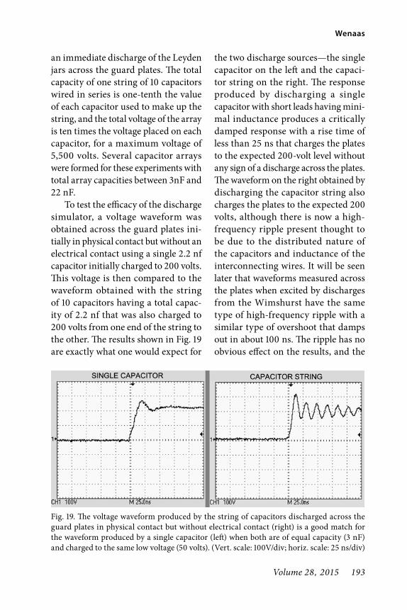
Volume 28, 2015 193
Wenaas
an immediate discharge of the Leyden jars across the guard plates. The total capacity of one string of 10 capacitors wired in series is one-tenth the value of each capacitor used to make up the string, and the total voltage of the array is ten times the voltage placed on each capacitor, for a maximum voltage of 5,500 volts. Several capacitor arrays were formed for these experiments with total array capacities between 3nF and 22 nF.
To test the efficacy of the discharge simulator, a voltage waveform was obtained across the guard plates ini-tially in physical contact but without an electrical contact using a single 2.2 nf capacitor initially charged to 200 volts. This voltage is then compared to the waveform obtained with the string of 10 capacitors having a total capac-ity of 2.2 nf that was also charged to 200 volts from one end of the string to the other. The results shown in Fig. 19 are exactly what one would expect for
the two discharge sources—the single capacitor on the left and the capaci-tor string on the right. The response produced by discharging a single capacitor with short leads having mini-mal inductance produces a critically damped response with a rise time of less than 25 ns that charges the plates to the expected 200-volt level without any sign of a discharge across the plates. The waveform on the right obtained by discharging the capacitor string also charges the plates to the expected 200 volts, although there is now a high-frequency ripple present thought to be due to the distributed nature of the capacitors and inductance of the interconnecting wires. It will be seen later that waveforms measured across the plates when excited by discharges from the Wimshurst have the same type of high-frequency ripple with a similar type of overshoot that damps out in about 100 ns. The ripple has no obvious effect on the results, and the
Fig. 19. The voltage waveform produced by the string of capacitors discharged across the guard plates in physical contact but without electrical contact (right) is a good match for the waveform produced by a single capacitor (left) when both are of equal capacity (3 nF) and charged to the same low voltage (50 volts). (Vert. scale: 100V/div; horiz. scale: 25 ns/div)

194 The AWA Review
Oliver Lodge’s Fanciful History of the Coherer Principle
capacitor string simulation technique is deemed to be acceptable for all test results reported in this effort.
Spark-Discharge Coherence in the Light-ning-Guard PlateThe objective of the experiments described next was to determine if the two guard plates initially in physical contact, but in an open-circuit state, could be made to cohere—and if so, to determine the voltages and stored energies in the capacitor string required to produce coherence. The tests cov-ered a range of voltages and capacities corresponding to voltage and capacity values in the general range that Lodge described for his lightning-guard experiment. All tests were instrumented with the digital storage oscilloscope to record the voltage waveforms across the plates for selected voltages between 450 and 5,500 volts and capacitor strings ranging from 3 to 22 nF. In all cases, the guard plates were brought together until they were in physical contact but without any electrical contact, which was established by measuring the resis-tance before each discharge event. The capacitor string was then discharged across the plates and the final resistance of the plates was measured to determine if there was any permanent coherence. There was a distinct thrill the first time I observed persistent coherence pro-duced by a spark discharge from the capacitor string.
A large number of interesting results were obtained using a capaci-tor string of 3 nF total capacity charged to 5,000 to 5,500 volts, a configuration
which is referred to hereinafter as the baseline string capacitor configuration. The following test results presented here are representative of all tests per-formed, and provide a great deal of insight into the phenomenology of spark-discharge coherence. The base-line waveform was first established for the open circuit voltage by discharging the capacitor string across the guard plates that were spread apart just far enough to preclude a spark discharge. The resulting waveform shown in Fig. 20 consisted of an initial voltage spike rising to a peak of 7,000 volts in 20 ns, which then decayed to 5,000 volts in less than 500 ns.
The voltage waveform measured across the plates for a case where a high-voltage spark discharge produced breakdown but did not result in perma-nent coherence is shown on the left side of Fig. 21. The applied voltage caused a
Fig. 20. A baseline waveform was first estab-lished for the open-circuit voltage produced by discharging the 3 nF capacitor string charged to 5,000 volts when the guard plates were spaced far enough preclude a spark dis-charge across the plates. (Vert. scale: 2 kV/div; horiz. scale: 50 ns/div)

Volume 28, 2015 195
Wenaas
breakdown in less than 10 ns such that peak voltage reached only 1200 volts before dissipating across the break-down, and a small spark was observed between the plates of the size that Lodge characterized as a “scintilla.” The resis-tance across the plates after the dis-charge was measured and found to be essentially infinite, indicating the pulse did not produce permanent coherence. However, on the very next pulse with all conditions being the same, the voltage across the plates shown on the right side of Fig. 21 reached only slightly more than 500 volts and there was no vis-ible spark. In this case, the plates were found to be short-circuited with a resis-tance reading of zero on a Simpson 260 ohmmeter. The peak voltage across the plates when spark-discharge coherence occurred was less than half that when there was no coherence, but in both cases the time required for the charge to dissipate, about 300 ns, was virtually identical. It should be noted that the
plates remained short-circuited until the device was tapped, at which point the plates returned to an electrical open circuit. The plates always returned to an open-circuit state after tapping—never to a state of finite resistance such as one would expect after tapping a coherer.
In the next test sequence, the guard plates were initially put into the low-resistance coherer state prior to dis-charging the capacitor in order to compare it with the results obtained for the plates initially in an open-circuit state. A low-resistance coherer state of 5 ohms was achieved—sufficiently high to preclude a bell from ringing had it been in the guard-plate circuit with a 1.6-volt battery. The capacitor string charged to 5,000 volts was dis-charged across the plates, and resis-tance measurements taken after the pulse confirmed the plates were in a permanent short-circuit configura-tion. The resulting voltage waveform for this case is shown on the right side
Fig. 21. Peak voltages across guard plates are significantly reduced when a 5,000-volt capaci-tor string discharge results in spark-discharge coherence (right) as compared to when no coherence occurs (left). (Vert. scale: 500V/div; horiz. scale: 50 ns/div)

196 The AWA Review
Oliver Lodge’s Fanciful History of the Coherer Principle
of Fig. 22. It is of particular interest to compare this waveform with the waveform produced by spark-discharge coherence of the plates in the open cir-cuit configuration. To facilitate that comparison, the waveform resulting from permanent coherence of the ini-tially open-circuited plates is shown on the left of Fig. 22 (which is the same as the one on the right side of Fig. 21, only rescaled to match the waveform on the right).
It is startling to see that the two waveforms are virtually identical. The implication is quite clear. It has already been shown that it is impossible to dis-tinguish between the guard plates ini-tially in an open-circuit state versus initially in a coherer state using only a high-voltage pulse and the battery-bell circuit of the type Lodge used. However, the identical time evolution of the voltage across the plates for the two cases imply that the underlying
physics for the two cases is the same. In other words, it appears that the spark-discharge coherence effect dominates or “overrides” the coherer effect, and that the only effect that occurs when high-voltage capacitors are discharged across the guard plates is the spark-discharge coherence effect.
It should also be noted that, inde-pendent of the initial state of the plates, if the high-voltage discharge produces coherence at all, the coherence will always be a complete short-circuit. Furthermore, tapping the plates after achieving persistent coherence always returned the plates to an open circuit state, never a state with a measurable conductivity. Since the test results using high-voltage pulses are identical, inde-pendent of whether the plates are in a coherer state or open circuited, it is very clear that one cannot determine the initial state of the plates from tests using only high-voltage pulses.
Fig. 22. Voltage waveforms produced by spark-discharge coherence are virtually identical whether guard plates are initially in physical contact without electrical contact (left) or in the coherer mode with imperfect electrical contact (right). (Vert. scale: 200V/div; horiz. scale: 50 ns/div)

Volume 28, 2015 197
Wenaas
Energy Dependence of Spark-Discharge CoherenceA series of tests were performed to determine the energy thresholds required to produce spark-discharge coherence effects. The main thrust of this effort was to demonstrate that the threshold for producing coherence was dependent on energy rather than voltage. Tests performed at voltages of 450, 3,500 and 5,000 volts were used to demonstrate that any voltage above the breakdown threshold of the guard plates will produce coherence if there is sufficient energy stored in the capacitor at that voltage—that is, if the capacity is sufficiently large. Energy thresholds are characterized here by the initial energy stored in the capacitor, even though the phenomenology in the spark-discharge region between the plates depend on the energy deposited there rather than the energy initially stored in the capacitor. There is no easy way to measure the energy deposited because there is always a sizeable spark in the external circuit that radiates an unknown amount of energy away from the plates as the capacitor discharges. Because spark-discharge coherence
does not always occur with every pulse, the threshold is characterized somewhat arbitrarily by the stored energy required to produce the effect in at least one out of five sequential discharges. It appears from the mini-mal data taken here that the threshold characterized by the energy stored in the discharging capacitor is useful for predicting the onset of spark-discharge coherence.
The data to support the above asser-tions are shown in Table 3 for two types of capacitors: capacitor strings with capacities and voltages similar to those found in Lodge’s experiment, and individual capacitors charged to 450 volts, which is slightly above the highest breakdown threshold observed for the guard plates. For the capaci-tor strings, the capacitors were fixed and the voltages were varied to deter-mine the thresholds. For the individual capacitors, the voltage was fixed at 450 volts and the capacities were varied to determine the thresholds. Also, at 450 volts, the capacity was increased until incipient mechanical welding was observed, which was judged to have occurred when the rotation of one
Table 3. Energy thresholds for producing spark-discharge coherence and incipient welds.

198 The AWA Review
Oliver Lodge’s Fanciful History of the Coherer Principle
guard plate back and forth caused the other plate to rotate back and forth.
Incipient arc discharge welding produces significant damage to the plate surface as compared to electrical coherence. To limit damage to the plate surface, only a very few data points were taken with energies sufficient to pro-duce incipient discharge arc welding (see Fig. 23), and those data were taken late in the test program to help preserve the integrity of the plates. The majority of data taken did not leave any marks on the plates. It is interesting to note that Lodge characterized his parallel plate lightning-guard as a single-contact coherer, when in fact there are actually multiple contact points on a micro-scopic scale between the two electrodes of any single-contact coherer. However, when discharges were observed, they were always observed to occur at a sin-gle point, and so it appears that any two electrodes cohere at a single point even
though there may be multiple points of physical contact.
A number of conclusions can be drawn from this limited data. First, spark-discharge coherence can be pro-duced at any voltage above the break-down threshold of the plates in physical contact but with no electrical contact. Second, the stored energy threshold to produce coherence is on the order of 0.05 to 0.1 joules for a large range of voltages and capacities. Third, the phenomenon of spark-discharge coher-ence is a precursor to mechanical welds. Fourth, the energy threshold required to produce actual mechanical welds is about two orders of magnitude greater than that required to produce electri-cal coherence. Last, spark-discharge coherence is a distinctly different effect from the classic coherer principle—not the same principle appearing at higher voltage levels. The major differences between the two effects are summa-rized in Table 4.
Spark-Discharge Coherence in a Plate/Battery/Bell CircuitThe next series of bench tests were designed to determine the response of the bell when the bell and battery are placed in a circuit with the lightning-guard, and high-voltage pulses are applied to the guard plates. The objec-tive was to determine the conditions under which the applied pulse could make the bell ring, if any. Tests of the guard plates with the battery and bell in series with the plates were essen-tially the same as those described in the foregoing paragraphs. As before,
Fig. 23. A photograph of one guard plate taken at the end of the extensive test program pro-vides physical evidence of damage produced by the larger pulses applied to the plates.

Volume 28, 2015 199
Wenaas
the tests with battery and bell were performed with the plates initially in an open-circuit or non-coherer mode, followed by tests with the plates in the low-resistance coherer mode. Recall that it is not possible to put the plates in the high-resistance coherer mode with a 1.6-volt battery and a low-resistance bell.
The first tests were performed with the plates of the replica guard initially in an open-circuit mode with no electri-cal contact. Spark discharges occurred whenever the voltage exceeded 300 to 400 volts, but the bell did not ring until the applied voltage reached 4,500 to 5,500 volts. Even at 5,500 volts the bell did not always ring. Sometimes the bell would ring at every contact of the capacitor and sometimes it would not ring at all. Bell-ringing at 4,500 volts required locating a “sweet spot” on the plates. It is likely that the thresh-old of bell-ringing depends upon the roughness of the plates and the type and thickness of the dielectric layer on the plates. It may also depend on
other factors such as the friction of the rods holding the plates and even the humidity. A number of experiments were performed with polished spherical knobs to determine the sensitivity of the bell-ringing threshold to different surface conditions. The bell was found to ring consistently for polished spheri-cal knobs at applied voltages as low as 2,000–3,000 volts. Because Lodge never made any statement about the condition of his plates, the bell-ringing threshold for his guard plates could have been lower than the 4,500 to 5,500 voltage range measured for the lightning-guard with oxidized plates.
The measured voltages across the plates at early times were unaffected by the presence of the battery and bell due to the large inductance of the bell coil, which prevents any appreciable current flowing through the bell circuit during the first 100 nanoseconds. However, the voltage waveforms across the bell are of some interest. Voltage waveforms across both the guard plates and the bell
Table 4. Comparison of parameters characterizing both the classic coherer effect and spark-discharge coherence.

200 The AWA Review
Oliver Lodge’s Fanciful History of the Coherer Principle
were measured simultaneously with the dual-trace oscilloscope. A typical wave-form for the case where the high-voltage pulse causes the bell to ring is shown in Fig. 24. The top trace is the high-voltage pulse, although it cannot be seen in the trace because the of the long time base of 25 ms per division, which was selected to observe and record the volt-age across the bell. The scope cannot resolve very short pulses on a time scale of nanoseconds with the 25 ms time scale needed to see the bell response. The scope trigger was set at 170 volts (Channel 1 at top) for the high-voltage pulse, and the scope was triggered at the point indicated by the trigger marker at the top center of the screen. The traces confirm that 1.6 volts was immediately applied to the bell at the time the high-voltage pulse triggered the scope and
remained steady at 1.6 volts well after the pulse ended. Of course, the sound of the bell conveys essentially the same information.
Spark-Discharge Coherence with Plates in Coherer ModeIn the last series of tests, the guard plates were initially placed in a low-resistance coherer mode selected to prevent the bell from ringing. The resistances of the coherer in the low-resistance state with-out bell-ringing were in the range of 7 to 10 ohms. Recall that earlier dc testing determined that any series resistance above approximately 2.5 ohms would limit the current to the point where the bell would not ring. It was also deter-mined earlier that voltage pulses larger than 5 to 10 volts when applied to plates in either the high-resistance or low-resistance coherer mode would reduce the resistance to levels below 2.5 ohms. Not surprisingly, it was found that any pulse with a voltage in excess of 5 to 10 volts would cause the bell to ring. Thus, Lodge, who reported applying only high-voltage pulses to the plates in his experiments, could not have determined or distinguished among the three possible initial states of the plates from the bell-ringing response alone. Also, he could not have deter-mined that the bell rang at any voltage less than the lowest voltage he applied, namely, a few thousand volts.
There is still one nagging problem that was not resolved in all of the bench testing performed prior to the full-scale experiment with the Wimshurst machine. Lodge reported in his original
Fig. 24. The bell begins to ring at the instant a capacitor charged to 5,000 is discharged across the guard plates in series with the battery and bell as evidenced by the voltage waveform measured by Channel 2 with a scale of 1 volt/div (lower scale) at exactly the time the 5000-volt pulse measured by Channel 1 triggers the scope (see text). (Vert. scale: 100V/div; horiz. scale: 25 ms/div)

Volume 28, 2015 201
Wenaas
observations in 1890 that the bell-ring-ing he observed was momentary and not sustained. That result is contrary to all the bench tests performed prior to the experiments with the Wimshurst machine. The bench tests provided no evidence of momentary bell-ringing and no theory by which momentary bell-ringing could occur. Tests with the Wimshurst machine described in the next section turned out to be crucial in determining whether the bell-ringing was temporary or permanent, and in explaining the dichotomy in Lodge’s two disparate descriptions.
Replication of Lodge’s 1889 Light-ning-Guard ExperimentThe ultimate method of determining what Lodge may have observed is to replicate his lightning-guard experi-ment with a Wimshurst machine and Leyden jar discharges. Since there was overwhelming evidence from bench tests that Lodge’s brass lightning-guard circuit cannot be placed in the sensitive coherer state with the battery and bell, and since his tests were almost surely performed with the lightning-guard in the open-circuit mode, that mode became the focus of the tests with the Wimshurst machine. The objectives were 1) to demonstrate that the bell would ring with the lightning-guard plate initially in the open-circuit state, 2) to determine if temporary ringing is possible, and if so, to determine the underlying reason, and 3) to help resolve the discrepancy in Lodge’s two seemly disparate descriptions of his experiments. In Lodge’s original
version of this experiment in his 1890 JIEE publication, he stated, “…the infin-itesimal spark occurs between a pair of similar brass plates, or knobs, and the short circuiting is quite temporary,” while in the later version in his 1897 “History of the Coherer Principle,” he stated, “Every time the spark occurred the bell rang, and continued ringing until the table, or some part of the sup-port of the knobs, was tapped so as to shake or jar them asunder again.”
The 16” sectorless Wimhsurst machine shown in Fig. 25 was con-structed for this experiment by PV Scientific Instruments located in Trumansburg, NY. The entire experi-ment is shown here, including Lodge’s lightning-guard circuit connected to the two 1 nF Leyden jars. Lodge did not specifically state the capacity of the Leyden jars he used in this experi-ment, but it is known that he used small
Fig. 25. This 16” sectorless Wimshurst machine with two 1 nF Leyden jars was custom-made for this project by PV Scien-tific Instruments to replicate Lodge’s 1899 lightning-guard experiment.

202 The AWA Review
Oliver Lodge’s Fanciful History of the Coherer Principle
jars for this experiment, and he often referred to his small jars as having a capacity of 1.6 nF and his large jars having a capacity of 6 nF.47 The leads from the outer surface of the two jars were attached across the plates of the mockup lightning-guard. The 1.6-volt battery and bell were also attached across the plates. This configuration shown in Fig. 26 has been discussed in some detail earlier in this article and need not be repeated again here. The machine was first operated with the guard plates spread apart far enough to preclude discharges across the plates to get the feel of the machine and the asso-ciated instrumentation, all of which is dispensed with here. The Wimshurst machine gap was adjusted to one-half millimeter using a feeler gauge before the machine was activated. First, the open-circuit voltage applied across the lightning-guard plates by the Leyden jars was measured by moving the plates apart to the point where no spark dis-charge occurred.
A typical open-circuit voltage trace
measured by the oscilloscope with a high-voltage probe is shown in Fig. 27. The source of the initial ringing could be due to the unusual way the spark discharge is triggered by using a spark discharge applied to the Leyden charge to create a “spark” switch, or it could be due to the fact that open-circuit plates do not provide any type of load to the discharging Leyden jars. In any event, the pulse quickly settles to about 5,500 volts, which appears to be the voltage across the two Leyden jars at the time they were connected to the open-circuit lightning-guard plates by the spark dis-charge from the Wimshurst machine.
Bell-Ringing ObservedNext the lightning-guard plates were adjusted by pushing them together until physical contact was made without the bell-ringing. The resistance across
Fig. 26. This series circuit consisting of a 1.6-volt battery, an ordinary call bell and a replica of Lodge’s lightning-guard plates was used throughout the test program.
Fig. 27. With the Wimshurst machine gap adjusted to 0.5 mm, the open-circuit voltage measured across the lightning-guard plates placed several millimeters apart when the Leyden jars were discharged peaked at 7,500 volts and quickly decayed to 5,500 volts in less than a microsecond. (Vert. scale: 1kV/div; horiz. scale: 250 ns/div)
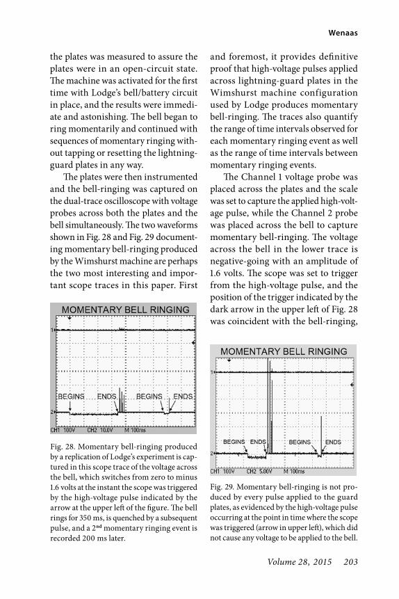
Volume 28, 2015 203
Wenaas
the plates was measured to assure the plates were in an open-circuit state. The machine was activated for the first time with Lodge’s bell/battery circuit in place, and the results were immedi-ate and astonishing. The bell began to ring momentarily and continued with sequences of momentary ringing with-out tapping or resetting the lightning-guard plates in any way.
The plates were then instrumented and the bell-ringing was captured on the dual-trace oscilloscope with voltage probes across both the plates and the bell simultaneously. The two waveforms shown in Fig. 28 and Fig. 29 document-ing momentary bell-ringing produced by the Wimshurst machine are perhaps the two most interesting and impor-tant scope traces in this paper. First
and foremost, it provides definitive proof that high-voltage pulses applied across lightning-guard plates in the Wimshurst machine configuration used by Lodge produces momentary bell-ringing. The traces also quantify the range of time intervals observed for each momentary ringing event as well as the range of time intervals between momentary ringing events.
The Channel 1 voltage probe was placed across the plates and the scale was set to capture the applied high-volt-age pulse, while the Channel 2 probe was placed across the bell to capture momentary bell-ringing. The voltage across the bell in the lower trace is negative-going with an amplitude of 1.6 volts. The scope was set to trigger from the high-voltage pulse, and the position of the trigger indicated by the dark arrow in the upper left of Fig. 28 was coincident with the bell-ringing,
Fig. 29. Momentary bell-ringing is not pro-duced by every pulse applied to the guard plates, as evidenced by the high-voltage pulse occurring at the point in time where the scope was triggered (arrow in upper left), which did not cause any voltage to be applied to the bell.
Fig. 28. Momentary bell-ringing produced by a replication of Lodge’s experiment is cap-tured in this scope trace of the voltage across the bell, which switches from zero to minus 1.6 volts at the instant the scope was triggered by the high-voltage pulse indicated by the arrow at the upper left of the figure. The bell rings for 350 ms, is quenched by a subsequent pulse, and a 2nd momentary ringing event is recorded 200 ms later.

204 The AWA Review
Oliver Lodge’s Fanciful History of the Coherer Principle
clearly indicating that the high-voltage pulse triggered the bell. The high-volt-age pulse does not appear on the trace because the time base of 100 ms set to capture the bell-ringing is too long for the scope to capture samples of the discharge pulse that lasts for only a few tens of nanoseconds. Two instances of momentary bell-ringing were cap-tured in this record, the first lasting for approximately 350 ms, stopping for 300 ms, and then momentarily ringing again for almost 40 ms.
In the second trace of Fig. 29, the high-voltage pulse that triggered the scope did not initiate bell-ringing. However, another pulse occurring 120 ms later does trigger the bell-ringing, which lasts for approximately 120 ms. A second bell-ringing episode is initiated by another pulse occurring approximately 300 ms later, and it lasts for about 20 ms, just long enough to be heard. (In separate tests it was determined that the shortest momen-tary bell-ringing that could be readily discerned by the ear was two or three bell strikes, which requires 20–30 ms.) Not every pulse from the Wimshurst machine initiates a momentary bell-ringing episode. Clearly, the coherence and decoherence from large discharges is a stochastic process with a great deal of variance.
The momentary bell-ringing con-firmed Lodge’s original version of the experiment first reported in 1890, but presented a real conundrum because momentary ringing had never been observed in the bench tests performed prior to the experiment with the
Wimshurst machine, and there was no logical explanation for momentary bell-ringing. It must be said that permanent bell-ringing was also observed from time to time, and that tapping the guard plates would stop the ringing until another pulse came along. Permanent ringing was predicted from the bench tests, although not because of coherer action but because of spark-discharge coherence of the open-circuited plates under the influence of high-voltage pulses.
Some effort was expended in attempting to determine the condi-tions under which momentary ringing was favored versus permanent ringing, but to no avail. Momentary ringing seemed to dominate but permanent ringing was not particularly rare. One could conclude that Lodge may actu-ally have observed both momentary and permanent coherence, but elected to document only momentary coher-ence because momentary coherence was inexplicable, whereas lightning often caused permanent coherence in lightning-guards. The main focus then shifted to determining the root cause of the temporary ringing. An explanation of momentary ringing was deemed to be important to avoid any doubt about conclusions drawn from the experi-mental results.
Momentary Bell-Ringing ExplainedAdditional tests were performed with high-voltage pulses using the capaci-tor strings on the bench. One day the mystery was finally solved when the capacitor string was discharged across

Volume 28, 2015 205
Wenaas
the plates while the bell was ringing, and the bell immediately stopped ring-ing. Subsequent tests demonstrated that high-voltage pulses are equally effec-tive, if not more so, in terminating spark-discharge cohesion as they are in creating it (Fig. 30). The obvious answer to the momentary-ringing conundrum observed with the Wimshurst machine is that one pulse from the machine causes cohesion between the plates by means of a spark discharge (not the coherer effect) and a subsequent pulse disrupts the cohesion. At times the ini-tial cohesion may be sufficiently strong that it is not disrupted by a subsequent pulse, while at other times the cohe-sion is disrupted by the very next pulse. Thus, the length of the momentary ringing and the spacing between the temporary ringing is variable, and also depends on the speed of the machine.
Variations in the momentary ring-ing times and spacing were observed and were consistent with the spark rates of the Wimshurst machine. At the machine speed used in all experi-ments, the spark rate was approximately 40 pulses per second for the electrode spacing of the machine at 1/50 of an inch. Thus, the time between pulses was approximately 25 ms. Momentary bell-ringing of various pulse widths were observed, and while many were longer than 25 ms, none observed was shorter. Clearly, bell coherence produced by high-voltage pulses is a stochastic pro-cess with a great deal of variability. At times, discharges of a given voltage will produce a number of consecutive coherences, and then with no obvious changes in test conditions, coherences are produced in only one out of four or five consecutive discharges.
Summary of FindingsCoherer Principle versus Spark- Discharge Coherence PrincipleThe first major finding of this effort is that there are actually two distinctly different effects that will cause cohe-sion under electrical inf luence in single-contact coherers consisting of a pair of electrodes initially in physi-cal contact—the classic coherer prin-ciple and a new principle, which has been given the name “spark-discharge coherence.” While the classic coherer mechanism produces coherence only when the electrodes are initially in both physical and imperfect electri-cal contact, spark-discharge coherence can occur when the metal electrodes
Fig. 30. Bell-ringing initiated by one pulse was terminated when a second pulse was applied to the guard plates, much as a high-voltage pulse would blow a fuse; thus the observed momentary ringing can be explained by multiple pulses produced by the Wimshurst machine.

206 The AWA Review
Oliver Lodge’s Fanciful History of the Coherer Principle
are in physical contact without any electrical contact (i.e., an open-circuit state). The only caveat is that the voltage applied across the electrically isolated electrodes must exceed the breakdown threshold of the electrodes, typically 300–400 volts. Any voltage above the breakdown threshold will produce coherence, providing there is sufficient energy in the pulse. The threshold for the energy that must be stored in the capacitor to produce spark-discharge coherence has been measured to be on the order of 0.1 joules. The underlying phenomenology involved appears to be related to capacitor discharge welding (CDW) rather than the classical coherer effect,48 although the energy threshold for producing electrical coherence is several orders of magnitude lower than the energy threshold needed to produce an incipient mechanical weld.
Sparks Plays No Part in the Coherer PrincipleThe second major finding is that con-trary to Lodge’s assertions, sparks play no part in the true coherer principle. In his 1897 “History of the Coherer Prin-ciple” publication, Lodge asserted, “The point of present interest is the cohesion which sets in between the knobs when the spark occurs: an extremely feeble spark was found sufficient to produce the effect, provided the surfaces were already almost infinitely close together, i. e., provided they were already in what would be called contact, with the mer-est imperceptible film of (probably) oxide separating them, just the kind of film which a chemical flux is useful
in removing.” He went on to say, “…the films do not really insulate, they are able however to act as dielectrics for an instant, and to be burst with what we must be allowed to call a spark, if the momentary strain caused by the impulsive rush of electricity is too great.” Lodge is referring to an impul-sive rush of electricity consisting of from 1 to 3½ volts, and says that we must be allowed to call it a spark. This is contrary to the data obtained in this effort. The continuous nature of the I–V characteristic curves for the coherers obtained clearly does not show a “burst with what we must be allowed to call a spark if the momentary strain caused by the impulsive rush of electricity is too great.”
Here is what prominent coherer experts of the day, Karl Guthe and Augustus Trowbridge, had to say in July of 1900 about Lodge’s findings:
“It can very well be conceived that if sparks really do pass, a fusion of particles may take place, and the resistance be lowered-but the question still remains, ‘Is this the action of the coherer made use of in wireless telegraphy?’ If the lowering of the resistance be due to sparking, then we can only expect a very irregular behavior of the coherer. To quote Aschki-nass who discusses Arons’ and his own results in the following words: ‘A lowering of the resis-tance takes place always when the excitation is weak, while no sparking, fusion or mechanical

Volume 28, 2015 207
Wenaas
motion can be observed at the contacts. On the other hand, with stronger excitation, sparks, etc., can be seen, while the resistance is influenced in an irregular man-ner.’49 He further states that when sparks of considerable intensity were apparent, the resistance was sometimes lowered, sometimes increased, sometimes the changes were not permanent; often sparks could be seen without any change in resistance taking place at all. From this it would appear that the phenomenon of coherer action can be best studied only when sparking is avoided. This point was thoroughly established by the quantitative experiments made by one of us a year ago50 in which a remarkable regularity in the behavior of the coherer was observed, undoubtedly due to the fact that the above condition was fulfilled.”51
In the above quote, Guthe and Trow-bridge suggest that Lodge’s observa-tions are not the “action of the coherer made use of in wireless telegraphy,” but stop short of identifying the sparking observed by Lodge as being a separate coherence principle. The results of the spark-discharge coherence experiments reported here echo the observations referenced by Guthe and Trowbridge: “when sparks of considerable intensity were apparent, the resistance was some-times lowered, sometimes increased, sometimes the changes were not per-manent; often sparks could be seen
without any change in resistance taking place at all.” The distinction between the work of Guthe and Trowbridge and this work is that they avoided sparking in order to study the classic coherer effect, whereas this effort focused on the coherence effect produced by spark dis-charges in order to quantify the effect and demonstrate that it is a different phenomenon from the classic coherer effect with a different dependence on energy and voltage.
Cause of Reported Momentary Bell-RingingThe cause of momentary bell-ringing Lodge reported in his 1889 lightning-guard experiment was an enduring mystery until the cause was found to be a second high-voltage pulse following a previous high-voltage pulse that pro-duced coherence. The second pulse has the effect of quenching the coherence much as a high-voltage pulse blows out a fuse. Thus, one of the pulses applied by the Wimshurst in rapid succession will cause the bell to ring, and then one of the subsequent pulses will cause the bell to stop ringing. The time of the momentary bell-ringing is determined by the applied pulse rate; for conditions corresponding to Lodge’s experiment, the time of momentary bell-ringing was observed to be as short as 25 ms and as long as 300 ms. The time interval between successive momentary bell-ringing episodes was generally less than 1–2 seconds.
Decoherence of two metal elec-trodes by a high-voltage pulse always resulted in an open circuit—never a

208 The AWA Review
Oliver Lodge’s Fanciful History of the Coherer Principle
poorly conducing connection like that observed with the classic coherer. Thus, a sequence of momentary pulses of the type observed here and reported by Lodge cannot possibly be caused by the classic coherer mode because the electrodes are always in an open cir-cuit state after the bell stops ringing as a result of the previous pulse that extinguished the coherence. The obvi-ous conclusion is that the momentary bell-ringing that Lodge observed can-not possibly be obtained with the classic coherer effect.
Lodge Did Not Observe the Coherer Effect in 1889It is clear from the previous paragraph that Oliver Lodge actually observed spark-discharge coherence in his 1889 lightning-guard experiment—not the classic coherer effect—primarily because the momentary short-circuit contacts between electrodes that pro-duce the momentary bell-ringing he reported cannot be produced by the coherer effect. Even if he had observed permanent bell-ringing on occasion and simply failed to report it, the permanent cohesion he would have observed could not have been the classic coherer effect for several reasons. First, it has been clearly demonstrated that coherence by the classic coherer effect cannot be distinguished from coherence produced by the spark-discharge coherence effect when only high-voltage pulses of the type Lodge used are applied. When high-voltage pulses are applied to the plates, the circuit responses and the oscilloscope traces of the voltage across
the coherer were identical whether the plates were initially in the open-circuit state (i.e., a non-coherer mode) or in light contact (i.e., a coherer mode). In essence, spark-discharge coherence will, in effect, “override” the coherer effect. Second, Lodge never reported any measurements to determine whether or not the guard plates were in the coherer mode prior to applying electrical excitations, and it is impos-sible to distinguish a coherer state with imperfect contact from open-circuit or short-circuit states with only the bell that Lodge used as an indicator of the initial and final state of the plates. Third, it was impossible for Lodge to put the guard plates in the sensitive coherer state with a 1.6-volt battery in series with a low-resistance bell. Thus, Lodge could not have observed a tran-sition from the sensitive state to the insensitive state—an absolutely neces-sary condition to discover or demon-strate the existence of the coherer effect.
Lodge’s Deception was IntentionalThere is no question that Lodge made substantive changes in the description of his lightning-guard experiment in his “History of the Coherer Principle” published in 1897 as compared to the original version published in the JIEE in 1889. With regard to bell-ringing, he stated in the original: “…the infini-tesimal spark occurs between a pair of similar brass plates, or knobs, and the short-circuiting is quite tempo-rary,” and also, “the bell only provides momentary conducting contact.” Com-pare that with the revisionist account

Volume 28, 2015 209
Wenaas
in 1897: “Every time the spark occurred the bell rang, and continued ringing until the table or some part of the sup-port of the knobs, was tapped so as to shake or jar them asunder again. ¶” The symbol “¶” is a reference to p. 352 of his original description in the Journal of the JIEE. In a single stroke of the pen, Lodge changed his original 1889 observation that “the bell only proves momentary conducting contact” to his observation in his 1897 “History of the Coherer” that “the bell rang, and continued ring-ing.” The two accounts are mutually exclusive, and worse yet Lodge never mentioned or explained this change to his account—clear evidence that his deception was purposeful.
Lodge also changed the observation in his original 1890 article that “the spot of light [on the galvanometer] disap-pears; only to be recovered by tapping the instrument” to: “some part of the support of the knobs, was tapped so as to shake or jar them asunder again.¶” The footnote ¶ refers to page 352 in “History of the Coherer Principle,” where the only reference to tapping is “tapping the instrument” when the galvanom-eter was in the circuit. However, when the galvanometer was in the circuit, there was never a battery in the cir-cuit, so there could not have been any current flowing in the circuit after the applied pulse decayed. Consequently, no amount of tapping of the guard plates could possibly have changed the position of the needle of the galva-nometer. That could be achieved only by tapping the galvanometer case. In the original description there is no
reference whatsoever to tapping the plates or knobs of the lightning-guard. Lodge tried to capitalize on the original phrase “tapping the instrument” by leading the reader of his “History of the Coherer Principle” to believe the instrument he tapped was the guard plates or knobs, a deception that was clearly intended.
The Larger Historical ContextThe cynic might say that whatever changes Lodge made to his original observations in his 1889 lightning-guard experiments, calling attention to them at this late date is just a tem-pest in a teapot because history has credited Branly for discovering the metal-filings coherer that was used in early radiotelegraphy, and Oliver Lodge never claimed precedence over Branly for discovering the metal-filings coherer. However, such a view misses the point entirely—which is that Lodge claimed priority for so much more than he was entitled to claim, and there is virtually no documentation to support his expansive claims—yet historians continue to credit Lodge with these discoveries based on his word alone. It has already been determined that Lodge’s claim to transmitting tele-graphic messages at the Oxford meet-ing in October of 1894 is not true. It is now clear from the results of this effort that Lodge altered his observations and made intentionally false claims about his discovery of the coherer principle, the single contact coherer, and the means of detecting electromagnetic waves by means of the coherer, which,

210 The AWA Review
Oliver Lodge’s Fanciful History of the Coherer Principle
as an aside, makes it much easier to accept the fact that his repeated claims of transmitting signals in Morse code at Oxford were equally false.
These false claims raise a much more important question, “Did Lodge contribute substantively to the dis-covery of the coherer and its applica-tion to early radiotelegraphy prior to the disclosure of Marconi’s system of telegraphy in 1897 as he and others claimed, or did he merely popularize the coherer in his demonstration lec-tures at the Royal Institution and the British Association in Oxford in 1894 by repeating experiments that had been developed and documented by others earlier—specifically Branly? A com-parison of the experiments Branly per-formed in 1890 and 1891 with Lodge’s work documented in Work of Hertz in 1894 reveals that, with the possible exception of Lodge’s vision experiment, most of the experiments and results Lodge published in his 1894 Work of Hertz involving coherers were actually published three to four years earlier by Branly in 1890–91 (see Table 5).52
Lodge is also generally credited as the first to use the coherer as a detector to characterize the optical properties of electromagnetic waves, which he first demonstrated at his June 1, 1894 lecture at the Royal Institution. How-ever, Branly compatriots Alexander Le Royer and Paul van Berchem pre-sented a paper at the College of Geneva in April 1894 where they reported a technique for measuring the peaks and nodes of EM waves using Bran-ly’s metal-filings coherer in order to
determine quasi-optical properties of EM radiation waves such as the wave-length.53 It is clear from the dates of presentations and publications that the French team had priority over Lodge for demonstrating that the coherer could be used to measure quasi-optical prop-erties of electromagnetic waves. Lodge never acknowledged this work of Le Royer and van Berchem despite their complaints in the literature that Lodge ignored their precedence.54 As a result, the work of Le Royer and van Berchem is largely unknown in English speaking countries to this day.
The only unique experiment using the coherer that Lodge presented in Work of Hertz was a vision experiment where he likened the response of the eye exposed to light to the response of a metal-filings coherer exposed to Hertz-ian waves. In this experiment he used a coherer with a mechanical tapper-back device driven by a clockwork mecha-nism to serve as a detector of Hertzian waves. Lodge chose a constant tapping rate of 10 taps per second based on his view of how the eye functioned: “In the eye model the period of mechanical tremor should be, say 1/10th so as to give the right amount of persistence of impression.” The mechanical tapper kept the coherer sensitive when Lodge transmitted a train of pulses, which kept the galvanometer needle deflected, thereby simulating persistence of vision. Lodge attempted to morph this experiment from a demonstration of how the eye might respond to light into a demonstration of wireless telegra-phy by claiming that the long and short

Volume 28, 2015 211
Wenaas
pulses he sent to demonstrate persis-tence of vision were actually telegraphic signals representing letters of the Morse code.55 Branly actually demonstrated essentially the same thing by tap-ping his coherer, presumably by hand, while applying long and short electrical stresses. He writes, “The restoration of resistance by shock was not observable so long as the electrical influence was at work.”56 What Branly was saying is that as long as electrical influence was being applied, the repeated shock (presumably by tapping) would not restore the resistance of the coherer to its original sensitive state. That is exactly what Lodge demonstrated in his vision experiment three years later.
Of all the work on the coherer that Branly published in 1890–91, Lodge credited Branly only for the
metal-filings coherer, and even then, he did so begrudgingly by writing: “In 1893 I heard of Branly’s filings-tube—an independent discovery, which really constituted an improvement on the first rough coherer idea [i.e., Lodge’s discov-ery].” Given the following facts, Lodge’s claims and actions were less than hon-orable, to say the least: 1) Branly pub-lished nine papers between 1890 and 1893 on the coherer that presented a number of unpublished demonstration experiments with a variety of coherer types and materials resulting in many new observations about how the coherer worked, 2) Lodge published absolutely nothing about the coherer principle or how the coherer works until 1894,57 3) almost all of the experiments and results Lodge published on coherers in his 1894 Work of Hertz were discovered
Table 5. Branly’s coherer demonstrations, coherer types, and coherer observations published in 1890–1.

212 The AWA Review
Oliver Lodge’s Fanciful History of the Coherer Principle
and published by Branly three years prior (see Table 5), 4) Lodge stated that well before his 1894 demonstra-tion lectures he had read the abstract of Branly’s work published in the July and August 1891 issues of The Electrician,58 which contained a rather complete synopsis of Branly’s most important results, 5) Lodge referenced Branly only once in his 1894 book of Work of Hertz, where he credited Branly for the metal-filings coherer on page 21, and 6) Lodge in his later writings explicitly stated that many of the experiments he published on the coherer in Work of Hertz were new.59
As a result, Branly went unrecog-nized as the inventor of the radio-con-ductor for many years even in his own country until he was finally awarded the Houllevigue prize from the French Academy of Sciences in December of 1898 for his discovery of the radio-conductor: “…the bestowal of the prize on M. Branly is all the more deserv-ing because the tendency has been to rob that gentleman of his due on the grounds that his most important dis-covery (the property of radio-conduc-tors) belongs by priority to a foreigner. His right to the honor of having been the first to make the discovery is thus officially established by the académie.”60
Not to be outdone, the Royal Soci-ety of London awarded Oliver Lodge the prestigious Rumford Medal a few months later in March of 1899, in part for his discovery and introduction of the coherer: “Professor Lodge’s intro-duction of the ‘coherer’—an instru-ment the action of which is based on
observations made independently by himself and M. Branly—as a sub-stitute for the Hertz ‘resonator’ has increased in a marked degree the facil-ity for reproducing and extending the experiments of Professor Hertz, and has furnished the means of exhibiting much more conspicuously the result obtained.”61 It was generally accepted in the UK that Lodge had discovered the coherer principle in 1888–9, almost a year before Branly, which meant that Lodge was officially accorded priority over Branly for discovering the coherer. Lodge was never questioned by English scientists about the substantive changes and discrepancies in his observations of the single experiment supporting his claims of priority—despite claims in the French press that Branly, Le Royer and van Berchem collectively had paternity for much of that for which Lodge had claimed priority.62
One lingering question remains, “How did all of Lodge’s false claims go unnoticed by his contemporaries and by most historians that followed?” This is a subject best left for another treatise, but there are a number of obvious fac-tors. First, Lodge was a Fellow of the Royal Society and a respected profes-sor at University College, Liverpool, so his pronouncements were readily believed without the documentary evidence generally required of those not firmly entrenched in the estab-lishment. Second, there was scientific competition between countries at the time with national pride at stake, and so Lodge’s contemporaries circled the wagons around Lodge to defend his

Volume 28, 2015 213
Wenaas
claims of discoveries in the field of wire-less telegraphy against those of foreign-ers such as Marconi and Branly, who were perceived to be interlopers. Third, the coherer was an esoteric device, and judging by contemporary publica-tions, few scientists in the UK had any knowledge of the coherer, and no UK scientist was in any position to seri-ously question Lodge’s work. Fourth, Lodge was well aware of ongoing work by others on the subject of coherers, but he rarely if ever referenced their work—and when he did, it was usually accompanied by dismissive comments. Lodge in particular ignored the coherer work of others published in foreign lan-guages, and these works were rarely translated into English. Thus, Lodge’s fanciful account of “The History of the Coherer” has been generally accepted in English speaking countries without critical examination.
Notes1. A single-contact coherer refers to two
metallic electrodes that make physical contact but imperfect electrical contact (typically tens of ohms to a few thou-sand ohms) in the sensitive state and rapidly transitions to a low-resistance or insensitive state (typically 1 to 10 ohms) when low voltages (typically between 0.05 to 0.8 volts) are applied across the electrodes. In contrast, the metal-filings coherer, while less sensitive than the single-contact coherer, is more reliable and repeatable than the single-contact coherer. For that reason it was used exclusively in early radiotelegraphy.
2. O. Lodge, Past Years, An Autobiography
by Sir Oliver Lodge, (Charles Scribner’s Sons, New York, 1932); Advancing Science, (Ernest Ben Ltd., 1931); Talks About Radio, (George H. Doran Co., New York, 1925).
3. S. Hong, Wireless, From Marconi’s Black-Box to the Audion, (MIT Press, Cam-bridge, MA, 2001).
4. E. P. Wenaas, “Researching the Real Inventor of Radio Telegraphy,” AWA Journal, Autumn 2013, Vol. 54, pp. 48–53, 60.
5. Report from the Select Committee on Radio Convention, Wyman & Sons, Vol. 8, July 8, 1907, p. 157.
6. O. Lodge, “Hertzian Waves,” Electri-cal Engineer (London), Vol. 14, Aug. 24, 1894, pp. 212-3.
7. Charles Süsskind, “The Early History of Electronics, III. Prehistory of Radiote-legraphy,” IEEE Spectrum, April 1969, p. 72. While Susskind did not give a specific reference to Lodge’s claim, the following is a statement by Lodge on the subject that appears in his autobi-ography: “For instance, when I had dis-covered the means of detecting electric waves [from a spark] by means of the coherer, the late Lord Rayleigh said to me, ‘Well, now you can go ahead; there is your life work!’”
8. A. Frederick Collins, “The Genesis of Wireless Telegraphy,” Electrical World and Engineer, Vol. 39, May 10, 1902, p. 811.
9. J. A. Hill, Letters from Sir Oliver Lodge, (Cassell & Co., London, 1932) p. 47.
10. O. Lodge, “Electrical Signalling with-out Connecting-Wires,” Proc. Phys Soc. London, Vol. 16, 1898, pp. 58-59; read on Jan. 21, 1898.
11. O. Lodge, Past Years, p. 113.

214 The AWA Review
Oliver Lodge’s Fanciful History of the Coherer Principle
12. Munck, P. S. (1835), Versuche über die Fähigkeit starrer Körper zur Leitung der Elektricität. Ann. Phys., 110: 437–463. doi: 10.1002/andp.18351100304; Munck, P. S. (1838), Untersuchungen über Ele-ktricität, mit besonderer Rücksicht auf die Theorie der galvanischen Kette. Ann. Phys., 119: 193–227. doi: 10.1002/andp.18381190202.
13. T. Calzecchi-Onesti, “Conductivity of Metal Filings,” Il Nuovo Cimento,” Vol. 16 1894, p. 58–64; “Conductivity of Metal Filings ~ 2nd Note;” Il Nuovo Cimento, Vol. 17, 1885, pp. 38–42.
14. S. A. Varley, “Lightning and Telegraph Wires,” Journal of the Telegraph, Vol. 5, No. 5, Feb. 1, 1871, pp. 53–55; paper read before Section A of British Association at Liverpool in 1870.
15. D. E. Hughes, “Prof. D. E. Hughes’s Researches in Wireless Telegraphy,” Elec-trician, Vol. 43, May 5, 1899, pp. 40–41; J. Munro subsequently visited David Hughes and published a more detailed abstract of his experiments: “The Experi-ments of Prof. Hughes on Ether Telegra-phy,” Electrical Review, Vol. 44, June 2, 1889, pp. 883–885.
16. D. Turner, “On M. E. Branly’s Experi-ments on Electrical Resistance,” Report of the 62nd Meeting of the British Asso-ciation for the Advancement of Science held at Edinburgh in August 1892, (John Murray, London, 1893) p. 637; presented Aug. 5, 1892.
17. W. B. Croft, “Two-Lecture Room Experiments,” Proc. Phys. Soc., Vol. 12, Oct. 1892 to Jan 1894, p. 421; exhibited Oct. 27, 1893.
18. O. Lodge, Wireless Weekly, Sept. 26, 1923, p. 412.
19. G. M. Minchin, “The Action of Electro-magnetic Radiations on Films Contain-ing Metal Particles.” London, Edinburgh, & Dublin Phil. Mag. and J. of Sci., Vol. 37, Jan. 1894, pp. 90–94; read Nov. 24, 1893.
20. O. Lodge, “On the Sudden Acquisition of Conducting-Power by a Series of Discrete Metallic Particles,” London, Edinburgh, & Dublin Phil. Mag. and J. of Sci., Vol. 37, Jan. 1894, pp. 94–95; read Nov. 24, 1893.
21. O. Lodge, Work of Hertz and Some of His Successors, (Electrician Publishing, London, 1st ed. Sept. 1894) p. 22.
22. Ibid., p. 21.23. G. Marconi, “Improvement in Transmit-
ting Electrical Impulses and Signals, and Apparatus Therefore,” UK Patent No. 12,039; Date of Application, 2nd June 1896; Accepted, 2nd July 1897.
24. E. Branly, “Electrical Conductivity of Insulating Bodies,” Le Cosmos, Vol. XXIV, 1893, pp. 20–21.
25. E. Branly, Variation of Conductivity of Insulating Substances, Le Cosmos, Revue des Sciences, Vol. XVIII, 4 th Quarter, 1891, pp. 395–8.
26. W. H. Eccles, “Some Experiments on Filing Coherers,” Electrician, Vol. 27, Aug. 23, 1901, p. 683.
27. E. Branly, Le Cosmos, 1891, p. 396.28. E. Branly, “Variation of Conductivity
under Electrical Influence,” Electrician, June 26, 1891, p. 221.
29. O. Lodge, JIEE, 1890, p. 352–354.30. O. Lodge, “The History of the Coherer
Principle,” Electrician, Vol. 40, Nov. 12, 1897, pp 87–91.
31. W. H. Preece and A. J. Stubbs, A Manual of Telegraphy, (Whittaker & Co., Lon-don, 1893) p. 116.

Volume 28, 2015 215
Wenaas
32. O. Lodge, JIEE, 1890, p. 409; in the dis-cussion following the lecture, Lodge thanked Mr. Wimshurst for providing his machine for the experiments.
33. Oliver Lodge, “Protection of Buildings from Lightning,” Electrician, Vol. 21, June 29, 1888, p. 234.
34. H. Mason, A Text-Book on Static Electric-ity, (McGraw Publishing Co., New York, 1904) p. 140.
35. O. Lodge, The Work of Hertz and Some of His Successors, pp. 21–22.
36. O. Lodge, Times (of London), June 17, 1894; reproduced in O. Lodge, “Teleg-raphy without Wires,” Electrical Review, Vol. 40, June 25, 1897, p. 891.
37. O. Lodge, JIEE, 1890, p. 351, lines 1 and 12 in Paragraph 10.
38. Ibid., p. 352, Experiment No. 4, line 3.39. Ibid., p. 355, Paragraph 14, line 1.40. W. Watson, A Text Book of Practical
Physics, (Longmans, Green and Co., London, 1913) p. 425.
41. H. R. Kempe, A Handbook of Electrical Testing, (E. &, F. N. Spon, London, 1892) p. 100.
42. S. R. Bottone, Electric Bells and All About Them, (Whittaker & Co., London, 1889) pp. 144–145.
43. A. E. Kennely, Inductance and the Pro-posed Unit the Henry, Electrical Engi-neer, Jan 9, 1891, Vol. 7, pp. 43–44.
44. J. C. Bose was perhaps the first to meas-ure what he called Conductivity Hys-teresis in the I-V characteristics of an iron filings coherer; see J. C. Bose, “On the Change of Conductivity of Metallic Particles Under Cyclic Electromotive Variation,” Electrician, Vol. 47, Sept. 27, 1901, p. 879.
45. The capacitors must be chosen so the RC
time constant is large enough to prevent premature bleed off across the resist-ance of the coherer, but not so large that the resulting discharge current gener-ates enough heat at the junction of the coherer to impact the final resistance.
46. K. E. Guthe, “On the Action of the Coherer,” Phys. Rev., Vol. 12, 1901, p. 246.
47. O. Lodge, “Experiments on the Dis-charge of Lightning Jars,” Proc. Royal Soc., Vol. 50, 1892, p 2.
48. R. D. Wilson, J. R. Woodyard, Sr. & J. H. Devletian, “Capacitor Discharge Welding, Analysis Through High-Speed Photography,” Welding Research Supple-ment I 105-s, March 1993. See Internet address, https://app.aws.org/wj/supp lement/WJ_1993_03_s101.pdf?
49. E. Aschkinass, C. R., Vol. 128, p.1092, 1899; Vol. 127, p. 1014, 1898; Vol. 129, p. 40, 1899.
50. A. Trowbridge, “A Quantitative Inves-tigation of the Coherer,” Am. Jour. Sci., Sept. 1899, pp. 199-205.
51. K. E. Guthe and A. Trowbridge, “On the Theory of the Coherer,” Phys. Rev. Vol. 11, No. 1, July 1900, pp. 22–24.
52. E. Branly, nine papers on variations of conductivity published between Nov. 1890 and 1893.
——. “Variation of Conductivity Under Different Electrical Influences,” Comptes Rendus des Séances de L’Académie des Sciences, Vol. 111, 1890, p. 785; read on Nov. 24, 1890 to L’Académie des Sci-ences. Abstracted in Electrical Review, Vol. 27, Dec. 6, 1890, p.770–1.
——. “Variations of Conductivity in Insulating Substances,” Comptes Rendus des Séances de L’Académie des Sciences, Vol. 112, 1890, p. 90; read on Jan. 12, 1890

216 The AWA Review
Oliver Lodge’s Fanciful History of the Coherer Principle
to L’Académie des Sciences; abstracted in Minutes of Proceedings of Inst. Civil Engineers, Vol. CIV, 1891, pp. 416–418.
——. “Experiments of Electrical Con-ductivity, Bul. Soc. Internationale des Électriciens, Vol. VIII, 1891, pp. 196–202.
——. Variation of Conductivity of Insu-lating Substances, Le Cosmos, Revue des Sciences, Vol. XVIII, 4th Quarter, 1891, pp. 395–8; abstracted in Electrical Engi-neer, Vol. 7, March 27, 1891, p. 308.
——. “Variations of Conductivity of Insulator under Different Electrical Influences,” Compte Rendu du Con-grés Scientifique International des Catholiques,” 1-6 April 1891, pp. 116-134.
——. “Review of Recent Work in Electric-ity,” La Lumière Électrique, Vol. XL, 1891, pp. 186–187; presented April 17, 1891.
——. “Variations of Conductivity of Insulator under Different Electrical Influences,” La Lumière Électrique, Vol. XL, May 16, 1891, p. 301–309; abstracted in Electrician, June 26, 1891, pp. 221–222.
——. “Variations of Conductivity of Insulator under Different Electrical Influences,” La Lumière Électrique, Vol. XL, June 13, 1891, p. 506–511; abstracted in Electrician, Vol. 27, Aug. 21, 1891, pp. 448–449.
——. “Electrical Conductivity of Insulat-ing Bodies,” Le Cosmos, Vol. XXIV, 1893, pp. 20–21.
53. Alex. Le Royer and P. van Berchem, “Measurement of the Wavelength of Hertzian Waves in Air by a Change in the Resistance of Metal Filings” Archives des Science Physiques et Naturelles, Vol. 31, June, 15 1894, pp. 558–561; pre-sented at the College of Geneva, April 1894.
54. Editor, “On Using the Coherer or Radioconductor for Detecting Hertz-ian Waves,” Revue D’ Électricit, Vol. 15, May 28, 1898, pp. 373-375.
55. How Lodge tried to morph his 1894 vision experiment with a mechanical tapper into a telegraphy experiment, and why the mechanical tapper and marine galvanometer cannot be used for teleg-raphy is detailed in two articles: E. P. Wenaas, AWA Journal, Autumn 2013, pp. 48–53, 60; and AWA Journal, Winter 2014, pp. 34–39, 45.
56. E. Branly, Electrician, Aug. 21, 1891, p. 448.
57. It has been conclusively demonstrated here that Lodge did not observe the coherer principle in his 1889 lightning-guard experiment. The next time he mentioned coherence of any kind was in the note he wrote to be read in con-junction with Minchin’s paper, both of which were published in 1894.
58. O. Lodge, Electrician, Nov. 12, 1897, p. 89.59. For example, in Lodge’s Advancing Sci-
ence reminiscences, he states on page 89, “I took it [coherer] up again after the death of Hertz, and after Branly had discovered the filings tube, and in 1894 showed many experiments, many of them new, which in a manner were dedicated to the memory of Hertz.”
60. “The Houllevigue Prize, Electrical Review (New York), Vol. 33, Dec. 21, 1898, p. 389.
61. Year-Book of the Royal Society of Lon-don, (Harrison and Sons, London, 1899) pp. 154–156.
62. E. Sarasin, Archives des Sci. Phys. et Naturelle, Vol. 14, 1897, pp. 45–46; pre-sented Aug. 6, 1897.

Volume 28, 2015 217
Wenaas

218 The AWA Review
Oliver Lodge’s Fanciful History of the Coherer Principle

Volume 28, 2015 219
Wenaas

220 The AWA Review
Oliver Lodge’s Fanciful History of the Coherer Principle
AcknowledgmentsI would like to thank Dr. Thomas Gregory for his assistance in captur-ing a number of the waveforms pre-sented here, and for discussions on their meaning. Dr. Gregory received his Ph.D. in Experimental Physics from the University of Connecticut and spent the majority of his career developing high-speed instrumentation. I would also like to thank Jim Hardesty of PV Scientific Instruments, Trumansburg, NY, for designing and assembling the Wimshurst machine out of reclaimed antique electrostatic machine parts specifically for this project.
About the AuthorEric P. Wenaas has had a lifelong pas-sion for antique radios beginning with his first Radiola and crystal set given to him as a young man growing up in Chicago by family friends. He experi-mented with radio devices and repaired radios and televisions as a hobby while in high school, and went on to study electrical engineering at Purdue Uni-versity, graduating with B.S. and M.S. degrees in Electrical Engineering. He then went to the State University of New York (SUNY) at Buffalo where he earned a Ph.D. degree in Interdisciplin-ary Studies in the School of Engineer-ing. After graduating, he spent most of his career at Jaycor, a defense com-pany in Southern California—first as an engineer and later as the President and Chief Executive Officer.
Upon his retirement in 2002, he set out to research the early days of wireless and document interesting historical vignettes based on original documents of the era. One of his areas of specialty is the early coherer and crystal detector. He has assembled an extensive collec-tion of early coherers and detectors, and performed many experiments on both types of early wireless detection devices. He has tested most types of early coherers including metal filing tubes, point-contact electrodes of vari-ous metals, and a mercury coherer of the type used by Marconi in his trans-atlantic experiment. He published three articles on the coherer and crys-tal detector in previous issues of The AWA Review, and two articles on Oliver Lodge and his involvement with wire-less telegraphy in the AWA Journal.
Eric Wenaas

Volume 28, 2015 221
90 Years of Pre-Electronic VLF-TransmissionSAQ in the former RCA Commercial Net—an UNESCO World Heritage Site
©2015 Bengt Svensson
AbstractSAQ in Grimeton, near the town of Varberg on the Swedish west coast, is the only remaining pre-electronic transmitter in working order. It was a part of the RCA Commercial Net from October 1924, when the first message was sent to “Radio Central” at Rocky Point, Long Island.
On July 2nd 1925, the station was inaugurated by King Gustav V, sending a tele-gram to president Calvin Coolidge, praising the new link to America.
In the year 2004, UNESCO decided to put SAQ/Grimeton on the World Heritage List, with the following declaration, somewhat shortened: The Varberg Radio Station at Grimeton in southern Sweden (built in 1922–24) is an exceptionally well preserved monument to early wireless transatlantic communication. It consists of the transmitter equipment, including the aerial system of six 127-m high steel towers. Though no longer in regular use, the equipment has been maintained in operating condition. . . . The site is an outstanding example of the development of telecommunications and the only surviving example of a major transmitting station based on pre-electronic technology.
Fig. 1. RCA Commercial Net 1924.

222 The AWA Review
90 Years of Pre-Electronic VLF-Transmission
The SAQ historyThe 1920s were the era of the indus-trial race, a desire for peace between countries as well as the emigration, that became the driving force in the development of engineering. Commu-nication between Sweden and America was carried out by expensive cable ser-vice or spark stations, via Great Brit-ain. Direct radio communication was required.
In 1920 the Swedish Government decided that the Telegraph Authorities (Telegrafverket) should build a radio station to comply with the requirement. The Alexanderson Alternator-system, manufactured by GE was chosen. It was also the system used in the new
The station was in use, around the clock, until 1947 and was one of the few secure links from Europe to America during WW2, when the North Sea cables were cut. The Royal Swedish Navy also used the station for traffic to submerged submarines, in retrospect crucial for the survival of the nation.
The RCA Commercial Net was based on inventions by the Swedish-American Dr Ernst F.W.Alexanderson, chief engineer at General Electric and RCA. A total of 20 systems were manufactured by GE and two of the last were installed in Sweden during 1922–1924.
RCA Commercial Net (Fig. 1), with the Radio Central on Long Island acting as the hub of a global network, in which 18 Alternators were installed.
The Swedish transmitting station was built at Grimeton (Fig. 2), where the agricultural countryside near the coast would give the VLF-waves a great circle path over sea water to Long Island, north of Denmark and south of Norway. Building started in 1922 and was ready in 1924, after a delay caused by a strike in the Swedish iron mines.
The main building was designed by the architect Carl Akerblad in neoclas-sical style (Fig. 3) and the structural engineer Henrik Krüger was respon-sible for the 127 meter high antenna
Fig. 2. Map over the Swedish west coast, where the arrow is pointing to Grimeton.
Fig. 3. Station building in neoclassical style.

Volume 28, 2015 223
Svensson
towers, the tallest structures in Sweden at that time.
SAQ started passing messages on December 1st 1924 on the frequency 16.7 kHz (18,000 meters wavelength), later changed to 17.2 kHz (17,400 m).
When the station was officially opened by King Gustav V on July 2nd 1925, it was already known that short wave was becoming more advanta-geous. However, VLF worked well dur-ing day and night, winter and summer and during changes in sun activity. In addition, it could be used for submarine communication.
Ernst E.F. Alexanderson— A Swedish radio pioneerErnst Fredrik Werner Alexanderson (1878–1975) was born in Sweden, grad-uated at the Royal Technical Institute (KTH) in Stockholm in 1900 and then at the Technical University in Berlin-Charlottenburg, where he got a good
basic knowledge of wireless (Fig. 4). He also met with Charles P. Steinmetz and read his book ”Theory and Calcula-tion of Alternating Current Phenom-ena”. Alexanderson emigrated to the United States in 1901 and Steinmetz recommended him for a job at Gen-eral Electric in Schenectady, N.Y. There he stayed for the rest of his long and creative life, working with practically everything in electricity, from AC and DC to television and transistors. He finally became Chief Engineer at GE and RCA.
In 1919 he received the Medal of Honor from the Institute of Radio Engineers (IRE) and in 1944 the Edi-son Medal from AIEE, later to become IEEE. He was awarded honorary doc-torates from the University of Uppsala and the Royal Institute of Technology in Stockholm. He was inducted posthu-mously into the US National Inventors Hall of Fame in 1983.
Alexanderson made inventions of main importance to the early trans-oceanic communication systems.
■ Transmitter (High Frequency Alter-nator) U.S. Patent No. 1008577 (Fig. 5.)
■ Modulator (Magnetic Amplifier) U.S. Patent No. 1206643
■ Multiple Tuned Antenna U.S. Patent No. 1360168
■ Receiver (Selective Tuning System) U.S. Patent No. 1173079Through these and other inventions,
RCA became independent of the Mar-coni and de Forest patents.
At an age of 94, his 345th patent was registered.
Fig. 4. Ernst Fredrik Werner Alexanderson (1878–1975).
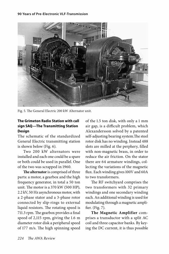
224 The AWA Review
90 Years of Pre-Electronic VLF-Transmission
The Grimeton Radio Station with call sign SAQ—The Transmitting Station DesignThe schematic of the standardized General Electric transmitting station is shown below (Fig. 6).
Two 200 kW alternators were installed and each one could be a spare or both could be used in parallel. One of the two was scrapped in 1960.
The alternator is comprised of three parts: a motor, a gearbox and the high frequency generator, in total a 50 ton unit. The motor is a 370 kW (500 HP), 2.2 kV, 50 Hz asynchronous motor, with a 2-phase stator and a 3-phase rotor connected by slip-rings to external liquid resistors. The rotating speed is 711.3 rpm. The gearbox provides a final speed of 2,115 rpm, giving the 1.6 m diameter rotor disk a peripheral speed of 177 m/s. The high spinning speed
of the 1.5 ton disk, with only a 1 mm air gap, is a difficult problem, which Alexandersson solved by a patented self-adjusting bearing system.The steel rotor disk has no winding. Instead 488 slots are milled at the perphery, filled with non-magnetic brass, in order to reduce the air friction. On the stator there are 64 armature windings, col-lecting the variations of the magnetic flux. Each winding gives 100V and 60A to two transformers.
The RF switchyard comprises the two transformers with 32 primary windings and one secondary winding each. An additional winding is used for modulating through a magnetic ampli-fier. (Fig. 7).
The Magnetic Amplifier com-prises a transductor with a split AC coil and three capacitor banks. By key-ing the DC current, it is thus possible
Fig. 5. The General Electric 200 kW Alternator unit.
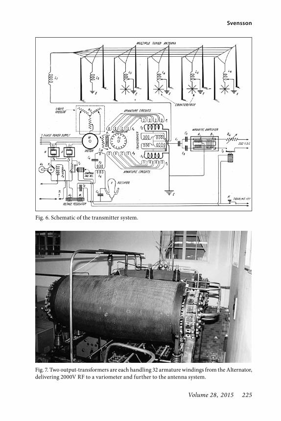
Volume 28, 2015 225
Svensson
Fig. 6. Schematic of the transmitter system.
Fig. 7. Two output-transformers are each handling 32 armature windings from the Alternator, delivering 2000V RF to a variometer and further to the antenna system.

226 The AWA Review
90 Years of Pre-Electronic VLF-Transmission
to modulate the RF inductance and thereby the resonance conditions and the RF coupling.
There is an additional winding S1 in series with the secondary winding Tr2. In parallel there is a circuit consisting of the AC coils A in the transductor and the capacitors C/C1/C2. This circuit is series-resonant, which means that its impedance varies with the frequency and has its lowest value at the resonance frequency.
At key down, there is no DC in coil B and the resonance frequency in A-C/C1/C2 is far from the transmitting fre-quency. Winding S1 feeds current to the antenna in resonance. When key is up, the relay T1 is closed and coil B gets DC and the circuit A-C/C1/C2/ becomes equal to the transmitting frequency. Thereby the winding S1 is short cir-cuited and its current passes the reso-nance circuit instead of the distuned antenna. It may seem dramatic that
the alterator becomes short-circuited at key-up. However, this is no real danger, since there is a lot of reactance in the alternator and the transformer, that keep the current at a harmless level. (Fig. 8)
The Speed Control is entirely based on the properties of an induc-tion motor. The synchronous speed is 750 rpm and a slip is proportional to the load. 711.3 rpm is the desired speed of SAQ to get 17.2 kHz.
Three factors inf luence the slip: 1. The supply voltage, 2. The rotor resis-tance, 3. The load. The highest voltage is about 2,300V. In the supply lines there are four transductors, which can keep the voltage between 1,300 and 2,300V.
The rotor resistance is varied by liq-uid resistors (diluted sodium hydrox-ide), connected by cables and slip rings. By means of sector gates, the level of liquid can be varied and thereby the resistance (Figs. 9, 10).
Fig. 8. Schematic of the magnetic amplifier, where a moderate DC controls a much stronger AC. It is a part of the antenna resonance circuit and distunes the antenna at key-up to less than 10% of antenna current.

Volume 28, 2015 227
Svensson
Fig. 9. Schematic of the speed control. The speed is controlled by variable resistors, transduc-tors and liquid resistors, which automatically compensate for varying motor load.
Fig. 10. The three liquid resistor reservoirs, in the middle, contain diluted sodium hydroxide in contact with electrodes of the drive motor windings. Gating the liquid level is changing the rotor resistance.

228 The AWA Review
90 Years of Pre-Electronic VLF-Transmission
The Antenna System is supported by six free-standing towers, 127 m tall and with 46 m wide top cross-members. The towers are spaced by 380 m and the total length is around 2,000 meters (Fig. 11).
The antenna signal exits the build-ing through a balanced two-wire cage type transmission line and a balun transformer, providing an RF voltage of 60 kV.
The top-wire system is only a trans-mission line and the antenna function is provided by the cage lines that are connected to variable inductors at each of the six towers. An essential part of the system is the grounding network (Fig. 12).
The reason for the arrangement with six radiating conductors is to
Fig. 12. The multiple tuned antenna principle (U.S. Patent No. 1360168). The top-wire system is only a transmission line.
Fig. 11. Six 127 meter (416 feet) tall steel towers, with 46 m wide cross-members, are spaced by 380 m apart. Each tower supports a verti-cal antenna.

Volume 28, 2015 229
Svensson
gain efficiency. The radiation resis-tance is about 50 milliohms and the gound resistance about 2.5 ohms and the single antenna efficiency would thus be around 2%. However, the genius of Alexanderson stepped in again. By hav-ing several radiators he could get a mul-tiple tuned antenna, in the Grimeton
case the efficiency is above 10%. The radiation pattern is almost omnidirec-tional, with a small increase in north- and southwest. The short length of the antenna, 2,200 m, compared to the wavelength, 17,400 m, is probably the reason for the weak gain. (Figs. 13, 14, 15, 16).
Fig. 13. The keying relay speed was typically 50 wpm, but the transmitter could handle up to 150 wpm. The key is cooled by air.
Fig. 14. The air pump for cooling the key and to reduce key sparks.
Fig. 15. Piping system conducts cooling water to cooled objects, like the Alternator stator.

230 The AWA Review
90 Years of Pre-Electronic VLF-Transmission
Grimeton in danger, but savedAfter 1947, SAQ faced a small chance of surviving because intercontinen-tal communications had been taken over by HF radio. However, the Royal Swedish Navy still needed SAQ and its antenna system. Unfortunately, the naval interest decreased as the North sea no longer was a priority area. In 1995, the Radio Services of Swedish Telecom, the owner, decided to close SAQ, still in perfect working order. The “last SAQ transmission” could be heard in September 1995 at the IEE London conference “A Hundred Years of Radio”. The transmission was being heard in the auditorium by courtesy of the BBC.
Due to strong pressure from radio enthusiasts the situation was totally reversed. Grimeton was listed as a National Industrial Monument in
October 1996 and after eight years of heavy work SAQ was put on the UNESCO World Heritage List on July 2nd 2004. Protected by Swedish law, the station will be kept in working order.
Royal supportOn September 5th 2001, King Carl Gustav XVI and Queen Silvia visited Grimeton and sent a message to the People of the world, keyed by Carl-Henrik Walde, SM5BF, (one of the most active driving forces in saving the sta-tion). (Fig. 17). The radiogram read:
on july 2 1925 my great grand father inaugurated grimeton radio and on january 1 2000 saq transmitted my millenium message stop today on our royal tour we send our best wishes from saq = carl gustav rex silvia regina
Fig. 16. The central control panel still in original shape.

Volume 28, 2015 231
Svensson
SAQ on the airAs a tribute to “Alex”, SAQ is on the air during the Sunday nearest the turn of the month June and July. It is called the “Alexanderson Day” (Fig. 18). About 400 reports are received from Europe and US east coast. The distance record is a report from California. Also on Christmas Eve and some other days, the station transmits a message to the world. Visitors are welcome on week-ends in May and every day during June to August. Other days on request. The operation is done by volunteers in the Alexander Society, www.alexander.n.se, for the Grimeton World Heritage, www.grimetonradio.se.
Fig. 17. The Swedish King Carl Gustav XVI and Queen Silvia visiting the World Heritage Site and watching Carl-Henrik Walde, SM5BF, keying their message to the People of the world.
Fig. 18. Ernst Alexanderson, Honorary Doc-tor at the Royal Institute of Technologi in Stockholm, Sweden.

232 The AWA Review
90 Years of Pre-Electronic VLF-Transmission
ReferencesB.V. Nilsson. “Ernst Fredrik Werner Alex-
anderson”, Grimeton World Heritage Foundation, (2006 English version); ISBN 91-766294-0-5 (Available at the AWA museum shop).
J.E. Brittain. “Alexanderson: Pioneer in American Electrical Engineering”, Johns Hopkins Univ. Press (1992); ISBN 0-8018-4228-X.
G. Brodin. “Ernst Fredrik Werner Alexan-derson”, Royal Swedish Academy of Sci-ences (IVA), (1998); ISBN 91-7082-633-1
Joakim Johansson. “The Early Days of Radio in Sweden, Ernst F.W.Alexanderson and Grimeton Radio Station SAQ”, 7th European Conference on Antennas and Propagation (EUCAP 2013).
C.-H Walde. “SAQ Grimeton”, Grimeton World Heritage Foundation, (2007); ISBN 978-91-976294-1-6.
Glen C. Fuller. “The Alexanderson System for Elecctro-Mechanical Production of Radio-Frequency Energy” (1998) The AWA Review Volume 3.
Ola Hernvall. “Grimeton Technical Manual”, Grimeton World Heritage Foundation, (2014).
Elmer E. Bucher. “The Alexanderson System for Radio Communication”, General Electric Review Vol. XXIII No 10, Octo-ber 1920.
RCA, Engineering Dept. “Description of the 200 kW Alexanderson Alternator”; Circular No. 405; “Speed Control” No. 409; “The Magnetic Amplifier” No. 424; “The Multiple Tuned Antenna” No. 425 (1924).
About the AuthorBengt Svensson, SMØUGV, BSEE, MD, CEO. Member of the AWA since 1983, and also the TCA, BVWS (England) and GFGF (Germany). Radio collector since 1970. Worked with design and project management of Air Traffic Con-trol Systems, Components engineer at Svenska Radio AB in the LM Ericsson group and finally owner of SATCO AB for 25 years, a electronic component company.
Bengt Svensson, SMØUGV.
Volume 28, 2015 233
The Heathkit DF-1 Transistor Radio Direction Finder and The DF-2 and DF-3 Models
© 2015 Erich E. Brueschke
AbstractThe Heathkit Transistor Radio Direction Finder Model DF-1 is the first kit capable of using radio to find one’s location out of sight of land or at night aboard vessels of all types as well as for the hunter, hiker, fisherman or aviator. Today we are used to the Global Positioning System (GPS) capable of telling us our position within a few feet. The DF-1 was quickly followed by the DF-2 and then the DF-3 within two years. These are all discussed in this article with a concentration on the DF-1. This article contains information on the restoration of the DF-1, which applies to the DF-2 and D-3 as well.
IntroductionThe DF-1 was a self-contained 6-tran-sistor super heterodyne broadcast radio receiver incorporating a directional ferrite high Q antenna. Later ver-sions such as the DF-2 and DF-3 had more advanced features but still had the basic concept of taking bearings on two or three known radio stations which could then be plotted on a chart to show your location. The DF-1 and others in the series had a front con-trol and a front and top compass rose to assist in plotting signal directions. This was quite advanced in 1958, espe-cially given the DF-1’s modest price. Also, an all-transistor radio direction finder was quite advanced for the time since transistors came into use for the
commercial market only a couple of years earlier.
I believe it is appropriate to men-tion the early and current history of radio direction finding. The follow-ing four paragraphs are excerpts from Wikipedia, the free-access, free content Internet encyclopedia.
Regarding the history and theory: “Early predecessors were the ground based DECCA, LORAN, GEE and Omega radio navigation systems, which used terrestrial longwave radio transmitters instead of satellites. These positioning systems broadcast a radio pulse from a known “master” loca-tion, followed by repeated pulses from a number of “slave” stations. The delay between the reception and sending of

234 The AWA Review
The Heathkit DF-1 Transistor Radio Direction Finder
the signal at the slaves was carefully controlled, allowing the receivers to compare the delay between reception and the delay between sending. From this the distance to each of the slaves could be determined, providing a fix.”
“Modern systems are more direct. The satellite broadcasts a signal that contains orbital data (from which the position of the satellite can be calculated) and the precise time the signal was transmitted. The orbital data is transmitted in a data message that is superimposed on a code that serves as a timing reference. The satellite uses an atomic clock to maintain synchronization of all the satellites in the constellation. The receiver compares the time of broadcast encoded in the transmission of three (at sea level) or four different satellites, thereby measuring the time-of-flight to each satellite. Several such measurements can be made at the same time to different satellites, allowing a continual fix to be generated in real time using an
adapted version of trilateration. Satel-lite navigation receivers reduce errors by using combinations of signals from multiple satellites.”
“The United States› Global Posi-tioning System (GPS) consists of up to 32 medium Earth orbit satellites in six different orbital planes, with the exact number of satellites varying as older satellites are retired and replaced. Operational since 1978 and globally available since 1994, GPS is currently the world’s most utilized satellite navi-gation system.”
A GPS system “is a system of sat-el lites that provide autonomous geo-spatial positioning with global coverage. It allows small electronic receivers to determine their location (longitude, lat-itude, and altitude) to high precision (within a few metres) using time signals transmitted along a line of sight by radio from satellites. The signals also allow the electronic receivers to calculate the cur-rent local time to high precision, which allows time synchronisation.”
Direction Indicator Adjustable compass rose, calibrated in degrees
Null and Tuning Indicator 0-1 milliampere meter
Antenna High “Q” ferrite, rotated from panel
Transistor Complement (All Texas Instruments)
2N252 - RF amp, local osc., and converter2N308 - First IF amp2N309 - Second IF amp2N238 - First AF amp2N185 (pair) - push-pull AF output
Frequency Range Broadcast Band (540 to 1620 kilocycles)
Heathkit DF-1 Features

Volume 28, 2015 235
Brueschke
The Heathkit DF-1 Transistor Radio Direction FinderThe DF-1 was not listed in the Catalog for Heathkits for 1957 or in the 1957 Monthly Spring Flyer.1 The DF-1 first appears in Radio and Television News in 1958 and was priced at $54.95.2
“The Heathkit Transistor Radio Direction Finder model DF-1 is a [battery powered] 6-transistor super heterodyne broadcast radio receiver incorporating a directional antenna, indicating meter, and integral speaker. It is designed to serve primarily as an aid to navigation when out of sight of familiar landmarks. The frequency range covers the broadcast band from 540 to 1600 kc and will double as a
portable radio. A directional high-Q ferrite antenna is incorporated which is rotated from the front panel to obtain a fix on a station and a 1 ma meter serves as the null and tuning indicator. The controls consist of: tuning, volume, and power (on-off), sensitivity, head-ing indicator (compass rose) and bear-ing indicator (antenna index). Overall dimensions are 7 ½” W × 5 ⅞” H × 5 ⅜” D. Supplied with slip-in-place mount-ing brackets.” Weight is 3 ½ pounds.2
Some of this information on the DF-1 is quoted from an advertisement in Radio and Television News for May, 1958 (Ref. 2, page 85). My restored DF-1 is shown in Figure 1. The schematic for the DF-1 is shown in Figure 2.
Fig. 1. Heathkit DF-1 Transistor Radio Direction Finder (author’s collection).
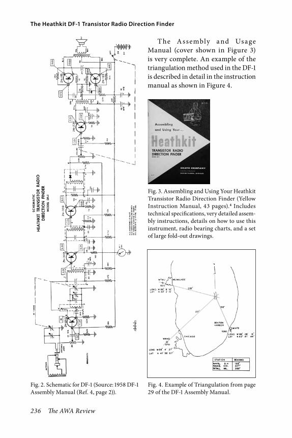
236 The AWA Review
The Heathkit DF-1 Transistor Radio Direction Finder
Fig. 2. Schematic for DF-1 (Source: 1958 DF-1 Assembly Manual (Ref. 4, page 2)).
T he Assembly a nd Usage Manual (cover shown in Figure 3) is very complete. An example of the triangulation method used in the DF-1 is described in detail in the instruction manual as shown in Figure 4.
Fig. 3. Assembling and Using Your Heathkit Transistor Radio Direction Finder (Yellow Instruction Manual, 43 pages).4 Includes technical specifications, very detailed assem-bly instructions, details on how to use this instrument, radio bearing charts, and a set of large fold-out drawings.
Fig. 4. Example of Triangulation from page 29 of the DF-1 Assembly Manual.

Volume 28, 2015 237
Brueschke
Restoration of the DF-1The DF-1 Heathkit Direction Finder is seen occasionally on eBay or at radio flea markets. Virtually all DF-1s need replacement of all electrolytic capaci-tors and repair of the antenna.
To restore the DF-1, remove the two screws holding the rear panel. Then loosen the upper set screw holding the antenna and pull up the antenna. Check the antenna for continuity as broken antenna wires are difficult if not impos-sible to repair. Next, repair cracked or chipped areas with clear 5-minute epoxy. The result of such a repair is shown in Figure 5. After one hour or longer, paint the entire antenna with black semi-gloss non-metallic paint.
Remove the obsolete old style 9-volt batteries if present (Fig. 6). The spare is on the right of Figure 6. Later, when
the chassis is out, replace the leads for the left battery with standard 9-volt transistor battery leads (see Figure 7). To remove the chassis, unsolder the speaker leads. Remove the wire connec-tion to the antenna socket. This will be replaced when the chassis is re-assem-bled. Remove the screws holding the
Fig. 5. Directional Antenna Restoration (see text).
Fig. 6. View of original battery and spare. These are no longer made. A standard 9-volt bat-tery is an effective replacement.

238 The AWA Review
The Heathkit DF-1 Transistor Radio Direction Finder
Fig. 7. Location of replacement 9-volt battery.
Fig. 8. Location of electrolytic capacitors prior to replacement.

Volume 28, 2015 239
Brueschke
top of the chassis. These are on the top of the case on the right side. Carefully remove the front panel and chassis. You can now install the new battery con-nection (Fig. 7) after removing the old connections.
Remove and replace all the elec-trolytic capacitors (Fig. 8). Replace the sensitivity control if necessary. These items and their values are shown in Figure 9. Test and re-assemble.
The Heathkit DF-2 Transistor Tor Radio Direction FinderThe DF-2 is shown in Figure 10 (Jay Whipple, Jr. collection), and the sche-matic is shown in 1959 (Ref. 5, page 57) and in the Heathkit Fall and Winter Catalog 1960–1961 (Ref. 6, page 51).
It was priced at $69.95. The DF-2 had six transistors and used six standard batteries. It used the same transistors as the DF-1. It had two bands—Bea-con (aeronautical and marine: 200 to 400 kilocycles) and Broadcast. It has a number of features that are like those of the DF-1 but it differs by having two bands, a larger speaker, a larger ferrite antenna, and push-button dual light illumination for the tuning dial. The DF-2 is rare and is seldom seen on eBay or at radio flea markets.
The DF-3 Three-Band Transistor Direction Finder KitThe DF-3 was advertised as a deluxe 3-Band Mariner direction finder (Ref. 6, pg. 51). It was priced at $99.95
Fig. 9. View of parts after removal. Original battery cables are shown and the 5k sensitivity control, which sometimes needs replacement.

240 The AWA Review
The Heathkit DF-1 Transistor Radio Direction Finder
in kit form and at $169.95 for the factory wired option. A copy of the DF-3 from the 1960–1961 Heathkit Fall and Winter Catalog shows the DF-3 (Ref. 6, pg. 51). The appearance of the DF-3 (Fig. 11) is markedly different from the DF-2 (Fig. 10). The DF-3 uses nine transistors all different from those in the DF-2. It was powered by 6 size “D” flashlight batteries with a battery life of 500–1000 hours. The DF-3 has three bands—Bea-con band 200 to 470 kHz, Broadcast
Fig. 11. DF-3 copied from Heathkit 1960-61 Catalog. $99.95 was the kit price. The DFW-3 Wired price was $169.95.
Fig. 10. Heathkit DF-2 (Jay Whipple, Jr., collection).

Volume 28, 2015 241
Brueschke
band 550 to 1600 kHz, and Marine band 1700 to 3400 kHz. It came with a pre-aligned tuning section, as well as a sense antenna. The tuning unit features a separate RF amplifier, a mixer, and an oscillator stage, as well as a larger com-pass rose, a re-designed ferrite antenna, and a 4” × 6” waterproof speaker. This was replaced in the fall of 1961 by the MR-11, which was priced at $109.95 (Ref. 7, pg. 25) and was advertised as an improvement over the DF-3. The DF-3 is very rare.
ConclusionThis ends the description of the DF-1, DF-2, and DF-3. While these three direction finders were sold for only a couple of years, they were a marvel of technology at the time, in kit form, for direction and position finding applications.
References1. Heathkits for 1957 and the 1957 Heathkit
Spring Flyer [Both did not list the DF-1].2. Radio and Television News (1958, May,
p 85). [DF-1 Heathkit Transistor Radio Direction Finder Kit $54.95. This may be the first ad for the DF-1].
3. Heathkits for 1958. [Shows DF-1 on page 55, priced at $54.95. This is the first Heathkit Catalog to show the DF-1].
4. Assembling and Using Your Heathkit Transistor Radio Direction Finder Model DF-1, Complete with Large Fold-Out Insert, 1958. The Heath Company, Benton Harbor, Michigan. (Author’s collection.)
5. Heathkits Two Band Direction Finder Kit, DF-2. Heathkits for 1959. [page 57:
DF-2 $69.95. Shows DF-1 on same page, $54.95].
6. Heathkit Fall and Winter 1960–1961 Catalog. [$69.95 DF-2, page 51; $99.95 DF-3, page 51, $169.95 Model DFW-3, page 51]. (Author’s collection.)
7. Heathkit Catalog Fall and Winter 1961-1962. [No DF-1, DF-2 or DF-3 are shown. MR-11 $109.95 is shown and is somewhat similar to the DF-3].
AcknowledgementsI want to thank Tina Brueschke Mack for assembling the manuscript, Patri-cia Brueschke for editorial assistance, Susan E. Golebiowski for her photog-raphy expertise and assistance, and my wife, Frances, for her endless patience and support of my collecting interests. With special thanks to Jay Whipple, Jr., for the loan of his Heathkit DF-2, and Michael Mack. Without the help and encouragement of these individuals this article would not have been completed.
Photo CreditsAll items shown in the Figures are in the collection of the author with the exception of the DF-2, which is part of the Jay Whipple, Jr., collection. All photographs are attributable to Susan E. Golebiowski.
About the AuthorErich E. Brueschke, BSEE, M.D., FAAFP, KC9ACE is a current holder of the Extra Class amateur radio license. He held the call sign WΦBPS in high school in 1948. He was born on a ranch in South Dakota. After graduating from the South Dakota School of Mines and

242 The AWA Review
The Heathkit DF-1 Transistor Radio Direction Finder
Technology with a B.S. in Electrical Engineering, he went on to work for the Hughes Research and Development Laboratories in Culver City, Califor-nia, for five years. There he specialized in magnetics and the effects of high vacuum on components. His last work there focused on the Surveyor space-craft in 1961–1962, which landed on the moon in 1966. He left Hughes to attend medical school at Temple University School of Medicine in Philadelphia, Pennsylvania. After completing his medical training, he became a Cap-tain in the United States Air Force at the Aerospace Medical Research Laboratories at Wright-Patterson Air Force Base in Dayton, Ohio for two years. Subsequently he practiced family medicine in California and then joined the Illinois Institute of Technology Research Institute in Chicago, Illinois, where, as Director of Medical Engineer-ing Research, he worked on artificial internal organs, including powering the artificial heart, for seven years. He then joined Rush Medical College in Chi-cago, where he was Chairman of Family
Medicine, and Professor of Physiology and Molecular Biophysics. He was also Program Director for the Rush-Christ Family Practice Residency Program for 17 years. He subsequently became Dean of Rush Medical College for six years. He retired as Dean in 2000. He is currently the Distinguished Professor of Medicine at Rush Medical College at Rush University in Chicago. He has two patents issued and has published numerous papers in engineering, medi-cal and scientific literature, and is a member of a number of professional societies. He has previously published in the AWA Review in 2010, 2012, 2013, and 2014. His major collecting and res-toration interests are early scientific educational apparatus, crystal sets, early battery radios, and Heathkits. He has collected, preserved, and restored radios and scientific devices for over 31 years. He has been a member of the AWA for 25 years and is a member of the Radio Club of America. He is cur-rently Associate Editor of The AWA Review. He invites correspondence and comments at [email protected].
Erich Brueschke with several of his DF-1s.

Volume 28, 2015 243
WHA Madison—Is it Really the Nation’s Oldest Station?
©2015 Dan Clark
Abstract“The Oldest Station in the Nation—WHA Madison” That is the way the station iden-tification of WHA was announced in the 1950s. But is it really the oldest? KDKA in Pittsburgh is usually considered the oldest broadcast station in continuous operation.
Assistant Director of WHA Harold Engel was very proud of the heritage of this remarkable pioneer station. He felt that since 9XM, the experimental forerunner of the station was active during World War 1 when most others were silenced, the title was deserved. Even Harold B. McCarty, the Director of the station since 1931, did not agree with Engel, but permitted the announcement to be made at every station break.
It is a fascinating story, both from the technical viewpoint, as well as the politi-cal and programming viewpoint. I believe that readers of this publication would be most interested in the technical side of it, so that will be the approach in this article. Those interested in both, will find it in great detail in a book published in 2006.1 Much of the earliest history in this article was provided by this book, which is highly recommended.
It all began in 1914, when University of Wisconsin Professor Edward Ben-nett of the Electrical Engineering Department built an amateur spark transmitter, and applied for a license from the Department Of Commerce. An experimental license with the call sign 9XM was granted. The 9 identified the Midwest 9th call area (which was much larger then than it is now), the X stood for Experimental, and the M stood for Madison. Another professor, Earle M. Terry of the University of Wis-consin Physics Department, asked to
use the license for some radiotelegraph equipment that he and some of his stu-dents were building. Bennett gave the license to Terry, who then transferred the license to the university in June of 1915.2
The original station equipment was built by Professor Terry, aided by students Malcolm Hanson and Carl Kottler, using lab equipment and whatever they could scrounge. It was located in the basement of Science Hall on the university campus, using a wire antenna that ran from a neighboring

244 The AWA Review
WHA Madison—Is it Really the Nation’s Oldest Station?
chimney to the peak of the Science Building. The transmitter was placed in operation in 1915.
Figure 1 shows the spark transmitter as it appeared in 1916. As can be seen, it employed a rotary spark gap, and transmitted power of 4 to 5 kW. The Leyden jars on the top shelf were used to provide capacitance for tuning. These were originally filled with water, but would occasionally arc over and crack the glass jar, drenching the equipment and the operator. Filling them with oil solved that problem.3
The receiving equipment, consisting of loose couplers and crystal detectors, are shown on the lower level in front of the operator. Time signals could be received from station NAA in Virginia operating on 2500 meters (120 kHz).
The transmitter operated on 475 or 750 meters (631 kHz and 400 kHz) depending on the time of day, normally evening and overnight. Later in 1916 the transmitter was modified to operate on 1700 meters (176 kHz). The station was operated by a half-dozen physics and engineering students known around the campus as the “wireless squad.” The transmitter was said to produce a tremendous sound and produced bright blue flashes, which could be seen coming from the basement windows at night. When asked about the range of the station, the student operators would jokingly reply “10 miles with the windows closed, and 15 miles with windows open”.4
The station would at first be used for point to point communications, there were other experimental stations, many
of them from other universities, doing similar work. Operators would ask for signals reports from their contacts, and also ask for reports from anyone else listening in. The large number of responses, many from amateur opera-tors, indicated that there was an audi-ence for the transmissions.
Professor Terry wanted to use the transmitter on a regular schedule to provide something that would be use-ful to the general public. It was decided that a weather forecast would be easy to obtain, and would certainly be of interest to farmers. Navy stations were transmitting weather forecasts for the Great Lakes, and in 1914 the Univer-sity of North Dakota station had begun wireless telegraphic weather reports. In Madison, the local U.S. Weather Bureau meteorologist was a wireless fan, and wrote to the Bureau in Washington that 9XM could be used to broadcast weather information. Permission was granted, and on December 1st, 1916, an announcement in the Madison Wiscon-sin State Journal stated that weather broadcasts would begin over 9XM. The first one was made December 4th, 1916 and continued daily, except Sunday, at 11 a.m. This was the first regular broadcast of the station that later would become WHA.5
Word was spreading among the public that things were happening on wireless. More people were becoming interested, and building crystal sets to receive the broadcast. Like many other pioneer stations, 9XM would send out information on request on how to construct a crystal set. Student

Volume 28, 2015 245
Clark
operator Malcolm Hanson produced a simple design that was easy to build and furnished free crystals and wires to anyone who asked. To further aid
listeners, he also provided slow speed Morse transmissions on schedule to assist farmers and others learning Morse code.6
Fig. 1. Spark transmitter as it appeared in 1969.

246 The AWA Review
WHA Madison—Is it Really the Nation’s Oldest Station?
Another broadcast item that started in February of 1917, was the telegraphic broadcast of a basketball game between Wisconsin and Ohio. It is not known if the play-by-play information was sent to the station by telephone, or by stu-dent runners from the nearby gym. The broadcast was heard by Buckeye fans in Ohio who heard their team lose to Wisconsin.7
The Change to Telephonic TransmissionsProfessor Terry grasped the limitations of spark transmitters early in 1915, and conducted experiments with 3-element vacuum tubes. The first experimen-tal telephonic transmissions, as they were called, occurred early in 1917. Pro-fessor Terry invited some university officials to witness the new medium, but unfortunately it was less than a success. It was reported that the voice was unintelligible, and the phonograph music severely distorted.7 The method of modulation is unknown, but the first attempts by some experimental stations simply connected the modulator tube(s) in series with the plus or minus power feed to the RF tube(s). Grid modulation might have been tried, but is known to be rather difficult to adjust. Or if it was a low power station, it might be modu-lated by placing a carbon microphone in series with the antenna circuit. Sta-tion 9XM experiments used a tube-type modulator.
Professor Terry was the adviser to a young graduate student by the name of Raymond A. Heising. He graduated from the University of Wisconsin with
a Masters degree in 1914, and accepted a position with the Western Electric company. He may have developed an interest in radio from Professor Terry, but would be unlikely to have any connection with 9XM since he left the university before the station was built. While at Western Electric, he patented a modulation system essentially placing a modulator tube in series with the power feed of an RF tube. But during the First World War, to solve a problem with air-to-ground radio communication, he devised another modulation scheme. This involved placing an audio choke in the common high voltage supply line to both the RF and modulator tube(s). So when the modulator tube drew vary-ing audio current, it would raise and lower the high voltage available to the RF stage in accordance with the audio waveform. 9XM and WHA undoubt-edly made use of this system. The sys-tem bears Heising’s name,8 and was used to modulate almost all broadcast transmitters during the 1920s and into the early 1930s. It was then displaced by the more familiar Class B modulators using a transformer. For an interesting sidelight how that came to be, check out a website for Loy Barton, Forgotten Pioneer of Radio.9
The War YearsThe First World War, which began in Europe in 1914, finally impacted this country in April of 1917. The Depart-ment of Commerce ordered all wireless operation to be shut down nation-wide. It also ordered all aerial wires and radio apparatus, both sending and receiving,
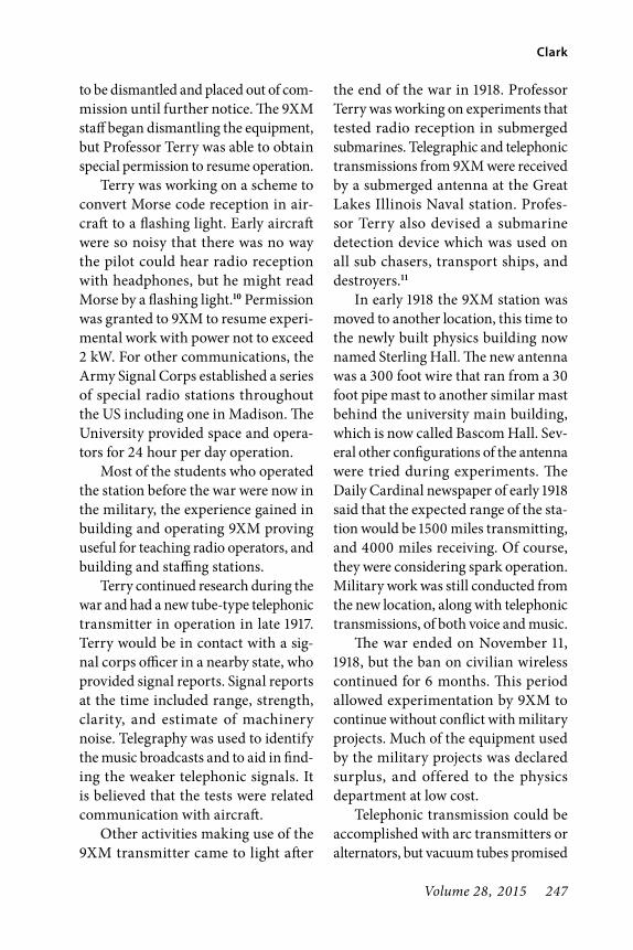
Volume 28, 2015 247
Clark
to be dismantled and placed out of com-mission until further notice. The 9XM staff began dismantling the equipment, but Professor Terry was able to obtain special permission to resume operation.
Terry was working on a scheme to convert Morse code reception in air-craft to a flashing light. Early aircraft were so noisy that there was no way the pilot could hear radio reception with headphones, but he might read Morse by a flashing light.10 Permission was granted to 9XM to resume experi-mental work with power not to exceed 2 kW. For other communications, the Army Signal Corps established a series of special radio stations throughout the US including one in Madison. The University provided space and opera-tors for 24 hour per day operation.
Most of the students who operated the station before the war were now in the military, the experience gained in building and operating 9XM proving useful for teaching radio operators, and building and staffing stations.
Terry continued research during the war and had a new tube-type telephonic transmitter in operation in late 1917. Terry would be in contact with a sig-nal corps officer in a nearby state, who provided signal reports. Signal reports at the time included range, strength, clarity, and estimate of machinery noise. Telegraphy was used to identify the music broadcasts and to aid in find-ing the weaker telephonic signals. It is believed that the tests were related communication with aircraft.
Other activities making use of the 9XM transmitter came to light after
the end of the war in 1918. Professor Terry was working on experiments that tested radio reception in submerged submarines. Telegraphic and telephonic transmissions from 9XM were received by a submerged antenna at the Great Lakes Illinois Naval station. Profes-sor Terry also devised a submarine detection device which was used on all sub chasers, transport ships, and destroyers.11
In early 1918 the 9XM station was moved to another location, this time to the newly built physics building now named Sterling Hall. The new antenna was a 300 foot wire that ran from a 30 foot pipe mast to another similar mast behind the university main building, which is now called Bascom Hall. Sev-eral other configurations of the antenna were tried during experiments. The Daily Cardinal newspaper of early 1918 said that the expected range of the sta-tion would be 1500 miles transmitting, and 4000 miles receiving. Of course, they were considering spark operation. Military work was still conducted from the new location, along with telephonic transmissions, of both voice and music.
The war ended on November 11, 1918, but the ban on civilian wireless continued for 6 months. This period allowed experimentation by 9XM to continue without conflict with military projects. Much of the equipment used by the military projects was declared surplus, and offered to the physics department at low cost.
Telephonic transmission could be accomplished with arc transmitters or alternators, but vacuum tubes promised

248 The AWA Review
WHA Madison—Is it Really the Nation’s Oldest Station?
to be a better approach. But in 1917 there were none that were commer-cially available. Even if there were, 9XM would certainly be unable to afford them. So it was decided by Professor Terry to fabricate transmitting tubes for the station in-house.
A student of Professor Terry named Cyril M. Jansky Jr. was one of the constructors of the transmitting tubes. Years later, on November 24th of 1958 Jansky gave a presentation at the WHA Family Dinner that described the process. Here is an excerpt from that presentation.
Learning to building vacuum tubes meant learning to be a glass blower. If there ever was a tech-nique to try the patience of Job, it is glass blowing. Many were the tubes that I carried through the various stages of construction and in some instances through the process of pumping out the air only to have a crack develop somewhere. Thus several weeks of work would end and I would have nothing to show for it except expe-rience. Then I would start over.
At the start of this program Professor Terry was a far better glass blower than I. Therefore, if the main objective of this project had been to produce three element power tubes as soon as possible, I have no doubt he could have accomplished this result faster by himself. However, the prime func-tion of both undergraduate and post graduate student research in
science is, or at least should be, the education of the student. Profes-sor Terry was first and foremost a teacher. Therefore, in the early stages of my vacuum tube project he devoted his efforts to so guiding my work that I would secure the greatest benefit. His method was the same with all of his students. A critic of scientific education said we spend too much time trying to fill students’ heads with informa-tion and not enough time teach-ing them how to use their heads. Professor Terry was not that kind of a teacher. From him we learned method. Through him we came to have a better understanding of the psychology of the approach to scientific research and we grew to love the science he taught.
As time progressed and I gained greater competence as a glass blower, I found Professor Terry working by my side, he specializing in certain phases of the construction work and I in others. Then we really began to get results. After the tube has been constructed it had to be exhausted, that is, the air pumped out. During this process the tube was baked in an electric furnace and all occluded gas driven out of the metal parts by bringing them to red heat by electronic bombard-ment. This was a long and ticklish process. Mr. Foerst, our physics department machinist, assisted us by making the collapsible man-drels used in making grids and

Volume 28, 2015 249
Clark
at times with other mechanical details. Professor Roebuck of the physics department provided us with the liquid air necessary in the exhausting process. The first tubes with which we were success-ful took many hours to exhaust. At first it was I who manned the pumps, I have a vivid memory of the hours of labor which went into both the construction and exhausting of every one of the first five tubes now on display in the case in the entrance to Radio Hall. These five, plus one which I have in my possession, were the tubes for the first radio telephonic transmissions.
Figure 2 shows C. M. Jansky Jr. at the 1958 WHA Family Dinner holding one of the tubes he made circa 1919. Note: the tubes Jansky refers to are no longer in Radio Hall, but one of them is on display currently at the headquarters of Wisconsin Public Radio in Madison.
Figure 3 is a view of the Jansky tube in a glass display case. The stripes on
the glass envelope of the tube are prob-ably ions or particles from the filament after passing through the grid.
Figure 4 shows a view of the tube exhaust setup. At the left is student and chief operator Malcolm Hanson, and at the right is Professor Earle Terry. I can identify a roughing pump at the left, and I believe one in the center might be a mercury diffusion pump. A close look at the tube at the right shows the
Fig. 2. C. M. Lansky Jr. at the 1958 WHA Family Dinner holding one of the tubes he made circa 1919.
Fig. 3. A view of the Jansky tube in a glass display case.
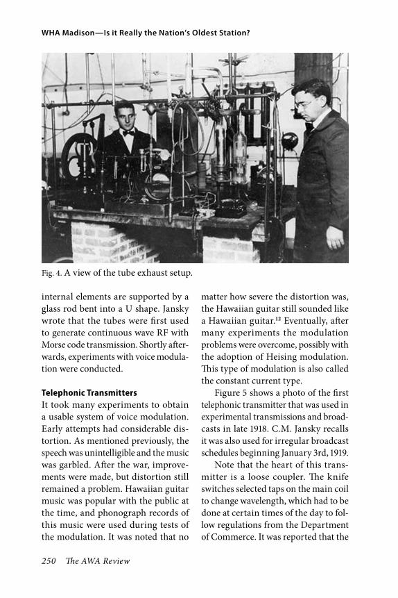
250 The AWA Review
WHA Madison—Is it Really the Nation’s Oldest Station?
internal elements are supported by a glass rod bent into a U shape. Jansky wrote that the tubes were first used to generate continuous wave RF with Morse code transmission. Shortly after-wards, experiments with voice modula-tion were conducted.
Telephonic TransmittersIt took many experiments to obtain a usable system of voice modulation. Early attempts had considerable dis-tortion. As mentioned previously, the speech was unintelligible and the music was garbled. After the war, improve-ments were made, but distortion still remained a problem. Hawaiian guitar music was popular with the public at the time, and phonograph records of this music were used during tests of the modulation. It was noted that no
matter how severe the distortion was, the Hawaiian guitar still sounded like a Hawaiian guitar.12 Eventually, after many experiments the modulation problems were overcome, possibly with the adoption of Heising modulation. This type of modulation is also called the constant current type.
Figure 5 shows a photo of the first telephonic transmitter that was used in experimental transmissions and broad-casts in late 1918. C.M. Jansky recalls it was also used for irregular broadcast schedules beginning January 3rd, 1919.
Note that the heart of this trans-mitter is a loose coupler. The knife switches selected taps on the main coil to change wavelength, which had to be done at certain times of the day to fol-low regulations from the Department of Commerce. It was reported that the
Fig. 4. A view of the tube exhaust setup.

Volume 28, 2015 251
Clark
changes sometimes had to be done in the middle of a broadcast. At this point in time 9XM used 1000 meters (300 kHz) for code, and 1300 Meters (231 kHz) for voice.
I wondered if the movable part of the coupler was to couple the trans-mitter to the antenna, or to provide adjustable positive feedback to control the oscillation of the RF tube. I believe it is the latter, since the antenna leads appear to lead to the large coil. So the transmitter is essentially a power RF oscillator, sometimes referred to as a self-excited type. Most broadcast transmitters were of this type up to the middle of the 1920s.
The microphone is a single button carbon type as found in the telephones at the time. The twisted pair leads to a small box, which may be a transformer to drive the modulator tube seen at the
left. Part of the battery bank would probably supply button current for the carbon microphone. The two sets of batteries at the extreme left and right would provide the filament voltage for the tubes. Judging from the number of cells it may have been fairly high. Plate voltage for the tubes was furnished by a motor-generator set from the phys-ics department. There appears to be a telegraph key at the extreme lower right for sending CW Morse.
The tubes are mounted in wooden cradles and do not have sockets. Con-nections were made directly to the leads coming out of the bottom pinch of the tubes. Later versions had differ-ent shaped envelopes, and appeared to have plugs.
Tests of the modulation on this and later transmitters was often done by phonograph records. It was usual for
Fig. 5. The first telephonic transmitter that was used in experimental transmissions and broadcasts in late 1918.

252 The AWA Review
WHA Madison—Is it Really the Nation’s Oldest Station?
many pioneering stations as well as 9XM to simply place the microphone in front of the phonograph horn. Local music stores were generous in supplying records, since they found it increased sales. Professor Terry tried to design an electrical phonograph pickup, but was not satisfied with the result.13
In June of 1920, a new and higher power transmitter was planned. 9XM continued broadcasting telegraphic weather reports until the new transmit-ter went on the air. Regular programs of recorded music were broadcast over the new transmitter in November 7th, 1920, 5 days after the historic broadcast of the election results by KDKA. 9XM also broadcast the election results on November 2nd, but by wireless teleg-raphy. It is not known if these were locally gathered, or received via relay from KDKA. With the start of 1921, a new experimental license was issued specifying that 475 meters (631 kHz) would be used for code, and 800 meter (375 kHz) for voice. Voice broadcasts would now be made on a regular sched-ule. So the delay in adopting a regular schedule in programming by 9XM is why KDKA is now considered the oldest station in continuous operation. 9XM/WHA may be the second oldest. Also, it can be the oldest educational station in the nation, but that honor would have to be shared with WLB at the University of Minnesota (now KUOM) which was licensed the same date as WHA.
Figure 6 is an overall view of the new 1920 transmitter. The heart of the transmitter again was a loose coupler,
but the new one was of much greater size than the previous. The two left tubes are the RF tubes operated in par-allel; the two right hand tubes are the modulator, also in parallel. The smaller tube at the extreme right is probably the modulator driver. Operator Malcolm Hanson had a close call by accidentally coming in contact with the high voltage feed in the transmitter and said it was 2000 volts. The large coils at the left are part of the spark transmitter.
Figure 7 is a closer view of the trans-mitter and loose coupler. A line going out the window, presumably to the antenna, is wrapped around the large coil of the coupler. The tube at the left appears to have a socket or an insulated support at the bottom. The modulator driver at the right and above the group of four is now a full size tube rather than the smaller size of earlier versions of the transmitter.
Figure 8 which is dated 1922, is an overall view of the transmitter room. The loose coupler is gone, and has been replaced by two vertical spider web coils. They are barely visible at either side of the left hand tube pair. The vertical panel at the right is the oper-ating position which; contains some receiving loose couplers, the telephone microphone, and a telegraph key. This served as the studio at the time. All announcements were made from this panel, and some professors would give lectures into the telephone microphone.
In Figure 9, the spider web coils are more visible. There appears to be a pair of them at the left end with a wire from one of them leading up to

Volume 28, 2015 253
Clark
Fig. 6. An overall view of the new 1920 transmitter
Fig. 7. A closer view of the transmitter and loose coupler.

254 The AWA Review
WHA Madison—Is it Really the Nation’s Oldest Station?
Fig. 8. An overall view of the transmitter room.
Fig. 9. The spider web coils are more visible.
some capacitors above the meters. This appears to be the method of coupling to the antenna. The person at the left of the photo is Malcolm Hanson, who
was a builder of tubes; of transmitters, the chief operator, announcer, program scheduler and publicity man, really the spark plug of the operation.

Volume 28, 2015 255
Clark
Also in Figure 9, the tubes now have spherical envelopes rather than the original tubular ones. They look very much like commercially made tubes with sockets. This is may be the work of the physics department Glass Lab, which had a professional glass blower. It is known that they were still using the handmade tubes in late 1923, since it was reported that the station was off the air having exhausted their supply of handmade tubes. New tubes could not be made for a few weeks since the phys-ics department glassblower had injured his hand in an accident. Professor Terry was busy with teaching duties, and could not participate in tube making. Malcolm Hanson had other problems. It might be assumed that after the glass blower resumed work, additional tubes were made and used for some time after 1923, but it is unknown for how long.15
The Birth of WHA9XM continued in operation through 1921, with regular programming and even spark and CW Morse transmis-sion after 10 PM. However in December of 1921, the Chicago Radio Inspector informed Professor Terry that 9XM was not authorized to use broadcasting on its 800 meter wavelength. To con-tinue, it would be necessary to switch to other frequencies, and apply for a commercial license. They were allowed to broadcast after changing frequency until the new license was granted. A provisional license was granted, and had the call letters WHA on it. The call letters apparently were randomly selected by the Bureau of Commerce.
Malcolm Hanson traveled to Chicago and took the test for a new Commercial First Class Radio License. His license carried the date of December 23rd, 1921, the same as the new license for WHA. The new license took effect on January 13th, 1922. The 9XM call was still used for experiments using both code and telephonic transmissions until 1926, but the spark transmitter was not used after 1923. After 1926 the call used was 9DW, later W9DW, and finally W9YT. That last is the present call sign of the University of Wisconsin Amateur Radio station.
A new transmitter was required for the assigned frequencies, which could be 485 meters (618 kHz), or for a special occasion 60 meters (833 kHz). This is probably the transmitter shown in Figure 8 and 9. Power was reported to be 400 to 500 watts. A new antenna described as being a T type using a four wire cage supported by a large wooden frame, was mounted on top of Sterling Hall. A photo, which is not of good enough quality to publish, shows it to be a horizontal cage strung between two vertical 25 ft. high wooden A frame supports. If it really was a T antenna, it was probably center fed and the feed line must have been doing most of the radiating.
Studio FacilitiesFor some time, the transmitter room was the studio for on-the-air perform-ers. It was crowded and reported to be very noisy. Later, Malcolm Han-son devised a broadcast booth about 5 ft. square with the walls lined with
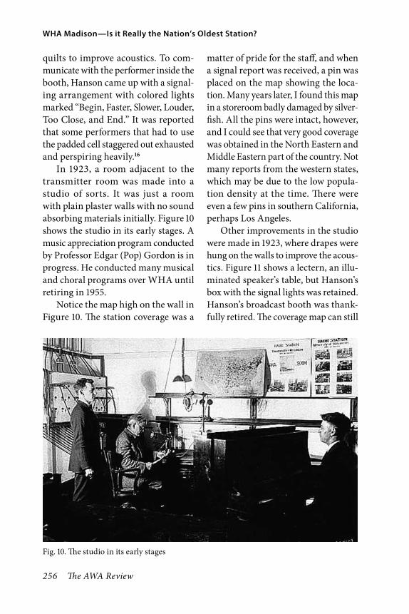
256 The AWA Review
WHA Madison—Is it Really the Nation’s Oldest Station?
quilts to improve acoustics. To com-municate with the performer inside the booth, Hanson came up with a signal-ing arrangement with colored lights marked “Begin, Faster, Slower, Louder, Too Close, and End.” It was reported that some performers that had to use the padded cell staggered out exhausted and perspiring heavily.16
In 1923, a room adjacent to the transmitter room was made into a studio of sorts. It was just a room with plain plaster walls with no sound absorbing materials initially. Figure 10 shows the studio in its early stages. A music appreciation program conducted by Professor Edgar (Pop) Gordon is in progress. He conducted many musical and choral programs over WHA until retiring in 1955.
Notice the map high on the wall in Figure 10. The station coverage was a
matter of pride for the staff, and when a signal report was received, a pin was placed on the map showing the loca-tion. Many years later, I found this map in a storeroom badly damaged by silver-fish. All the pins were intact, however, and I could see that very good coverage was obtained in the North Eastern and Middle Eastern part of the country. Not many reports from the western states, which may be due to the low popula-tion density at the time. There were even a few pins in southern California, perhaps Los Angeles.
Other improvements in the studio were made in 1923, where drapes were hung on the walls to improve the acous-tics. Figure 11 shows a lectern, an illu-minated speaker’s table, but Hanson’s box with the signal lights was retained. Hanson’s broadcast booth was thank-fully retired. The coverage map can still
Fig. 10. The studio in its early stages

Volume 28, 2015 257
Clark
be seen on the wall in the new studio. At the left is seated Professor Earle Terry, and at the lectern is Professor W. H. Lighty, WHA’s first program director who established WHA as an educational station. A new compact microphone was purchased, the type is unknown. Microphones were one of the few things that were purchased, apparently it was difficult to build a good one.
In 1925, a new studio in a room upstairs from the transmitter was opened. This was 16 by 19 feet, sound-proofed by “balsam wool” (sic), win-dow space was draped, and the floor effectively covered. A Steinway piano was good enough to allow musical pro-grams from this studio.
Loss of Malcolm HansonAs mentioned previously, Hanson was the most energetic and capable member of the 9XM and WHA stations, doing everything from building transmitters to scheduling and announcing. Unfor-tunately, he was not as energetic in keeping up with his engineering stud-ies. He was spending so much time at WHA that his grades suffered. Placed on probation for a time, the blow finally came in 1923 when he was “asked to leave” the university. He had been in the Navy during the war, so he rejoined the Navy after leaving WHA. As an interesting sidelight, another engi-neering student was “asked to leave” the University a couple of years before Hanson. Like Hanson, he went on to
Fig. 11. The studio with drapes, a lectern, and illuminated speaker’s table.

258 The AWA Review
WHA Madison—Is it Really the Nation’s Oldest Station?
better things afterward. His name was Charles A. Lindberg.17
Remote BroadcastsEarly 1923 marked the beginning of broadcasts from outside of the Sterling Hall transmitter and studio location. Basketball games might be broadcast from the gym, musical concerts from Music Hall (a former church), also from the University Stock Pavilion. That last may sound like an unlikely place for a musical concert, but it had the best acoustics, and many famous artists per-formed there over the years. Some lec-tures were broadcast from classrooms in various university buildings.
All this was accomplished by wire lines strung through underground tunnels that ran to all buildings in the University campus. These were to carry steam for heating, electricity, water, and telephone lines. I have helped string audio lines through these tunnels in the 1950s, and can advise that they were always at 90 degrees temperature or more in any season of the year due to the steam lines. One could see the rout-ing of tunnels as their heat melted a light snowfall on the campus lawns. The audio lines varied from very neat lead sheathed cables in the best telephone practice to twisted pair lines draped over plumbing. Many of the later lines were rugged twisted pair lines type WI-110B surplus from WWII. The older lines might have been surplus twisted pair from WWI.
The engineer handling the remote broadcast would haul a suitcase con-taining an amplifier, headphones, a
microphone, and a number of batter-ies to the site. Connecting the ampli-fier to the line back to the studio, the program would be broadcast live.18 The first broadcast of a basketball game was not a success. Listeners complained that they could not hear the announcer over the roar of the crowd. This was long before the use of broadcast booths.
I was fortunate to have an oppor-tunity to examine one of the remote amplifiers from the early days. I found a black suitcase in a storeroom, opened it, and found an old amplifier with two early vintage tubes on the front panel. These were Western Electric VT-2 vac-uum tubes, with plates that really were plates, and grids that were really grids. Also in the suitcase was a classic double button carbon microphone suspended by springs inside a circular hoop. I car-ried it all to the service shop, established that the tube filaments were good, and decided to see if it still worked. Con-necting suitable power supplies to the battery leads, the microphone button current was adjusted to the 50 ma. value specified in a typewritten tag on the panel. My boss was now interested in the proceedings, and we were rewarded by our voices booming out of a bass reflex speaker above the bench. We were surprised with the good quality audio, somewhat heavy on the low frequency end, but the highs were still there. I believe it would be broadcast quality even for modern AM stations. A couple of announcers passing by tried out the microphone and asked if we could put it in the announcers booth, since it made their voices sound so good.
Volume 28, 2015 259
Clark
Problems with Frequency AssignmentsIn the middle 1920s the available broadcast frequencies were becom-ing extremely crowded. WHA had to time-share the 535.4 meter (560 kHz) frequency with KYW in Chicago, which curtailed the broadcasting time for WHA. In 1927, Professor Terry peti-tioned the newly formed Federal Radio Commission for a new frequency he had chosen, but was turned down, for that one and six others he requested. There followed a seemingly endless changing of frequencies, and fights with other sta-tions for time sharing arrangements. It all came to a head in 1928, when a Chi-cago station disregarded its agreement with WHA causing serious interfer-ence that severely cut the station’s range. Another station did the same thing. A complaint was lodged with the Federal Radio Commission which brushed it off saying it was a private agreement between the stations.19 The situation was so discouraging that consideration was given to abandoning WHA. The Com-mission finally allowed WHA to use 940 kHz and if there was no interfer-ence, they could use it during daytime hours. From 1929 to the present, WHA has been a daytime-only station but has now received permission to broadcast after sunset at a power of 51 watts.
Technical ImprovementsIn 1926, the transmitter was rebuilt, and the power increased from 625 watts to 750 watts. Presumably they were now using commercially made transmitter tubes rather than the handmade ones.
Included in the rebuild was a “crystal control frequency stabilizer.” A pub-lished report20 stated that the stabi-lizer was supposed to reduce fading in reception. I wonder how it did that. Crystal control spread rapidly among broadcasters after that. In some corre-spondence dating to the early thirties I saw an advertisement for a large num-ber of used self-excited transmitters offered for sale.
The first station to use crystals for frequency control was reported to be WEAF in New York City in 1926.21 Crystal technology was known in the early 1920s, but was not widely used initially. An article in QST 22 described how amateur radio operators could cut and grind quartz to produce radio crystals, but most amateur transmit-ters were self-excited types until the middle 1930s.
A New DirectorSad news, Professor Terry, who began and guided the station through the early years died of a heart attack in the spring of 1929. Professor Edward Bennett, of the Electrical Engineering Department, replaced Terry as the WHA Manager. It was Bennett that loaned his radio license for 9XM to Terry for his Physics Department wireless operation 14 years earlier. Regrettably, much information about the early years of the station was lost, because Terry’s widow discarded all his files.
In the spring of 1929, a graduate student in theater named Harold B. McCarty (Mac to his friends) was asked to take over as an announcer for a one

260 The AWA Review
WHA Madison—Is it Really the Nation’s Oldest Station?
hour program. He was hired as an announcer in October of 1929 at a sal-ary of $25 a month. He later became chief announcer, later program man-ager, and in 1931, manager.
Figure 12 shows McCarty at the microphone in 1931. He said the tele-phone had to be taken off hook to pre-vent incoming calls from disrupting announcements. McCarty served the
station for more than 35 years until retiring in 1966. Under his direction the single AM station later grew to include WHA-FM, further expanding into an innovative state-wide FM network, multiple programming with microwave channels, stereo broadcasting, and the establishment of WHA-TV. Also on his watch, a statewide educational televi-sion network was begun.
Fig. 12. McCarty at the microphone in 1931.
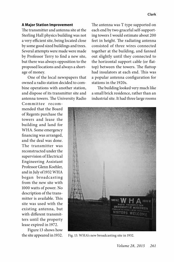
Volume 28, 2015 261
Clark
A Major Station ImprovementThe transmitter and antenna site at the Sterling Hall physics building was not a very efficient site, being located close by some good sized buildings and trees. Several attempts were made were made by Professor Terry to find a new site, but there was always opposition to the proposed locations and always a short-age of money.
One of the local newspapers that owned a radio station decided to com-bine operations with another station, and dispose of its transmitter site and antenna towers. The University Radio Commit tee recom-mended that the Board of Regents purchase the towers and lease the building and land for WHA. Some emergency financing was arranged, and the deal was done. The transmitter was reconstructed under the supervision of Electrical Engineering Assistant Professor Glenn Koehler, and in July of 1932 WHA began broadcast ing from the new site with 1000 watts of power. No description of the trans-mitter is available. This site was used with the existing antenna, but with different transmit-ters until the property lease expired in 1972.
Figure 13 shows how the site appeared in 1932.
The antenna was T type supported on each end by two graceful self-support-ing towers I would estimate about 200 feet in height. The radiating antenna consisted of three wires connected together at the building, and fanned out slightly until they connected to the horizontal support cable (or flat-top) between the towers. The flattop had insulators at each end. This was a popular antenna configuration for stations in the 1920s.
The building looked very much like a small brick residence, rather than an industrial site. It had three large rooms
Fig. 13. WHA’s new broadcasting site in 1932.

262 The AWA Review
WHA Madison—Is it Really the Nation’s Oldest Station?
front to back; the first had the operators desk and monitoring equipment, the second the transmitter, and the third, machinery, transformers, and electrical equipment. I was unable to find any photos of the transmitters at this site.
The New StudiosThe one room studio in the Physics building (named Sterling Hall), was certainly inadequate by the early 1930s. A search for more suitable quarters was made, and one possibility was a vacant building that began as the university central heating plant in 1885. In 1933, funds from the New Deal Civic Works Administration, combined with funds from the University of Wisconsin were used to remodel the building to a first class radio studio site. The entire job cost about $18,232.
Figure 14 shows how Radio Hall appears today. By coincidence, it is adjacent to the site of the 9XM spark transmitter which was located in the room with the windows on the lower left of the photo. The old heating plant chimney on the right served as the
antenna support for one end of the 9XM antenna. Architect Frank Lloyd Wright once said that Radio Hall was one of the two most honest buildings in Madison. The other one was a downtown store. He would know, since he was a student at the University of Wisconsin when the building was new. He had no part in the heating plant design, but he did have a small contribution in the adjacent Science Hall construction. He wrote that the building architect allowed him to design some small metal fasteners for the roof trusses.23
The new facility had three studios, the largest was Studio A, which had a window facing the main lobby for spectators could watch a broadcast. The studio had excellent acoustics and occa-sionally had large orchestras and choral groups performing.
Figure 15 shows a pipe organ which was acquired from a local theater and assembled piece by piece by the first music director. The first organ recitals were broadcast from the new Studio A, even before remodeling of the building was complete. By December of 1934 the
Fig. 14. Radio Hall, 2015.

Volume 28, 2015 263
Clark
station remodeling was complete and the station staff moved in.
Studio B was a small announcer’s studio next to the main control room, and Studio C was a 12 by 12 foot stu-dio used for interviews and lectures. In the 1950s another studio was built in the basement for recordings next to a room equipped with several racks of tape recorders. Next to that was a room containing two FM transmitters, a main and a backup. A service shop was next to the transmitter room.
Figure 16 shows the main control room as it appeared in 1936. The control board was built by station engineers. The size of the room was about 10 feet square, and must have been very
crowded with all the equipment there. The amplifiers were later moved to the service shop directly below the control room. The remodeled building was known as Radio Hall until 1972, when the studios were moved to a newer and larger building at another site. Radio Hall was then renamed Old Radio Hall. During the period of operation as a radio studio, and later as an FM and TV transmitter site, it was a first class operation. H. B. McCarty would sometimes show visitors the front lobby and point out that the old heating plant boiler was located there. The only trace of the old heating plant was a little coal dust I found in a remote corner of the building.
Fig. 15. A pipe organ acquired from a local theater.
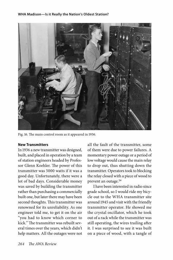
264 The AWA Review
WHA Madison—Is it Really the Nation’s Oldest Station?
New TransmittersIn 1936 a new transmitter was designed, built, and placed in operation by a team of station engineers headed by Profes-sor Glenn Koehler. The power of this transmitter was 5000 watts if it was a good day. Unfortunately, there were a lot of bad days. Considerable money was saved by building the transmitter rather than purchasing a commercially built one, but later there may have been second thoughts. This transmitter was renowned for its unreliability. As one engineer told me, to get it on the air “you had to know which corner to kick.” The transmitter was rebuilt sev-eral times over the years, which didn’t help matters. All the outages were not
all the fault of the transmitter, some of them were due to power failures. A momentary power outage or a period of low voltage would cause the main relay to drop out, thus shutting down the transmitter. Operators took to blocking the relay closed with a piece of wood to prevent an outage.24
I have been interested in radio since grade school, so I would ride my bicy-cle out to the WHA transmitter site around 1945 and visit with the friendly transmitter operator. He showed me the crystal oscillator, which he took out of a rack while the transmitter was still operating, the wires trailing after it. I was surprised to see it was built on a piece of wood, with a tangle of
Fig. 16. The main control room as it appeared in 1936.

Volume 28, 2015 265
Clark
wires around the crystal and the type 56 vacuum tube. Obviously it had been modified several times. He showed me one of the final amplifier tubes, a burned out one he was converting to a table lamp. I don’t know the number, but it was an external plate type.
The transmitter itself looked like any of the ones you can see in photos of 1930s vintage broadcast transmit-ters. It was housed in a large black case estimated to be 6 to 8 feet high and 9 feet wide, with doors in front with grated openings to allow viewing of the power tubes. Along the top was a series of meters of mismatched sizes and some indicator lights. A motor-generator set in the back room supplied the high voltage.
A New Station is AddedThe Wisconsin Department of Markets provided market information to newspapers and sometimes by rural telephone lines to growers and shippers of farm products. WHA was asked to broadcast the information on a schedule several times a day, but an agreement couldn’t be reached. So the Department of Markets management decided it would be advantageous to build their own station for the purpose. In December of 1922 a new station was built in Waupaca about 100 miles North of Madison. The call letters assigned to the new station were WPAH, which officially went on the air February 1923. Several changes in site were made until 1924 when a new site in the city of Stevens Point was established. The call sign was changed to WLBL in 1924.
This station had no connection with WHA at this time. It was licensed to the State of Wisconsin, while WHA was licensed to the University of Wisconsin.
About 1933 the State of Wiscon-sin apparently decided that program material from WHA should be broad-cast over WLBL along with the locally generated WLBL programs. This would increase the coverage of WHA to the Northern parts of the state. To accom-plish this. A leased broadcast line was employed, but the distance from Madi-son to Stevens Point and later to an Auburndale site was 110 miles and the monthly cost was $1000. The limited budget of WHA could not afford the cost for long, so an alternative means was tried.
A creative attempt to receive the WHA signal in Stevens Point was made using what was called a “Directional Ground Antenna.” This was described as two wires 1,050 feet long with one spaced two feet above ground, which fits the description of a Beverage antenna. The antenna was connected to a Brunswick receiver which in turn was connected to a 5 mile broadcast line to the WLBL transmitter.26 It was a mixed success, since propagation varied considerably, and signals could be poor for extended periods. Power failures were frequent, and a flat battery also caused outages. What resulted was a shifting back and forth between the off-the-air pickup and the expensive broadcast line, depending on propagation conditions and perhaps the financial situation. This continued until 1942 after which the leased line was permanently used.

266 The AWA Review
WHA Madison—Is it Really the Nation’s Oldest Station?
The transmitter at WLBL after 1936 was a duplicate of the transmitter built for WHA in 1936. Strangely, it did not have all the reliability problems of the WHA transmitter, but gave good ser-vice until it was replaced in 1951. The technical staff called it “Old Betsy.” Technical matters were handled by the engineering staff of WHA after 1936. Program production at WLBL was gradually reduced as programs from WHA increased to the point where WLBL functioned as a satellite of WHA.
Through the late 1930s into the war years there was little change in the technical side, but changes in the programming part of WHA contin-ued. In the late ’30s and early ’40s many applications were made to the FCC in an effort to get a better frequency so more broadcast time could be avail-able. As mentioned previously, WHA had been a daytime-only station since 1929. There was con-siderable wrangling and political maneu-vering involved with-out any success. This all came to an end on March 29, 1941 when all but 91 of the 893 AM stations were re-quired to shift to new frequencies at 3 AM Eastern time. WHA shifted from 940 kHz to 970 kHz where it remains to this day, but still daytime-on-ly.24
The War YearsWhen the USA was involved in World War II in December of 1941, things changed. Programming changed to war related subjects, the FBI ordered WHA to submit a list of all workers at the station, along with their addresses, apparently checking for foreign agents. With many young men entering the military, there were fewer available for employment at WHA. As a result, women became studio control opera-tors and announcers.
Figure 17 shows a view of the Main Control room in 1942. The control con-sole again was built by station engi-neers. The operator is Peg Bolger.
Rather belatedly, a wire service Tele-type® was installed in Radio Hall in 1942 for news broadcasts. WHA had been receiving news from the univer-sity journalism department, which in turn got the news from the local papers. When the university shut down in
Fig. 17. The main control room in 1942.

Volume 28, 2015 267
Clark
summer, this source was unavailable, which made WHA uncompetitive with other stations.
Figure 18 shows a mural that was painted on one wall of the Radio Hall lobby in 1943. The artist was student John Stella, who apparently painted the faces of the people from old pho-tographs. They are quite accurate likenesses as are the depictions of the
equipment. The mural measures 6 by 18 feet, so it is difficult to see the details in the reduced form for publication.
When someone depicted in the mural visited Radio Hall, he was asked to pose in front of his likeness on the mural. Figure 19 shows tube maker C. M. Jansky Jr. Just above his head on the mural is how he appeared in 1920. At his left is Assistant Director
Fig. 18. A mural painted on one wall of the Radio Hall lobby in 1943.
Fig. 19. Tube maker C. M. Jansky Jr. in front of his image in the mural.

268 The AWA Review
WHA Madison—Is it Really the Nation’s Oldest Station?
Harold Engel, at his right is Director H.B. McCarty. The photo was taken in 1968. The mural is still there today in Old Radio Hall, but it is not open for viewing by the public. I have been told it is in need of restoration.
The year 1944 brought forth more troubles with the 1936 transmitter. A heavily promoted educational program for children was highlighted in the monthly bulletin sent to schools and the general public. It was in progress when the transmitter did its thing. It failed completely for an extended period, leaving all the listeners to wonder what happened. The cause was not documented, but the results were. A typewritten memo from H.B. McCarty to Engineering started out with the salutation in capital letters YE GODS! It went on to point out the embarrassment caused by the failure of the transmitter, saying that the dis-graceful performance was unaccept-able, and something had to be done. A postscript was scrawled in pencil in large letters reading YE GODS—IT JUST DID IT AGAIN! I could find no answer from Engineering. Ten years later with much greater responsibili-ties, I heard McCarty say “Oh for the days when all we had to worry about was a 5 kW AM station.”
The FM NetworkIn 1944, some thought was given to increasing the coverage of the state of Wisconsin with educational radio. The coverage the WHA and WLBL trans-mitters didn’t reach the Northern parts of the state at all well. And they had to
shut down after sunset. Adding more AM stations to increase coverage was out of the question since the AM band was very crowded, and any station that could be licensed would have to be day-time only.
A new broadcasting band for FM in the 40 MHz range was established just before the war but only a few dozen stations were in operation until the war stopped all progress. In 1945, the FCC shifted the FM band to the present 88 MHz range, and anyone with a prewar FM receiver was out of luck. That prob-ably delayed the acceptance of FM after the war.
It appeared to those at WHA that FM was the only way to go to achieve statewide coverage. Professor Glenn Koehler acting as the technical staff of WHA, proposed a statewide network consisting of seven stations on strategic sites around the state. The main station, WHA FM, would be in Madison originating the program, and the next station would be at Delafield just outside of Milwaukee about 80 miles away. The Delafield station would have a receiver picking up the Madison signal, and would retransmit the program on a different frequency. To the north of Delafield a third station near the town of Chilton would receive the Delafield signal and retransmit that on a different frequency, and so on to the other sites, thus providing coverage of the entire state. It was economical, it needed no expensive wire lines, no microwave links, and it provided excellent high fidelity audio quality. When the number of stations grew to

Volume 28, 2015 269
Clark
8 in 1952, Madison would transmit to stations immediately to the East and West, and these would relay to stations on both sides of the state. Only four retransmissions would then be necessary with this arrangement. The network would also provide a signal source for the WLBL AM station. This relay arrangement was most likely inspired by experiments done before the war by Edwin Armstrong with the Yankee Network.28 Professor Koehler received a personal letter from Armstrong congratulating him on his design.
The reliance on FM for statewide coverage was a real leap of faith. In the late 1940s not many people had FM receivers. After the war, people were buying new receivers, but not many had FM capability. Commercial AM stations that added FM transmitters usually had the same program on both AM and FM, so there was no incen-tive to the public to listen to FM. Some of these stations shut down their FM transmissions, some new commercial FM only stations shut down also. So for a time there was what was called the FM slump. It all changed about 1950 when public interest in High Fidel-ity began. The public, and Wisconsin schools then began buying FM receiv-ers, and the FCC eventually mandated that all new receivers be equipped with the FM band.
In 1952, the FM network consisted of 8 stations scattered around the state. This remained until 1965 when an additional station was added just north of Green Bay. In 1988 the last station
was added in northwestern Wisconsin with the call letters WHBM to honor H. B. McCarty who passed away that year.
One of the most popular features of the FM network was the Weather Roundup. Twice a day and once on Saturday and Sunday, the transmit-ter operators at each station in turn would give a report over the entire network of the weather conditions at their location. This usually consisted of cloud cover, visibility, precipitation, and temperature. Sometimes the humidity and barometric pressure were given, and even comments on road condi-tions, how the fish were biting, and how the crops were doing.29 They did not give a weather forecast, that was broadcast at the end of the Roundup by a Weather Bureau forecaster at the Madison airport. It was so popular that it was eventually rebroadcast (with permission) on about 30 commercial stations. I witnessed the first one of these broadcasts in 1952. Everyone at the station was excited over this new feature. There were a few brief howls of statewide audio feedback at first before the operators got accustomed to the switching involved, but it worked very well thereafter.
The FM network has changed over the years. A statewide television net-work now exists, and some of the FM sites have been changed to take advan-tage of greater tower height and better sites of the television locations.
WHA is presently a small part of the statewide education radio and televi-sion network, and is not now the source of programming or of engineering as

270 The AWA Review
WHA Madison—Is it Really the Nation’s Oldest Station?
it was in the 1950s. That is done by the organization now called Wiscon-sin Public Radio (WPR).30 WHA now provides programming for the Madi-son area separately from the statewide network for the most part.
The present AM transmitting antenna site is now located in a marsh which is part of the University Arbo-retum, not far from the 1932 site. This site should provide an excellent ground plane for the antenna, which is a 200 ft. guyed hot tower. The transmitter is housed in a small windowless concrete block building with a satellite dish and emergency generator behind a fence. A short tower outside the building sup-ports a microwave dish. On a visit to the site in recent years, I happened to meet an engineer there performing some maintenance. When I mentioned that I had operated the transmitter at the previous site, he kindly let me see the equipment. Two racks contained satellite and microwave equipment, a third rack contained the transmit-ter. There was no loud roar of cooling fans, no bright light of filaments, no blue glow of rectifiers, no crashing of giant relays, no buzz of transformers, just this small rack mounted piece of equipment that was silently pumping out 5 kilowatts of RF. A panel mounted meter read 50 volts.
Some Traditions ContinueMany technical things that were done in the 1920s were still being done in the 1950s, such as building equipment, experimenting with items to improve performance, and learning about new
technology. Building equipment was perhaps done out of tradition, or in the interest of saving money. I know about this because I was there. My high school speech teacher knew my inter-est in radio, and suggested that I apply for a job at WHA. I did, I was asked to draw a block diagram of a superhet-erodyne receiver, and was accepted in June of 1952. An informal training class held for new recruits familiarized us with equipment used for remotes, with main control procedures, and recording room procedures.
I was given supervised training operating the main control board, but wasn’t very good at it. I would get rat-tled and make errors, and I would set gain levels in accordance with the VU meter at rather high levels. That is not correct for classical music. While Long Playing records were introduced in 1948, the station still had a large library of 78 rpm classical music records. A large symphony required the operator to play 36 sides and turn the records over at intervals. I wasn’t very good at that either, so I ended up in the shop, which was what I really wanted.
Most on-the-air equipment, such a transmitters, program amplifiers, remote amplifiers, were commercially made by the 1950s. But the main con-trol board was built by station engi-neers, as were monitor amplifiers and power supplies for main control. A microphone switching relay system was designed and built by station engineers. My boss Noel (Tommy) Thompson designed and built a remote control system for the AM transmitter

Volume 28, 2015 271
Clark
that allowed almost any meter at the remote transmitter site to be read back in Radio Hall. An electronic chime unit was built which, when actuated at station breaks, signaled the FM transmitter operators over the state to start a tape recording of their sta-tion’s identification. I helped to build a directional microphone using a war surplus radar antenna reflector. This was used to pick up comments from members of a theater audience.
Searching around in one of the con-trol rooms I came across a chassis that appeared to be an audio power amplifier with two 6L6 tubes in the final stage. But it had a remote control box that had a rotary switch with several resistors
and capacitors on it. I asked Thompson what it was, and he explained that it was a variable frequency power source to vary the speed of a phonograph turn-table. Music Director Don Voegeli had a program called Pipes and Platters in which he played the Radio Hall pipe organ along with recorded music on a phonograph record. The variable frequency power was adjusted so the pitch of the phonograph music exactly matched the pitch of the organ. I was told the effect was quite striking, and that much favorable mail from listeners was received for this program.
One of the major pieces of construc-tion was the Recording Room designed and built by Noel Thompson in 1950.
Fig. 20. Part of the Recording Room designed and built by Noel Thompson in 1950.

272 The AWA Review
WHA Madison—Is it Really the Nation’s Oldest Station?
The photo in Figure 20 shows only a part of the installation, two more racks of machines are off to the left. A con-crete bench with two record cutting lathes was also part of the recording room. Each of tape machines had a group of 10 latching push buttons assigned to it. The left column of 5 but-tons allowed the machine input to be connected to one of five input busses. The right column of 5 buttons allowed the machine output to be connected to one of 5 output busses. The center group of buttons allowed the operator to monitor any input or output buss on a small loudspeaker. The panels at the end of the row had a large group of buttons which allowed connection to several incoming lines to be connected to any of the input or output busses. The arrangement was flexible, could handle several things at once, and it did away with a tangle of patch cords that would normally be used for this type of application. Readers familiar with WWII electronic surplus may recog-nize the push buttons as part of BC603 and BC604 transmitters and receivers. The toggle switches on the recording room panels appeared to be war surplus also. A storeroom was piled high with transmitters and receivers that were lacking their push buttons.
One throwback to the 1930s was the choice of microphone cables and connectors. WHA used what were called Hubbell Twist-Lock® connectors, which were actually electric power plugs and sockets rather than audio connectors. Most audio connections in the 1950s were done with Cannon® connectors
(now called XLR® connectors) on microphones and equipment. All wall mounted microphone connectors in Radio Hall were Twist-Lock® sockets. All microphone cords had a plug on one end, and a socket on the other. All microphones had a short pigtail with a plug on the end. Any new piece of equipment that was purchased had to be modified to replace the Cannon® sockets with the larger Twist-Lock® sockets. I asked my boss Tommy why we continued to use these connectors, and he replied that they were rugged, reliable, and could be easily installed in the field with a screw driver without the use of solder. They are still sold today, but not used for audio connection as far as I know.
The advantages of these were pointed out to me when we were setting a remote to record an orchestra concert. Two microphones had been set up, and I was testing the setup and setting some levels as the orchestra rehearsed. Raising the gain to one mike worked normally, raising the second one alone was normal, but raising gain of both resulted in a drastic reduction in level and echoing of the sound. I asked my boss Tommy what was going on, and he apparently had seen that before. He said the mikes were out of phase. He took a screwdriver, reversed the connections in one of the mike cord plugs, and all was well.
Remote Pickup OperationsOne of the assignments for new recruits was to set up and conduct remotes outside the studio. These were not

Volume 28, 2015 273
Clark
usually live broadcasts, but were sent via wire line back to the recording room in Radio Hall. For a program occurring on the campus, this involved setting up an amplifier and connecting to the lines strung through the steam tunnels. For new buildings, either a new line would be strung, or a two-suitcase tape recorder would be carried to the site for a one-time program.
I did a number of these remotes, as they were called. Some were classroom lectures of general interest, such as phi-losophy or recent history, others were presentations by visiting authors, or other popular personalities. I recorded one interesting presentation by Mar-guerite Henry, a well-known author of children’s books. Another remote involved R. Buckminster Fuller, who spoke two hours on nothing in par-ticular. The bored theater audience was walking out on him.
One interesting one involved in bouncing around in the back seat of a police car in pursuit of a speeder at 80 mph. I was trying to steady a two case tape machine on the seat, while hold-ing an inverter and car battery on the floor with my feet. Another remote was recording comments of drivers caught in a radar speed trap late at night. The recorder was in a truck and powered with a gasoline generator of uncer-tain speed regulation. No attempt was made to hide the microphone on the interviewing police officer, but nobody noticed it. There were drunks, angry shouts, and even a bribe attempt on tape. Also recorded was the sound of a
rear end collision, which firmly pinned the needle of the recorder VU meter.
WHA TransmittersBy the 1950s there were three trans-mitters in Radio Hall. Two of them were General Electric FM transmitters one being standby, and also a RCA one kilowatt TT-1B UHF television trans-mitter. A large self-supporting tower was in back of the building, which some university people felt was out of place on the campus. The TV antenna was on top, the FM antenna was side mounted.
I took the 4:30 AM milk train to Chicago in 1953 to take the examina-tion for the First Class Radio Telephone license, which I passed with no prob-lem. With my license I could take an occasional shift on any of the transmit-ters. Chief Engineer Jack Stiehl told me that when he took the exam in the early 1930s he was required to draw a complete schematic diagram of an AM station from the microphone to the antenna.
The FM transmitter was quite reli-able, All that was required was to push a button to turn it on, and another to turn it off. During operation the opera-tor was required to take meter readings and enter them in a typewritten log.
The troublesome 1936 AM transmitter was retired in 1951, so thankfully I did not have to operate that one. It was replaced by a new 5000 watt Westinghouse transmitter, the station’s first factory built AM transmitter. This too was quite reliable, all that was required to turn it on was
274 The AWA Review
WHA Madison—Is it Really the Nation’s Oldest Station?
to delicately turn a small knob on the exciter and it was on the air, if the operator remembered to open the antenna grounding switch.
While the new AM transmitter required little maintenance, the old T type antenna required more. The two towers required a new paint job every so often, and also required maintenance of the aircraft warning lights. At some interval, the horizontal support cable or flattop had to be taken down and inspected. On one of these occasions when the cable was being cranked back up with a winch, an insulator at one end broke, causing the cable and the antenna to fly completely across the lot and wrap itself a couple of turns around the opposite tower. I saw the aftermath of this, and it was a sad sight, seeing the tangle of cables spread all over the lot. A deal was made with the local power company for a replacement insulator, but a tower man had to climb the tower to restring the cable over a pulley at the top. He was on his way to Milwaukee, so the state police were asked to inter-cept him and give him the bad news. No wonder that Chief Engineer Jack Stiehl referred to the antenna as “That Old Thing.”
In 1953, UHF television was in its infancy which may explain the per-formance of the RCA TT-1B video transmitter. The tuning of the final amplifier resonant cavity was not adequately temperature compensated and it would drift off resonance during the operating period. The transmitter would be turned on hours before sign on time to allow it to stabilize, but it
never really did. The tuning might drift gradually for a while, and then take a sudden jump off resonance. On one of my shifts, I took the meter readings, and turned around to enter them in the log. When I turned back the picture on the off-air monitor was gone, but a fran-tic grab for the tuning crank restored operation. Another operator apparently let it go too far, and the final tube over-heated so badly that it melted the solder holding the cooling fins to the external plate. The molten solder dripped down on the glass portion of the tube which cracked, causing total collapse of the tube. This was accompanied by a loud bang and a bright blue flash and sudden cessation of RF output. Just like station 9XM years ago.
Interesting Developments in the 1950sI witnessed perhaps the first and only test of the CONELRAD system. The acronym stood for Control of Electro-Magnetic Radiation, and it was a sys-tem designed to prevent enemy aircraft from taking direction finder bearings on broadcast stations. It was reported that Japanese aircraft corrected their navigation to Pearl Harbor in 1941 by this means.
The system was alerted by telephone to certain key stations throughout the country. The key station in our area was WGN in Chicago. In the event of an alert, the key station would drop its carrier for 5 seconds, turn it back on the five seconds, and then drop its carrier for another 5 seconds. After that, an alert tone would be sent. In the

Volume 28, 2015 275
Clark
basement shop of Radio Hall, a 1930s vintage receiver was tuned to WGN and rigged with a very loud alarm bell which rang when WGN dropped its carrier which it did fairly often, inad-vertently of course. In the event of an actual alert, most stations shut down but those left operating throughout the country had to continue operation on either 640 or 1240 KHz. In addition, a switching arrangement was used in a local area switched between different stations every few minutes while a voice announcement was being made. The FCC mandated that all AM receiver dials on new radios have a mark on 640 and 1240 kHz
In the test I heard, I could hardly hear the voice announcement over the howls and noise on the channels. The voice quality would change as the sta-tions switched around. Needless to say, with the entire broadcasting system operating on only two frequencies the chance of taking direction finder bear-ing to a given location was nil.
Another interesting development in the 1950s was the very beginning of ste-reo transmission, which was called bin-aural at the time. The stereo name came later. Some stations were experiment-ing with stereo at the time and WHA Music Di rector Don Voegeli decided that WHA should also. The way it was done was to transmit one audio chan-nel over the FM station, and the oth-er over the AM station. Listeners were instructed to place their FM and AM receivers about 10 feet from the listen-er’s location, with 10 feet of separation between the receivers. And it worked
well, providing a feeling of depth in the music. The music came from ste-reo tape recordings. There was an en-thusiastic response from listeners, but the programs were only done for a lim-ited time. The present FM multiplex stereo system was adopted by WHA-FM in 1963.
Well Known Visitors to WHAFor a 5 kW daytime station WHA was surprisingly well known throughout the USA, and attracted a number of famous visitors.
I had a glimpse of Eleanor Roos-evelt being served tea in the Radio Hall Lobby by the office staff.
Figure 21 shows Lee DeFor-est flanked by Harold Engel (l) and H.B. McCarty (r). I would estimate it was taken in the late 1940s. Architect Frank Lloyd Wright was also a visitor. Wisconsin governors and other politi-cians were frequently seen in Radio Hall, no doubt attracted by the free broadcast time.
Harold Engel introduced me to a tall slender man with receding hair, and requested me to record an interview with him. His name was William Proxmire, making one of his first runs for office. Later he was elected as the US Senator from Wisconsin famous for his Golden Fleece Award for wasteful government spending.
Alumni of WHAI was unable to find many alumni that worked in the technical side of WHA, since engineers don’t receive public notice, unless they are held responsible

276 The AWA Review
WHA Madison—Is it Really the Nation’s Oldest Station?
for a disaster. I don’t know of any of those. Malcolm Hanson was mentioned previously as one of the early operators and tube makers who left in 1924. He was in the Navy during WWI, and so he rejoined the Navy after leaving. While in the Navy he was active in radio communications, and in 1928 he installed the communications equipment for the ship carrying explorer Richard Byrd on his expedition to the North Pole. In 1930 he constructed and operated the radio equipment on Byrd’s expedition to Antarctica. There is a Mount Hanson in Antarctica that Byrd named to honor Hanson. He rose to the rank of Lieutenant Commander in the 1930s and was active in early radar
development at that time. Tragically he was killed in a plane crash while on a mission in Alaska in 1942.31
Another alumnus who was widely known in radio communication, even in the 1920s, was C. M. Jansky Jr., one of the tube makers. After graduation with a Masters Degree in 1920, he was a Professor of Electrical Engineering at the University of Minnesota. He made a large number of signal strength mea-surements on various stations with a loop antenna and a field strength meter of his own design. This led to methods of predicting signal strengths which was of use in assigning frequencies. He worked as a broadcast engineering consultant appearing on four Bureau of
Fig. 21. Lee DeForest flanked by Harold Engel (l) and H.B. McCarty (r), circa late 1940s.

Volume 28, 2015 277
Clark
Commerce committee meetings which laid the groundwork for the Radio Act of 1927. In 1930 he co-founded the firm of Jansky and Bailey, a well-known broadcast engineering consultancy which still exists today as a part of Atlantic Research Corp. He was elected president of the IRE in 1934. Retiring in 1965, he passed away in 1975.32 Jansky was a good friend to WHA, assisting them over the years in making presen-tations to the Federal Radio Commis-sion and later the FCC.
An interesting sidelight: C. M. Jan-sky Jr. had a brother Karl, who gradu-ated from the University of Wisconsin in 1927. He applied to Bell Laboratories for a position, but was turned down due to health reasons. C. M. Jansky Jr. wrote a letter to Bell Laboratories management, convincing them that Karl could be a valuable addition.33 It turned out he was. In 1931, Karl Jansky discovered that radio noise was coming from outer space, and it was this discovery that was the begin-ning of the science of Radio astronomy.
It might not have been planned, but WHA and the FM network served as a training ground for young people entering the field of radio broadcasting and electronics in general. I was told that many masters and doctoral theses have been written by students while operating the WHA and FM network transmitters. I have met some of them over the years in my engineering work. WHA didn’t pay much, 75 cents per hour in the 1950s, but the University of Wisconsin tuition at that time was $95 per semester. With enough hours, this would pay for the textbooks as well as
tuition. With the experience gained, it was better than a scholarship.
In the program production and performing area, one person who is always mentioned is Willard Waterman who was a student announcer in 1934.Later he took over the role played by Hal Peary as The Great Gildersleeve appearing on radio, television, and in movies in this role.34
Gerald (Jerry) Bartell was a stu-dent announcer in 1939 and during the 1940s. He founded the first televi-sion station in Madison in 1952, and later expanded his holdings to several other television and radio stations in various parts of the country under the name of Bartell Broadcasting. Later he bought a publishing company in New York, and renamed it Bartell Publish-ing. Even after his success, he was still a frequent visitor to Radio Hall.
High school classmate Bill Siemer-ing hired in the same day I was, served as a student announcer during the 1950s. After graduation he managed an educational station in Buffalo New York. In the 1970s he was one of the founders of National Public Radio, or as he prefers to call it, NPR. He served as the first program director of that organization. He is credited with creat-ing the popular All Things Considered program, but always the modest guy, he says it was a group effort. He com-missioned music director Don Voegeli of WHA to compose the bouncy theme music still heard at the beginning of the program. In the late ’70s he was the manager of WHYY, a public FM station in Philadelphia PA. In recent

278 The AWA Review
WHA Madison—Is it Really the Nation’s Oldest Station?
years he heads an organization called Development of Radio Partners which supports independent radio stations in young democracies located in Africa.
ConclusionI don’t wish to leave an impression that WHA was a haywire type operation. It really wasn’t. While there might have been some of this, there were many examples of fine craftsmanship. The ceiling of the Radio Hall shop was heav-ily occupied by cables, the purpose and destination of them unknown. They could not be disturbed, because it might interrupt something vital. So if a cable was needed from here to there, a new cable was run. And no records were kept on the new cable either.
On the positive side, the design and construction of the recording room mentioned previously is an example of excellent design and good craftsmanship. The main control console of WHA was built with high quality components and neatly done with laced cables. The monitor amplifiers in the basement were built by a craftsman who installed all the resistors and capacitors at right angles to each other, routed the wiring with 90 degree corners, and made perfect solder joints without overheating the wiring insulation. It was known as picture wiring at the time, and indeed it was pretty as a picture. Things that I built sometimes received complaints of cold solder joints.
I lost track of WHA after the 1950s, it is still operating daytime only but programming is now mostly talk rather
than music. After the establishment of the FM network, WHA was just a very small part of the organization now known as Wisconsin Public Radio (WPR). With the advent of different means of distributing programming, some of the FM stations in the network have studios that originate program-ming of local interest. Wisconsin Public Television now includes six television stations statewide. A search of the inter-net will provide details on the present FM and television networks.30
I stayed at the station from 1952 to 1956. The experience gained there pre-pared me well for my future job. After graduation with a BSEE in 1956, I took a position as a receiver design engineer with a Chicago manufacturer of com-munications equipment. And it was all made possible by my time at “The Oldest Station in the Nation—WHA Madison.”
Notes1. Randall Davidson, 9XM TALKING,
WHA Radio and the Wisconsin Idea, The University of Wisconsin Press, Madison Wisconsin, 2006.
2. Wisconsin Center for Film and Theater Research http//old.commarts.wisc.edu.collections/featured/madisonradio/experimentation/radio/terry.
3. ibid – Leyden Jars.4. Reference 1, page 46 Transmitter Noise.5. Reference 1 page 16 Weather Reports.6. Popular Science Monthly, February 1922,
page 26 – Slow Speed Code.7. H. B. McCarty—WHA, WISCON-
SIN’S RADIO PIONEER, Twenty Years of Public Service Broadcasting,.

Volume 28, 2015 279
Clark
Wisconsin Blue Book for 1937 Page 195—Distortion.
8. National Association of Broadcasters Engineering Handbook, NAB Engineer-ing, 10th Edition, Historically Signifi-cant Modulation Methods.
9. www.radioworld.com/article/5942 – Loy Barton, Forgotten Pioneer of Radio.
10. Reference 1 Page 23 Aircraft Commu-nication.
11. Ibid, Page 25 Submarine Detector.12. Reference 7, Page 196 Hawaiian Guitars.13. Reference 1, page 39 Phono Pickup.14. Reference 1, page 45 Crystals & Receivers.15. Reference 1, page 75 Glass Blower.16. Reference 1, page 60 Broadcast Booth.17. A. Scott Berg, LINDBERGH, G. P. Put-
nam & Sons, New York 1998.18. Reference 1, page 79 Basketball Remote.19. Reference 1, page 96 Interference on
channel.20. University of Wisconsin Daily Cardinal
Press Bulletin August 1, 1926.21. Proceedings of the 1996 IEEE Frequency
Control Symposium, Historical Time Line to 1926 pp 58–65.
22. H. S. Shaw Oscillating Crystals QST Magazine Vol. 105, July 1924.
23. Frank Lloyd Wright AN AUTOBIOG-RAPHY, Duell, Sloan & Price, New York 1943.
24. Wisconsin Archives, Steenbock Library Madison Wisconsin, H. B. McCarty File.
25. Reference 1, page 209 WLBL.26. Reference 1, page 218 Beverage Antenna.27. Reference 1, page 141 Frequency Shift.28. www//en.wikipedia.org/wiki/Yankee
_Network.29. Reference 1, page 159 Weather Roundup.30. www.wpr.org/about_wpr.31. Wisconsin Center for Film and Theater
Research http//old.commarts.wisc.edu.collections/featured/madisonradio/experimentation/radio/hanson.
32. http//www.ieeeghn.org/wiki/index/php/Cyril_M_Jansky,_Jr.
33. C.M. Jansky Jr. My Brother Karl Jansky and his Discovery of Radio Waves from Beyond the Earth, www//bigear.org/vol1no4/htm.
34. Reference 1, Page 119 Willard Waterman.
Photo CreditsFigs. 1, 2, 4, 6, 11, 12, 13, 15, 16, 17, 18, 19, 20, and
21 courtesy of the University of Wiscon-sin Madison Archives.
Fig. 3 photo by author.Fig. 5 Steenbock Library.Figs. 7, 8, 9, and 10 Wisconsin Electronic
Reader Series 23/24.Fig. 14 Google Earth photo.
About the AuthorDan Clark has been been interested in radio since the 1930s. After read-ing on the subject over the years with some help from a high school teacher, he received an amateur radio license in 1950. Later upgraded to a Class A license, and in the 1960s to an Extra Class license. His call sign since then has been W9VV.
In 1952 he entered the University of Wisconsin-Madison as an Electrical Engineering student. Also that year he joined what was then known as the Wisconsin State Broadcasting System (now Wisconsin Public Radio). Station WHA at the time provided program-ming and engineering for a statewide network of FM stations. The job title was Student Engineer, but in recent
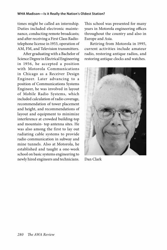
280 The AWA Review
WHA Madison—Is it Really the Nation’s Oldest Station?
times might be called an internship.Duties included electronic mainte-nance, conducting remote broadcasts; and after receiving a First Class Radio-telephone license in 1953, operation of AM, FM, and Television transmitters.
After graduating with a Bachelor of Science Degree in Electrical Engineering in 1956, he accepted a position with Motorola Communications in Chicago as a Receiver Design Engineer. Later advancing to a position of Communications Systems Engineer, he was involved in layout of Mobile Radio Systems, which included calculation of radio coverage, recommendation of tower placement and height, and recommendations of layout and equipment to minimize interference at crowded building-top and mountain- top antenna sites. He was also among the first to lay out radiating cable systems to provide radio communication in subway and mine tunnels. Also at Motorola, he established and taught a one-week school on basic systems engineering to newly hired engineers and technicians.
This school was presented for many years in Motorola engineering offices throughout the country and also in Europe and Asia.
Retiring from Motorola in 1995, current activities include amateur radio, restoring antique radios, and restoring antique clocks and watches.
Dan Clark