Embed Size (px)
Citation preview
NOTES
Module 02
The AutoCAD Civil 3D Environment
In this module, you learn about the user interface components and the working
environment of AutoCAD Civil 3D. Familiarity with the interface is critical to
getting the information you need to create your design. It is important to have
a solid understanding of the Toolspace window, workspaces, template files,
and the help system.
Objectives
After completing this module, you will be able to:
Choose the appropriate workspace for the current task.
Find and modify basic information about civil design components using
the Toolspace window.
Identify various settings and styles in the Settings tab and modify which
styles are active for data using the Prospector tab.
Use the Panorama window to view processing messages, errors, and
modify object data.
Use floating dialog boxes to view and alter settings during a command.
View context sensitive Help.
Create new drawings based on template files.

AutoCAD Civil 3D 2009 Education Curriculum NOTES
02-2
Notes
This module introduces you to the AutoCAD Civil 3D working environment.
You need to understand the user interface and feel comfortable navigating it.
It is important that faculty emphasize the use of the Civil 3D design tools to
create intelligent objects that interact with other objects in the design. Simply
drafting lines or circles to make the drawing look right results in problems
down the road. This is the fundamental difference between AutoCAD as a
drafting tool and AutoCAD Civil 3D as design software.
You should have completed Module 1 on AutoCAD Basics prior to moving
into these exercises. A familiarity with the AutoCAD environment is assumed
and this module focuses on the Civil 3D aspects of the environment.
Data for this module resides in the \AutoCAD Civil 3D 2009 Education
Curriculum\Module 02- AutoCAD Civil 3D 2009 Environment\ folder.
The drawing data for this module is independent of units. You will find the
required drawings in both the\Imperial and \Metric folders.
Student Exercises
The following exercises are provided in step-by-step format. Open the
AutoCAD Civil 3D 2009 program prior to beginning the lesson by double-
clicking the Civil 3D icon on your desktop.
Drawing files in this exercise are unit independent. All drawing names begin
with the letter I.
You are required to open the drawings provided with the exercises.
The exercises in this module are as follows:
1. Workspace and Toolspace Basics
2. The Prospector Tab
3. The Settings Tab
4. The Panorama Window
5. Menus, Floating Dialog Boxes, and Help
6. Using Template Files
Module 02 – AutoCAD Civil 3D Environment NOTES
02-3
AutoCAD Civil 3D Environment
AutoCAD Civil 3D is an object-oriented design environment with defined
interactions between civil design objects. For example, changes made to the
elevations of a surface result in changes to surface profiles and cross sections.
Civil 3D uses major land development components as interactive objects. The
result is a software environment suited to design, with production drafting as a
by-product of the design process.
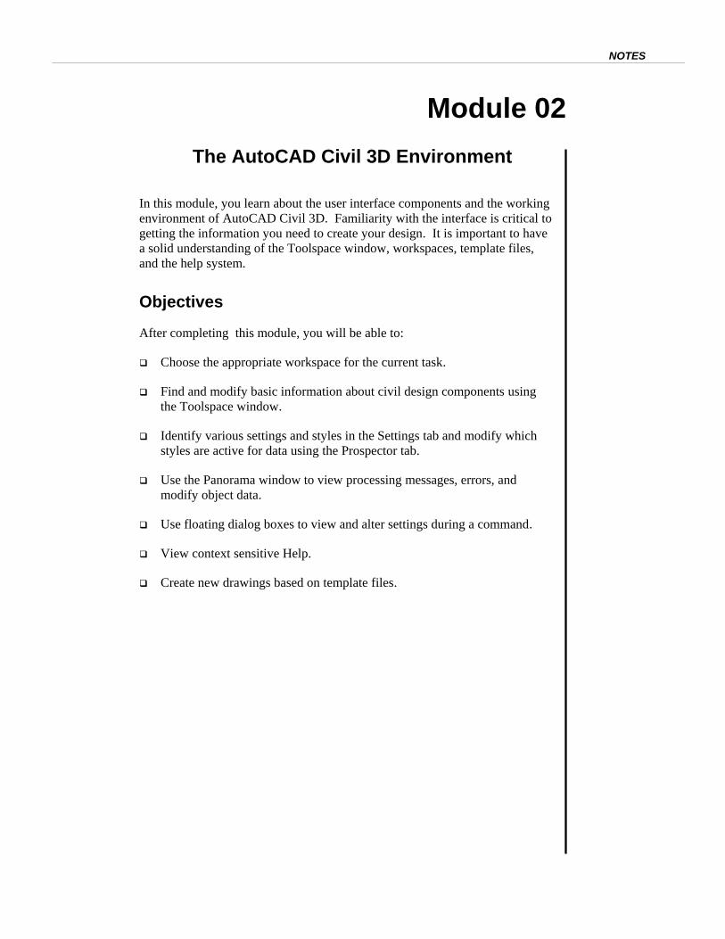
There are several components that make up the AutoCAD Civil 3D
environment as shown in the following image.
It is important to organize the AutoCAD Civil 3D environment efficiently so
you easily find and use the commands you need.
Key Terms
Object -Oriented Object-oriented refers to the programming method used in Civil 3D and
many other programs. Civil engineering components used in site
development and highway design are programmed as “objects” that have
associated properties and actions that often interact with other objects;
for example, surface edits impact existing profiles or cross sections.
Civil 3D Objects Civil 3D objects are programmed into the software with behaviors,
AutoCAD Civil 3D 2009 Education Curriculum NOTES
02-4
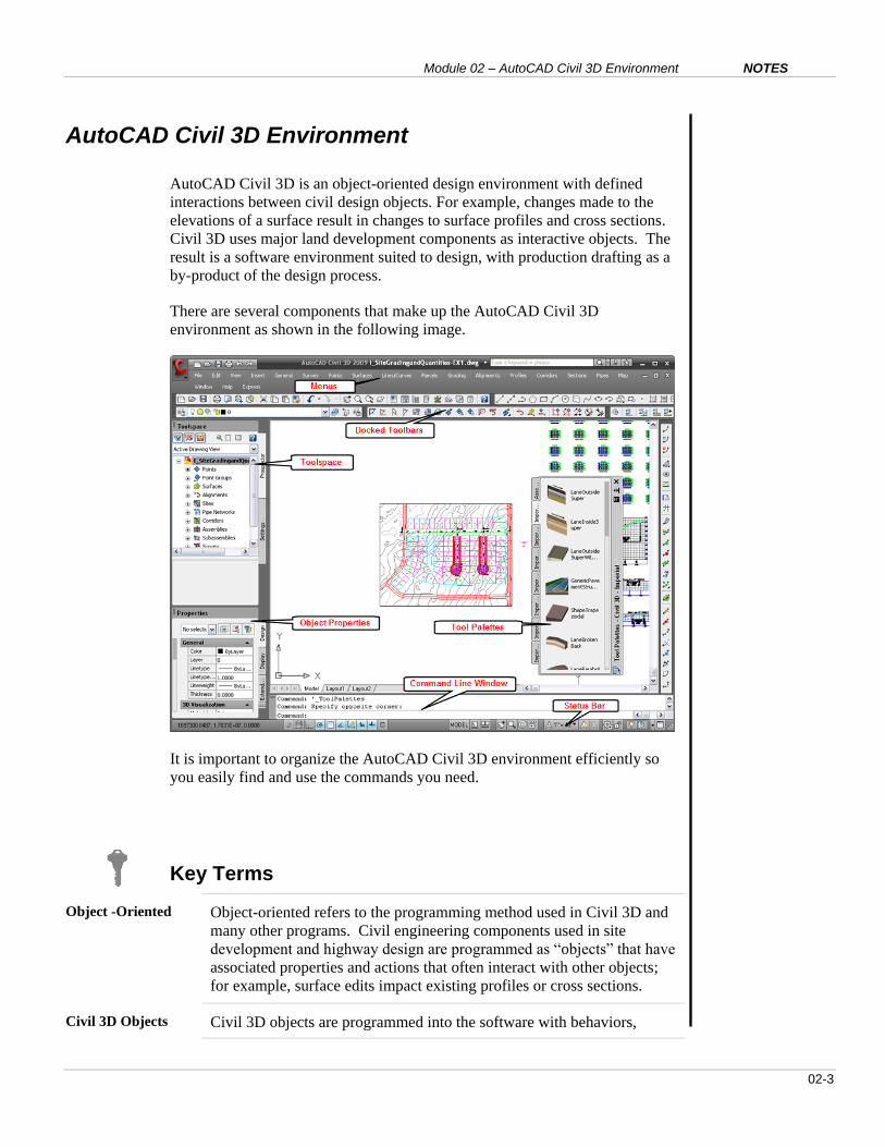
properties, and interactions similar to the real objects that engineers use
in design. The table below shows object names and icons:
Workspace Workspaces are a collection of menus, toolbars, and palettes that load
automatically.
Toolspace The Toolspace window holds the Prospector and Settings tabs and is a
major user interface element that the user must understand.
Template Files Template files can contain standard AutoCAD settings, layers, linetypes,
and text style definitions. In addition, template files can include any
Civil 3D drawing information in either the Settings tree (including Civil
3D settings, styles, label styles, tables, description keys, and point
import/export formats) or the Prospector tree (including any Civil 3D
object, such as point groups).
Module 02 – AutoCAD Civil 3D Environment NOTES
02-5
EXERCISE 1: WORKSPACE AND TOOLSPACE BASICS
In this exercise, you learn about the different workspaces available in Civil 3D,
as well as the major interface window, Toolspace.
For this exercise, open …\Module 2 – AutoCAD Civil 3D
Environment\I_AutoCADCivil3DEnvironment-EX1.dwg.
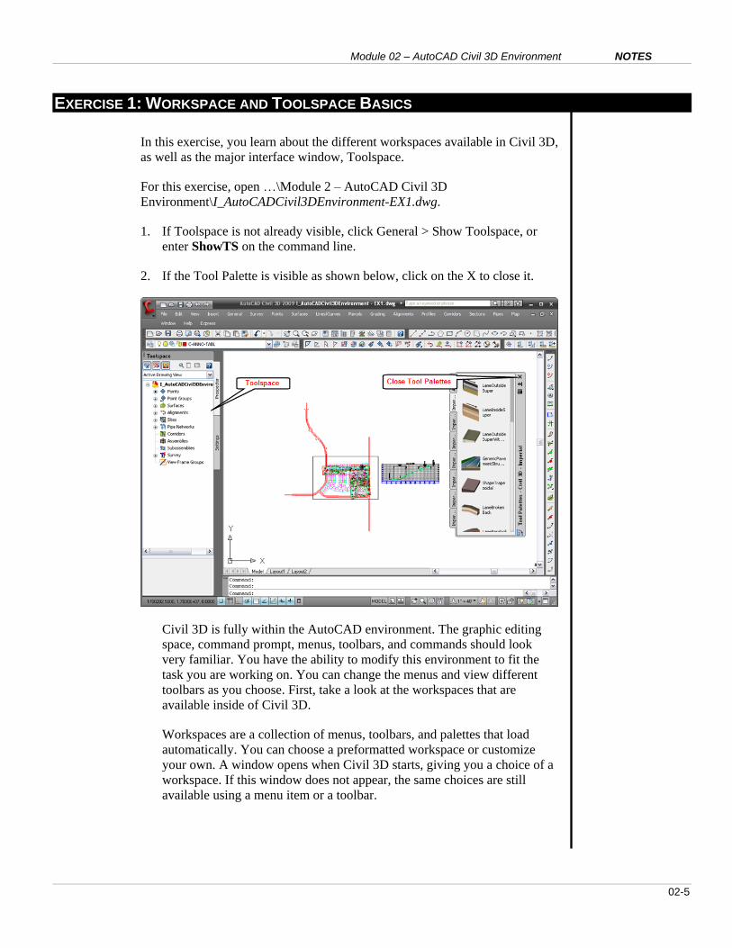
1. If Toolspace is not already visible, click General > Show Toolspace, or
enter ShowTS on the command line.
2. If the Tool Palette is visible as shown below, click on the X to close it.
Civil 3D is fully within the AutoCAD environment. The graphic editing
space, command prompt, menus, toolbars, and commands should look
very familiar. You have the ability to modify this environment to fit the
task you are working on. You can change the menus and view different
toolbars as you choose. First, take a look at the workspaces that are
available inside of Civil 3D.
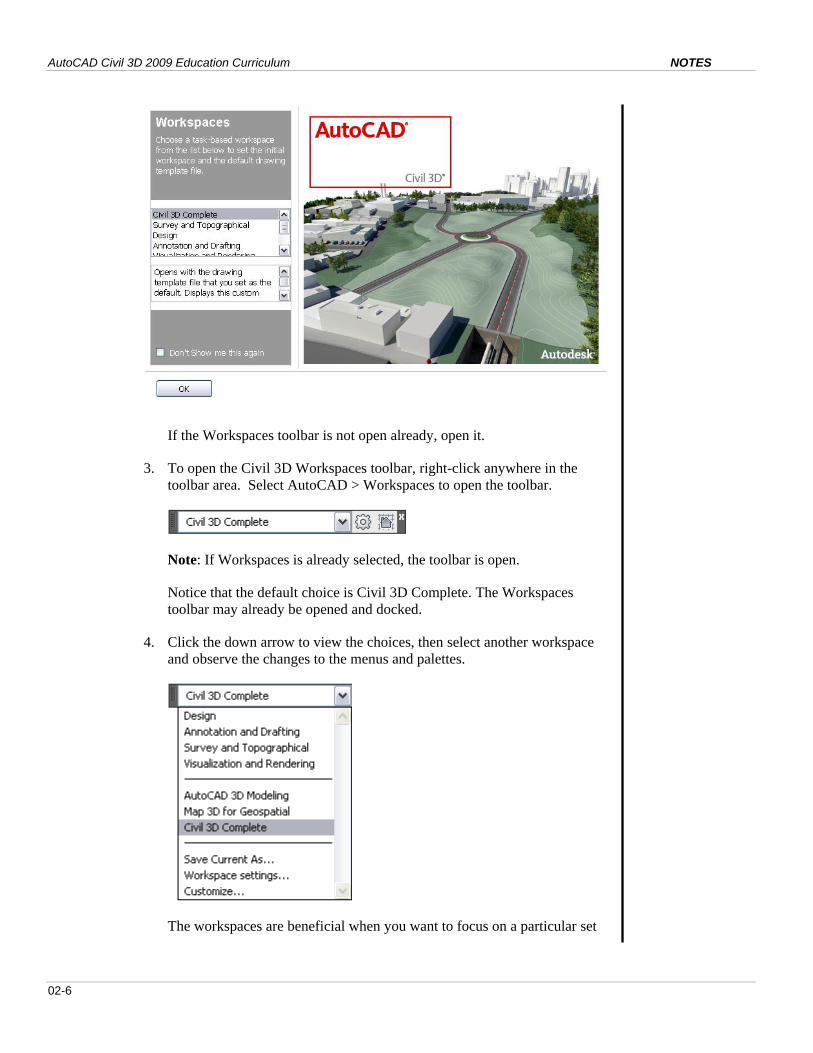
Workspaces are a collection of menus, toolbars, and palettes that load
automatically. You can choose a preformatted workspace or customize
your own. A window opens when Civil 3D starts, giving you a choice of a
workspace. If this window does not appear, the same choices are still
available using a menu item or a toolbar.
AutoCAD Civil 3D 2009 Education Curriculum NOTES
02-6
If the Workspaces toolbar is not open already, open it.
3. To open the Civil 3D Workspaces toolbar, right-click anywhere in the
toolbar area. Select AutoCAD > Workspaces to open the toolbar.
Note: If Workspaces is already selected, the toolbar is open.
Notice that the default choice is Civil 3D Complete. The Workspaces
toolbar may already be opened and docked.
4. Click the down arrow to view the choices, then select another workspace
and observe the changes to the menus and palettes.
The workspaces are beneficial when you want to focus on a particular set
Module 02 – AutoCAD Civil 3D Environment NOTES
02-7
of tasks, such as working in Map 3D for Geospatial.
5. Return to the Civil 3D Complete workspace when finished.
There are four primary methods of interacting with Civil 3D: 1) the
command line (typing), 2) menus, 3) the graphic screen/mouse, and 4) the
Toolspace window. With knowledge of AutoCAD basics, you are familiar
with the first three types of interaction. The Toolspace window presents an
immense amount of data about the drawing and project simultaneously and
is important to master. The Toolspace window can float or dock, become
semitransparent, and automatically hide itself.
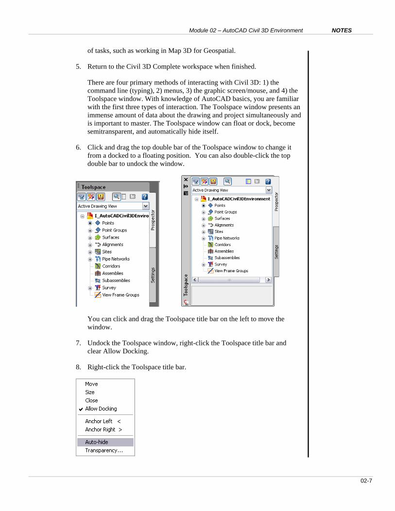
6. Click and drag the top double bar of the Toolspace window to change it
from a docked to a floating position. You can also double-click the top
double bar to undock the window.
You can click and drag the Toolspace title bar on the left to move the
window.
7. Undock the Toolspace window, right-click the Toolspace title bar and
clear Allow Docking.
8. Right-click the Toolspace title bar.
AutoCAD Civil 3D 2009 Education Curriculum NOTES
02-8
9. On the menu, click Auto-hide and remove the mouse from the window.
The Toolspace window disappears leaving the left bar visible. This is a
toggle switch. Repeat the action to undo it. The same can be done by
clicking Auto-hide on the Toolspace title bar.
Major features of this window include the Prospector and Settings tabs on
the right (Prospector is currently active), the icons at the top of the
window, the drop-down list, the objects listed in the Prospector main
window, and the item view list below.
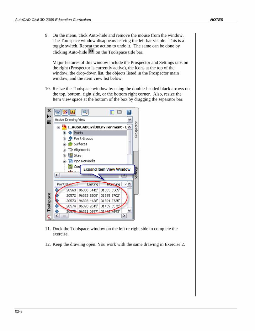
10. Resize the Toolspace window by using the double-headed black arrows on
the top, bottom, right side, or the bottom right corner. Also, resize the
Item view space at the bottom of the box by dragging the separator bar.
11. Dock the Toolspace window on the left or right side to complete the
exercise.
12. Keep the drawing open. You work with the same drawing in Exercise 2.
Module 02 – AutoCAD Civil 3D Environment NOTES
02-9
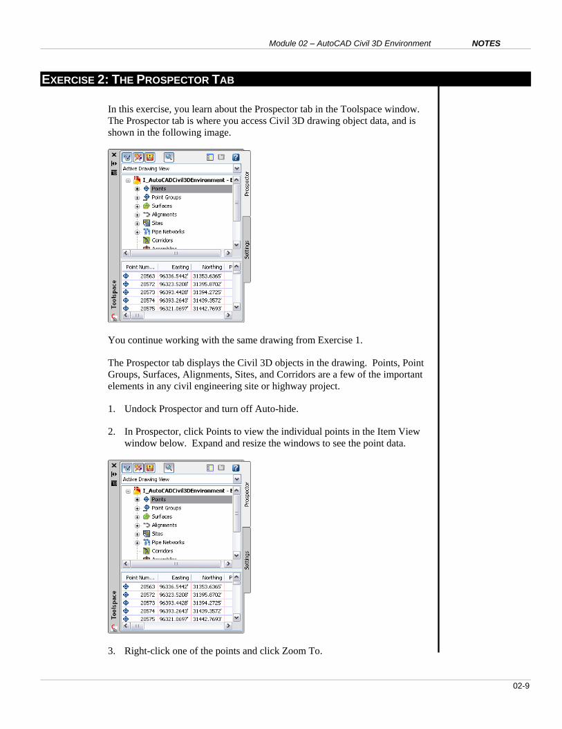
EXERCISE 2: THE PROSPECTOR TAB
In this exercise, you learn about the Prospector tab in the Toolspace window.
The Prospector tab is where you access Civil 3D drawing object data, and is
shown in the following image.
You continue working with the same drawing from Exercise 1.
The Prospector tab displays the Civil 3D objects in the drawing. Points, Point
Groups, Surfaces, Alignments, Sites, and Corridors are a few of the important
elements in any civil engineering site or highway project.
1. Undock Prospector and turn off Auto-hide.
2. In Prospector, click Points to view the individual points in the Item View
window below. Expand and resize the windows to see the point data.
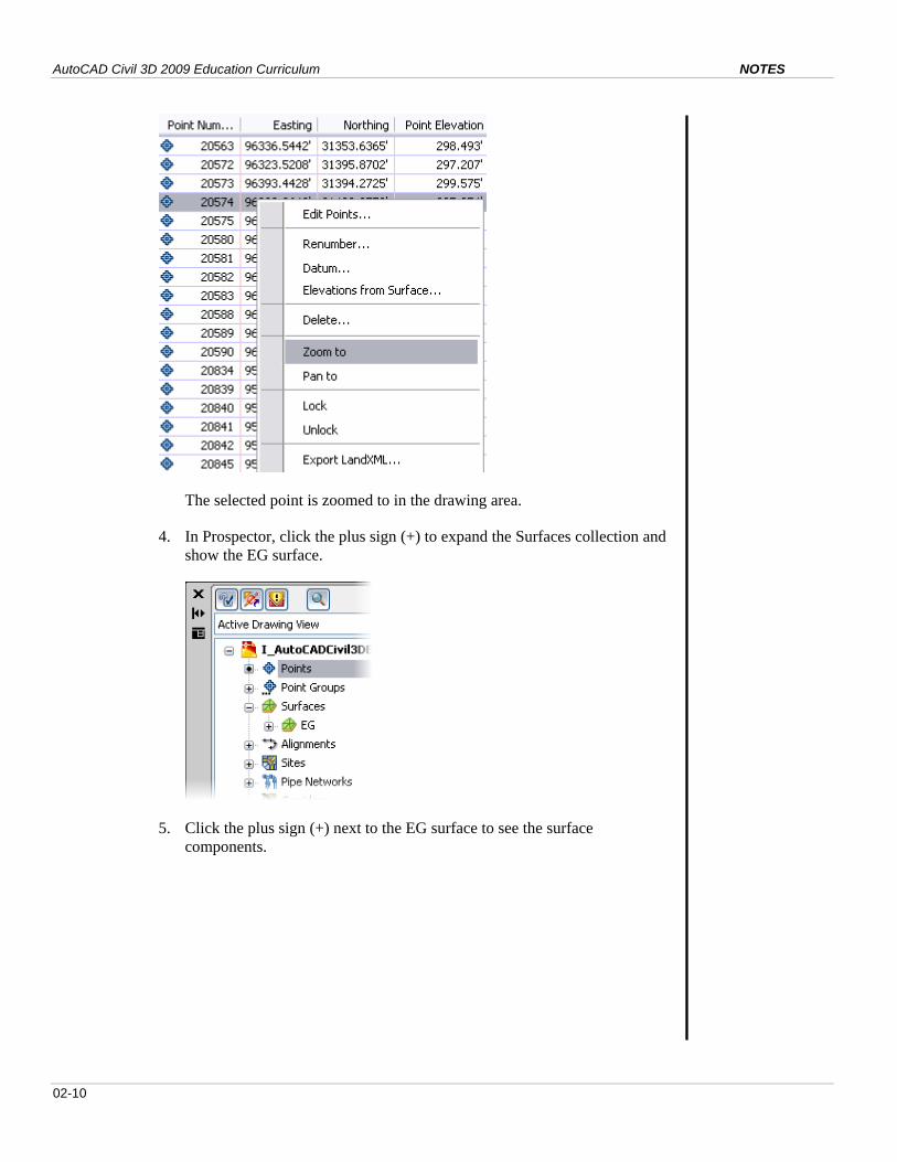
3. Right-click one of the points and click Zoom To.
AutoCAD Civil 3D 2009 Education Curriculum NOTES
02-10
The selected point is zoomed to in the drawing area.
4. In Prospector, click the plus sign (+) to expand the Surfaces collection and
show the EG surface.
5. Click the plus sign (+) next to the EG surface to see the surface
components.

Module 02 – AutoCAD Civil 3D Environment NOTES
02-11
Each surface may have masks or watersheds, but each must be defined by
one or more elements.
6. Click the plus sign (+) next to Definition to view the elements that define
the EG surface.
Notice that the EG surface is defined from boundary and point group data.
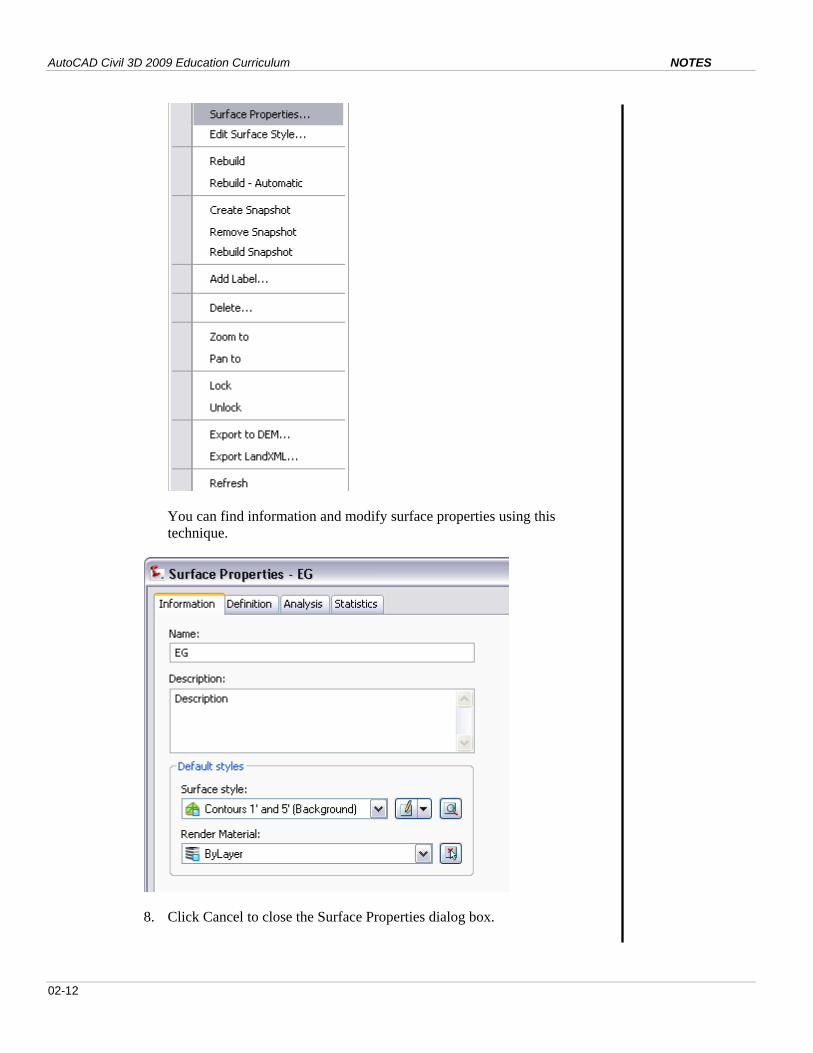
7. In Prospector, right-click EG and click Surface Properties.
AutoCAD Civil 3D 2009 Education Curriculum NOTES
02-12
You can find information and modify surface properties using this
technique.
8. Click Cancel to close the Surface Properties dialog box.
Module 02 – AutoCAD Civil 3D Environment NOTES
02-13
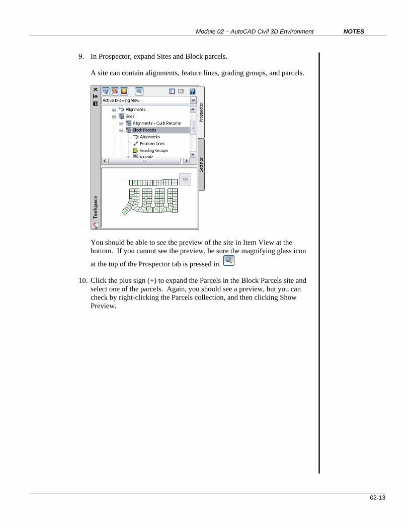
9. In Prospector, expand Sites and Block parcels.
A site can contain alignments, feature lines, grading groups, and parcels.
You should be able to see the preview of the site in Item View at the
bottom. If you cannot see the preview, be sure the magnifying glass icon
at the top of the Prospector tab is pressed in.
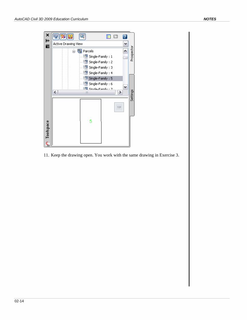
10. Click the plus sign (+) to expand the Parcels in the Block Parcels site and
select one of the parcels. Again, you should see a preview, but you can
check by right-clicking the Parcels collection, and then clicking Show
Preview.
AutoCAD Civil 3D 2009 Education Curriculum NOTES
02-14
11. Keep the drawing open. You work with the same drawing in Exercise 3.
Module 02 – AutoCAD Civil 3D Environment NOTES
02-15
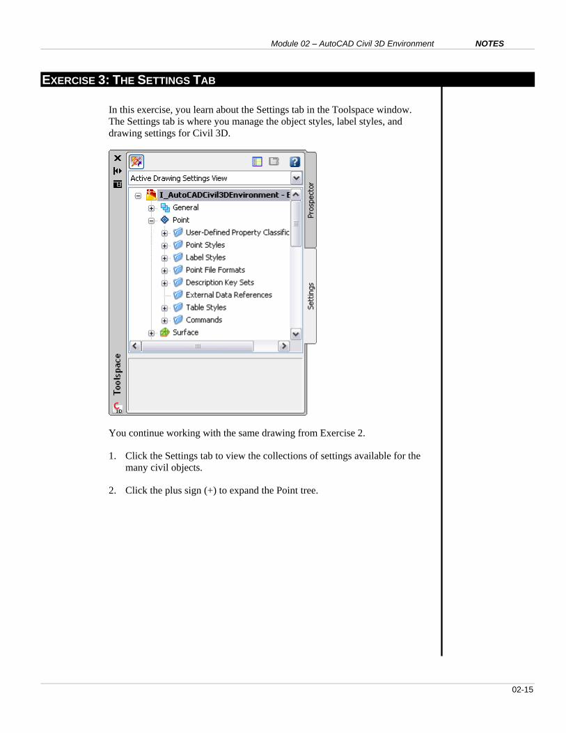
EXERCISE 3: THE SETTINGS TAB
In this exercise, you learn about the Settings tab in the Toolspace window.
The Settings tab is where you manage the object styles, label styles, and
drawing settings for Civil 3D.
You continue working with the same drawing from Exercise 2.
1. Click the Settings tab to view the collections of settings available for the
many civil objects.
2. Click the plus sign (+) to expand the Point tree.
AutoCAD Civil 3D 2009 Education Curriculum NOTES
02-16
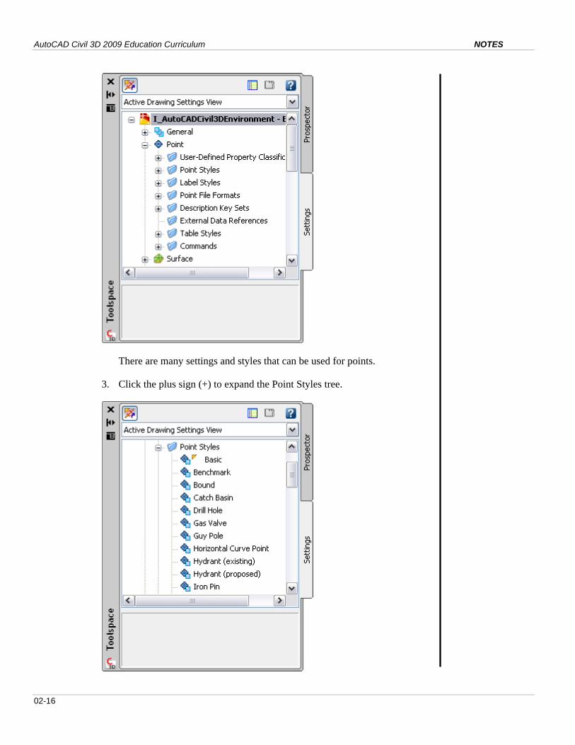
There are many settings and styles that can be used for points.
3. Click the plus sign (+) to expand the Point Styles tree.
Module 02 – AutoCAD Civil 3D Environment NOTES
02-17
The possible styles that can be used for points in this drawing are
displayed. The orange triangle next to the Basic style indicates that this
style is currently in use.
4. Click the minus sign (-) to collapse the Point Styles tree. Click the plus
sign (+) to expand the Label Styles tree.
The Point#-Elevation-Description Style is active.
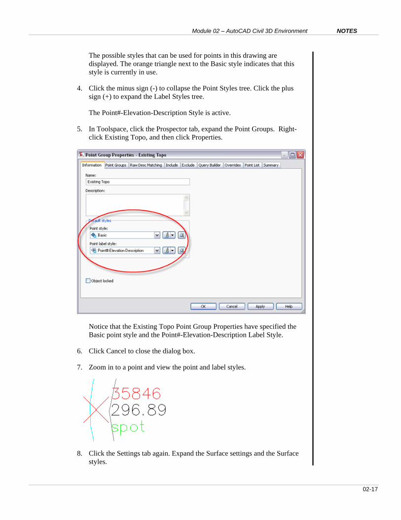
5. In Toolspace, click the Prospector tab, expand the Point Groups. Right-
click Existing Topo, and then click Properties.
Notice that the Existing Topo Point Group Properties have specified the
Basic point style and the Point#-Elevation-Description Label Style.
6. Click Cancel to close the dialog box.
7. Zoom in to a point and view the point and label styles.
8. Click the Settings tab again. Expand the Surface settings and the Surface
styles.
AutoCAD Civil 3D 2009 Education Curriculum NOTES
02-18
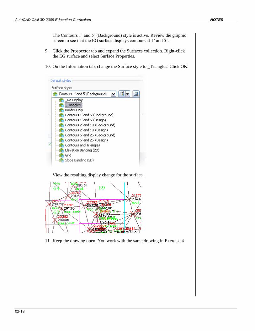
The Contours 1’ and 5’ (Background) style is active. Review the graphic
screen to see that the EG surface displays contours at 1’ and 5’.
9. Click the Prospector tab and expand the Surfaces collection. Right-click
the EG surface and select Surface Properties.
10. On the Information tab, change the Surface style to _Triangles. Click OK.
View the resulting display change for the surface.
11. Keep the drawing open. You work with the same drawing in Exercise 4.
Module 02 – AutoCAD Civil 3D Environment NOTES
02-19
EXERCISE 4: THE PANORAMA WINDOW
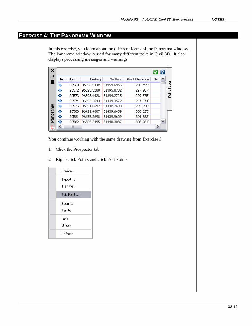
In this exercise, you learn about the different forms of the Panorama window.
The Panorama window is used for many different tasks in Civil 3D. It also
displays processing messages and warnings.
You continue working with the same drawing from Exercise 3.
1. Click the Prospector tab.
2. Right-click Points and click Edit Points.
AutoCAD Civil 3D 2009 Education Curriculum NOTES
02-20
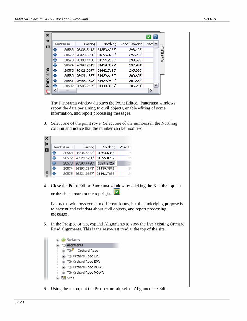
The Panorama window displays the Point Editor. Panorama windows
report the data pertaining to civil objects, enable editing of some
information, and report processing messages.
3. Select one of the point rows. Select one of the numbers in the Northing
column and notice that the number can be modified.
4. Close the Point Editor Panorama window by clicking the X at the top left
or the check mark at the top right.
Panorama windows come in different forms, but the underlying purpose is
to present and edit data about civil objects, and report processing
messages.
5. In the Prospector tab, expand Alignments to view the five existing Orchard
Road alignments. This is the east-west road at the top of the site.
6. Using the menu, not the Prospector tab, select Alignments > Edit
Module 02 – AutoCAD Civil 3D Environment NOTES
02-21
Alignment Geometry. At this point, the command window prompts you to
select an alignment to edit.
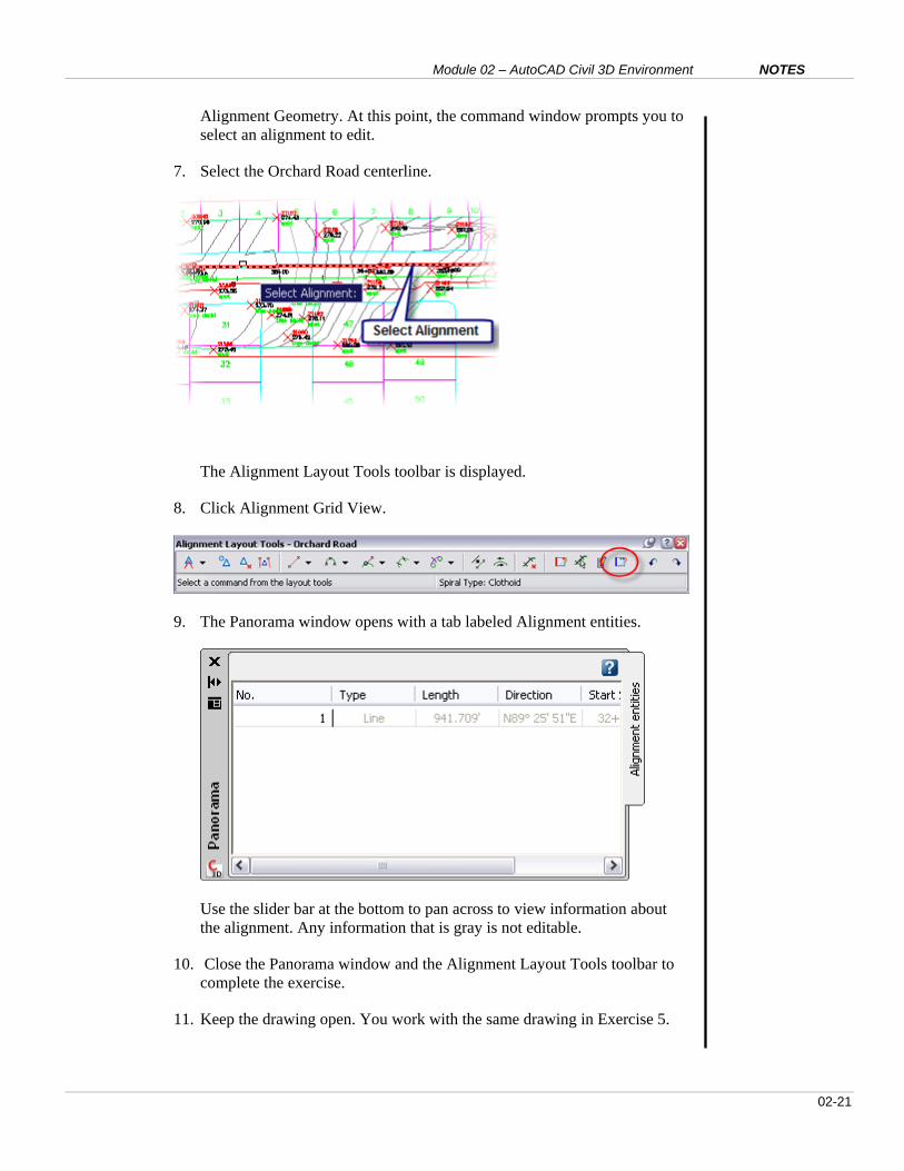
7. Select the Orchard Road centerline.
The Alignment Layout Tools toolbar is displayed.
8. Click Alignment Grid View.
9. The Panorama window opens with a tab labeled Alignment entities.
Use the slider bar at the bottom to pan across to view information about
the alignment. Any information that is gray is not editable.
10. Close the Panorama window and the Alignment Layout Tools toolbar to
complete the exercise.
11. Keep the drawing open. You work with the same drawing in Exercise 5.
AutoCAD Civil 3D 2009 Education Curriculum NOTES
02-22
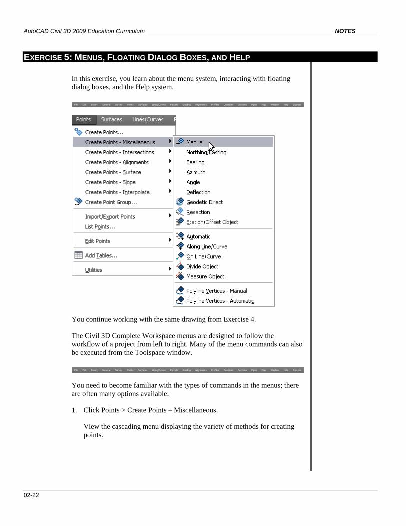
EXERCISE 5: MENUS, FLOATING DIALOG BOXES, AND HELP
In this exercise, you learn about the menu system, interacting with floating
dialog boxes, and the Help system.
You continue working with the same drawing from Exercise 4.
The Civil 3D Complete Workspace menus are designed to follow the
workflow of a project from left to right. Many of the menu commands can also
be executed from the Toolspace window.
You need to become familiar with the types of commands in the menus; there
are often many options available.
1. Click Points > Create Points – Miscellaneous.
View the cascading menu displaying the variety of methods for creating
points.
Module 02 – AutoCAD Civil 3D Environment NOTES
02-23
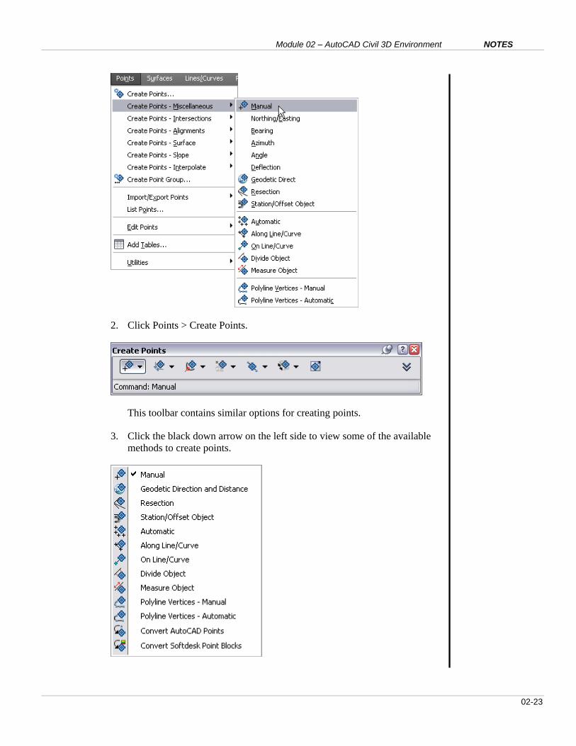
2. Click Points > Create Points.
This toolbar contains similar options for creating points.
3. Click the black down arrow on the left side to view some of the available
methods to create points.
AutoCAD Civil 3D 2009 Education Curriculum NOTES
02-24
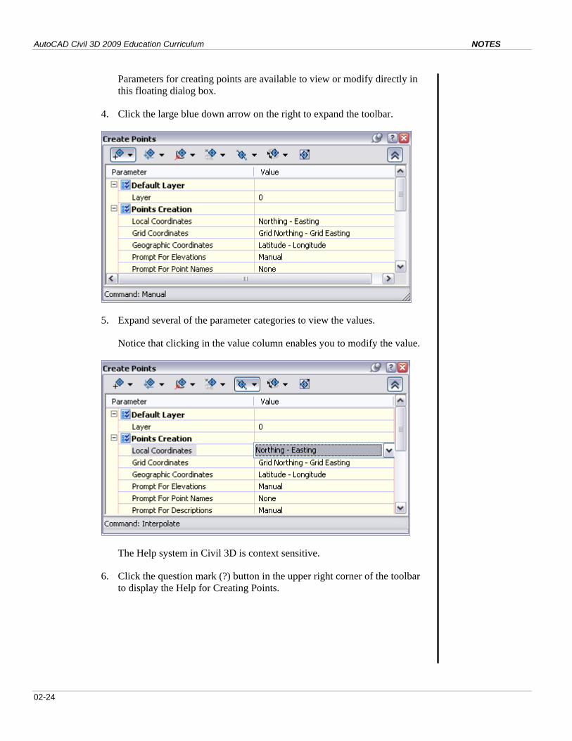
Parameters for creating points are available to view or modify directly in
this floating dialog box.
4. Click the large blue down arrow on the right to expand the toolbar.
5. Expand several of the parameter categories to view the values.
Notice that clicking in the value column enables you to modify the value.
The Help system in Civil 3D is context sensitive.
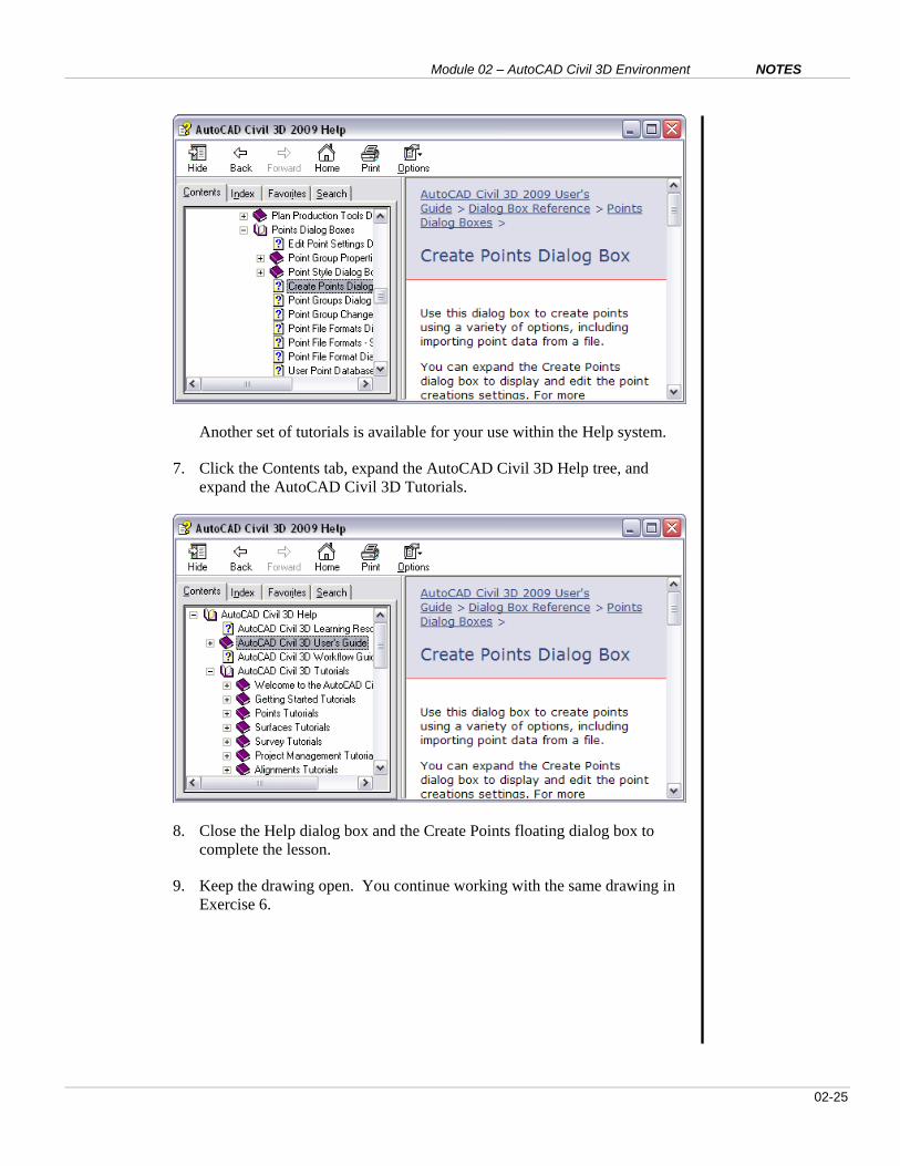
6. Click the question mark (?) button in the upper right corner of the toolbar
to display the Help for Creating Points.
Module 02 – AutoCAD Civil 3D Environment NOTES
02-25
Another set of tutorials is available for your use within the Help system.
7. Click the Contents tab, expand the AutoCAD Civil 3D Help tree, and
expand the AutoCAD Civil 3D Tutorials.
8. Close the Help dialog box and the Create Points floating dialog box to
complete the lesson.
9. Keep the drawing open. You continue working with the same drawing in
Exercise 6.
AutoCAD Civil 3D 2009 Education Curriculum NOTES
02-26
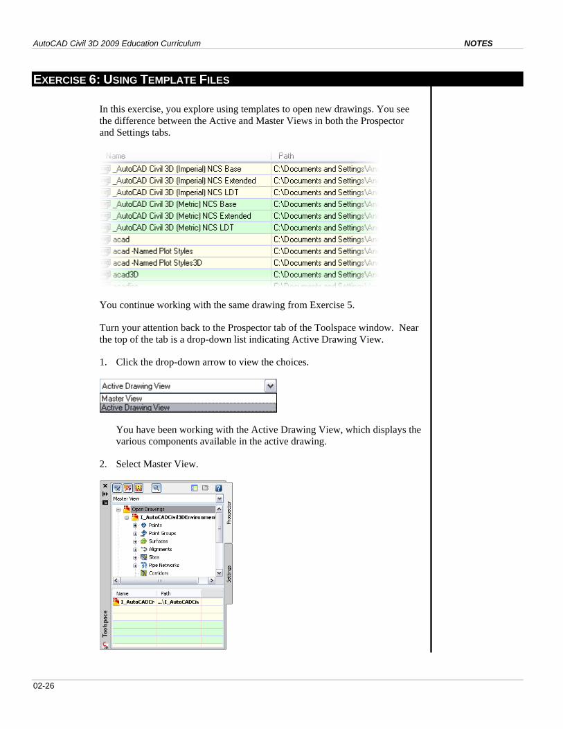
EXERCISE 6: USING TEMPLATE FILES
In this exercise, you explore using templates to open new drawings. You see
the difference between the Active and Master Views in both the Prospector
and Settings tabs.
You continue working with the same drawing from Exercise 5.
Turn your attention back to the Prospector tab of the Toolspace window. Near
the top of the tab is a drop-down list indicating Active Drawing View.
1. Click the drop-down arrow to view the choices.
You have been working with the Active Drawing View, which displays the
various components available in the active drawing.
2. Select Master View.
Module 02 – AutoCAD Civil 3D Environment NOTES
02-27
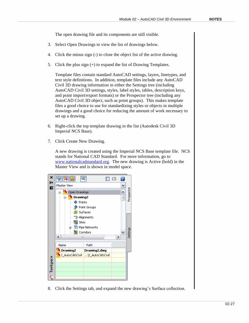
The open drawing file and its components are still visible.
3. Select Open Drawings to view the list of drawings below.
4. Click the minus sign (-) to close the object list of the active drawing.
5. Click the plus sign (+) to expand the list of Drawing Templates.
Template files contain standard AutoCAD settings, layers, linetypes, and
text style definitions. In addition, template files include any AutoCAD
Civil 3D drawing information in either the Settings tree (including
AutoCAD Civil 3D settings, styles, label styles, tables, description keys,
and point import/export formats) or the Prospector tree (including any
AutoCAD Civil 3D object, such as point groups). This makes template
files a good choice to use for standardizing styles or objects in multiple
drawings and a good choice for reducing the amount of work necessary to
set up a drawing.
6. Right-click the top template drawing in the list (Autodesk Civil 3D
Imperial NCS Base).
7. Click Create New Drawing.
A new drawing is created using the Imperial NCS Base template file. NCS
stands for National CAD Standard. For more information, go to
www.nationalcadstandard.org. The new drawing is Active (bold) in the
Master View and is shown in model space.
8. Click the Settings tab, and expand the new drawing’s Surface collection.
AutoCAD Civil 3D 2009 Education Curriculum NOTES
02-28
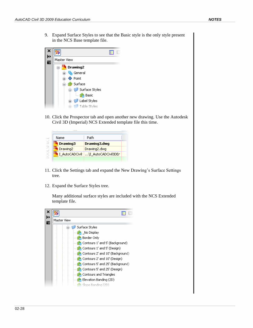
9. Expand Surface Styles to see that the Basic style is the only style present
in the NCS Base template file.
10. Click the Prospector tab and open another new drawing. Use the Autodesk
Civil 3D (Imperial) NCS Extended template file this time.
11. Click the Settings tab and expand the New Drawing’s Surface Settings
tree.
12. Expand the Surface Styles tree.
Many additional surface styles are included with the NCS Extended
template file.

Module 02 – AutoCAD Civil 3D Environment NOTES
02-29
Questions
1. Define a Workspace.
2. Describe a quick way to zoom in to a particular point using the
Prospector tab.
3. Use Toolspace and I_AutoCAD3DEnvironment.dwg to name three types
of entities that define a surface.
4. True or False: Point styles and label styles are defined in the Settings tab,
but assigned in the Prospector tab.
5. What is a template file?
Answers
The answers to the questions are as follows:
1. A workspace in Civil 3D is a collection of menus, toolbars, and palettes
that will automatically load when you choose a particular workspace.
The default workspace is the Civil 3D Complete, but many others are
available depending on the type of task you want to perform.
2. Click Points, look in the Item View list at the bottom of the Prospector
tab to find the point of interest. Right-click the point row, and then click
Zoom To.
3. See the figure below for the answer:
4. True.
5. Template files can contain standard AutoCAD settings, layers, lines, and
text. In addition, template files can include any AutoCAD Civil 3D
drawing information in either the Settings tree (including Civil 3D
settings, styles, label styles, tables, description keys, and point
import/export formats) or the Prospector tree (including any Civil 3D

AutoCAD Civil 3D 2009 Education Curriculum NOTES
02-30
object, such as point groups).

Module 02 – AutoCAD Civil 3D Environment NOTES
02-31
Module Summary
This module focused on introducing the student to the user interface and
design environment for AutoCAD Civil 3D. Civil 3D design projects have
components that are interactive; therefore, it is important for a user to
understand where to view or edit data quickly.