Embed Size (px)
Citation preview
The ATF Damping Ring BPM Upgrade
- Overview and Status -
Manfred Wendt
Fermilab
for the ATF DR BPM Upgrade Collaboration
N. Terunuma, J. Urakawa (KEK)
C. Briegel, N. Eddy, B. Fellenz, E. Gianfelice, P. Prieto, R. Rechenmacher, D. Slimmer,
D. Voy, D. Zhang (Fermilab)
4/18/2009 1TILC09 Workshop
Agenda
• Motivation• The ATF Damping Ring• Details of the BPM read-out
electronics upgrade• Beam studies and
performance measurements• Conclusions
4/18/2009 TILC09 Workshop 2
Motivation
• ILC damping ring R&D at KEK’s Accelerator Test Facility (ATF):– Investigation of the beam damping process (damping wiggler,
minimization of the damping time, etc.)
– Goal: generation and extraction of a low emittance beam (εvert < 2 pm) at the nominal ILC bunch charge
• A major tool for low emittance corrections: a high resolution BPM system– Optimization of the closed-orbit, beam-based alignment (BBA) studies
to investigate BPM offsets and calibration.
– Correction of non-linear field effects, i.e. coupling, chromaticity,…
– Fast global orbit feedback(?)
– Necessary: a state-or-the-art BPM system, utilizing • a broadband turn-by-turn mode (< 10 µm resolution)• a narrowband mode with high resolution (~ 100 nm range)
4/18/2009 TILC09 Workshop 3
Collaboration “History”
• ATF Damping Ring Beam Position Monitor System– Button style BPM pickup stations– Original read-out electronics:
Analog signal processing, no TBT, intensity dependence
• 2006: M. Ross & SLAC team– Analog downconverter & digital receiver (Echotek)
read-out system, prototype achieves 1-2 µm resolution
• 2007/8: KEK/SLAC/Fermilab collaboration– 20 BPMs in both arcs equipped with new read-out system– EPICS & LabVIEW software– Few µm resolution in TBT, ~200 nm narrowband– First test of an integrated automatic calibration system
• 2009: KEK/Fermilab– Improvements on the downconverter 4/18/2009 TILC09 Workshop 4
The ATF Damping Ring
4/18/2009 TILC09 Workshop 5
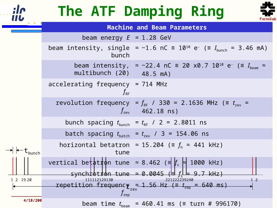
Machine and Beam Parameters
beam energy E = 1.28 GeV
beam intensity, single bunch ≈ ~1.6 nC ≡ 1010 e- (≡ Ibunch ≈ 3.46 mA)
beam intensity, multibunch (20)
≈ ~22.4 nC ≡ 20 x0.7 1010 e- (≡ Ibeam ≈ 48.5 mA)
accelerating frequency fRF = 714 MHz
revolution frequency frev = fRF / 330 = 2.1636 MHz (≡ trev = 462.18 ns)
bunch spacing tbunch = tRF / 2 = 2.8011 ns
batch spacing tbatch = trev / 3 = 154.06 ns
horizontal betatron tune ≈ 15.204 (≡ fh ≈ 441 kHz)
vertical betatron tune ≈ 8.462 (≡ fv ≈ 1000 kHz)
synchrotron tune ≈ 0.0045 (≡ fs ≈ 9.7 kHz)
repetition frequency frep = 1.56 Hz (≡ trep = 640 ms)
beam time tbeam = 460.41 ms (≡ turn # 996170)
1 2 19 20 1 2111 112 129 130 221 222 239 240
trev
tbunch

The ATF Damping Ring
4/18/2009 TILC09 Workshop 6
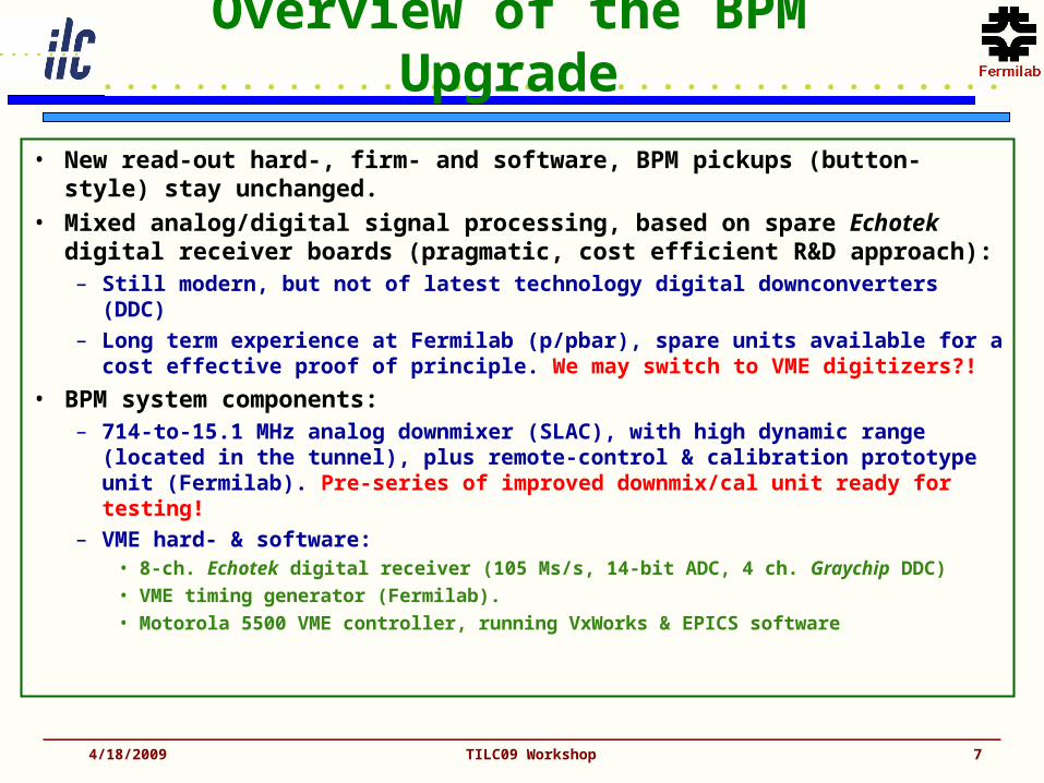
Overview of the BPM Upgrade
• New read-out hard-, firm- and software, BPM pickups (button-style) stay unchanged.
• Mixed analog/digital signal processing, based on spare Echotek digital receiver boards (pragmatic, cost efficient R&D approach):– Still modern, but not of latest technology digital downconverters (DDC)
– Long term experience at Fermilab (p/pbar), spare units available for a cost effective proof of principle. We may switch to VME digitizers?!
• BPM system components:– 714-to-15.1 MHz analog downmixer (SLAC), with high dynamic range
(located in the tunnel), plus remote-control & calibration prototype unit (Fermilab). Pre-series of improved downmix/cal unit ready for testing!
– VME hard- & software:• 8-ch. Echotek digital receiver (105 Ms/s, 14-bit ADC, 4 ch. Graychip DDC) • VME timing generator (Fermilab).• Motorola 5500 VME controller, running VxWorks & EPICS software
4/18/2009 TILC09 Workshop 7
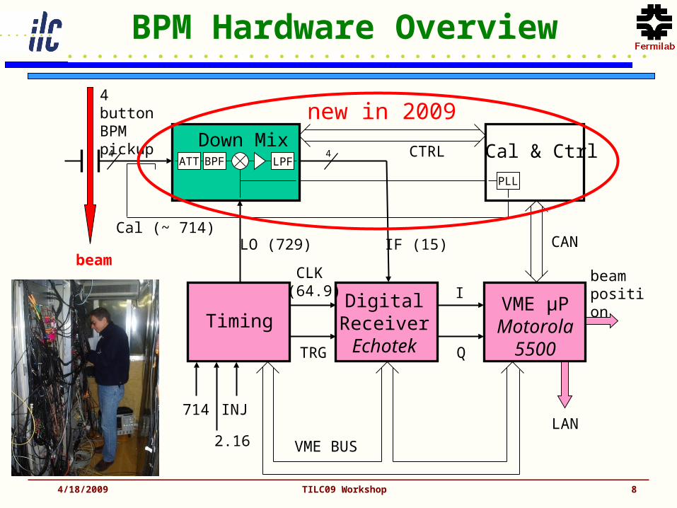
BPM Hardware Overview
4/18/2009 TILC09 Workshop 8
BPF LPF
714
2.16
INJ
Down Mix
Cal (~ 714)
Timing
LO (729)
CLK (64.9)
TRG
Digital ReceiverEchotek
VME µPMotorola
5500Q
Ibeamposition
4 buttonBPMpickup
IF (15)beam
VME BUS
CTRL
LAN
PLL
4ATT
Cal & Ctrl4
CAN
new in 2009

4/18/2009 TILC09 Workshop 9
Button-style BPM Pickup
Button:transferimpedance
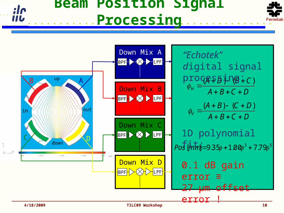
Beam Position Signal Processing
4/18/2009 TILC09 Workshop 10
AB
C D
up
down
outin
DCBA
CBDAH
)()(
DCBA
DCBAV
)()(
53 79.700.135.9][ mmPos
BPF LPF
Down Mix A
BPF LPF
Down Mix B
BPF LPF
Down Mix C
BPF LPF
Down Mix D
“Echotek” digital signal processing:
1D polynomial fit:
0.1 dB gain error ≡
27 µm offset error !

Analog Signal Processing
• 4-ch. Analog downmixer– IN: 714, LO: 729.1, IF: 15.1 MHz
– CAN-bus controlled gain, attenuator & cal system
– Gain switchable, low-noise, high IP3 input gain stage
– Image rejection (SSB) mixer
– 27dB gain, ultralinear IF stage
4/18/2009 TILC09 Workshop 11
BPF
CF: 714 MHzBW: 10 MHz
LNA
G: 14/-2 dBNF: 1 dB
BPF
CF: 15.1 MHzBW: 3 MHz
LNA
G: 30 dBNF: 2.7 dB
SSB Mixer
IN714 MHz
OUT15.145 MHz
LO729.145 MHz
00
900
LPFATT
BW: 30 MHz
0…28 dB4 dB steps1.6 dB loss
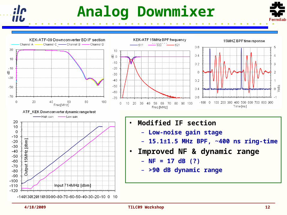
Analog Downmixer
• Modified IF section– Low-noise gain stage
– 15.1±1.5 MHz BPF, ~400 ns ring-time
• Improved NF & dynamic range– NF = 17 dB (?)
– >90 dB dynamic range
4/18/2009 TILC09 Workshop 12

Analog Downmixer (cont.)
4/18/2009 TILC09 Workshop 13
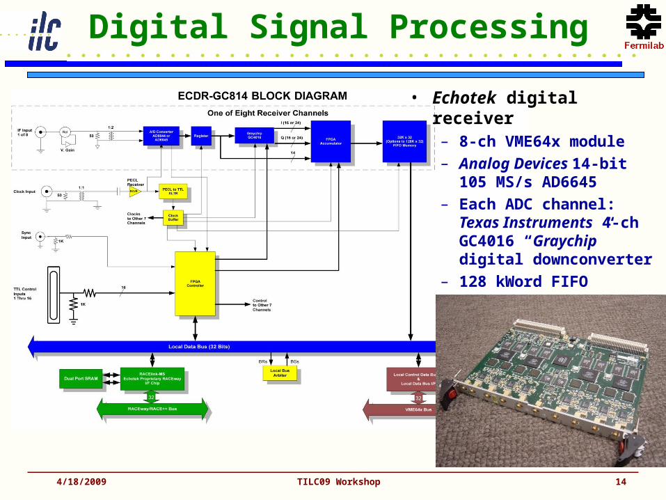
Digital Signal Processing
4/18/2009 TILC09 Workshop 14
• Echotek digital receiver– 8-ch VME64x module
– Analog Devices 14-bit 105 MS/s AD6645
– Each ADC channel:Texas Instruments 4-ch GC4016 “Graychip” digital downconverter
– 128 kWord FIFO
4/18/2009 TILC09 Workshop 15
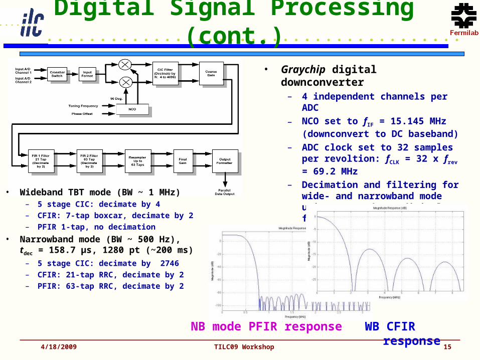
Digital Signal Processing (cont.)
NB mode PFIR response WB CFIR response
• Wideband TBT mode (BW ~ 1 MHz)– 5 stage CIC: decimate by 4
– CFIR: 7-tap boxcar, decimate by 2
– PFIR 1-tap, no decimation
• Narrowband mode (BW ~ 500 Hz),tdec = 158.7 µs, 1280 pt (~200 ms)
– 5 stage CIC: decimate by 2746
– CFIR: 21-tap RRC, decimate by 2
– PFIR: 63-tap RRC, decimate by 2
• Graychip digital downconverter– 4 independent channels per ADC
– NCO set to fIF = 15.145 MHz(downconvert to DC baseband)
– ADC clock set to 32 samples per revoltion: fCLK = 32 x frev = 69.2 MHz
– Decimation and filtering for wide- and narrowband mode using CIC and FIR digital filters
– Simultaneous DDC operation of beam and calibration signals!
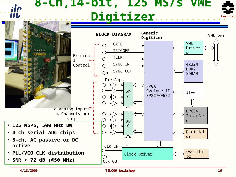
8-Ch,14-bit, 125 MS/s VME Digitizer
4/18/2009 TILC09 Workshop 16
BLOCK DIAGRAM
FPGACyclone IIEP2C70F672
VMEDrivers
4x32MDDR2SDRAM
JTAG
EPCS4Interface
VME bus
Oscillator
Oscillator
CLK IN
CLK OUT
GATE
TRIGGER
TCLK
SYNC IN
SYNC OUT
Generic Digitizer
External Control
Clock Driver
ADC
ADC
Pre-Amps
8 Analog Inputs 4 Channels per Chip
• 125 MSPS, 500 MHz BW
• 4-ch serial ADC chips
• 8-ch, AC passive or DC active
• PLL/VCO CLK distribution
• SNR > 72 dB (@50 MHz)
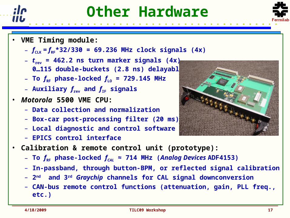
Other Hardware
4/18/2009 TILC09 Workshop 17
• VME Timing module:– fCLK = fRF*32/330 = 69.236 MHz clock signals (4x)
– trev = 462.2 ns turn marker signals (4x), 0…115 double-buckets (2.8 ns) delayable
– To fRF phase-locked fLO = 729.145 MHz
– Auxiliary frev and fIF signals
• Motorola 5500 VME CPU: – Data collection and normalization
– Box-car post-processing filter (20 ms)
– Local diagnostic and control software
– EPICS control interface
• Calibration & remote control unit (prototype):– To fRF phase-locked fCAL ≈ 714 MHz (Analog Devices ADF4153)
– In-passband, through button-BPM, or reflected signal calibration
– 2nd and 3rd Graychip channels for CAL signal downconversion
– CAN-bus remote control functions (attenuation, gain, PLL freq., etc.)

Calibration Schema
4/18/2009 TILC09 Workshop 18
• 2 calibration tones:– 714 + ε MHz
– 714 – ε MHz
– In passband of the downconverter
– Coupled through the button BPM
– Alternative: Reflected CAL signal
• On-line calibration– In presents of beam
signals
– Available only in narrowband mode
– Using separate Graychip channels
Calibration Details
4/18/2009 TILC09 Workshop 19
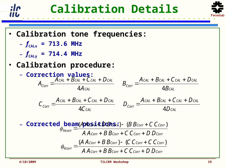
• Calibration tone frequencies:– fCALx = 713.6 MHz
– fCALy = 714.4 MHz
• Calibration procedure:– Correction values:
– Corrected beam positions:
CAL
CALCALCALCAL
Corr A
DCBAA
4
CAL
CALCALCALCAL
Corr B
DCBAB
4
CAL
CALCALCALCAL
Corr C
DCBAC
4
CAL
CALCALCALCAL
Corr D
DCBAD
4
CorrCorrCorrCorr
CorrCorrCorrCorr
Hcorr DDCCBBAA
CCBBDDAA
)()(
CorrCorrCorrCorr
CorrCorrCorrCorr
Vcorr DDCCBBAA
CCCCBBAA
)()(

CAL System Test
• Calibration on, datalogger on
• Comparing uncorrected, corrected (coupled-through), and corrected (reflected)
• Introduce large 3 & 1 dB gain errors.
• Automatic correction compensates the gain error almost completely!!
• Corrected beam position shows a slight increase of the RMS error (to be further studies!).
4/18/2009 TILC09 Workshop 20
3dB1dB
3dB 1dB

Software Components
4/18/2009 TILC09 Workshop 21
VMEECAN-2
PMC (1x)
VMETimingK-TGF
(1x)
VMEEchotek
(12x)
CLK (64.9)
TRG(Gate)
A
B
C
D
714
2.16
INJ(BIS)
729
CAN
ClassADC
Interrupt
I/Q Data
DDC Configure
ClassKTGF
Bucket Delay
Turn Data
Sample Count
ClassCALBox
Control
Status
ClassATFBPM
ClassATFBPM
CAL
Control
Status
Sample
Control
Interrupt
Control
Pos/ Int Data
EPICSIOC
Control
Status
Flash
WB / NB
Single/Multi-turn
Diag. Mode
Bucket Delay
Turn Delay
Diagnostic
Flash
Orbit
Multi-turn
VME Hardware Motorola 5500 µP Software (VxWorks)
Ethernet
22
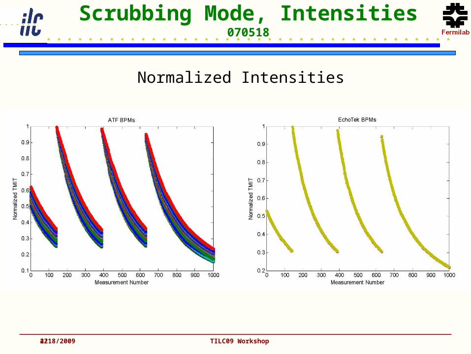
Scrubbing Mode, Intensities070518
Normalized Intensities
4/18/2009 TILC09 Workshop

23
Scrubbing Mode, Positions070518
± 700 um
± 700 um
± 25 um
± 15 um
4/18/2009 TILC09 Workshop
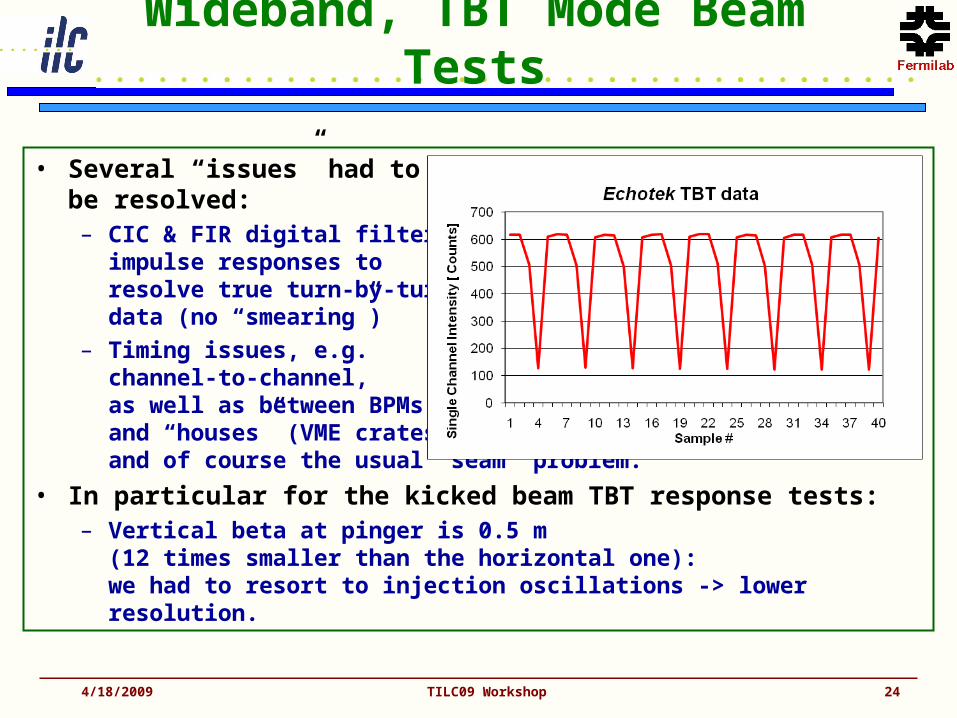
Wideband, TBT Mode Beam Tests
• Several “issues” had to be resolved:– CIC & FIR digital filter
impulse responses to resolve true turn-by-turn data (no “smearing”)
– Timing issues, e.g. channel-to-channel, as well as between BPMs and “houses” (VME crates); and of course the usual “seam” problem.
• In particular for the kicked beam TBT response tests:– Vertical beta at pinger is 0.5 m
(12 times smaller than the horizontal one): we had to resort to injection oscillations -> lower resolution.
4/18/2009 TILC09 Workshop 24

Kicked Beam Tests (May 2007)
4/18/2009 TILC09 Workshop 25
• Turn-by-Turn data BPM #36 (pinger: On)• Identifying hor. and vert. tune lines (387 kHz, 1.212 MHz).• Observed short time, broadband TBT resolution: few µm!
• Observation of “fake” harmonics at n x 10 kHz (not fs), due to power supply EMI in the analog downconverter unit!
vert. tune
hor. tunen x 10 kHz “fake” harmonics

TBT Fourier Analysis
• TBT data at the jth BPM following a single kick in the z-plane (z ≡ x, y):
– with turn number , constant of motion (periodic phase function)
• Twiss functions:
Fourier component of zj
• Amplitude fit:
4/18/2009 TILC09 Workshop 26
..2
1 )2( cceAez niQz
ijz
jn
jzjz
zizz eAA ||
zzz Q
n
22 ||/|)(| zzjjz AQZ zj
jz Z )arg(
)( zj QZ
j zj
j
jz
z QZA
2
0
2
|)(|/1
/1||

Comp.: Measurements vs. Model
• MAD8 model (M. Woodley, marginal differences wrt. Kuroda SAD model).
• Nearby quadrupole trim coil scan (May 2008).• TBT Fourier analysis, amplitude by fit to beta measured
through trim coil scan (April 2008).
4/18/2009 TILC09 Workshop 27
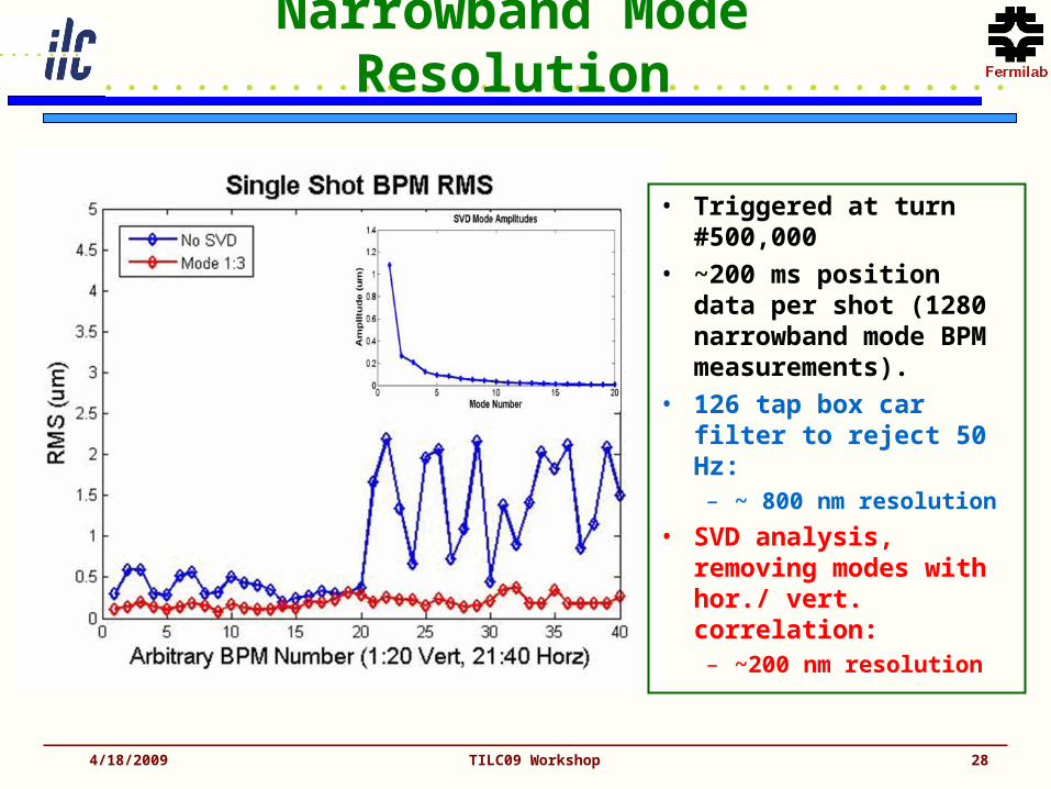
Narrowband Mode Resolution
4/18/2009 TILC09 Workshop 28
• Triggered at turn #500,000
• ~200 ms position data per shot (1280 narrowband mode BPM measurements).
• 126 tap box car filter to reject 50 Hz:– ~ 800 nm resolution
• SVD analysis, removing modes with hor./ vert. correlation:– ~200 nm resolution

Next Steps…
• “Final” Analog Downmixer with integrated CAL system– April 2009: perform beam tests on a pre-series (6 units)– Spring 2009: finalize layout– Summer 2009: production, test and burn-in of 110 units
• VME System– Spring 2009: finalize VME digitizer hardware– Summer 2009: establish downconverter & filter firmware– Fall 2009: Series production of 55 units– Fall 2009: Overhaul of the timing module(s), increase clock
frequency to 40 samples / turn, increase # of CLK outputs– Winter 2009: finalize timing modules.
• Software– Integration of VME digitizer (drivers, EPICS interface, etc.)
4/18/2009 TILC09 Workshop 29
Conclusions
• A DR BPM read-out system with high resolution in TBT (few µm), and narrowband mode (<200 nm) has been developed.
• An automatic calibration system for gain drift correction was tested. It operates in presence of the beam signal!– Systematic long term studies using the automatic gain correction
system need to be accomplished.
• Soft-/firmware activities & beam studies at ATF could be realized through remote operation!
• TBT kicked beam response studies uncovered discrepancies between theoretical and measured ATF DR optics.
• A revised analog/calibration electronics has been prototyped to resolve problems and limitations of the first series (20-of-96).– To be tested right now!
• Echotek digital receivers may be replaced by in-house developed VME digitizer modules for the digital signal processing.
4/18/2009 TILC09 Workshop 30
Backup
4/18/2009 TILC09 Workshop 31
Downconverter & CAL Proto
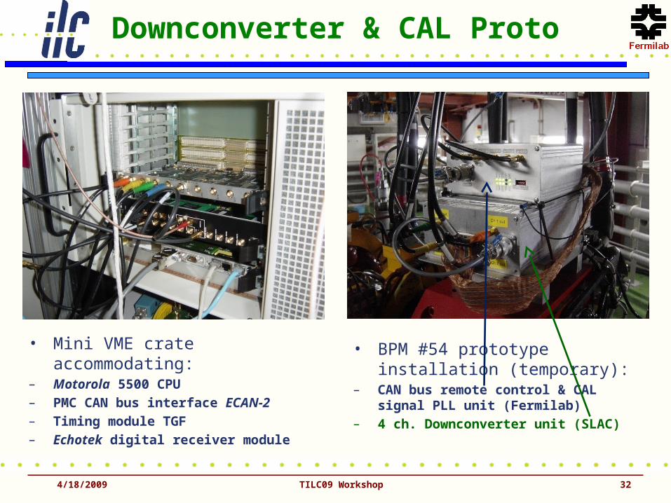
• Mini VME crate accommodating:– Motorola 5500 CPU– PMC CAN bus interface ECAN-2– Timing module TGF– Echotek digital receiver module
• BPM #54 prototype installation (temporary):
– CAN bus remote control & CAL signal PLL unit (Fermilab)
– 4 ch. Downconverter unit (SLAC)
4/18/2009 32TILC09 Workshop
EPICS Data Acquisition
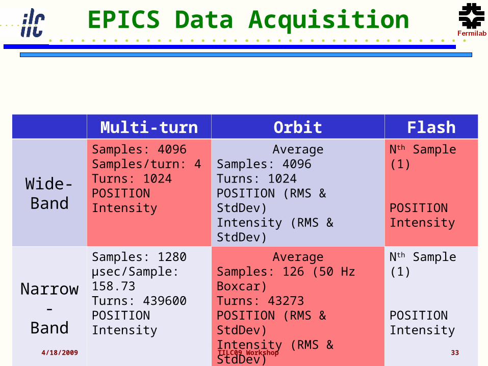
Multi-turn Orbit Flash
Wide-Band
Samples: 4096Samples/turn: 4Turns: 1024POSITIONIntensity
AverageSamples: 4096Turns: 1024POSITION (RMS & StdDev)Intensity (RMS & StdDev)
Nth Sample (1)
POSITIONIntensity
Narrow-Band
Samples: 1280µsec/Sample: 158.73Turns: 439600POSITIONIntensity
AverageSamples: 126 (50 Hz Boxcar)Turns: 43273POSITION (RMS & StdDev)Intensity (RMS & StdDev)
Nth Sample (1)
POSITIONIntensity
4/18/2009 TILC09 Workshop 33
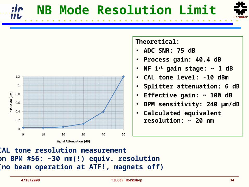
NB Mode Resolution Limit
4/18/2009 TILC09 Workshop 34
Theoretical:• ADC SNR: 75 dB• Process gain: 40.4 dB• NF 1st gain stage: ~ 1 dB• CAL tone level: -10 dBm• Splitter attenuation: 6 dB• Effective gain: ~ 100 dB• BPM sensitivity: 240 µm/dB• Calculated equivalent
resolution: ~ 20 nm
CAL tone resolution measurementon BPM #56: ~30 nm(!) equiv. resolution(no beam operation at ATF!, magnets off)