Embed Size (px)
Citation preview
This document and trademark(s) contained herein are protected by law as indicated in a notice appearing later in this work. This electronic representation of RAND intellectual property is provided for non-commercial use only. Unauthorized posting of RAND PDFs to a non-RAND Web site is prohibited. RAND PDFs are protected under copyright law. Permission is required from RAND to reproduce, or reuse in another form, any of our research documents for commercial use. For information on reprint and linking permissions, please see RAND Permissions.
Limited Electronic Distribution Rights
This PDF document was made available from www.rand.org as a public
service of the RAND Corporation.
6Jump down to document
THE ARTS
CHILD POLICY
CIVIL JUSTICE
EDUCATION
ENERGY AND ENVIRONMENT
HEALTH AND HEALTH CARE
INTERNATIONAL AFFAIRS
NATIONAL SECURITY
POPULATION AND AGING
PUBLIC SAFETY
SCIENCE AND TECHNOLOGY
SUBSTANCE ABUSE
TERRORISM AND HOMELAND SECURITY
TRANSPORTATION ANDINFRASTRUCTURE
WORKFORCE AND WORKPLACE
The RAND Corporation is a nonprofit research organization providing objective analysis and effective solutions that address the challenges facing the public and private sectors around the world.
Visit RAND at www.rand.org
Explore RAND Project AIR FORCE
View document details
For More Information
Purchase this document
Browse Books & Publications
Make a charitable contribution
Support RAND
This product is part of the RAND Corporation technical report series. Reports may
include research findings on a specific topic that is limited in scope; present discus-
sions of the methodology employed in research; provide literature reviews, survey
instruments, modeling exercises, guidelines for practitioners and research profes-
sionals, and supporting documentation; or deliver preliminary findings. All RAND
reports undergo rigorous peer review to ensure that they meet high standards for re-
search quality and objectivity.
Challenges and Issues with the Further Aging of U.S. Air Force AircraftPolicy Options for Effective Life-Cycle Management of Resources
Jean R. Gebman
Prepared for the United States Air Force
Approved for public release; distribution unlimited
PROJECT AIR FORCE
The RAND Corporation is a nonprofit research organization providing objective analysis and effective solutions that address the challenges facing the public and private sectors around the world. RAND’s publications do not necessarily ref lect the opinions of its research clients and sponsors.
R® is a registered trademark.
© Copyright 2009 RAND Corporation
Permission is given to duplicate this document for personal use only, as long as it is unaltered and complete. Copies may not be duplicated for commercial purposes. Unauthorized posting of R AND documents to a non-R AND Web site is prohibited. R AND documents are protected under copyright law. For information on reprint and linking permissions, please visit the RAND permissions page (http://www.rand.org/publications/ permissions.html).
Published 2009 by the RAND Corporation1776 Main Street, P.O. Box 2138, Santa Monica, CA 90407-2138
1200 South Hayes Street, Arlington, VA 22202-50504570 Fifth Avenue, Suite 600, Pittsburgh, PA 15213-2665
RAND URL: http://www.rand.orgTo order RAND documents or to obtain additional information, contact
Distribution Services: Telephone: (310) 451-7002; Fax: (310) 451-6915; Email: [email protected]
The research described in this report was sponsored by the United States Air Force under Contract FA7014-06-C-0001. Further information may be obtained from the Strategic Planning Division, Directorate of Plans, Hq USAF.
Library of Congress Cataloging-in-Publication Data
Gebman, J. R. Challenges and issues with the further aging of U.S. Air Force aircraft : policy options for effective life-cycle management of resources / Jean R. Gebman. p. cm. Includes bibliographical references. ISBN 978-0-8330-4518-8 (pbk. : alk. paper) 1. United States. Air Force—Equipment—History. 2. Airplanes, Military—United States—Maintenance and repair. 3. United States. Air Force—Planning. 4. Airplanes—Airworthiness. I. Title.
UG1243.G429 2009 358.4'183—dc22
2009003493
iii
Preface
Effective, life-cycle management of resources for sustaining a set of aircraft fleets requires timely resolution of the challenges and issues that arise when seeking the right mix of investments in existing fleets while acquiring replacement equipment. Because the operational aircraft to be sustained include older aircraft, which also must be maintained through their remaining ser-vice lives, developing and maintaining system integrity are critical objectives throughout each fleet’s life cycle—from acquisition through sustainment. For example, concepts for assuring durability and damage tolerance provide the foundation for the Air Force’s Aircraft Structural Integrity Program (ASIP), its related structural integrity programs for engines (ENSIP), and its functional systems integrity program (FSIP),1 all of which have important roles in ensuring the airworthiness of Air Force aircraft. ASIP, ENSIP, and FSIP provide a common framework for managing and engineering the conceptualization, development, production, operation, and sustainment of Air Force aircraft. Tailoring and implementing ASIP, ENSIP, FSIP tasks to best fit the life-cycle needs and circumstances of individual programs are areas that can be helped greatly by systems engineering.
This report was prepared for the 11th Joint DoD/NASA/FAA Conference on Aging Air-craft. It draws from the author’s previous work on aging aircraft, also sponsored by the U.S. Air Force. That continuing RAND Project AIR FORCE (PAF) effort, “Status and Risk Assess-ments for Aging Aircraft,” is sponsored by Lt Gen Raymond E. Johns, Jr., Deputy Chief of Staff for Strategic Plans and Programs, Headquarters U.S. Air Force (AF/A8). Prior work per-formed for a project on “Renewing the Force” was supported by then Vice Chief of Staff Gen T. Michael Moseley. The current report was conducted within the Aerospace Force Develop-ment Program2 of RAND Project AIR FORCE and should be of interest to those respon-sible for the development and refinement of policies to improve the life-cycle management of resources related to aircraft-aging processes.
Previous work on the integrity of aging aircraft includes
Jean Gebman, • Opportunities for Systems Engineering to Contribute to Durability and Damage Tolerance of Hybrid Structures for Airframes, Santa Monica, Calif.: RAND Cor-poration, TR-489-AF, 2008.
1 Other programs come into play during a weapon system’s acquisition phase: the Mechanical Equipment and Subsys-tem Integrity Program (MECSIP) and the Avionics/Electronics Integrity Program. Activities within these programs have migrated to the FSIP during the sustainment portion of the life cycle.2 Now known as the Force Modernization and Employment Program.

iv Challenges and Issues with the Further Aging of U.S. Air Force Aircraft
Yool Kim, Stephen Sheehy, and Darryl Lenhardt, • A Survey of Aircraft Structural-Life Management Programs in the U.S. Navy, the Canadian Forces, and the U.S. Air Force, Santa Monica, Calif.: RAND Corporation, MG-370-AF, 2006.
RAND Project AIR FORCE
RAND Project AIR FORCE (PAF), a division of the RAND Corporation, is the U.S. Air Force’s federally funded research and development center for studies and analyses. PAF pro-vides the Air Force with independent analyses of policy alternatives affecting the development, employment, combat readiness, and support of current and future aerospace forces. Research is conducted in four programs: Force Modernization and Employment; Manpower, Personnel, and Training; Resource Management; and Strategy and Doctrine.
Additional information about PAF is available on our Web site: http://www.rand.org/paf/
v
Contents
Preface . . . . . . . . . . . . . . . . . . . . . . . . . . . . . . . . . . . . . . . . . . . . . . . . . . . . . . . . . . . . . . . . . . . . . . . . . . . . . . . . . . . . . . . . . . . . . . . . . . . . . . . . . . . iiiFigures . . . . . . . . . . . . . . . . . . . . . . . . . . . . . . . . . . . . . . . . . . . . . . . . . . . . . . . . . . . . . . . . . . . . . . . . . . . . . . . . . . . . . . . . . . . . . . . . . . . . . . . . . . . ixTables . . . . . . . . . . . . . . . . . . . . . . . . . . . . . . . . . . . . . . . . . . . . . . . . . . . . . . . . . . . . . . . . . . . . . . . . . . . . . . . . . . . . . . . . . . . . . . . . . . . . . . . . . . . . xiSummary . . . . . . . . . . . . . . . . . . . . . . . . . . . . . . . . . . . . . . . . . . . . . . . . . . . . . . . . . . . . . . . . . . . . . . . . . . . . . . . . . . . . . . . . . . . . . . . . . . . . . . . xiiiAcknowledgments . . . . . . . . . . . . . . . . . . . . . . . . . . . . . . . . . . . . . . . . . . . . . . . . . . . . . . . . . . . . . . . . . . . . . . . . . . . . . . . . . . . . . . . . . . . . . xvAbbreviations . . . . . . . . . . . . . . . . . . . . . . . . . . . . . . . . . . . . . . . . . . . . . . . . . . . . . . . . . . . . . . . . . . . . . . . . . . . . . . . . . . . . . . . . . . . . . . . . . xvii
CHAPTER ONE
Introduction . . . . . . . . . . . . . . . . . . . . . . . . . . . . . . . . . . . . . . . . . . . . . . . . . . . . . . . . . . . . . . . . . . . . . . . . . . . . . . . . . . . . . . . . . . . . . . . . . . . . . 1Background . . . . . . . . . . . . . . . . . . . . . . . . . . . . . . . . . . . . . . . . . . . . . . . . . . . . . . . . . . . . . . . . . . . . . . . . . . . . . . . . . . . . . . . . . . . . . . . . . . . . . . . 2Report Organization . . . . . . . . . . . . . . . . . . . . . . . . . . . . . . . . . . . . . . . . . . . . . . . . . . . . . . . . . . . . . . . . . . . . . . . . . . . . . . . . . . . . . . . . . . . . . 3
CHAPTER TWO
Historical Developments Relevant to the Further Aging of U.S. Air Force Aircraft . . . . . . . . . . . . . . . 5The U.S. Army Period, 1907–1947 . . . . . . . . . . . . . . . . . . . . . . . . . . . . . . . . . . . . . . . . . . . . . . . . . . . . . . . . . . . . . . . . . . . . . . . . . . . . . 5
Technical Developments . . . . . . . . . . . . . . . . . . . . . . . . . . . . . . . . . . . . . . . . . . . . . . . . . . . . . . . . . . . . . . . . . . . . . . . . . . . . . . . . . . . . . . 5Institutional Developments . . . . . . . . . . . . . . . . . . . . . . . . . . . . . . . . . . . . . . . . . . . . . . . . . . . . . . . . . . . . . . . . . . . . . . . . . . . . . . . . . . . 7
The First 15-Year Period as the U.S. Air Force, 1948–1962 . . . . . . . . . . . . . . . . . . . . . . . . . . . . . . . . . . . . . . . . . . . . . . . . 10Technical Developments . . . . . . . . . . . . . . . . . . . . . . . . . . . . . . . . . . . . . . . . . . . . . . . . . . . . . . . . . . . . . . . . . . . . . . . . . . . . . . . . . . . . . 11Institutional Developments . . . . . . . . . . . . . . . . . . . . . . . . . . . . . . . . . . . . . . . . . . . . . . . . . . . . . . . . . . . . . . . . . . . . . . . . . . . . . . . . . . 12
The Second 15-Year Period, 1963–1977 . . . . . . . . . . . . . . . . . . . . . . . . . . . . . . . . . . . . . . . . . . . . . . . . . . . . . . . . . . . . . . . . . . . . . . 13Technical Developments . . . . . . . . . . . . . . . . . . . . . . . . . . . . . . . . . . . . . . . . . . . . . . . . . . . . . . . . . . . . . . . . . . . . . . . . . . . . . . . . . . . . . 13Institutional Developments . . . . . . . . . . . . . . . . . . . . . . . . . . . . . . . . . . . . . . . . . . . . . . . . . . . . . . . . . . . . . . . . . . . . . . . . . . . . . . . . . . 14
The Third 15-Year Period, 1978–1992 . . . . . . . . . . . . . . . . . . . . . . . . . . . . . . . . . . . . . . . . . . . . . . . . . . . . . . . . . . . . . . . . . . . . . . . . 16Technical Developments . . . . . . . . . . . . . . . . . . . . . . . . . . . . . . . . . . . . . . . . . . . . . . . . . . . . . . . . . . . . . . . . . . . . . . . . . . . . . . . . . . . . . 17Institutional Developments . . . . . . . . . . . . . . . . . . . . . . . . . . . . . . . . . . . . . . . . . . . . . . . . . . . . . . . . . . . . . . . . . . . . . . . . . . . . . . . . . . 18
The Fourth 15-Year Period, 1993–2007 . . . . . . . . . . . . . . . . . . . . . . . . . . . . . . . . . . . . . . . . . . . . . . . . . . . . . . . . . . . . . . . . . . . . . . 19Technical Developments . . . . . . . . . . . . . . . . . . . . . . . . . . . . . . . . . . . . . . . . . . . . . . . . . . . . . . . . . . . . . . . . . . . . . . . . . . . . . . . . . . . . 20Institutional Developments . . . . . . . . . . . . . . . . . . . . . . . . . . . . . . . . . . . . . . . . . . . . . . . . . . . . . . . . . . . . . . . . . . . . . . . . . . . . . . . . . 20
CHAPTER THREE
Technical Challenges for Operators of Aging Aircraft . . . . . . . . . . . . . . . . . . . . . . . . . . . . . . . . . . . . . . . . . . . . . . . 23Metal-Airframe Structure . . . . . . . . . . . . . . . . . . . . . . . . . . . . . . . . . . . . . . . . . . . . . . . . . . . . . . . . . . . . . . . . . . . . . . . . . . . . . . . . . . . . . 23
Single Fatigue Cracks . . . . . . . . . . . . . . . . . . . . . . . . . . . . . . . . . . . . . . . . . . . . . . . . . . . . . . . . . . . . . . . . . . . . . . . . . . . . . . . . . . . . . . . . 23Widespread Fatigue Damage . . . . . . . . . . . . . . . . . . . . . . . . . . . . . . . . . . . . . . . . . . . . . . . . . . . . . . . . . . . . . . . . . . . . . . . . . . . . . . . 24Generalized Fatigue Damage . . . . . . . . . . . . . . . . . . . . . . . . . . . . . . . . . . . . . . . . . . . . . . . . . . . . . . . . . . . . . . . . . . . . . . . . . . . . . . . . 25
vi Challenges and Issues with the Further Aging of U.S. Air Force Aircraft
Stress Corrosion Cracking . . . . . . . . . . . . . . . . . . . . . . . . . . . . . . . . . . . . . . . . . . . . . . . . . . . . . . . . . . . . . . . . . . . . . . . . . . . . . . . . . . . 25Exfoliation Corrosion . . . . . . . . . . . . . . . . . . . . . . . . . . . . . . . . . . . . . . . . . . . . . . . . . . . . . . . . . . . . . . . . . . . . . . . . . . . . . . . . . . . . . . . 27Crevice Corrosion . . . . . . . . . . . . . . . . . . . . . . . . . . . . . . . . . . . . . . . . . . . . . . . . . . . . . . . . . . . . . . . . . . . . . . . . . . . . . . . . . . . . . . . . . . . . 28
Composite-Airframe Structure . . . . . . . . . . . . . . . . . . . . . . . . . . . . . . . . . . . . . . . . . . . . . . . . . . . . . . . . . . . . . . . . . . . . . . . . . . . . . . . 30Honeycomb Structure . . . . . . . . . . . . . . . . . . . . . . . . . . . . . . . . . . . . . . . . . . . . . . . . . . . . . . . . . . . . . . . . . . . . . . . . . . . . . . . . . . . . . . . 30Carbon-Fiber Structure . . . . . . . . . . . . . . . . . . . . . . . . . . . . . . . . . . . . . . . . . . . . . . . . . . . . . . . . . . . . . . . . . . . . . . . . . . . . . . . . . . . . . . 31
Propulsion . . . . . . . . . . . . . . . . . . . . . . . . . . . . . . . . . . . . . . . . . . . . . . . . . . . . . . . . . . . . . . . . . . . . . . . . . . . . . . . . . . . . . . . . . . . . . . . . . . . . . . . . 32Material Deterioration . . . . . . . . . . . . . . . . . . . . . . . . . . . . . . . . . . . . . . . . . . . . . . . . . . . . . . . . . . . . . . . . . . . . . . . . . . . . . . . . . . . . . . . 32Technical Obsolescence . . . . . . . . . . . . . . . . . . . . . . . . . . . . . . . . . . . . . . . . . . . . . . . . . . . . . . . . . . . . . . . . . . . . . . . . . . . . . . . . . . . . . . 32
Systems . . . . . . . . . . . . . . . . . . . . . . . . . . . . . . . . . . . . . . . . . . . . . . . . . . . . . . . . . . . . . . . . . . . . . . . . . . . . . . . . . . . . . . . . . . . . . . . . . . . . . . . . . . . 32Material Deterioration . . . . . . . . . . . . . . . . . . . . . . . . . . . . . . . . . . . . . . . . . . . . . . . . . . . . . . . . . . . . . . . . . . . . . . . . . . . . . . . . . . . . . . . 33Technical Obsolescence . . . . . . . . . . . . . . . . . . . . . . . . . . . . . . . . . . . . . . . . . . . . . . . . . . . . . . . . . . . . . . . . . . . . . . . . . . . . . . . . . . . . . . 33
CHAPTER FOUR
Institutional Challenges for Operators of Aging Aircraft . . . . . . . . . . . . . . . . . . . . . . . . . . . . . . . . . . . . . . . . . . . . . 35Independent Verification of Fleet Status and Independent Forecasts of Future Conditions . . . . . . . . . . . 35
Equipment Manufacturers . . . . . . . . . . . . . . . . . . . . . . . . . . . . . . . . . . . . . . . . . . . . . . . . . . . . . . . . . . . . . . . . . . . . . . . . . . . . . . . . . . 36Sustainment Providers . . . . . . . . . . . . . . . . . . . . . . . . . . . . . . . . . . . . . . . . . . . . . . . . . . . . . . . . . . . . . . . . . . . . . . . . . . . . . . . . . . . . . . . 36Aircraft Operators . . . . . . . . . . . . . . . . . . . . . . . . . . . . . . . . . . . . . . . . . . . . . . . . . . . . . . . . . . . . . . . . . . . . . . . . . . . . . . . . . . . . . . . . . . . 36Airworthiness Authorities . . . . . . . . . . . . . . . . . . . . . . . . . . . . . . . . . . . . . . . . . . . . . . . . . . . . . . . . . . . . . . . . . . . . . . . . . . . . . . . . . . . 36Independent-Assessment Authorities for Airworthiness/Fleet Viability . . . . . . . . . . . . . . . . . . . . . . . . . . . . . . . 37
Limitations on Information for Analyses . . . . . . . . . . . . . . . . . . . . . . . . . . . . . . . . . . . . . . . . . . . . . . . . . . . . . . . . . . . . . . . . . . . . 38Structural Fatigue . . . . . . . . . . . . . . . . . . . . . . . . . . . . . . . . . . . . . . . . . . . . . . . . . . . . . . . . . . . . . . . . . . . . . . . . . . . . . . . . . . . . . . . . . . . . 38Corrosion . . . . . . . . . . . . . . . . . . . . . . . . . . . . . . . . . . . . . . . . . . . . . . . . . . . . . . . . . . . . . . . . . . . . . . . . . . . . . . . . . . . . . . . . . . . . . . . . . . . . . . 39Composite Structure . . . . . . . . . . . . . . . . . . . . . . . . . . . . . . . . . . . . . . . . . . . . . . . . . . . . . . . . . . . . . . . . . . . . . . . . . . . . . . . . . . . . . . . . . 40Propulsion. . . . . . . . . . . . . . . . . . . . . . . . . . . . . . . . . . . . . . . . . . . . . . . . . . . . . . . . . . . . . . . . . . . . . . . . . . . . . . . . . . . . . . . . . . . . . . . . . . . . . 40Systems . . . . . . . . . . . . . . . . . . . . . . . . . . . . . . . . . . . . . . . . . . . . . . . . . . . . . . . . . . . . . . . . . . . . . . . . . . . . . . . . . . . . . . . . . . . . . . . . . . . . . . . . 40
Scarcity of Resources . . . . . . . . . . . . . . . . . . . . . . . . . . . . . . . . . . . . . . . . . . . . . . . . . . . . . . . . . . . . . . . . . . . . . . . . . . . . . . . . . . . . . . . . . . 40
CHAPTER FIVE
Issues and Policy Options for Effective Life-Cycle Management . . . . . . . . . . . . . . . . . . . . . . . . . . . . . . . . . . . . 41Issues . . . . . . . . . . . . . . . . . . . . . . . . . . . . . . . . . . . . . . . . . . . . . . . . . . . . . . . . . . . . . . . . . . . . . . . . . . . . . . . . . . . . . . . . . . . . . . . . . . . . . . . . . . . . . . 41Policy for Developing Sustainment Master Plans . . . . . . . . . . . . . . . . . . . . . . . . . . . . . . . . . . . . . . . . . . . . . . . . . . . . . . . . . 42Policy for Coordinating Remaining-Life Investments . . . . . . . . . . . . . . . . . . . . . . . . . . . . . . . . . . . . . . . . . . . . . . . . . . . . . 43Policy for Establishing Service-Life Goals . . . . . . . . . . . . . . . . . . . . . . . . . . . . . . . . . . . . . . . . . . . . . . . . . . . . . . . . . . . . . . . . . . 43
CHAPTER SIX
Finding the Right Pathway for Implementing Preferred Policy Options . . . . . . . . . . . . . . . . . . . . . . . . . . . 45A Domain Model of the Resource-Management System . . . . . . . . . . . . . . . . . . . . . . . . . . . . . . . . . . . . . . . . . . . . . . . . . . 45
Principal Domains of the System . . . . . . . . . . . . . . . . . . . . . . . . . . . . . . . . . . . . . . . . . . . . . . . . . . . . . . . . . . . . . . . . . . . . . . . . . . . 45Interdependencies Among Domains . . . . . . . . . . . . . . . . . . . . . . . . . . . . . . . . . . . . . . . . . . . . . . . . . . . . . . . . . . . . . . . . . . . . . . . . 47Implementation of Preferred Policies Across Domains . . . . . . . . . . . . . . . . . . . . . . . . . . . . . . . . . . . . . . . . . . . . . . . . . . . 47Opportunities to Add Value . . . . . . . . . . . . . . . . . . . . . . . . . . . . . . . . . . . . . . . . . . . . . . . . . . . . . . . . . . . . . . . . . . . . . . . . . . . . . . . . . 47Observation of Value . . . . . . . . . . . . . . . . . . . . . . . . . . . . . . . . . . . . . . . . . . . . . . . . . . . . . . . . . . . . . . . . . . . . . . . . . . . . . . . . . . . . . . . . 48
Finding the Right Pathway for Enhancing the Resource-Management System . . . . . . . . . . . . . . . . . . . . . . . . . 49Testing and Evaluating a Prototype Pathway . . . . . . . . . . . . . . . . . . . . . . . . . . . . . . . . . . . . . . . . . . . . . . . . . . . . . . . . . . . . . . . 50
Contents vii
An Exploratory Prototype. . . . . . . . . . . . . . . . . . . . . . . . . . . . . . . . . . . . . . . . . . . . . . . . . . . . . . . . . . . . . . . . . . . . . . . . . . . . . . . . . . . 50A Test and Evaluation Plan . . . . . . . . . . . . . . . . . . . . . . . . . . . . . . . . . . . . . . . . . . . . . . . . . . . . . . . . . . . . . . . . . . . . . . . . . . . . . . . . . 50
CHAPTER SEVEN
Conclusions . . . . . . . . . . . . . . . . . . . . . . . . . . . . . . . . . . . . . . . . . . . . . . . . . . . . . . . . . . . . . . . . . . . . . . . . . . . . . . . . . . . . . . . . . . . . . . . . . . . . . 51
APPENDIX
Policy Options for Addressing Challenges and Issues . . . . . . . . . . . . . . . . . . . . . . . . . . . . . . . . . . . . . . . . . . . . . . . . . 53
Bibliography . . . . . . . . . . . . . . . . . . . . . . . . . . . . . . . . . . . . . . . . . . . . . . . . . . . . . . . . . . . . . . . . . . . . . . . . . . . . . . . . . . . . . . . . . . . . . . . . . . . . 59

ix
Figures
1.1. Challenges and Issues with the Further Aging of U.S. Air Force Aircraft . . . . . . . . . . . . . . . . . . . 2 2.1. Composition of Chemical Elements That Were Alloyed with Weak Aluminum
to Produce a Fairly Strong Aluminum Alloy 2024 . . . . . . . . . . . . . . . . . . . . . . . . . . . . . . . . . . . . . . . . . . . . . 7 2.2. Typical Systems Breakdown Structure for an Aircraft . . . . . . . . . . . . . . . . . . . . . . . . . . . . . . . . . . . . . . . . . 8 2.3. Institutional Breakdown Structure for Contractor Organizations Involved in the
Life-Cycle Management of Aging-Related Resources . . . . . . . . . . . . . . . . . . . . . . . . . . . . . . . . . . . . . . . . . . 9 2.4. Institutional Architecture for Government Organizations and Contractor
Maintenance Organizations Involved in the Life-Cycle Management of Aging-Related Resources . . . . . . . . . . . . . . . . . . . . . . . . . . . . . . . . . . . . . . . . . . . . . . . . . . . . . . . . . . . . . . . . . . . . . . . . . . 10
2.5. Composition of Chemical Elements That Were Alloyed with Aluminum to Produce Aluminum Alloy 7178 . . . . . . . . . . . . . . . . . . . . . . . . . . . . . . . . . . . . . . . . . . . . . . . . . . . . . . . . . . . . . . . . . . 11
2.6. F-111 Parts Fabricated from High-Strength D6ac Steel, Including the Wing’s Carry-Through Box . . . . . . . . . . . . . . . . . . . . . . . . . . . . . . . . . . . . . . . . . . . . . . . . . . . . . . . . . . . . . . . . . . . . . . . . . . . . . . . . 14
2.7. Manufacturing Defect (Bottom Picture) in the Wing Pivot Fitting (Top Picture) Fastened to the Wing’s Carry-Through Box in an F-111 That Led to an Accident in 1969 . . . . . . . . . . . . . . . . . . . . . . . . . . . . . . . . . . . . . . . . . . . . . . . . . . . . . . . . . . . . . . . . . . . . . . . . . . . . . . . . . . . . . . . . . . . . . . 15
2.8. Failed Horizontal Stabilizer from the 707-300 That Crashed in Africa During 1977 . . . . 16 2.9. U.S. Air Force Aircraft Losses Attributed to Structural Causes . . . . . . . . . . . . . . . . . . . . . . . . . . . . . . 17 2.10. Small Cracks Along the Lap Joint That Caused the 1988 Failure of the Aloha 737 . . . . . . . 18 2.11. Section of Fuselage That Failed in the 1988 Flight of the Aloha 737 . . . . . . . . . . . . . . . . . . . . . . . 19 3.1. Example of Stress Corrosion Cracking of a Forging Cut from a Fuselage Frame . . . . . . . . . 26 3.2. Example of Exfoliation Corrosion of Stiffeners That Were Removed from Inside the
Center Box of a Horizontal Stabilizer . . . . . . . . . . . . . . . . . . . . . . . . . . . . . . . . . . . . . . . . . . . . . . . . . . . . . . . . . . 28 3.3. Example of Exfoliation Corrosion Around a Steel Fastener in the Upper Surface
of a Wing . . . . . . . . . . . . . . . . . . . . . . . . . . . . . . . . . . . . . . . . . . . . . . . . . . . . . . . . . . . . . . . . . . . . . . . . . . . . . . . . . . . . . . . . . . . 29 3.4. Crevice Corrosion on a Pair of Doublers That Were Spot-Welded and Fastened to a
Fuselage Skin to Provide Reinforcement . . . . . . . . . . . . . . . . . . . . . . . . . . . . . . . . . . . . . . . . . . . . . . . . . . . . . . . 30 3.5. Example of What Probably Started as Crevice Corrosion and Progressed to an
Exfoliation Corrosion That Consumed the Full Thickness of Some Sheets of Material . . . . . . . . . . . . . . . . . . . . . . . . . . . . . . . . . . . . . . . . . . . . . . . . . . . . . . . . . . . . . . . . . . . . . . . . . . . . . . . . . . . . . . . . . . . . . 31
6.1. Decomposition of the Resource Management System into a Set of Six Domains . . . . . . . . 46

xi
Tables
2.1. Periods in the Development and Evolution of the U.S. Air Force . . . . . . . . . . . . . . . . . . . . . . . . . . . . 6 2.2. Common Process Issues and Effects for ASIP Engineering, 2004–2006 . . . . . . . . . . . . . . . . . . 22 2.3. Common Process Issues and Effects for ASIP Management, 2004–2006 . . . . . . . . . . . . . . . . . 22

xiii
Summary
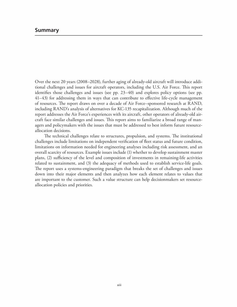
Over the next 20 years (2008–2028), further aging of already-old aircraft will introduce addi-tional challenges and issues for aircraft operators, including the U.S. Air Force. This report identifies those challenges and issues (see pp. 23–40) and explores policy options (see pp. 41–43) for addressing them in ways that can contribute to effective life-cycle management of resources. The report draws on over a decade of Air Force–sponsored research at RAND, including RAND’s analysis of alternatives for KC-135 recapitalization. Although much of the report addresses the Air Force’s experiences with its aircraft, other operators of already-old air-craft face similar challenges and issues. This report aims to familiarize a broad range of man-agers and policymakers with the issues that must be addressed to best inform future resource-allocation decisions.
The technical challenges relate to structures, propulsion, and systems. The institutional challenges include limitations on independent verification of fleet status and future condition, limitations on information needed for engineering analyses including risk assessment, and an overall scarcity of resources. Example issues include (1) whether to develop sustainment master plans, (2) sufficiency of the level and composition of investments in remaining-life activities related to sustainment, and (3) the adequacy of methods used to establish service-life goals. The report uses a systems-engineering paradigm that breaks the set of challenges and issues down into their major elements and then analyzes how each element relates to values that are important to the customer. Such a value structure can help decisionmakers set resource- allocation policies and priorities.

xv
Acknowledgments
In the process of writing this report, the author benefited from informal reviews and ideas from many colleagues at RAND, including Natalie Crawford, Yool Kim, and William Stanley. Joseph P. Gallagher and Anthony Rosello provided formal reviews.
The author further acknowledges the importance of past work on many projects related to the acquisition and sustainment of weapon systems. Associations with many colleagues at RAND and in the U.S. Air Force over the years contributed to shaping a context within which the present report was written.

xvii
Abbreviations
AD airworthiness directiveAF/A8 Deputy Chief of Staff for Strategic Plans and Programs, Headquarters
United States Air ForceAFI Air Force InstructionAFMC/ASC Air Force Materiel Command, Aeronautical Systems CenterAFPD Air Force Policy DirectiveASC/EN Aeronautical Systems Center, Engineering DirectorateASIP Aircraft Structural Integrity ProgramAVIP Avionics/Electronics Integrity ProgramCCP coherent, comprehensive planCVA corrosion vulnerable areasDoD Department of DefenseENSIP Engine Structural Integrity ProgramFAA Federal Aviation AdministrationFCL fatigue critical locationFSIP Functional Systems Integrity ProgramFSMP force structural maintenance planFVB Fleet Viability BoardGFD generalized fatigue damageGFE government furnished equipmentIAT Individual Aircraft Tracking programICD interface control documentIEEE Institute of Electrical and Electronics EngineersIR&D internal research and developmentL/ESS Loads/Environment Spectra SurveyMECSIP Mechanical Equipment and Subsystem Integrity ProgramMIL-STD military standardMRO maintenance, repair and overhaulNASA National Aeronautics and Space AdministrationNRC National Research Council
xviii Challenges and Issues with the Further Aging of U.S. Air Force Aircraft
NTSB National Transportation Safety BoardOMB Office of Management and BudgetOSD Office of the Secretary of DefensePAF RAND Project AIR FORCER&D research and developmentSAC Strategic Air CommandSAF/AQ Assistant Secretary of the Air Force for Acquisition, Headquarters United
States Air Force SCC stress corrosion crackingSMP Sustainment master plan or planningUSAF United States Air ForceWFD widespread fatigue damage
1
CHAPTER ONE
Introduction
This report discusses aircraft-related technical and institutional challenges and other relevant issues that the U.S. Air Force must address as it sustains already-old military aircraft over the next 20 years and possibly beyond. Owner-operators of such aircraft need to develop and implement (1) an effective way to select the service-life goal of an existing old aircraft weapon system and (2) a well-thought-out approach for cost-effectively investing in the sustainment of such aircraft through their remaining years, while phasing in a replacement for those aircraft capabilities that need to be continued beyond the current aircraft’s remaining life. Such an action-based policy change is especially important for aircraft fleets that already have shown signs of advanced structural-aging damage.1
As already-old aircraft experience further aging,2 exacerbating the formidable challenges and issues already facing the U.S. Air Force, the prospective policies and actions described in this report will assist resource managers whose decisions will determine the effectiveness of the Air Force’s life-cycle management of resources3 for its fleets of aging aircraft.4
Over the next 20 years (2008–2028), further aging of already-old aircraft will introduce additional challenges and issues (Figure 1.1) especially for the U.S. Air Force, because it is one of the world’s largest operators of old aircraft. Other operators of such aircraft also can expect to face many of the same challenges and issues. To help these operators’ efforts, this report provides aircraft managers with tools to better inform their resource-allocation decisions; and it highlights policy options that senior decisionmakers might find useful to consider to clarify
1 The word aging is used in the aircraft-sustainment sector of the aviation industry to characterize processes and equipment that evidence rising needs for inspections, maintenance, and modifications as aircraft are operated for periods of time well beyond the usual break-in period where design glitches are addressed during early production and operation.2 The term further aging is used in this report to make a distinction between what is commonly accepted as aging, as now observed in current fleets of aircraft, and further significant extensions of life being contemplated by aircraft operators, including the U.S. Air Force. For example, from an engineering perspective, it is reasonable to expect that the aging chal-lenges facing 75-year-old KC-135s will be far more severe than those now facing 45-year-old KC-135s.3 For military equipment, it is common practice for the term life-cycle management of resources to refer the management of all equipment-related resources that are used from the start of the equipment’s life (concept formulation) through its final disposal (at the end of life). Commonly considered classes of resources include labor, material, facilities, equipment, and purchased services.4 The term aging aircraft has become a widely used descriptor for those aircraft that already have served a substantial por-tion of the designers’ intended life and are entering a period where the burden of continued use will likely rise over time to comply with airworthiness expectations.

2 Challenges and Issues with the Further Aging of U.S. Air Force Aircraft
Figure 1.1 Challenges and Issues with the Further Aging of U.S. Air Force Aircraft
RAND TR560-1.1
Sustainment master plans?Investments in sustainment activities?Establishment of service-life goals?
Independent verification
Limited information
Scarcity of resources
Material deterioration
Obsolesence
Technical challenges Institutional challenges
Issues
expectations and provide guidance to both aircraft managers and the resource managers on which aircraft managers must depend.5
Although the immediate problems facing the U.S. Air Force are with the sustainment and retirement of its aging aircraft, the policy options considered here would apply to all U.S. Air Force aircraft. This broad applicability is a consequence of the fact that effective preparation for quality service during a fleet’s golden years is a function of how the fleet is used, managed, and sustained throughout its service life.
Background
Current sustainment approaches for older aircraft are a concern because their airframe sus-tainment processes are not based on a clear understanding of the current structural health of the airframe. Generally, it appears that operators use a reactive approach to address each new aging/damage-related problem, going into almost a crisis mode that considers each problem as an isolated event. The evolution of the current approach for airframes has been driven by three factors: (1) budgets that reduced sustainment resources, especially for engineering sup-port of long-term decisions, (2) overwhelming numbers of older aircraft that continuously need additional capability to meet evolving threats and satisfy new mission requirements, and (3)
5 For the U.S. Air Force, the term aircraft manager refers to a fleet’s system program manager. For civil aviation, the term refers to the original equipment manufacturer during the development phase and to the airline’s person in charge of logistics during the sustainment phase.
Introduction 3
policy changes that de-emphasized adherence to integrity principles and system-engineering processes.
The reactive mode of sustaining aircraft has affected availability and mission readiness and has also led to increasing overall maintenance costs. Hasty decisions have resulted in stop-gap solutions that treat symptoms rather than address underlying problems. For example, by not evaluating the cause and extent of the extensive fatigue damage being observed in the thin center wing that was used for one fleet of aircraft, decisionmakers chose a short-term solution that placed steel straps on the lower-wing surface to reduce stresses causing local cracking.
By adding straps to center wings, not knowing that they were already cracked (and basi-cally worn out), decisionmakers ultimately produced an interim, ineffective solution for sus-taining the fleet’s capability until the later part of the 2020s. No serious thinking was given to the underlining aging issues nor was a proactive effort initiated to develop a terminal solution to this generalized cracking problem in the wing. By about 2005, it finally was realized that the cure for this aging problem was a program to replace the center wing; this is now under way.6
The foregoing example illustrates how knee-jerk reactions to the discovery of significant aging damage can result in solutions that adversely affect the availability and sustainment costs of critically important aircraft weapon systems. A solution to this type of chaos is to have a sus-tainment master plan founded on an awareness of the aging damage occurring in each aircraft in a fleet and to plan for fleet-wide actions well before any actions need to be taken (seven to ten years).
As the F-15C mishap of November 2, 2007, illustrates, catastrophic structural failures are possible. In this mishap (involving aircraft serial number 80-0034), the failure occurred at a location where F-15 aircraft had never previously been known to develop cracking. Attention is always given to known problems and to their mitigation, not to areas that are judged to be problem-free. In the unlikely event that manufacturing quality control for older fleets could allow major deviations from blueprint requirements, then a mishap such as that of the F-15C could occur. Such a situation, although rare, could cause local stresses to be so high that the structure would crack in service without warning and could possibly be the sole cause of a catastrophic mishap.
Report Organization
Chapters Two and Three summarize situations where aging damage has resulted in the loss of aircraft from catastrophic airframe failures. Although fear of such failures has increased the attention given to improving sustainment practices, sustainment master plans have yet to be developed for most aircraft weapon systems. Consequently, importance guidance may be missing for addressing maintenance requirements for the aging processes that will affect future aircraft performance.
Chapter Two focuses on the historical technical and institutional challenges that will dominate the further aging of already-old aircraft. Chapter Three describes the technical chal-lenges for operators of aircraft being affected by aging processes. Chapter Four addresses insti-
6 To prevent similar situations from arising, the U.S. Air Force modified MIL-STD-1530C to include a Task V (force management) practice to collect, analyze, store, and use the kinds of aging-damage information that could have been used to make the right decision the first time.
4 Challenges and Issues with the Further Aging of U.S. Air Force Aircraft
tutional challenges including limitations on independent verification of fleet status and future condition, limitations on information needed for engineering analyses including risk assess-ments, and an overall scarcity of resources. Chapter Four also identifies actions that the Air Force might take, including in-depth independent engineering evaluations of critical technical issues and overall aircraft weapon system evaluations such as those now being provided by the U.S. Air Force’s Fleet Viability Board (FVB).7
Chapter Five identifies issues arising from technical and institutional challenges. These include whether to develop sustainment master plans, the sufficiency of the level and compo-sition of investments in remaining-life activities related to sustainment, and the adequacy of methods used to establish service-life goals. Chapter Five also identifies a set of policy actions that the U.S. Air Force might consider to support a long-term fleet-by-fleet sustainment strat-egy. Chapter Six describes a systems approach to the development and evaluation of sets of policies for resolving issues.8 Chapter Seven provides conclusions.
7 The FVB assessments evaluate current and future ability to support technical functions and mission requirements. They also evaluate aircraft weapon system capability for meeting mission requirements for projected periods of 6, 14, and 25 years into the future.8 The naval nuclear propulsion program is an example of a program that invested in a very strong set of systems-engineer-ing practices, because failure was not an option; see Francis Duncan, Rickover and the Nuclear Navy, The Discipline of Tech-nology, Annapolis, Md.: Naval Institute Press, 1990; Theodore Rockwell, The Rickover Effect, How One Man Made a Dif-ference, Annapolis, Md.: Naval Institute Press, 1992; and Hyman Rickover, Admiral, U.S. Navy, Director, Naval Nuclear Propulsion Program, statement before the House Subcommittee on Energy and Propulsion, Washington, D.C., May 1979. The ballistic-missile programs and the continental air defense program also evidenced a strong application of systems-engi-neering practices; see Harvey M. Sapolsky, The Polaris System Development, Cambridge, Mass.: Harvard University Press, 1972; Edmund Beard, Developing the ICBM, New York: Columbia University Press, 1976; and Claude Baum, The System Builders: The Story of SDC, Santa Monica, Calif.: System Development Corporation, 1981. Early textbooks on systems engineering focused more on the mathematics than on the strong methods of technical direction that the cited programs employed; see, for example, William A. Porter, Modern Foundation of System Engineering, New York: Macmillan, 1968; Andrew P. Sage and James A. Melsa, System Identification, New York: Academic Press, 1971; and Andrew P. Sage, Systems Engineering: Methodology and Applications, New York: IEEE Press, 1977. Contemporary texts focus more on methods of technical architectures, organization of technical efforts, and technical direction; see, for example, Benjamin S. Blanchard and Wolter J. Fabrycky, Systems Engineering and Analysis, Upper Saddle River, N.J.: Prentice Hall, 1998; Dennis M. Buede, The Engineering Design of Systems, Models and Methods, New York: Wiley, 2000; and Mark W. Maier and Eberhardt Rechtin, The Art of Systems Architecting, Washington, D.C.: CRC Press, 2000. Handbooks for systems-engineering practices have been developed by the Department of Defense (DoD) (Defense Systems Management College, Systems Engineering Fun-damentals, Fort Belvoir, Va.: Defense Acquisition University Press, January 2001); the U.S. Air Force (Air Force Space and Missile Systems Center, Systems Engineering Primer and Handbook: Concepts, Processes, and Techniques, El Segundo, Calif.: Los Angeles Air Force Base, 2004); the National Aeronautics and Space Administration, Systems Engineering Handbook, SP-610S, Washington, D.C., June 1995; the Institute of Electrical and Electronics Engineers, Standard for Application and Management of the System Engineering Process, IEEE Standard 1220-1998, New York, 1998; the Government Electronics and Information Technology Association (GEITA), Processes for Engineering a System, ANSI/GEIA EIA-632, September 2003; and the International Council of Systems Engineers, Systems Engineering Handbook, Seattle, Wash., July 2000.
5
CHAPTER TWO
Historical Developments Relevant to the Further Aging of U.S. Air Force Aircraft
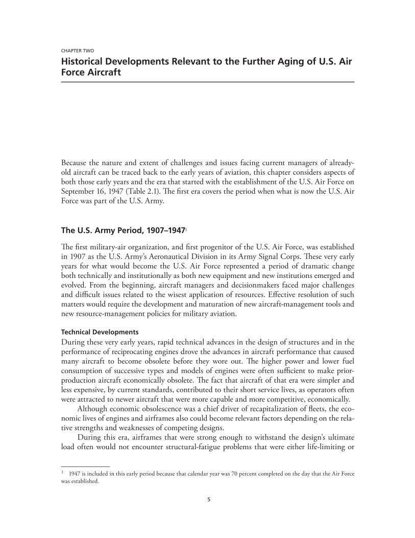
Because the nature and extent of challenges and issues facing current managers of already-old aircraft can be traced back to the early years of aviation, this chapter considers aspects of both those early years and the era that started with the establishment of the U.S. Air Force on September 16, 1947 (Table 2.1). The first era covers the period when what is now the U.S. Air Force was part of the U.S. Army.
The U.S. Army Period, 1907–19471
The first military-air organization, and first progenitor of the U.S. Air Force, was established in 1907 as the U.S. Army’s Aeronautical Division in its Army Signal Corps. These very early years for what would become the U.S. Air Force represented a period of dramatic change both technically and institutionally as both new equipment and new institutions emerged and evolved. From the beginning, aircraft managers and decisionmakers faced major challenges and difficult issues related to the wisest application of resources. Effective resolution of such matters would require the development and maturation of new aircraft-management tools and new resource-management policies for military aviation.
Technical Developments
During these very early years, rapid technical advances in the design of structures and in the performance of reciprocating engines drove the advances in aircraft performance that caused many aircraft to become obsolete before they wore out. The higher power and lower fuel consumption of successive types and models of engines were often sufficient to make prior- production aircraft economically obsolete. The fact that aircraft of that era were simpler and less expensive, by current standards, contributed to their short service lives, as operators often were attracted to newer aircraft that were more capable and more competitive, economically.
Although economic obsolescence was a chief driver of recapitalization of fleets, the eco-nomic lives of engines and airframes also could become relevant factors depending on the rela-tive strengths and weaknesses of competing designs.
During this era, airframes that were strong enough to withstand the design’s ultimate load often would not encounter structural-fatigue problems that were either life-limiting or
1 1947 is included in this early period because that calendar year was 70 percent completed on the day that the Air Force was established.
6 Challenges and Issues with the Further Aging of U.S. Air Force Aircraft
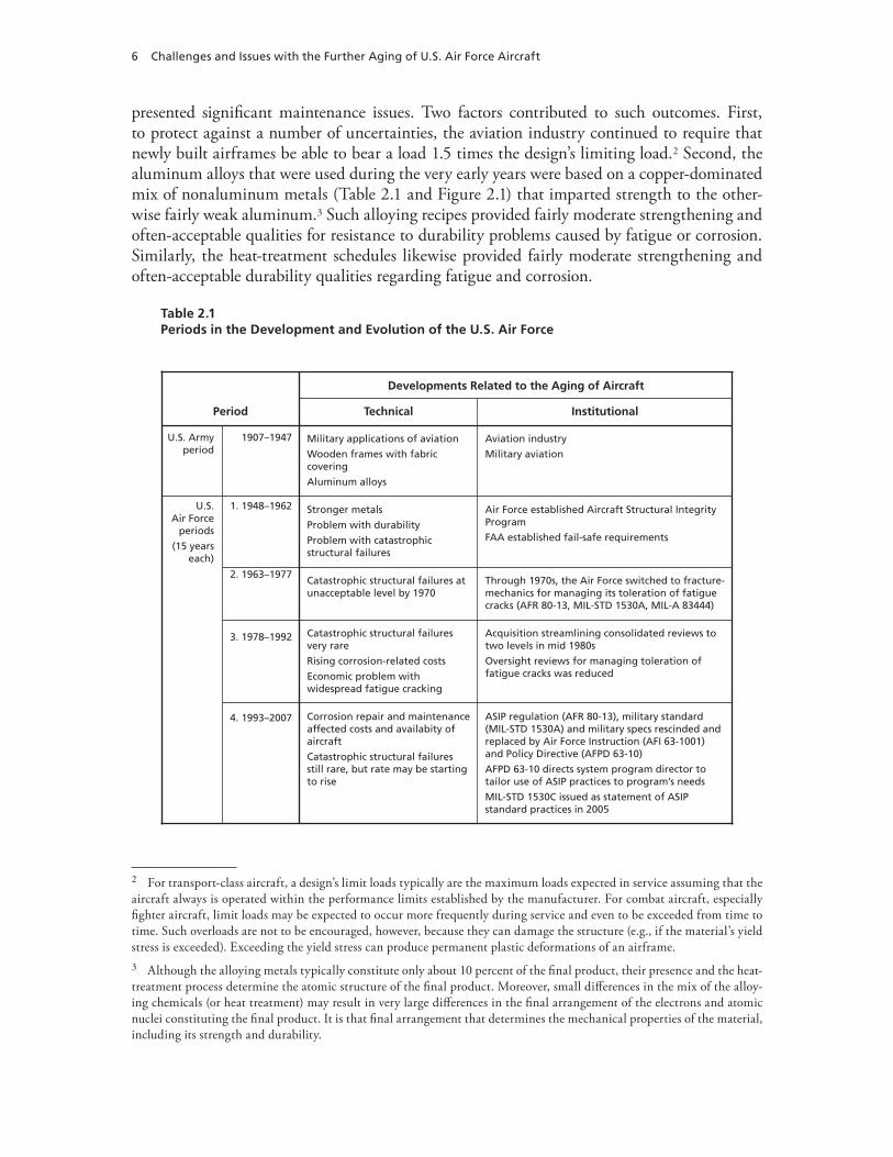
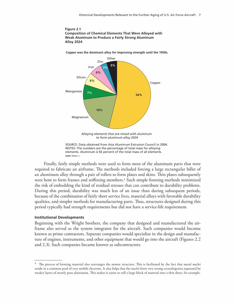
presented significant maintenance issues. Two factors contributed to such outcomes. First, to protect against a number of uncertainties, the aviation industry continued to require that newly built airframes be able to bear a load 1.5 times the design’s limiting load.2 Second, the aluminum alloys that were used during the very early years were based on a copper-dominated mix of nonaluminum metals (Table 2.1 and Figure 2.1) that imparted strength to the other-wise fairly weak aluminum.3 Such alloying recipes provided fairly moderate strengthening and often-acceptable qualities for resistance to durability problems caused by fatigue or corrosion.Similarly, the heat-treatment schedules likewise provided fairly moderate strengthening and often-acceptable durability qualities regarding fatigue and corrosion.
Table 2.1Periods in the Development and Evolution of the U.S. Air Force
Developments Related to the Aging of Aircraft
Technical Institutional
U.S.Air Force
periods
(15 yearseach)
Period
U.S. Armyperiod
1. 1948–1962
2. 1963–1977
3. 1978–1992
4. 1993–2007
1907–1947
Through 1970s, the Air Force switched to fracture-mechanics for managing its toleration of fatiguecracks (AFR 80-13, MIL-STD 1530A, MIL-A 83444)
Catastrophic structural failures atunacceptable level by 1970
Aviation industry
Military aviation
Military applications of aviation
Wooden frames with fabriccovering
Aluminum alloys
Air Force established Aircraft Structural IntegrityProgram
FAA established fail-safe requirements
Stronger metals
Problem with durability
Problem with catastrophicstructural failures
Acquisition streamlining consolidated reviews totwo levels in mid 1980s
Oversight reviews for managing toleration offatigue cracks was reduced
Catastrophic structural failuresvery rare
Rising corrosion-related costs
Economic problem withwidespread fatigue cracking
ASIP regulation (AFR 80-13), military standard(MIL-STD 1530A) and military specs rescinded andreplaced by Air Force Instruction (AFI 63-1001)and Policy Directive (AFPD 63-10)
AFPD 63-10 directs system program director totailor use of ASIP practices to program’s needs
MIL-STD 1530C issued as statement of ASIPstandard practices in 2005
Corrosion repair and maintenanceaffected costs and availabity ofaircraft
Catastrophic structural failuresstill rare, but rate may be startingto rise
2 For transport-class aircraft, a design’s limit loads typically are the maximum loads expected in service assuming that the aircraft always is operated within the performance limits established by the manufacturer. For combat aircraft, especially fighter aircraft, limit loads may be expected to occur more frequently during service and even to be exceeded from time to time. Such overloads are not to be encouraged, however, because they can damage the structure (e.g., if the material’s yield stress is exceeded). Exceeding the yield stress can produce permanent plastic deformations of an airframe.3 Although the alloying metals typically constitute only about 10 percent of the final product, their presence and the heat-treatment process determine the atomic structure of the final product. Moreover, small differences in the mix of the alloy-ing chemicals (or heat treatment) may result in very large differences in the final arrangement of the electrons and atomic nuclei constituting the final product. It is that final arrangement that determines the mechanical properties of the material, including its strength and durability.
Historical Developments Relevant to the Further Aging of U.S. Air Force Aircraft 7
Figure 2.1Composition of Chemical Elements That Were Alloyed with Weak Aluminum to Produce a Fairly Strong Aluminum Alloy 2024
54%
19%
7%
6%
6%
3%5%
SOURCE: Data obtained from Asia Aluminum Extrusion Council in 2004.NOTES: The numbers are the percentage of total mass for alloyingelements. Aluminum is 92 percent of the total mass of all elements.RAND TR560-2.1
Copper
Magnesium
Manganese
Silicon
Iron
ZincOther
Copper was the dominant alloy for improving strength until the 1950s.
Alloying elements that are mixed with aluminum to form aluminum alloy 2024
Finally, fairly simple methods were used to form most of the aluminum parts that were required to fabricate an airframe. The methods included forcing a large rectangular billet of an aluminum alloy through a pair of rollers to form plates and skins. Thin plates subsequently were bent to form frames and stiffening members.4 Such simple forming methods minimized the risk of embedding the kind of residual stresses that can contribute to durability problems. During this period, durability was much less of an issue than during subsequent periods, because of the combination of fairly short service lives, material alloys with favorable durability qualities, and simpler methods for manufacturing parts. Thus, structures designed during this period typically had strength requirements but did not have a service-life requirement.
Institutional Developments
Beginning with the Wright brothers, the company that designed and manufactured the air-frame also served as the system integrator for the aircraft. Such companies would become known as prime contractors. Separate companies would specialize in the design and manufac-ture of engines, instruments, and other equipment that would go into the aircraft (Figures 2.2 and 2.3). Such companies became known as subcontractors.
4 The process of forming material also rearranges the atomic structure. This is facilitated by the fact that metal nuclei reside in a common pool of very mobile electrons. It also helps that the nuclei form very strong crystals/grains separated by weaker layers of mostly pure aluminum. This makes it easier to roll a large block of material into a thin sheet, for example.
8 Challenges and Issues with the Further Aging of U.S. Air Force Aircraft
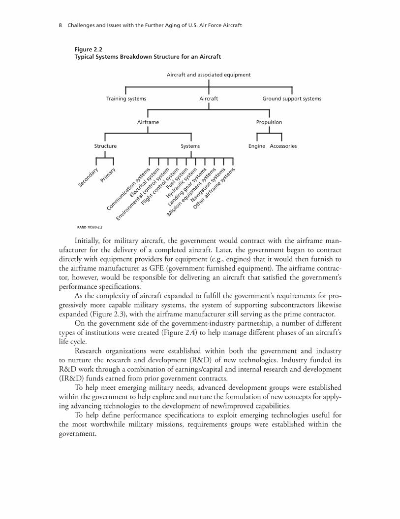
Figure 2.2Typical Systems Breakdown Structure for an Aircraft
RAND TR560-2.2
Engine Accessories
Landin
g gea
r sys
tem
s
Fuel
syste
m
Envir
onmen
tal c
ontrol s
yste
m
Electr
ical s
yste
m
Hydra
ulic sy
stem
Flight c
ontrol s
yste
m
Other
airfr
ame s
yste
ms
Navig
atio
n syste
ms
Comm
unicatio
n syste
ms
Miss
ion eq
uipm
ent s
yste
ms
Aircraft and associated equipment
Aircraft
Airframe
Systems
Propulsion
Training systems Ground support systems
Structure
Prim
ary
Seco
ndary
Initially, for military aircraft, the government would contract with the airframe man-ufacturer for the delivery of a completed aircraft. Later, the government began to contract directly with equipment providers for equipment (e.g., engines) that it would then furnish to the airframe manufacturer as GFE (government furnished equipment). The airframe contrac-tor, however, would be responsible for delivering an aircraft that satisfied the government’s performance specifications.
As the complexity of aircraft expanded to fulfill the government’s requirements for pro-gressively more capable military systems, the system of supporting subcontractors likewise expanded (Figure 2.3), with the airframe manufacturer still serving as the prime contractor.
On the government side of the government-industry partnership, a number of different types of institutions were created (Figure 2.4) to help manage different phases of an aircraft’s life cycle.
Research organizations were established within both the government and industry to nurture the research and development (R&D) of new technologies. Industry funded its R&D work through a combination of earnings/capital and internal research and development (IR&D) funds earned from prior government contracts.
To help meet emerging military needs, advanced development groups were established within the government to help explore and nurture the formulation of new concepts for apply-ing advancing technologies to the development of new/improved capabilities.
To help define performance specifications to exploit emerging technologies useful for the most worthwhile military missions, requirements groups were established within the government.
Historical Developments Relevant to the Further Aging of U.S. Air Force Aircraft 9
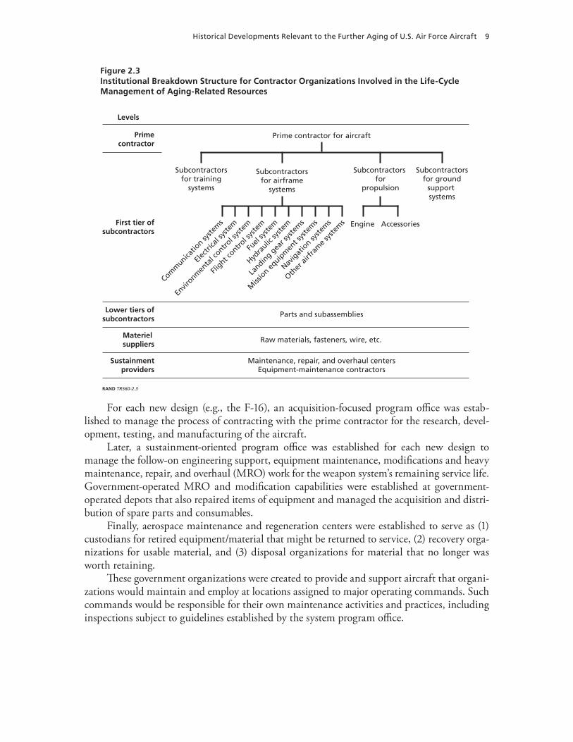
Figure 2.3Institutional Breakdown Structure for Contractor Organizations Involved in the Life-Cycle Management of Aging-Related Resources
RAND TR560-2.3
Prime contractor for aircraft
Subcontractorsfor training
systems
Subcontractorsfor ground
support systems
Engine Accessories
Subcontractors for
propulsion
Subcontractorsfor airframe
systems
Landin
g gea
r sys
tem
s
Fuel
syste
m
Envir
onmen
tal c
ontrol s
yste
m
Electr
ical s
yste
m
Hydra
ulic sy
stem
Flight c
ontrol s
yste
m
Other
airfr
ame s
yste
ms
Navig
atio
n syste
ms
Comm
unicatio
n syste
ms
Miss
ion eq
uipm
ent s
yste
ms
Levels
Primecontractor
First tier ofsubcontractors
Lower tiers ofsubcontractors
Materiel suppliers
Sustainmentproviders
Parts and subassemblies
Raw materials, fasteners, wire, etc.
Maintenance, repair, and overhaul centersEquipment-maintenance contractors
For each new design (e.g., the F-16), an acquisition-focused program office was estab-lished to manage the process of contracting with the prime contractor for the research, devel-opment, testing, and manufacturing of the aircraft.
Later, a sustainment-oriented program office was established for each new design to manage the follow-on engineering support, equipment maintenance, modifications and heavy maintenance, repair, and overhaul (MRO) work for the weapon system’s remaining service life. Government-operated MRO and modification capabilities were established at government-operated depots that also repaired items of equipment and managed the acquisition and distri-bution of spare parts and consumables.
Finally, aerospace maintenance and regeneration centers were established to serve as (1) custodians for retired equipment/material that might be returned to service, (2) recovery orga-nizations for usable material, and (3) disposal organizations for material that no longer was worth retaining.
These government organizations were created to provide and support aircraft that organi-zations would maintain and employ at locations assigned to major operating commands. Such commands would be responsible for their own maintenance activities and practices, including inspections subject to guidelines established by the system program office.
10 Challenges and Issues with the Further Aging of U.S. Air Force Aircraft
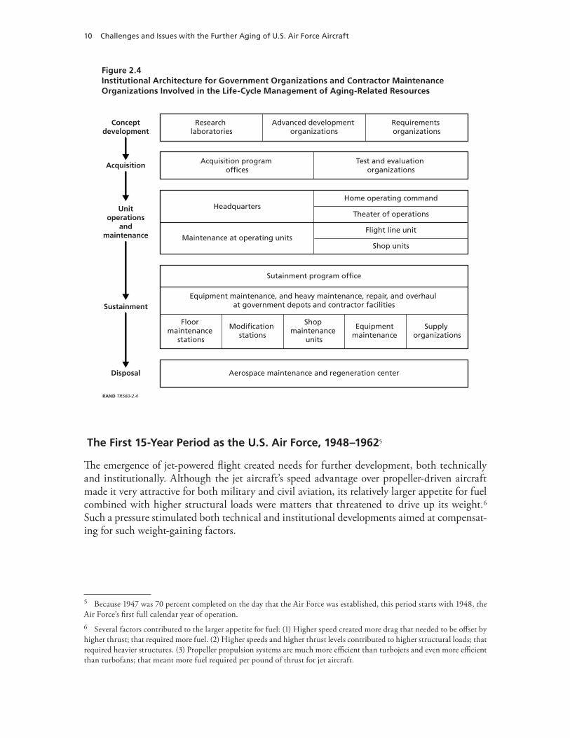
Figure 2.4Institutional Architecture for Government Organizations and Contractor Maintenance Organizations Involved in the Life-Cycle Management of Aging-Related Resources
RAND TR560-2.4
Conceptdevelopment
Acquisition
Unitoperations
andmaintenance
Sustainment
Disposal
Research laboratories
Advanced development organizations
Requirements organizations
Acquisition program offices
Test and evaluation organizations
Aerospace maintenance and regeneration center
Maintenance at operating unitsFlight line unit
Shop units
HeadquartersTheater of operations
Home operating command
Sutainment program office
Equipment maintenance, and heavy maintenance, repair, and overhaul at government depots and contractor facilities
Equipment maintenance
Floor maintenance
stations
Shop maintenance
units
Modification stations
Supply organizations
The First 15-Year Period as the U.S. Air Force, 1948–19625
The emergence of jet-powered flight created needs for further development, both technically and institutionally. Although the jet aircraft’s speed advantage over propeller-driven aircraft made it very attractive for both military and civil aviation, its relatively larger appetite for fuel combined with higher structural loads were matters that threatened to drive up its weight.6 Such a pressure stimulated both technical and institutional developments aimed at compensat-ing for such weight-gaining factors.
5 Because 1947 was 70 percent completed on the day that the Air Force was established, this period starts with 1948, the Air Force’s first full calendar year of operation.6 Several factors contributed to the larger appetite for fuel: (1) Higher speed created more drag that needed to be offset by higher thrust; that required more fuel. (2) Higher speeds and higher thrust levels contributed to higher structural loads; that required heavier structures. (3) Propeller propulsion systems are much more efficient than turbojets and even more efficient than turbofans; that meant more fuel required per pound of thrust for jet aircraft.

Historical Developments Relevant to the Further Aging of U.S. Air Force Aircraft 11
Technical Developments
Although minimizing the structural weight of airframes had been a high priority of aircraft designers since the time of the Wright brothers, the incentive for designing minimum-weight structures escalated with the introduction of jet-propulsion systems. These systems led to the inventions of stronger metals (mostly new aluminum alloys and new heat-treatment sched-ules), more efficient structural arrangements, and more efficient structural details for joints and parts.7 For example, zinc replaced copper (e.g., compare Figure 2.5 to Figure 2.1) as the main alloying metal to improve tensile strength for jets in the 1950s.8 And, the T6 heat treatment replaced T3/T4 as the main heat treatment for increasing tensile strength for jets. Although such innovations contributed to major advances in structural efficiency, as measured from a strength perspective, it later would be learned that such gains came at the expense of increased vulnerability to durability problems. Vulnerabilities rose from corrosion, propagation of fatigue cracks, and a structure’s capability to tolerate the presence of fatigue cracks.
For fatigue problems, this meant that fatigue cracking would occur sooner with the new materials than previously had been the case and that dangerous crack sizes would be even
Figure 2.5Composition of Chemical Elements That Were Alloyed with Aluminum to Produce Aluminum Alloy 7178
Zinc replaced copper as the dominant alloy for improving strength in the 1950s.
SOURCE: Data obtained from Asia Aluminum Extrusion Council in 2004.NOTES: The numbers are the percentage of total mass for alloying elements.Aluminum is 87 percent of the total mass of all elements.RAND TR560-2.5
Copper
Magnesium
TitaniumChromium
Iron
Zinc
Other
7%
15%
51%
21%
8%
2%1%
Alloying elements that are mixed with aluminum to form aluminum alloy 7178
2%
7 Zinc had been known to be superior to copper for purposes of increasing strength. Research on zinc-dominated alloys became highly competitive during the late 1940s and the 1950s.8 Tensile strength is a measure of the ability to withstand stretching. Compressive strength, on the other hand, is a mea-sure of the ability to withstand compression. Tensile (stretching) loads cause fatigue damage; compression loads do not.
12 Challenges and Issues with the Further Aging of U.S. Air Force Aircraft
smaller with the new materials than previously had been the case. Consequently, the risk of catastrophic structural failure from fatigue had become a serious matter, as would be learned from subsequent accidents. What made such structural failures so serious was not just the potential loss of lives but also the potential loss of capability if fatigue problems were so wide-spread that a fleet would have to be retired sooner than anticipated. For highly specialized mili-tary aircraft, the time required to develop a new design and produce a replacement fleet could be so intolerable that repairs of an existing fleet might be the only viable option, even though they might be very costly.
It would be learned much later that corrosion problems could result in major expenses for repairs and significant downtime for aircraft, especially if corrosion-prevention measures were not taken consistently and persistently, as often was the case during this period.
Accidents caused by structural fatigue became a matter of growing concern through the 1950s.
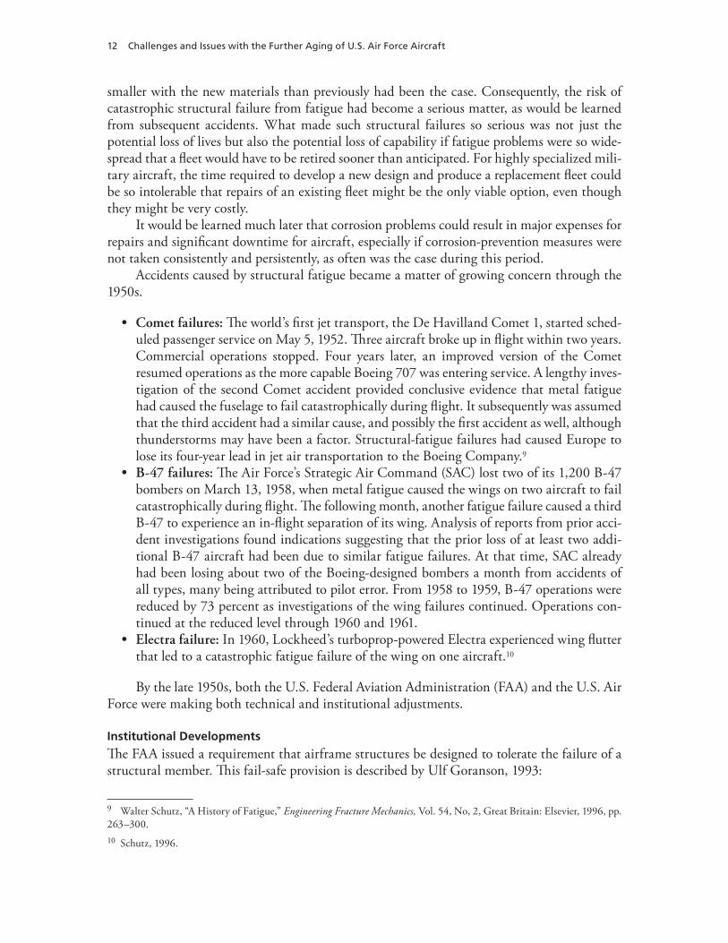
Comet failures:• The world’s first jet transport, the De Havilland Comet 1, started sched-uled passenger service on May 5, 1952. Three aircraft broke up in flight within two years. Commercial operations stopped. Four years later, an improved version of the Comet resumed operations as the more capable Boeing 707 was entering service. A lengthy inves-tigation of the second Comet accident provided conclusive evidence that metal fatigue had caused the fuselage to fail catastrophically during flight. It subsequently was assumed that the third accident had a similar cause, and possibly the first accident as well, although thunderstorms may have been a factor. Structural-fatigue failures had caused Europe to lose its four-year lead in jet air transportation to the Boeing Company.9B-47 failures:• The Air Force’s Strategic Air Command (SAC) lost two of its 1,200 B-47 bombers on March 13, 1958, when metal fatigue caused the wings on two aircraft to fail catastrophically during flight. The following month, another fatigue failure caused a third B-47 to experience an in-flight separation of its wing. Analysis of reports from prior acci-dent investigations found indications suggesting that the prior loss of at least two addi-tional B-47 aircraft had been due to similar fatigue failures. At that time, SAC already had been losing about two of the Boeing-designed bombers a month from accidents of all types, many being attributed to pilot error. From 1958 to 1959, B-47 operations were reduced by 73 percent as investigations of the wing failures continued. Operations con-tinued at the reduced level through 1960 and 1961. Electra failure:• In 1960, Lockheed’s turboprop-powered Electra experienced wing flutter that led to a catastrophic fatigue failure of the wing on one aircraft.10
By the late 1950s, both the U.S. Federal Aviation Administration (FAA) and the U.S. Air Force were making both technical and institutional adjustments.
Institutional Developments
The FAA issued a requirement that airframe structures be designed to tolerate the failure of a structural member. This fail-safe provision is described by Ulf Goranson, 1993:
9 Walter Schutz, “A History of Fatigue,” Engineering Fracture Mechanics, Vol. 54, No, 2, Great Britain: Elsevier, 1996, pp. 263–300.10 Schutz, 1996.
Historical Developments Relevant to the Further Aging of U.S. Air Force Aircraft 13
The key objective for airplane structure designed to the damage tolerance concept has always been to carry regulatory fail-safe loads until detection and repair of any fatigue cracks, corrosion, or accidental damage occurring in service [has occurred].11
In May 1958, the Air Force instituted its Aircraft Structural Integrity Program (ASIP) when the Air Force Chief of Staff, General Curtis LeMay, signed a memorandum that estab-lished three objectives for ASIP:
Control structural failure of operational aircraft•Determine methods of accurately predicting aircraft service life•Provide design and test approaches that would avoid structural fatigue problems in future •aircraft.
In November 1958, LeMay issued a policy directive that directed major operating com-mands to work with the Air Force’s engineers in implementing ASIP.
The Second 15-Year Period, 1963–1977
Notwithstanding prior institutional developments that were aimed at solving the fatigue prob-lem for airframe structures, efforts by both the FAA and the Air Force continued well into the Air Force’s second 15-year period.
Technical Developments
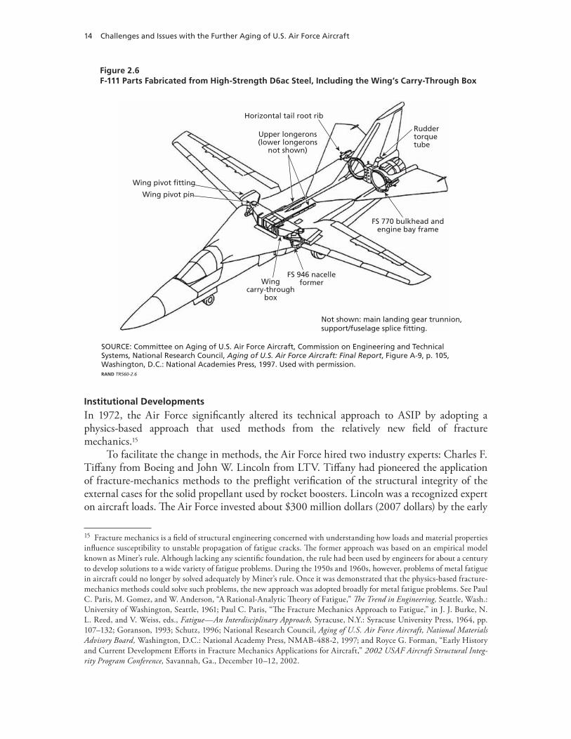
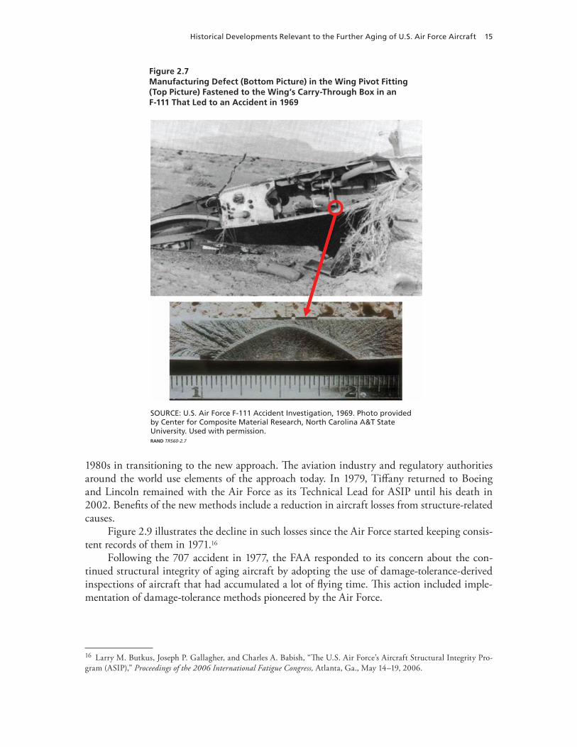
In 1969, the Air Force lost a relatively new F-111 aircraft (Figure 2.6) when structural fatigue caused the wing to fail after flying only 107 hours since delivery to the Air Force. Although the failed component (Figure 2.7) had been built from a high-strength D6ac steel, that type of steel was found to be very intolerant of fatigue cracking, because cracks grew rapidly in that material and because even small cracks would result in unstable propagation and failure when a cracked part experienced flight loads. During pull-up from a rocket-firing pass, a fatigue crack12 that was emerging from a manufacturing defect in the lower plate of the left wing pivot fitting13 caused the catastrophic failure.
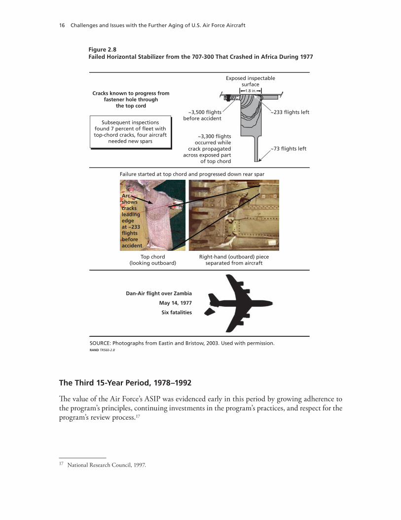
In 1977, fatigue failure caused the horizontal stabilizer on a 707-300 freighter to separate from the aircraft, resulting in the loss of the aircraft and its crew (Figure 2.8).14 A fatigue crack had propagated through the upper-rear spar over the course of many thousands of flights. The crack caused the spar to fracture during a flight that occurred about 233 flights before the accident. During that 233-flight period, the crack propagated down the rear spar web, even-tually causing the web and the lower spar to fail, whereupon the stabilizer separated from the aircraft.
11 Ulf G. Goranson, “Damage Tolerance Facts and Fiction,” Lincoln Award Lecture, 2006 Conference of USAF Aircraft Structural Integrity Program, San Antonio, Tex., November 28–30, 2006; also 14th Plantema Memorial Lecture presented at the 17th Symposium of the International Committee on Aeronautical Fatigue, Stockholm, Sweden, June 9, 1993.12 See the area below the arrowhead drawn on the lower picture in Figure 2.7.13 See the red circle drawn on the upper picture in Figure 2.7.14 Robert G. Eastin and John W. Bristow, “Looking at Lusaka’s Lessons,” Proceedings of the 2003 USAF Aircraft Structural Integrity Program Conference, Savannah, Ga., December 2–4, 2003.
14 Challenges and Issues with the Further Aging of U.S. Air Force Aircraft
Figure 2.6F-111 Parts Fabricated from High-Strength D6ac Steel, Including the Wing’s Carry-Through Box
SOURCE: Committee on Aging of U.S. Air Force Aircraft, Commission on Engineering and Technical Systems, National Research Council, Aging of U.S. Air Force Aircraft: Final Report, Figure A-9, p. 105, Washington, D.C.: National Academies Press, 1997. Used with permission.RAND TR560-2.6
Wing pivot pin
Wing pivot fitting
Upper longerons(lower longerons
not shown)
Horizontal tail root rib
Ruddertorquetube
FS 770 bulkhead andengine bay frame
FS 946 nacelleformer
Not shown: main landing gear trunnion,support/fuselage splice fitting.
Wingcarry-through
box
Institutional Developments
In 1972, the Air Force significantly altered its technical approach to ASIP by adopting a physics-based approach that used methods from the relatively new field of fracture mechanics.15
To facilitate the change in methods, the Air Force hired two industry experts: Charles F. Tiffany from Boeing and John W. Lincoln from LTV. Tiffany had pioneered the application of fracture-mechanics methods to the preflight verification of the structural integrity of the external cases for the solid propellant used by rocket boosters. Lincoln was a recognized expert on aircraft loads. The Air Force invested about $300 million dollars (2007 dollars) by the early
15 Fracture mechanics is a field of structural engineering concerned with understanding how loads and material properties influence susceptibility to unstable propagation of fatigue cracks. The former approach was based on an empirical model known as Miner’s rule. Although lacking any scientific foundation, the rule had been used by engineers for about a century to develop solutions to a wide variety of fatigue problems. During the 1950s and 1960s, however, problems of metal fatigue in aircraft could no longer by solved adequately by Miner’s rule. Once it was demonstrated that the physics-based fracture-mechanics methods could solve such problems, the new approach was adopted broadly for metal fatigue problems. See Paul C. Paris, M. Gomez, and W. Anderson, “A Rational-Analytic Theory of Fatigue,” The Trend in Engineering, Seattle, Wash.: University of Washington, Seattle, 1961; Paul C. Paris, “The Fracture Mechanics Approach to Fatigue,” in J. J. Burke, N. L. Reed, and V. Weiss, eds., Fatigue—An Interdisciplinary Approach, Syracuse, N.Y.: Syracuse University Press, 1964, pp. 107–132; Goranson, 1993; Schutz, 1996; National Research Council, Aging of U.S. Air Force Aircraft, National Materials Advisory Board, Washington, D.C.: National Academy Press, NMAB-488-2, 1997; and Royce G. Forman, “Early History and Current Development Efforts in Fracture Mechanics Applications for Aircraft,” 2002 USAF Aircraft Structural Integ-rity Program Conference, Savannah, Ga., December 10–12, 2002.
Historical Developments Relevant to the Further Aging of U.S. Air Force Aircraft 15
Figure 2.7Manufacturing Defect (Bottom Picture) in the Wing Pivot Fitting (Top Picture) Fastened to the Wing’s Carry-Through Box in an F-111 That Led to an Accident in 1969
SOURCE: U.S. Air Force F-111 Accident Investigation, 1969. Photo provided by Center for Composite Material Research, North Carolina A&T State University. Used with permission.RAND TR560-2.7
1980s in transitioning to the new approach. The aviation industry and regulatory authorities around the world use elements of the approach today. In 1979, Tiffany returned to Boeing and Lincoln remained with the Air Force as its Technical Lead for ASIP until his death in 2002. Benefits of the new methods include a reduction in aircraft losses from structure-related causes.
Figure 2.9 illustrates the decline in such losses since the Air Force started keeping consis-tent records of them in 1971.16
Following the 707 accident in 1977, the FAA responded to its concern about the con-tinued structural integrity of aging aircraft by adopting the use of damage-tolerance-derived inspections of aircraft that had accumulated a lot of flying time. This action included imple-mentation of damage-tolerance methods pioneered by the Air Force.
16 Larry M. Butkus, Joseph P. Gallagher, and Charles A. Babish, “The U.S. Air Force’s Aircraft Structural Integrity Pro-gram (ASIP),” Proceedings of the 2006 International Fatigue Congress, Atlanta, Ga., May 14–19, 2006.
16 Challenges and Issues with the Further Aging of U.S. Air Force Aircraft
Figure 2.8Failed Horizontal Stabilizer from the 707-300 That Crashed in Africa During 1977
SOURCE: Photographs from Eastin and Bristow, 2003. Used with permission.RAND TR560-2.8
Top chord(looking outboard)
Right-hand (outboard) pieceseparated from aircraft
Failure started at top chord and progressed down rear spar
Arcshowscracksleadingedgeat ~233flightsbeforeaccident
Dan-Air flight over Zambia
May 14, 1977
Six fatalities
Cracks known to progress fromfastener hole through
the top cord
Subsequent inspectionsfound 7 percent of fleet withtop-chord cracks, four aircraft
needed new spars
Exposed inspectablesurface
1.8 in.
~233 flights left
~73 flights left
~3,500 flightsbefore accident
~3,300 flightsoccurred while
crack propagatedacross exposed part
of top chord
The Third 15-Year Period, 1978–1992
The value of the Air Force’s ASIP was evidenced early in this period by growing adherence to the program’s principles, continuing investments in the program’s practices, and respect for the program’s review process.17
17 National Research Council, 1997.
Historical Developments Relevant to the Further Aging of U.S. Air Force Aircraft 17
Technical Developments
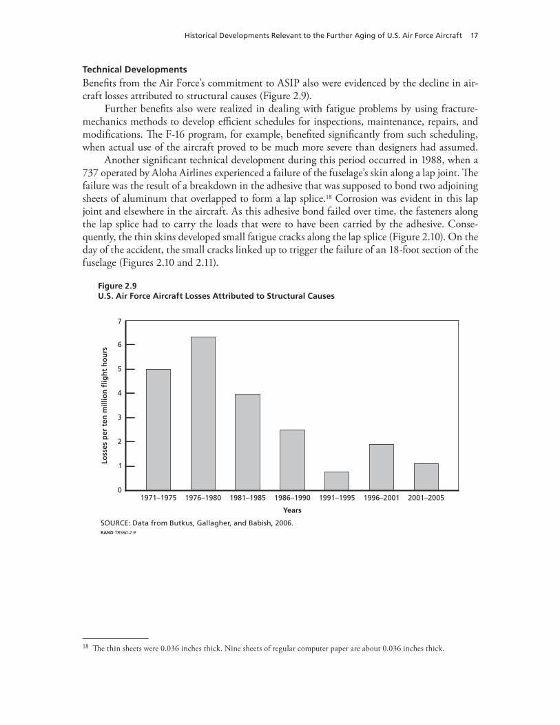
Benefits from the Air Force’s commitment to ASIP also were evidenced by the decline in air-craft losses attributed to structural causes (Figure 2.9).
Further benefits also were realized in dealing with fatigue problems by using fracture-mechanics methods to develop efficient schedules for inspections, maintenance, repairs, and modifications. The F-16 program, for example, benefited significantly from such scheduling, when actual use of the aircraft proved to be much more severe than designers had assumed.
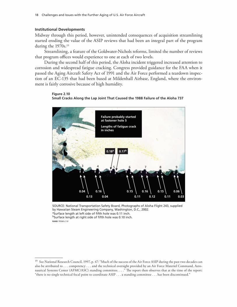
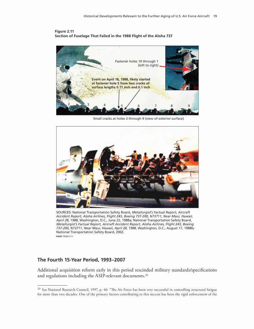
Another significant technical development during this period occurred in 1988, when a 737 operated by Aloha Airlines experienced a failure of the fuselage’s skin along a lap joint. The failure was the result of a breakdown in the adhesive that was supposed to bond two adjoining sheets of aluminum that overlapped to form a lap splice.18 Corrosion was evident in this lap joint and elsewhere in the aircraft. As this adhesive bond failed over time, the fasteners along the lap splice had to carry the loads that were to have been carried by the adhesive. Conse-quently, the thin skins developed small fatigue cracks along the lap splice (Figure 2.10). On the day of the accident, the small cracks linked up to trigger the failure of an 18-foot section of the fuselage (Figures 2.10 and 2.11).
Figure 2.9U.S. Air Force Aircraft Losses Attributed to Structural Causes
SOURCE: Data from Butkus, Gallagher, and Babish, 2006.RAND TR560-2.9
7
6
4
2
01976–19801971–1975 1981–1985 1986–1990 2001–20051996–20011991–1995
Years
Loss
es p
er t
en m
illio
n fl
igh
t h
ou
rs
1
5
3
18 The thin sheets were 0.036 inches thick. Nine sheets of regular computer paper are about 0.036 inches thick.
18 Challenges and Issues with the Further Aging of U.S. Air Force Aircraft
Institutional Developments
Midway through this period, however, unintended consequences of acquisition streamlining started eroding the value of the ASIP reviews that had been an integral part of the program during the 1970s.19
Streamlining, a feature of the Goldwater-Nichols reforms, limited the number of reviews that program offices would experience to one at each of two levels.
During the second half of this period, the Aloha incident triggered increased attention to corrosion and widespread fatigue cracking. Congress provided guidance for the FAA when it passed the Aging Aircraft Safety Act of 1991 and the Air Force performed a teardown inspec-tion of an EC-135 that had been based at Mildenhall Airbase, England, where the environ-ment is fairly corrosive because of high humidity.
Figure 2.10Small Cracks Along the Lap Joint That Caused the 1988 Failure of the Aloha 737
SOURCE: National Transportation Safety Board, Photographs of Aloha Flight 243, supplied by Hawaiian Steam Engineering Company, Washington, D.C., 2002.aSurface length at left side of fifth hole was 0.11 inch.bSurface length at right side of fifth hole was 0.10 inch.RAND TR560-2.10
Failure probably startedat fastener hole 5
Lengths of fatigue crackin inches
0.18a 0.17b
0.04
0.13
0.16
0.04
0.15
0.11
0.16
0.12
0.15
0.11
0.06
0.03
8765432 9
19 See National Research Council, 1997, p. 47: “Much of the success of the Air Force ASIP during the past two decades can also be attributed to . . . competency . . . and the technical oversight provided by an Air Force Materiel Command, Aero-nautical Systems Center (AFMC/ASC) standing committee. . . .” The report then observes that at the time of the report: “there is no single technical focal point to coordinate ASIP . . . a standing committee . . . has been discontinued.”
Historical Developments Relevant to the Further Aging of U.S. Air Force Aircraft 19
Figure 2.11Section of Fuselage That Failed in the 1988 Flight of the Aloha 737
SOURCES: National Transportation Safety Board, Metallurgist’s Factual Report, Aircraft Accident Report, Aloha Airlines, Flight 243, Boeing 737-200, N73711, Near Maui, Hawaii, April 28, 1988, Washington, D.C., June 22, 1988a; National Transportation Safety Board, Metallurgist’s Factual Report, Aircraft Accident Report, Aloha Airlines, Flight 243, Boeing 737-200, N73711, Near Maui, Hawaii, April 28, 1988, Washington, D.C., August 17, 1988b; National Transportation Safety Board, 2002.RAND TR560-2.11
Event on April 18, 1988, likely startedat fastener hole 5 from two cracks ofsurface lengths 0.11 inch and 0.1 inch
Fastener holes 10 through 1(left to right)
Small cracks at holes 3 through 9 (view of exterior surface)
8765432 9
The Fourth 15-Year Period, 1993–2007
Additional acquisition reform early in this period rescinded military standards/specifications and regulations including the ASIP-relevant documents.20
20 See National Research Council, 1997, p. 46: “The Air Force has been very successful in controlling structural fatigue for more than two decades. One of the primary factors contributing to this success has been the rigid enforcement of the
20 Challenges and Issues with the Further Aging of U.S. Air Force Aircraft
Technical Developments
In 1999, an aging-related failure of a component in the horizontal stabilizer system is believed to have created a runaway trim condition that caused the loss of a KC-135 as it was attempting to climb following an aborted landing near Geilenkirchen, Germany. A number of candidate scenarios have been identified where a known aging problem with any one of five mechanical/electrical components could have caused the accident. Because of the intense fire following the accident, a definitive determination of the cause could not be made.
Structural failure apparently caused the loss of two F-15 aircraft—one in 2002 when the honeycomb leading edge of the vertical stabilizer failed during supersonic flight and the other in 2007 when most of the forward fuselage separated from the aircraft.21
Institutional Developments
The Air Force had its Scientific Advisory Board conduct a major study of aircraft life extension and mission enhancement during 1994. It then asked the National Research Council (NRC) to sponsor a study (its report was issued in 1997) of how research might mitigate the vulner-abilities of aging. It reinvigorated the old ASIP MIL-STD 1530 during 2005 as a standard- practices document (issued as MIL-STD 1530C). The document now includes a more com-plete treatment of certification and sustainment practices. However, an Air Force Policy Direc-tive (AFPD 63-10) and its implementing instruction (AFI 63-1001) continue to direct program managers to tailor the use of ASIP practices to the needs of their programs.22 Hoever, there is no established process for reviewing either the tailoring process or the results of the process.
Charles F. Tiffany’s Perspective in 1997. Charles F. Tiffany, the person in charge of the U.S. Air Force ASIP from 1972 to 1979, wrote in 1997, as chair of the NRC study:23
ASIP. Internal compliance by Air Force management was directed by AFR 80-13, and contractor compliance was achieved by making MIL-STD 1530 and supporting specifications part of a weapon system contract. . . .” The report then observes that “the committee is very concerned that ASIP, per MIL-STD 1530 and its supporting specifications, will no longer be placed on aircraft acquisition and modification contracts due to former Secretary of Defense Perry’s initiative to reduce the use of government specifications in acquisition programs.” 21 The Air Force reported in a press release on October 4, 2002, that the accident investigation board “said there is clear and convincing evidence that structural failure of the honeycomb material supporting the leading edge of the left vertical stabilizer during a high-speed test dive was the primary cause of the crash. At about 24,000 feet and at an airspeed of about 900 mph, the aircraft experienced the structural failure which caused part of the tail to break off and the fighter to depart from controlled flight. The departure created other structural overloads that resulted in the aircraft breaking up.”22 Policy direction in AFPD 63-10:
“4. This directive establishes the following authorities and responsibilities: . . .” •
“4.5. Program managers shall ensure that an appropriate ASIP is developed and documented for each aircraft weapon •system the Air Force is acquiring or using. In addition, they shall monitor execution of the plan to ensure its effectiveness.”
“5. This directive relates to instructions in AFI 63-1001,• Aircraft Structural Integrity Program, which implements this directive.”
Implementing instructions in Air Force Instruction (AFI) 63-1001:
“2.1. ASIP, as described in MIL-HDBK-1530, is tailored as appropriate for application to all piloted aircraft devel-oped or used by the Air Force.”
23 National Research Council, 1997.
Historical Developments Relevant to the Further Aging of U.S. Air Force Aircraft 21
the committee is concerned that the extended use of old aircraft, coupled with the poten-tially adverse effects of reduced military budgets; reduced manpower; grade structure lim-itations; increased reliance on contractor maintenance; the elimination or relaxation of military regulations, standards, and specifications; and possible complacency of Air Force management, may make this past success rather fragile. The committee believes that it will take aggressive Air Force management and engineering actions to counter this deterioration in capability and loss in ASIP oversight and prevent further deterioration in the future.
John W. Lincoln’s Perspective in 2001. John W. Lincoln, the person in charge of ASIP from 1980 to 2002, wrote in 2001:24
The United States Air Force (USAF) is keeping aircraft in their inventories longer than ever before. In many cases, aircraft are left in the inventory longer because they are still opera-tionally effective; however, in most cases, they remain in the inventory because the money is not available to replace them. These aircraft are seeing the effects of aging through cor-rosion, fatigue cracking, material degradation, and wear. These effects are causing opera-tors to bear a significant economic burden to keep them operational with the potential for degradation of flight safety if they are not maintained properly. Consequently, the USAF is caught in a “death spiral” since aging aircraft funding requirements are inhibiting its abil-ity to procure new systems.
Joseph P. Gallagher’s Perspective in 2007. Joseph P. Gallagher, the person in charge of ASIP from 2002 to 2007, wrote in 2008:25
The evolution of the current approach for airframes has been driven by three factors: (1) budgets which reduced sustainment resources, especially for engineering support of long-term decisions, (2) overwhelming numbers of older aircraft that continuously need additional capability to meet evolving threats and satisfy new mission requirements, and (3) policy changes which de-emphasized adherence to integrity principles and system- engineering processes.
Supporting Gallagher’s perspective were the results of the reviews (Tables 2.2 and 2.3) that he conducted during 2004, 2005, and 2006.26
24 Personal communication with an associate of John W. Lincoln, 2002.25 Personal communication with Joseph P. Gallagher, 2008.26 Gallagher, 2007.
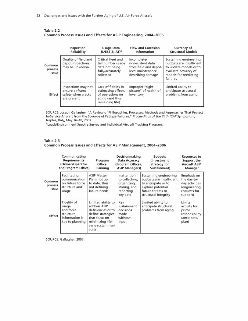
22 Challenges and Issues with the Further Aging of U.S. Air Force Aircraft
Table 2.2Common Process Issues and Effects for ASIP Engineering, 2004–2006
SOURCE: Joseph Gallagher, “A Review of Philosophies, Processes, Methods and Approaches That Protect In-Service Aircraft from the Scourge of Fatigue Failures,” Proceedings of the 24th ICAF Symposium, Naples, Italy, May 16–18, 2007.aLoads/Environment Spectra Survey and Individual Aircraft Tracking Program.
Commonprocess
issue
Effect
Inspection Reliability
Usage Data (L/ESS & IAT)a
Flaw and Corrosion Information
Currency of Structural Models
Inspections may not ensure airframe safety when cracksare present
Lack of fidelity inestimating effectsof operations onaging (and thus remaining life)
Improper “sightpicture” of health of inventory
Limited ability toanticipate structural problems from aging
Quality of field anddepot inspections may be unknown
Critical fleet andtail number usagedata not beingfully/accurately collected
Incomplete/nonexistent data from field and depot-level maintenance describing damage
Sustaining engineering budgets are insufficientto update models or toevaluate accuracy of models for predicting failures
Table 2.3Common Process Issues and Effects for ASIP Management, 2004–2006
SOURCE: Gallagher, 2007.
Commonprocess
issue
Effect
Resources to Support the Aircraft ASIP
Manager
Budgets (Investment Strategy for Sustainment)
Decisionmaking Data Accuracy
(Program Offices, ASIP Managers)
ProgramOffice
Planning
Limitsactivity forprime responsibility (anticipate/plan)
Limited ability toanticipate structural problems from aging
Key sustainment decisions madewithout input
Limited ability toaddress ASIP deficiencies or to define strategies that focus on minimizing life-cycle sustainmentcosts
Fidelity of usage and force structure information iskey to planning
Emphasis on the day-to-day activities (engineering requests for support)
Sustaining engineering budgets are insufficient to anticipate or toexplore potentialfuture threats to structural integrity
Inattention to collecting, organizing, storing, and reporting key data
ASIP Master Plans not up to date, thus not defining future needs
Facilitating communication on future force structure and usage
Communicating Requirements
(Owner/Operator and Program Office)
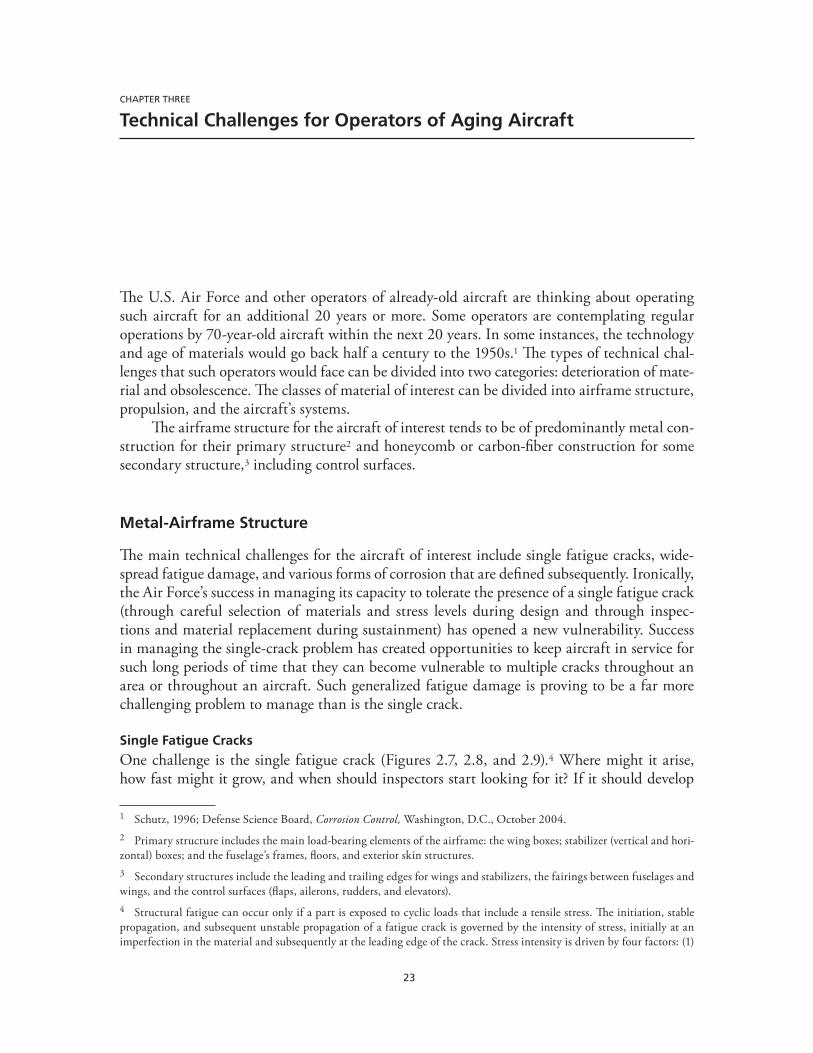
23
CHAPTER THREE
Technical Challenges for Operators of Aging Aircraft
The U.S. Air Force and other operators of already-old aircraft are thinking about operating such aircraft for an additional 20 years or more. Some operators are contemplating regular operations by 70-year-old aircraft within the next 20 years. In some instances, the technology and age of materials would go back half a century to the 1950s.1 The types of technical chal-lenges that such operators would face can be divided into two categories: deterioration of mate-rial and obsolescence. The classes of material of interest can be divided into airframe structure, propulsion, and the aircraft’s systems.
The airframe structure for the aircraft of interest tends to be of predominantly metal con-struction for their primary structure2 and honeycomb or carbon-fiber construction for some secondary structure,3 including control surfaces.
Metal-Airframe Structure
The main technical challenges for the aircraft of interest include single fatigue cracks, wide-spread fatigue damage, and various forms of corrosion that are defined subsequently. Ironically, the Air Force’s success in managing its capacity to tolerate the presence of a single fatigue crack (through careful selection of materials and stress levels during design and through inspec-tions and material replacement during sustainment) has opened a new vulnerability. Success in managing the single-crack problem has created opportunities to keep aircraft in service for such long periods of time that they can become vulnerable to multiple cracks throughout an area or throughout an aircraft. Such generalized fatigue damage is proving to be a far more challenging problem to manage than is the single crack.
Single Fatigue Cracks
One challenge is the single fatigue crack (Figures 2.7, 2.8, and 2.9).4 Where might it arise, how fast might it grow, and when should inspectors start looking for it? If it should develop
1 Schutz, 1996; Defense Science Board, Corrosion Control, Washington, D.C., October 2004.2 Primary structure includes the main load-bearing elements of the airframe: the wing boxes; stabilizer (vertical and hori-zontal) boxes; and the fuselage’s frames, floors, and exterior skin structures. 3 Secondary structures include the leading and trailing edges for wings and stabilizers, the fairings between fuselages and wings, and the control surfaces (flaps, ailerons, rudders, and elevators).4 Structural fatigue can occur only if a part is exposed to cyclic loads that include a tensile stress. The initiation, stable propagation, and subsequent unstable propagation of a fatigue crack is governed by the intensity of stress, initially at an imperfection in the material and subsequently at the leading edge of the crack. Stress intensity is driven by four factors: (1)
24 Challenges and Issues with the Further Aging of U.S. Air Force Aircraft
undetected and grow into a catastrophic structural failure that causes the inflight breakup of the structure, will the part that caused the crash be found? How will inspectors know what to look for in a postaccident inspection of a fleet? These are the kinds of technical challenges the Air Force faced during the late 1950s with its fleet of 1,200 B-47 bombers that formed the backbone of the strategic bomber force at that time.
The ASIP practices now described in MIL-STD 1530C (and previously described in the ASIP documents developed during the 1970s) were developed to make structural failure extraordinarily unlikely.5 By 1991, such practices achieved a success rate of about one chance of catastrophic failure in 10,000,000 flight hours.6 The Air Force demonstrated that it was pos-sible to manage the technical challenges of the single fatigue crack through rigorous adherence to proven practices of ASIP that include (1) using full-scale fatigue tests and service experience to identify fatigue critical locations (FCLs), (2) following up with damage tolerance analyses that calculated inspection requirements, and (3) scheduling inspections of FCLs in the force structural maintenance plan (FSMP).
Widespread Fatigue Damage
Another challenge is a high concentration of small fatigue cracks in a significant area of the structure (Figure 2.11). Such a concentration may occur at multiple sites in a single structural member (multiple site damage), such as in the segment of skin depicted in Figure 2.11, or it may occur in multiple structural members (multiple element damage). Many of the questions of interest relating to widespread fatigue damage parallel the foregoing questions for the single fatigue crack. Where might widespread cracking arise? How fast might it develop? When should inspectors start looking for it? What kind of inspection would be required to find it? If it should develop undetected and grow into a catastrophic structural failure that causes the violent in-flight breakup of the aircraft, will the part that caused the crash be found? How will inspectors know what to look for in any postaccident inspection of a fleet? The Air Force’s recognition of this challenge during the early 1970s was a result of its adoption of fracture mechanics as the physics-based approach to understanding and managing structural fatigue. It was not until the late 1980s, however, that the Aloha 737 accident forced heightened interest
the size of the imperfection/crack, (2) the peak magnitude of the tensile stress near the crack for a stress reversal cycle, (3) the minimum stress for that cycle, and (4) details regarding the geometry of the part in the vicinity of the imperfection/crack. Once the stress intensity reaches the level of the fracture toughness of the material, the crack increases in size (unstable growth) until either the part fails or the propagation is arrested. Arrest can occur, for example, when a crack encounters a fastener hole or one edge of a part.5 Paris, Gomez, and Anderson, 1961; Paris, 1964; M. D. Coffin and Charles F. Tiffany, “New Air Force Requirements for Structural Safety, Durability, and Life Management,” Journal of Aircraft, Vol. 13, No. 2, February 1976, pp. 93–98; Jean R. Gebman and Paul C. Paris, Probability That the Propagation of an Undetected Fatigue Crack Will Not Cause a Structural Failure, Santa Monica, Calif.: RAND Corporation, R-2238-RC, 1978; Jean R. Gebman and Paul C. Paris, “Probability That the Propagation of an Undetected Fatigue Crack Will Not Cause a Structural Failure,” Fatigue Crack Growth Measurement and Analysis, American Society for Testing and Materials, STP-738, 1979; John W. Lincoln, “Aging Aircraft Issues in the United States Air Force,” SAMPE Journal, Vol. 32, No. 5, 1996, pp. 27–33; John W. Lincoln, Risk Assessments of Aging Air-craft, Ogden, Utah: DoD/FAA/NASA Conference on Aging Aircraft, July 8–10, 1997; National Research Council, 1997; Forman, 2002; Yool Kim, Stephen Sheehy, and Darryl Lenhardt, A Survey of Aircraft Structural-Life Management Programs in the U.S. Navy, the Canadian Forces, and the U.S. Air Force, Santa Monica, Calif.: RAND Corporation, MG-370-AF, 2006; Butkus, Gallagher, and Babish, 2006; Gallagher, 2007.6 Goranson (1993, p. 6) reports that as of 1993, the “ASIP philosophy used since 1975 has been extremely effective in ensuring structural safety by reducing hull losses by about 80%.”
Technical Challenges for Operators of Aging Aircraft 25
of the aviation community on the challenges presented by widespread fatigue damage. Twenty years later, however, the FAA is still working to develop an approach for assuring the airwor-thiness of those aircraft that may be operated under circumstances where widespread fatigue cracking may threaten airworthiness.7
The Aloha accident in 1988 (Figures 2.10 and 2.11) demonstrated how small cracks can link up to form a very large crack that results in the failure of a large section of significant structure.8 Detecting such cracks before the failure of a large section of significant structure is a major challenge for the aviation industry because of the limitations of current inspection meth-ods. Even knowing where to inspect and what aircraft to inspect are major challenges because of the variety of uses that a fleet is put to and the lack of relevant fatigue tests for some aircraft that have experienced modifications, changes in use, or variability in cumulative use. For all of these reasons, the pace of developments to provide rigorous protection against both widespread and generalized fatigue damage has been slow for both the FAA and Air Force.
Generalized Fatigue Damage
As fatigue cracks reach significant sizes in multiple areas of a structure, the inspection burden increases and the costs of maintenance and modifications rise. As the economic burdens of such activities rise, either the economic viability of continued operations declines or, in the cir-cumstance of constrained resources, the risk of failure rises as available maintenance resources are tasked to execute an expanding set of inspections without additional resources. As the volume of significant cracking raises the requirement for inspections (or modifications) to levels that may be deemed unacceptable, such a state of cracking can be referred to as general-ized fatigue damage (GFD). A state of GFD may be the result of widespread fatigue damage (WFD) occurring in many different areas of a structure.
Stress Corrosion Cracking
The class of corrosion problems known as stress corrosion cracking (SCC) (Figure 3.1) can manifest in a wide variety of ways. The common cause attributed to this class of problems includes the presence of both a corrosion process9 and a stress that is perpendicular to the
7 The National Research Council, 1997, report and the Air Force’s ASIP managers have taken the position that there are only two acceptable options for dealing with the threat of widespread fatigue damage to significant structure: either replace the threatened area or retire the aircraft.8 National Transportation Safety Board, 1988a, 1988b, 2002; National Transportation Safety Board, Aircraft Accident Report, Aloha Airlines, Flight 243, Boeing 737-200, N73711, Near Maui, Hawaii, April 28, 1988, NTSB/AAR-89-03, Wash-ington, D.C., 1989.9 Metals are vulnerable to corrosion because (1) the nucleus of each metal atom exists in a common pool of highly mobile electrons, (2) when moisture forms a waterway between two metal parts, electrons may migrate from one part to the other part via the waterway, and (3) such migration can alter the chemical composition of the parts. Such alteration is the electro-chemical process known as corrosion. The most severe corrosion occurs when the electrical potential of two metals has the greatest difference.
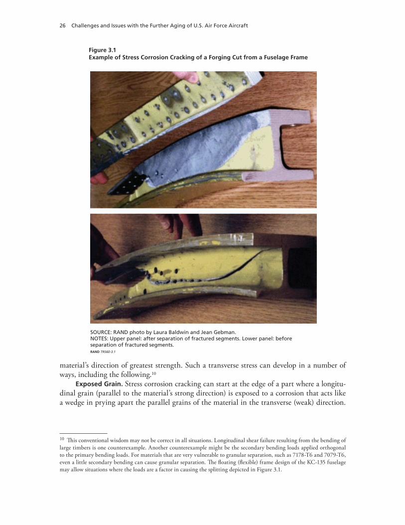
26 Challenges and Issues with the Further Aging of U.S. Air Force Aircraft
Figure 3.1Example of Stress Corrosion Cracking of a Forging Cut from a Fuselage Frame
SOURCE: RAND photo by Laura Baldwin and Jean Gebman.NOTES: Upper panel: after separation of fractured segments. Lower panel: beforeseparation of fractured segments.RAND TR560-3.1
material’s direction of greatest strength. Such a transverse stress can develop in a number of ways, including the following.10
Exposed Grain. Stress corrosion cracking can start at the edge of a part where a longitu-dinal grain (parallel to the material’s strong direction) is exposed to a corrosion that acts like a wedge in prying apart the parallel grains of the material in the transverse (weak) direction.
10 This conventional wisdom may not be correct in all situations. Longitudinal shear failure resulting from the bending of large timbers is one counterexample. Another counterexample might be the secondary bending loads applied orthogonal to the primary bending loads. For materials that are very vulnerable to granular separation, such as 7178-T6 and 7079-T6, even a little secondary bending can cause granular separation. The floating (flexible) frame design of the KC-135 fuselage may allow situations where the loads are a factor in causing the splitting depicted in Figure 3.1.
Technical Challenges for Operators of Aging Aircraft 27
Such behavior is a consequence of the fact that the by-products of corrosion require more volume than the material that is consumed in the corrosion process.
Residual Stress. Internal stresses, known as residual stresses, can be created when a billet of material is rolled, extruded, or forged to form material that will be used to manufacture apart such as a skin, plate, frame, longeron, stiffener, or bulkhead.11 Corrosion in an area with residual stress can result in stress corrosion cracking.
Fabrication Stress. When parts are fastened together to form joints, the clamping together of the parts can create transverse stresses known as clamp-up stresses. Again, if an area with such a clamp-up stress is exposed to corrosion, the result can be stress corrosion cracking.
Certain aluminum alloys, certain heat treatments, and certain methods of forming mate-rials have been found to generate situations that are very vulnerable to such cracking. For example, forgings of 7079-T6 and 7178-T6 have manifested SCC problems in the KC-135 fleet. The intergranular separations have included forgings that have split much like a log might be split. See Figure 3.1 for a section of a forging that was removed from a -135 aircraft.
The discovery of corrosion in the KC-135 fleet and the extensive hidden corrosion discov-ered in the Aloha 737 contributed to the Air Force’s decision to tear apart a -135 aircraft that had a history of exposure to a corrosive environment as well as a history of corrosion mainte-nance. The selected aircraft was an EC-135 that had been based at Mildenhall Airbase, Eng-land, for much of its life. During 1992, the teardown inspection found many examples of stress corrosion cracking that alerted the Air Force to the potential significance of such a problem in its aging aircraft.12
Exfoliation Corrosion
The Mildenhall aircraft also provided many examples of another class of intergranular corrosion—one that features a bubbling up or flaking of material, similar to the flaking of lumber that has been attacked by termites (Figures 3.2 and 3.3). It generally is agreed that this class of corrosion does not include a stress mechanism.
The thick panels forming the upper surface of the wings on -135 aircraft have been found to be vulnerable to exfoliation corrosion at fastener holes where cadmium-coated steel fasteners join the skin panels to the interior substructure (Figure 3.3).13 Parts in the -135 aircraft that were fabricated from 7079-T6 and 7178-T6 aluminum have manifested significant vulnerabil-ity to exfoliation corrosion when the material is exposed to moisture.
A confounding factor can be the wearing down of the cadmium coating that prevents contact between the steel and aluminum. This coating is important because steel and alumi-num have a very high dissimilar-metals rating in terms of electrical potential. This results in
11 When a large rectangular block of an aluminum alloy is rolled into a thin sheet or thick plate, the strong crystal/grains tend to align themselves with the direction of rolling, called the longitudinal axis. The strength of the sheet/plate will be greatest in this longitudinal direction and weakest in the perpendicular directions (transverse and lateral). A similar situ-ation arises with the extrusion of parts such as stiffeners, spars, and longerons. Forgings not only are vulnerable to such directional strengths and weaknesses but, because of their complex shapes, they may have residual stresses within the part as a result of the forging process. No matter whether a part is rolled, extruded, or forged, the resulting alignment of grains means that granular separations are most likely to run along the longitudinal direction. 12 Donald E. Nieser, “Effects of Corrosion on C/KC-135 Structural Life and Flight Safety to 2040,” Proceedings of the Fourth Joint DoD/FAA/NASA Conference on Aging Aircraft, St. Louis, Mo., May 15–18, 2000. Also see National Research Council, 1997.13 Nieser, 2000.

28 Challenges and Issues with the Further Aging of U.S. Air Force Aircraft
Figure 3.2Example of Exfoliation Corrosion of Stiffeners That Were Removed from Inside the Center Box of a Horizontal Stabilizer
SOURCE: Donald E. Nieser, Photographs of Exhibits Depicting Corrosion of KC-135 Parts, provided to RAND staff, 2001. Used with permission.RAND TR560-3.2
high vulnerability to corrosion when moisture is present. The necessary practice of periodi-cally stripping paint and the underlying layer of primer to reestablish a reliable moisture bar-rier has had the undesired affect of wearing down the cadmium coating on the fastener heads. Because some skin panels already have been replaced on the wing’s upper surface, the Air Force expects that all panels will need to be replaced eventually, as has been the case with the for-ward fuselage’s belly skins. However, the Air Force expects that such mitigation measures as shot-peening of surfaces will close end grains and allow such replacement to be deferred until the 2020s.
Crevice Corrosion
Crevice corrosion can develop at the interface between two adjoining parts if each part is cor-rosion-prone and moisture makes contact with the surface of each part (Figure 3.4).
Applying one or more of three moisture barriers can protect against crevice corrosion: (1) a coating of sealant to the area where the parts will make contact to prevent moisture from providing an electrically conductive pathway between the parts, (2) a primer and top-coat paint to the parts before and after they have been joined to prevent moisture from entering the interface area where the parts make contact,14 and (3) a coating of corrosion-prevention com-pound on top of the aforementioned paint (such a caulking-like substance prevents moisture from making contact with the paint along the edges of the parts). When the aircraft were pro-duced, most joints in the KC-135 and the 707 structures were protected only by paint. Thus, as the structure experiences cyclic deformations, the ability of the paint to provide an adequate barrier to moisture penetration may degrade over time.
14 Flexing of parts during flight, however, may defeat such a measure if the integrity of the painting system is not main-tained to a high standard.
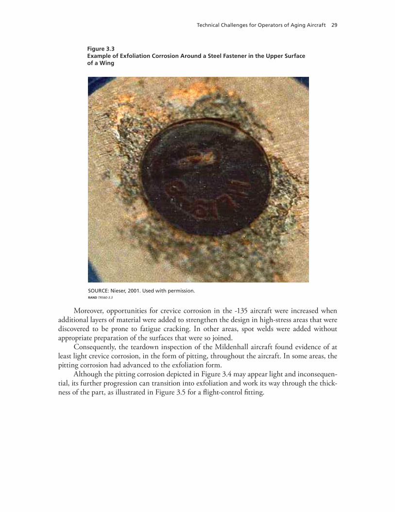
Technical Challenges for Operators of Aging Aircraft 29
Figure 3.3Example of Exfoliation Corrosion Around a Steel Fastener in the Upper Surface of a Wing
SOURCE: Nieser, 2001. Used with permission.RAND TR560-3.3
Moreover, opportunities for crevice corrosion in the -135 aircraft were increased when additional layers of material were added to strengthen the design in high-stress areas that were discovered to be prone to fatigue cracking. In other areas, spot welds were added without appropriate preparation of the surfaces that were so joined.
Consequently, the teardown inspection of the Mildenhall aircraft found evidence of at least light crevice corrosion, in the form of pitting, throughout the aircraft. In some areas, the pitting corrosion had advanced to the exfoliation form.
Although the pitting corrosion depicted in Figure 3.4 may appear light and inconsequen-tial, its further progression can transition into exfoliation and work its way through the thick-ness of the part, as illustrated in Figure 3.5 for a flight-control fitting.
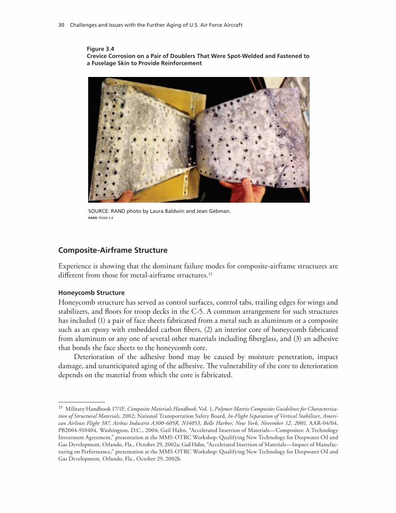
30 Challenges and Issues with the Further Aging of U.S. Air Force Aircraft
Figure 3.4Crevice Corrosion on a Pair of Doublers That Were Spot-Welded and Fastened to a Fuselage Skin to Provide Reinforcement
SOURCE: RAND photo by Laura Baldwin and Jean Gebman.RAND TR560-3.4
Composite-Airframe Structure
Experience is showing that the dominant failure modes for composite-airframe structures are different from those for metal-airframe structures.15
Honeycomb Structure
Honeycomb structure has served as control surfaces, control tabs, trailing edges for wings and stabilizers, and floors for troop decks in the C-5. A common arrangement for such structures has included (1) a pair of face sheets fabricated from a metal such as aluminum or a composite such as an epoxy with embedded carbon fibers, (2) an interior core of honeycomb fabricated from aluminum or any one of several other materials including fiberglass, and (3) an adhesive that bonds the face sheets to the honeycomb core.
Deterioration of the adhesive bond may be caused by moisture penetration, impact damage, and unanticipated aging of the adhesive. The vulnerability of the core to deterioration depends on the material from which the core is fabricated.
15 Military Handbook 17/1F, Composite Materials Handbook, Vol. 1, Polymer Matrix Composites Guidelines for Characteriza-tion of Structural Materials, 2002; National Transportation Safety Board, In-Flight Separation of Vertical Stabilizer, Ameri-can Airlines Flight 587, Airbus Industrie A300-605R, N14053, Belle Harbor, New York, November 12, 2001, AAR-04/04, PB2004-910404, Washington, D.C., 2004; Gail Hahn, “Accelerated Insertion of Materials—Composites: A Technology Investment Agreement,” presentation at the MMS-OTRC Workshop: Qualifying New Technology for Deepwater Oil and Gas Development, Orlando, Fla., October 29, 2002a; Gail Hahn, “Accelerated Insertion of Materials—Impact of Manufac-turing on Performance,” presentation at the MMS-OTRC Workshop: Qualifying New Technology for Deepwater Oil and Gas Development, Orlando, Fla., October 29, 2002b.
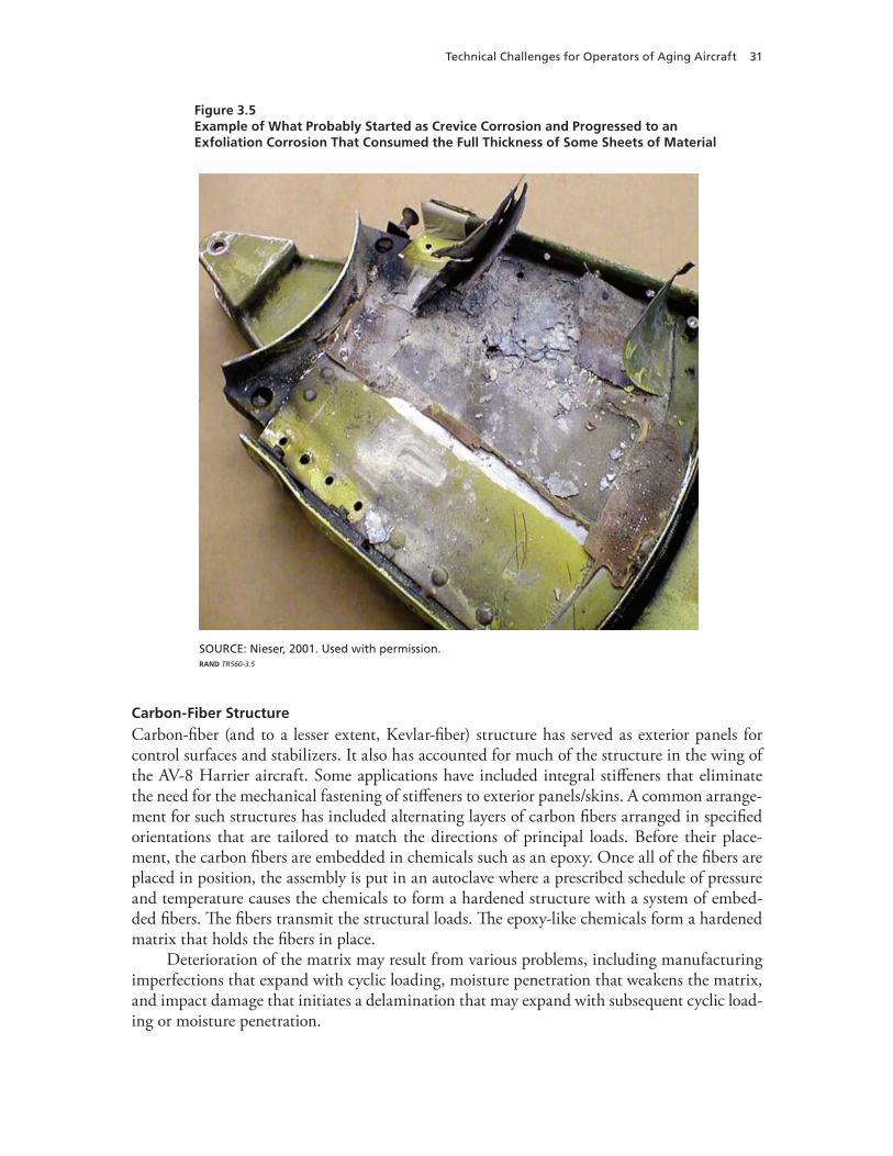
Technical Challenges for Operators of Aging Aircraft 31
Figure 3.5Example of What Probably Started as Crevice Corrosion and Progressed to an Exfoliation Corrosion That Consumed the Full Thickness of Some Sheets of Material
SOURCE: Nieser, 2001. Used with permission.RAND TR560-3.5
Carbon-Fiber Structure
Carbon-fiber (and to a lesser extent, Kevlar-fiber) structure has served as exterior panels for control surfaces and stabilizers. It also has accounted for much of the structure in the wing of the AV-8 Harrier aircraft. Some applications have included integral stiffeners that eliminate the need for the mechanical fastening of stiffeners to exterior panels/skins. A common arrange-ment for such structures has included alternating layers of carbon fibers arranged in specified orientations that are tailored to match the directions of principal loads. Before their place-ment, the carbon fibers are embedded in chemicals such as an epoxy. Once all of the fibers are placed in position, the assembly is put in an autoclave where a prescribed schedule of pressure and temperature causes the chemicals to form a hardened structure with a system of embed-ded fibers. The fibers transmit the structural loads. The epoxy-like chemicals form a hardened matrix that holds the fibers in place.
Deterioration of the matrix may result from various problems, including manufacturing imperfections that expand with cyclic loading, moisture penetration that weakens the matrix, and impact damage that initiates a delamination that may expand with subsequent cyclic load-ing or moisture penetration.

32 Challenges and Issues with the Further Aging of U.S. Air Force Aircraft
Propulsion
Material Deterioration
The technical challenges of cost-effectively sustaining propulsion systems in 50- and 70-year-old airframes may be far more tractable than sustaining airframes fabricated from 1950s mate-rials and 1950s technologies.
Engine Disassembly. Because engines experience far harsher environments and loads than airframes, engines are designed to be taken apart during the overhaul process; airframes are not. With engines, the expectation is that any part may be replaced one or more times during an engine’s life. With airframes, the assumption is that most parts will never be replaced. Con-sequently, disassembly and replacement of parts during regular overhaul is often a simpler task with an engine than it is with an airframe.
Engine Replacement. Also, the replacement of engines and their accessories with a new engine and a new set of accessories has proved to be a very cost-effective measure because the value of the replacement engine often justifies the replacement cost by providing more power, reduced fuel consumption, and lower maintenance cost. The benefiting aircraft has the poten-tial to take off with more payload, to fly a greater distance, and to incur a lower maintenance cost.
Technical Obsolescence
As engines age, the required scope of overhaul increases as more elements of the engine require, first, time, and then, subsequent overhaul work. Meanwhile, because of technical obsolescence, sources of supply diminish and the cost of producing parts that employ obsolete technologies rises, placing further upward pressure on maintenance costs. The chief technical challenge lies in assessing whether an aircraft will remain in service long enough to justify the investment in a new engine.
Assessing the level of assurance for obtaining a satisfactory return on an investment in new engines faces a number of challenges that become more serious with aircraft age. Will unforeseen circumstances force earlier-than-anticipated retirement of the fleet? Factors that might contribute to early retirement include rising costs of maintenance, changing threats, obsolescence of aircraft capabilities, and obsolescence of aircraft support capabilities.
Systems
For the purposes of this report, the systems category includes all material except the air-frame structure and the propulsion system (including engines and accessories). Wiring, cables, hydraulics, pneumatics, fuel, water, air conditioning, pumps, valves, motors, electronics, elec-trical, communications, flight control, landing gears, and mission equipment all are included in the systems category.
The technical challenges of cost-effectively sustaining aircraft systems in 50- and 70-year-old airframes are formidable. Will unforeseen circumstances force earlier-than-anticipated retirement of the fleet? Factors that might contribute to early retirement include rising cost of maintenance, changing threats, obsolescence of system capabilities, and obsolescence of system support.
Technical Challenges for Operators of Aging Aircraft 33
The technical challenges associated with the sustainment of systems in aging aircraft deserve substantial study, but we have not addressed those challenges in this report. Wiring, hydraulics, electrical systems, aviation electronics, fuel systems, environmental control sys-tems, and many other systems are subject to wear and deterioration that can contribute to rising problems over time with cost, availability, and safety.
A couple of factors may account for the lack, to date, of a more balanced study of systems.
A single system, unlike the airframe’s structure, is unlikely to cause the early retirement of a fleet. There has been a sense that systems problems can be dealt with as they arise. Of course, that can be faulty logic when enough systems get old enough that reliability, availability, costs, and safety become issues. This was recognized by the Air Force during the early 1990s when it started to develop a Functional Systems Integrity Program (FSIP) patterned after the ASIP.
Efforts to establish a strong FSIP, however, were starting at a time when support for ASIP was declining. One consequence of the lack of a well-established FSIP is a dearth of informa-tion about systems that could be drawn on for the present report. This deficiency will be dealt with in later chapters.
Material Deterioration
The materials constituting the systems category can deteriorate in many ways other than through fatigue and corrosion. Some systems such as fuel, hydraulics, and cabin pressuriza-tion can develop leaks that may endanger safe flight. Malfunctions or failures of flight-control components can endanger safe flight. Arcing of electrical wires, failure of insulation on electri-cal wires, and malfunctions or failures of electrical components can also endanger safe flight, if fires or explosions are a consequence of such deterioration.
Technical Obsolescence
Because aircraft systems often include many parts that were tailored specifically for applica-tion to a single fleet, or a few fleets manufactured during one era, acquiring replacement parts becomes progressively more difficult as an already-old fleet ages further. Frequently, retired aircraft from a fleet become important sources of spare parts. Once that source of supply runs dry, then parts may have to be reverse-engineered before they can be manufactured because of a lack of drawings or materials. At times, it will be less costly to design and manufacture a replacement assembly, such as a gearbox or piece of electronics. Sometimes, modern equipment used on contemporary aircraft might be used as replacement items, but integration of such equipment may be costly because of differences in form, fit, and function.

35
CHAPTER FOUR
Institutional Challenges for Operators of Aging Aircraft
The U.S. Air Force and other operators of already-old aircraft can expect to encounter difficult institutional challenges. For example, as already-old aircraft get even older, what will be their real state of health and how much additional attention will they need to remain cost-effective, if that is found to be even possible? The chief institutional challenges to even considering such questions include (1) limitations on independent verification of fleet status and limita-tions on independent verification of forecasts for future conditions, (2) limitations on informa-tion needed for engineering analyses including risk assessments, and (3) an overall scarcity of resources for making prudent investments in already-old aircraft.
Independent Verification of Fleet Status and Independent Forecasts of Future Conditions
Although objective assessments of the current status and future conditions are fundamental to effective life-cycle management of resources, few operators seem to possess the technical expertise and resources for performing their own in-depth assessments. Thus, of necessity, most operators tend to depend on other sources of information. These sources can be divided into three groups: (1) equipment manufacturers and sustainment providers,1 (2) airworthiness authorities, and (3) independent-assessment authorities for airworthiness and fleet viability. Using the first group leaves operators dependent on parties that can have interests that may or may not align well with the operator’s interests. For example, a maintenance, repair, and overhaul center will have an interest in repeat business. An aircraft manufacturer will have an interest in manufacturing new aircraft to recover its investment costs and to earn a return on its investment. Thus, for both civil and military aviation, relying primarily on sustainment pro-viders or manufacturers for independent assessments of current fleets seems to entail some risks regarding an operator’s ability to realize an effective life-cycle management of resources.
Following is a brief review of such risks and some potential mitigations. This review identifies a selected set of issues that may lead to more effective life-cycle management of resources.
1 Sustainment providers include airfield-level maintenance organizations, heavy/depot-level maintenance organizations, and organizations responsible for sustainment management (e.g., an airline vice president for logistics or an Air Force system program office). Sustainment providers may be part of the same larger organization to which the operator belongs or they may be established as totally separate organizations. Sustainment providers may be either public-sector or private-sector entities.
36 Challenges and Issues with the Further Aging of U.S. Air Force Aircraft
Equipment Manufacturers
Although equipment manufacturers have access to design details for their equipment, they rarely possess engineering data related to the ongoing operation and condition of fielded equip-ment such as airframe systems and engine accessories.2 Similarly, engineering data for struc-tures and engines may be limited because of limited reporting requirements by operators and airworthiness authorities. Thus, any assessments by equipment manufacturers are limited by their access to engineering data related to the operation and condition of equipment.
Furthermore, whether it is the prime contractor or a lower-tier subcontractor, capacity to make assessments may be constrained by other more fundamental considerations. For exam-ple, consider the following questions. Is the contractor/subcontractor of a 50-year-old design still in business? If so, is the technology on which the design was based still in use? If so, is the manufacturer’s engineering staff still familiar with that technology? If so, is the engineering staff still familiar with the specific design of interest?
Sustainment Providers
Although sustainment providers have access to repair and maintenance details that would be relevant to engineering analyses of current conditions and forecasts of future conditions, archives of such details may not have been required by either operators or airworthiness author-ities. For example, the FAA has more detailed requirements than the Air Force for document-ing and archiving repairs and modifications to each aircraft’s configuration. Thus, the aircraft records on commercial transports tend to be more thorough than those maintained for mili-tary aircraft.
Furthermore, a sustainment provider’s capacity to make assessments may be constrained by other more fundamental considerations. For example, consider the following questions. Has the current sustainment provider been responsible for sustaining the aircraft throughout its service life? Has the sustainment provider been required to provide the operator and any successive sustainment providers access to its archives? Are the quality and quantity of infor-mation in the archives sufficient?
Aircraft Operators
Aircraft operators have the opportunity to gather and analyze operations data and sustainment data, including utilization rates for aircraft, and aircraft-availability, aircraft-reliability, and aircraft-maintenance information at the airbase level. Such aggregate measures, however, tend to be lagging indicators of current conditions. Thus, extrapolations of historical trends will fail to forecast future acceleration in deterioration mechanisms.
Airworthiness Authorities
Airworthiness authorities, such as the FAA for civil aviation and system program managers for aircraft operated by the U.S. Air Force, also have limited visibility of current conditions and generally are not very involved in forecasting future conditions. Their focus is on the issuance of guidelines/directives related to how to sustain current airworthiness. The FAA also has a duty to verify compliance with its airworthiness directives.
2 Although this is starting to change, with in-flight monitoring of key parameters and capabilities that allows the trans-mittal of data quickly to equipment contractors, such changes are more relevant to recently produced commercial aircraft than to already-old military aircraft.
Institutional Challenges for Operators of Aging Aircraft 37
Recently, as one element of its response to the Aging Aircraft Safety Act of 1991, the FAA established a requirement for independent inspection and review of commercially operated transports (including their aircraft records) after they have accumulated 14 years of operation.3 Such inspections and reviews of both aircraft and the aircraft’s data records must be repeated at seven-year intervals. The inspections and reviews focus on the then-current condition of each individual aircraft. There is no requirement for forecasting future conditions.
Separate work by the FAA is focused on forecasting when an aircraft should be judged vulnerable enough to widespread fatigue damage to warrant some form of additional interven-tion before allowing it to remain in service. That work has been ongoing for a decade.
Inspections are fundamental to detecting the onset of widespread fatigue damage, under-standing current conditions, and forecasting future risks. The relevance and quality of inspec-tions, however, are constrained by several factors: (1) the state-of-the-art of inspection tech-nologies, (2) the extent to which an airframe can be disassembled to provide access, (3) the existence of an inspection quality-control program, and (4) independent verification of the quality of the inspection quality-control program. Recent work by the Air Force has raised significant questions about inspection reliability.4 Thus, a question for sustainment providers is how are they ensuring reliability of the inspections they are performing and how is that infor-mation being factored into assessments of current conditions and future risks?
Additional questions about the reliability of information arise regarding fatigue-test results, teardown inspection results, usage tracking of individual aircraft, and loads/environ-ment monitoring.
Independent-Assessment Authorities for Airworthiness/Fleet Viability
In the United States, commercial operators of aircraft and the U.S. Air Force have organizations that can provide independent assessments regarding matters of airworthiness/fleet viability.
The accident investigation work by the U.S. National Transportation Safety Board (NTSB) provides independent assessment of the airworthiness work by the FAA. Within the U.S. Air Force, a relatively new Fleet Viability Board (FVB) is a source of independent assess-ment of the current and future viability of those fleets that have been assessed thus far. The assessed fleets include the C-5, the KC-135, the A-10, and the C-130E. The board has a staff of about 17 full-time personnel. It reports directly to the Air Force Deputy Chief of Staff for Installations and Logistics.5
The permanent staffs of the NTSB and the FVB are very modest in size relative to the scopes of their responsibilities. The NTSB has compensated by developing an approach that draws in technical experts from the aviation industry, as needed. The Engineering Safety Center, established by the National Aeronautics and Space Administration (NASA) in response to the
3 U.S. Department of Transportation, Federal Aviation Administration, “Conducting Records Reviews and Aircraft Inspections Mandated by the Aging Aircraft Rules,” Notice 8300.113, Washington, D.C., November 25, 2003.4 Gallagher, 2007.5 The FVB also has Senior Board Advisors, including an airline vice president of engineering and safety, a representative from the Naval Air Systems Command, and representatives from the FAA, NASA, and the Defense Logistics Agency. Fur-ther, the FVB has a Senior Board composed of technical personnel from the Air Force Materiel Command and a representa-tive from the Air Force Cost Analysis Agency. Members have ratings at the Senior Executive Service level, Senior Lead level, and GS-15 level.
38 Challenges and Issues with the Further Aging of U.S. Air Force Aircraft
work of the Columbia Accident Investigation Board, works in a somewhat similar manner by drawing in experts from NASA’s centers as they are needed.
The FVB initially augmented the work of its staff with experts from the engineering divi-sion of the Aeronautical Systems Center, Engineering Directorate (ASC/EN). Recently, it has used independent contractors as a source of mostly nontechnical support.
Limitations on Information for Analyses
Realizing effective life-cycle management of resources requires effective analyses of (1) the current condition of an operator’s fleets, (2) forecasts for each fleet’s future conditions, and (3) those options that could best correct any assessment errors, reduce uncertainties, and mitigate risks. Such analyses require both objectivity and access to the information that can be used by established analysis methods. The previous section of this chapter outlined institutional chal-lenges that affect the availability of such information. This section identifies specific needs for such information.
Structural Fatigue
For structural-fatigue problems, the effective life-cycle management of resources requires the following information: (1) early identification of FCLs, (2) monitoring of the severity of cumulative use for each FCL on each aircraft, (3) scheduling of inspections and life-extension modifications based on assessments of the cumulative fatigue damage that each aircraft has experienced,6 (4) understanding the trade-off between the length of the remaining service life and the stream of future costs attributable to management of FCLs, and (5) establishment of remaining-life goals based on a holistic understanding that includes
a trade-off between the length of the remaining service life and the expected stream of •future costs attributable to all remaining-life activities related to sustainment the elapsed time required to replace the fleet of interest •the potential influence of estimation errors, uncertainties, and risks •the cost of replacement aircraft, including their sustainment.•
The information that must be produced to support the satisfaction of requirements (1) through (3) is defined in MIL-STD 1530C. This military standard also defines standard prac-tices for acquiring such information. The practices include7
Full-scale fatigue test:• a fleet-representative test article that is subjected to a fleet- representative loading spectra to identify FCLs and to establish the onset time for wide-spread fatigue damageLoad monitoring of a representative set of aircraft:• a fleet-representative set of aircraft instrumented to produce strain and acceleration data during each flight to provide the
6 Standard practices for U.S. Air Force aircraft are contained in Military Standard 1530C, Department of Defense Standard Practice: Aircraft Structural Integrity Program (ASIP), Washington, D.C.: U.S. Air Force, November 1, 2005.7 See MIL-STD 1530C; Jean R. Gebman, Opportunities for Systems Engineering to Contribute to Durability and Damage Tolerance of Hybrid Structures for Airframes, Santa Monica, Calif.: RAND Corporation, TR-489-AF, 2008.
Institutional Challenges for Operators of Aging Aircraft 39
information required to estimate the time-varying loads applied to the structure for vari-ous flight parameters, including weight and maneuver load factors Usage monitoring of each individual aircraft:• flight parameters monitored and recorded for each flight by each aircraft to provide the information required to estimate the fatigue life expended by each flight8
Teardown inspections:• sections of the structure cut from a retired aircraft and sent to laboratories where they are disassembled and inspected with the aid of high-power micro-scopes; such efforts provide an opportunity to refine the FSMP to adjust for any prob-lems that may have been missed by the fatigue test and the aforementioned monitoring programs.
Any failures to provide timely and accurate information about structural fatigue under-mine an operator’s ability to realize effective life-cycle management of resources. For example, failure to find fatigue cracks during their early stages can mean a more costly repair later or, worse, the loss of an aircraft. On the other hand, inspecting for fatigue cracks earlier than nec-essary is wasteful of resources and adds to the unavailability of aircraft.
Corrosion
For structural-corrosion problems, the effective life-cycle management of resources requires the following information: (1) early identification of corrosion vulnerable areas (CVAs), (2) monitoring of the severity of cumulative exposure to corrosive environments for each aircraft, (3) scheduling of inspections, repairs, and life-extension modifications based on each aircraft’s severity of cumulative exposure and the severity of any detected corrosion, (4) understanding the trade-off between the length of the remaining service life and the stream of future costs attributable to management of CVAs, and (5) establishment of remaining-life goals based on a holistic understanding that includes
a trade-off between the length of the remaining service life and the expected stream of •future costs attributable to all remaining-life activities related to sustainment the elapsed time required to replace the fleet of interest •the potential influence of estimation errors, uncertainties, and risks •the cost of replacement aircraft, including their sustainment.•
Any failures to provide timely and accurate information about the development of corro-sion undermine an operator’s ability to realize effective life-cycle management of resources. For example, failure to find corrosion during its early stages can mean a more costly repair later or, worse, the loss of an aircraft. On the other hand, inspecting for corrosion earlier than necessary is wasteful of resources and adds to the unavailability of aircraft.
8 The aviation industry has judged that the variation in use of commercial aircraft is not sufficient to warrant the kind of individual aircraft tracking employed by the U.S. Air Force and the U.S. Navy. Cumulative severity factors for military aircraft can differ by a factor of two or more because of the variety of their use.
40 Challenges and Issues with the Further Aging of U.S. Air Force Aircraft
Composite Structure
For composite-structure problems, the effective life-cycle management of resources requires full documentation of all suspected incidents of delamination and impact damage (including damage from dropped tools, severe hail, etc.).
Propulsion
For propulsion problems that may require significant investments to resolve, the effective life-cycle management of resources requires a full understanding of remaining-life problems with other parts of the aircraft.
Systems
For airframe-systems problems, the effective life-cycle management of resources requires the kind of serious attention to systems that has been suggested for the Air Force’s FSIP.
Scarcity of Resources
Effective life-cycle management of resources requires effective investments in the development and gathering of necessary information, as well as effective investments in objective assess-ments of the current status and future conditions of fleets. However, operators tend to get into situations where they are using old aircraft because of pressures to conserve resources. Thus, the final institutional challenge addressed in this report is the matter of scarcity of resources for dealing with the aging of already-old aircraft.
41
CHAPTER FIVE
Issues and Policy Options for Effective Life-Cycle Management
The history and challenges described in prior chapters raise questions about the sufficiency of future preparations. This chapter lists a set of such questions, recognizing that reasonable people may not agree on the relative importance of the questions asked here. It also considers some policy options that may provide a way to work toward resolution of the listed questions and issues.
Issues
Given the technical and institutional challenges facing operators of those already-old aircraft that are expected to remain in service for another 20 or more years, such operators can address a number of questions to help ensure that they have sufficient capacity to manage aging-related resources effectively:
Where might sustainment resources be cut to increase the resources available for procur-•ing new aircraft?Where would cutting back on sustainment resources become counterproductive to effec-•tive life-cycle management of resources? Might increasing investments in sustainment activities make life-cycle management of •resources more cost-effective? What are the risks of a strategy that favors modification in lieu of procurement?•What is the least-risk schedule for replacing fleets in a mission area?•
The capacity to answer such questions effectively depends on the resolution of resource-management issues such as
Are plans for sustainment-related activities sufficient to ensure realization of service-life •goals?For already-planned sustainment efforts, are financial plans, resource commitments, and •allocated resources sufficient to assure realization of stated goals for service lives?What are the necessary conditions for a service-life goal to be meaningful, both techni-•cally and institutionally?
This chapter and the appendix address these resource-management issues. Their ultimate resolution, however, will depend on the effectiveness of implementation of technical and insti-tutional changes. The matter of how to make such changes is addressed in the next chapter.
42 Challenges and Issues with the Further Aging of U.S. Air Force Aircraft
Policy for Developing Sustainment Master Plans
To realize effective life-cycle management of resources, it can be argued that plans are essential even though they consume time and resources and they may need frequent revision as circum-stances evolve.1 Task I of MIL-STD 1530, for example, includes the practice of developing and maintaining an ASIP master plan. One could argue that an aircraft also needs a sustainment master plan.2 However, this issue
3 has driven many system program managers and operators to assign higher resource-allocation priorities to other sustainment-related activities, such as maintenance and spare parts, because of a widely perceived scarcity of resources. On the one hand, it is difficult to criticize such choices when program managers are facing backlogs of unfunded requirements for modifications, maintenance, and spare parts that are needed to support current and near-term operations. On the other hand, deficiencies in planning for systems with growing needs would seem to not only perpetuate but to exacerbate future mis-matches between required and available resources. Thus, does the Air Force need to establish and enforce a requirement for a sustainment master plan for each aircraft fleet? No other issue may be as fundamentally significant to the effective life-cycle management of resources.
A sustainment master plan is envisioned as being so fundamentally important to the Air Force’s effectiveness and credibility that it warrants an approach with the following level and composition of effort:
significant coordination and agreement between operators, sustainment managers, engi-•neers, and policymakers routine surveillance and analysis including (1) aging damage observed in aircraft compo-•nents and (2) operational usage parameters that are known aging-damage drivers routine upgrading of life forecasting models and supporting engineering analyses on indi-•vidual airframes and systems to incorporate the use of the best, validated tools and soft-ware from original equipment manufacturers use of such types of data and models to provide engineering assessments including (1) the •structural health of individual aircraft, (2) a prognosis of remaining individual aircraft life, (3) estimates of remaining fleet life, and (4) estimates of future maintenance actions; such engineering assessments would ensure that all interim data from usage and damage surveillance are thoroughly evaluated and incorporated into an assessment of current health and future capability and such rigorous evaluations would become the basis for a strong, believable, sustainment master plan that is updated annuallyannual updates focused on obtaining and documenting agreements between operators •and sustainment managers relative to changing roles and missions, on future force struc-
1 For example, a baseline plan for the retirement of a fleet can help avert investment errors such as investing too much or too little in capability enhancements and service-life extensions.2 Larger arguments about the value of plans for military activities go back to the days of World War II. Winston Churchill seemed to recognize the role of dynamic circumstances, while also recognizing the need to be prepared to adapt from the best-informed baseline with well-informed minds. He is quoted as saying “The plan isn’t worth a damn, but the planning is indispensable.” President Dwight D. Eisenhower’s view was: “Sometimes, the plan may turn out to be of no use, but, always, the planning itself is valuable.”3 Some observers argue that the resources allocated to sustainment are adequate but that sustainment processes are inef-ficient. The approach to managing change described in the next chapter provides ways to identify such opportunities as a part of efforts to enhance capacity for realizing effective life-cycle management of resources.
Issues and Policy Options for Effective Life-Cycle Management 43
ture requirements, and on assessments of new information relative to measured usage and damage events periodical, rigorous engineering assessments conducted to determine the ability to meet •mission assignments for the next ten years and beyond; the interval between these engi-neering assessments should be every five years or less, especially for aircraft that have exceeded their half-life.
See the appendix for additional details about the potential content of such a sustainment master plan and the opportunities to formulate policy guidance for the development of such a plan.
Policy for Coordinating Remaining-Life Investments
Because a large number of widely dispersed organizations participate in making decisions that influence the resource-planning and resource-allocation processes, it can be argued that coor-dination is essential to realizing effective life-cycle management of resources. The second most significant resource-management issue may be this matter of coordination. The effectiveness of even the most complete and most accurate sustainment master plan can be undercut without close coordination of investments. Especially during fiscally austere times, making the right choices about what actually should be adjusted can have a significant influence on the effective management of resources.4 See the appendix for a discussion of opportunities for establishing policy guidance that could improve coordination.
Policy for Establishing Service-Life Goals
To realize effective life-cycle management of resources, it can be argued that establishment of meaningful goals for service limits of fleets is essential.5 Because congruence among sustain-ment master plans, resources, and service-live goals are important to effective life-cycle man-agement of resources for already-old aircraft, service-life goals are included as one of the three most significant issues addressed by this report. See the appendix for a discussion of oppor-tunities to establish policy guidance for ensuring the establishment of meaningful service-life goals.
4 Because the total requests for sustainment-related resources routinely exceed the total supply, the resource-allocation processes often are part of exercises that involve the distribution of reductions in planned/programmed/allocated resources. Without good coordination, a fleet may have to operate not only with fewer resources but with a less-than-optimal mix of allocated resources. 5 Significantly misestimating the actual retirement date for a fleet can have a serious consequence for the availability of needed capabilities and the cost-effective sustainment of a fleet’s remaining life.

45
CHAPTER SIX
Finding the Right Pathway for Implementing Preferred Policy Options
With the inevitable further aging of U.S. Air Force aircraft, including many that already are quite old, effective life-cycle management of resources becomes both more necessary and more difficult, as the challenges and issues illustrated in prior chapters have suggested. However, finding a promising pathway for implementing policies that will lead to more effective life-cycle management of resources also may be very difficult. The large number of possibilities complicates finding such a pathway. Moreover, implementing changes in policies that affect both multiple organizations and multiple resource-prioritization processes also further compli-cates discovery of a practical way ahead. To help work through such complications, this chap-ter describes a total-systems approach to enhancing the resource-management system that has to cope with the aging of U.S. Air Force aircraft.
A Domain Model of the Resource-Management System
To effectively manage resources over the remaining lives of already-old aircraft, consider all of the major resource-management functions and major interfaces among those functions. Define that set of functions and interfaces as the resource-management system of interest or, for the purposes of this report, simply the resource-management system.
Principal Domains of the System
Although this report addresses only one total system, workers performing different functions within the system will see its many different facets. For the purposes of this report, divide the system into a set of six functional domains (Figure 6.1) that represent the principal areas of interest.
Customer domain:• The ultimate customers are those who benefit from the system’s oper-ations and provide resources for its services.1 This domain includes such functions as (1) understanding current and future operating environments and threats to the current and
1 The concept of a customer is obvious in the case of a commercial aircraft. The concept of customer for a military trans-port can draw some definition from the exchange of air services for a transfer of funds from an account from the using organization to an account for the providing organization (Air Mobility Command). For a combat aircraft, taxpayers could be viewed as the ultimate customer. Taxpayers provide the funds and realize the benefits of national defense. As a practical matter, the Congress and the Commander in Chief along with the chain of command down to the DoD’s requirements organizations act as the taxpayer’s agent in deciding what capabilities are purchased.
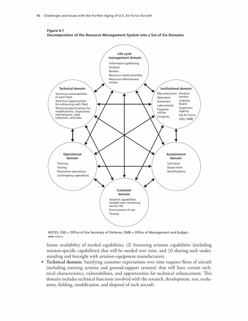
46 Challenges and Issues with the Further Aging of U.S. Air Force Aircraft
Figure 6.1Decomposition of the Resource Management System into a Set of Six Domains
NOTES: OSD = Office of the Secretary of Defense; OMB = Office of Management and Budget.RAND TR560-6.1
Technical domain
Technical vulnerabilitiesof each fleetTechnical opportunitiesfor enhancing each fleetTechnical specifications formodifications, inspections,maintenance, datacollection, and tests
Institutional domainManufacturersOperatorsSustainersLaboratoriesProgramofficesCongress
ProductcentersViabilityBoardInspectionAgencyHq Air ForceOSD, OMB
Operationaldomain
TrainingTestingPeacetime operationsContingency operations
Sustainmentdomain
Unit levelDepot levelModifications
Life-cycle management domain
Information-gatheringAnalysisReviewResource-needs prioritiesResource-effectivenessreview
Customerdomain
Aviation capabilitiesneeded over remainingservice lifeEnvironment of useThreats
future availability of needed capabilities, (2) foreseeing aviation capabilities (including mission-specific capabilities) that will be needed over time, and (3) sharing such under-standing and foresight with aviation-equipment manufacturers. Technical domain:• Satisfying customer expectations over time requires fleets of aircraft (including training systems and ground-support systems) that will have certain tech-nical characteristics, vulnerabilities, and opportunities for technical enhancement. This domain includes technical functions involved with the research, development, test, evalu-ation, fielding, modification, and disposal of such aircraft.
Finding the Right Pathway for Implementing Preferred Policy Options 47
Institutional domain:• The institutional domain includes functions that facilitate the interactions among domains and among workers within each domain. Such functions include the establishment and modifications of culture, policies, instructions, procedures, practices, arrangements, and contracts.Operational domain:• The operational domain includes functions involved with operat-ing a system of aircraft for the purpose of satisfying customer needs. It also includes func-tions related to recognition of equipment vulnerabilities, discrepancies, and deficiencies. Sustainment domain: • The sustainment domain includes such activities as those related to (1) keeping the aircraft functioning in a suitable manner and (2) effective recognition and resolution of technical vulnerabilities. Life-cycle-management domain:• This domain includes such functions as (1) effective resourcing of activities in all domains, (2) investment in the development of functional capacity in each domain, and (3) downsizing of functional capacity in each domain as that becomes appropriate.
Interdependencies Among Domains
Each circle in Figure 6.1 depicts one domain and gives some language about that domain that is related to this report’s interest in policy options for effective life-cycle management of resources. The lines between the domains are reminders of the interdependencies that often exist. Because such interdependencies can be expected to play significant roles in attempts to formulate and implement new policies, Figure 6.1 could be used as a planning tool during the policy-formulation phase.
Implementation of Preferred Policies Across Domains
The previous chapter focused on three policy areas: development of sustainment master plans, coordination of resource investments, and standardization in the way the Air Force establishes service-life goals. Policy initiatives in any of these areas are likely to touch on multiple domains in ways that depend on the cooperation and support of functions and people within those domains.
Formulation of Policy Initiatives. A well-formulated policy initiative will identify and incorporate provisions that facilitate necessary collaboration across all relevant domains. Figure 6.1 is an illustrative tool that can be helpful in beginning the process of identifying specific aspects of relevant domains.
Analysis of Prospective Value Added by Policy Initiatives. As alternative policy initiatives are considered, a question should arise regarding the prospective value that might be forthcom-ing from each alternative.
Opportunities to Add Value
Opportunities for policy initiatives to add value can be viewed in a couple of ways. The addition of value can be viewed from a domain perspective, as illustrated in the following examples:
Life-cycle-management domain:• The functions within this domain include informa-tion gathering, analysis, review, resource-needs prioritization, and resource-effectiveness review. Value-adding products from this domain could include (depending on manage-ment policies and resource-allocation policies) a remaining-life investment plan for each

48 Challenges and Issues with the Further Aging of U.S. Air Force Aircraft
fleet, a remaining-life sustainment master plan for each fleet, and the service-life goals for each fleet that are supported by closely coupled investment and sustainment plans.Sustainment domain:• The functions within this domain include specifying annual requirements for sustainment activities (over the remaining service lives) for unit-level maintenance, depot-level maintenance, and modifications. Value-adding products from this domain could include sufficiency review/analysis for satisfaction of sustainment requirements and independent audits of sufficiency reviews by systems engineers.Operational domain:• The functions within this domain include specifying annual requirements for operations (over remaining service lives) and for training, testing, peace-time operations, and contingency operations. Value-adding products from this domain could include sufficiency review/analysis for satisfaction of operational requirements and independent audits of sufficiency reviews by systems engineers.Institutional domain: • The functions within this domain include specifying annual requirements for institutional commitments (over remaining service lives). For critical interfaces, memoranda of understanding or interface control documents (ICD) could be used to formalize management of such interfaces.2 Value-adding products from this domain could include memoranda of agreement/ICDs for critical interfaces, sufficiency review/analysis for satisfaction of commitments,3 and independent audits4 of sufficiency reviews by systems engineers.Technical domain: • The functions within this domain include identifying the technical vulnerabilities of each fleet; identifying the technical opportunities for enhancing each fleet (over remaining service lives); and specifying the annual requirements for modifica-tions, inspections, maintenance, data collection, and tests (for remaining service lives). Value-adding products from this domain could include test reports, sufficiency review/analysis for satisfaction of commitments, and independent audits of sufficiency reviews by systems engineers.Customer domain:• The functions within this domain include defining aviation capa-bilities needed over each fleet’s remaining service life, defining environment of use (for remaining service lives), and defining threats (over remaining service lives). Value-adding products from this domain could include the availability of aircraft when needed, trust-worthiness when used, and cost-effectiveness in the use of resources.
Observation of Value
Observations of value being added by investments of resources in the performance of work are fundamental to effective life-cycle management of resources.
2 The ability of the ASIP approach to managing damage tolerance in airframe structures depends on the completeness and accuracy of documentation about the actual use of each individual aircraft. Using an MOA/ICD to provide formal management of the usage-tracking interface between operations and engineering could help ensure high levels of sustained excellence for such a critically important interface. Using the systems-engineering practice of a formal ICD to help manage an interface, such as the usage-tracking interface, creates a documentation trail for an agreed-on baseline outlining what was supposed to have been done by whom and when. Such a documented baseline for an interface can contribute to good order and discipline and can be invaluable in diagnosing the causes of any deviations from the baseline expectations of performance.3 Review/analysis of the sufficiency of products can provide a way to catch and correct problems early.4 Auditing the completion of tasks can help keep systems engineers apprised of the sufficiency and quality of the system-related efforts.
Finding the Right Pathway for Implementing Preferred Policy Options 49
In theory, observation of value at the customer level can be done over an aircraft’s remain-ing life in terms of observed
readiness when needed•trustworthiness when used•cost-effectiveness in the application of resources.•
Value also can be observed at a technical level in terms of sound systems characteristics that can be observed early in an aircraft’s life cycle. Such values can include
aircraft that perform well•aircraft that are maintainable, reparable, and modifiable•aircraft that are cost-effective over their service lives to date•extrapolation of historical cost trends predicting that the aircraft will remain cost- •effective for the duration of their currently planned service life.
Value also can be observed at the process/practice level in terms of management and engi-neering practices that include
flight tests, cyclic fatigue tests, and usage-tracking programs that provide engineering •substantiation for service-life goals and remaining-life maintenance and modification programsexplicit and current investment plans for remaining lives •sustainment master plans that are thorough and current•service-life goals that are well founded and linked to investment and sustainment plans•sufficiency reviews that are thorough and complete and accomplished by an independent •partyaudits of sufficiency reviews that are objective and current and accomplished by an inde-•pendent party.
Sound management and engineering practices combined with sound system characteris-tics can create circumstances favorable to providing the best opportunity for delivering endur-ing customer value over each aircraft’s remaining life.
Finding the Right Pathway for Enhancing the Resource-Management System
Given the foregoing assessments of challenges (Chapters Three and Four) and issues (Chapter Five) and given this report’s concepts that might be applied to addressing the identified chal-lenges and resolving the identified issues, would it be worthwhile to embark an a pathway toward enhancing the resource-management system? And, if so, what pathway might offer the most promise? To address these questions, a set of policy options was developed (see the appen-dix) and an approach to evaluating alternative policy initiatives was developed and is described in this chapter.
50 Challenges and Issues with the Further Aging of U.S. Air Force Aircraft
Testing and Evaluating a Prototype Pathway
To gather additional information about the potential costs and benefits of alternative path-ways, an exploratory prototype could be designed, tested, and evaluated.
An Exploratory Prototype
Assume that a major command for a particular mission area is exploring whether it is cost ben-eficial to implement a set of policy initiatives as a prototype test. Furthermore, assume that the command has concerns about an important fleet and would like to know more about its real prospects for satisfying what may be an ambitious goal for its service life. For such a situation, consider a multiphase prototype that would progress as justified.
The initial phase would make maximum use of available information to construct initial drafts for (1) a master plan for those sustainment activities foreseeable over the fleet’s remain-ing service life, (2) an investment plan for providing necessary resources for such sustainment activities, and (3) the technical basis for the current service-life goal.
A Test and Evaluation Plan
At the end of each phase, the value added by the prototype would be evaluated in the way previously described. The scope for any follow-on phase would be determined after such an evaluation.
51
CHAPTER SEVEN
Conclusions
Cost-effectively sustaining a fleet of aging aircraft requires that an operator accomplish two objectives: (1) make the right investments in aircraft sustainment and (2) make the right deci-sion about when to replace the aircraft. Although getting it right can allow a user to defer replacement costs, getting it wrong can ultimately cost more, yield less capability, and disrupt capacity to complete important missions. On the one hand, sustaining use far beyond an aircraft’s design service life may allow an operator to conserve significant resources. On the other hand, there always will be uncertainties associated with aging mechanisms and about the consequences of errors in estimates of longevity and future costs. Thus, an important role of sustainment processes is to help operators conserve resources while protecting their essential interests from surprises.
As the cost of sustaining aging systems continues to rise, and as the competition for scarce resources continues, getting each aircraft’s sustainment road map right will become increas-ingly important to controlling sustainment costs and protecting the operator from disruptions caused by unanticipated sustainment problems. This report aims to help operators do this by providing a new way to think about policy options for effective life-cycle management of resources for the further aging of already-old aircraft.
The new approach addresses the technical and institutional challenges of aging and the associated issues related to managing resources by using a total-systems paradigm that breaks a resource-management system into its principal domains to analyze how major challenges and issues relate to values that are important within each domain and to the customer. Connec-tions to such a value structure can help decisionmakers set policy priorities for enhancing the resource-management system that must deal with the further aging of already-old aircraft.


53
APPENDIX
Policy Options for Addressing Challenges and Issues
This appendix describes some specific policy options that would provide ways to implement initiatives responsive to the challenges and issues identified in this report.
Sustainment Master Plans for Remaining Lives of Fleets
The following policy options address several aspects of implementing a sustainment-master-planning (SMP) approach.
SMP Vision
Consider a vision for a fleet’s SMP, such as a living document that contributes to readiness, trustworthiness, and cost-effectiveness throughout each fleet’s remaining life.
SMP Mission
Consider a mission for a sustainment master plan, such as one in which users, sustainers, and others continuously develop knowledge and plans that assure readiness, trustworthiness, and cost-effectiveness throughout a fleet’s remaining life.
SMP Objectives
To accomplish its mission, consider requiring that each fleet’s SMP achieve the following objectives:
Ready:• The plan is ready when needed to guide sustainment processes. This means that it not only is available but it also is current. Trustworthy:• The plan earns the trust of the participants in the sustainment and resource-allocation processes by being complete, accurate, and objective.Cost-effective:• The plan is cost-effective both in its development and updating as well as in its execution over time. This means that it focuses on the most significant mission-relevant matters. It also means that it identifies areas where enhancements of processes and knowledge may yield worthwhile advances.
SMP Content
To accomplish its mission objectives, consider including the following in the SMP:
Operational requirements:• fleet size and required capabilities over time
54 Challenges and Issues with the Further Aging of U.S. Air Force Aircraft
baseline requirement –sensitivity of the baseline to investments in capabilities –sensitivity of the baseline to threat and employment scenarios –
Service-life goal:• current service-life goal and its justificationbaseline goal –sensitivity of the baseline goal to investments in sustainment –sensitivity of the baseline goal to accepted level of risk –
Statement of required actions:• actions required (including milestones and costs) to satisfy the operational requirements and achieve the service-life goal, including
limitations on use –maintenance requirements including inspections and repairs –modifications –process enhancements –advances in technology –
SMP limit of validity:• consider establishing a limit of validity, such as an expiration limit (e.g., expressed in flight hours), for an SMP. Consider using an independent-assessment process to determine such limits. Consider using a process that includes
evaluation of the SMP by an independent authority –establishment of a limit of validity by an independent authority –a blue-ribbon review of an independent authority’s determination of a limit of –validity.
SMP Technical Support
Consider establishing an independent engineering organization to provide technical support for sustainment assessments, including reviews of any limits of validity established for SMPs.
Coordinated Investments in Remaining-Life Sustainment
The following policy options address several aspects of implementation for a more coordinated approach to investments in the sustainment of the remaining lives of fleets.1
Coordinating Interdependent Activities by Different Parties
Consider requiring coordination such as
across sustainment activities•between sustainment activities and research and development activities•between sustainment activities and operations•among operators, sustainment program offices, and resource allocation processes•
1 Because many different categories of funds are involved in the sustainment of an aircraft weapon system, and because many different projects are authorized and funded to varying extents, the current approach can produce a set of budget decisions that omit or underfund activities that are very important over the long term.
Policy Options for Addressing Challenges and issues 55
between the establishment of service-life goals and decisions about the allocation of •resourcesacross fleets within a mission area•across mission areas.•
Fleet Size and Required Capabilities over Time
Consider requiring that both using and sustainment organizations collaborate in developing and annually updating a baseline remaining-life plan for the modification and use of each fleet.
Using organizations:• Consider having using organizations develop and annually update their remaining-life plans including the size of the fleet they need and its capabilities over time. Sustaining organizations:• Consider having these organizations provide the using organi-zations with annual assessments of such technical, cost, and risk information that using organizations may need to make informed judgments regarding fleet size and capabilities over time.
Service-Life Goal and Justification
Consider involving using and sustaining organizations in the process of establishing a service-life goal for a fleet.
Using organizations:• Consider having the using organizations provide to the sustaining organization:
a preference for the fleet’s service-life goal –the level and composition of sustainment investments that it is prepared to support –vigorously through the resource-allocation process the level of risk that it is prepared to accept –
Sustaining organizations:• Consider having these organizations provide using organiza-tions with such technical, cost, and risk information that may be needed to make and justify informed decisions about sustainment investments, a level of acceptable risk, and the fleet’s service-life goal.
Methodology for Establishing Meaningful Service-Life Goals
The following policy options address several aspects of implementing a standardized method-ology for establishing service-life goals.
Standard Approach
Consider creating a standard approach for establishing meaningful service-life goals, to include
56 Challenges and Issues with the Further Aging of U.S. Air Force Aircraft
Technical knowledge:• (a) current status of the fleet; (b) aging processes that will affect future conditions and needs over time and an understanding of the nature and extent of such effects; and (c) opportunities to mitigate future conditions and needs over time and the likely costs, benefits, and risks attributable to each mitigation opportunityCoherent, comprehensive plan (CCP):• (a) users’ plans for future operations, (b) an SMP, and (c) a coordinated investment planInstitutional commitment:• decisions over time that comply with the CCPMeaningful measures of fleet conditions, and compliance with CCP:• (a) related to criti-cal aging factors, (b) measurable, and (c) measured at prescribed intervalsFull and transparent monitoring and analysis of the meaningful measures:• Provides insight regarding (a) progression of aging processes, (b) relevancy of past technical and economic forecasts on which current planning has been based, and (c) extent of organi-zational compliance with institutional commitmentsEvidence-based adaptation of plans:• This includes all necessary adjustments that are war-ranted by new knowledge of changing conditions and circumstances.
Establishment of Limits on Use That May Be Required to Realize a Service-Life Goal
To realize effective life-cycle management of resources, consider requiring that service-life goals consider potential limitations on future use or changes in prevailing practices that may make it difficult to realize a service-life goal.
Using organizations:• Consider requiring that using organizations identify anticipated changes over time to limitations on use or changes in past practices that may influence realization of a service-life goal. Sustaining organizations:• Consider requiring that sustaining organizations provide the using organizations with (1) information about the influence of changes in use on the realization of a service-life goal; and (2) related technical evidence, including tests, experi-ence, technical reports, and independent reviews.
Certification of Capacity to Perform Remaining-Life Planning
To realize effective life-cycle management of resources, consider requiring certification of the capacity to perform remaining-life planning for modifications and maintenance (including inspection and repair) activities that would be needed to realize a service-life goal.
Using organizations:• Consider requiring that an independent authority certify the using organization’s capacity to perform the following tasks:
use information provided by the sustaining organizations and an independent engi- –neering organization to establish the level and nature of modifications that will be required use information provided by the sustaining organizations and an independent engi- –neering organization to establish the level and nature of maintenance that will be required

Policy Options for Addressing Challenges and issues 57
Sustaining organizations:• For the service-life goal and the level of acceptable risk selected by the using organizations, consider requiring that an independent authority certify the sustaining organizations’ capacity to perform the following tasks:
provide the using organizations with a recommended, comprehensive maintenance –plan for all modification and maintenance work to be performed during the fleet’s remaining lifeprovide the using organizations with an analysis of how the comprehensive modifica- –tion and maintenance plan should change as a function of alternative levels of invest-ment in sustainment and alternative levels of assumed riskengage an independent engineering organization to perform a remaining-life risk –assessment for each combination of level of investment in sustainment and accepted risk considered in the SMP.
Identification of Process Enhancements That May Be Required to Realize a Service-Life Goal
To realize effective life-cycle management of resources, consider requiring that the analysis of service-life goals include evaluations of process enhancements that may be necessary to develop, monitor, and realize meaningful service-life goals.
Identification of Any Advancements in Technology That May Be Required to Realize a Service-Life Goal
To realize effective life-cycle management of resources, consider requiring that the analysis of service-life goals include evaluations of any advancement in technology that may be necessary to develop, monitor, and realize a proposed service-life goal. For example, a proposed service-life goal may depend on advances in inspection technology.

59
Bibliography
Air Force Instruction 63-1001, Aircraft Structural Integrity Program, April 18, 2002.
Air Force Policy Directive, 63-10, Aircraft Structural Integrity Program, November 1, 1997.
Air Force Space and Missile Systems Center, Systems Engineering Primer and Handbook: Concepts, Processes, and Techniques, El Segundo, Calif.: Los Angeles Air Force Base, 2004.
Barker, Joel Arthur, Paradigms, The Business of Discovering the Future, New York: Harper Collins, 1993.
Baum, Claude, The System Builders: The Story of SDC, Santa Monica, Calif.: System Development Corporation, 1981.
Beard, Edmund, Developing the ICBM, New York: Columbia University Press, 1976.
Blanchard, Benjamin S., and Wolter J. Fabrycky, Systems Engineering and Analysis, Upper Saddle River, N.J.: Prentice Hall, 1998.
Buede, Dennis M., The Engineering Design of Systems, Models and Methods, New York: Wiley, 2000.
Butkus, Larry M., Joseph P. Gallagher, and Charles A. Babish, “The U.S. Air Force’s Aircraft Structural Integrity Program (ASIP),” Proceedings of the 2006 International Fatigue Congress, Atlanta, Ga., May 14–19, 2006.
Coffin, M. D., and Charles F. Tiffany, “New Air Force Requirements for Structural Safety, Durability, and Life Management,” Journal of Aircraft, Vol. 13, No. 2, February 1976, pp. 93–98.
Committee on Aging of U.S. Air Force Aircraft, Commission on Engineering and Technical Systems, National Research Council, Aging of U.S. Air Force Aircraft: Final Report, Washington, D.C.: National Academies Press, 1997.
Defense Science Board, Corrosion Control, Washington, D.C., October 2004.
Defense Systems Management College, Systems Engineering Fundamentals, Fort Belvoir, Va.: Defense Acquisition University Press, January 2001.
Duncan, Francis, Rickover and the Nuclear Navy, The Discipline of Technology, Annapolis, Md.: Naval Institute Press, 1990.
Eastin, Robert G., and John W. Bristow, “Looking at Lusaka’s Lessons,” Proceedings of the 2003 USAF Aircraft Structural Integrity Program Conference, Savannah, Ga., December 2–4, 2003.
Forman, Royce G., “Early History and Current Development Efforts in Fracture Mechanics Applications for Aircraft,” 2002 USAF Aircraft Structural Integrity Program Conference, Savannah, Ga., December 10–12, 2002.
Gallagher, Joseph P., “A Review of Philosophies, Processes, Methods and Approaches That Protect In-Service Aircraft from the Scourge of Fatigue Failures,” Proceedings of the 24th ICAF Symposium, Naples, Italy, May 16–18, 2007.
Gebman, Jean R., Opportunities for Systems Engineering to Contribute to Durability and Damage Tolerance of Hybrid Structures for Airframes, Santa Monica, Calif.: RAND Corporation, TR-489-AF, 2008. As of July 28, 2008: http://www.rand.org/pubs/technical_reports/TR489
60 Challenges and Issues with the Further Aging of U.S. Air Force Aircraft
Gebman, Jean R., and Paul C. Paris, Probability That the Propagation of an Undetected Fatigue Crack Will Not Cause a Structural Failure, Santa Monica, Calif.: RAND Corporation, R-2238-RC, 1978. As of August 1, 2007: http://www.rand.org/pubs/reports/R2238/
———, “Probability That the Propagation of an Undetected Fatigue Crack Will Not Cause a Structural Failure,” Fatigue Crack Growth Measurement and Analysis, American Society for Testing and Materials, STP-738, 1979.
Goranson, Ulf G., “Damage Tolerance Facts and Fiction,” Lincoln Award Lecture, 2006 Conference of USAF Aircraft Structural Integrity Program, San Antonio, Tex., November 28–30, 2006; also 14th Plantema Memorial Lecture presented at the 17th Symposium of the International Committee on Aeronautical Fatigue, Stockholm, Sweden, June 9, 1993.
Government Electronics and Information Technology Association (GEITA), Processes for Engineering a System, ANSI/GEIA EIA-632, September 2003.
Hahn, Gail, “Accelerated Insertion of Materials—Composites: A Technology Investment Agreement,” presentation at the MMS-OTRC Workshop: Qualifying New Technology for Deepwater Oil and Gas Development, Orlando, Fla., October 29, 2002a.
———, “Accelerated Insertion of Materials—Impact of Manufacturing on Performance,” presentation at the MMS-OTRC Workshop: Qualifying New Technology for Deepwater Oil and Gas Development, Orlando, Fla., October 29, 2002b.
Institute of Electrical and Electronics Engineers, Standard for Application and Management of the System Engineering Process, IEEE Standard 1220-1998, New York, 1998.
International Council of Systems Engineers, Systems Engineering Handbook, Seattle, Wash., July 2000.
Kim, Yool, Stephen Sheehy, and Darryl Lenhardt, A Survey of Aircraft Structural-Life Management Programs in the U.S. Navy, the Canadian Forces, and the U.S. Air Force, Santa Monica, Calif.: RAND Corporation, MG-370-AF, 2006. As of August 1, 2007: http://www.rand.org/pubs/monographs/MG370/
Lincoln, John W., “Aging Aircraft Issues in the United States Air Force,” SAMPE Journal, Vol. 32, No. 5, 1996, pp. 27–33.
———, Risk Assessments of Aging Aircraft, Ogden, Utah: DoD/FAA/NASA Conference on Aging Aircraft, July 8–10, 1997.
Maier, Mark W., and Eberhardt Rechtin, The Art of Systems Architecting, Washington, D.C.: CRC Press, 2000.
MIL-HDBK—See Military Handbook.
MIL-STD—See Military Standard.
Military Handbook 17/1F, Composite Materials Handbook, Vol. 1, Polymer Matrix Composites Guidelines for Characterization of Structural Materials, 2002.
———, 17/2F, Composite Materials Handbook, Vol. 2, Polymer Matrix Composites Materials Properties, 2002.
———, 17/3F, Composite Materials Handbook, Vol. 3, Polymer Matrix Composites Materials Usage, Design, and Analysis, 2002.
———, 17/4A, Composite Materials Handbook, Vol. 4, Metal Matrix Composites, 2002.
———, 17/5, Composite Materials Handbook, Vol. 5, Ceramic Matrix Composites, 2002.
Military Standard 1530C, Department of Defense Standard Practice: Aircraft Structural Integrity Program (ASIP), Washington, D.C.: U.S. Air Force, November 1, 2005.
National Aeronautics and Space Administration, Systems Engineering Handbook, SP-610S, Washington, D.C., June 1995.
National Research Council, Aging of U.S. Air Force Aircraft, National Materials Advisory Board, Washington, D.C.: National Academy Press, NMAB-488-2, 1997.
Bibliography 61
National Transportation Safety Board, Metallurgist’s Factual Report, Aircraft Accident Report, Aloha Airlines, Flight 243, Boeing 737-200, N73711, Near Maui, Hawaii, April 28, 1988, Washington, D.C., June 22, 1988a.
———, Metallurgist’s Factual Report, Aircraft Accident Report, Aloha Airlines, Flight 243, Boeing 737-200, N73711, Near Maui, Hawaii, April 28, 1988, Washington, D.C., August 17, 1988b.
———, Aircraft Accident Report, Aloha Airlines, Flight 243, Boeing 737-200, N73711, Near Maui, Hawaii, April 28, 1988, NTSB/AAR-89-03, Washington, D.C., 1989.
———, Photographs of Aloha Flight 243, supplied by Hawaiian Steam Engineering Company, Washington, D.C., 2002.
———, In-Flight Separation of Vertical Stabilizer, American Airlines Flight 587, Airbus Industrie A300-605R, N14053, Belle Harbor, New York, November 12, 2001, AAR-04/04, PB2004-910404, Washington, D.C., 2004.
Nieser, Donald E., “Effects of Corrosion on C/KC-135 Structural Life and Flight Safety to 2040,” Proceedings of the Fourth Joint DoD/FAA/NASA Conference on Aging Aircraft, St. Louis, Mo., May 15–18, 2000.
———, Photographs of Exhibits Depicting Corrosion of KC-135 Parts, provided to RAND staff, 2001.
Paris, Paul C., “The Fracture Mechanics Approach to Fatigue,” in J. J. Burke, N. L. Reed, and V. Weiss, eds., Fatigue—An Interdisciplinary Approach, Syracuse, N.Y.: Syracuse University Press, 1964, pp. 107–132.
Paris, Paul C., M. Gomez, and W. Anderson, “A Rational-Analytic Theory of Fatigue,” The Trend in Engineering, Seattle, Wash.: University of Washington, Seattle, 1961.
Porter, William A., Modern Foundation of System Engineering, New York: Macmillan, 1968.
Rickover, Hyman, Admiral, U.S. Navy, Director, Naval Nuclear Propulsion Program, statement before the House Subcommittee on Energy and Propulsion, Washington, D.C., May 1979.
Rockwell, Theodore, The Rickover Effect, How One Man Made a Difference, Annapolis, Md.: Naval Institute Press, 1992.
Rouse, William B., and Kenneth R. Boff, “Value-Centered R&D Organizations: Ten Principles for Characterizing, Assessing, and Managing Value,” System Engineering, Vol. 7, No. 2, Hoboken, N.J.: Wiley, 2004, pp. 167–185.
Sage, Andrew P., Systems Engineering: Methodology and Applications, New York: IEEE Press, 1977.
Sage, Andrew P., and James A. Melsa, System Identification, New York: Academic Press, 1971.
Sapolsky, Harvey M., The Polaris System Development, Cambridge, Mass.: Harvard University Press, 1972.
Schutz, Walter, “A History of Fatigue,” Engineering Fracture Mechanics, Vol. 54, No, 2, Great Britain: Elsevier, 1996, pp. 263–300.
Schwartz, Peter, The Art of the Long View, New York: Doubleday, 1991.
Taormina, Tom, Virtual Leadership and the ISO 9000 Imperative, Upper Saddle River, N.J.: Prentice Hall, 1996.
U.S. Air Force, KC-X Request for Proposal, Contract Data Requirements List, Washington, D.C., January 2007.
U.S. Department of Defense, Systems Engineering Plan (SEP), Preparation Guide, Washington, D.C., February 10, 2006.
U.S. Department of Transportation, Federal Aviation Administration, “Conducting Records Reviews and Aircraft Inspections Mandated by the Aging Aircraft Rules,” Notice 8300.113, Washington, D.C., November 25, 2003.