Embed Size (px)
Citation preview
INTERNATIONAL JOURNAL OF CIRCUIT THEORY AND APPLICATIONS
Int. J. Circ. ¹heor. Appl., 27, 5—23 (1999)
THE ART OF CNN TEMPLATE DESIGN
AKOS ZARANDY
Computer and Automation Institute of the Hungarian Academy of Science, (MTA-SzTAKI), 11. La& gyma& nyosi u& t, Budapest,H-1111, Hungary
SUMMARY
A practical survey of the design rules of uncoupled and coupled linear CNN templates with binary inputs and outputs isgiven. The usage and the properties of the different classes of CNN templates are analysed. CNN chip specific robustnessconsiderations are also given. Copyright ( 1999 John Wiley & Sons, Ltd.
KEY WORDS: CNN; CNN template design; robustness
1. INTRODUCTION
A cellular neural network (CNN)1,2 is a locally interconnected analogue processor array arranged toa regular 2D grid. Its two-dimensional inputs and output makes it extremely suitable for image processing.Due to its regular (in most cases rectangular) arrangement and its local interactions, programmable CNN(the so-called CNN Universal Machine3) can be efficiently implemented on silicon. With today’s availabledeep submicron technology (0)33—0)25 lm) 64]64 or up to 100]100 large analogue processor arrays can beimplemented on a single chip. Some smaller operational test chips are already available.5—7 The spatial-temporal transient of an analog VLSI CNN array settles down in the 100 ns range. This means, that an imageprocessing primitive (like edge detection, blurring, sharpening, thresholding, etc.) can be calculated fora 64]64 (or 100]100) pixel sized image in less than a microsecond with a single chip. In the digital word thisincredible huge computational power is equivalent with Tera (1012) operations per second,4 which is thesame as the total computational power of a supercomputer containing &9000 pieces of Pentium 200 MHz.But while programming a digital microprocessor is relatively easy, here one has to find the exact parameterset of a continuous time spatial-temporal non-linear array dynamic to force it to calculate an imageprocessing primitive. Since CNN has a space invariant local interconnection structure it has 19 freeparameters only. This parameter set, called template, exclusively determines its array’s dynamic behaviour.This paper surveys the design methods of the different templates.
There are three major template design methods: (i) intuitive way, (ii) template learning, and (iii) directtemplate derivation. The first requires intuitive thinking of the designer. In several simple cases it leads toquick results. However, it does not guarantee to find the desired template. Moreover, designers need to havelots of experiments in both the image processing and the array dynamics.
The second design method, the template learning, is an extensively studied, popular field of the CNNresearch. Almost all classical neural network training methods have been applied to the CNN structure. Butthere are three serious problems with these techniques and results. First of all, the learning is based on inputand desired output pairs, and during the learning procedure better-and-better results are supposed to begenerated with better-and-better templates. But in many cases (especially, propagating-type templates likeCCD8) the template either works or does not work, and there are no subsequent better-and-better resultseries. This might change the strategy of a learning method to a brute-force method. The second problem is
Correspondence to: A. Zarandy, Computer and Automation Institute of the Hungarian Academy of Science, (MTA-SzTAKI), 11.Lagymanyosi ut, Budapest, H-1111, Hungary. Email: [email protected]
CCC 0098—9886/99/010005—19$17.50 Received 15 May 1997Copyright ( 1999 John Wiley & Sons, Ltd. Revised 17 November 1997
that in some cases template for the given problem does not exist. The learning methods cannot even realize it,and they run forever. If the template exists, it might take a long time to find it, if it can at all. The thirdproblem is that several proposed learning methods were tested and proved to be efficient to those templategroups, which can be directly derived from the exact function descriptions. In these cases it is unnecessary touse learning methods. However, there are some cases when the template learning is a very important designmethod. In those cases, where no explicit desired output exists, the direct template design is impossible.Texture segmentation is a good example for this case.9
The third method, considered in this paper, is the direct template design. It can be applied when the desiredfunction is exactly determined. The design methods depend on the particular template class. While theprevious two methods produced a single or a few working templates, here we get all of them. This providesthe opportunity to choose the best, the most robust template among them. Moreover, this method needs onlya small fraction of the computational power the template learning needs.
Here, we give a survey of the design and the usage of the different template classes. For each class first, wedescribe the basic properties of the network. Then, we survey the typical problems, which can be solved usingtemplates from the particular class. After this we discuss the template design method and show some designexamples. Finally, a CNN chip implementation specific robustness analysis and other important notes aregiven. The structure of the paper is the following: in Section 2 the uncoupled templates, while in Section 3 thecoupled templates are discussed. Some templates, mentioned in this paper, are described in the appendix.
Our main goal with this paper is to give a practical introduction of the template design. Instead of strictlyproving all of our statements, we rather show some tricks and interesting useful solutions. Some parts of thispaper (like the binary uncoupled template design was already discussed in different forms.10—13 Here, we givea summary, and show some practical examples. Other parts, like the coupled binary CNN template designare new results. All template design methods, presented in this paper, can be used in both the Chua—½angmodel1 and the full signal range (FSR) model.14 In case of the FSR model the centre element of the derivedtemplate should be decreased with unity.
2. UNCOUPLED CNN TEMPLATES
Uncoupled templates have zero off-centre A template elements only. The general form of the uncoupledtemplates is the following:
A"C0 0 0
0 a00
0
0 0 0D , B"Cb~1~1
b~10
b~11
b0~1
b00
b01
b1~1
b10
b11D , z"i (1)
Since their dynamic parts are uncoupled, they work as an array of independent first-order elements (cells).Hence, it is satisfactory to analyse the dynamic behaviour of a single cell. A single cell receives nine staticinputs from the input layer (u
kl). It has an initial condition x (0), which can be considered as a tenth input. An
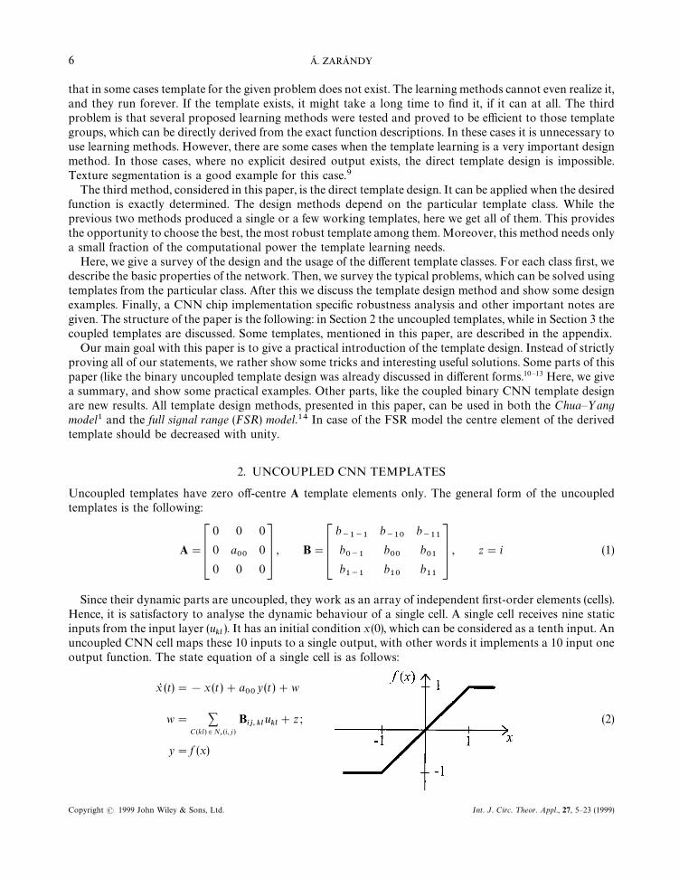
uncoupled CNN cell maps these 10 inputs to a single output, with other words it implements a 10 input oneoutput function. The state equation of a single cell is as follows:
xR (t)"!x (t)#a00
y (t)#w
w" +C(kl )3N
r(i, j )
Bij, kl
ukl#z ; (2)
y"f (x)
6 A. ZARANDY
Copyright ( 1999 John Wiley & Sons, Ltd. Int. J. Circ. ¹heor. Appl., 27, 5—23 (1999)
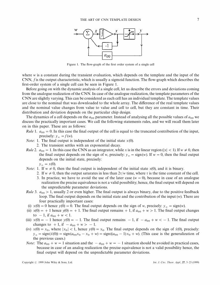
Figure 1. The flow-graph of the first order system of a single cell
where w is a constant during the transient evaluation, which depends on the template and the input of theCNN, f is the output characteristic, which is usually a sigmoid function. The flow-graph which describes thefirst-order system of a single cell can be seen in Figure 1.
Before going on with the dynamic analysis of a single cell, let us describe the errors and deviations comingfrom the analogue realization of the CNN. In case of the analogue realization, the template parameters of theCNN are slightly varying. This can be considered as each cell has an individual template. The template valuesare close to the nominal that was downloaded to the whole array. The difference of the real template valuesand the nominal value changes from value to value and cell to cell, but they are constant in time. Theirdistribution and deviation depends on the particular chip design.
The dynamics of a cell depends on the a00
parameter. Instead of analysing all the possible values of a00
wediscuss the practically important cases. We call the following statements rules, and we will recall them lateron in this paper. These are as follows:
Rule 1. a00"0. In this case the final output of the cell is equal to the truncated contribution of the input,
precisely: y="f (w).
Note: 1. The final output is independent of the initial state x (0).2. The transient settles with an exponential decay.
Rule 2. a00"1. In this case the CNN as an integrator, while x is in the linear region (DxD(1). If wO0, then
the final output depends on the sign of w, precisely: y="sign (w). If w"0, then the final output
depends on the initial state, precisely:y="x (0).
Note: 1. If wO0, then the final output is independent of the initial state x(0), and it is binary.2. If wO0, then the output saturates in less than 2q/w time, where q is the time constant of the cell.3. In practice, we have to avoid the use of the later case (w"0), because in case of an analogue
realization the precise equivalence is not a valid possibility; hence, the final output will depend onthe unpredictable parameter deviations.
Rule 3. a00'1, usually 2 or even higher. The final output is always binary, due to the positive feedback
loop. The final output depends on the initial state and the contribution of the input (w). There arefour practically important cases:
(i) x (0)"0 hence y(0)"0. The final output depends on the sign of w, precisely: y="sign(w).
(ii) x(0)"#1 hence y(0)"#1. The final output remains#1, if a00#w'1. The final output changes
to !1, if a00#w(1.
(iii) x (0)"!1 hence y (0)"!1. The final output remains !1, if !a00#w(!1. The final output
changes to #1, if !a00#w'!1.
(iv) x(0)"x0, where Dx
0D(1, hence y(0)"x
0. The final output depends on the sign of xR (0), precisely:
y="sign (xR (0))"sign (a
00x0!x
0#w)"sign ((a
00!1)x
0#w). (This case is the generalization of
the previous cases.)Note: The a
00#w"1 situation and the !a
00#w"!1 situation should be avoided in practical cases,
because in case of an analog realization the precise equivalence is not a valid possibility hence, thefinal output will depend on the unpredictable parameter deviations.
THE ART OF CNN TEMPLATE DESIGN 7
Copyright ( 1999 John Wiley & Sons, Ltd. Int. J. Circ. ¹heor. Appl., 27, 5—23 (1999)
These rules can be trivially derived from the state equation (2) and the flow-graph (Figure 1) of a singleCNN cell. After analysing the dynamic of a single cell, here we go through the four elementary uncoupledCNN template classes. In the following part of the paper the inputs and the outputs of the CNN will bemanifested in image forms. We follow the original convention of Reference 1, where #1 stands for black, and!1 stands for white, and the intermediate values are represented by different gray shades.
2.1. Binary input—binary output uncoupled CNN templates
The uncoupled binary CNN templates form a very important class, because it covers the binary imagealgebra or binary mathematical morphology which is a well known and a frequently used tool-kit of the imageprocessing. We grouped the most important templates into three classes. Here, we show these groups andillustrate them with examples, list the template names from the Template Library8 belonging to the eachgroup, and introduce the design method.
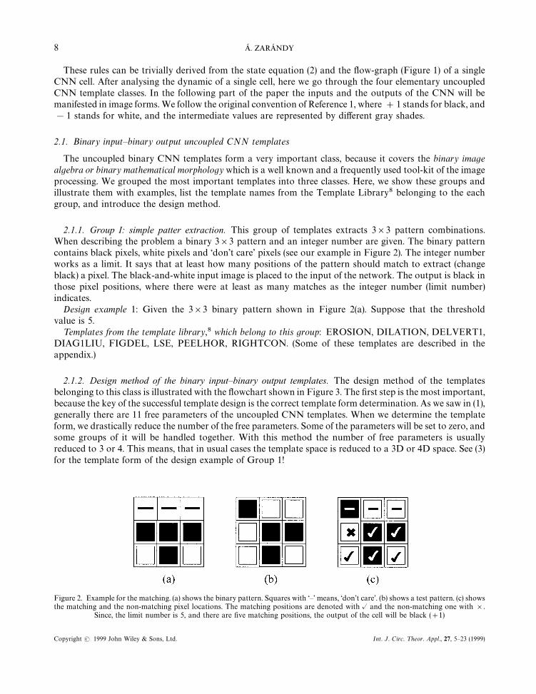
2.1.1. Group I: simple patter extraction. This group of templates extracts 3]3 pattern combinations.When describing the problem a binary 3]3 pattern and an integer number are given. The binary patterncontains black pixels, white pixels and ‘don’t care’ pixels (see our example in Figure 2). The integer numberworks as a limit. It says that at least how many positions of the pattern should match to extract (changeblack) a pixel. The black-and-white input image is placed to the input of the network. The output is black inthose pixel positions, where there were at least as many matches as the integer number (limit number)indicates.
Design example 1: Given the 3]3 binary pattern shown in Figure 2(a). Suppose that the thresholdvalue is 5.
¹emplates from the template library,8 which belong to this group: EROSION, DILATION, DELVERT1,DIAG1LIU, FIGDEL, LSE, PEELHOR, RIGHTCON. (Some of these templates are described in theappendix.)
2.1.2. Design method of the binary input—binary output templates. The design method of the templatesbelonging to this class is illustrated with the flowchart shown in Figure 3. The first step is the most important,because the key of the successful template design is the correct template form determination. As we saw in (1),generally there are 11 free parameters of the uncoupled CNN templates. When we determine the templateform, we drastically reduce the number of the free parameters. Some of the parameters will be set to zero, andsome groups of it will be handled together. With this method the number of free parameters is usuallyreduced to 3 or 4. This means, that in usual cases the template space is reduced to a 3D or 4D space. See (3)for the template form of the design example of Group 1!
Figure 2. Example for the matching. (a) shows the binary pattern. Squares with ‘—’ means, ‘don’t care’. (b) shows a test pattern. (c) showsthe matching and the non-matching pixel locations. The matching positions are denoted with @ and the non-matching one with ].
Since, the limit number is 5, and there are five matching positions, the output of the cell will be black (#1)
8 A. ZARANDY
Copyright ( 1999 John Wiley & Sons, Ltd. Int. J. Circ. ¹heor. Appl., 27, 5—23 (1999)
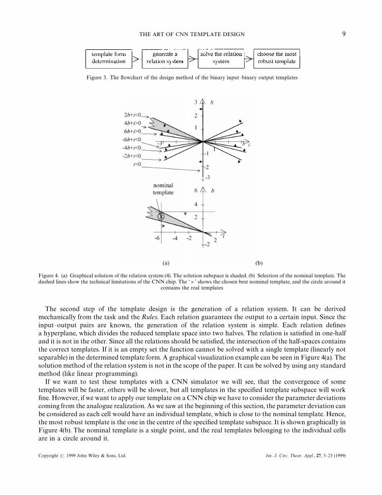
Figure 3. The flowchart of the design method of the binary input—binary output templates
Figure 4. (a) Graphical solution of the relation system (4). The solution subspace is shaded. (b) Selection of the nominal template. Thedashed lines show the technical limitations of the CNN chip. The ‘]’ shows the chosen best nominal template, and the circle around it
contains the real templates
The second step of the template design is the generation of a relation system. It can be derivedmechanically from the task and the Rules. Each relation guarantees the output to a certain input. Since theinput—output pairs are known, the generation of the relation system is simple. Each relation definesa hyperplane, which divides the reduced template space into two halves. The relation is satisfied in one-halfand it is not in the other. Since all the relations should be satisfied, the intersection of the half-spaces containsthe correct templates. If it is an empty set the function cannot be solved with a single template (linearly notseparable) in the determined template form. A graphical visualization example can be seen in Figure 4(a). Thesolution method of the relation system is not in the scope of the paper. It can be solved by using any standardmethod (like linear programming).
If we want to test these templates with a CNN simulator we will see, that the convergence of sometemplates will be faster, others will be slower, but all templates in the specified template subspace will workfine. However, if we want to apply our template on a CNN chip we have to consider the parameter deviationscoming from the analogue realization. As we saw at the beginning of this section, the parameter deviation canbe considered as each cell would have an individual template, which is close to the nominal template. Hence,the most robust template is the one in the centre of the specified template subspace. It is shown graphically inFigure 4(b). The nominal template is a single point, and the real templates belonging to the individual cellsare in a circle around it.
THE ART OF CNN TEMPLATE DESIGN 9
Copyright ( 1999 John Wiley & Sons, Ltd. Int. J. Circ. ¹heor. Appl., 27, 5—23 (1999)
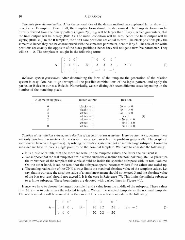
¹emplate form determination: After the general idea of the design method was explained let us show it inpractice on Example I. First of all, the template form should be determined. The template form can bedirectly derived from the binary pattern (Figure 2(a)). a
00will be larger than 1 (say 2) which guarantees, that
the final output will be binary (Rule 3.). The initial condition will be zero, hence the final output will besign(w) (Rule 3a.). In the B template, the don’t care positions are equal to zero. The black positions play thesame role, hence they can be characterized with the same free parameter, denote it by b. The role of the whitepositions are exactly the opposite of the black positions, hence they will not get a new free parameter. Theywill be !b. The template is sought in the following form:
A"C0 0 0
0 a 0
0 0 0D , B"C0 0 0
b b b
!b b !bD , z"i (3)
Relation system generation: After determining the form of the template the generation of the relationsystem is easy. One has to go through all the possible combinations of the input pattern, and apply theparticular Rules, in our case Rule 3a. Numerically, we can distinguish seven different cases depending on thenumber of the matching pixels.
d of matching pixels Desired output Relation
6 black (#1) 6b#i'05 black (#1) 4b#i'04 white (!1) 2b#i(03 white (!1) i(0 (4)2 white (!1) !2b#i(01 white (!1) !4b#i(00 white (!1) !6b#i(0
Solution of the relation system, and selection of the most robust template: Here we are lucky, because thereare only two free parameters of the system, hence we can solve the problem graphically. The graphicalsolution can be seen in Figure 4(a). By solving the relation system we got an infinite large subspace. From thissubspace we have to pick a single point to be the nominal template. We have to consider the following:
f It is a rule of thumb, that the more we scale up the template values, the faster the transient is.f We suppose that the real templates are in a fixed sized circle around the nominal template. To guarantee
the robustness of the template this circle should be inside the specified subspace with its total volume.On the other hand, it can be seen, that the subspace opens (becomes wider) if the values are scaled up.
f The analog realization of the CNN always limits the maximal absolute value of the template values. Letsay, that in our case the absolute value of a template element should not exceed 3 and the absolute valueof the bias (current) should not exceed 6. It is the case in Reference [7]. This limits the infinite subspaceto a finite subspace. These boundaries are denoted with dashed lines in Figure 4(b).
Hence, we have to choose the largest possible b and i value from the middle of the subspace. These values(b"2)2, i"!6) determines the selected template. We call the selected template as the nominal template.The real templates will be around it in the circle. The chosen best template is the following:
A"C0 0 0
0 2 0
0 0 0D , B"C0 0 0
2)2 2)2 2)2
!2)2 2)2 !2)2D , z"!6 (5)
10 A. ZARANDY
Copyright ( 1999 John Wiley & Sons, Ltd. Int. J. Circ. ¹heor. Appl., 27, 5—23 (1999)
Note: 1. The specialty of this template group is that the B template contains one free parameter only, henceit is constructed from zero, a certain real number and its opposite.
2. From the robustness point of view, it is more difficult to implement the template, if the thresholdnumber is larger (6 instead of 5 in our case), because it makes the result template subspace narrower.In Figure 4(a) this subspace is the narrow one below the shaded one. If the result template subspaceis narrower it might be difficult to place the circle with its total volume inside.
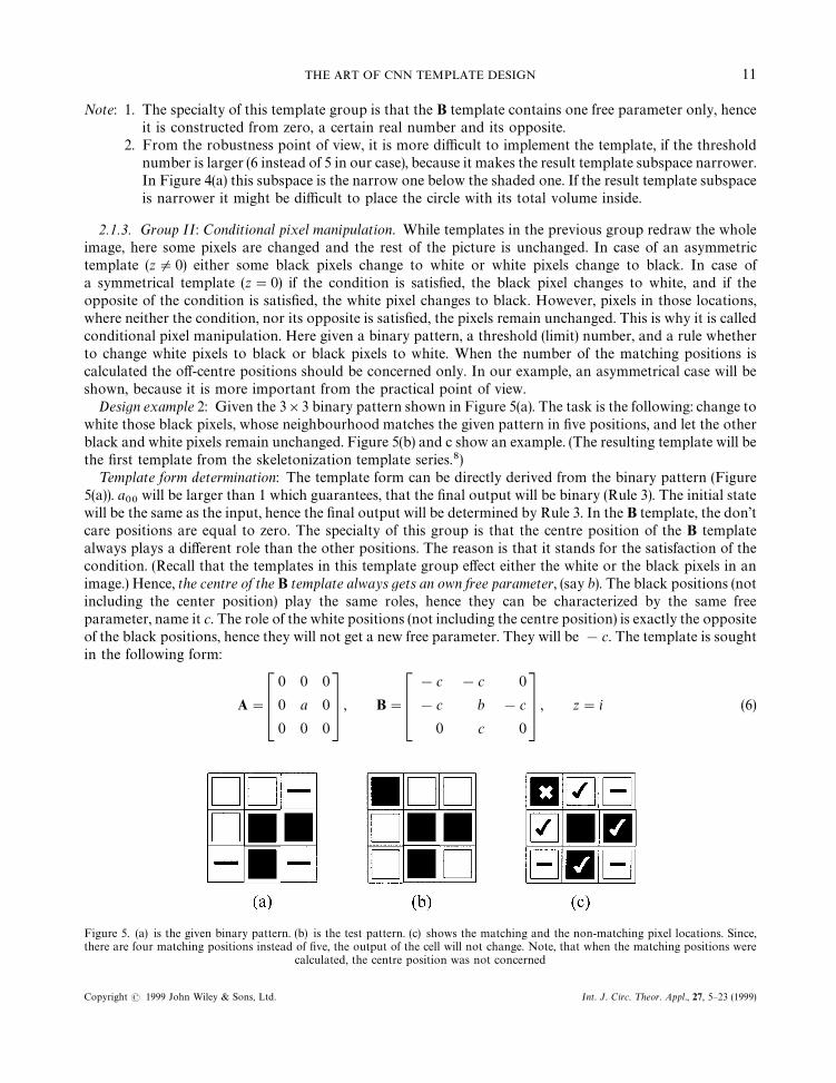
2.1.3. Group II: Conditional pixel manipulation. While templates in the previous group redraw the wholeimage, here some pixels are changed and the rest of the picture is unchanged. In case of an asymmetrictemplate (zO0) either some black pixels change to white or white pixels change to black. In case ofa symmetrical template (z"0) if the condition is satisfied, the black pixel changes to white, and if theopposite of the condition is satisfied, the white pixel changes to black. However, pixels in those locations,where neither the condition, nor its opposite is satisfied, the pixels remain unchanged. This is why it is calledconditional pixel manipulation. Here given a binary pattern, a threshold (limit) number, and a rule whetherto change white pixels to black or black pixels to white. When the number of the matching positions iscalculated the off-centre positions should be concerned only. In our example, an asymmetrical case will beshown, because it is more important from the practical point of view.
Design example 2: Given the 3]3 binary pattern shown in Figure 5(a). The task is the following: change towhite those black pixels, whose neighbourhood matches the given pattern in five positions, and let the otherblack and white pixels remain unchanged. Figure 5(b) and c show an example. (The resulting template will bethe first template from the skeletonization template series.8)
¹emplate form determination: The template form can be directly derived from the binary pattern (Figure5(a)). a
00will be larger than 1 which guarantees, that the final output will be binary (Rule 3). The initial state
will be the same as the input, hence the final output will be determined by Rule 3. In the B template, the don’tcare positions are equal to zero. The specialty of this group is that the centre position of the B templatealways plays a different role than the other positions. The reason is that it stands for the satisfaction of thecondition. (Recall that the templates in this template group effect either the white or the black pixels in animage.) Hence, the centre of the B template always gets an own free parameter, (say b). The black positions (notincluding the center position) play the same roles, hence they can be characterized by the same freeparameter, name it c. The role of the white positions (not including the centre position) is exactly the oppositeof the black positions, hence they will not get a new free parameter. They will be !c. The template is soughtin the following form:
A"C0 0 0
0 a 0
0 0 0D , B"C!c !c 0
!c b !c
0 c 0D , z"i (6)
Figure 5. (a) is the given binary pattern. (b) is the test pattern. (c) shows the matching and the non-matching pixel locations. Since,there are four matching positions instead of five, the output of the cell will not change. Note, that when the matching positions were
calculated, the centre position was not concerned
THE ART OF CNN TEMPLATE DESIGN 11
Copyright ( 1999 John Wiley & Sons, Ltd. Int. J. Circ. ¹heor. Appl., 27, 5—23 (1999)
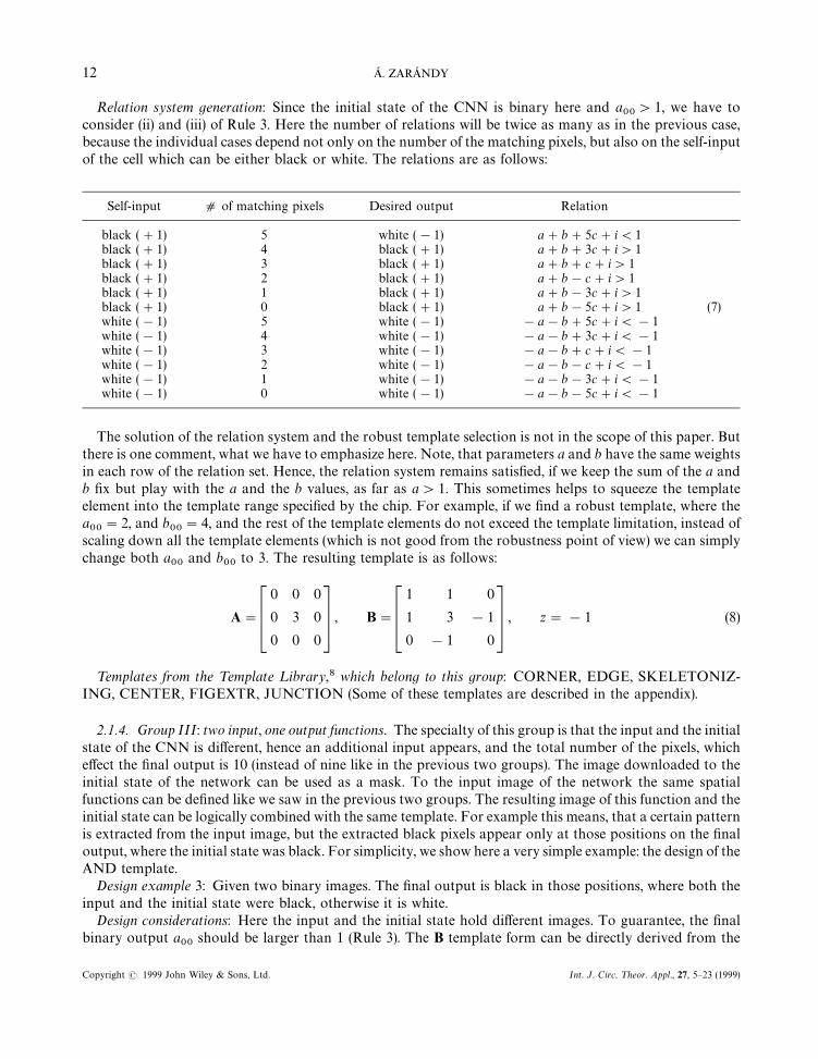
Relation system generation: Since the initial state of the CNN is binary here and a00'1, we have to
consider (ii) and (iii) of Rule 3. Here the number of relations will be twice as many as in the previous case,because the individual cases depend not only on the number of the matching pixels, but also on the self-inputof the cell which can be either black or white. The relations are as follows:
Self-input d of matching pixels Desired output Relation
black (#1) 5 white (!1) a#b#5c#i(1black (#1) 4 black (#1) a#b#3c#i'1black (#1) 3 black (#1) a#b#c#i'1black (#1) 2 black (#1) a#b!c#i'1black (#1) 1 black (#1) a#b!3c#i'1black (#1) 0 black (#1) a#b!5c#i'1 (7)white (!1) 5 white (!1) !a!b#5c#i(!1white (!1) 4 white (!1) !a!b#3c#i(!1white (!1) 3 white (!1) !a!b#c#i(!1white (!1) 2 white (!1) !a!b!c#i(!1white (!1) 1 white (!1) !a!b!3c#i(!1white (!1) 0 white (!1) !a!b!5c#i(!1
The solution of the relation system and the robust template selection is not in the scope of this paper. Butthere is one comment, what we have to emphasize here. Note, that parameters a and b have the same weightsin each row of the relation set. Hence, the relation system remains satisfied, if we keep the sum of the a andb fix but play with the a and the b values, as far as a'1. This sometimes helps to squeeze the templateelement into the template range specified by the chip. For example, if we find a robust template, where thea00"2, and b
00"4, and the rest of the template elements do not exceed the template limitation, instead of
scaling down all the template elements (which is not good from the robustness point of view) we can simplychange both a
00and b
00to 3. The resulting template is as follows:
A"C0 0 0
0 3 0
0 0 0D , B"C1 1 0
1 3 !1
0 !1 0D , z"!1 (8)
¹emplates from the ¹emplate ¸ibrary,8 which belong to this group: CORNER, EDGE, SKELETONIZ-ING, CENTER, FIGEXTR, JUNCTION (Some of these templates are described in the appendix).
2.1.4. Group III: two input, one output functions. The specialty of this group is that the input and the initialstate of the CNN is different, hence an additional input appears, and the total number of the pixels, whicheffect the final output is 10 (instead of nine like in the previous two groups). The image downloaded to theinitial state of the network can be used as a mask. To the input image of the network the same spatialfunctions can be defined like we saw in the previous two groups. The resulting image of this function and theinitial state can be logically combined with the same template. For example this means, that a certain patternis extracted from the input image, but the extracted black pixels appear only at those positions on the finaloutput, where the initial state was black. For simplicity, we show here a very simple example: the design of theAND template.
Design example 3: Given two binary images. The final output is black in those positions, where both theinput and the initial state were black, otherwise it is white.
Design considerations: Here the input and the initial state hold different images. To guarantee, the finalbinary output a
00should be larger than 1 (Rule 3). The B template form can be directly derived from the
12 A. ZARANDY
Copyright ( 1999 John Wiley & Sons, Ltd. Int. J. Circ. ¹heor. Appl., 27, 5—23 (1999)
binary pattern, as it was shown in the previous two cases. The final output will be determined by Rule 3. Thegeneration of the relation system is similar to the previous cases.
¹emplates from the ¹emplate ¸ibrary [8], which belong to this group: LOGAND, LOGDIF, LOGOR,LOGORN.
2.1.5. Comments: Generally, all of these functions can be described as a 10 input one output logicfunction. Only a small fraction of these 21024 logic functions can be implemented with a single CNNtemplate, the rest of them can be implemented with a few templates. A theoretical analysis of this problem isdescribed in References 11, and 13.
3. COUPLED CNN TEMPLATES
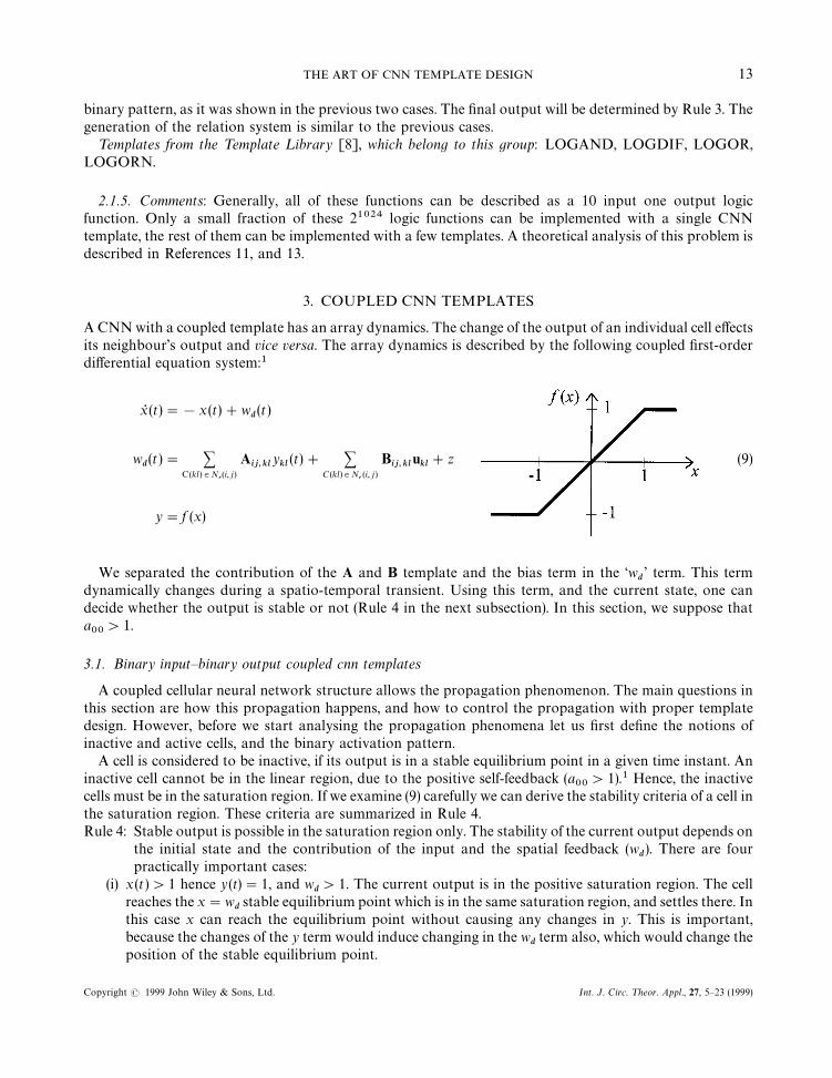
A CNN with a coupled template has an array dynamics. The change of the output of an individual cell effectsits neighbour’s output and vice versa. The array dynamics is described by the following coupled first-orderdifferential equation system:1
xR (t)"!x (t)#wd(t)
wd(t )" +
C(kl)3Nr(i, j)
Aij,kl
ykl
(t)# +C (kl)3N
r(i, j)
Bij,kl
ukl#z (9)
y"f (x)
We separated the contribution of the A and B template and the bias term in the ‘wd’ term. This term
dynamically changes during a spatio-temporal transient. Using this term, and the current state, one candecide whether the output is stable or not (Rule 4 in the next subsection). In this section, we suppose thata00'1.
3.1. Binary input—binary output coupled cnn templates
A coupled cellular neural network structure allows the propagation phenomenon. The main questions inthis section are how this propagation happens, and how to control the propagation with proper templatedesign. However, before we start analysing the propagation phenomena let us first define the notions ofinactive and active cells, and the binary activation pattern.
A cell is considered to be inactive, if its output is in a stable equilibrium point in a given time instant. Aninactive cell cannot be in the linear region, due to the positive self-feedback (a
00'1).1 Hence, the inactive
cells must be in the saturation region. If we examine (9) carefully we can derive the stability criteria of a cell inthe saturation region. These criteria are summarized in Rule 4.Rule 4: Stable output is possible in the saturation region only. The stability of the current output depends on
the initial state and the contribution of the input and the spatial feedback (wd). There are four
practically important cases:(i) x (t )'1 hence y(t)"1, and w
d'1. The current output is in the positive saturation region. The cell
reaches the x"wdstable equilibrium point which is in the same saturation region, and settles there. In
this case x can reach the equilibrium point without causing any changes in y. This is important,because the changes of the y term would induce changing in the w
dterm also, which would change the
position of the stable equilibrium point.
THE ART OF CNN TEMPLATE DESIGN 13
Copyright ( 1999 John Wiley & Sons, Ltd. Int. J. Circ. ¹heor. Appl., 27, 5—23 (1999)
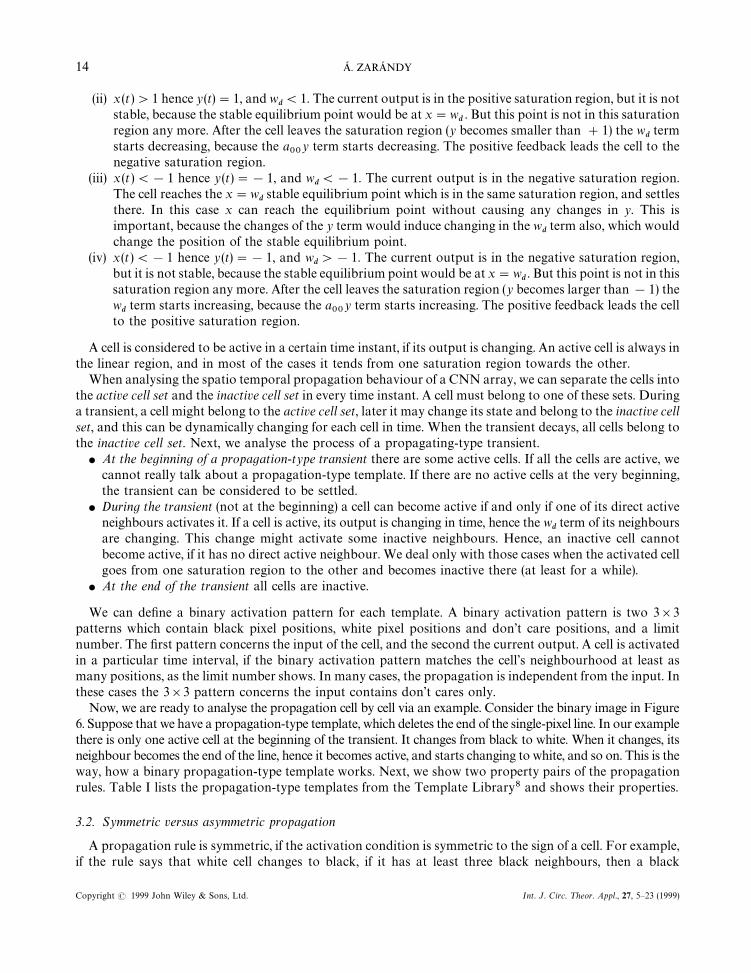
(ii) x (t )'1 hence y(t)"1, and wd(1. The current output is in the positive saturation region, but it is not
stable, because the stable equilibrium point would be at x"wd. But this point is not in this saturation
region any more. After the cell leaves the saturation region (y becomes smaller than #1) the wdterm
starts decreasing, because the a00
y term starts decreasing. The positive feedback leads the cell to thenegative saturation region.
(iii) x (t )(!1 hence y(t)"!1, and wd(!1. The current output is in the negative saturation region.
The cell reaches the x"wdstable equilibrium point which is in the same saturation region, and settles
there. In this case x can reach the equilibrium point without causing any changes in y. This isimportant, because the changes of the y term would induce changing in the w
dterm also, which would
change the position of the stable equilibrium point.(iv) x(t)(!1 hence y (t)"!1, and w
d'!1. The current output is in the negative saturation region,
but it is not stable, because the stable equilibrium point would be at x"wd. But this point is not in this
saturation region any more. After the cell leaves the saturation region (y becomes larger than!1) thewdterm starts increasing, because the a
00y term starts increasing. The positive feedback leads the cell
to the positive saturation region.
A cell is considered to be active in a certain time instant, if its output is changing. An active cell is always inthe linear region, and in most of the cases it tends from one saturation region towards the other.
When analysing the spatio temporal propagation behaviour of a CNN array, we can separate the cells intothe active cell set and the inactive cell set in every time instant. A cell must belong to one of these sets. Duringa transient, a cell might belong to the active cell set, later it may change its state and belong to the inactive cellset, and this can be dynamically changing for each cell in time. When the transient decays, all cells belong tothe inactive cell set. Next, we analyse the process of a propagating-type transient.
f At the beginning of a propagation-type transient there are some active cells. If all the cells are active, wecannot really talk about a propagation-type template. If there are no active cells at the very beginning,the transient can be considered to be settled.
f During the transient (not at the beginning) a cell can become active if and only if one of its direct activeneighbours activates it. If a cell is active, its output is changing in time, hence the w
dterm of its neighbours
are changing. This change might activate some inactive neighbours. Hence, an inactive cell cannotbecome active, if it has no direct active neighbour. We deal only with those cases when the activated cellgoes from one saturation region to the other and becomes inactive there (at least for a while).
f At the end of the transient all cells are inactive.
We can define a binary activation pattern for each template. A binary activation pattern is two 3]3patterns which contain black pixel positions, white pixel positions and don’t care positions, and a limitnumber. The first pattern concerns the input of the cell, and the second the current output. A cell is activatedin a particular time interval, if the binary activation pattern matches the cell’s neighbourhood at least asmany positions, as the limit number shows. In many cases, the propagation is independent from the input. Inthese cases the 3]3 pattern concerns the input contains don’t cares only.
Now, we are ready to analyse the propagation cell by cell via an example. Consider the binary image in Figure6. Suppose that we have a propagation-type template, which deletes the end of the single-pixel line. In our examplethere is only one active cell at the beginning of the transient. It changes from black to white. When it changes, itsneighbour becomes the end of the line, hence it becomes active, and starts changing to white, and so on. This is theway, how a binary propagation-type template works. Next, we show two property pairs of the propagationrules. Table I lists the propagation-type templates from the Template Library8 and shows their properties.
3.2. Symmetric versus asymmetric propagation
A propagation rule is symmetric, if the activation condition is symmetric to the sign of a cell. For example,if the rule says that white cell changes to black, if it has at least three black neighbours, then a black
14 A. ZARANDY
Copyright ( 1999 John Wiley & Sons, Ltd. Int. J. Circ. ¹heor. Appl., 27, 5—23 (1999)
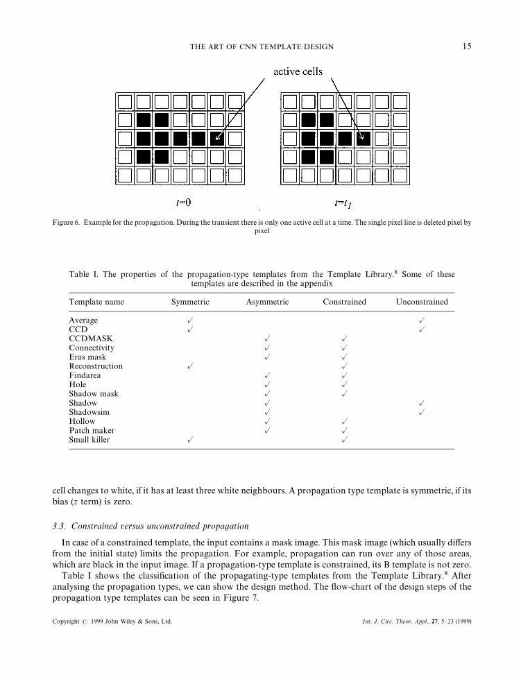
Figure 6. Example for the propagation. During the transient there is only one active cell at a time. The single pixel line is deleted pixel bypixel
Table I. The properties of the propagation-type templates from the Template Library.8 Some of thesetemplates are described in the appendix
Template name Symmetric Asymmetric Constrained Unconstrained
Average @ @CCD @ @CCDMASK @ @Connectivity @ @Eras mask @ @Reconstruction @ @Findarea @ @Hole @ @Shadow mask @ @Shadow @ @Shadowsim @ @Hollow @ @Patch maker @ @Small killer @ @
cell changes to white, if it has at least three white neighbours. A propagation type template is symmetric, if itsbias (z term) is zero.
3.3. Constrained versus unconstrained propagation
In case of a constrained template, the input contains a mask image. This mask image (which usually differsfrom the initial state) limits the propagation. For example, propagation can run over any of those areas,which are black in the input image. If a propagation-type template is constrained, its B template is not zero.
Table I shows the classification of the propagating-type templates from the Template Library.8 Afteranalysing the propagation types, we can show the design method. The flow-chart of the design steps of thepropagation type templates can be seen in Figure 7.
THE ART OF CNN TEMPLATE DESIGN 15
Copyright ( 1999 John Wiley & Sons, Ltd. Int. J. Circ. ¹heor. Appl., 27, 5—23 (1999)
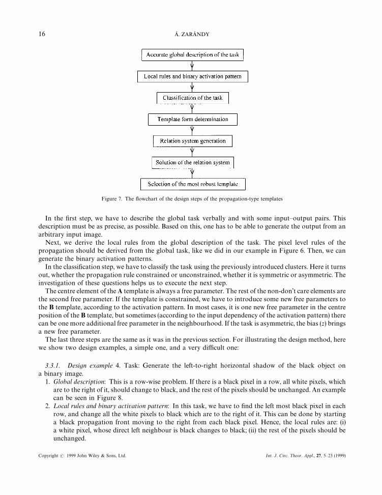
Figure 7. The flowchart of the design steps of the propagation-type templates
In the first step, we have to describe the global task verbally and with some input—output pairs. Thisdescription must be as precise, as possible. Based on this, one has to be able to generate the output from anarbitrary input image.
Next, we derive the local rules from the global description of the task. The pixel level rules of thepropagation should be derived from the global task, like we did in our example in Figure 6. Then, we cangenerate the binary activation patterns.
In the classification step, we have to classify the task using the previously introduced clusters. Here it turnsout, whether the propagation rule constrained or unconstrained, whether it is symmetric or asymmetric. Theinvestigation of these questions helps us to execute the next step.
The centre element of the A template is always a free parameter. The rest of the non-don’t care elements arethe second free parameter. If the template is constrained, we have to introduce some new free parameters tothe B template, according to the activation pattern. In most cases, it is one new free parameter in the centreposition of the B template, but sometimes (according to the input dependency of the activation pattern) therecan be one more additional free parameter in the neighbourhood. If the task is asymmetric, the bias (z) bringsa new free parameter.
The last three steps are the same as it was in the previous section. For illustrating the design method, herewe show two design examples, a simple one, and a very difficult one:
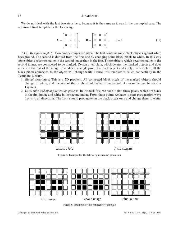
3.3.1. Design example 4. Task: Generate the left-to-right horizontal shadow of the black object ona binary image.
1. Global description: This is a row-wise problem. If there is a black pixel in a row, all white pixels, whichare to the right of it, should change to black, and the rest of the pixels should be unchanged. An examplecan be seen in Figure 8.
2. ¸ocal rules and binary activation pattern: In this task, we have to find the left most black pixel in eachrow, and change all the white pixels to black which are to the right of it. This can be done by startinga black propagation front moving to the right from each black pixel. Hence, the local rules are: (i)a white pixel, whose direct left neighbour is black changes to black; (ii) the rest of the pixels should beunchanged.
16 A. ZARANDY
Copyright ( 1999 John Wiley & Sons, Ltd. Int. J. Circ. ¹heor. Appl., 27, 5—23 (1999)
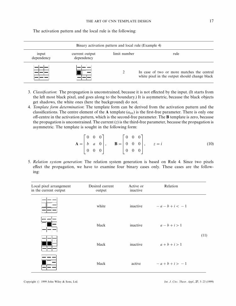
The activation pattern and the local rule is the following:
Binary activation pattern and local rule (Example 4)
input current output limit number ruledependency dependency
2 In case of two or more matches the centralwhite pixel in the output should change black
3. Classification: The propagation is unconstrained, because it is not effected by the input. (It starts fromthe left most black pixel, and goes along to the boundary.) It is asymmetric, because the black objectsget shadows, the white ones (here the background) do not.
4. ¹emplate form determination: The template form can be derived from the activation pattern and theclassifications. The centre element of the A template (a
00) is the first-free parameter. There is only one
off-centre in the activation pattern, which is the second-free parameter. The B template is zero, becausethe propagation is unconstrained. The current (z) is the third-free parameter, because the propagation isasymmetric. The template is sought in the following form:
A"C0 0 0
b a 0
0 0 0D , B"C0 0 0
0 0 0
0 0 0D , z"i (10)
5. Relation system generation: The relation system generation is based on Rule 4. Since two pixelseffect the propagation, we have to examine four binary cases only. These cases are the follow-ing:
Local pixel arrangement Desired current Active or Relationin the current output output inactive
white inactive !a!b#i(!1
black inactive a!b#i'1
(11)
black inactive a#b#i'1
black active !a#b#i'!1
THE ART OF CNN TEMPLATE DESIGN 17
Copyright ( 1999 John Wiley & Sons, Ltd. Int. J. Circ. ¹heor. Appl., 27, 5—23 (1999)
We do not deal with the last two steps here, because it is the same as it was in the uncoupled case. Theoptimized final template is the following:
A"C0 0 0
1 2 0
0 0 0D , B"C0 0 0
0 0 0
0 0 0D , z"1 (12)
3.3.2. Design example 5. Two binary images are given. The first contains some black objects against whitebackground. The second is derived from the first one by changing some black pixels to white. In this waysome objects become smaller in the second image than in the first. Those objects, which became smaller in thesecond image, are considered to be marked. Design a template, which deletes the marked objects and doesnot effect the rest of the image. If we delete a single pixel of a black object and apply this template, all theblack pixels connected to the object will change white. Hence, this template is called connectivity in theTemplate Library.
1. Global description: This is a 2D problem. All connected black pixels of the marked objects shouldchange to white, and the rest of the pixels should remain unchanged. An example can be seen inFigure 9.
2. ¸ocal rules and binary activation pattern: In this task first, we have to find those pixels, which are blackin the first image and white in the second image. From these points we have to start propagation wavefronts to all directions. The front should propagate on the black pixels only and change them to white.
Figure 8. Example for the left-to-right shadow generation
Figure 9. Example for the connectivity template
18 A. ZARANDY
Copyright ( 1999 John Wiley & Sons, Ltd. Int. J. Circ. ¹heor. Appl., 27, 5—23 (1999)
Since the wave front moves on the second image, it will be the initial state and the first image will bethe input. Hence, the local rules are the following: (i) change those black pixels white which haveat least one neighbouring cell with white output and black input, and (ii) do not change the rest of thepixels. At the same time, it is clear from the task specification that if a pixel is black in the second image(current output), it must be black in the first image (input) also. From this it follows that here thedifference of the output and the input counts instead of simply the output value of the neighbouringcells.
We introduce a new sign in the activation pattern. The delta sign (*) means that the particularneighbour activates the cell if and only if its output and its input is different. Note that the definition ofthe task excludes those situations when the output is black and the input is white. So, here the delta sign(the match) mean that the current output is white and the input is black in a particular position. A blackcell becomes active if it has at least one matching neighbour. For simplicity, we used four neighbour-hoods. The activation pattern is the following:
Binary activation pattern and local rule (Example 5)
input current output limit number ruledependency dependency
1
If the central input and central current output isblack, and there are one or more matches, thecentral black pixel in the output should changewhite.
3. Classification: The propagation is constrained, because it can go over the black areas only. It isasymmetric, because it deals with the black objects, the originally white pixels are unchanged.
4. ¹emplate form determination: As usual the template form can be derived from the activation pattern andthe classifications. The centre element of the A template (a
00) is the first-free parameter. The delta
operators in the neighbourhood affect both the A template and the B template. A neighbour which hasthe same input and output (both can be black or white) does not affect the cell. But if it has a black inputand a white output it activates the cell. Hence, the second-free parameter appears in the neighbourhoodin both the A and the B template, but with opposite sign. The centre element of the B template is thethird-free parameter. Since the propagation is asymmetric, the bias (z) is the fourth-free parameter. Thetemplate is sought in the following form:
A"C0 b 0
b a b
0 b 0D , B"C0 !b 0
!b c !b
0 !b 0 D , z"i (13)
5. Relation system generation: The relation system generation is based on Rule 4. Since there are onlythree valid binary input—output combinations here, and five matching possibilities, there are 15 differentcases. All cases yield a relation. The relation set is the following:
THE ART OF CNN TEMPLATE DESIGN 19
Copyright ( 1999 John Wiley & Sons, Ltd. Int. J. Circ. ¹heor. Appl., 27, 5—23 (1999)
output input d of matching active or desired output relationpixels inactive
black (#1) black (#1) 0 inactive black (#1) a#c#i'1black (#1) black (#1) 1 active white (!1) a!2b#c#i(1black (#1) black (#1) 2 active white (!1) a!4b#c#i(1black (#1) black (#1) 3 active white (!1) a!6b#c#i(1black (#1) black (#1) 4 active white (!1) a!8b#c#i(1white (!1) black (#1) 0 inactive white (!1) !a#c#i(!1white (!1) black (#1) 1 inactive white (!1) !a!2b#c#i(!1white (!1) black (#1) 2 inactive white (!1) !a!4b#c#i(!1 (14)white (!1) black (#1) 3 inactive white (!1) !a!6b#c#i(!1white (!1) black (#1) 4 inactive white (!1) !a!8b#c#i(!1white (!1) white (!1) 0 inactive white (!1) !a!c#i(!1white (!1) white (!1) 1 inactive white (!1) !a!2b!c!i(!1white (!1) white (!1) 2 inactive white (!1) !a!4b!c#i(!1white (!1) white (!1) 3 inactive white (!1) !a!6b!c#i(!1white (!1) white (!1) 4 inactive white (!1) !a!8b!c#i(!1
We do not deal with the last two steps here, because it is the same as it was in the uncoupled case. Theoptimized final template is the following:
A"C0 1 0
1 3 1
0 1 0D , B"C0 !1 0
!1 3 !1
0 !1 0 D , z"!4 (15)
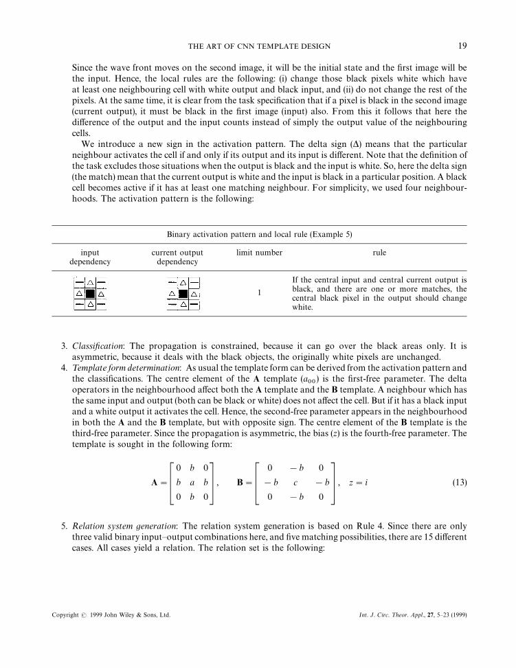
A more complex example can be seen for the propagation of this template. The interesting feature of thisexample is that it contradicts Minsky’s statement. Minsky said, that the global connectivity problem cannotbe solved with the locally interconnected network.
Figure 10. A more complex example for the propagation of the connectivity template
20 A. ZARANDY
Copyright ( 1999 John Wiley & Sons, Ltd. Int. J. Circ. ¹heor. Appl., 27, 5—23 (1999)
4. CONCLUSIONS
A classification and a systematic design method of the uncoupled and coupled binary input binary out-put CNN templates were introduced. Design examples for all template classes with robustness consid-erations were provided. The binary input binary output templates from the Template Library8were classified. The design method provides the whole theoretically operational template set. Fromthese infinitely many templates, one can find the most robust one, or the fastest one or any optimum bet-ween them.
APPENDIX: DESCRIPTION OF SOME TEMPLATES
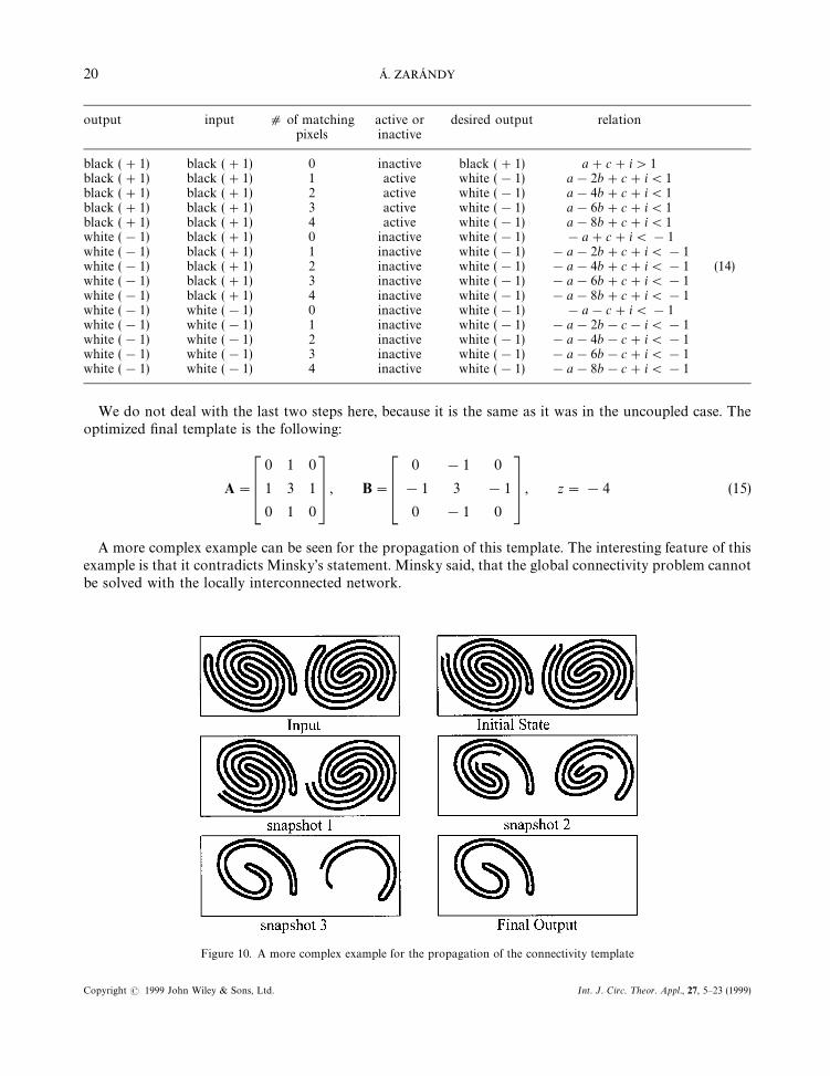
LSE: Local southern element detector
A"
0 0 0
0 1 0
0 0 0
, B"
0 0 0
0 1 0
!1 !1 !1
, z" !3
Function: Extracts the local southern pixels of the objects. Note: local southern elements are black pixelshaving neither southwestern, nor southern, nor southeastern black neighbours.
Example: Image size: 17]17.
JUNCTION: Extracts the junctions in line-draws
A"
0 0 0
0 1 0
0 0 0
, B"
1 1 1
1 6 1
1 1 1
, z" !3
Function: Extracts the junctions of single line objects. Note: A black pixel is considered to be a junction if ithas at least 3 black neighbours.
THE ART OF CNN TEMPLATE DESIGN 21
Copyright ( 1999 John Wiley & Sons, Ltd. Int. J. Circ. ¹heor. Appl., 27, 5—23 (1999)
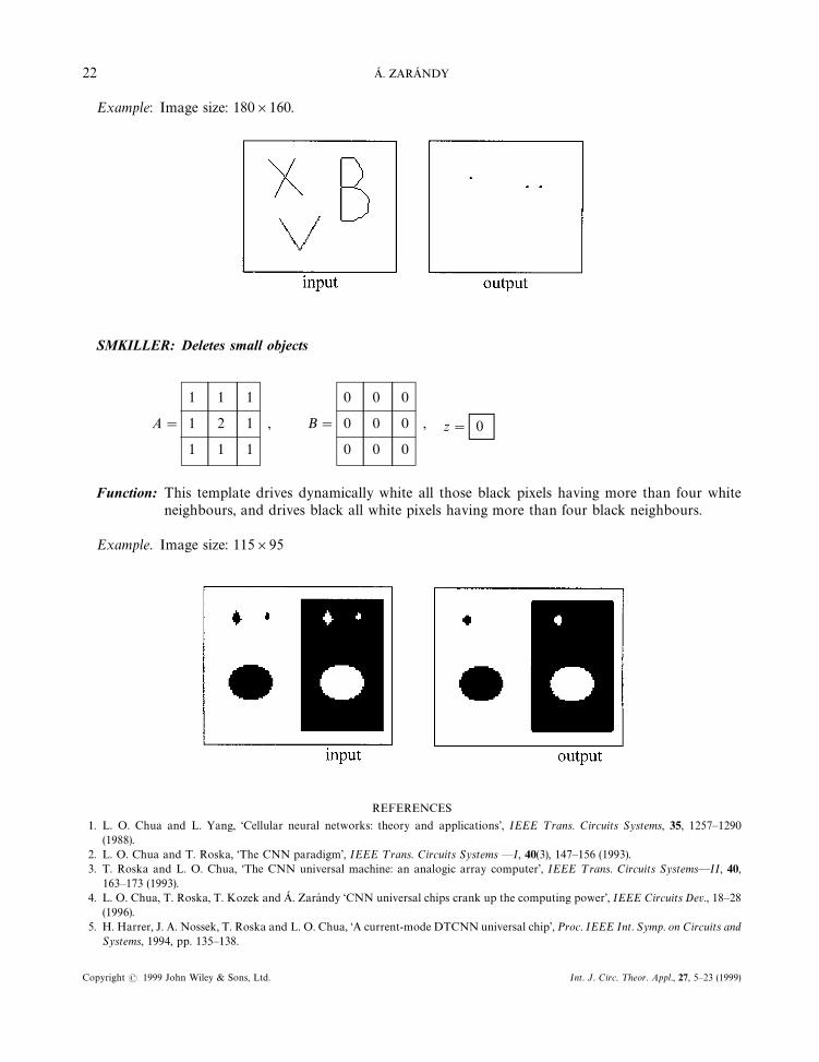
Example: Image size: 180]160.
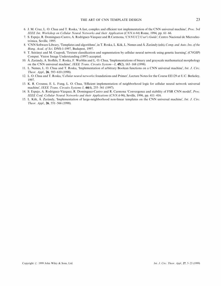
SMKILLER: Deletes small objects
A"
1 1 1
1 2 1
1 1 1
, B"
0 0 0
0 0 0
0 0 0
, z" 0
Function: This template drives dynamically white all those black pixels having more than four whiteneighbours, and drives black all white pixels having more than four black neighbours.
Example. Image size: 115]95
REFERENCES
1. L. O. Chua and L. Yang, ‘Cellular neural networks: theory and applications’, IEEE ¹rans. Circuits Systems, 35, 1257—1290(1988).
2. L. O. Chua and T. Roska, ‘The CNN paradigm’, IEEE ¹rans. Circuits Systems —I, 40(3), 147—156 (1993).3. T. Roska and L. O. Chua, ‘The CNN universal machine: an analogic array computer’, IEEE ¹rans. Circuits Systems—II, 40,
163—173 (1993).4. L. O. Chua, T. Roska, T. Kozek and A. Zarandy ‘CNN universal chips crank up the computing power’, IEEE Circuits Dev., 18—28
(1996).5. H. Harrer, J. A. Nossek, T. Roska and L. O. Chua, ‘A current-mode DTCNN universal chip’, Proc. IEEE Int. Symp. on Circuits and
Systems, 1994, pp. 135—138.
22 A. ZARANDY
Copyright ( 1999 John Wiley & Sons, Ltd. Int. J. Circ. ¹heor. Appl., 27, 5—23 (1999)
6. J. M. Cruz, L. O. Chua and T. Roska, ‘A fast, complex and efficient test implementation of the CNN universal machine’, Proc. 3rdIEEE Int. ¼orkshop on Cellular Neural Networks and their Application (CNNA-94) Rome, 1994, pp. 61—66.
7. S. Espejo, R. Dominguez-Castro, A. Rodriguez-Vazquez and R.Carmona, ‘CNNºC2 ºser’s Guide’, Centro Nacional de Microelec-tronica, Seville, 1995.
8. ‘CNN Software Library, ‘Templates and algorithms’, in T. Roska, L. Kek, L. Nemes and A. Zarandy (eds), Comp. and Auto. Ins. of theHung. Acad. of Sci. DNS-1-1997, Budapest, 1997.
9. T. Sziranyi and M. Csapodi, ‘Texture classification and segmentation by cellular neural network using genetic learning’, (CVGIP)Comput. Vision Image Understanding (1997) accepted.
10. A. Zarandy, A. Stoffels, T. Roska, F. Werblin and L. O. Chua, ‘Implementations of binary and grayscale mathematical morphologyon the CNN universal machine’, IEEE ¹rans. Circuits System—I, 45(2), 163—168 (1998).
11. L. Nemes, L. O. Chua and T. Roska, ‘Implementation of arbitrary Boolean functions on a CNN universal machine’, Int. J. Circ.¹heor. Appl., 26, 593—610 (1998).
12. L. O. Chua and T. Roska, ‘Cellular neural networks: foundations and Primer’, Lecture Notes for the Course EE129 at U.C. Berkeley,1997.
13. K. R. Crounse, E. L. Fung, L. O. Chua, ‘Efficient implementation of neighborhood logic for cellular neural network universalmachine’, IEEE ¹rans. Circuits Systems I, 44(4), 255—361 (1997).
14. S. Espejo, A. Rodriguez-Vazquez, R. Dominguez-Castro and R. Carmona ‘Convergence and stability of FSR CNN model’, Proc.IEEE Conf. Cellular Neural Networks and their Applications (CNNA-96), Seville, 1996, pp. 411—416.
15. L. Kek, A. Zarandy, ‘Implementation of large-neighborhood non-linear templates on the CNN universal machine’, Int. J. Circ.¹heor. Appl., 26, 551—566 (1998).
THE ART OF CNN TEMPLATE DESIGN 23
Copyright ( 1999 John Wiley & Sons, Ltd. Int. J. Circ. ¹heor. Appl., 27, 5—23 (1999)