Embed Size (px)
Citation preview
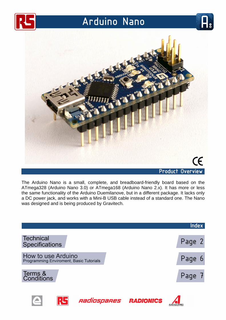
The Arduino Nano is a small, complete, and breadboard-friendly board based on the ATmega328 (Arduino Nano 3.0) or ATmega168 (Arduino Nano 2.x). It has more or less the same functionality of the Arduino Duemilanove, but in a different package. It lacks only a DC power jack, and works with a Mini-B USB cable instead of a standard one. The Nano was designed and is being produced by Gravitech.
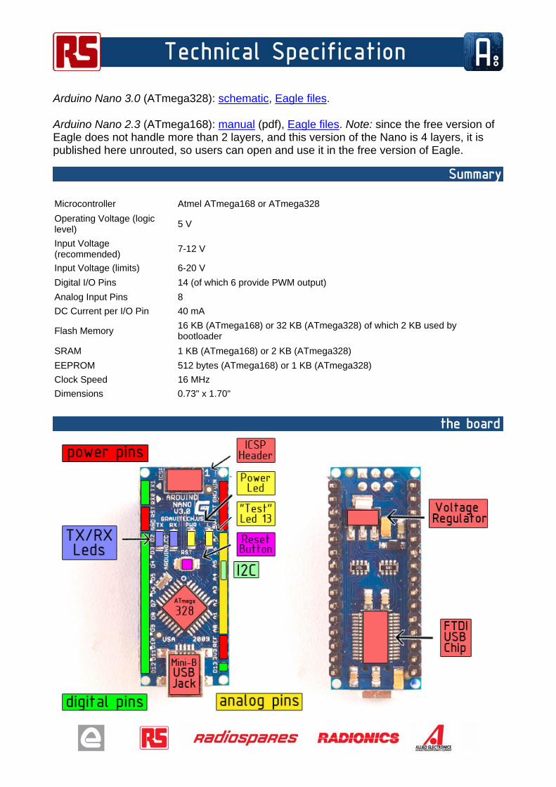
Arduino Nano 3.0 (ATmega328): schematic, Eagle files.
Arduino Nano 2.3 (ATmega168): manual (pdf), Eagle files. Note: since the free version of Eagle does not handle more than 2 layers, and this version of the Nano is 4 layers, it is published here unrouted, so users can open and use it in the free version of Eagle.
Microcontroller Atmel ATmega168 or ATmega328
Operating Voltage (logic level)
5 V
Input Voltage (recommended)
7-12 V
Input Voltage (limits) 6-20 V
Digital I/O Pins 14 (of which 6 provide PWM output)
Analog Input Pins 8
DC Current per I/O Pin 40 mA
Flash Memory 16 KB (ATmega168) or 32 KB (ATmega328) of which 2 KB used by bootloader
SRAM 1 KB (ATmega168) or 2 KB (ATmega328)
EEPROM 512 bytes (ATmega168) or 1 KB (ATmega328)
Clock Speed 16 MHz
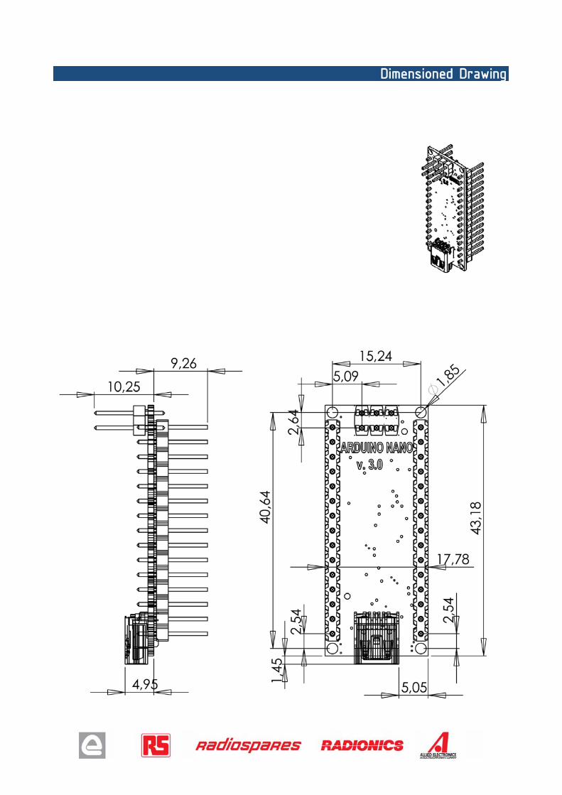
Dimensions 0.73" x 1.70"
The Arduino Nano can be powered via the Mini-B USB connection, 6-20V unregulated external power supply (pin 30), or 5V regulated external power supply (pin 27). The power source is automatically selected to the highest voltage source.
The FTDI FT232RL chip on the Nano is only powered if the board is being powered over USB. As a result, when running on external (non-USB) power, the 3.3V output (which is supplied by the FTDI chip) is not available and the RX and TX LEDs will flicker if digital pins 0 or 1 are high.
The ATmega168 has 16 KB of flash memory for storing code (of which 2 KB is used for the bootloader); the ATmega328 has 32 KB, (also with 2 KB used for the bootloader). The ATmega168 has 1 KB of SRAM and 512 bytes of EEPROM (which can be read and written with the EEPROM library); the ATmega328 has 2 KB of SRAM and 1 KB of EEPROM.
Each of the 14 digital pins on the Nano can be used as an input or output, using pinMode(), digitalWrite(), and digitalRead() functions. They operate at 5 volts. Each pin can provide or receive a maximum of 40 mA and has an internal pull-up resistor (disconnected by default) of 20-50 kOhms. In addition, some pins have specialized functions:
Serial: 0 (RX) and 1 (TX). Used to receive (RX) and transmit (TX) TTL serial data. These pins are connected to the corresponding pins of the FTDI USB-to-TTL Serial chip.
External Interrupts: 2 and 3. These pins can be configured to trigger an interrupt on a low value, a rising or falling edge, or a change in value. See the attachInterrupt() function for details.
PWM: 3, 5, 6, 9, 10, and 11. Provide 8-bit PWM output with the analogWrite() function. SPI: 10 (SS), 11 (MOSI), 12 (MISO), 13 (SCK). These pins support SPI communication, which,
although provided by the underlying hardware, is not currently included in the Arduino language. LED: 13. There is a built-in LED connected to digital pin 13. When the pin is HIGH value, the LED is
on, when the pin is LOW, it's off.
The Nano has 8 analog inputs, each of which provide 10 bits of resolution (i.e. 1024 different values). By default they measure from ground to 5 volts, though is it possible to change the upper end of their range using the analogReference() function. Additionally, some pins have specialized functionality:
I2C: 4 (SDA) and 5 (SCL). Support I2C (TWI) communication using the Wire library (documentation on the Wiring website).
There are a couple of other pins on the board:
AREF. Reference voltage for the analog inputs. Used with analogReference(). Reset. Bring this line LOW to reset the microcontroller. Typically used to add a reset button to
shields which block the one on the board.
See also the mapping between Arduino pins and ATmega168 ports.
The Arduino Nano has a number of facilities for communicating with a computer, another Arduino, or other microcontrollers. The ATmega168 and ATmega328 provide UART TTL (5V) serial communication, which is available on digital pins 0 (RX) and 1 (TX). An FTDI FT232RL on the board channels this serial communication over USB and the FTDI drivers (included with the Arduino software) provide a virtual com port to software on the computer. The Arduino software includes a serial monitor which allows simple textual data to be sent to and from the Arduino board. The RX and TX LEDs on the board will flash when data is being transmitted via the FTDI chip and USB connection to the computer (but not for serial communication on pins 0 and 1).
A SoftwareSerial library allows for serial communication on any of the Nano's digital pins.
The ATmega168 and ATmega328 also support I2C (TWI) and SPI communication. The Arduino software includes a Wire library to simplify use of the I2C bus; see the documentation for details. To use the SPI communication, please see the ATmega168 or ATmega328 datasheet.
The Arduino Nano can be programmed with the Arduino software (download). Select "Arduino Diecimila, Duemilanove, or Nano w/ ATmega168" or "Arduino Duemilanove or Nano w/ ATmega328" from the Tools > Board menu (according to the microcontroller on your board). For details, see the reference and tutorials.
The ATmega168 or ATmega328 on the Arduino Nano comes preburned with a bootloader that allows you to upload new code to it without the use of an external hardware programmer. It communicates using the original STK500 protocol (reference, C header files).
You can also bypass the bootloader and program the microcontroller through the ICSP (In-Circuit Serial Programming) header; see these instructions for details.
Rather then requiring a physical press of the reset button before an upload, the Arduino Nano is designed in a way that allows it to be reset by software running on a connected computer. One of the hardware flow control lines (DTR) of the FT232RL is connected to the reset line of the ATmega168 or ATmega328 via a 100 nanofarad capacitor. When this line is asserted (taken low), the reset line drops long enough to reset the chip. The Arduino software uses this capability to allow you to upload code by simply pressing the upload button in the Arduino environment. This means that the bootloader can have a shorter timeout, as the lowering of DTR can be well-coordinated with the start of the upload.
This setup has other implications. When the Nano is connected to either a computer running Mac OS X or Linux, it resets each time a connection is made to it from software (via USB). For the following half-second or so, the bootloader is running on the Nano. While it is programmed to ignore malformed data (i.e. anything besides an upload of new code), it will intercept the first few bytes of data sent to the board after a connection is opened. If a sketch running on the board receives one-time configuration or other data when it first starts, make sure that the software with which it communicates waits a second after opening the connection and before sending this data.
Arduino can sense the environment by receiving input from a variety of sensors and can affect its surroundings by controlling lights, motors, and other actuators. The microcontroller on the board is programmed using the Arduino programming language (based on Wiring) and the Arduino development environment (based on Processing). Arduino projects can be stand-alone or they can communicate with software on running on a computer (e.g. Flash, Processing, MaxMSP).
Arduino is a cross-platoform program. You’ll have to follow different instructions for your personal OS. Check on the Arduino site for the latest instructions. http://arduino.cc/en/Guide/HomePage
Once you have downloaded/unzipped the arduino IDE, you’ll need to install the FTDI Drivers to let your PC talk to the board. First Plug the Arduino to your PC via USB cable.
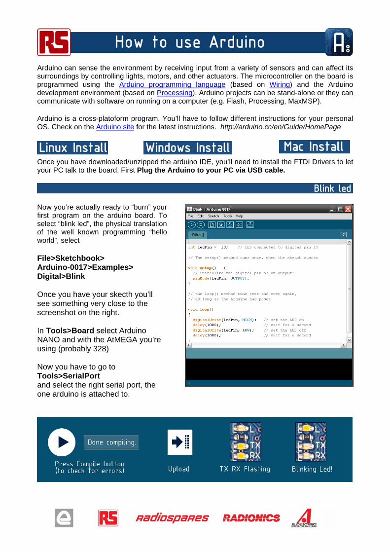
Now you’re actually ready to “burn” your first program on the arduino board. To select “blink led”, the physical translation of the well known programming “hello world”, select
File>Sketchbook> Arduino-0017>Examples> Digital>Blink Once you have your skecth you’ll see something very close to the screenshot on the right. In Tools>Board select Arduino NANO and with the AtMEGA you’re using (probably 328) Now you have to go to Tools>SerialPort and select the right serial port, the one arduino is attached to.
1. Warranties 1.1 The producer warrants that its products will conform to the Specifications. This warranty lasts for one (1) years from the date of the sale. The producer shall not be liable for any defects that are caused by neglect, misuse or mistreatment by the Customer, including improper installation or testing, or for any products that have been altered or modified in any way by a Customer. Moreover, The producer shall not be liable for any defects that result from Customer's design, specifications or instructions for such products. Testing and other quality control techniques are used to the extent the producer deems necessary. 1.2 If any products fail to conform to the warranty set forth above, the producer's sole liability shall be to replace such products. The producer's liability shall be limited to products that are determined by the producer not to conform to such warranty. If the producer elects to replace such products, the producer shall have a reasonable time to replacements. Replaced products shall be warranted for a new full warranty period. 1.3 EXCEPT AS SET FORTH ABOVE, PRODUCTS ARE PROVIDED "AS IS" AND "WITH ALL FAULTS." THE PRODUCER DISCLAIMS ALL OTHER WARRANTIES, EXPRESS OR IMPLIED, REGARDING PRODUCTS, INCLUDING BUT NOT LIMITED TO, ANY IMPLIED WARRANTIES OF MERCHANTABILITY OR FITNESS FOR A PARTICULAR PURPOSE 1.4 Customer agrees that prior to using any systems that include the producer products, Customer will test such systems and the functionality of the products as used in such systems. The producer may provide technical, applications or design advice, quality characterization, reliability data or other services. Customer acknowledges and agrees that providing these services shall not expand or otherwise alter the producer's warranties, as set forth above, and no additional obligations or liabilities shall arise from the producer providing such services. 1.5 The Arduino products are not authorized for use in safety-critical applications where a failure of the product would reasonably be expected to cause severe personal injury or death. Safety-Critical Applications include, without limitation, life support devices and systems, equipment or systems for the operation of nuclear facilities and weapons systems. Arduinoproducts are neither designed nor intended for use in military or aerospace applications or environments and for automotive applications or environment. Customer acknowledges and agrees that any such use of Arduino products which is solely at the Customer's risk, and that Customer is solely responsible for compliance with all legal and regulatory requirements in connection with such use. 1.6 Customer acknowledges and agrees that it is solely responsible for compliance with all legal, regulatory and safety-related requirements concerning its products and any use of Arduino products in Customer's applications, notwithstanding any applications-related information or support that may be provided by the producer. 2. Indemnification The Customer acknowledges and agrees to defend, indemnify and hold harmless the producer from and against any and all third-party losses, damages, liabilities and expenses it incurs to the extent directly caused by: (i) an actual breach by a Customer of the representation and warranties made under this terms and conditions or (ii) the gross negligence or willful misconduct by the Customer. 3. Consequential Damages Waiver In no event the producer shall be liable to the Customer or any third parties for any special, collateral, indirect, punitive, incidental, consequential or exemplary damages in connection with or arising out of the products provided hereunder, regardless of whether the producer has been advised of the possibility of such damages. This section will survive the termination of the warranty period. 4. Changes to specifications The producer may make changes to specifications and product descriptions at any time, without notice. The Customer must not rely on the absence or characteristics of any features or instructions marked "reserved" or "undefined." The producer reserves these for future definition and shall have no responsibility whatsoever for conflicts or incompatibilities arising from future changes to them. The product information on the Web Site or Materials is subject to change without notice. Do not finalize a design with this information.