Embed Size (px)
Citation preview
Ultrasonics 58 (2015) 96–103
Contents lists available at ScienceDirect
Ultrasonics
journal homepage: www.elsevier .com/ locate/ul t ras
The application of second-order approximation of Taylor seriesin thickness shear vibration analysis of quartz crystal microbalances
http://dx.doi.org/10.1016/j.ultras.2014.12.0070041-624X/� 2015 Elsevier B.V. All rights reserved.
⇑ Corresponding author. Fax: +86 29 82667091.E-mail address: [email protected] (F. Jin).
Peng Li a, Feng Jin b,⇑, Qing Sun a, Jianxun Ma a
a School of Human Settlements and Civil Engineering, Xi’an Jiaotong University, Xi’an 710049, Chinab State Key Laboratory for Strength and Vibration of Mechanical Structures, School of Aerospace, Xi’an Jiaotong University, Xi’an 710049, China
a r t i c l e i n f o a b s t r a c t
Article history:Received 1 June 2014Received in revised form 27 December 2014Accepted 29 December 2014Available online 6 January 2015
Keywords:Thickness shear vibrationSecond-order approximationFrequency shiftAdmittance analysisTransient effect
The inertia force caused by an additional mass layer is usually adopted to simulate the effective mechan-ical boundary condition in a quartz crystal microbalance (QCM), which may yield incorrect results whenthe upper layer becomes relative thicker. Thus, a detail analysis of the thickness shear vibration in a QCMfor detecting the characteristics of the upper isotropic layer is proceeded based on a second-orderapproximation of Taylor series. The result calculated by this method has a higher accuracy than that ofinertial-force approximation. According to these outcomes, the free and forced vibration has been illus-trated, as well as transient effects during the switching on/off processes or under a sudden fluctuation ofthe driving-voltage amplitude or frequency. It has been revealed by numerical simulation that the addi-tional mass layer has a great influence on the mechanical performance of QCM, including the resonancefrequency, amplitudes of displacement and admittance, response time of the transient processes, and soon. These findings can prove effective guidance for physical phenomenon explanations and experimentalmeasurement in mass sensor devices.
� 2015 Elsevier B.V. All rights reserved.
1. Introduction
Owning to its advantage of high sensitivity and distinguishabil-ity, the quartz crystal microbalance (QCM) has been regarded asvery convenient to detect physical property changes of thin layersat its surfaces, which has been widely used in many regions, suchas physics, biology, chemistry and medicine [1]. By changing thequality of the material under test into frequency signal, QCM canbe applied to measure the properties of affiliated layer [2]. Some-times, the resonance frequency can be reached gigahertz, with itsthickness typically in the range of some micro-meters. Hence, itis easy to measure mass densities of the attached layer down toa level of 1 lg/cm2 [3,4].
The frequency of oscillation, which is partially dependent on thethickness of the mass layer, is the basic performance index of theQCM. During the past decades, the effect of some mechanical char-acteristics on resonance frequency of QCM have been extensivelyinvestigated, including visco-elasticity [1], inhomogeneity of masslayer [5], imperfection of connected interface [6], electrical admit-tance [7], and so on. Among these explorations mentioned above,an inertia force caused by the thin layer is usually applied for the
description of mechanical boundary condition at the upper surfaceof the crystal plate [5,8,9], which replaces a detailed analysis ofmechanical and electrical coupling. Based on this simplification,Sauerbrey’s equation provides a simple computational formulaabout resonance frequency, which is proportional to the mass ofthe film attached [1]. However, it has been pointed that this kindof simplification may yield incorrect results especially when theupper layer becomes relative thicker [10]. Both the mass andstiffness effects must be considered during the analysis. Hence,the present paper will introduce a second-order approximationof Taylor series, which will be more accurate than the previousinertial-force approximation.
On the other hand, owning to the piezoelectricity of AT-cutcrystal plate, an alternative voltage applied on its two surfaces isusually used to excite a particular vibration mode. Anotherphenomenon, transient effect [11,12], is inevitable during the exci-tation process of QCM. For instance, the initial switching-on fromrest, followed by a sudden switching-off caused by the interruptionof incident current, fluctuations in the driving voltage or thefrequency, and thermal and mechanical shocks, and so forth. Theycan disturb resonator operation evidently. There have been a fewattempts to study the transient effect on the thickness-shear vibra-tion in quartz crystal resonators [13–15]. However, the theoreticalmodel mentioned above is simplified as a single infinite piezoelec-tric plate. To the best of our knowledge, little work has been
P. Li et al. / Ultrasonics 58 (2015) 96–103 97
performed so far to discuss the transient effect in the compositelayered structures, which contains at least two different materials.However, this is significant for the design of high-quality electronicdevices.
Synthesis above, a systematic investigation, including reso-nance frequency solving, forced vibration analysis, and some tran-sient responses, on the thickness shear vibration performance ofQCM is carried out in present contribution by using of a second-order approximation of Taylor series. The dispersion equation hasbeen obtained from linear elastic theory, which can be reducedto a few known elastic or quasi-static piezoelectric solutions. Basedon this equation, the effect of affiliated mass layer on some prop-erty indices of thickness shear mode, such as resonance frequency,displacement distribution, admittance amplitude, and transientresponse time, has been revealed numerically. Finally, some con-clusions are given.
2. Thickness-shear vibration analysis
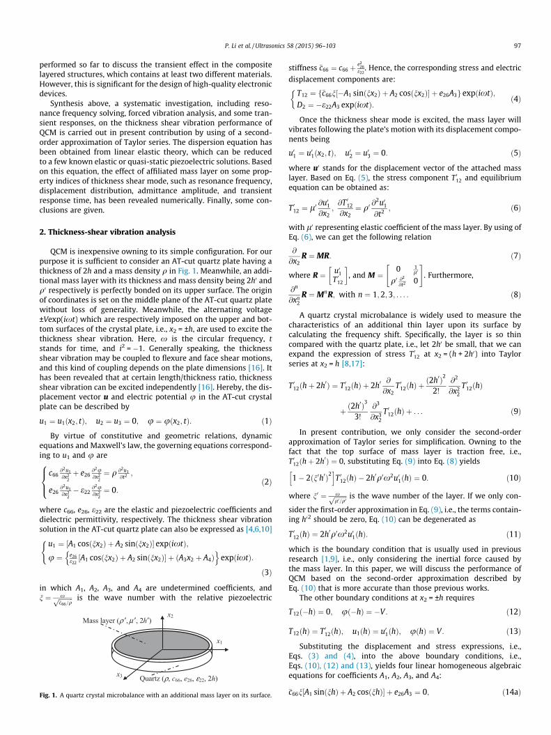
QCM is inexpensive owning to its simple configuration. For ourpurpose it is sufficient to consider an AT-cut quartz plate having athickness of 2h and a mass density q in Fig. 1. Meanwhile, an addi-tional mass layer with its thickness and mass density being 2h0 andq0 respectively is perfectly bonded on its upper surface. The originof coordinates is set on the middle plane of the AT-cut quartz platewithout loss of generality. Meanwhile, the alternating voltage±Vexp(ixt) which are respectively imposed on the upper and bot-tom surfaces of the crystal plate, i.e., x2 = ±h, are used to excite thethickness shear vibration. Here, x is the circular frequency, tstands for time, and i2 = �1. Generally speaking, the thicknessshear vibration may be coupled to flexure and face shear motions,and this kind of coupling depends on the plate dimensions [16]. Ithas been revealed that at certain length/thickness ratio, thicknessshear vibration can be excited independently [16]. Hereby, the dis-placement vector u and electric potential u in the AT-cut crystalplate can be described by
u1 ¼ u1ðx2; tÞ; u2 ¼ u3 ¼ 0; u ¼ uðx2; tÞ: ð1Þ
By virtue of constitutive and geometric relations, dynamicequations and Maxwell’s law, the governing equations correspond-ing to u1 and u are
c66@2u1@x2
2þ e26
@2u@x2
2¼ q @2u1
@t2 ;
e26@2u1@x2
2� e22
@2u@x2
2¼ 0:
8><>: ð2Þ
where c66, e26, e22 are the elastic and piezoelectric coefficients anddielectric permittivity, respectively. The thickness shear vibrationsolution in the AT-cut quartz plate can also be expressed as [4,6,10]
u1 ¼ A1 cosðnx2Þ þ A2 sinðnx2Þ½ � expðixtÞ;u ¼ e26
e22A1 cosðnx2Þ þ A2 sinðnx2Þ½ � þ ðA3x2 þ A4Þ
n oexpðixtÞ:
(
ð3Þ
in which A1, A2, A3, and A4 are undetermined coefficients, andn ¼ xffiffiffiffiffiffiffiffiffi
�c66=qp is the wave number with the relative piezoelectric
Mass layer (ρ ′, μ ′, 2h′) x2
x1
x3 Quartz (ρ, c66, e26, ε22, 2h)
Fig. 1. A quartz crystal microbalance with an additional mass layer on its surface.
stiffness �c66 ¼ c66 þe2
26e22
. Hence, the corresponding stress and electric
displacement components are:
T12 ¼ f�c66n½�A1 sinðnx2Þ þ A2 cosðnx2Þ� þ e26A3g expðixtÞ;D2 ¼ �e22A3 expðixtÞ:
�ð4Þ
Once the thickness shear mode is excited, the mass layer willvibrates following the plate’s motion with its displacement compo-nents being
u01 ¼ u01ðx2; tÞ; u02 ¼ u03 ¼ 0: ð5Þ
where u0 stands for the displacement vector of the attached masslayer. Based on Eq. (5), the stress component T 012 and equilibriumequation can be obtained as:
T 012 ¼ l0 @u01@x2
;@T 012
@x2¼ q0
@2u01@t2 ; ð6Þ
with l0 representing elastic coefficient of the mass layer. By using ofEq. (6), we can get the following relation
@
@x2R ¼MR: ð7Þ
where R ¼ u01T 012
� �, and M ¼
0 1l0
q0 @2
@t2 0
" #. Furthermore,
@n
@xn2
R ¼MnR; with n ¼ 1;2;3; . . . : ð8Þ
A quartz crystal microbalance is widely used to measure thecharacteristics of an additional thin layer upon its surface bycalculating the frequency shift. Specifically, the layer is so thincompared with the quartz plate, i.e., let 2h0 be small, that we canexpand the expression of stress T 012 at x2 = (h + 2h0) into Taylorseries at x2 = h [8,17]:
T 012ðhþ 2h0Þ ¼ T 012ðhÞ þ 2h0@
@x2T 012ðhÞ þ
ð2h0Þ2
2!
@2
@x22
T 012ðhÞ
þ ð2h0Þ3
3!
@3
@x32
T 012ðhÞ þ . . . ð9Þ
In present contribution, we only consider the second-orderapproximation of Taylor series for simplification. Owning to thefact that the top surface of mass layer is traction free, i.e.,T 012ðhþ 2h0Þ ¼ 0, substituting Eq. (9) into Eq. (8) yields
1� 2ðn0h0Þ2h i
T 012ðhÞ � 2h0q0x2u01ðhÞ ¼ 0: ð10Þ
where n0 ¼ xffiffiffiffiffiffiffiffil0=q0p is the wave number of the layer. If we only con-
sider the first-order approximation in Eq. (9), i.e., the terms contain-ing h02 should be zero, Eq. (10) can be degenerated as
T 012ðhÞ ¼ 2h0q0x2u01ðhÞ: ð11Þ
which is the boundary condition that is usually used in previousresearch [1,9], i.e., only considering the inertial force caused bythe mass layer. In this paper, we will discuss the performance ofQCM based on the second-order approximation described byEq. (10) that is more accurate than those previous works.
The other boundary conditions at x2 = ±h requires
T12ð�hÞ ¼ 0; uð�hÞ ¼ �V : ð12Þ
T12ðhÞ ¼ T 012ðhÞ; u1ðhÞ ¼ u01ðhÞ; uðhÞ ¼ V : ð13Þ
Substituting the displacement and stress expressions, i.e.,Eqs. (3) and (4), into the above boundary conditions, i.e.,Eqs. (10), (12) and (13), yields four linear homogeneous algebraicequations for coefficients A1, A2, A3, and A4:
�c66n½A1 sinðnhÞ þ A2 cosðnhÞ� þ e26A3 ¼ 0; ð14aÞ
0.86
0.88
0.90
0.92
0.94
0.96
0.98
1.00
ω / ω
s
h′/h
Second-order approximation First-order approximation Exact solution
0.00 0.02 0.04 0.06 0.08 0.10
Fig. 2. The frequency comparison calculated by three different equations.
98 P. Li et al. / Ultrasonics 58 (2015) 96–103
½1� 2ðn0h0Þ2�f�c66n½�A1 sinðnhÞ þ A2 cosðnhÞ� þ e26A3g� 2h0q0x2½A1 cosðnhÞ þ A2 sinðnhÞ� ¼ 0; ð14bÞ
e26
e22½A1 cosðnhÞ þ A2 sinðnhÞ� þ A3hþ A4 ¼ V ; ð14cÞ
e26
e22½A1 cosðnhÞ � A2 sinðnhÞ� � A3hþ A4 ¼ �V : ð14dÞ
These undermined coefficients A1, A2, A3, and A4 can be deducedas
A1¼�e26V�c66
2nhR0 sinðnhÞD
; A2¼� cotðnhÞþ 1nhR0
½1�2ðn0h0Þ2�� �
A1;
A3¼��c66
e26n A1 sinðnhÞþA2 cosðnhÞ½ �; A4¼�
e26
e22cosðnhÞA1:
ð15Þ
where
D ¼ 2 sinðnhÞ 1� 2ðn0h0Þ2h i
k226 sinðnhÞ � nh cosðnhÞ
h iþ nhR0 k2
26 sinð2nhÞ � 2nh cosð2nhÞh i
; ð16Þ
and R0 ¼ 2h0q02hq ¼
l0n0�c66n
2h0n0
2hn : D ¼ 0 yields the resonance frequency equa-tion of thickness shear vibration in the QCM in Fig. 1 when theupper and bottom surfaces of the crystal plate are electricallyshorted (i.e., without the initial voltage V = 0), which is related tothe free vibration of such composites.
2 sinðnhÞ 1� 2ðn0h0Þ2h i
k226 sinðnhÞ � nh cosðnhÞ
h iþ nhR0 k2
26 sinð2nhÞ � 2nh cosð2nhÞh i
¼ 0: ð17Þ
Supposing that there is no additional mass layer on the surfaceof quartz crystal plate, i.e., h0 ¼ 0, Eq. (17) can be degenerated as
tanðnhÞ k226 tanðnhÞ � nh
h i¼ 0: ð18Þ
That is just the result by Tiersten [18] and Yang et al. [10,19].Besides, if only the inertia effect of mass layer is considered, i.e.,the polynomial containing h02 is neglected, the frequency equationcan be abbreviated as
2k226
sin2ðnhÞcosð2nhÞ � nh tanð2nhÞ
" #þ nhR0 k2
26 tanð2nhÞ � 2nhh i
¼ 0:
ð19Þ
Furthermore, owning to the fact that the electro-mechanicalcoupling effect of quartz crystal is weak, for example, k2
26 ¼0:78%, we can ignore this parameter and get
l0n0�c66nð2n0h0Þ þ tanð2nhÞ ¼ 0: ð20Þ
Because the additional mass layer is so thin, that the approxi-mation of tanð2n0h0Þ � 2n0h0 can be used. Hence, the frequencyequation is equivalent to the following form:
l0n0�c66n
tanð2n0h0Þ þ tanð2nhÞ ¼ 0; ð21Þ
which is the same as our previous work [20]. The two points abovecan validate the accuracy of our theoretical derivation to a certainextent.
3. Numerical simulations
For a numerical example, an AT-cut quartz plate with thethickness 2h = 1 mm, elastic constant c66 = 2.901 � 1010 N/m2,
piezoelectric coefficient e26 = 0.095 C/m2, dielectric permittivitye22 = 3.982 � 10�11 F/m, and mass density q = 2649 kg/m3 isconsidered [21]. In Fig. 1, infinite wave modes can be excited bythe alternative voltage, and we mainly discuss the fundamentalthickness shear mode in the following analysis. Generally speaking,Eq. (17) is a transcendental equation, in which the frequency can-not be solved using an explicit expression. Hence, we have adoptedthe bisection method for numerical computations [22].
3.1. Resonance frequency
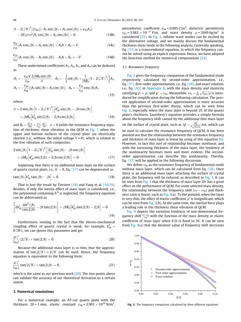
Fig. 2 gives the frequency comparison of the fundamental moderespectively calculated by second-order approximation, i.e.,Eq. (17), first-order approximation, i.e., Eq. (19), and exact solution,i.e., Eq. (A3) in Appendix A, with the mass density and elasticitysatisfying q0 ¼ q, and l0 ¼ c66. Meanwhile, xs ¼ p
2h
ffiffiffiffiffiffiffiffiffiffiffiffi�c66=q
pis intro-
duced for simplification during the following calculation. The pres-ent application of second-order approximation is more accuratethan the pervious first-order theory, which can be seen formFig. 2, especially when the mass layer is beyond 2% of the quartzplate’s thickness. Sauerbrey’s equation provides a simple formulaabout the frequency shift caused by the additional thin mass layer
on the surface of crystal plate, such as Df ¼ 2f 20
AffiffiffiffiffiffiffiffiffiqQ lQp Dm, which can
be used to calculate the resonance frequency of QCM. It has beenpointed out that the relationship between the resonance frequencyand thickness of mass layer is linear by using of this equation [6].However, in fact this sort of relationship becomes nonlinear, andwith the increasing thickness of the mass layer, the tendency ofthe nonlinearity becomes more and more evident. The second-order approximation can describe this nonlinearity. Thereby,Eq. (17) will be applied in the following discussion.
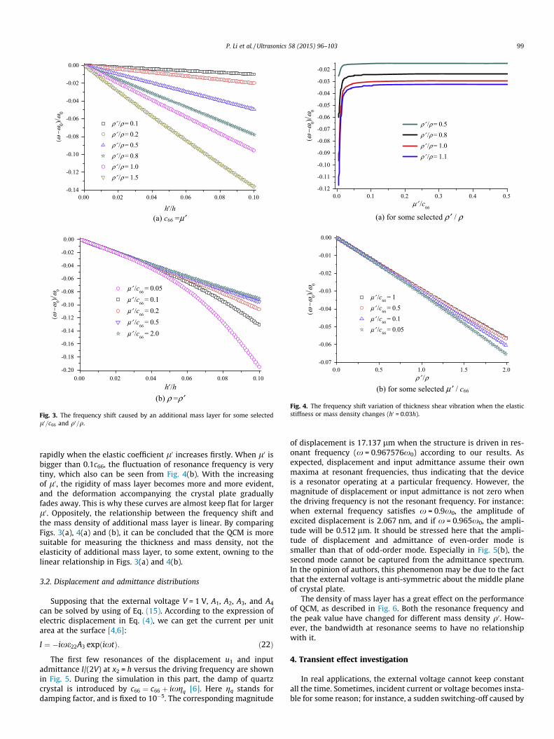
We define x0 as the resonance frequency of fundamental modewithout mass layer, which can be calculated from Eq. (18). Oncethere is an additional mass layer attaching the surface of crystalplate, the frequency will be reduced, as described in Fig. 3. It canbe seen from Fig. 3 that the thickness of mass layer 2h0 has a greateffect on the performance of QCM. For some selected mass density,the relationship between the frequency shift (x �x0) and thick-ness ratio is linear, such as Fig. 3(a). To the pointed, when the layeris very thin, the effect of elastic coefficient l0 is insignificant, whichcan be seen from Fig. 3(b). At the same time, the inertial force playsa leading role in the thickness shear vibration of QCM.
Fig. 4 depicts the variation tendency of non-dimensional fre-quency shift x�x0
x0with the function of the mass density or elastic
coefficient of mass layer when h0/h is fixed to 3%. It can be seenfrom Fig. 4(a) that the absolute value of frequency shift decreases
-0.14
-0.12
-0.10
-0.08
-0.06
-0.04
-0.02
0.00( ω
− ω0)/ ω
0
h′/h
ρ′ /ρ = 0.1ρ′ /ρ = 0.2ρ′ /ρ = 0.5ρ′ /ρ = 0.8ρ′ /ρ = 1.0ρ′ /ρ = 1.5
(a) c66 =μ′
-0.20
-0.18
-0.16
-0.14
-0.12
-0.10
-0.08
-0.06
-0.04
-0.02
0.00
(ω−ω
0)/ω0
h′/h
μ′ /c66 = 0.05μ′ /c
66 = 0.1
μ′ /c66 = 0.2μ′ /c
66 = 0.5
μ′ /c66 = 2.0
(b) ρ =ρ ′
0.00 0.02 0.04 0.06 0.08 0.10
0.00 0.02 0.04 0.06 0.08 0.10
Fig. 3. The frequency shift caused by an additional mass layer for some selectedl0=c66 and q0=q.
-0.12
-0.11
-0.10
-0.09
-0.08
-0.07
-0.06
-0.05
-0.04
-0.03
-0.02
( ω− ω
0)/ ω0
μ′ /c66
ρ′ /ρ = 0.5 ρ′ /ρ = 0.8 ρ′ /ρ = 1.0 ρ′ /ρ = 1.1
(a) for some selected ρ ′ / ρ
-0.07
-0.06
-0.05
-0.04
-0.03
-0.02
-0.01
0.00
( ω− ω
0)/ ω0
ρ′ /ρ
μ′ /c66 = 1μ′ /c66 = 0.5μ′ /c66 = 0.1μ′ /c66 = 0.05
(b) for some selected μ ′ / c66
0.0 0.1 0.2 0.3 0.4 0.5
0.0 0.5 1.0 1.5 2.0
Fig. 4. The frequency shift variation of thickness shear vibration when the elasticstiffness or mass density changes (h0 = 0.03h).
P. Li et al. / Ultrasonics 58 (2015) 96–103 99
rapidly when the elastic coefficient l0 increases firstly. When l0 isbigger than 0.1c66, the fluctuation of resonance frequency is verytiny, which also can be seen from Fig. 4(b). With the increasingof l0, the rigidity of mass layer becomes more and more evident,and the deformation accompanying the crystal plate graduallyfades away. This is why these curves are almost keep flat for largerl0. Oppositely, the relationship between the frequency shift andthe mass density of additional mass layer is linear. By comparingFigs. 3(a), 4(a) and (b), it can be concluded that the QCM is moresuitable for measuring the thickness and mass density, not theelasticity of additional mass layer, to some extent, owning to thelinear relationship in Figs. 3(a) and 4(b).
3.2. Displacement and admittance distributions
Supposing that the external voltage V = 1 V, A1, A2, A3, and A4
can be solved by using of Eq. (15). According to the expression ofelectric displacement in Eq. (4), we can get the current per unitarea at the surface [4,6]:
I ¼ �ixe22A3 expðixtÞ: ð22Þ
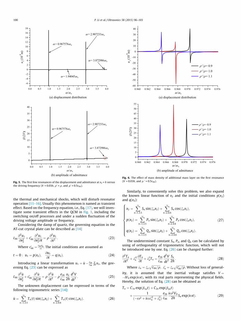
The first few resonances of the displacement u1 and inputadmittance I/(2V) at x2 = h versus the driving frequency are shownin Fig. 5. During the simulation in this part, the damp of quartzcrystal is introduced by c66 ¼ c66 þ ixgq [6]. Here gq stands fordamping factor, and is fixed to 10�5. The corresponding magnitude
of displacement is 17.137 lm when the structure is driven in res-onant frequency (x = 0.967576x0) according to our results. Asexpected, displacement and input admittance assume their ownmaxima at resonant frequencies, thus indicating that the deviceis a resonator operating at a particular frequency. However, themagnitude of displacement or input admittance is not zero whenthe driving frequency is not the resonant frequency. For instance:when external frequency satisfies x = 0.9x0, the amplitude ofexcited displacement is 2.067 nm, and if x = 0.965x0, the ampli-tude will be 0.512 lm. It should be stressed here that the ampli-tude of displacement and admittance of even-order mode issmaller than that of odd-order mode. Especially in Fig. 5(b), thesecond mode cannot be captured from the admittance spectrum.In the opinion of authors, this phenomenon may be due to the factthat the external voltage is anti-symmetric about the middle planeof crystal plate.
The density of mass layer has a great effect on the performanceof QCM, as described in Fig. 6. Both the resonance frequency andthe peak value have changed for different mass density q0. How-ever, the bandwidth at resonance seems to have no relationshipwith it.
4. Transient effect investigation
In real applications, the external voltage cannot keep constantall the time. Sometimes, incident current or voltage becomes insta-ble for some reason; for instance, a sudden switching-off caused by
-6
-4
-2
0
2
4
6
8
10
12
14
16
18
ω = 3.872986ω s
ω = 2.907233ω s
ω = 1.94045ω s
ω = 0.967576ω s
u 1(1
0-9m
)
ω /ω s
(a) displacement distribution
0
5
10
15
20
25
30
35
40
ω = 3.872986ω s
ω = 2.907233ω s
ω = 0.967576ω s
|I/(2
V)|
ω /ω s
(b) amplitude of admittance
0.0 0.5 1.0 1.5 2.0 2.5 3.0 3.5 4.0
0.0 0.5 1.0 1.5 2.0 2.5 3.0 3.5 4.0
Fig. 5. The first few resonances of the displacement and admittance at x2 = h versusthe driving frequency (h0 = 0.03h, q0 = q, and l0 = 0.5c66).
-60
-50
-40
-30
-20
-10
0
10
20
30
40
u 1(1
0-9m
)
ω /ω s
ρ′ /ρ = 0.9 ρ′ /ρ = 1.0 ρ′ /ρ = 1.1
(a) displacement distribution
0.960 0.962 0.964 0.966 0.968 0.970 0.972 0.974 0.976
0.960 0.962 0.964 0.966 0.968 0.970 0.972 0.974 0.976
0
5
10
15
20
25
30
35
40
45
50
55
|I /(2
V)|
ω /ω s
ρ′ /ρ = 0.9ρ′ /ρ = 1.0ρ′ /ρ = 1.1
(b) amplitude of admittance
Fig. 6. The effect of mass density of additional mass layer on the first resonance(h0 = 0.03h, and l 0 = 0.5c66).
100 P. Li et al. / Ultrasonics 58 (2015) 96–103
the thermal and mechanical shocks, which will disturb resonatoroperation [11–16]. Usually this phenomenon is named as transienteffect. Based on the frequency equation, i.e., Eq. (17), we will inves-tigate some transient effects in the QCM in Fig. 1, including theswitching on/off processes and under a sudden fluctuation of thedriving voltage amplitude or frequency.
Considering the damp of quartz, the governing equation in theAT-cut crystal plate can be described as [14]
�c66@2u1
@x22
þ c066@3u1
@x22@t¼ q
@2u1
@t2 : ð23Þ
Where c066 ¼c66gq
x . The initial conditions are assumed as
t ¼ 0 : u1 ¼ pðx2Þ;@u1
@t¼ qðx2Þ: ð24Þ
Introducing a linear transformation u1 ¼ u� e26c66
V2h x2, the gov-
erning Eq. (23) can be expressed as
�c66@2u@x2
2
þ c066@3u@x2
2@t¼ q
@2u@t2 � q
e26
c66
x2
2hd2V
dt2 : ð25Þ
The unknown displacement can be expressed in terms of thefollowing trigonometric series [14]:
u ¼X1
n¼1;3;5
TnðtÞ sinðnnx2Þ þX1
n¼2;4;6
TnðtÞ cosðnnx2Þ: ð26Þ
Similarly, to conveniently solve this problem, we also expandthe known linear function of x2 and the initial conditions p(x2)and q(x2):
x2 ¼X1
n¼1;3;5
Sn sinðnnx2Þ þX1
n¼2;4;6
Sn cosðnnx2Þ;
pðx2Þ ¼X1
n¼1;3;5
Pn sinðnnx2Þ þX1
n¼2;4;6
Pn cosðnnx2Þ;
qðx2Þ ¼X1
n¼1;3;5
Qn sinðnnx2Þ þX1
n¼2;4;6
Q n cosðnnx2Þ:
8>>>>>>>>>><>>>>>>>>>>:
ð27Þ
The undetermined constant Sn, Pn, and Qn can be calculated byusing of orthogonality of trigonometric function, which will notbe introduced one by one. Eq. (26) can be changed further:
@2Tn
@t2 þ k02n@Tn
@tþ k2
nTn ¼e26
c66
d2V
dt2
Sn
2h: ð28Þ
Where kn ¼ nn
ffiffiffiffiffiffiffiffiffiffiffiffi�c66=q
p; k0n ¼ nn
ffiffiffiffiffiffiffiffiffiffiffiffic066=q
p. Without loss of general-
ity, it is assumed that the inertial voltage satisfies V ¼�iV0 expðixtÞ, with its real parts representing the physical fields.Hereby, the solution of Eq. (28) can be obtained as
Tn ¼ C1n expðb1ntÞ þ C2n expðb2ntÞ
þ 1ð�x2 þ ixk02n þ k2
nÞe26
c66
ix2V0
2hSn expðixtÞ: ð29Þ
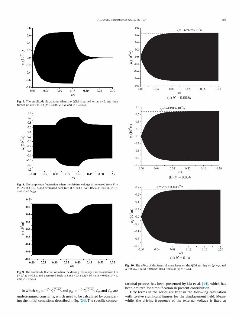
Fig. 7. The amplitude fluctuation when the QCM is turned on at t = 0, and thenturned off at t = 0.15 s (h0 = 0.03h, q0 = q, and l0 = 0.5c66).
Fig. 8. The amplitude fluctuation when the driving voltage is increased from V toV + DV at t = 0.3 s, and decreased back to V at t = 0.4 s (DV = 0.5 V, h0 = 0.03h, q0 = q,and l0 = 0.5c66).
Fig. 9. The amplitude fluctuation when the driving frequency is increased from f tof + Df at t = 0.3 s, and decreased back to f at t = 0.4 s (Df = 10 Hz, h0 = 0.03h, q0 = q,and l0 = 0.5c66).
(a) h′ = 0.005h
(b) h′ = 0.03h
(c) h′ = 0.1h
Fig. 10. The effect of thickness of mass layer on the QCM turning on (q0 = q, andl0 = 0.5c66): (a) h0 = 0.005h; (b) h0 = 0.03h; (c) h0 = 0.1h.
P. Li et al. / Ultrasonics 58 (2015) 96–103 101
In which b1n ¼�k02n þ
ffiffiffiffiffiffiffiffiffiffiffiffik04n �4k2
n
p2 , and b2n ¼
�k02n �ffiffiffiffiffiffiffiffiffiffiffiffik04n �4k2
n
p2 . C1n and C2n are
undetermined constants, which need to be calculated by consider-ing the initial conditions described in Eq. (24). The specific compu-
tational process has been presented by Liu et al. [14], which hasbeen omitted for simplification in present contribution.
Fifty terms in the series are kept in the following calculationwith twelve significant figures for the displacement field. Mean-while, the driving frequency of the external voltage is fixed at
102 P. Li et al. / Ultrasonics 58 (2015) 96–103
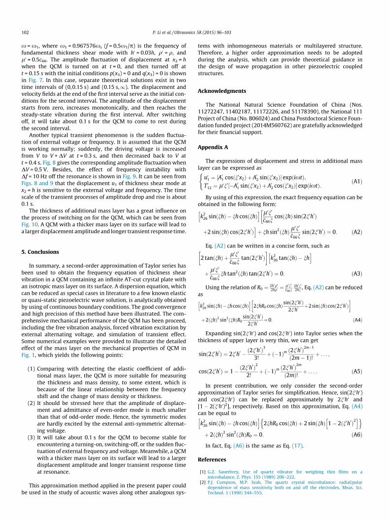
x = x1, where x1 = 0.967576xs (f = 0.5x1/p) is the frequency offundamental thickness shear mode with h0 = 0.03h, q0 = q, andl0 = 0.5c66. The amplitude fluctuation of displacement at x2 = hwhen the QCM is turned on at t = 0, and then turned off att = 0.15 s with the initial conditions p(x3) = 0 and q(x3) = 0 is shownin Fig. 7. In this case, separate theoretical solutions exist in twotime intervals of (0,0.15 s) and (0.15 s,1). The displacement andvelocity fields at the end of the first interval serve as the initial con-ditions for the second interval. The amplitude of the displacementstarts from zero, increases monotonically, and then reaches thesteady-state vibration during the first interval. After switchingoff, it will take about 0.1 s for the QCM to come to rest duringthe second interval.
Another typical transient phenomenon is the sudden fluctua-tion of external voltage or frequency. It is assumed that the QCMis working normally; suddenly, the driving voltage is increasedfrom V to V + DV at t = 0.3 s, and then decreased back to V att = 0.4 s. Fig. 8 gives the corresponding amplitude fluctuation whenDV = 0.5 V. Besides, the effect of frequency instability withDf = 10 Hz off the resonance is shown in Fig. 9. It can be seen fromFigs. 8 and 9 that the displacement u1 of thickness shear mode atx2 = h is sensitive to the external voltage and frequency. The timescale of the transient processes of amplitude drop and rise is about0.1 s.
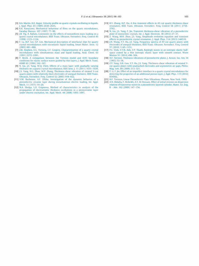
The thickness of additional mass layer has a great influence onthe process of switching on for the QCM, which can be seen fromFig. 10. A QCM with a thicker mass layer on its surface will lead toa larger displacement amplitude and longer transient response time.
5. Conclusions
In summary, a second-order approximation of Taylor series hasbeen used to obtain the frequency equation of thickness shearvibration in a QCM containing an infinite AT-cut crystal plate withan isotropic mass layer on its surface. A dispersion equation, whichcan be reduced as special cases in literature to a few known elasticor quasi-static piezoelectric wave solution, is analytically obtainedby using of continuous boundary conditions. The good convergenceand high precision of this method have been illustrated. The com-prehensive mechanical performance of the QCM has been proceed,including the free vibration analysis, forced vibration excitation byexternal alternating voltage, and simulation of transient effect.Some numerical examples were provided to illustrate the detailedeffect of the mass layer on the mechanical properties of QCM inFig. 1, which yields the following points:
(1) Comparing with detecting the elastic coefficient of addi-tional mass layer, the QCM is more suitable for measuringthe thickness and mass density, to some extent, which isbecause of the linear relationship between the frequencyshift and the change of mass density or thickness.
(2) It should be stressed here that the amplitude of displace-ment and admittance of even-order mode is much smallerthan that of odd-order mode. Hence, the symmetric modesare hardly excited by the external anti-symmetric alternat-ing voltage.
(3) It will take about 0.1 s for the QCM to become stable forencountering a turning-on, switching-off, or the sudden fluc-tuation of external frequency and voltage. Meanwhile, a QCMwith a thicker mass layer on its surface will lead to a largerdisplacement amplitude and longer transient response timeat resonance.
This approximation method applied in the present paper couldbe used in the study of acoustic waves along other analogous sys-
tems with inhomogeneous materials or multilayered structure.Therefore, a higher order approximation needs to be adoptedduring the analysis, which can provide theoretical guidance inthe design of wave propagation in other piezoelectric coupledstructures.
Acknowledgments
The National Natural Science Foundation of China (Nos.11272247, 11402187, 11172226, and 51178390), the National 111Project of China (No. B06024) and China Postdoctoral Science Foun-dation funded project (2014M560762) are gratefully acknowledgedfor their financial support.
Appendix A
The expressions of displacement and stress in additional masslayer can be expressed as
u01 ¼ ½A01 cosðn0x2Þ þ A02 sinðn0x2Þ� expðixtÞ;
T 012 ¼ l0n0½�A01 sinðn0x2Þ þ A02 cosðn0x2Þ� expðixtÞ:
(ðA1Þ
By using of this expression, the exact frequency equation can beobtained in the following form:
k226 sinðnhÞ � nh cosðnhÞ
h i l0n0
�c66ncosðnhÞ sinð2n0h0Þ
�
þ2 sinðnhÞ cosð2n0h0Þiþ nh sin2ðnhÞ l
0n0
�c66nsinð2n0h0Þ ¼ 0: ðA2Þ
Eq. (A2) can be written in a concise form, such as
2 tanðnhÞ þ l0n0�c66n
tanð2n0h0Þ� �
k226 tanðnhÞ � nh
h i
þ l0n0
�c66nnh tan2ðnhÞ tanð2n0h0Þ ¼ 0: ðA3Þ
Using the relation of R0 ¼ 2h0q02hq ¼
l0n0�c66n
2h0n0
2hn , Eq. (A2) can be reducedas
k226 sinðnhÞ�nhcosðnhÞ
h i2nhR0 cosðnhÞsinð2n0h0Þ
2n0h0þ2sinðnhÞcosð2n0h0Þ
� �
þ2ðnhÞ2 sin2ðnhÞR0sinð2n0h0Þ
2n0h0¼0: ðA4Þ
Expanding sin(2n0h0) and cos(2n0h0) into Taylor series when thethickness of upper layer is very thin, we can get
sinð2n0h0Þ ¼ 2n0h0 � ð2n0h0Þ3
3!þ ð�1Þm ð2n0h0Þ2m�1
ð2m� 1Þ! þ . . . ;
cosð2n0h0Þ ¼ 1� ð2n0h0Þ2
2!þ ð�1Þm ð2n0h0Þ2m
ð2mÞ! þ . . . : ðA5Þ
In present contribution, we only consider the second-orderapproximation of Taylor series for simplification. Hence, sin(2n0h0)and cos(2n0h0) can be replaced approximately by 2n0h0 and[1 � 2(n0h0)2], respectively. Based on this approximation, Eq. (A4)can be equal to
k226 sinðnhÞ � nh cosðnhÞ
h i2nhR0 cosðnhÞ þ 2 sinðnhÞ 1� 2ðn0h0Þ2
h in oþ 2ðnhÞ2 sin2ðnhÞR0 ¼ 0: ðA6Þ
In fact, Eq. (A6) is the same as Eq. (17).
References
[1] G.Z. Sauerbrey, Use of quartz vibrator for weighing thin films on amicrobalance, Z. Phys. 155 (1989) 206–222.
[2] P.J. Cumpson, M.P. Seah, The quartz crystal microbalance: radial/polardependence of mass sensitivity both on and off the electrodes, Meas. Sci.Technol. 1 (1990) 544–555.
P. Li et al. / Ultrasonics 58 (2015) 96–103 103
[3] B.A. Martin, H.E. Hager, Velocity profile on quartz crystals oscillating in liquids,J. Appl. Phys. 65 (1989) 2630–2635.
[4] K.K. Kanazawa, Mechanical behaviour of films on the quartz microbalance,Faraday Discuss. 107 (1997) 77–90.
[5] J.R. Vig, A. Ballato, Comments on the effects of nonuniform mass loading on aquartz crystal microbalance, IEEE Trans. Ultrason. Ferroelect. Freq. Control 45(1998) 1123–1124.
[6] F. Lu, H.P. Lee, S.P. Lim, Mechanical description of interfacial slips for quartzcrystal microbalances with viscoelastic liquid loading, Smart Mater. Strut. 12(2003) 881–888.
[7] J.M. Stephen, E.G. Victoria, C.F. Gregory, Characterization of a quartz crystalmicrobalance with simultaneous mass and liquid loading, Anal. Chem. 63(1991) 2272–2281.
[8] P. Bovik, A comparison between the Tiersten model and O(H) boundaryconditions for elastic surface waves guided by thin layers, J. Appl. Mech. Trans.ASME 63 (1996) 162–167.
[9] N. Liu, J.S. Yang, W.Q. Chen, Effects of a mass layer with gradually varyingthickness on a quartz crystal microbalance, IEEE Sens. J. 11 (2011) 1635–1639.
[10] J.S. Yang, H.G. Zhou, W.P. Zhang, Thickness-shear vibration of rotated Y-cutquartz plates with relatively thick electrodes of unequal thickness, IEEE Trans.Ultrason. Ferroelect. Freq. Control 52 (2005) 918–922.
[11] V.M. Bazhenov, A.F. Ulitko, Investigation of the dynamic behavior of apiezoelectric ceramic layer during instantaneous electric loading, Int. Appl.Mech. 11 (1975) 16–20.
[12] N.A. Shulga, L.O. Grigoreva, Method of characteristics in analysis of thepropagation of electroelastic thickness oscillations in a piezoceramic layerunder electric excitation, Int. Appl. Mech. 44 (2008) 1093–1097.
[13] R.Y. Zhang, H.P. Hu, A few transient effects in AT-cut quartz thickness-shearresonators, IEEE Trans. Ultrason. Ferroelect. Freq. Control 58 (2011) 2758–2762.
[14] N. Liu, J.S. Yang, F. Jin, Transient thickness-shear vibration of a piezoelectricplate of monoclinic crystals, Int. J. Appl. Electrom. 38 (2012) 27–37.
[15] Z. Wang, M.H. Zhao, J.S. Yang, Amplitude evolution equation and transienteffects in piezoelectric crystal resonators, J. Appl. Phys. 114 (2013) 144510.
[16] J.N. Wang, Y.T. Hu, J.S. Yang, Frequency spectra of AT-cut quartz plates withelectrodes of unequal thickness, IEEE Trans. Ultrason. Ferroelect. Freq. Control57 (2010) 1145–1151.
[17] P.C. Vinh, V.T.N. Anh, V.P. Thanh, Rayleigh waves in an isotropic elastic half-space coated by a thin isotropic elastic layer with smooth contact, WaveMotion 51 (2014) 496–504.
[18] H.F. Tiersten, Thickness vibrations of piezoelectric plates, J. Acoust. Soc. Am. 34(1963) 53–58.
[19] Z.T. Yang, S.H. Guo, Y.T. Hu, J.S. Yang, Thickness-shear vibration of rotated Y-cut quartz plates with unattached electrodes and asymmetric air gaps, Philos.Mag. Lett. 89 (2009) 313–321.
[20] P. Li, F. Jin, Effect of an imperfect interface in a quartz crystal microbalance fordetecting the properties of an additional porous layer, J. Appl. Phys. 115 (2014)054502.
[21] H.F. Tiersten, Linear Piezoelectric Plate Vibrations, Plenum, New York, 1969.[22] A.N. Abdalla, F. Alsheikh, A.Y. Al-Hossain, Effect of initial stresses on dispersion
relation of transverse waves in a piezoelectric layered cylinder, Mater. Sci. Eng.B – Adv. 162 (2009) 147–154.